CN1151771A - Device for reducing the effects of the tendency of a paper web to adhere to a drying cylinder in a papermaking machine - Google Patents
Device for reducing the effects of the tendency of a paper web to adhere to a drying cylinder in a papermaking machineDownload PDFInfo
- Publication number
- CN1151771A CN1151771ACN95193970ACN95193970ACN1151771ACN 1151771 ACN1151771 ACN 1151771ACN 95193970 ACN95193970 ACN 95193970ACN 95193970 ACN95193970 ACN 95193970ACN 1151771 ACN1151771 ACN 1151771A
- Authority
- CN
- China
- Prior art keywords
- drying
- web
- cord
- nozzle
- drum
- Prior art date
- Legal status (The legal status is an assumption and is not a legal conclusion. Google has not performed a legal analysis and makes no representation as to the accuracy of the status listed.)
- Granted
Links
- 238000001035dryingMethods0.000titleclaimsabstractdescription92
- 230000000694effectsEffects0.000titleabstractdescription4
- 238000011144upstream manufacturingMethods0.000claimsabstractdescription6
- 238000007664blowingMethods0.000claimsdescription13
- 230000002093peripheral effectEffects0.000claimsdescription9
- 239000004744fabricSubstances0.000abstractdescription9
- 230000007704transitionEffects0.000abstractdescription4
- 230000001627detrimental effectEffects0.000description4
- 239000007921spraySubstances0.000description2
- 230000004323axial lengthEffects0.000description1
- 230000015572biosynthetic processEffects0.000description1
- 230000007423decreaseEffects0.000description1
- 239000002184metalSubstances0.000description1
- 238000007789sealingMethods0.000description1
- 239000004753textileSubstances0.000description1
Images


Classifications
- D—TEXTILES; PAPER
- D21—PAPER-MAKING; PRODUCTION OF CELLULOSE
- D21F—PAPER-MAKING MACHINES; METHODS OF PRODUCING PAPER THEREON
- D21F5/00—Dryer section of machines for making continuous webs of paper
- D21F5/02—Drying on cylinders
- D21F5/04—Drying on cylinders on two or more drying cylinders
- D21F5/042—Drying on cylinders on two or more drying cylinders in combination with suction or blowing devices
Landscapes
- Drying Of Solid Materials (AREA)
- Paper (AREA)
Abstract
Description
Translated fromChinese本发明涉及在造纸机器的干燥段中的一种装置,该干燥段包括多个干燥滚筒和引导辊,被干燥帘布支承的卷筒纸交替地在干燥滚筒和引导辊上运行,以此方式干燥帘布把卷筒纸压靠在干燥滚筒上,并且干燥帘布位于卷筒纸与引导辊之间,所述装置适用于当卷筒纸从干燥滚筒运行到后继的引导辊时减少卷筒纸粘附到干燥滚筒上的现象,该装置包括一个吹风装置,此吹风装置的一个壁被设置在卷筒纸和干燥帘布从干燥滚筒向引导辊传送处,此壁朝向干燥帘布,并基本上与干燥帘布平行地伸展,在该壁与干燥帘布之间形成一个狭窄的空气隙,此吹风装置有一个喷嘴设置在壁的端部,位于相对卷筒纸和干燥帘布的运行方向上游的位置,所述喷嘴适合于以高速朝向离开空气隙的干燥帘布喷出空气。The invention relates to an arrangement in the drying section of a papermaking machine comprising a plurality of drying cylinders and guide rolls, over which a web supported by drying fabrics runs alternately, in such a way that the The cord presses the web against the dryer drum and the dryer cord is located between the web and the guide rolls, said device being adapted to reduce web sticking as the web runs from the dryer drum to the following guide rolls onto the drying drum, the device comprising a blowing device, a wall of which is arranged at the place where the web and the drying cord are conveyed from the drying drum to the guide rollers, the wall faces the drying cord and is substantially in contact with the drying cord Extending in parallel, forming a narrow air gap between the wall and the drying cord, the blowing device has a nozzle arranged at the end of the wall at a position upstream relative to the direction of travel of the web and the drying cord, said nozzle Suitable for blowing air at high velocity towards the drying cord away from the air gap.
在带有上述类型的干燥段的造纸机器中,当卷筒纸向下一个引导辊运行时有粘附到干燥滚筒上的倾向。如果出现这种粘附,会使空气动力作用力经过干燥帘布以一种有害的方式作用到卷筒纸上。当造纸机器以高速运行时,即,当卷筒纸和干燥帘布以高速(1200米/分以上)通过干燥段时,这些作用力的有害效果特别明显。这种粘附的倾向在干燥段开始的部分最严重,随着卷筒纸变干燥而减小,并且当卷筒纸薄和要生产低克数纸时最严重。In papermaking machines with drying sections of the type described above, there is a tendency for the web to stick to the drying cylinder as it runs towards the next guide roll. If such sticking occurs, aerodynamic forces can be applied to the web in a detrimental manner through the dryer fabric. The detrimental effect of these forces is particularly pronounced when the papermaking machine is operating at high speeds, ie when the web and drying cords pass through the drying section at high speeds (above 1200 m/min). This sticking tendency is most severe at the beginning of the drying section, decreases as the web dries, and is most severe when the web is thin and low grammage paper is to be produced.
如果卷筒纸粘附到干燥滚筒上,并随后跟随着干燥滚筒运动一段距离,在离开干燥滚筒并返回到干燥帘布前,会在卷筒纸与干燥帘布之间出现一个气泡。在这个气泡与干燥帘布的另一面上的空间之间,会出现通过干燥帘布的空气联通。这种空气联通形成了复杂的和不稳定的流场,这可能增大气泡并引起卷筒纸拍动,从而可能引起卷筒纸的折叠或断裂。If the web sticks to the dryer drum and then follows the dryer drum for some distance, an air bubble will develop between the web and the dryer cord before leaving the dryer drum and returning to the dryer cord. Between this air bubble and the space on the other side of the drying cord, air communication through the drying cord occurs. This air communication creates a complex and unstable flow field, which can increase air bubbles and cause the web to flap, possibly causing the web to fold or break.
本发明的目的是提供一种装置,它引导空气动力作用力,使得它们对卷筒纸的有害作用被消除,或至少被减少,结果,使得造纸机器可以以高速运行,此外,该装置设计成可以把空气的作用(这一作用对于实现所想达到的效果是必须的)减小。It is an object of the present invention to provide a device which directs the aerodynamic forces so that their detrimental effect on the web is eliminated, or at least reduced, as a result of which the papermaking machine can be run at high speeds, in addition, the device is designed to The effect of air (which is necessary to achieve the desired effect) can be reduced.
按照本发明,这一目的的实现是靠上述提到的那种类型的装置,其特征在于喷嘴有狭缝形的开口,并且喷嘴被设计成沿着开口的中心平面方向喷射出一股很好地确定了的空气射流,其特征还在于喷嘴的取向使得它的中心平面沿着第一直线与干燥滚筒的圆周表面相交,该第一直线位于第二直线的上游,卷筒纸沿着第二直线离开干燥滚筒,其特征还在于喷嘴开口的中心平面和干燥滚筒的切平面之间形成一个10-20度,最好15度的角度,所述切平面通过所述第一直线伸展。According to the invention, this object is achieved by means of the above-mentioned type, characterized in that the nozzle has a slit-shaped opening, and the nozzle is designed to spray a jet of fine air along the central plane of the opening. A well-defined air jet, further characterized in that the nozzle is oriented such that its central plane intersects the peripheral surface of the drying drum along a first straight line upstream of a second straight line along which the web follows A second straight line leaving the drying drum is also characterized in that an angle of 10-20 degrees, preferably 15 degrees, is formed between the center plane of the nozzle opening and a tangential plane of the drying drum, said tangential plane extending through said first straight line .
这两根直线之间沿着干燥滚筒的圆周表面的距离最好为30-50毫米。The distance between these two straight lines along the peripheral surface of the drying drum is preferably 30-50 mm.
现在将参考附图更详细地描述本发明。The invention will now be described in more detail with reference to the accompanying drawings.
图1为造纸机器的干燥段部分的示意图。Figure 1 is a schematic illustration of the drying section of a paper machine.
图2示出了按照本发明的一种装置,它装在造纸机器的干燥段中。Figure 2 shows a device according to the invention installed in the drying section of a paper machine.
图3示出了在该装置中所包括的一个吹风装置。Figure 3 shows a blower included in the device.
图4-6为设置在吹风装置中的喷嘴在沿着该吹风装置长度方向的三个不同位置的剖面图。4-6 are cross-sectional views of the nozzles arranged in the blowing device at three different positions along the length direction of the blowing device.
图7示出了喷嘴射出的空气射流打到干燥滚筒上的几何条件。Figure 7 shows the geometry of the air jets from the nozzles hitting the drying drum.
图1示出了造纸机器的干燥段部分,在这一段中设有多个蒸汽加热的干燥滚筒1和多个带孔的引导辊2。把干燥滚筒1设置为水平的上排,而引导辊2(它们的直径比干燥滚筒1的直径明显地小)被设置为水平的下排。在每一对相邻的干燥滚筒1之间设置一个引导辊2。一个限定元件3(图2)被固定地设置在各自的旋转引导辊2中。该限定元件3包括一个带有两个径向翼片3b的圆柱3a,这些翼片的外端部与引导辊2的内圆周表面密封地接合。限定元件3的圆筒3a在两个翼片3b下面的那一部分是带孔的。在圆筒3a中保持着一个负压,因此,在引导辊2的下部,即由元件3所限定的那一部分保持着一个负压。Figure 1 shows part of the drying section of a paper machine in which a plurality of steam-heated drying cylinders 1 and a plurality of perforated
对于本发明来说,按照上面所描述的示例设计干燥段没有本质的重要性。例如,引导辊不需要是采用内部负压的那种类型。Designing the drying section according to the example described above is not of essential importance for the invention. For example, the guide rollers need not be of the type using internal negative pressure.
卷筒纸4通过干燥段被干燥。卷筒纸4以之字形在干燥滚筒1和引导辊2上运行。一透过性的干燥帘布5支承着卷筒纸4,该干燥帘布例如包含一种纺织品,在干燥滚筒上它位于卷筒纸4的外侧,把卷筒纸压靠在干燥滚筒上,而在引导辊2上它位于卷筒纸4的里侧,即在卷筒纸与各引导辊之间(见图2)。引导辊中所保持的负压把卷筒纸4吸靠在引导辊2上,这一负压通过引导辊2的孔和透过性的干燥帘布5作用到卷筒纸4上。The
如前言中所提到的那样,当卷筒纸运行到后继的引导辊2时(即在卷筒纸4和干燥帘布5的过渡部分,在图2中以A表示),卷筒纸4有粘附到各干燥滚筒1上的倾向。As mentioned in the preface, when the web runs to the subsequent guide roll 2 (ie at the transition between the
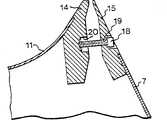
为了减少卷筒纸4粘附到干燥滚筒1上(因此卷筒纸离开干燥帘布5,并在它离开干燥滚筒返回到干燥帘布5上之前伴随干燥滚筒1一段距离)的倾向,采用了一个吹风装置6,它被设置在引导辊2的上方(图2)。该吹风装置6在干燥滚筒和引导辊1和2的整个轴向长度上伸展,也在横向上占据两个相邻的干燥滚筒1之间的几乎整个空间。吹风装置6有一个侧壁7,在过渡部分A形成了一个机械屏蔽。该侧壁7朝向干燥帘布5,并与之平行地伸展,从而在侧壁7与干燥帘布5之间形成一个狭窄的空气间隙8。吹风装置6有一个底部9,沿着引导辊2的上部伸展,并离开引导辊的圆周表面一个小距离。侧壁7在其下端有一个唇形密封件10,它与引导辊2的圆周表面密封地接合。吹风装置6还有一个上壁11。在上壁11与侧壁7之间的角部设有一个喷嘴12,它有纵向的狭缝形开口13,并被设置成以高速朝向离开空气隙8的干燥帘布5喷出空气,狭缝形的开口13的嘴位于角部。In order to reduce the tendency of the
所射出的空气流(箭头P1)使由干燥帘布5夹带的空气边界层产生“剥落”,防止了由干燥帘布5夹带的空气被引入到空气隙8中。所喷射出的空气流的喷射作用和干燥帘布5由空气隙8把空气输运走的作用在空气隙处代之以产生一个负压。这个负压通过多孔的干燥帘布5作用到卷筒纸4上,防止了如上所述的不稳定空气流场在过渡部分A中形成,这使得空气动力作用力对卷筒纸的有害作用减小。The emitted air flow (arrow P1 ) “flaps” the boundary layer of air entrained by the
吹风装置6的上壁11有朝上的中凹形状(如图2和3中所示)使得容易把“被剥落的”空气流(箭头P2)从两个相邻的干燥滚筒1之间的空间移开。The
喷嘴12包括两根直的金属窄条14和15,借助于螺丝16把一根14装到上壁11的下侧面上(图4),借助于螺丝17把另一根15装到侧壁7的内侧面上(图4)。螺丝16和17在窄条14和15的长度上均匀分布。The
在窄条14和15之间形成有纵向的狭缝形开口13。此开口有一个收缩的入口部分13a和相继的对空气流进行导向的部分13b,在此部分,开口的侧壁彼此平行,并与开口的中心平面C平行(图4),该中心平面在侧壁之间正中,并且开口13相对于该平面是对称的。狭缝形开口13的13b部分经过一个收缩部分13c进入到一个短的出口部或嘴部13d,在此出口部它的侧壁也与中心平面C平行。在所示出的实施例中,狭缝在入口部分13a的宽端的宽度为20毫米,在入口部分13a的窄端,在13b部分以及在收缩部分13c的宽端的宽度为10毫米,而在收缩部分13c的窄端以及在出口部分13d的宽度为2.5毫米。在所示出的实施例中,入口部分13a的长度为15毫米,直线部分13b的长度为28毫米,收缩部分13c的长度为9.5毫米,而出口部分13d的长度为2.5毫米。A longitudinal slit-shaped opening 13 is formed between the
狭缝形开口13的直的空气流导向部分13b用来产生被很好限制并被很好确定了的空气射流,因此它的长度至少为狭缝在出口部分13d的宽度的五倍。在这里,被很好确定了的空气射流指的是这样一种空气流,它沿着中心平面C的速度在离开喷嘴出口大约十倍于所述狭缝宽度的一个距离上为出口处空气射流的速度的0.68-0.78倍,特别地为0.73倍。如果在其中设置一块屏障形空气流导向插入件,可以减小此空气流导向部分13b的长度,该插入件有多个通孔与狭缝形开口13的中心平面C平行地伸展。The straight airflow guide portion 13b of the slit-shaped opening 13 serves to generate a well-restricted and well-defined air jet, so that its length is at least five times the width of the slit at the outlet portion 13d. Here, a well-defined air jet refers to an air stream whose velocity along the central plane C is equal to that of the air jet at the exit at a distance from the nozzle outlet of about ten times the width of the slit. 0.68-0.78 times the speed of , especially 0.73 times. The length of this airflow guiding portion 13b can be reduced if a barrier-shaped airflow guiding insert having a plurality of through holes extending parallel to the center plane C of the slit-shaped opening 13 is provided therein.
这两根窄条14和15可以借助于多个螺丝18相对于彼此进行调整,这些螺丝在窄条的长度上均匀地分布,它们中之一在图5中示出。每个螺丝18被紧固到装到侧壁7上的窄条15上的一个螺纹孔19中,并伸展进装到上壁11上的窄条14上的一个凹部20中。当螺丝18的端部压靠在凹部20的底部上并把螺丝18进一步拧进孔19中时,窄条14和15以及壁7和11因此就会克服壁的弹性作用被压得彼此离开。The two
借助于多个螺丝21把窄条14和15固定在设定部分上,这些螺丝在窄条的长度上均匀地分布,它们中之一在图6中示出。每个螺丝21穿过窄条15(此窄条被装到侧壁7上)中的间隙孔22伸展,并被紧固在窄条14(此窄条被装到上壁11上)中的一个螺纹孔23中。螺丝21的头部压靠着窄条15的外侧面。The
调节和固定螺丝18和21的上述这种设置使得在一定范围内在喷嘴12的整个长度上实现不同的设定成为可能,例如在吹风装置6的端壁上提供一个较宽的狭缝形开口13。The above-mentioned arrangement of adjusting and fixing
喷嘴12被这样地取向(见图7):它的中心平面C沿着一条直线L1与干燥滚筒1的圆周表面相交,该直线L1位于直线L2的上游,卷筒纸4沿着直线L2离开干燥滚筒1。如看到的那样,两根直线L1和L2垂直于图7中所画的平面。在直线L1和L2之间沿着干燥滚筒1的圆周表面的距离D为30-50毫米。因为干燥滚筒1的直径通常为大约1500毫米-大约1800毫米,所以在直线L1和L2之间伸展的干燥滚筒1的圆周表面的弧形部分(如图7中所示)可以近似地看成一个平面。中心平面C和干燥滚筒1的切平面T之间形成一个角度α,为10度-20度,最好为15度,所述切平面穿过直线L1伸展。The
Claims (3)
Translated fromChineseApplications Claiming Priority (3)
| Application Number | Priority Date | Filing Date | Title |
|---|---|---|---|
| SE9402346-2 | 1994-07-04 | ||
| SE9402346ASE502817C2 (en) | 1994-07-04 | 1994-07-04 | Device adapted to reduce the effects of a paper web's tendency to adhere to a drying cylinder in a paper machine |
| SE94023462 | 1994-07-04 |
Publications (2)
| Publication Number | Publication Date |
|---|---|
| CN1151771Atrue CN1151771A (en) | 1997-06-11 |
| CN1045647C CN1045647C (en) | 1999-10-13 |
Family
ID=20394610
Family Applications (1)
| Application Number | Title | Priority Date | Filing Date |
|---|---|---|---|
| CN95193970AExpired - Fee RelatedCN1045647C (en) | 1994-07-04 | 1995-06-20 | Device for reducing web sticking to drying cylinders in papermaking machines |
Country Status (11)
| Country | Link |
|---|---|
| US (1) | US5711088A (en) |
| EP (1) | EP0772713B1 (en) |
| CN (1) | CN1045647C (en) |
| AT (1) | ATE183788T1 (en) |
| AU (1) | AU2940295A (en) |
| CA (1) | CA2193693A1 (en) |
| DE (1) | DE69511702T2 (en) |
| FI (1) | FI970011A0 (en) |
| SE (1) | SE502817C2 (en) |
| WO (1) | WO1996001341A1 (en) |
| ZA (1) | ZA955325B (en) |
Cited By (3)
| Publication number | Priority date | Publication date | Assignee | Title |
|---|---|---|---|---|
| CN101240513B (en)* | 2007-02-09 | 2012-05-02 | 沃依特专利有限责任公司 | Method and device for transferring a material web, in particular a paper web, from a press section to a dryer section |
| CN101910513B (en)* | 2007-12-31 | 2013-06-19 | 美卓造纸机械公司 | Arrangement and method for saving energy in drying section of paper machine or the like |
| CN119221318A (en)* | 2024-12-03 | 2024-12-31 | 淄博王村纸业有限公司 | An anti-blocking self-cleaning pneumatic paper feeding device |
Families Citing this family (10)
| Publication number | Priority date | Publication date | Assignee | Title |
|---|---|---|---|---|
| DE19741517A1 (en) | 1997-09-20 | 1999-03-25 | Voith Sulzer Papiermasch Gmbh | Process for reducing the adhesion of a moist fibrous web to a rotating roller |
| DE19958875A1 (en)* | 1999-12-07 | 2001-07-19 | Voith Paper Patent Gmbh | Web drying station has a tension control for the drying blanket to give a trouble-free passage through the station and a clean pick-up from the heated drying cylinders |
| DE19958867A1 (en)* | 1999-12-07 | 2001-07-12 | Voith Paper Patent Gmbh | Fiber web drying station has controlled parameters for the drying blanket tension and the temp of the drying cylinders for a trouble-free web passage through the station at high speeds |
| US6513263B2 (en) | 2000-10-06 | 2003-02-04 | Enerquin Air Inc. | Ventilator for offset pocket and method of ventilating the same |
| US6725569B2 (en) | 2001-01-30 | 2004-04-27 | Enerquin Air Inc. | Device and method for ventilating an offset pocket space in a papermaking machine |
| US6412192B1 (en) | 2001-01-30 | 2002-07-02 | Enerquin Air Inc. | Device and method for ventilating an offset pocket space in a papermaking machine |
| DE102004047238A1 (en)* | 2004-09-29 | 2006-04-13 | Voith Paper Patent Gmbh | applicator |
| FI20050596A0 (en)* | 2005-06-06 | 2005-06-06 | Metso Paper Inc | Apparatus and method for sealing a pocket space existing between dryer cylinders in a paper machine or equivalent |
| CN101487198B (en)* | 2009-02-10 | 2011-07-20 | 湖南正大轻科机械有限公司 | Paper web stabilizer of high-speed paper machine |
| DE102010056576B8 (en) | 2010-12-30 | 2015-05-07 | Paprima Industries Inc. | Papermaking machine and method of making paper |
Family Cites Families (10)
| Publication number | Priority date | Publication date | Assignee | Title |
|---|---|---|---|---|
| SE450957B (en)* | 1983-05-30 | 1987-08-17 | Flaekt Ab | SEALER AT CYLINDERTORK |
| FI69332C (en)* | 1984-03-02 | 1986-01-10 | Valmet Oy | ANORDNING I TORKNINGSPARTIET AV EN PAPPERSMASKIN |
| FI68279C (en)* | 1984-03-22 | 1985-08-12 | Valmet Oy | FOERFARANDE OCH ANORDNING FOER ATT HINDRA PAPPERSBANAN ATT FLADDRA I TORKNINGSPARTIET AV EN PAPPERSMASKIN |
| DE3668927D1 (en)* | 1986-04-08 | 1990-03-15 | Beloit Corp | BLOWING BOX FOR DRYERS. |
| FI78528C (en)* | 1988-01-26 | 1989-08-10 | Valmet Paper Machinery Inc | FOERFARANDE OCH ANORDNING FOER STYRNING AV PAPPERSBANANS SPETSDRAGNINGSBAND FRAON PRESSENS SLAETYTADE VALS ELLER MOTSVARANDE. |
| FI79370C (en)* | 1988-03-09 | 1989-12-11 | Valmet Paper Machinery Inc | Method and apparatus in the drying group of the multi-cylinder dryer of a paper machine to ensure the tip drawing of the web |
| JPH04240390A (en)* | 1991-01-21 | 1992-08-27 | Nippon Steel Corp | Ignition method in sinter manufacturing process |
| JP2871223B2 (en)* | 1991-09-02 | 1999-03-17 | 三菱重工業株式会社 | Paper machine dryer |
| US5475934A (en)* | 1993-02-19 | 1995-12-19 | Valmet Paper Machinery, Inc. | Method and device for ensuring the run of the web in the multi-cylinder dryer of a papermachine |
| US5557863A (en)* | 1995-04-12 | 1996-09-24 | Valmet Corporation | Blow device for a dryer section of a paper machine |
- 1994
- 1994-07-04SESE9402346Apatent/SE502817C2/ennot_activeIP Right Cessation
- 1995
- 1995-06-20AUAU29402/95Apatent/AU2940295A/ennot_activeAbandoned
- 1995-06-20ATAT95925197Tpatent/ATE183788T1/enactive
- 1995-06-20CACA002193693Apatent/CA2193693A1/ennot_activeAbandoned
- 1995-06-20WOPCT/SE1995/000752patent/WO1996001341A1/enactiveIP Right Grant
- 1995-06-20DEDE69511702Tpatent/DE69511702T2/ennot_activeExpired - Fee Related
- 1995-06-20EPEP95925197Apatent/EP0772713B1/ennot_activeExpired - Lifetime
- 1995-06-20USUS08/765,195patent/US5711088A/ennot_activeExpired - Fee Related
- 1995-06-20CNCN95193970Apatent/CN1045647C/ennot_activeExpired - Fee Related
- 1995-06-27ZAZA955325Apatent/ZA955325B/enunknown
- 1997
- 1997-01-02FIFI970011Apatent/FI970011A0/enunknown
Cited By (4)
| Publication number | Priority date | Publication date | Assignee | Title |
|---|---|---|---|---|
| CN101240513B (en)* | 2007-02-09 | 2012-05-02 | 沃依特专利有限责任公司 | Method and device for transferring a material web, in particular a paper web, from a press section to a dryer section |
| CN101910513B (en)* | 2007-12-31 | 2013-06-19 | 美卓造纸机械公司 | Arrangement and method for saving energy in drying section of paper machine or the like |
| CN119221318A (en)* | 2024-12-03 | 2024-12-31 | 淄博王村纸业有限公司 | An anti-blocking self-cleaning pneumatic paper feeding device |
| CN119221318B (en)* | 2024-12-03 | 2025-03-11 | 淄博王村纸业有限公司 | Anti-blocking self-cleaning pneumatic paper guiding device |
Also Published As
| Publication number | Publication date |
|---|---|
| CN1045647C (en) | 1999-10-13 |
| ATE183788T1 (en) | 1999-09-15 |
| WO1996001341A1 (en) | 1996-01-18 |
| AU2940295A (en) | 1996-01-25 |
| DE69511702D1 (en) | 1999-09-30 |
| EP0772713B1 (en) | 1999-08-25 |
| FI970011A7 (en) | 1997-01-02 |
| SE9402346D0 (en) | 1994-07-04 |
| SE502817C2 (en) | 1996-01-22 |
| CA2193693A1 (en) | 1996-01-18 |
| ZA955325B (en) | 1996-08-02 |
| US5711088A (en) | 1998-01-27 |
| SE9402346L (en) | 1996-01-05 |
| FI970011A0 (en) | 1997-01-02 |
| DE69511702T2 (en) | 2000-01-13 |
| EP0772713A1 (en) | 1997-05-14 |
Similar Documents
| Publication | Publication Date | Title |
|---|---|---|
| FI104099B (en) | Method and apparatus for depositing dust from the web in a paper machine or equivalent or a finishing device thereof | |
| US4539762A (en) | Pocket ventilating apparatus for a multi-cylinder dryer of a paper machine | |
| FI109607B (en) | Device for drying a web | |
| US4502231A (en) | Air guide box for the dryer section of a paper making machine | |
| CN1045647C (en) | Device for reducing web sticking to drying cylinders in papermaking machines | |
| FI76142B (en) | FICKVENTILATIONSFOERFARANDE OCH -ANORDNING I EN PAPPERSMASKINS MAONGCYLINDERTORK. | |
| US4551203A (en) | Method and arrangement for guiding a paper web from the press section to the drying section | |
| FI73478C (en) | ANORDNING FOER KONTAKTLOES STABILIZERING, UPPBAERING OCH / ELLER TORKNING AV EN ROERLIG BANA. | |
| US6148831A (en) | Method for cleaning a web | |
| KR910009546A (en) | Web feed device and method | |
| FI95732B (en) | Device in the dryer section of a paper machine | |
| EP2811069B1 (en) | Device for treating a fiber web | |
| EP0438388B1 (en) | An apparatus for maintaining the edges of a web in conformity with a dryer felt | |
| CA1295478C (en) | Device for stabilizing the run of a meterial web, specifically for stabilizing a paper web in the drying section of a paper machine | |
| US6290817B1 (en) | Device for conveying and guiding a lead-in strip of a web in a paper machine | |
| FI95731C (en) | The invention relates to a method and apparatus for preventing fluttering of a paper web in the drying portion of a paper machine between its two groups of a single-wire race | |
| FI80103B (en) | FOERFARANDE OCH ANORDNING I CYLINDERTORKEN AV EN PAPPERSMASKIN, VID VILKEN ETT DRAG MED DUBBEL VAEVNAD ANVAENDS. | |
| FI82095C (en) | FOERFARANDE OCH ANORDNING I CYLINDERTORKEN AV EN PAPPERSMASKIN. | |
| US5970627A (en) | Active web stabilization apparatus | |
| US5792318A (en) | Method to stabilize sheet between press section and dryer section of a paper-making machine | |
| FI65461C (en) | FOER FAR INSPECTION AND PAPER MACHINERY FOR STABILIZATION OF PAPER MACHINES | |
| US5820733A (en) | Device to stabilize sheet between press section and dryer section of a paper-making machine | |
| US7326301B2 (en) | Application device | |
| US5011576A (en) | Breast box nozzle for a paper machine | |
| FI110442B (en) | Drying portion of a paper or cardboard machine |
Legal Events
| Date | Code | Title | Description |
|---|---|---|---|
| C06 | Publication | ||
| PB01 | Publication | ||
| C10 | Entry into substantive examination | ||
| SE01 | Entry into force of request for substantive examination | ||
| C14 | Grant of patent or utility model | ||
| GR01 | Patent grant | ||
| C19 | Lapse of patent right due to non-payment of the annual fee | ||
| CF01 | Termination of patent right due to non-payment of annual fee |