CN115176318A - Adaptive pressure control filter for fluid management systems - Google Patents
Adaptive pressure control filter for fluid management systemsDownload PDFInfo
- Publication number
- CN115176318A CN115176318ACN202180017423.2ACN202180017423ACN115176318ACN 115176318 ACN115176318 ACN 115176318ACN 202180017423 ACN202180017423 ACN 202180017423ACN 115176318 ACN115176318 ACN 115176318A
- Authority
- CN
- China
- Prior art keywords
- fluid
- filter
- curve
- data
- management system
- Prior art date
- Legal status (The legal status is an assumption and is not a legal conclusion. Google has not performed a legal analysis and makes no representation as to the accuracy of the status listed.)
- Pending
Links
Images


Classifications
- A—HUMAN NECESSITIES
- A61—MEDICAL OR VETERINARY SCIENCE; HYGIENE
- A61M—DEVICES FOR INTRODUCING MEDIA INTO, OR ONTO, THE BODY; DEVICES FOR TRANSDUCING BODY MEDIA OR FOR TAKING MEDIA FROM THE BODY; DEVICES FOR PRODUCING OR ENDING SLEEP OR STUPOR
- A61M3/00—Medical syringes, e.g. enemata; Irrigators
- A61M3/02—Enemata; Irrigators
- A61M3/0202—Enemata; Irrigators with electronic control means or interfaces
- A—HUMAN NECESSITIES
- A61—MEDICAL OR VETERINARY SCIENCE; HYGIENE
- A61M—DEVICES FOR INTRODUCING MEDIA INTO, OR ONTO, THE BODY; DEVICES FOR TRANSDUCING BODY MEDIA OR FOR TAKING MEDIA FROM THE BODY; DEVICES FOR PRODUCING OR ENDING SLEEP OR STUPOR
- A61M5/00—Devices for bringing media into the body in a subcutaneous, intra-vascular or intramuscular way; Accessories therefor, e.g. filling or cleaning devices, arm-rests
- A61M5/14—Infusion devices, e.g. infusing by gravity; Blood infusion; Accessories therefor
- A61M5/168—Means for controlling media flow to the body or for metering media to the body, e.g. drip meters, counters ; Monitoring media flow to the body
- A61M5/16804—Flow controllers
- A—HUMAN NECESSITIES
- A61—MEDICAL OR VETERINARY SCIENCE; HYGIENE
- A61B—DIAGNOSIS; SURGERY; IDENTIFICATION
- A61B1/00—Instruments for performing medical examinations of the interior of cavities or tubes of the body by visual or photographical inspection, e.g. endoscopes; Illuminating arrangements therefor
- A61B1/012—Instruments for performing medical examinations of the interior of cavities or tubes of the body by visual or photographical inspection, e.g. endoscopes; Illuminating arrangements therefor characterised by internal passages or accessories therefor
- A61B1/015—Control of fluid supply or evacuation
- A—HUMAN NECESSITIES
- A61—MEDICAL OR VETERINARY SCIENCE; HYGIENE
- A61M—DEVICES FOR INTRODUCING MEDIA INTO, OR ONTO, THE BODY; DEVICES FOR TRANSDUCING BODY MEDIA OR FOR TAKING MEDIA FROM THE BODY; DEVICES FOR PRODUCING OR ENDING SLEEP OR STUPOR
- A61M1/00—Suction or pumping devices for medical purposes; Devices for carrying-off, for treatment of, or for carrying-over, body-liquids; Drainage systems
- A61M1/71—Suction drainage systems
- A61M1/77—Suction-irrigation systems
- A61M1/774—Handpieces specially adapted for providing suction as well as irrigation, either simultaneously or independently
- A—HUMAN NECESSITIES
- A61—MEDICAL OR VETERINARY SCIENCE; HYGIENE
- A61M—DEVICES FOR INTRODUCING MEDIA INTO, OR ONTO, THE BODY; DEVICES FOR TRANSDUCING BODY MEDIA OR FOR TAKING MEDIA FROM THE BODY; DEVICES FOR PRODUCING OR ENDING SLEEP OR STUPOR
- A61M3/00—Medical syringes, e.g. enemata; Irrigators
- A61M3/02—Enemata; Irrigators
- A61M3/0204—Physical characteristics of the irrigation fluid, e.g. conductivity or turbidity
- A61M3/0216—Pressure
- A—HUMAN NECESSITIES
- A61—MEDICAL OR VETERINARY SCIENCE; HYGIENE
- A61M—DEVICES FOR INTRODUCING MEDIA INTO, OR ONTO, THE BODY; DEVICES FOR TRANSDUCING BODY MEDIA OR FOR TAKING MEDIA FROM THE BODY; DEVICES FOR PRODUCING OR ENDING SLEEP OR STUPOR
- A61M3/00—Medical syringes, e.g. enemata; Irrigators
- A61M3/02—Enemata; Irrigators
- A61M3/0204—Physical characteristics of the irrigation fluid, e.g. conductivity or turbidity
- A61M3/022—Volume; Flow rate
- A—HUMAN NECESSITIES
- A61—MEDICAL OR VETERINARY SCIENCE; HYGIENE
- A61M—DEVICES FOR INTRODUCING MEDIA INTO, OR ONTO, THE BODY; DEVICES FOR TRANSDUCING BODY MEDIA OR FOR TAKING MEDIA FROM THE BODY; DEVICES FOR PRODUCING OR ENDING SLEEP OR STUPOR
- A61M3/00—Medical syringes, e.g. enemata; Irrigators
- A61M3/02—Enemata; Irrigators
- A61M3/0233—Enemata; Irrigators characterised by liquid supply means, e.g. from pressurised reservoirs
- A61M3/0254—Enemata; Irrigators characterised by liquid supply means, e.g. from pressurised reservoirs the liquid being pumped
- A61M3/0258—Enemata; Irrigators characterised by liquid supply means, e.g. from pressurised reservoirs the liquid being pumped by means of electric pumps
- A—HUMAN NECESSITIES
- A61—MEDICAL OR VETERINARY SCIENCE; HYGIENE
- A61M—DEVICES FOR INTRODUCING MEDIA INTO, OR ONTO, THE BODY; DEVICES FOR TRANSDUCING BODY MEDIA OR FOR TAKING MEDIA FROM THE BODY; DEVICES FOR PRODUCING OR ENDING SLEEP OR STUPOR
- A61M5/00—Devices for bringing media into the body in a subcutaneous, intra-vascular or intramuscular way; Accessories therefor, e.g. filling or cleaning devices, arm-rests
- A61M5/14—Infusion devices, e.g. infusing by gravity; Blood infusion; Accessories therefor
- A61M5/142—Pressure infusion, e.g. using pumps
- A—HUMAN NECESSITIES
- A61—MEDICAL OR VETERINARY SCIENCE; HYGIENE
- A61M—DEVICES FOR INTRODUCING MEDIA INTO, OR ONTO, THE BODY; DEVICES FOR TRANSDUCING BODY MEDIA OR FOR TAKING MEDIA FROM THE BODY; DEVICES FOR PRODUCING OR ENDING SLEEP OR STUPOR
- A61M5/00—Devices for bringing media into the body in a subcutaneous, intra-vascular or intramuscular way; Accessories therefor, e.g. filling or cleaning devices, arm-rests
- A61M5/14—Infusion devices, e.g. infusing by gravity; Blood infusion; Accessories therefor
- A61M5/168—Means for controlling media flow to the body or for metering media to the body, e.g. drip meters, counters ; Monitoring media flow to the body
- A61M5/16877—Adjusting flow; Devices for setting a flow rate
- G—PHYSICS
- G16—INFORMATION AND COMMUNICATION TECHNOLOGY [ICT] SPECIALLY ADAPTED FOR SPECIFIC APPLICATION FIELDS
- G16H—HEALTHCARE INFORMATICS, i.e. INFORMATION AND COMMUNICATION TECHNOLOGY [ICT] SPECIALLY ADAPTED FOR THE HANDLING OR PROCESSING OF MEDICAL OR HEALTHCARE DATA
- G16H20/00—ICT specially adapted for therapies or health-improving plans, e.g. for handling prescriptions, for steering therapy or for monitoring patient compliance
- G16H20/10—ICT specially adapted for therapies or health-improving plans, e.g. for handling prescriptions, for steering therapy or for monitoring patient compliance relating to drugs or medications, e.g. for ensuring correct administration to patients
- G16H20/17—ICT specially adapted for therapies or health-improving plans, e.g. for handling prescriptions, for steering therapy or for monitoring patient compliance relating to drugs or medications, e.g. for ensuring correct administration to patients delivered via infusion or injection
- G—PHYSICS
- G16—INFORMATION AND COMMUNICATION TECHNOLOGY [ICT] SPECIALLY ADAPTED FOR SPECIFIC APPLICATION FIELDS
- G16H—HEALTHCARE INFORMATICS, i.e. INFORMATION AND COMMUNICATION TECHNOLOGY [ICT] SPECIALLY ADAPTED FOR THE HANDLING OR PROCESSING OF MEDICAL OR HEALTHCARE DATA
- G16H40/00—ICT specially adapted for the management or administration of healthcare resources or facilities; ICT specially adapted for the management or operation of medical equipment or devices
- G16H40/60—ICT specially adapted for the management or administration of healthcare resources or facilities; ICT specially adapted for the management or operation of medical equipment or devices for the operation of medical equipment or devices
- G16H40/63—ICT specially adapted for the management or administration of healthcare resources or facilities; ICT specially adapted for the management or operation of medical equipment or devices for the operation of medical equipment or devices for local operation
- A—HUMAN NECESSITIES
- A61—MEDICAL OR VETERINARY SCIENCE; HYGIENE
- A61M—DEVICES FOR INTRODUCING MEDIA INTO, OR ONTO, THE BODY; DEVICES FOR TRANSDUCING BODY MEDIA OR FOR TAKING MEDIA FROM THE BODY; DEVICES FOR PRODUCING OR ENDING SLEEP OR STUPOR
- A61M2205/00—General characteristics of the apparatus
- A61M2205/18—General characteristics of the apparatus with alarm
- A—HUMAN NECESSITIES
- A61—MEDICAL OR VETERINARY SCIENCE; HYGIENE
- A61M—DEVICES FOR INTRODUCING MEDIA INTO, OR ONTO, THE BODY; DEVICES FOR TRANSDUCING BODY MEDIA OR FOR TAKING MEDIA FROM THE BODY; DEVICES FOR PRODUCING OR ENDING SLEEP OR STUPOR
- A61M2205/00—General characteristics of the apparatus
- A61M2205/33—Controlling, regulating or measuring
- A61M2205/3331—Pressure; Flow
- A61M2205/3334—Measuring or controlling the flow rate
- A—HUMAN NECESSITIES
- A61—MEDICAL OR VETERINARY SCIENCE; HYGIENE
- A61M—DEVICES FOR INTRODUCING MEDIA INTO, OR ONTO, THE BODY; DEVICES FOR TRANSDUCING BODY MEDIA OR FOR TAKING MEDIA FROM THE BODY; DEVICES FOR PRODUCING OR ENDING SLEEP OR STUPOR
- A61M2205/00—General characteristics of the apparatus
- A61M2205/33—Controlling, regulating or measuring
- A61M2205/3331—Pressure; Flow
- A61M2205/3344—Measuring or controlling pressure at the body treatment site
- A—HUMAN NECESSITIES
- A61—MEDICAL OR VETERINARY SCIENCE; HYGIENE
- A61M—DEVICES FOR INTRODUCING MEDIA INTO, OR ONTO, THE BODY; DEVICES FOR TRANSDUCING BODY MEDIA OR FOR TAKING MEDIA FROM THE BODY; DEVICES FOR PRODUCING OR ENDING SLEEP OR STUPOR
- A61M2205/00—General characteristics of the apparatus
- A61M2205/33—Controlling, regulating or measuring
- A61M2205/3331—Pressure; Flow
- A61M2205/3355—Controlling downstream pump pressure
- A—HUMAN NECESSITIES
- A61—MEDICAL OR VETERINARY SCIENCE; HYGIENE
- A61M—DEVICES FOR INTRODUCING MEDIA INTO, OR ONTO, THE BODY; DEVICES FOR TRANSDUCING BODY MEDIA OR FOR TAKING MEDIA FROM THE BODY; DEVICES FOR PRODUCING OR ENDING SLEEP OR STUPOR
- A61M2205/00—General characteristics of the apparatus
- A61M2205/33—Controlling, regulating or measuring
- A61M2205/3368—Temperature
- A—HUMAN NECESSITIES
- A61—MEDICAL OR VETERINARY SCIENCE; HYGIENE
- A61M—DEVICES FOR INTRODUCING MEDIA INTO, OR ONTO, THE BODY; DEVICES FOR TRANSDUCING BODY MEDIA OR FOR TAKING MEDIA FROM THE BODY; DEVICES FOR PRODUCING OR ENDING SLEEP OR STUPOR
- A61M2205/00—General characteristics of the apparatus
- A61M2205/33—Controlling, regulating or measuring
- A61M2205/3379—Masses, volumes, levels of fluids in reservoirs, flow rates
- A61M2205/3393—Masses, volumes, levels of fluids in reservoirs, flow rates by weighing the reservoir
- A—HUMAN NECESSITIES
- A61—MEDICAL OR VETERINARY SCIENCE; HYGIENE
- A61M—DEVICES FOR INTRODUCING MEDIA INTO, OR ONTO, THE BODY; DEVICES FOR TRANSDUCING BODY MEDIA OR FOR TAKING MEDIA FROM THE BODY; DEVICES FOR PRODUCING OR ENDING SLEEP OR STUPOR
- A61M2205/00—General characteristics of the apparatus
- A61M2205/42—Reducing noise
- A—HUMAN NECESSITIES
- A61—MEDICAL OR VETERINARY SCIENCE; HYGIENE
- A61M—DEVICES FOR INTRODUCING MEDIA INTO, OR ONTO, THE BODY; DEVICES FOR TRANSDUCING BODY MEDIA OR FOR TAKING MEDIA FROM THE BODY; DEVICES FOR PRODUCING OR ENDING SLEEP OR STUPOR
- A61M2205/00—General characteristics of the apparatus
- A61M2205/50—General characteristics of the apparatus with microprocessors or computers
- A61M2205/502—User interfaces, e.g. screens or keyboards
- A61M2205/505—Touch-screens; Virtual keyboard or keypads; Virtual buttons; Soft keys; Mouse touches
- A—HUMAN NECESSITIES
- A61—MEDICAL OR VETERINARY SCIENCE; HYGIENE
- A61M—DEVICES FOR INTRODUCING MEDIA INTO, OR ONTO, THE BODY; DEVICES FOR TRANSDUCING BODY MEDIA OR FOR TAKING MEDIA FROM THE BODY; DEVICES FOR PRODUCING OR ENDING SLEEP OR STUPOR
- A61M2205/00—General characteristics of the apparatus
- A61M2205/50—General characteristics of the apparatus with microprocessors or computers
- A61M2205/52—General characteristics of the apparatus with microprocessors or computers with memories providing a history of measured variating parameters of apparatus or patient
- A—HUMAN NECESSITIES
- A61—MEDICAL OR VETERINARY SCIENCE; HYGIENE
- A61M—DEVICES FOR INTRODUCING MEDIA INTO, OR ONTO, THE BODY; DEVICES FOR TRANSDUCING BODY MEDIA OR FOR TAKING MEDIA FROM THE BODY; DEVICES FOR PRODUCING OR ENDING SLEEP OR STUPOR
- A61M2205/00—General characteristics of the apparatus
- A61M2205/58—Means for facilitating use, e.g. by people with impaired vision
- A61M2205/581—Means for facilitating use, e.g. by people with impaired vision by audible feedback
- A—HUMAN NECESSITIES
- A61—MEDICAL OR VETERINARY SCIENCE; HYGIENE
- A61M—DEVICES FOR INTRODUCING MEDIA INTO, OR ONTO, THE BODY; DEVICES FOR TRANSDUCING BODY MEDIA OR FOR TAKING MEDIA FROM THE BODY; DEVICES FOR PRODUCING OR ENDING SLEEP OR STUPOR
- A61M2205/00—General characteristics of the apparatus
- A61M2205/58—Means for facilitating use, e.g. by people with impaired vision
- A61M2205/583—Means for facilitating use, e.g. by people with impaired vision by visual feedback
Landscapes
- Health & Medical Sciences (AREA)
- Engineering & Computer Science (AREA)
- Biomedical Technology (AREA)
- Public Health (AREA)
- General Health & Medical Sciences (AREA)
- Life Sciences & Earth Sciences (AREA)
- Heart & Thoracic Surgery (AREA)
- Animal Behavior & Ethology (AREA)
- Veterinary Medicine (AREA)
- Hematology (AREA)
- Anesthesiology (AREA)
- Medical Informatics (AREA)
- Vascular Medicine (AREA)
- Physics & Mathematics (AREA)
- Primary Health Care (AREA)
- Epidemiology (AREA)
- Surgery (AREA)
- Fluid Mechanics (AREA)
- General Business, Economics & Management (AREA)
- Business, Economics & Management (AREA)
- Molecular Biology (AREA)
- Pulmonology (AREA)
- Radiology & Medical Imaging (AREA)
- Pathology (AREA)
- Optics & Photonics (AREA)
- Nuclear Medicine, Radiotherapy & Molecular Imaging (AREA)
- Biophysics (AREA)
- Chemical & Material Sciences (AREA)
- Bioinformatics & Cheminformatics (AREA)
- Medicinal Chemistry (AREA)
- Infusion, Injection, And Reservoir Apparatuses (AREA)
- External Artificial Organs (AREA)
- Endoscopes (AREA)
- Control Of Fluid Pressure (AREA)
- Fluid-Pressure Circuits (AREA)
Abstract
Translated fromChinese
Description
Translated fromChinese相关申请的交叉引用CROSS-REFERENCE TO RELATED APPLICATIONS
本申请要求2020年2月27日提交的序列号为No.62/982,384的美国临时专利申请的权益和优先权,其公开内容通过引用并入本文。This application claims the benefit of and priority to US Provisional Patent Application Serial No. 62/982,384, filed February 27, 2020, the disclosure of which is incorporated herein by reference.
技术领域technical field
本公开涉及一种流体管理系统。更具体地,本公开涉及一种用于提供与流体管理系统一起使用的可配置数据滤波器的系统和方法。The present disclosure relates to a fluid management system. More particularly, the present disclosure relates to a system and method for providing a configurable data filter for use with a fluid management system.
背景技术Background technique
出于若干原因,柔性输尿管镜检查(fURS)、妇科检查和其它内窥镜手术需要流体的循环。如今,外科医生以各种方式输送流体,比如举例来说通过悬挂流体袋并且利用重力来输送流体、填充注射器并且手动注射流体、或者利用蠕动泵经由流体管理系统以固定压力或流量从储液器输送流体。流体管理系统可以基于从手术装置(比如但不限于内窥镜)收集的数据来调节从储液器输送流体的流量和/或压力。在公知的医疗装置、系统和方法中,每一种都具有一定的优点和缺点。存在提供替代医疗装置和流体输送系统的持续需求。Flexible ureteroscopy (fURS), gynecological examinations, and other endoscopic procedures require the circulation of fluids for several reasons. Today, surgeons deliver fluids in a variety of ways, such as, for example, by hanging a fluid bag and using gravity to deliver the fluid, filling a syringe and manually injecting the fluid, or using a peristaltic pump via a fluid management system from a reservoir at a fixed pressure or flow rate transfer fluid. The fluid management system may adjust the flow and/or pressure of fluid delivered from the reservoir based on data collected from surgical devices such as, but not limited to, endoscopes. Of the known medical devices, systems and methods, each has certain advantages and disadvantages. There is an ongoing need to provide alternative medical devices and fluid delivery systems.
发明内容SUMMARY OF THE INVENTION
本公开涉及用于提供与流体管理系统一起使用的可配置数据滤波器的系统和方法。The present disclosure relates to systems and methods for providing configurable data filters for use with fluid management systems.
在第一说明性示例中,一种用于控制流体管理和医疗装置系统的参数的方法可以包括:在流体管理系统的控制器处启动命令,以便以预定的时间间隔从流体管理系统或医疗装置的传感器采集多个数据信号;将数据信号存储在缓冲器中,直到采集到预定最小数量的数据信号;利用多个数据信号生成原始数据曲线,所述原始数据曲线基于从流体管理系统的子系统接收的一个或更多个设定;利用自适应数据滤波器对原始数据曲线进行滤波,所述自适应数据滤波器被构造成对曲线执行一次或更多次滤通以生成滤波曲线;以及基于滤波曲线的参数来控制流体管理系统的变量。自适应数据滤波器的一次或更多次滤通中的每次滤通可以监测和分析数据信号的不同特征,并且一次或更多次滤通依据从流体管理系统的子系统接收的一个或更多个设定而变化。In a first illustrative example, a method for controlling parameters of a fluid management and medical device system may include initiating a command at a controller of the fluid management system to initiate a command from the fluid management system or medical device at predetermined time intervals The sensor collects a plurality of data signals; stores the data signals in a buffer until a predetermined minimum number of data signals is collected; uses the plurality of data signals to generate a raw data curve, the raw data curve is based on the sub-systems from the fluid management system the received one or more settings; filtering the raw data curve with an adaptive data filter configured to perform one or more filter passes on the curve to generate a filter curve; and based on The parameters of the filter curve to control the variables of the fluid management system. Each of the one or more passes of the adaptive data filter may monitor and analyze different characteristics of the data signal, and the one or more passes are based on one or more passes received from the subsystems of the fluid management system. varies with multiple settings.
对于以上示例中任一个来说替代地或附加地,在另一个示例中,控制器可以被构造成跳过或修改自适应数据滤波器的一次或更多次滤通中的任一次滤通。Alternatively or additionally to any of the above examples, in another example, the controller may be configured to skip or modify any of one or more filter passes of the adaptive data filter.
对于以上示例中任一个来说替代地或附加地,在另一个示例中,自适应数据滤波器的至少一次滤通可以被构造成减少或消除原始数据曲线中的噪声。Alternatively or additionally to any of the above examples, in another example, at least one filtering pass of the adaptive data filter may be configured to reduce or eliminate noise in the original data curve.
对于以上示例中任一个来说替代地或附加地,在另一个示例中,自适应数据滤波器的至少一次滤通可以被构造成监测和/或去除原始数据曲线中的脉动。Alternatively or additionally to any of the above examples, in another example, at least one filtering pass of the adaptive data filter may be configured to monitor and/or remove pulsations in the raw data curve.
对于以上示例中任一个来说替代地或附加地,在另一个示例中,自适应数据滤波器的至少一次滤通可以被构造成对原始数据曲线内的每次振荡进行平均。Alternatively or additionally to any of the above examples, in another example, at least one pass of the adaptive data filter may be configured to average each oscillation within the raw data curve.
对于以上示例中任一个来说替代地或附加地,在另一个示例中,自适应数据滤波器的至少一次滤通可以被构造成确定原始数据曲线中是否存在尖峰。Alternatively or additionally to any of the above examples, in another example, at least one filtering pass of the adaptive data filter may be configured to determine whether there is a spike in the raw data curve.
对于以上示例中任一个来说替代地或附加地,在另一个示例中,自适应数据滤波器可以被构造成接收来自子系统的噪声容限输入。Alternatively or additionally to any of the above examples, in another example, the adaptive data filter may be configured to receive a noise margin input from the subsystem.
对于以上示例中任一个来说替代地或附加地,在另一个示例中,控制器可以被构造成基于噪声容限输入来自动修改自适应数据滤波器。Alternatively or additionally to any of the above examples, in another example, the controller may be configured to automatically modify the adaptive data filter based on the noise margin input.
对于以上示例中任一个来说替代地或附加地,在另一个示例中,子系统所提供的一个或更多个设定可以包括原始数据曲线的最大值、原始数据曲线的最小值、原始数据曲线的平均值和/或原始数据曲线的信噪比。Alternatively or additionally to any of the above examples, in another example, the one or more settings provided by the subsystem may include a maximum value of the raw data curve, a minimum value of the raw data curve, a raw data curve The mean value of the curve and/or the signal-to-noise ratio of the raw data curve.
对于以上示例中任一个来说替代地或附加地,在另一个示例中,基于滤波曲线的参数来控制流体管理系统的变量可以包括基于滤波曲线的最大值、滤波数据曲线的最小值、滤波曲线的平均值、滤波曲线的频率、滤波曲线的尖峰检测和/或滤波曲线的峰间脉动来控制变量。Alternatively or additionally to any of the above examples, in another example, the variables that control the fluid management system based on the parameters of the filter curve may include a maximum value based on the filter curve, a minimum value of the filter data curve, a filter curve The average value of the filter curve, the frequency of the filter curve, the peak detection of the filter curve, and/or the peak-to-peak ripple of the filter curve to control the variables.
对于以上示例中任一个来说替代地或附加地,在另一个示例中,基于滤波曲线的参数来控制流体管理系统的变量可以包括在滤波曲线落在预定范围之外时向流体管理系统的用户界面提供警告。Alternatively or additionally to any of the above examples, in another example, controlling the variables of the fluid management system based on the parameters of the filter curve may include reporting to a user of the fluid management system when the filter curve falls outside of a predetermined range The interface provides warnings.
对于以上示例中任一个来说替代地或附加地,在另一个示例中,基于滤波曲线的参数来控制流体管理系统的变量可以包括在滤波曲线的变化率落在预定范围之外时向流体管理系统的用户界面提供警告。Alternatively or additionally to any of the above examples, in another example, controlling the variables of the fluid management system based on the parameters of the filter curve may include sending a change to the fluid management system when the rate of change of the filter curve falls outside a predetermined range. The system's user interface provides warnings.
对于以上示例中任一个来说替代地或附加地,在另一个示例中,多个数据信号可以包括多个压力信号。Alternatively or additionally to any of the above examples, in another example, the plurality of data signals may comprise a plurality of pressure signals.
对于以上示例中任一个来说替代地或附加地,在另一个示例中,多个数据信号可以包括表示流体量的多个重量信号。Alternatively or additionally to any of the above examples, in another example, the plurality of data signals may include a plurality of weight signals representing the amount of fluid.
对于以上示例中任一个来说替代地或附加地,在另一个示例中,多个数据信号可以包括多个温度信号。Alternatively or additionally to any of the above examples, in another example, the plurality of data signals may include a plurality of temperature signals.
在另一个示例中,一种用于控制流体管理和医疗装置系统的参数的方法可以包括:在流体管理系统的控制器处启动命令,以便以预定的时间间隔从流体管理系统或医疗装置的传感器采集多个数据信号;将数据信号存储在缓冲器中,直到采集到预定最小数量的数据信号;利用多个数据信号生成原始数据曲线,所述原始数据曲线基于从流体管理系统的子系统接收的一个或更多个设定;利用自适应数据对原始数据曲线进行滤波,所述自适应数据被构造成对曲线执行多次滤通以生成滤波曲线,所述多次滤通被构造成减少或消除原始数据曲线中的噪声、监测和/或去除原始数据曲线中的脉动、对原始数据曲线内的每次振荡进行平均、和/或确定原始数据曲线中是否存在尖峰;以及基于滤波曲线的参数来控制流体管理系统的变量。基于从流体管理系统的子系统接收的一个或更多个设定,可以改变和/或省略多次滤通。In another example, a method for controlling parameters of a fluid management and medical device system may include initiating a command at a controller of the fluid management system to initiate a command from a sensor of the fluid management system or medical device at predetermined time intervals collecting a plurality of data signals; storing the data signals in a buffer until a predetermined minimum number of data signals are collected; using the plurality of data signals to generate a raw data curve based on data received from a subsystem of the fluid management system one or more settings; filtering the original data curve with adaptive data configured to perform multiple filter passes on the curve to generate a filter curve, the multiple filter passes configured to reduce or removing noise from the raw data curve, monitoring and/or removing pulsation from the raw data curve, averaging each oscillation within the raw data curve, and/or determining the presence of spikes in the raw data curve; and parameters based on filtering the curve to control the variables of the fluid management system. Multiple filter passes may be changed and/or omitted based on one or more settings received from subsystems of the fluid management system.
在另一个示例中,流体管理和医疗装置系统可以包括流体管理系统和医疗装置。流体管理系统可以包括:泵,其被构造成以一定的流体流量将流体从流体供应源泵送通过流体管理系统;和处理装置,其包括用户界面,该处理装置被构造成基于一组系统操作参数来控制泵以维持目标流体流量。医疗装置可以包括与流体管理系统的泵流体连通的细长轴和设置在细长轴的远端处的压力传感器。流体管理系统的处理装置可以被构造成基于从医疗装置的压力传感器接收到的数据来调节流体流量。处理装置可以被构造成利用自适应数据滤波器对从医疗装置的压力传感器接收到的数据进行滤波,该自适应数据滤波器被构造成对所述数据执行多次滤通以生成滤波曲线,所述多次滤通被构造成减少或消除数据中的噪声、监测和/或去除数据中的脉动、对数据内的每次振荡进行平均和/或确定数据中是否存在尖峰。In another example, a fluid management and medical device system may include a fluid management system and a medical device. The fluid management system may include: a pump configured to pump fluid from a fluid supply through the fluid management system at a fluid flow rate; and a processing device including a user interface configured to operate based on a set of systems parameters to control the pump to maintain the target fluid flow. The medical device may include an elongated shaft in fluid communication with a pump of the fluid management system and a pressure sensor disposed at a distal end of the elongated shaft. The processing device of the fluid management system may be configured to regulate fluid flow based on data received from the pressure sensor of the medical device. The processing device may be configured to filter data received from the pressure sensor of the medical device using an adaptive data filter configured to perform multiple filter passes on the data to generate a filter curve, so that The multiple filter passes are configured to reduce or eliminate noise in the data, monitor and/or remove pulsations in the data, average each oscillation in the data, and/or determine the presence or absence of spikes in the data.
对于以上示例中任一个来说替代地或附加地,在另一个示例中,自适应数据滤波器可以被构造成从流体管理系统的子系统接收对滤波数据的请求。Alternatively or additionally to any of the above examples, in another example, the adaptive data filter may be configured to receive a request for filtered data from a subsystem of the fluid management system.
对于以上示例中任一个来说替代地或附加地,在另一个示例中,该请求可以包括用于生成数据的曲线的一个或更多个设定。Alternatively or additionally to any of the above examples, in another example, the request may include one or more settings for the curve used to generate the data.
对于以上示例中任一个来说替代地或附加地,在另一个示例中,该请求可以包括用于一种类型的滤波数据的一个或更多个设定。Alternatively or additionally to any of the above examples, in another example, the request may include one or more settings for one type of filtered data.
对于以上示例中任一个来说替代地或附加地,在另一个示例中,处理装置可以被构造成基于噪声容限输入来自动修改自适应数据滤波器。Alternatively or additionally to any of the above examples, in another example, the processing device may be configured to automatically modify the adaptive data filter based on the noise margin input.
对于以上示例中任一个来说替代地或附加地,在另一个示例中,处理装置可以被构造成在滤波曲线落在预定范围之外时向流体管理系统的用户界面提供警告。Alternatively or additionally to any of the above examples, in another example, the processing device may be configured to provide a warning to the user interface of the fluid management system when the filter curve falls outside the predetermined range.
对于以上示例中任一个来说替代地或附加地,在另一个示例中,处理装置可以被构造成在滤波曲线的变化率落在预定范围之外时向流体管理系统的用户界面提供警告。Alternatively or additionally to any of the above examples, in another example, the processing device may be configured to provide a warning to the user interface of the fluid management system when the rate of change of the filter curve falls outside a predetermined range.
一些示例性实施例的以上概述并非旨在描述本发明的每个公开实施例或每种实施方式。The above summary of some exemplary embodiments is not intended to describe each disclosed embodiment or every implementation of the present invention.
附图说明Description of drawings
结合附图考虑以下对多个实施例的详细描述可以更全面地理解本发明,附图中:The present invention may be more fully understood by considering the following detailed description of various embodiments in conjunction with the accompanying drawings, in which:
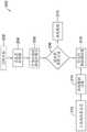
图1是流体管理系统的选定方面的示意图;1 is a schematic diagram of selected aspects of a fluid management system;
图2示出了图1的系统的医疗装置和工作站的选定方面;Figure 2 illustrates selected aspects of the medical device and workstation of the system of Figure 1;
图3示出了图2的医疗装置的选定方面;FIG. 3 illustrates selected aspects of the medical device of FIG. 2;
图4是图2的医疗装置处于原位的示意图;Figure 4 is a schematic view of the medical device of Figure 2 in its original position;
图5是示出了图1的系统的加热器组件和盒的选定方面的局部透视图;5 is a partial perspective view showing selected aspects of the heater assembly and cassette of the system of FIG. 1;
图6-9是说明性的原始数据曲线;Figures 6-9 are illustrative raw data curves;
图10是使用和执行数据信号的自适应滤波的方法的说明性流程图;10 is an illustrative flow diagram of a method of using and performing adaptive filtering of a data signal;
图11是执行数据信号的自适应滤波的方法的说明性流程图;并且11 is an illustrative flow diagram of a method of performing adaptive filtering of a data signal; and
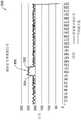
图12-13示出了滤波数据曲线。Figures 12-13 show the filtered data plots.
虽然本发明服从各种修改和替代形式,但是其特定情况已经通过示例方式在附图中示出并且将被详细描述。然而,应该理解的是,意图不是将本发明的多个方面限制于所描述的特定实施例。相反,意图是覆盖落于本发明的精神和范围内的所有变型、等同方案和替代方案。While the invention is amenable to various modifications and alternative forms, specific aspects thereof have been shown by way of example in the drawings and will be described in detail. It should be understood, however, that the intention is not to limit aspects of the invention to the particular embodiments described. On the contrary, the intention is to cover all modifications, equivalents, and alternatives falling within the spirit and scope of the invention.
具体实施方式Detailed ways
对于以下定义的术语,这些定义将适用,除非在权利要求书中或在本说明书中的其它地方给出了不同的定义。For terms defined below, these definitions shall apply unless a different definition is given in the claims or elsewhere in this specification.
所有数值在本文中都被假定为被术语“大约”修饰,不管是否被明确地指出。术语“大约”通常是指一定范围的数字,其将被本领域的技术人员认为等同于所举值(即,具有相同的功能或结果)。在许多情况下,术语“大约”可以指示为包括被四舍五入到最接近有效数字的数字。All numerical values herein are assumed to be modified by the term "about," whether or not explicitly stated. The term "about" generally refers to a range of numbers that one of skill in the art would consider equivalent to the recited value (ie, having the same function or result). In many instances, the term "about" may be indicated to include the number rounded to the nearest significant figure.
通过端点对数值范围的列举包括处于该范围内的所有数字(例如1-5包括1、1.5、2、2.75、3、3.80、4和5)。The recitation of numerical ranges by endpoints includes all numbers within that range (eg, 1-5 includes 1, 1.5, 2, 2.75, 3, 3.80, 4, and 5).
尽管公开了属于各种部件、特征和/或规格的一些适当的尺寸、范围和/或值,但是本领域的技术人员通过本公开的启发将理解所需的尺寸、范围和/或值可以偏离被明确地公开的那些。Although some suitable dimensions, ranges and/or values pertaining to various components, features and/or specifications are disclosed, those skilled in the art will understand, in light of this disclosure, that the desired dimensions, ranges and/or values may deviate from the desired dimensions, ranges and/or values those that are explicitly disclosed.
如在本说明书和所附权利要求书中使用的,单数形式“一”、“一个”和“该”包括复数的对象,除非内容另有明确规定。如在本说明书和所附权利要求书中使用的,术语“或”在其意义上通常被采用来包括“和/或”,除非内容另有明确规定。As used in this specification and the appended claims, the singular forms "a," "an," and "the" include plural referents unless the content clearly dictates otherwise. As used in this specification and the appended claims, the term "or" is generally employed in its sense including "and/or" unless the content clearly dictates otherwise.
以下详细描述应该参考附图来阅读,其中不同附图中的相似元件被相同地编号。详细描述和附图(其并不一定按比例进行绘制)示出了例示性实施例而且并不旨在限制本发明的范围。所描绘的说明性实施例仅旨在作为示例。任何说明性实施例的选定特征都可以并入到附加实施例中,除非另有明确的相反说明。The following detailed description should be read with reference to the accompanying drawings, wherein like elements in different figures are numbered the same. The detailed description and drawings, which are not necessarily drawn to scale, show exemplary embodiments and are not intended to limit the scope of the invention. The depicted illustrative embodiments are intended to be examples only. Selected features of any illustrative embodiment may be incorporated into additional embodiments unless expressly stated to the contrary.
比如“近侧”、“远侧”、“前进”、“后退”及其变体等相关术语通常可以相对于装置的用户/操作者/操纵器的各种元件的定位、方向和/或操作来考虑,其中“近侧”和“后退”表示或指更靠近或朝向用户,而“远侧”和“前进”表示或指远离用户或距用户更远。在一些情况下,术语“近侧”和“远侧”可以任意指定,以有助于理解本公开,并且这些情况对于本领域技术人员来说是显而易见的。其它相关术语,比如“上游”、“下游”、“流入”和“流出”,指的是比如身体管腔、血管等管腔内或装置内的流体流动的方向。Related terms such as "proximal", "distal", "advance", "reverse" and variations thereof may generally be relative to the positioning, orientation and/or operation of various elements of the device's user/operator/manipulator Consider, where "proximal" and "backward" mean either closer to or toward the user, and "distal" and "forward" mean either away from or further from the user. In some instances, the terms "proximal" and "distal" may be designated arbitrarily to facilitate understanding of the present disclosure, and such instances will be apparent to those skilled in the art. Other related terms, such as "upstream," "downstream," "inflow," and "outflow," refer to the direction of fluid flow within a lumen, such as a body lumen, blood vessel, or within a device.
用于在柔性输尿管镜检查(fURS)手术(例如输尿管镜检查、经皮肾镜取石术(PCNL)、良性前列腺增生(BPH)、经尿道前列腺切除术(TURP)等)、妇科检查和其它内窥镜手术中使用的一些流体管理系统在与内窥镜装置(比如但不限于LithoVueTM窥镜装置)结合使用时,可以利用来自内窥镜或其它内窥镜装置的压力和/或温度数据来调控身体腔体压力。在医疗手术期间对腔内压力的直接调控可以允许流体管理系统安全地驱动高达600mmHg的系统压力,以确保在手术期间在将工具插入到内窥镜装置的工作通道中时不会出现流体损失。在一些手术中,身体腔体中可能存在血液和/或碎屑,这可能对内窥镜装置的图像质量产生负面影响。通过内窥镜装置的流体流(例如冲洗液)可以用于冲刷身体腔体以提高图像质量。在一些手术中,身体腔体可以相对较小,并且冲洗流体可以持续流动,这可以提高腔内流体压力和/或系统压力(例如流体管理系统本身内的流体压力)。For use in flexible ureteroscopy (fURS) procedures (such as ureteroscopy, percutaneous nephrolithotomy (PCNL), benign prostatic hyperplasia (BPH), transurethral resection of the prostate (TURP), etc.), gynecological examinations and other internal Some fluid management systems used in endoscopic procedures can utilize pressure and/or temperature data from an endoscope or other endoscopic device when used in conjunction with an endoscopic device such as, but not limited to, a LithoVue™ endoscopic device to regulate body cavity pressure. Direct regulation of intraluminal pressure during medical procedures may allow the fluid management system to safely drive system pressures up to 600mmHg to ensure no fluid loss occurs during the procedure when tools are inserted into the working channel of the endoscopic device. In some procedures, blood and/or debris may be present in body cavities, which may negatively affect the image quality of the endoscopic device. Fluid flow (eg, irrigation fluid) through the endoscopic device can be used to flush body cavities to improve image quality. In some procedures, the body cavity may be relatively small, and the irrigation fluid may flow continuously, which may increase the fluid pressure within the cavity and/or the system pressure (eg, within the fluid management system itself).
因为一些腔的体积非常小,并且冲洗流体持续流入到腔中,所以流体的流动可能会在腔中产生高压。在一些情况下,增加的腔内流体压力和/或系统压力可能给患者带来风险。在一些手术中,使用接入护套从腔中生成流出物并且降低压力,但是在许多情况下,不使用接入护套,这反过来可能会在腔中产生非常高的压力。在一些情况下,医生可能无法得知腔中的压力是多少,因此他们可能倾向于保持较低的冲洗流量并且降低他们的图像质量和可视化,以防止腔中出现高压。在一个说明性示例中,人们认为如果肾脏长时间承受高压或短时间瞬时爆发高压,则它可能导致比如肾盂静脉回流等问题以及比如败血症的术后并发症。Because some lumens are very small in volume and the flushing fluid continues to flow into the lumens, the flow of fluid may create high pressures in the lumens. In some cases, increased intraluminal fluid pressure and/or system pressure may present a risk to the patient. In some procedures, access sheaths are used to generate effluent from the lumen and reduce pressure, but in many cases access sheaths are not used, which in turn may create very high pressures in the lumen. In some cases, physicians may not know what the pressure in the cavity is, so they may prefer to keep the irrigation flow low and reduce their image quality and visualization to prevent high pressure in the cavity. In one illustrative example, it is believed that if the kidney is exposed to high pressure for a prolonged period of time or a brief burst of high pressure, it may lead to problems such as venous return of the renal pelvis and postoperative complications such as sepsis.
鉴于压力的变化,压力的测量和监测给数据的可靠解释及其对系统的影响带来了问题。例如,压力曲线可能会振荡,从而导致来自流体管理系统的读数不一致。进一步可想到的是来自流体管理系统的压力读数可以提供脉动信号或具有噪声的信号。可能需要传递压力数据的中断曲线,这将为系统提供更高的可靠性。在一些情况下,流体管理系统还可能需要保护系统压力输出免受系统脉动的影响,因为系统的过度脉动将会降低系统的性能和医生的可用性。期望提供用于与流体管理系统一起使用的可配置数据滤波器的系统和方法。The measurement and monitoring of pressure poses problems for the reliable interpretation of the data and its effect on the system given the changes in pressure. For example, the pressure curve may oscillate, causing inconsistent readings from the fluid management system. It is further contemplated that pressure readings from the fluid management system may provide a pulsatile or noisy signal. Interruption curves for passing pressure data may be required, which will provide greater reliability to the system. In some cases, the fluid management system may also need to protect the system pressure output from system pulsation, which would reduce system performance and physician availability. It would be desirable to provide systems and methods for configurable data filters for use with fluid management systems.
图1是可以用于内窥镜手术(比如fURS手术)的流体管理系统10的示意图。流体管理系统10可以与允许流体流过的医疗装置20联接。在一些实施例中,流体管理系统10和/或医疗装置20可以包括压力传感器。在一些实施例中,医疗装置20可以是LithoVueTM窥镜装置或其它内窥镜。在说明性实施例中,医疗装置20可以包括用于向流体管理系统10提供腔内温度反馈的温度传感器、用于向流体管理系统10提供腔内压力反馈的压力传感器和/或用于向流体管理系统10提供视觉反馈的摄像头。图1中所示的流体管理系统10和/或医疗装置20的一些具体特征和/或附加特征可能没有针对图1进行具体参考,但将在下文和/或结合其它图进行讨论。图1中示出了这些特征,以供上下文使用。1 is a schematic diagram of a
简而言之,流体管理系统10可以包括流入泵50,该流入泵被构造成以一定的流体流量将流体从流体供应源34(例如流体袋等)泵送和/或传输到医疗装置20和/或患者体内的治疗部位。在一些情况下,流体可以在进入医疗装置20之前穿过流体加温系统60。流体的流量、流体的压力、流体的温度和/或其它操作参数可以由控制器48控制或至少部分由该控制器控制。控制器48可以与医疗装置20、流入泵50和/或流体加温系统60进行电子通信(例如有线或无线),以提供控制命令和/或在其间传输或接收数据。例如,控制器48可以从医疗装置20接收数据,比如但不限于压力数据和温度数据。然后,控制器48可以使用从医疗装置20接收的数据来控制流入泵50和/或流体加温系统60的操作参数。Briefly, the
在一些实施例中,控制器48可以被构造成在流量控制模式下以目标流体流量运行。在一些实施例中,在流量控制模式下,控制器48可以被构造成基于一组系统操作参数来控制流入泵50以维持目标流体流量,同时监测从压力传感器传送到控制器48的测量压力。在一些实施例中,当测量的压力达到预设压力阈值时,控制器48可以被构造成自动从流量控制模式切换到压力超控模式,在该压力超控模式中,控制器48自动将流体流量降低到目标流体流量以下,以使测量的压力恢复到预设压力阈值或恢复到预设压力阈值以下。在一些实施例中,控制器48可以被构造成基于一组系统操作参数来控制流入泵50以维持治疗部位处所需的腔内流体压力和/或目标流量。In some embodiments, the
流体管理系统10还包括流体管理单元。说明性的流体管理单元可以包括一个或更多个流体容器支撑件(比如流体供应源吊架32),每个流体容器支撑件支撑一个或更多个流体供应源34(例如一个或更多个流体袋)。在一些实施例中,流体供应源34(例如流体袋)的位置和/或重量可以使用与每个流体供应源吊架32和/或流体容器支撑件相关联和/或可操作联接的远程传感器和/或供应载荷传感器94来检测。控制器48可以与供应载荷传感器94进行电子通信。流体供应源吊架32可以接收各种大小的流体供应源34,比如举例来说1升(L)至5L的流体供应源(例如流体袋)。应当理解的是,可以使用任何数量的流体供应源34。此外,依据手术过程,可以使用任何大小的流体供应源34。在一些实施例中,流体管理单元可以安装到滚动支架上,该滚动支架可以包括杆36和/或基座38。基座38可以包括多个轮子,以便于流体管理单元在使用时容易移动。然而,应当理解的是,依据临床偏好,流体供应源34也可以悬挂在天花板或其它位置。流体供应源吊架32可以从杆36和/或控制器48延伸并且可以包括一个或更多个挂钩,一个或更多个流体供应源34可以悬挂在挂钩上。在一些实施例中,流体管理单元中使用的流体可以是0.9%的盐水。然而,应当理解的是,依据手术过程,可以使用不同粘度的各种其它流体。The
在一些实施例中,流体管理单元可以包括真空泵24以及与收集帘28流体连通的收集容器26。在一些实施例中,真空泵24可以包括多个真空泵。在一些实施例中,收集容器26可以包括多个容器、罐和/或其它接收件,它们可以彼此流体连接和/或与真空泵24流体连接。在一些实施例中,收集帘28可以包括多个收集帘。真空泵24可以与控制器48可操作地连接和/或电子连接。在一些实施例中,真空泵24可以设置邻近和/或接近收集容器26,如图1所示。在一些实施例中,真空泵24可以设置在流体管理系统10内。其它配置也是可想到的。在一些实施例中,收集容器26可以可操作地联接到收集载荷传感器25,以检测收集容器26的放置和/或重量。在具有多个容器、罐和/或其它接收件的实施例中,每个容器、罐和/或接收件可以可操作地联接到相应的收集载荷传感器25。控制器48可以与收集载荷传感器25进行电子通信。In some embodiments, the fluid management unit may include a
流体管理系统10还可以包括一个或更多个用户界面部件,比如触摸屏界面42。触摸屏界面42包括显示器44,并且除了触摸能力之外,该触摸屏界面还可以包括开关或旋钮。在一些实施例中,控制器48可以包括触摸屏界面42和/或显示器44。触摸屏界面42允许用户输入/调节流体管理系统10的各种功能,比如举例来说流量、压力和/或温度。用户还可以配置参数和警报(比如但不限于腔内压力极限、系统压力极限等)、要显示的信息以及手术模式。触摸屏界面42允许用户添加、改变和/或停止使用流体管理系统10内的各种模块化系统。触摸屏界面42还可以用于在各种手术的自动模式和手动模式之间改变流体管理系统10。可想到的是可以使用被构造成接收用户输入的其它系统来代替触摸屏界面42或作为该触摸屏界面的补充。
触摸屏界面42可以被构造成包括类似按钮的可选区域和/或可以提供类似于物理按钮的功能,如本领域的技术人员所理解的。显示器44可以被构造成示出与流体管理系统10中所包括的模块化系统和装置相关的图标。显示器44还可以包括流量显示。流量显示可以基于用户在手术之前所设定的流量的期望阈值或基于公知的常用值等来确定。在一些实施例中,可以通过触摸触摸屏界面42的相应部分来调节操作参数。如果参数(例如流量、压力、温度等)高于或低于预定的阈值和/或范围,则触摸屏界面42还可以显示视觉警告和/或声音警报。触摸屏界面42还可以被构造成显示流体供应源34中剩余的流体量和/或用户在手术期间可能发现有用的任何其它信息。在一些实施例中,流体管理系统10还可以包括另外的用户界面部件,比如可选的脚踏板46、加热器用户界面、流体控制界面或用于手动控制各种模块化系统的其它装置。例如,可选的脚踏板46可以用于手动控制流量。标题为“AUTOMATED FLUID MANAGEMENT SYSTEM”的共同受让美国专利申请公开No.2018/0361055中描述了一些说明性的显示器和其它用户界面部件,该申请的全部公开内容通过引用并入本文。The
触摸屏界面42可以可操作地连接到控制器48或者可以是该控制器的一部分。控制器48可以是计算机、平板计算机或其它处理装置。控制器48可以可操作地连接到一个或更多个系统部件,比如举例来说流入泵50、流体加温系统60、流体不足管理系统等。在一些实施例中,这些特征可以集成到单个单元中。控制器48能够并且被构造成执行各种功能,比如计算、控制、运算、显示等。控制器48还能够跟踪和存储与流体管理系统10及其每个部件的操作相关的数据。在说明性实施例中,控制器48包括有线和/或无线网络通信能力(比如以太网或Wi-Fi),控制器48可以通过这些能力连接到例如局域网。控制器48还可以接收来自流体管理系统10的一个或更多个传感器的信号。在一些实施例中,控制器48可以与数据库通信,以获得最佳实践建议并且维护可以在显示器44上显示给用户的患者记录。The
流体管理系统10可以由用户基于手术、患者特性等在不同模式之间进行选择。例如,不同的模式可以包括但不限于限制模式、通知模式等。一旦用户选择了模式,所选的系统参数(比如目标流体流量、腔内流体压力极限、系统流体压力极限、流体不足和/或温度)可以经由触摸屏界面42和/或显示器44提供给用户和/或由用户输入。可以预先确定特定模式的示例性参数,并且使用例如软件将其加载到控制器48上。因此,当用户从触摸屏界面42的显示器44上的初始显示中选择手术时,可以将这些已知参数从控制器48加载到流体管理系统10的各种部件,比如但不限于流入泵50、流体加温系统60、流体不足管理系统等。流体管理系统10也可以由用户在自动控制和手动控制之间进行选择。例如,对于某些手术,用户可能希望手动调节流体流量、流体压力和/或其它参数。一旦用户在例如触摸屏界面42上选择了手动控制,用户可以经由其它手动界面(比如,例如可选的脚踏板46)来调节流体流量或流体压力。如果用户选择自动控制,则可以提示用户经由触摸屏界面42选择或输入正在使用的医疗装置20,使得控制器48可以确定使用哪些数据和/或参数来促进对流体管理系统10的控制。在一些实施例中,流体管理系统10可以被构造成验证所选的医疗装置20实际上正在被使用。The
在一些实施例中,流体管理系统10可以包括视觉软件或图像识别和分析软件。例如,医疗装置20可以包括摄像头70(例如图2和图4)。在一些实施例中,控制器48可以被构造成包括视觉软件/图像识别软件,这些软件可以基于亮度(例如光监测)、对比度或颜色像素的变化来检测视觉噪声。如果确定提供给控制器48的图像不够清晰或锐利,则流体管理系统10可以临时增加流体流量或流体压力,以将碎屑从治疗部位冲刷出去,从而使图像变得清晰/锐利。流体流量或流体压力可以手动或自动增加一段临时时间(例如预定的时间段)或直到认为视野足够清晰。这种临时的增加确保流体流量或流体压力增加的时间受到限制,以确保腔内压力不会超过安全极限。In some embodiments,
例如,流体管理系统10可以识别冲洗液中的红色色调(血液的迹象)并且向流入泵50发送信号,以将流体流量增加到目标流体流量以上,直到血液从视野中清除。替代地,控制器48可以在显示器44上提供视觉警告或者向医生或护士提供声音警告,从而表明检测到了浑浊视图,然后用户可以手动调节流体流量。在另一个示例中,在存在大量碎屑的情况下,从碎屑反射的光可以使图像显著变亮。在这种情况下,控制器48检测到这种异常的亮度并且向流入泵50发送信号,以增加流体流量,从而冲走和/或去除碎屑。一旦反射的光随着碎屑被冲出视觉系统的视野而减少,流入泵50由控制器48控制以降低流体流量。在一些情况下,医生可以为可见度创建一个基线水平,在该基线水平上他或她更喜欢启动流体的现场清理流并且在手术之前经由触摸屏界面42将这些参数输入到流体管理系统10中。一旦创建了基线,流体管理系统10可以监测图中的视觉馈送变化并且根据需要自动调节流体流量。For example, the
为了调节通过流体管理系统10的流体流量或流体压力,流体管理单元可以包括一个或更多个加压或流量生成装置,比如流入泵50。在一些实施例中,流入泵50可以是蠕动泵。在一些实施例中,流入泵50可以包括多个泵或多于一个泵。流入泵50可以是电驱动的并且可以从线源(比如壁装插座)、外部或内部电存储装置(比如一次性电池或可充电电池)和/或内部电源接收电力。流入泵50可以在足以以目标压力(比如举例来说,5mmHg至50mmHg)和/或以目标流体流量输送流体的任何期望速度下运行。如本文所述,可以基于例如治疗部位内的腔内压力读数和/或温度读数和/或来自医疗装置20的视觉反馈来自动调节流入泵50。流入泵50也可以经由例如可选的脚踏板46、触摸屏界面42或单独的流体控制器进行手动调节。虽然没有明确示出,但是流体控制器可以是单独的用户界面,包括允许用户增加或减少流入泵50的速度和/或输出的按钮。替代地,流体控制器可以并入到主处理装置中并且经由触摸屏界面42接收输入。在一些实施例中,流体管理系统10可以包括具有不同流动能力的多个泵。在一些实施例中,流量传感器77(例如图5)可以位于流入泵50之前和/或之后,以测量实际的流体流量。流量传感器77可以可操作地连接到控制器48,并且控制器48可以使用来自流量传感器77的数据来改变选定的系统参数。To regulate fluid flow or fluid pressure through the
流体在任何给定时间下的流体流量和/或流体压力可以显示在显示器44上,以允许手术室(OR)看到任何变化。如果手术室人员注意到流体流量和/或流体压力的变化过高或过低,则用户可以手动将流体流量和/或流体压力调节回优选水平。例如,当医生将工具插入到医疗装置20的工作通道中或从其中取出工具时,可能发生这种情况。流体管理系统10还可以基于先前设定的参数来监测和自动调节流体流量和/或流体压力,如本文所述。当手动提供流体流动时,比如通过注射器辅助注射冲洗液时,该特征也是可能是有益的。The fluid flow and/or fluid pressure of the fluid at any given time can be displayed on the
在一些实施例中,流体管理系统10可以基于测量的腔内温度和/或测量的压力自动调节流体流量和/或流体压力,例如当测量的压力达到预设的压力阈值时。在一些实施例中,测量的压力可以是在治疗部位内测量的腔内压力,并且预设压力阈值可以是腔内压力极限。可以使用安装在与流体管理系统10结合使用的医疗装置20(例如图2)上的温度传感器72和/或压力传感器74来原位测量腔内温度和/或腔内压力。在一些实施例中,测量的压力可以是在流体管理系统10内测量的系统压力,并且预设压力阈值可以是系统压力极限。可以使用设置在流体管理系统10内的压力传感器67(例如图5)在流体管理系统10内测量系统压力。在一些实施例中,流体管理系统10可以包括压力监测软件,使得用户可以将流入泵50配置为由流体管理系统10自动启动、停止和/或调节速度,以将输送到治疗部位的流体压力维持在目标压力和/或预定压力范围内。例如,压力传感器74可以检测治疗部位(例如肾脏或子宫)内的腔内压力并且基于测量的腔内(例如肾脏内或子宫内)压力自动更改流体管理系统10内的流体流量和/或流体压力。如果腔内压力太高,则流体管理系统10可以降低流体流量和/或流体压力,如果腔内压力太低,则流体管理系统10可以增加流体流量和/或流体压力。In some embodiments,
图2-4示出了可以与流体管理系统10结合使用的医疗装置20的各个方面。在所示的实施例中,医疗装置20可以是输尿管镜,比如LithoVueTM窥镜。然而,可以使用其它医疗装置(比如另一种内窥镜)来作为输尿管镜的补充或替代。医疗装置20可以被构造成经由细长轴76将流体从流体管理系统10输送到治疗部位,该细长轴被构造成接近患者体内的治疗部位。在一些实施例中,流入泵50可以与细长轴76流体连通。细长轴76可以包括一个或更多个工作管腔,用于接收通过其中的流体流或其它医疗装置。医疗装置20经由一个或更多个供应管线78(例如管)连接到流体管理系统10,例如如图1和图4所示。2-4 illustrate various aspects of
在一些实施例中,医疗装置20可以经由有线连接79与工作站81进行电子通信。工作站81可以包括触摸面板计算机83、用于接收有线连接79的接口盒85、推车87和电源89以及其它特征。在一些实施例中,接口盒85可以配置有与流体管理系统10的控制器48的有线或无线通信连接91。触摸面板计算机83可以至少包括显示屏和图像处理器。在一些实施例中,工作站81可以是多用途的部件(例如用于多于一个的手术),而医疗装置20可以是单用途的装置,尽管这不是必需的。在一些实施例中,工作站81可以省略,并且医疗装置20可以直接电耦合到流体管理系统10的控制器48。In some embodiments,
在一些实施例中,从流体管理系统10到医疗装置20的一个或更多个供应管线78可以由有助于抑制流入泵50所产生的蠕动运动的材料形成。在一些实施例中,供应管线78可以由直径小于或等于1/16英寸(1.5875毫米)的小直径管形成。然而,应当理解的是,管的大小可以基于应用而变化。供应管线78和/或管可以是一次性的,并且被设置为无菌的和备用的。不同类型的管可以用于流体管理系统10内的各种功能。例如,一种类型的管可以用于对医疗装置20的流体加热和流体流的控制,而另一种类型的管可以用于在体内和/或治疗部位内的冲洗。In some embodiments, one or more of the
如图2所示,医疗装置20可以包括靠近细长轴76的远端80的一个或更多个传感器。例如,医疗装置20可以包括位于细长轴76的远侧末端处的压力传感器74,以测量治疗部位内的腔内压力。医疗装置20还可以包括其它传感器,比如举例来说温度传感器72、用于检测应力的光纤布拉格光栅光纤75和/或天线或电磁传感器93(例如位置传感器)。在说明性实施例中,医疗装置20的远端80还可以包括至少一个摄像头70,以在触摸面板计算机83的显示屏上向用户提供视觉反馈。在另一个实施例中,医疗装置20可以包括具有不同通信要求或协议的两个摄像头70,使得每个摄像头70可以向用户中继不同的信息。当这样设置时,用户可以通过触摸屏界面42和/或触摸面板计算机83随意在摄像头70之间来回切换。虽然没有明确示出,但细长轴76可以包括一个或更多个工作管腔,用于接收流体或其它医疗装置。As shown in FIG. 2 , the
在一些实施例中,可以在使用期间跟踪细长轴76的远端80的位置。例如,测绘和导航系统可以包括操作台(或其它程序或检查台或椅子等),该操作台被构造成充当电磁发生器或起到电磁发生器的作用,以生成已知几何形状的磁场。替代地或附加地,可以提供与操作台分离的电磁发生器。操作台和/或电磁发生器可以耦合到控制单元,该控制单元可以包括处理器、存储器、显示器和输入器件等特征。位置传感器(例如电磁传感器93等)或其它天线可以并入到医疗装置20的细长轴76的远端80中。位置传感器可以被配置用于感测位置传感器在测绘和导航系统的磁场中的位置。在一些实施例中,位置传感器可以电耦合到工作站81。当位置传感器处于磁场中时,位置传感器的位置可以相对于电磁场源(例如操作台和/或电磁发生器)以数学方式确定。工作站81和控制单元可以通信,以确定位置传感器相对于患者的位置。In some embodiments, the position of the
医疗装置20包括与细长轴76的近端联接的手柄82。手柄82可以具有流体流动开/关的开关84,该开关允许用户控制流体何时流过医疗装置20并且进入治疗部位。手柄82可以进一步包括执行其它各种功能的其它按钮86。例如,在一些实施例中,手柄82可以包括用于控制流体温度的按钮。应当理解的是,虽然示例性实施例描述了输尿管镜,但是上文详细描述的特征也可以直接集成到膀胱镜、内窥镜、宫腔镜或实际上具有成像能力的任何装置中。在一些实施例中,医疗装置20还可以包括排液端口88,该排液端口可以连接到排液系统。标题为“AUTOMATED FLUID MANAGEMENT SYSTEM”的共同受让美国专利申请公开No.2018/0361055中描述了一些说明性的排液系统,该申请的公开内容通过引用并入本文。The
在一些实施例中,控制器48可以被构造成当细长轴76的远端80设置在患者体内时计算流体不足,该流体不足表示在手术期间损失、被患者吸收和/或以其它方式未考虑的流体。在一些实施例中,控制器48可以配置为当总流体不足达到预设流体不足极限时通知用户。在一些实施例中,控制器48可以配置为当总流体不足达到预设流体不足极限时停止流入泵50和/或真空泵24。在一些实施例中,控制器48可以被构造成当输注的流体总量达到预设的流体输注极限时通知用户。在一些实施例中,控制器48可以被构造成当输注的流体总量达到预设的流体输注极限时停止流入泵50和/或真空泵24。In some embodiments, the
在一些实施例中,控制器48可以被构造成使用例如供应载荷传感器94、天平或其它合适的器件通过重量来监测流体供应源34中的流体量。控制器48可以使用供应载荷传感器94来确定附接到流体供应源吊架32上的流体供应源34的重量,以将流体供应源34中的初始流体量与流体供应源34中剩余的当前流体量进行比较。供应载荷传感器94的读数可以在显示器44上向用户示出。随着手术的进行,供应载荷传感器94的读数可以实时更新,以提醒医生在流体供应源34中还剩多少流体,然后可以使用该量来确定有多少流体已经输注到了患者体内。在一些实施例中,可以示出流体供应源34中剩余的流体量。例如,当流体供应源34中留有10%的流体时,可以在显示器44上示出带有声音信号的警告。在一些实施例中,供应载荷传感器94可以经由无线(例如Wi-Fi)信号连接到显示器44。在一些实施例中,供应载荷传感器94可以经由硬线连接而连接到显示器44。在手术期间,如果流体供应源34变空,则可以利用满的或未使用的流体供应源34来替换。In some embodiments,
类似地,控制器48可以被构造成使用例如收集载荷传感器25、天平或其它合适的器件通过重量来监测收集容器26中的流体量。控制器48可以使用收集载荷传感器25来确定收集容器26的重量,以将收集容器26中的初始流体量与收集容器26中的当前流体量进行比较。收集载荷传感器25的读数可以在显示器44上向用户示出。随着手术的进行,收集载荷传感器25的读数可以实时更新,以提醒医生在收集容器26中有多少流体,然后可以使用该量来确定从患者体内和/或收集帘28收集了多少流体。在一些实施例中,可以示出收集容器26中的流体量。例如,当收集容器26中留有10%的初始空体积时,可以在显示器44上示出带有声音信号的警告。在一些实施例中,收集载荷传感器25可以经由无线(例如Wi-Fi)信号连接到显示器44。在一些实施例中,收集载荷传感器25可以经由硬线连接而连接到显示器44。在手术期间,如果收集容器26变满,则可以将该收集容器清空并且重新投入使用,或者可以用空的收集容器替换该收集容器26。Similarly,
在一些实施例中,流体管理系统10可以包括流体加温系统60,如图5所示,用于加热要输送给患者的流体。流体加温系统60可以包括加热器62和加热器盒64。加热器盒64可以被构造成单次使用的加热器盒64,而加热器62可以在多个手术中重复使用。例如,加热器盒64可以隔离流体流动,使得加热器62可以在维护最少的情况下重复使用。加热器盒64可以由例如聚碳酸酯或任何高热等级的生物相容塑料形成,并且形成为单个整体和/或单片件或彼此永久结合的多个件。在一些实施例中,加热器盒64可以包括位于加热器盒64的横向侧面的流体入口端口61和流体出口端口63。流体入口端口61和流体出口端口63可以各自被构造成联接到流体管理系统10的供应管线78。例如,流体入口端口61可以联接流体供应源34和流体加温系统60(经由流入泵50),而流体出口端口63可以联接流体加温系统60和医疗装置20,各自经由供应管线78。In some embodiments, the
在一些实施例中,加热器盒64可以包括沿着通道的内部流动路径,流体可以通过该内部流动路径从流体入口端口61流向流体出口端口63。加热器盒64可以包括一个流体路径或多个流体路径。在一些实施例中,通道可以穿过承受器66,该承受器可以允许经由感应加热来加热流体。当加热器盒64与加热器62耦合时,承受器66可以被构造成位于感应线圈68内。根据需要,也可以使用其它流体加温系统配置和方法。例如,加热器62可以包括一个或更多个热源,比如举例来说使用电能的压板系统或供应管线78中的内嵌线圈。加热可以根据流体管理系统10的具体应用中所需的流量进行具体设计和定制。标题为“AUTOMATEDFLUID MANAGEMENT SYSTEM”的共同受让美国专利申请公开No.2018/0361055中描述了一些说明性的流体加温系统,该申请的公开内容通过引用并入本文。In some embodiments,
虽然没有明确示出,但是流体加温系统60可以包括与触摸屏界面42分离的加热器用户界面。加热器用户界面可以只是提供加热器62内部温度的数字显示的显示屏。在另一个实施例中,用户界面还可以包括温度调节按钮,以增加或降低加热器62的温度。在该实施例中,加热器用户界面和/或显示屏可以指示加热器62的当前温度以及要达到的目标温度。注意,从流体加温系统60输出的所有信息可以直接传输到显示器44,因此不需要加热器用户界面。Although not explicitly shown,
流体加温系统60可以包括一个或更多个传感器,这些传感器被构造成监测流过其中的流体。例如,温度传感器65可以安装在流体加温系统60中,以便该温度传感器检测流经加热器盒64的流体的温度。温度传感器65可以位于流体入口端口61和/或流体出口端口63之处或附近。在一些实施例中,可以安装温度传感器65,使得该温度传感器在流体进入承受器66之前和流体离开承受器66之后检测流经加热器盒64的流体的温度。在一些实施例中,额外的传感器可以位于承受器66的中间部分处,使得该额外的传感器检测加热器盒64中流体的温度升高的进程。温度传感器65可以向显示器44远程发送任何信息,或者该温度传感器可以向加热器用户界面和/或其显示屏发送信息,如果这样设置的话。在另一个实施例中,温度传感器65可以与加热器用户界面(如果设置的话)硬连线,然后该加热器用户界面能够将所需的信息远程传输到显示器44。替代地或附加地,温度传感器65可以硬连线到控制器48上和/或与该控制器硬连线。
加热器62可以进一步包括被构造成监测系统压力的压力传感器67和/或被构造成监测流经系统的流体是否有气泡的气泡传感器69。加热器盒64可以包括相应的压力传感器接口71和气泡传感器接口73,当加热器盒64与流体加温系统60联接时,该压力传感器接口和气泡传感器接口分别允许压力传感器67和气泡传感器69监测流经加热器盒64的流体。压力传感器67和/或气泡传感器69可以向控制器48、显示器44远程发送任何信息,和/或该压力传感器和/或气泡传感器可以向加热器用户界面和/或其显示屏发送信息,如果这样设置的话。在另一个实施例中,压力传感器67和/或气泡传感器69可以与加热器用户界面(如果设置的话)硬连线,然后该加热器用户界面能够将所需的信息远程传输到显示器44。替代地或附加地,压力传感器67和/或气泡传感器69可以硬连线到控制器48上和/或与该控制器硬连线。
从医疗装置20的压力传感器74和/或从流体管理系统10内的压力传感器67接收的压力信号可能波动很大。在一些情况下,波动可能是由于流入泵50处的脉动引起的流体中的脉冲。脉冲可以依据流体的流量而变化。图6-9示出了可能出现在流体管理系统中的一些示例性压力信号曲线。然而,这些曲线并不代表所有可能的压力信号曲线。不同的压力信号曲线可以各自包括在医疗装置20的使用期间控制腔内压力和/或输送压力的独特障碍。The pressure signal received from the
图6示出了慢速脉动的示例性压力曲线100。在这种情况下,当使用压力信号的正常平均值时,可能只能捕获一部分数据。这可能导致高于实际平均值或低于实际平均值的值被用作压力信号,这取决于所分析的数据的秒数。图7示出了快速脉动的示例性压力曲线110。如果流体管理系统10试图使用快速脉冲压力信号来控制流体的流动,则控制器48可以跟踪压力信号的振荡并且在控制器48跟踪不稳定的设定点时引起系统10内的进一步振荡。图8示出了具有长尖峰或压力增加的快速脉动的示例性压力曲线120。在该示例中,曲线120示出了压力信号的明显且持续的增加122,这需要由控制器48来识别和辨认。压力增加和尖峰122的持续时间对于系统10的控制很重要,并且不应被视为噪声。图9示出了不包括脉动但包括压力信号明显且持续的增加132的示例性压力曲线130。压力曲线130示出了没有脉动的高噪声信号(例如压力信号中的许多尖峰和下降不是由于流体的脉动而引起的)。这可能是由信号中的噪声引起的。在所示的压力曲线130中,压力信号的信噪比(SNR)为0.47。这种类型的压力曲线可能表明压力信号的质量处于不可接受的水平。FIG. 6 shows an
为了补偿压力信号数据的变化性质,可以使用可配置的或自适应的数据滤波器,以对压力信号数据执行数字信号处理(DSP)并且向FMS 10的子系统提供剖析数据。自适应数据滤波器可以用于独立于FMS 10的其它程序或子系统来分析压力信号数据。因此,可以以各种形式来分析相同的压力数据集,以便为FMS10的特定子系统或使用应用提供最准确的数据。此外,可以使用类似的自适应滤波器来分析其它数据信号。例如,FMS 10可以测量和使用流体供应源34的重量,以提供满足流入泵50或其它子系统的控制逻辑需求的输出。To compensate for the varying nature of the pressure signal data, configurable or adaptive data filters may be used to perform digital signal processing (DSP) on the pressure signal data and provide profiling data to the subsystems of the
图10是使用和执行压力信号的自适应滤波的方法200的说明性流程图。虽然方法200是关于压力信号描述的,但是应当理解的是,该方法可以应用于用于向FMS 10的各种部件的控制逻辑提供输入的其它数据信号。例如,流体供应源34的重量、流体的流量、流体的温度等仅仅是可以使用本文所述的自适应滤波技术进行滤波的一些附加数据信号。10 is an illustrative flow diagram of a
说明性方法200可以由存储在控制器48和/或工作站81的存储器中的控制逻辑来执行。图10所示的说明性方法200具有两个在中间相遇的起始点。在第一起始点处,启动任务(例如发出控制命令)以请求以预定的时间间隔采集或收集数据信号,如方框202所示。例如,可以每毫秒请求或捕获一次压力数据信号。这只是一个示例。可以根据需要或适当地使用其它数据收集频率或间隔。可以在例如安装在医疗装置20上的压力传感器74处或者适当地在其它压力传感器处收集压力数据信号。在一些情况下,控制器48和/或工作站81可以在经由用户界面42、83接收到来自医生的请求时开始收集数据。在其它实施例中,控制器48和/或工作站81可以被编程为在预定时间或当FMS 10或其子系统被开启时自动启动数据信号的收集。在启动数据收集任务之后,采集原始数据信号(比如但不限于压力数据信号),如方框204所示。如方框206所示,将原始数据信号存储在缓冲器中。原始数据信号被存储在缓冲器中,直到采集到预定最小数量的样本。因此,控制器48和/或工作站81继续以预定的时间间隔采集数据信号,直到滤波缓冲器完成(例如具有最小数量的数据样本),如方框208所示。一旦完成滤波缓冲,控制器48和/或工作站81可以被构造成使用来自FMS 10的一个或更多个子系统的原始数据信号和设定来创建剖析数据,如方框210所示。剖析数据可以基于从将使用该数据的子系统接收的配置信息,这将在本文中更详细地描述。图6-9中示出了一些说明性的剖析数据。如将在本文中更详细描述的,可以使用自适应数据滤波器对该剖析数据进行滤波。可想到的是可以分析(或剖析)相同的数据集,以便为特定子系统提供最准确的数据。例如,多于一个的子系统可以利用压力数据信号。然而,每个子系统可以在关注数据信号的不同方面的情况下最佳地运行。
在第二起始点处,将使用原始和/或滤波后的数据信号的子系统包括编程或被构造成接收用户输入,以确定如何对数据进行剖析的配置,如方框212所示。子系统可以请求以各种方法对数据信号进行分析或剖析。这些请求可以包括但不限于:原始数据的最大值、原始数据的最小值、原始数据的平均值、原始数据的SNR、滤波数据的最大值、滤波数据的最小值、滤波数据的平均值、频率、尖峰检测、峰间脉动等。如方框214所示,子系统将配置或设定滤通给剖析数据引擎。这些设定存储在剖析数据引擎中并且用于生成剖析数据。如方框216所示,剖析数据可以用作原始数据信号或使用自适应数据滤波器进行处理。At a second starting point, the subsystem that will use the raw and/or filtered data signal includes a configuration programmed or configured to receive user input to determine how to parse the data, as represented by
图11是利用自适应数据滤波器处理数据信号216的方法的说明性流程图。如方框218所示,该方法启动子系统请求对数据进行剖析和滤波。作为请求的一部分,子系统可以提供将被并入到数据分析中的许多设定。说明性方法216可以由存储在控制器48和/或工作站81的存储器中的控制逻辑来执行。通常,控制逻辑是用于数据信号曲线的数字信号处理的算法或滤波器。当滤波器根据从子系统接收的输入和/或基于原始数据本身处理不同的信号时,该滤波器可以适应或改变。滤波器可以对剖析的数据执行多次滤通。每次滤通可以针对信号的不同特征来监测和分析信号。在一些情况下,如果控制逻辑确定不需要特定的滤通,则可以跳过该特定的滤通。因此,滤波器可以基于被分析的信号和/或基于将利用数据信号的子系统来适应或改变。11 is an illustrative flow diagram of a method of processing a
首先,控制逻辑可以确定是否需要从数据信号曲线中去除噪声,如方框220所示。如果需要去除噪声,则基于给定分析所允许的噪声容限来调节滤波器(例如控制逻辑改变滤波器的设定)。可想到的是噪声容限由请求数据的子系统提供。然后,如方框222所示,滤波器从剖析的原始数据中去除任何高频尖峰(例如振荡),以提供平滑的信号。这可以从原始数据中去除由于噪声引起的任何微小波动。如方框224所示,然后,滤波器可以确定平滑信号内的噪声计数。如方框226所示,然后,噪声计数可以用于确定信噪比(SNR)。一旦确定了SNR,或者如果控制逻辑确定不需要噪声去除,则控制逻辑可以确定是否需要脉动监测,如方框228所示。First, the control logic may determine whether noise needs to be removed from the data signal curve, as represented by
如果需要脉动监测,则控制逻辑将首先确定信号的频率,如方框230所示。例如,滤波器可以确定数据集中的拐点并且将其用作滤波的基础。如方框232所示,然后,控制逻辑可以确定峰间脉动。在该步骤期间,在每个拐点之上或在每个拐点处,将监测最后一个拐点和随后的拐点之间的持续时间,以确定数据集内的信号脉动的频率。滤波器还可以监测每个拐点内的脉动的数据集,从而监测最大的、最小的和平均的峰间偏差。最大的峰间偏差将用于确定系统的脉动。在一些情况下,如果峰间偏差超过预定阈值,则这可能会生成警告。If pulsation monitoring is required, the control logic will first determine the frequency of the signal, as represented by
如方框234所示,然后,控制逻辑可以按顺序(例如一个接一个)对每个振荡进行平均。这可以为子系统提供平滑值以供使用。如方框236所示,然后,控制逻辑确定滤波曲线的最大值、最小值和/或平均值。然后,子系统的控制系统可以使用这些值来确定FMS 10的实际压力值。可想到的是即使不需要脉动监测,如果认为其它通道是不必要的,则控制逻辑也可以使用原始信号或滤波信号(在任何滤波滤通之后)的最大值、最小值和/或平均值。As represented by
一旦确定了最大值、最小值和/或平均值,或者如果控制逻辑确定不需要脉动监测,则控制逻辑可以确定是否需要尖峰监测,如方框238所示。如果需要尖峰监测,则控制逻辑将分析剖析的数据并且确定在数据集内是否存在尖峰,如方框240所示。在一些情况下,可以对数据集的子集执行尖峰监测,并且该尖峰监测可以用于确定压力(或其它变量)是否突然增加或减少。一旦控制逻辑确定是否已经出现尖峰或者是否不需要尖峰监测,则滤波过程可以结束,如方框242所示。然后,最初请求数据的子系统可以使用滤波数据曲线来控制FMS 10的各个方面。例如,响应于持续的压力增加,FMS 10可以降低流体流量。这只是一个示例。Once the maximum, minimum, and/or average values are determined, or if the control logic determines that pulse monitoring is not required, the control logic may determine whether spike monitoring is required, as represented by
关于图11描述的自适应的或可变的滤波方法可以被任何子系统用来确定接收信号的性质,以提供快速且可靠的结果。这可以允许FMS 10对系统中的变化做出快速和安全的反应。在一些情况下,SNR可以为FMS 10提供检测系统故障的手段并且警告系统和/或操作者压力读数(或其它变量)可能不准确,应该解决该问题。在一个示例中,自适应滤波器216可以用于在开始手术之前确定SNR。这可以在传感器不能正常工作的情况下帮助保护FMS 10和/或患者免受潜在伤害。SNR也可以在制造中用作基线测试,以确保布线和屏蔽正确。The adaptive or variable filtering method described with respect to Figure 11 can be used by any subsystem to determine the properties of the received signal to provide fast and reliable results. This may allow the
自适应滤波器216还可以提供用于监测泵运行的手段,并且该自适应滤波器可以用于利用信号的频率来确定泵的旋转速度。这也可以允许系统在手术期间监测泵性能的变化。进一步可想到的是尖峰检测可以允许控制系统采取快速行动以保护系统免受可能发生的过压状况。The
在一些情况下,自适应滤波器216可以允许控制器48和/或工作站81监测输入信号的越界状况。例如,可以针对超过预定最大阈值或低于预定最小阈值的信号来监测原始数据曲线和/或滤波曲线。预定范围之外的原始数据曲线和/或滤波曲线可以指示传感器故障或失灵,并且可以将警告发送到FMS 10的用户界面或显示器44和/或以其它方式提供给其操作者。In some cases,
进一步可想到的是自适应滤波器216可以允许控制器48和/或工作站81分析输入信号的变化率。例如,可以针对超过预定最大阈值或低于预定最小阈值的变化率来监测原始数据曲线和/或滤波曲线。预定范围之外的变化率可以指示不稳定的信号,并且可以将警告发送到FMS 10的用户界面或显示器44和/或以其它方式提供给其操作者。It is further contemplated that
图12示出了包括原始数据信号302及其相应滤波数据信号304的曲线图300。在所示实施例中,以平均最大值作为来自子系统的请求来分析原始数据信号302。与原始数据信号302相比,滤波数据信号304具有降低的噪声,这在滤波数据信号304的更平滑的线中可以看出。此外,数据中的尖峰306对于FMS10和/或子系统是可见的(例如没有被数据滤波器移除)。图13示出了包括滤波数据信号352的另一个曲线图350。在所示实施例中,自适应滤波器216已经从信号中去除了所有噪声,同时尖峰数据对于FMS 10和/或子系统保持可见。FIG. 12 shows a
本领域的技术人员将认识到,除了本文描述和设想的具体实施例之外,本发明可以以多种形式体现。因此,可以在形式和详情上发生偏差,而不背离如在所附权利要求书中描述的本发明的范围和精神。Those skilled in the art will appreciate that the present invention may be embodied in various forms other than the specific embodiments described and contemplated herein. Accordingly, departures may be made in form and detail without departing from the scope and spirit of the invention as described in the appended claims.
Claims (15)
Translated fromChineseApplications Claiming Priority (3)
| Application Number | Priority Date | Filing Date | Title |
|---|---|---|---|
| US202062982384P | 2020-02-27 | 2020-02-27 | |
| US62/982,384 | 2020-02-27 | ||
| PCT/US2021/019949WO2021174027A1 (en) | 2020-02-27 | 2021-02-26 | Adaptive pressure control filter for a fluid management system |
Publications (1)
| Publication Number | Publication Date |
|---|---|
| CN115176318Atrue CN115176318A (en) | 2022-10-11 |
Family
ID=75143733
Family Applications (1)
| Application Number | Title | Priority Date | Filing Date |
|---|---|---|---|
| CN202180017423.2APendingCN115176318A (en) | 2020-02-27 | 2021-02-26 | Adaptive pressure control filter for fluid management systems |
Country Status (8)
| Country | Link |
|---|---|
| US (1) | US20210268182A1 (en) |
| EP (1) | EP4111465A1 (en) |
| JP (2) | JP7454694B2 (en) |
| KR (2) | KR102840079B1 (en) |
| CN (1) | CN115176318A (en) |
| AU (2) | AU2021228722B2 (en) |
| CA (1) | CA3172882A1 (en) |
| WO (1) | WO2021174027A1 (en) |
Cited By (2)
| Publication number | Priority date | Publication date | Assignee | Title |
|---|---|---|---|---|
| CN116584883A (en)* | 2023-06-05 | 2023-08-15 | 中国人民解放军陆军军医大学第二附属医院 | Water flushing device for pedal ureteroscope |
| CN119207752A (en)* | 2024-11-26 | 2024-12-27 | 上海宇度医学科技股份有限公司 | A method and system for hysteroscopic real-time liquid pressure stabilization control |
Families Citing this family (3)
| Publication number | Priority date | Publication date | Assignee | Title |
|---|---|---|---|---|
| CN114945392A (en) | 2019-11-08 | 2022-08-26 | 瑟梅德斯有限责任公司 | Fluid management system and method |
| DE102021113782B3 (en)* | 2021-05-27 | 2022-06-09 | Vivonic Gmbh | Measuring device with a sensor in a hollow storage vessel, measuring system and liquid-carrying production system with this measuring device, method for separately measuring at least one property of at least two different process liquids and measuring system for carrying out this method |
| US20250204767A1 (en)* | 2023-12-21 | 2025-06-26 | Boston Scientific Scimed, Inc. | Endoscopic fluid supply tube set |
Citations (8)
| Publication number | Priority date | Publication date | Assignee | Title |
|---|---|---|---|---|
| US20100228222A1 (en)* | 2009-03-09 | 2010-09-09 | Williams Jeffrey B | Surgical fluid management system with pressure and/or flow control |
| CN102686150A (en)* | 2009-12-28 | 2012-09-19 | 甘布罗伦迪亚股份公司 | Monitoring a property of the cardiovascular system of a subject |
| CN103370538A (en)* | 2010-12-30 | 2013-10-23 | 埃克斯雷姆Ip控股有限责任公司 | Method and device for pump control using a varying equivalent system characteristic curve, i.e. an adaptive control curve |
| US20180231990A1 (en)* | 2015-08-17 | 2018-08-16 | Norgren Limited | Dc canceller adaptive filter for attenuating noise in a feedback path of a flow controller |
| US20190143010A1 (en)* | 2017-11-16 | 2019-05-16 | Smith & Nephew, Inc. | Methods and systems of fluid management in surgical procedures |
| US20190183362A1 (en)* | 2017-12-15 | 2019-06-20 | Baxter International Inc. | Systems and methods for filtering medical device noise artifacts from venous waveform signals |
| CN110515195A (en)* | 2018-05-21 | 2019-11-29 | 康宁公司 | Liquid lens control system and method with reduced phase delay |
| CN110603062A (en)* | 2017-06-19 | 2019-12-20 | 波士顿科学医学有限公司 | Automated fluid management system |
Family Cites Families (9)
| Publication number | Priority date | Publication date | Assignee | Title |
|---|---|---|---|---|
| KR101707701B1 (en)* | 2009-06-26 | 2017-02-16 | 감브로 룬디아 아베 | Devices, a computer program product and a method for data extraction |
| US9339235B2 (en)* | 2012-09-11 | 2016-05-17 | Covidien Lp | Methods and systems for determining signal-to-noise information from a physiological signal |
| BR122016030041B1 (en)* | 2012-12-21 | 2022-07-12 | Deka Products Limited Partnership | SYRINGE PUMP FOR ADMINISTERING AN AGENT TO A PATIENT |
| US9522003B2 (en)* | 2013-01-14 | 2016-12-20 | Intuitive Surgical Operations, Inc. | Clamping instrument |
| WO2014168985A1 (en)* | 2013-04-08 | 2014-10-16 | Iogyn, Inc | Medical systems and methods |
| US10317875B2 (en)* | 2015-09-30 | 2019-06-11 | Bj Services, Llc | Pump integrity detection, monitoring and alarm generation |
| EP3735287B1 (en)* | 2018-01-04 | 2025-03-05 | Trudell Medical International Inc. | Smart oscillating positive expiratory pressure device |
| US11965766B2 (en)* | 2018-04-17 | 2024-04-23 | Deka Products Limited Partnership | Medical treatment system and methods using a plurality of fluid lines |
| GB201807616D0 (en)* | 2018-05-10 | 2018-06-27 | Radio Physics Solutions Ltd | Improvements in or relating to threat classification |
- 2021
- 2021-02-26KRKR1020227032896Apatent/KR102840079B1/enactiveActive
- 2021-02-26WOPCT/US2021/019949patent/WO2021174027A1/ennot_activeCeased
- 2021-02-26CACA3172882Apatent/CA3172882A1/enactivePending
- 2021-02-26JPJP2022551388Apatent/JP7454694B2/enactiveActive
- 2021-02-26EPEP21713805.6Apatent/EP4111465A1/enactivePending
- 2021-02-26USUS17/186,989patent/US20210268182A1/enactivePending
- 2021-02-26CNCN202180017423.2Apatent/CN115176318A/enactivePending
- 2021-02-26AUAU2021228722Apatent/AU2021228722B2/enactiveActive
- 2021-02-26KRKR1020257025051Apatent/KR20250122530A/enactivePending
- 2024
- 2024-03-11JPJP2024037154Apatent/JP2024083343A/enactivePending
- 2024-08-28AUAU2024216392Apatent/AU2024216392A1/enactivePending
Patent Citations (8)
| Publication number | Priority date | Publication date | Assignee | Title |
|---|---|---|---|---|
| US20100228222A1 (en)* | 2009-03-09 | 2010-09-09 | Williams Jeffrey B | Surgical fluid management system with pressure and/or flow control |
| CN102686150A (en)* | 2009-12-28 | 2012-09-19 | 甘布罗伦迪亚股份公司 | Monitoring a property of the cardiovascular system of a subject |
| CN103370538A (en)* | 2010-12-30 | 2013-10-23 | 埃克斯雷姆Ip控股有限责任公司 | Method and device for pump control using a varying equivalent system characteristic curve, i.e. an adaptive control curve |
| US20180231990A1 (en)* | 2015-08-17 | 2018-08-16 | Norgren Limited | Dc canceller adaptive filter for attenuating noise in a feedback path of a flow controller |
| CN110603062A (en)* | 2017-06-19 | 2019-12-20 | 波士顿科学医学有限公司 | Automated fluid management system |
| US20190143010A1 (en)* | 2017-11-16 | 2019-05-16 | Smith & Nephew, Inc. | Methods and systems of fluid management in surgical procedures |
| US20190183362A1 (en)* | 2017-12-15 | 2019-06-20 | Baxter International Inc. | Systems and methods for filtering medical device noise artifacts from venous waveform signals |
| CN110515195A (en)* | 2018-05-21 | 2019-11-29 | 康宁公司 | Liquid lens control system and method with reduced phase delay |
Cited By (3)
| Publication number | Priority date | Publication date | Assignee | Title |
|---|---|---|---|---|
| CN116584883A (en)* | 2023-06-05 | 2023-08-15 | 中国人民解放军陆军军医大学第二附属医院 | Water flushing device for pedal ureteroscope |
| CN119207752A (en)* | 2024-11-26 | 2024-12-27 | 上海宇度医学科技股份有限公司 | A method and system for hysteroscopic real-time liquid pressure stabilization control |
| CN119207752B (en)* | 2024-11-26 | 2025-03-25 | 上海宇度医学科技股份有限公司 | A method and system for hysteroscopic real-time liquid pressure stabilization control |
Also Published As
| Publication number | Publication date |
|---|---|
| JP2023515961A (en) | 2023-04-17 |
| AU2021228722B2 (en) | 2024-05-30 |
| WO2021174027A1 (en) | 2021-09-02 |
| US20210268182A1 (en) | 2021-09-02 |
| KR20220147108A (en) | 2022-11-02 |
| JP2024083343A (en) | 2024-06-21 |
| KR102840079B1 (en) | 2025-08-01 |
| NZ791182A (en) | 2024-07-26 |
| JP7454694B2 (en) | 2024-03-22 |
| CA3172882A1 (en) | 2021-09-02 |
| AU2021228722A1 (en) | 2022-09-08 |
| EP4111465A1 (en) | 2023-01-04 |
| KR20250122530A (en) | 2025-08-13 |
| AU2024216392A1 (en) | 2024-09-19 |
Similar Documents
| Publication | Publication Date | Title |
|---|---|---|
| US11883626B2 (en) | Detection of an endoscope to a fluid management system | |
| AU2021228722B2 (en) | Adaptive pressure control filter for a fluid management system | |
| JP7441888B2 (en) | automatic fluid management system | |
| AU2023233104B2 (en) | Fluid monitoring system | |
| US12357755B2 (en) | Fluid management system and method for controlling intracavity pressure |
Legal Events
| Date | Code | Title | Description |
|---|---|---|---|
| PB01 | Publication | ||
| PB01 | Publication | ||
| SE01 | Entry into force of request for substantive examination | ||
| SE01 | Entry into force of request for substantive examination |