CN115174470A - Logic router - Google Patents
Logic routerDownload PDFInfo
- Publication number
- CN115174470A CN115174470ACN202210941374.8ACN202210941374ACN115174470ACN 115174470 ACN115174470 ACN 115174470ACN 202210941374 ACN202210941374 ACN 202210941374ACN 115174470 ACN115174470 ACN 115174470A
- Authority
- CN
- China
- Prior art keywords
- mpre
- network
- logical
- host
- address
- Prior art date
- Legal status (The legal status is an assumption and is not a legal conclusion. Google has not performed a legal analysis and makes no representation as to the accuracy of the status listed.)
- Granted
Links
Images


Classifications
- G—PHYSICS
- G06—COMPUTING OR CALCULATING; COUNTING
- G06F—ELECTRIC DIGITAL DATA PROCESSING
- G06F9/00—Arrangements for program control, e.g. control units
- G06F9/06—Arrangements for program control, e.g. control units using stored programs, i.e. using an internal store of processing equipment to receive or retain programs
- G06F9/44—Arrangements for executing specific programs
- G06F9/455—Emulation; Interpretation; Software simulation, e.g. virtualisation or emulation of application or operating system execution engines
- H—ELECTRICITY
- H04—ELECTRIC COMMUNICATION TECHNIQUE
- H04L—TRANSMISSION OF DIGITAL INFORMATION, e.g. TELEGRAPHIC COMMUNICATION
- H04L45/00—Routing or path finding of packets in data switching networks
- H04L45/58—Association of routers
- H04L45/586—Association of routers of virtual routers
- G—PHYSICS
- G06—COMPUTING OR CALCULATING; COUNTING
- G06F—ELECTRIC DIGITAL DATA PROCESSING
- G06F9/00—Arrangements for program control, e.g. control units
- G06F9/06—Arrangements for program control, e.g. control units using stored programs, i.e. using an internal store of processing equipment to receive or retain programs
- G06F9/44—Arrangements for executing specific programs
- G06F9/455—Emulation; Interpretation; Software simulation, e.g. virtualisation or emulation of application or operating system execution engines
- G06F9/45533—Hypervisors; Virtual machine monitors
- G06F9/45558—Hypervisor-specific management and integration aspects
- H—ELECTRICITY
- H04—ELECTRIC COMMUNICATION TECHNIQUE
- H04L—TRANSMISSION OF DIGITAL INFORMATION, e.g. TELEGRAPHIC COMMUNICATION
- H04L45/00—Routing or path finding of packets in data switching networks
- H04L45/44—Distributed routing
- H—ELECTRICITY
- H04—ELECTRIC COMMUNICATION TECHNIQUE
- H04L—TRANSMISSION OF DIGITAL INFORMATION, e.g. TELEGRAPHIC COMMUNICATION
- H04L45/00—Routing or path finding of packets in data switching networks
- H04L45/64—Routing or path finding of packets in data switching networks using an overlay routing layer
- H—ELECTRICITY
- H04—ELECTRIC COMMUNICATION TECHNIQUE
- H04L—TRANSMISSION OF DIGITAL INFORMATION, e.g. TELEGRAPHIC COMMUNICATION
- H04L45/00—Routing or path finding of packets in data switching networks
- H04L45/74—Address processing for routing
- H04L45/741—Routing in networks with a plurality of addressing schemes, e.g. with both IPv4 and IPv6
- H—ELECTRICITY
- H04—ELECTRIC COMMUNICATION TECHNIQUE
- H04L—TRANSMISSION OF DIGITAL INFORMATION, e.g. TELEGRAPHIC COMMUNICATION
- H04L61/00—Network arrangements, protocols or services for addressing or naming
- H04L61/09—Mapping addresses
- H04L61/10—Mapping addresses of different types
- H04L61/103—Mapping addresses of different types across network layers, e.g. resolution of network layer into physical layer addresses or address resolution protocol [ARP]
- G—PHYSICS
- G06—COMPUTING OR CALCULATING; COUNTING
- G06F—ELECTRIC DIGITAL DATA PROCESSING
- G06F9/00—Arrangements for program control, e.g. control units
- G06F9/06—Arrangements for program control, e.g. control units using stored programs, i.e. using an internal store of processing equipment to receive or retain programs
- G06F9/44—Arrangements for executing specific programs
- G06F9/455—Emulation; Interpretation; Software simulation, e.g. virtualisation or emulation of application or operating system execution engines
- G06F9/45533—Hypervisors; Virtual machine monitors
- G06F9/45558—Hypervisor-specific management and integration aspects
- G06F2009/45595—Network integration; Enabling network access in virtual machine instances
Landscapes
- Engineering & Computer Science (AREA)
- Software Systems (AREA)
- Computer Networks & Wireless Communication (AREA)
- Signal Processing (AREA)
- Theoretical Computer Science (AREA)
- Physics & Mathematics (AREA)
- General Engineering & Computer Science (AREA)
- General Physics & Mathematics (AREA)
- Data Exchanges In Wide-Area Networks (AREA)
- Small-Scale Networks (AREA)
Abstract
Translated fromChinese
Description
Translated fromChinese本申请是申请日为2014年10月10日、申请号为201480056094.2、发明名称为“逻辑路由器”的首次提交的发明专利申请的第一代分案申请的分案申请,其中第一代分案申请的申请日为2014年10月10日、申请号为202010472379.1、发明名称为“逻辑路由器”。This application is a divisional application of the first-generation divisional application for an invention patent application filed for the first time on October 10, 2014, the application number is 201480056094.2, and the invention name is "logical router", among which the first-generation divisional application The filing date of the application is October 10, 2014, the application number is 202010472379.1, and the name of the invention is "logical router".
技术领域technical field
本发明公开通常涉及逻辑路由器。The present disclosure generally relates to logical routers.
背景技术Background technique
在网络虚拟化环境中,部署在管理程序上的较常见的应用之一是3层(3-tier)应用,其中网络层、数据库层和应用层在不同的L3子网上。这需要穿过一个子网中的一个虚拟机(VM)到另一个子网中的另一个虚拟机的IP分组首先到达L3路由器,然后被转发到目的地VM。即使目的地VM被托管在与发端VM相同的主机机器上,也是这种情况。In a network virtualization environment, one of the more common applications deployed on hypervisors is a 3-tier application, where the network tier, database tier, and application tier are on different L3 subnets. This requires that IP packets traversing one virtual machine (VM) in one subnet to another virtual machine in another subnet first reach the L3 router and then be forwarded to the destination VM. This is the case even if the destination VM is hosted on the same host machine as the originating VM.
这产生了不必要的网络流量并且导致较高的延迟和较低的吞吐量,这显著地降低了在管理程序上运行的应用的性能。一般而言,只要任何两个VM是彼此通信的两个不同IP子网,这种性能降低就会发生。This generates unnecessary network traffic and results in higher latency and lower throughput, which significantly degrades the performance of applications running on the hypervisor. In general, this performance degradation occurs whenever any two VMs are two different IP subnets communicating with each other.
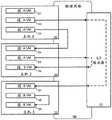
图1示出了通过网络虚拟化基础设施实现的逻辑网络100,其中在不同段或子网上的虚拟机(VM)通过共享路由器110进行通信。如所示出的,VM 121-129在主机机器131-133上运行,这些主机机器是通过物理网络105通信地链接的物理机器。FIG. 1 shows a
VM在网络的不同段中。具体而言,VM 121-125在网络的段A中,VM 126-129在网络的段B中。在网络的相同段中的VM能够利用链路层(L2)协议彼此通信,而在网络的不同段中的VM不能利用链路层协议彼此通信,并且必须通过网络层(L3)路由器或网关彼此通信。在不同主机机器中操作的VM通过物理网络105中的网络流量彼此通信,无论它们是否处于相同的网络段中。VMs are in different segments of the network. Specifically, VMs 121-125 are in segment A of the network and VMs 126-129 are in segment B of the network. VMs in the same segment of the network are able to communicate with each other using link layer (L2) protocols, while VMs in different segments of the network cannot communicate with each other using link layer protocols and must go through network layer (L3) routers or gateways to each other communication. VMs operating in different host machines communicate with each other through network traffic in the
主机机器131-133正在运行实现软件交换机的管理程序,其允许在同一主机机器内的相同段中的VM彼此本地通信而无需经过物理网络105。但是,属于不同段的VM必须经过只有在物理网络的后面才能到达的L3路由器,诸如共享路由器110。即使在相同主机机器中操作的VM之间也是这种情况。例如,VM 125和VM 126之间的流量必须经过物理网络105和共享路由器110,即使它们两者都在主机机器132上操作。The host machines 131 - 133 are running a hypervisor that implements a software switch that allows VMs in the same segment within the same host machine to communicate with each other locally without going through the
所需要的是用于在VM可以运行的每个主机处转发L3分组的分布式路由器。该分布式路由器应该使得能够在本地(即,在起始管理程序处)转发数据分组,使得在源VM和目的地VM之间恰好只有一跳。What is needed is a distributed router for forwarding L3 packets at each host where the VM can run. The distributed router should enable data packets to be forwarded locally (ie, at the originating hypervisor) such that there is exactly one hop between the source VM and the destination VM.
发明内容SUMMARY OF THE INVENTION
为了便于在虚拟化网络环境中的主机机器上运行的逻辑网络的虚拟机(VM)之间的L3分组转发,一些实施例定义了用于逻辑网络的逻辑路由器或者逻辑路由元件(LRE)。在一些实施例中,LRE跨其逻辑网络的主机机器分布式地操作为虚拟分布式路由器(VDR),其中每个主机机器将其自己的LRE的本地实例操作为受管理的物理路由元件(MPRE),用于为在那个主机上运行的VM执行L3分组转发。在一些实施例中,MPRE允许在同一主机机器上运行的VM之间的分组的L3转发在主机机器处本地执行,而不必经过物理网络。一些实施例定义了用于不同租户的不同LRE,并且主机机器可以将不同的LRE操作为多个MPRE。在一些实施例中,在同一主机机器上运行的用于不同租户的不同MPRE在受管理的物理交换元件(MPSE)上共享同一端口和同一L2 MAC地址。To facilitate L3 packet forwarding between virtual machines (VMs) of logical networks running on host machines in a virtualized network environment, some embodiments define logical routers or logical routing elements (LREs) for logical networks. In some embodiments, an LRE operates as a virtual distributed router (VDR) distributed across the host machines of its logical network, with each host machine operating its own local instance of the LRE as a managed physical routing element (MPRE) ) to perform L3 packet forwarding for VMs running on that host. In some embodiments, MPRE allows L3 forwarding of packets between VMs running on the same host machine to be performed locally at the host machine without having to go through a physical network. Some embodiments define different LREs for different tenants, and the host machine may operate the different LREs as multiple MPREs. In some embodiments, different MPREs for different tenants running on the same host machine share the same port and the same L2 MAC address on the Managed Physical Switch Element (MPSE).
在一些实施例中,LRE包括一个或多个逻辑接口(LIF),每个逻辑接口用作到网络的特定段的接口。在一些实施例中,每个LIF可以通过其自己的IP地址寻址并且用作其网络的特定段的网络节点(例如,VM)的缺省网关或ARP代理。每个网络段具有其自己的到LRE的逻辑接口,并且每个LRE具有其自己的一组逻辑接口。每个逻辑接口具有在网络虚拟化基础设施内唯一的、其自己的标识符(例如,IP地址或覆盖网络标识符)。In some embodiments, the LRE includes one or more logical interfaces (LIFs), each logical interface serving as an interface to a particular segment of the network. In some embodiments, each LIF is addressable by its own IP address and serves as the default gateway or ARP proxy for network nodes (eg, VMs) for a particular segment of its network. Each network segment has its own logical interface to the LRE, and each LRE has its own set of logical interfaces. Each logical interface has its own identifier (eg, IP address or overlay network identifier) that is unique within the network virtualization infrastructure.
在一些实施例中,采用此类逻辑路由器的逻辑网络通过使在不同主机机器中操作的MPRE对所有虚拟机看起来是相同的来进一步增强网络虚拟化。在这些实施例中的一些实施例中,可通过对于系统中所有LRE相同的虚拟MAC地址(VMAC)在L2数据链路层处对每个LRE寻址。每个主机机器与唯一的物理MAC地址(PMAC)相关联。可由其它主机机器通过物理网络利用其主机机器的唯一PMAC来对实现特定LRE的每个MPRE唯一寻址。在一些实施例中,离开MPRE的每个分组具有VMAC作为源地址,并且在分组进入PNIC和离开主机到物理网络之前,主机机器将把源地址改变为唯一PMAC。在一些实施例中,进入MPRE的每个分组具有VMAC作为目的地地址,并且如果目的地地址是与主机相关联的唯一PMAC地址,则主机将把目的地MAC地址改变为通用VMAC。在一些实施例中,网络段的LIF用作用于在该网络段中的VM的缺省网关。接收对其LIF中的一个的ARP查询的MPRE在本地响应查询,而无需将查询转发到其它主机机器。In some embodiments, logical networks employing such logical routers further enhance network virtualization by making MPREs operating in different host machines appear the same to all virtual machines. In some of these embodiments, each LRE may be addressed at the L2 data link layer by the same virtual MAC address (VMAC) for all LREs in the system. Each host machine is associated with a unique physical MAC address (PMAC). Each MPRE implementing a particular LRE can be uniquely addressed by other host machines over the physical network using their host machine's unique PMAC. In some embodiments, each packet leaving the MPRE has a VMAC as the source address, and the host machine will change the source address to a unique PMAC before the packet enters the PNIC and leaves the host to the physical network. In some embodiments, each packet entering the MPRE has a VMAC as the destination address, and if the destination address is the unique PMAC address associated with the host, the host will change the destination MAC address to a generic VMAC. In some embodiments, the LIF of a network segment is used as the default gateway for VMs in that network segment. An MPRE that receives an ARP query for one of its LIFs responds to the query locally without forwarding the query to other host machines.
为了为不运行虚拟化软件或操作MPRE的物理主机机器执行L3层路由,一些实施例指定运行在主机机器上的MPRE来充当用于这些非-VDR主机机器中的每一个的专用路由代理(指定的实例或指定的MPRE)。在一些实施例中,从虚拟机到物理主机的数据流量通过各个MPRE进行,而从物理主机到虚拟机的数据流量必须经过指定的MPRE。To perform L3 layer routing for physical host machines that do not run virtualization software or operate MPRE, some embodiments designate MPRE running on the host machine to act as a dedicated routing agent for each of these non-VDR host machines (specifying instance or the specified MPRE). In some embodiments, data traffic from virtual machines to physical hosts goes through individual MPREs, while data traffic from physical hosts to virtual machines must pass through designated MPREs.
在一些实施例中,在主机机器中的至少一个MPRE被配置为桥接MPRE,并且这种桥包括被配置为用于桥接而不是用于路由的逻辑接口。配置为用于路由的逻辑接口(路由LIF)通过将L3层网络地址解析为L2 MAC地址而在逻辑网络的不同段之间执行L3层路由。配置为用于桥接的逻辑接口(桥接LIF)通过将MAC地址与网络段标识符(例如,VNI)或逻辑接口绑定来执行桥接。In some embodiments, at least one MPRE in the host machine is configured as a bridge MPRE, and such bridge includes a logical interface configured for bridging rather than routing. A logical interface (routing LIF) configured for routing performs L3 layer routing between different segments of a logical network by resolving L3 layer network addresses to L2 MAC addresses. A logical interface configured for bridging (bridging LIF) performs bridging by binding a MAC address to a network segment identifier (eg, VNI) or logical interface.
在一些实施例中,在如上所述的主机机器中操作的LRE通过由控制器集群生成的配置数据集进行配置。在一些实施例中,控制器又基于被不同租户或用户创建和指定的逻辑网络生成这些配置数据集。在一些实施例中,用于网络虚拟化基础设施的网络管理器允许用户生成可以通过网络虚拟化基础设施实现的不同的逻辑网络,并且然后将这些逻辑网络的参数推送到控制器,以便控制器能够生成特定于主机机器的配置数据集,包括用于LRE的配置数据。在一些实施例中,网络管理器向主机机器提供用于提取用于LRE的配置数据的指令。In some embodiments, an LRE operating in a host machine as described above is configured through a configuration data set generated by a cluster of controllers. In some embodiments, the controller in turn generates these configuration data sets based on logical networks created and specified by different tenants or users. In some embodiments, a network manager for a network virtualization infrastructure allows a user to generate different logical networks that can be implemented by the network virtualization infrastructure, and then push the parameters of these logical networks to the controller so that the controller can Ability to generate host machine-specific configuration data sets, including configuration data for LREs. In some embodiments, the network manager provides instructions to the host machine for extracting configuration data for the LRE.
一些实施例动态地收集和交付用于LRE的路由信息。在一些实施例中,边缘VM从其它路由器获知网络路由并且将获知的路由发送到控制器集群,控制器集群又将获知的路由传播到在主机机器中操作的LRE。Some embodiments dynamically collect and deliver routing information for LREs. In some embodiments, edge VMs learn network routes from other routers and send the learned routes to the controller cluster, which in turn propagates the learned routes to LREs operating in the host machine.
前面的发明内容旨在用作对本发明的一些实施例的简要介绍。它并不意味着是本文档中所公开的所有发明性主题的介绍或概述。以下的具体实施方式和在具体实施方式中参考的附图说明将进一步描述在发明内容以及其它实施例中所描述的实施例。因此,为了理解本文档所描述的所有实施例,需要对发明内容、具体实施方式和附图说明进行全面地阅读。此外,所要求保护的主题不受在发明内容、具体实施方式和附图说明中的说明性细节的限制,而是要由所附权利要求来限定,这是因为所要求保护的主题可以在不背离本主题的精神的情况下以其它特定的形式来体现。The foregoing summary is intended to serve as a brief introduction to some embodiments of the present invention. It is not intended to be an introduction or overview of all inventive subject matter disclosed in this document. The following detailed description and the accompanying drawings referenced in the detailed description further describe the embodiments described in this summary and other examples. Therefore, in order to understand all of the embodiments described in this document, a thorough reading of the Summary, Detailed Description, and Description of the Drawings is required. Furthermore, the claimed subject matter is not to be limited by the illustrative details in the Summary, Detailed Description, and Brief Description of the Drawings, but rather by the appended claims, since the claimed subject matter may be be embodied in other specific forms that depart from the spirit of the subject matter.
附图说明Description of drawings
本发明的新颖特征在所附权利要求中阐述。但是,出于解释的目的,本发明的若干种实施例在以下图中阐述。The novel features of the invention are set forth in the appended claims. However, for purposes of explanation, several embodiments of the invention are set forth in the following figures.
图1示出了通过网络虚拟化基础设施实现的逻辑网络,其中在不同段或子网上的虚拟机(VM)通过共享路由器进行通信。Figure 1 shows a logical network implemented through a network virtualization infrastructure, where virtual machines (VMs) on different segments or subnets communicate through shared routers.
图2示出了由在主机机器中本地操作为MPRE的LRE执行的分组转发操作。Figure 2 illustrates packet forwarding operations performed by an LRE operating locally as an MPRE in the host machine.
图3示出了运行操作用于LRE的MPRE的虚拟化软件的主机机器。Figure 3 shows a host machine running virtualization software operating MPRE for LRE.
图4示出了通过MPSE进行的L2转发操作。Figure 4 shows the L2 forwarding operation by MPSE.
图5a-b示出了通过MPRE结合MPSE的L3路由操作。Figures 5a-b illustrate L3 routing operations through MPRE in conjunction with MPSE.
图6a-b示出了通过MPRE为来自主机之外的分组执行的L3路由操作。Figures 6a-b illustrate L3 routing operations performed by MPRE for packets from outside the host.
图7概念性地示出了具有由跨不同主机机器的MPRE实现的LRE的逻辑网络。Figure 7 conceptually illustrates a logical network with LREs implemented by MPREs across different host machines.
图8示出了在网络虚拟化基础设施的主机机器中的MPRE的物理实现。Figure 8 shows the physical implementation of MPRE in a host machine of a network virtualization infrastructure.
图9示出了来自不同段的虚拟机的数据分组如何被定向到主机内的不同逻辑接口。Figure 9 shows how data packets from virtual machines of different segments are directed to different logical interfaces within the host.
图10示出了在主机机器中操作的示例MPRE的框图。Figure 10 shows a block diagram of an example MPRE operating in a host machine.
图11概念性地示出了当处理来自MPSE的数据分组时由MPRE执行的过程。Figure 11 conceptually illustrates the process performed by the MPRE when processing data packets from the MPSE.
图12示出了用于一些实施例的、具有可通过共用VMAC和唯一PMAC寻址的MPRE的逻辑网络。Figure 12 illustrates a logical network with MPREs addressable by a common VMAC and unique PMAC for some embodiments.
图13示出了使用共用VMAC和唯一PMAC的示例路由的L3网络流量。Figure 13 shows example routed L3 network traffic using a common VMAC and unique PMAC.
图14概念性地示出了用于通过上行链路模块执行的预处理操作的过程。Figure 14 conceptually illustrates a process for preprocessing operations performed by the uplink module.
图15概念性地示出了用于通过上行链路模块执行的后处理操作的过程。15 conceptually illustrates a process for post-processing operations performed by the uplink module.
图16示出了用于在逻辑网络中的LRE的逻辑接口的ARP查询操作。Figure 16 shows an ARP query operation for a logical interface of an LRE in a logical network.
图17示出了用于一些实施例的、MPRE发起的ARP查询。Figure 17 illustrates an MPRE-initiated ARP query for some embodiments.
图18示出了MPRE充当用于响应该MPRE能够解析的ARP询问的代理。Figure 18 shows an MPRE acting as a proxy for responding to ARP queries that the MPRE is able to resolve.
图19示出了在用于与发送者MPRE处于相同主机机器内的虚拟机的ARP询问中使用唯一PMAC。Figure 19 illustrates the use of a unique PMAC in an ARP query for a virtual machine within the same host machine as the sender MPRE.
图20和21示出了在MPRE已更新其解析表之后在不同段的VM之间的消息传递操作。Figures 20 and 21 illustrate message passing operations between VMs of different segments after MPRE has updated its resolution table.
图22概念性地示出了用于通过利用MPRE为到来数据分组处理地址解析的过程。Figure 22 conceptually illustrates a process for handling address resolution for incoming data packets by utilizing MPRE.
图23示出了指定用于处理去向和来自物理主机的分组的L3路由的MPRE的逻辑网络。Figure 23 shows a logical network of MPREs designated for handling L3 routing of packets to and from physical hosts.
图24示出了由逻辑网络中的非-VDR物理主机发起的ARP操作。Figure 24 shows an ARP operation initiated by a non-VDR physical host in a logical network.
图25示出了使用指定的MPRE用于将来自不同主机上的虚拟机的分组路由到物理主机。Figure 25 illustrates the use of designated MPREs for routing packets from virtual machines on different hosts to physical hosts.
图26a-b示出了使用指定的MPRE用于将来自物理主机的分组路由到不同主机上的虚拟机。Figures 26a-b illustrate the use of designated MPREs for routing packets from physical hosts to virtual machines on different hosts.
图27概念性地示出了用于处理来自非-VDR物理主机的L3层流量的过程。Figure 27 conceptually illustrates a process for handling L3 layer traffic from a non-VDR physical host.
图28概念性地示出了用于处理到非-VDR物理主机的L3层流量的过程2800。Figure 28 conceptually illustrates a
图29示出了包括用于用作不同覆盖网络之间的桥的桥LIF的LRE。Figure 29 shows an LRE including a bridge LIF for use as a bridge between different overlay networks.
图30示出了包括多个主机机器的逻辑网络,其中至少一个主机机器是包括具有配置为桥LIF的逻辑接口的MPRE的主机机器。30 shows a logical network including multiple host machines, where at least one of the host machines is a host machine including an MPRE with a logical interface configured as a bridge LIF.
图31示出了通过MPRE获知MAC地址。Figure 31 shows the learning of the MAC address by MPRE.
图32示出了利用由MPRE先前获知的MAC-VNI配对在两个不同的覆盖网络上的两个VM之间的桥接。Figure 32 illustrates bridging between two VMs on two different overlay networks using MAC-VNI pairing previously known by MPRE.
图33示出了在两个VM之间的桥接,这两个VM不在与桥接MPRE相同的主机中操作。Figure 33 shows bridging between two VMs that are not operating in the same host as the bridging MPRE.
图34a示出了其中目的地MAC地址在桥接表中没有匹配的条目并且MPRE必须泛洪网络以寻找配对的桥接操作。Figure 34a shows a bridging operation where the destination MAC address has no matching entry in the bridging table and the MPRE must flood the network to find a pairing.
图34b示出了从对泛红的响应中获知MAC地址配对。Figure 34b shows learning of MAC address pairings from responses to redness.
图35概念性地示出了用于在MPRE处执行桥接的过程。Figure 35 conceptually illustrates a process for performing bridging at an MPRE.
图36示出了网络虚拟化基础设施,其中逻辑网络规范被转换为用于主机机器中的LRE的配置。Figure 36 shows a network virtualization infrastructure where logical network specifications are translated into configurations for LREs in host machines.
图37概念性地示出了从网络管理器向在各个主机机器中操作的LRE交付配置数据。Figure 37 conceptually illustrates delivery of configuration data from a network manager to LREs operating in various host machines.
图38示出了被交付给各个主机机器的配置数据集的结构。Figure 38 shows the structure of the configuration data set delivered to each host machine.
图39示出了收集和交付动态路由信息到LRE的MPRE。Figure 39 shows the MPRE collecting and delivering dynamic routing information to the LRE.
图40概念性地示出了本发明的一些实施例利用其来实现的电子系统。Figure 40 conceptually illustrates an electronic system with which some embodiments of the present invention are implemented.
具体实施方式Detailed ways
在以下描述中,出于解释的目的阐述了许多细节。但是,本领域普通技术人员将认识到,本发明可以在不使用这些具体细节的情况下进行实践。在其它的情况下,众所周知的结构和设备以框图的形式示出,以便防止用不必要的细节模糊本发明的描述。In the following description, numerous details are set forth for the purpose of explanation. However, one of ordinary skill in the art will recognize that the present invention may be practiced without the use of these specific details. In other instances, well-known structures and devices are shown in block diagram form in order to avoid obscuring the description of the present invention with unnecessary detail.
为了便于在虚拟化网络环境中的主机机器上运行的逻辑网络的虚拟机(VM)之间进行L3分组转发,一些实施例定义了用于逻辑网络的逻辑路由器或者逻辑路由元件(LRE)。在一些实施例中,LRE跨其逻辑网络的主机机器分布式地操作为虚拟分布式路由器(VDR),其中每个主机机器将其自己的LRE的本地实例操作为受管理的物理路由元件(MPRE),用于为在那个主机上运行的VM执行L3分组转发。在一些实施例中,MPRE允许在同一主机机器上运行的VM之间的分组的L3转发在主机机器处本地执行,而不必经过物理网络。一些实施例定义了用于不同租户的不同的LRE,并且主机机器可以将不同的LRE操作为多个MPRE。在一些实施例中,在同一主机机器上运行的用于不同租户的不同MPRE在受管理的物理交换元件(MPSE)上共享同一端口和同一L2 MAC地址。To facilitate L3 packet forwarding between virtual machines (VMs) of logical networks running on host machines in a virtualized network environment, some embodiments define logical routers or logical routing elements (LREs) for logical networks. In some embodiments, an LRE operates as a virtual distributed router (VDR) distributed across the host machines of its logical network, with each host machine operating its own local instance of the LRE as a managed physical routing element (MPRE) ) to perform L3 packet forwarding for VMs running on that host. In some embodiments, MPRE allows L3 forwarding of packets between VMs running on the same host machine to be performed locally at the host machine without having to go through a physical network. Some embodiments define different LREs for different tenants, and the host machine may operate the different LREs as multiple MPREs. In some embodiments, different MPREs for different tenants running on the same host machine share the same port and the same L2 MAC address on the Managed Physical Switch Element (MPSE).
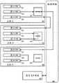
对于一些实施例,图2示出了由在主机机器中本地操作为MPRE的LRE执行的分组转发操作。每个主机机器执行虚拟化功能,以便托管一个或多个VM并且执行交换功能,使得VM可以在网络虚拟化基础设施中互相通信。每个MPRE在其主机机器内本地执行L3路由操作,使得即使当同一主机机器上的两个VM属于不同的网络段时,这两个VM之间的流量也将始终在本地进行。For some embodiments, Figure 2 illustrates packet forwarding operations performed by an LRE operating locally as an MPRE in a host machine. Each host machine performs virtualization functions to host one or more VMs and performs switching functions so that the VMs can communicate with each other in a network virtualization infrastructure. Each MPRE performs L3 routing operations locally within its host machine, so that even when two VMs on the same host machine belong to different network segments, traffic between these two VMs will always be local.
图2示出了用于在VM 221-229之间的网络通信的逻辑网络200的实现。逻辑网络200是在通过物理网络205互连的一组计算和存储资源上被虚拟化的网络。互连的这组计算和存储资源以及物理网络形成网络虚拟化基础设施。VM 221-229被主机机器231-233托管,这些主机机器通过物理网络205通信地链接。在一些实施例中,每个主机机器231-233是由能够创建和托管VM的操作系统(例如,Linux)管理的计算设备。VM 221-229是每个都被分配一组网络地址(例如,用于L2的MAC地址、用于L3的IP地址等)并且可以向诸如其它VM的其它网络元件发送和从其接收网络数据的虚拟机。Figure 2 shows an implementation of a
VM由在主机机器231-233上运行的虚拟化软件(未示出)来管理。虚拟化软件可以包括一个或多个软件组件和/或层,可能地包括在虚拟机技术领域中被称为“虚拟机监视器”、“管理程序”或虚拟化内核的软件组件中的一个或多个软件组件。由于虚拟化术语随着时间的推移在演化并且还没有完全被标准化,因此这些术语并不总能在其所指代的软件层和组件之间提供明确的区分。如本文所使用的,术语“虚拟化软件”旨在一般地指逻辑上介于虚拟机和主机平台之间的软件层或组件。VMs are managed by virtualization software (not shown) running on host machines 231-233. Virtualization software may include one or more software components and/or layers, possibly including one or more of the software components known in the art of virtual machine technology as a "hypervisor," a "hypervisor," or a virtualization kernel. Multiple software components. Because virtualization terms have evolved over time and have not been fully standardized, these terms do not always provide a clear distinction between the software layers and components they refer to. As used herein, the term "virtualization software" is intended to generally refer to a layer or component of software logically interposed between a virtual machine and a host platform.
在图2的例子中,每个VM在逻辑网络200的两个段中的其中一个段中操作。VM 221-225在段A中操作,而VM 226-229在段B中操作。在一些实施例中,网络段是其中网络元件通过链路层L2协议彼此通信的网络的一部分,诸如IP子网。在一些实施例中,网络段是封装覆盖网络,诸如VXLAN或VLAN。In the example of FIG. 2 , each VM operates in one of two segments of
在一些实施例中,在网络的相同段中的VM能够利用链路层(L2)协议(例如,根据每个VM的L2 MAC地址)彼此通信,而网络的不同段中的VM不能利用链路层协议彼此通信并且必须通过网络层(L3)路由器或网关彼此通信。在一些实施例中,VM之间的L2层流量由在每个主机机器内本地操作的MPSE(未示出)处理。因此,例如,从VM 223到VM 224的网络流量将经过在主机231中操作的第一MPSE,第一MPSE从其端口中的一个端口接收数据并且通过物理网络205将数据发送到在主机机器232中操作的第二MPSE,第二MPSE然后将通过其端口中的一个端口将数据发送到VM 224。同样,从VM 228到VM 229的同一段的网络流量将经过在主机233中操作的单个MPSE,该MPSE在主机233内本地地将流量从一个虚拟端口转发到另一个虚拟端口。In some embodiments, VMs in the same segment of the network are able to communicate with each other using link layer (L2) protocols (eg, based on each VM's L2 MAC address), while VMs in different segments of the network cannot utilize the link Layer protocols communicate with each other and must communicate with each other through network layer (L3) routers or gateways. In some embodiments, L2 layer traffic between VMs is handled by MPSE (not shown) operating locally within each host machine. Thus, for example, network traffic from
与其实现依赖于用于处理不同网络段之间的流量的外部L3路由器(其可以被实现为标准的物理路由器、专门用于执行路由功能的VM,等等)的图1的逻辑网络100不同,图2的逻辑网络200的实现分别使用MPRE 241-243在主机机器231-233内本地执行L3路由功能。在不同主机机器中的MPRE为逻辑网络200中的VM联合执行逻辑L3路由器的功能。在一些实施例中,LRE被实现为跨不同的主机机器被复制或实例化以成为其MPRE的数据结构。在图2的例子中,LRE在主机机器231-233中被实例化为MPRE 241-243。Rather than implementing the
在图2的例子中,源自VM 222并且去往VM 227的网络流量的L3路由通过MPRE 241来处理,其中MPRE 241是在托管VM 222的主机机器231上本地运行的LRE具体实例(instantiation)。在将路由的数据分组通过物理网络205发送到VM 227之前,MPRE 241在主机机器231内本地执行L3层路由操作(例如,链路层地址解析)。这是在没有外部的共享L3路由器的情况下完成的。同样,源自VM 225并且去往VM 226的网络流量的L3路由通过MPRE242来处理,MPRE 242是在托管VM 225的主机机器232上本地运行的LRE具体实例。MPRE 242在主机232内本地执行L3层路由操作并且将路由的数据分组直接发送到也被主机机器232托管的VM 226。因此,在这两个VM 225和226之间的流量不需要通过物理网络205或外部路由器来发送。In the example of FIG. 2, L3 routing of network traffic originating from
下面描述若干个本发明更详细的实施例。部分I描述了VDR和实现基于LRE的MPRE的主机的体系架构。部分II描述了用于分组处理的VDR的各种用途。部分III描述了VDR的控制和配置。最后,部分IV描述了本发明的一些实施例利用其来实现的电子系统。Several more detailed embodiments of the invention are described below. Part I describes the architecture of a VDR and a host implementing an LRE-based MPRE. Section II describes various uses of VDR for packet processing. Section III describes the control and configuration of the VDR. Finally, Section IV describes electronic systems with which some embodiments of the present invention are implemented.
I.VDR的体系架构I. Architecture of VDR
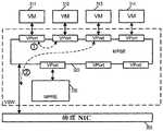
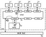
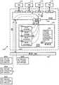
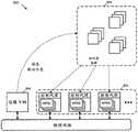
在一些实施例中,LRE在运行在托管一个或多个VM(例如,在多租户数据中心内)的主机机器上的虚拟化软件(例如,管理程序、虚拟机监视器,等等)内操作。虚拟化软件管理VM的操作以及它们对主机机器的物理资源和网络资源的访问,并且LRE的本地具体实例在主机机器中操作为其本地的MPRE。对于一些实施例,图3示出了运行包括LRE的MPRE的虚拟化软件305的主机机器300。主机机器通过物理网络390连接到,例如,其它类似的主机机器。在一些实施例中,物理网络390可以包括各种物理交换机和路由器。In some embodiments, the LRE operates within virtualization software (eg, hypervisor, hypervisor, etc.) running on a host machine hosting one or more VMs (eg, within a multi-tenant data center) . The virtualization software manages the operation of the VMs and their access to the host machine's physical and network resources, and the local concrete instance of the LRE operates as its local MPRE in the host machine. For some embodiments, FIG. 3 shows a
如所示出的,主机机器300可以通过物理NIC(PNIC)395对物理网络390访问。主机机器300还运行虚拟化软件305并且托管VM 311-314。虚拟化软件305用作托管的VM和物理NIC 395(以及其它物理资源,诸如处理器和存储器)之间的接口。每个VM包括用于通过虚拟化软件305访问网络的虚拟NIC(VNIC)。在VM中的每个VNIC负责在VM和虚拟化软件305之间交换分组。在一些实施例中,VNIC是由虚拟NIC仿真器实现的物理NIC的软件抽象。As shown,
虚拟化软件305管理VM 311-314的操作,并且包括用于管理VM对物理网络的访问(在一些实施例中,通过实现VM连接到的逻辑网络)的若干个组件。如所示出的,虚拟化软件包括若干个组件,包括MPSE 320、MPRE 330、控制器代理340、VTEP 350和一组上行链路管道370。The
控制器代理340从控制器或控制器集群接收控制平面消息。在一些实施例中,这些控制平面消息包括用于配置虚拟化软件的各种组件(诸如MPSE 320和MPRE 330)和/或虚拟机的配置数据。在图3所示的例子中,控制器代理340从物理网络390接收来自控制器集群360的控制平面消息并且又通过控制信道而无需经过MPSE 320将接收到的配置数据提供给MPRE 330。但是,在一些实施例中,控制器代理340从独立于物理网络390的直接数据通道(未示出)接收控制平面消息。在一些其它实施例中,控制器代理从MPSE 320接收控制平面消息并且通过MPSE 320将配置数据转发到路由器330。控制器代理和虚拟化软件的配置将在下面的部分III中进一步描述。The
VTEP(VXLAN隧道端点)350允许主机300用作用于逻辑网络流量(例如,VXLAN流量)的隧道端点。VXLAN是覆盖网络封装协议。由VXLAN封装创建的覆盖网络有时被称为VXLAN网络,或者简单地称为VXLAN。当主机300上的VM将数据分组(例如以太网帧)发送到在同一VXLAN网络中但是在不同主机上的另一个VM时,VTEP在把分组发送到物理网络之前,将利用VXLAN网络的VNI和该VTEP的网络地址封装数据分组。分组隧道穿过物理网络(即,封装使得底层分组对中间网络元件透明)到目的地主机。在目的地主机处的VTEP解封装分组并且只将原始内部数据分组转发到目的地VM。在一些实施例中,VTEP模块只用作用于VXLAN封装的控制器接口,而VXLAN分组的封装和解封装在上行链路模块370处完成。VTEP (VXLAN Tunnel Endpoint) 350 allows
MPSE 320将网络数据交付给物理NIC 395和接收来自物理NIC 395的网络数据,物理NIC 395与物理网络390接口。MPSE还包括将物理NIC与VM 311-314、MPRE 330和控制器代理340通信地互连的多个虚拟端口(vPort)。在一些实施例中,每个虚拟端口与唯一的L2MAC地址相关联。MPSE在连接到其虚拟端口的任何两个网络元件之间执行L2链路层分组转发。MPSE还在连接到其虚拟端口中的任何一个端口的任何网络元件与物理网络390上的可到达的L2网络元件(例如,运行在另一个主机上的另一个VM)之间执行L2链路层分组转发。在一些实施例中,MPSE实现跨不同主机机器操作并且可以在同一主机机器上或不同主机机器上的VM之间执行L2分组交换的逻辑交换元件(LSE)的本地具体实例,或者实现用于若干个逻辑网络的若干个这种LSE。
MPRE 330对从MPSE 320的虚拟端口接收到的数据分组执行L3路由(例如,通过执行L3 IP地址到L2 MAC地址的解析)。每个路由的数据分组然后被发送回到MPSE 320,以根据解析的L2 MAC地址被转发到其目的地。这个目的地可以是连接到MPSE 320上的虚拟端口的另一个VM,或者物理网络390上的可到达的L2网络元件(例如,在另一个主机上运行的另一个VM、物理的非虚拟化的机器,等等)。
如所提到的,在一些实施例中,MPRE是跨不同主机机器操作并且可以在同一主机机器上或在不同主机机器上的VM之间执行L3分组转发的逻辑路由元件(LRE)的本地具体实例。在一些实施例中,主机机器可以具有连接到单个MPSE的多个MPRE,其中在主机机器中的每个MPRE实现不同的LRE。MPRE和MPSE被称为“物理”路由/交换元件,以便与“逻辑”路由/交换元件进行区分,即使MPRE和MPSE在一些实施例中用软件实现。在一些实施例中,MPRE被称为“软件路由器”并且MPSE被称为“软件交换机”。在一些实施例中,LRE和LSE被统称为逻辑转发元件(LFE),而MPRE和MPSE被统称为受管理的物理转发元件(MPFE)。As mentioned, in some embodiments an MPRE is a local implementation of a Logical Routing Element (LRE) that operates across different host machines and can perform L3 packet forwarding on the same host machine or between VMs on different host machines instance. In some embodiments, a host machine may have multiple MPREs connected to a single MPSE, where each MPRE in the host machine implements a different LRE. MPREs and MPSEs are referred to as "physical" routing/switching elements to distinguish them from "logical" routing/switching elements, even though MPREs and MPSEs are implemented in software in some embodiments. In some embodiments, MPREs are called "software routers" and MPSEs are called "software switches." In some embodiments, LREs and LSEs are collectively referred to as logical forwarding elements (LFEs), while MPREs and MPSEs are collectively referred to as managed physical forwarding elements (MPFEs).
在一些实施例中,MPRE 330包括一个或多个逻辑接口(LIF),每个逻辑接口用作与网络的特定段的接口。在一些实施例中,每个LIF可通过其自己的IP地址寻址并且用作用于其网络特定段的网络节点(例如,VM)的缺省网关或ARP代理。如下面详细描述的,在一些实施例中,在不同主机机器中的所有MPRE都可通过相同的“虚拟”MAC地址寻址,而每个MPRE也被分配“物理”MAC地址,以便指示MPRE在哪个主机机器中操作。In some embodiments,
上行链路模块370在MPSE 320和物理NIC 395之间中继数据。上行链路模块370包括出口链和入口链,其中每一个都执行多个操作。这些操作中的一些是用于MPRE 330的预处理和/或后处理操作。上行链路模块370的操作将在下面通过参考图14-15进一步描述。
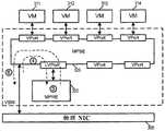
如由图3所示,虚拟化软件305具有来自多个不同LRE的多个MPRE。在多租户环境中,主机机器可以操作来自多个不同用户或租户的虚拟机(即,连接到不同的逻辑网络)。在一些实施例中,每个用户或租户在主机中具有用于处理其L3路由的相应的MPRE具体实例。在一些实施例中,虽然不同的MPRE属于不同的租户,但是它们都共享MPSE 320上的同一vPort,并且因此共享同一L2 MAC地址。在一些其它实施例中,属于不同租户的每个不同的MPRE具有其自己到MPSE的端口。As shown by FIG. 3,
MPSE 320和MPRE 330使得数据分组有可能在VM 311-314之中转发,而无需通过外部物理网络390发送(只要VM连接到同一逻辑网络,因为不同租户的VM将彼此隔离)。
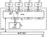
图4示出了通过MPSE 320的L2转发操作。标记为“1”的操作表示VM 311到VM 312之间的网络流量,其完全在主机机器300内发生。这与标记为“2”的操作形成对比,其中标记为“2”的操作表示在VM 313和另一个主机机器上的另一个VM之间的网络流量。为了到达另一个主机机器,MPSE 320通过NIC 395将分组发送到物理网络390。FIG. 4 shows the L2 forwarding operation by
图5a-b示出了通过与MPSE 320结合MPRE 330进行的L3路由操作。MPRE 330具有相关联的MAC地址并且可以从VM 311-314中的任何一个接收L2层流量。图5a示出了用于其目的地与MPRE 330在同一主机中的分组的第一L3路由操作。在标记为“1”的操作中,VM 312通过利用MPRE的MAC地址将数据分组发送到MPRE 330。在标记为“2”的操作中,MPRE 330通过将接收到的数据分组的目的地L3层IP地址解析为L2层目的地MAC地址对该数据分组执行L3路由操作。如下面详细描述的,这可能需要MPRE 330发送地址解析协议(ARP)请求。路由的分组然后在标记为“3”的操作中发送回到MPSE 320。由于目的地MAC地址用于主机机器300内的VM(即,VM 311),因此MPSE 320在操作“3”中将路由的分组直接转发到目的地VM,而无需分组曾经到达物理网络390。Figures 5a-b illustrate L3 routing operations by
图5b示出了用于其目的地在只能通过物理网络到达的远程主机内的分组的第二L3路由操作。操作“4”和“5”与“1”和“2”的操作类似,在此期间,VM 312发送数据分组到MPRE330并且MPRE 330对接收到的数据分组执行(一个或多个)L3路由操作并且将路由的分组发送回到MPSE 320(再一次,有可能发送ARP请求来将目的地IP地址解析为MAC地址)。在操作“6”期间,MPSE 320基于目的地的L2 MAC地址通过物理NIC 395将路由的分组发送出到物理网络。Figure 5b shows a second L3 routing operation for packets whose destination is within a remote host that can only be reached through the physical network. Operations "4" and "5" are similar to those of "1" and "2", during which
图5a-b示出了用于在与MPRE同一主机机器中的VM的L3路由操作。在一些实施例中,也可以使用MPRE来为MPRE的主机机器之外的实体执行L3路由操作。例如,在一些实施例中,主机机器的MPRE可以用作用于为不具有其自己的MPRE的另一个主机机器执行L3路由的“指定的实例”。用作“指定的实例”的MPRE的例子将在下面部分II.C中进一步描述。Figures 5a-b illustrate L3 routing operations for a VM in the same host machine as the MPRE. In some embodiments, MPRE may also be used to perform L3 routing operations for entities other than the MPRE's host machine. For example, in some embodiments, a host machine's MPRE may serve as a "designated instance" for performing L3 routing for another host machine that does not have its own MPRE. Examples of MPREs used as "specified instances" are described further below in Section II.C.
图6a-b示出了由MPRE 330为从物理网络390进入主机300的分组执行的L3路由操作。虽然从还操作其自己的MPRE的主机上的VM发送的分组将被该MPRE路由,但是分组也可以从本身不操作VDR MPRE的其它主机机器发送到VM 311-314。图6a示出了用于从物理网络接收到的并且在操作“1”至“3”中发送到主机300内的虚拟机的分组的路由操作。在操作“1”中,外部实体通过寻址MPRE的MAC地址通过到MPSE 320的物理网络将分组发送到MPRE 330。在标记为“2”的操作中,MPRE 330通过将接收到的数据分组的目的地L3层IP地址解析为L2层目的地MAC地址对该数据分组执行L3路由操作。路由的分组然后在标记为“3”的操作中经由MPSE 320发送到目的地虚拟机。6a-b illustrate L3 routing operations performed by
图6b示出了在操作“4”至“6”中用于从外部实体发送到另一个外部实体(例如,在另一个主机机器中的虚拟机)的分组的路由操作。操作“4”和“5”是与“1”和“2”类似的操作,在此期间,MPRE 330从物理网络和MPSE 320接收分组,并且对接收到的数据分组执行L3路由操作。在操作“6”中,MPRE 330将数据分组发送回到MPSE 320,MPSE 320基于解析的MAC地址将分组发送到在另一个主机机器中的另一个虚拟机。如下面所述,当MPRE 330是用于与不操作LRE的外部主机通信的LRE的指定的具体实例时,这可能发生。Figure 6b shows routing operations in operations "4" to "6" for packets sent from an external entity to another external entity (eg, a virtual machine in another host machine). Operations "4" and "5" are similar operations to "1" and "2", during which
在一些实施例中,主机机器300是通过用于形成能够支持逻辑网络的网络虚拟化基础设施的物理网络互连的许多主机机器之一。这种网络虚拟化基础设施能够通过同时实现一个或多个用户指定的逻辑网络支持多个租户。这种逻辑网络可以包括用于在虚拟机之间执行L3层路由的一个或多个逻辑路由器。在一些实施例中,逻辑路由器通过跨多个主机机器实例化的MPRE共同实现。In some embodiments,
图7概念性地示出了具有由跨不同主机机器的MPRE实现的逻辑路由器的逻辑网络701和702。逻辑网络701和702在包括通过物理网络互连的若干个主机机器的网络虚拟化基础设施上同时被实现。如在该图中所示,第一逻辑网络701是用于租户X并且第二逻辑网络702是用于租户Y。每个租户的逻辑网络包括多个虚拟机。租户X的虚拟机被划分到段A、B、C和D中。租户Y的虚拟机被划分到段E、F、G和H中。在一些实施例中,在段中的虚拟机能够利用L2链路层协议通过逻辑交换机彼此通信。在一些实施例中,至少一些段是封装覆盖网络,诸如VXLAN网络。在一些实施例中,每个段形成不同的IP子网。Figure 7 conceptually illustrates
每个逻辑网络具有其自己的逻辑路由器。用于租户X的逻辑网络701具有LRE 711作为用于在段A、B、C和D之间路由的逻辑路由器。用于租户Y的逻辑网络702具有LRE 712作为用于在段E、F、G和H之间路由的逻辑路由器。每个逻辑路由器在网络虚拟化基础设施中通过跨不同主机机器实例化的MPRE来实现。在LRE 711中的一些MPRE具体实例与在LRE 712中的一些MPRE具体实例在同一主机机器中操作。Each logical network has its own logical router.
每个网络段具有其自己的到逻辑路由器的逻辑接口,并且每个逻辑路由器具有其自己的一组逻辑接口。如所示出的,逻辑路由器711具有分别用于段A、B、C和D的逻辑接口LIF A、LIF B、LIF C和LIF D,而逻辑路由器712具有分别用于段E、F、G和H的逻辑接口LIFE、LIF F、LIF G和LIF H。每个逻辑接口具有其自己的、在网络虚拟化基础设施中唯一的标识符(例如,IP地址或覆盖网络标识符)。因此,租户X的网络流量可以与租户Y的网络流量完全隔离。Each network segment has its own logical interface to a logical router, and each logical router has its own set of logical interfaces. As shown,
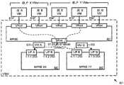
图8示出了在网络虚拟化基础设施的主机机器中的逻辑路由器的物理实现。具体而言,该图示出了在主机机器801和802中的逻辑网络701和702的(部分)实现。如所示出的,主机机器801正在托管虚拟机811-815,并且主机机器802正在托管虚拟机821-826。在这些虚拟机中,虚拟机811-812和821-823是租户X的虚拟机,而虚拟机813-816和824-826是租户Y的虚拟机。Figure 8 shows the physical implementation of a logical router in a host machine of a network virtualization infrastructure. Specifically, the figure shows a (partial) implementation of
每个主机机器包括用于两个不同租户的两个MPRE。主机机器801具有分别用于租户X和Y的MPRE 841和842。主机802具有分别用于租户X和Y的MPRE 843和844。主机801操作用于在虚拟机811-816和MPRE 841-842之间执行L2层分组转发的MPSE 851,而主机802正在操作用于在虚拟机821-826和MPRE 843-844之间执行L2层分组转发的MPSE 852。Each host machine includes two MPREs for two different tenants.
每个MPRE具有一组用于与在其主机机器上操作的虚拟机接口的逻辑接口。由于MPRE 841和843是用于租户X的MPRE,因此它们只能具有用于租户X的网络段(即,段A、B、C或D)的逻辑接口,而租户Y MPRE 842和844只能具有用于租户Y的网络段(即,段E、F、G和H)的逻辑接口。每个逻辑接口与网络IP地址相关联。附连到MPRE的逻辑接口的IP地址允许MPRE可通过运行在其本地主机上的VM寻址。例如,VM 811是在主机801上运行的段A虚拟机,其通过利用LIF A的IP地址,即,1.1.1.253,使用MPRE 841作为其L3路由器。在一些实施例中,MPRE可以包括被配置为不活动的LIF。例如,MPRE 841的LIF D处于活动状态,这是因为主机801不操作任何在段D中的VM。即,在一些实施例中,用于特定LRE的每个MPRE被配置有所有LRE的逻辑接口,但是,基于在具有本地LRE具体实例的主机机器上操作的VM,LRE的不同本地具体实例(即,MPRE)可能具有不同的LIF不活动。Each MPRE has a set of logical interfaces for interfacing with virtual machines operating on its host machine. Since
值得注意的是,在一些实施例中,即使用于相同段的LIF被附连到不同主机中的不同MPRE,这些LIF也具有相同的IP地址。例如,在主机801上的MPRE 842具有用于段E(LIF E)的逻辑接口,并且主机802上的MPRE 844也一样。MPRE 842的LIF E与MPRE 844的LIF E共享同一IP地址4.1.1.253。换句话说,VM 814(在主机801上运行的段E中的VM)和VM 824(在主机802上运行的段E中的VM)两者都使用同一IP地址4.1.1.253来访问其各自的MPRE。Notably, in some embodiments, LIFs for the same segment have the same IP address even though they are attached to different MPREs in different hosts. For example,
如所提到的,在一些实施例中,在同一主机机器上运行的不同MPRE共享MPSE上的同一端口,这意味着在同一主机上运行的所有MPRE共享L2 MAC地址。在一些实施例中,使用逻辑接口的唯一IP地址来分离来自不同租户和不同数据网络段的数据分组。在一些实施例中,使用其它识别机制将来自不同网络段的数据分组定向到不同的逻辑接口。一些实施例使用用于不同段的唯一标识符来分离来自不同段的分组。对于是子网的段,一些实施例使用分组中的IP地址来查看该分组是否来自正确的子网。对于对应于覆盖网络的段,一些实施例使用网络段标识符来将数据分组定向到其相应的逻辑接口。在一些实施例中,网络段标识符是作为逻辑网络的段的覆盖网络的标识符(例如,VNI、VXLAN ID或VLAN标签或ID)。在一些实施例中,与段的类型无关,逻辑网络的每个段被分配VNI作为该段的识别符。As mentioned, in some embodiments, different MPREs running on the same host machine share the same port on the MPSE, which means that all MPREs running on the same host share the L2 MAC address. In some embodiments, the unique IP addresses of the logical interfaces are used to separate data packets from different tenants and different data network segments. In some embodiments, other identification mechanisms are used to direct data packets from different network segments to different logical interfaces. Some embodiments use unique identifiers for different segments to separate packets from different segments. For segments that are subnets, some embodiments use the IP address in the packet to see if the packet is from the correct subnet. For segments corresponding to overlay networks, some embodiments use network segment identifiers to direct data packets to their corresponding logical interfaces. In some embodiments, the network segment identifier is an identifier (eg, a VNI, VXLAN ID, or VLAN tag or ID) of an overlay network that is a segment of a logical network. In some embodiments, regardless of the type of the segment, each segment of the logical network is assigned a VNI as the segment's identifier.
图9示出了来自不同段的虚拟机的数据分组如何被定向到主机801内的不同逻辑接口。如所示出的,VM 811-816被连接到MPSE 851的不同端口,而租户X的MPRE 841和租户Y的MPRE 842被连接到具有MAC地址“01:23:45:67:89:ab”的端口(对于本文的讨论,被称为“VMAC”)。来自段A VM 811的分组901和来自段G VM 815的分组902被发送到MPSE 851中。MPSE 851又基于用于分组901和902的目的地MAC地址“VMAC”将这两个分组定向到用于MPRE841和842的虚拟端口。分组901携带用于段A的VNI(“VNI A”),而分组902携带用于段G的VNI(“VNI G”)。MPRE 841的逻辑接口“LIF A”基于其网络段标识符“VNI A”接受分组901,而MPRE 842的逻辑接口“LIF G”基于其网络段标识符“VNI G”接受分组902。由于租户不共享相同的网络段,并因此不共享VNI,因此来自不同租户的数据分组被安全地彼此隔离。FIG. 9 shows how data packets from virtual machines of different segments are directed to different logical interfaces within
虽然这个图示出了使用分组上的VNI(网络标识符标签)来将分组分离到正确的逻辑路由器和逻辑路由器接口,但是不同的实施例可以使用其它鉴别机制。例如,一些实施例使用分组的源IP地址(以确保该分组是通过具有与源VM相同网络前缀的LIF发送的),或者源IP地址和网络标识符标签的组合。Although this figure shows the use of VNIs (Network Identifier Labels) on packets to separate packets to the correct logical router and logical router interface, different embodiments may use other authentication mechanisms. For example, some embodiments use the source IP address of the packet (to ensure that the packet was sent over a LIF with the same network prefix as the source VM), or a combination of the source IP address and the network identifier label.
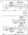
对于一些实施例,图10示出了在主机机器中操作的示例MPRE具体实例1000的框图。如所示出的,MPRE 1000在虚拟端口1053处被连接到MPSE 1050。MPSE 1050被连接到与MPRE 1000在同一主机中操作的虚拟机以及通过上行链路模块1070和物理NIC 1090连接到物理网络。MPRE 1000包括数据链路模块1010和路由处理器1005、逻辑接口数据储存装置1035、查找表储存装置1040、以及配置数据储存装置1045。路由处理器1005包括入口管道1020、出口管道1025、定序器1030。For some embodiments, Figure 10 shows a block diagram of an
数据链路模块1010是用于MPRE 1000与MPSE 1050的链路层(L2)接口。它接受寻址到分配给端口1053的MAC地址(在所示的例子中是“01:23:45:67:89:ab”)的到来数据分组。它也将外出数据分组发送到MPSE 1050。在一些实施例中,数据链路模块还接受具有广播地址(“ff:ff:ff:ff:ff:ff”)和/或组播地址的数据分组。
入口管道1020用于使到来数据分组在它们顺序地被路由定序器1030处理之前排队。在一些实施例中,入口管道还包括对到来数据分组执行不同处理操作的多个管道阶段。在一些实施例中,这些入口处理操作包括入口访问控制(根据访问控制列表ACL)和源网络地址转换(NAT)。在一些实施例中,这些操作中的至少一些是基于存储在查找表储存装置1040和逻辑接口数据储存装置1035中的数据的路由或桥接操作。在一些实施例中,入口管道根据为识别为用于到来分组的入站LIF的逻辑接口指定的数据执行动作。The
出口管道1025是用于使由路由定序器1030产生的外出数据分组在通过MPSE 1050被数据链路模块1010发送出之前排队。在一些实施例中,出口管道还包括对外出数据分组执行不同处理操作的多个管道阶段。在一些实施例中,这些出口处理操作包括出口访问控制(根据访问控制列表ACL)和目的地网络地址转换(NAT)。在一些实施例中,这些操作中的至少一些是基于存储在查找表储存装置1040和逻辑接口数据储存装置1035中的数据的路由或桥接操作。在一些实施例中,出口管道根据为识别为用于外出分组的出站LIF的逻辑接口指定的数据执行动作。
定序器1030在入口管道1020和出口管道1025之间执行顺序操作。在一些实施例中,路由定序器执行诸如ARP操作和桥接操作的顺序操作。在一些实施例中,当必要时,诸如产生ARP查询和响应时,路由定序器创建新的分组并将其注入到网络中。它从入口管道1020检索预处理的数据分组并且将外出分组存储到出口管道中用于后处理。
一些实施例的路由处理器1005通过首先将到来数据分组分类到各个逻辑接口中做出其路由决策。路由处理器1005还在逻辑接口数据储存装置1035中更新和维持每个逻辑接口的当前状态。例如,基于逻辑接口的当前状态,路由处理器1005产生对附连到第一逻辑接口的第一网络段中的第一虚拟机的ARP响应,同时将来自附连到第二逻辑接口的第二网络段中的第二虚拟机的数据分组传递到附连到第三逻辑接口的第三网络段中的第三虚拟机。第一、第二和第三逻辑接口的当前状态然后被相应地更新并且存储在逻辑接口数据储存装置1035中。在一些实施例中,路由处理器1005还代表特定的逻辑接口再一次基于该特定逻辑接口的当前状态产生新的数据分组(例如,用于ARP请求)。The
路由处理器1005也基于查找表储存装置1040的内容做出其路由决策。在一些实施例中,查找表储存装置1040存储用于L3到L2的地址解析(例如,从网络层IP地址到链路层MAC地址)的解析表(或ARP表)。在一些实施例中,路由定序器不仅执行L3层路由(例如,从一个IP子网到另一个IP子网),而且还执行在相同IP子网中操作的不同覆盖网络之间(诸如VXLAN网络和VLAN网络之间)的桥接。在这种实施例的一些中,查找表储存装置1040存储将网络段标识符(VNI)与MAC地址绑定所需的桥接表。路由处理器1005还通过从到来分组获知来更新桥接表和ARP表中的条目。
MPRE 1000还包括配置数据储存装置1045。储存装置1045存储用于配置MPRE 1000内的各种模块的数据。例如,在一些实施例中,在储存装置1045中的配置数据指定多个逻辑接口,以及每个逻辑接口的参数(诸如其IP地址、相关联的网络段、活动/非活动状态、LIF类型,等等)。在一些实施例中,配置数据还指定其它参数,诸如被同一主机机器中的虚拟机使用来寻址MPRE 1000的虚拟MAC地址(VMAC)和被其它主机机器使用来寻址MPRE 1000的其物理MAC地址(PMAC)。在一些实施例中,配置数据还包括用于ACL、NAT和/或防火墙操作的数据。在一些实施例中,在配置数据存储1000中的数据经由在主机机器中的控制器代理(诸如图3的控制器代理340)从控制器集群接收。配置数据和控制平面操作将在下面部分III中进一步描述。
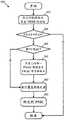
图11概念性地示出了当处理来自MPSE的数据分组时由MPRE执行的一些实施例的过程1100。在一些实施例中,处理1100由路由处理器1005执行。当MPRE接收到来自MPSE的数据分组时,过程1100开始。该过程基于例如网络段标识符(例如,VNI)识别(在1110处)用于入站数据分组(入站LIF)的逻辑接口。Figure 11 conceptually illustrates a
该过程然后确定(在1120处)入站LIF是用于桥接的逻辑接口(桥LIF)还是用于执行L3路由的逻辑接口(路由LIF)。在一些实施例中,逻辑接口或者被配置为路由LIF或者被配置为桥LIF。如果识别的入站LIF是桥LIF,则过程前进到1123。如果识别的入站LIF是路由LIF,则过程前进到1135。The process then determines (at 1120) whether the inbound LIF is a logical interface for bridging (bridge LIF) or a logical interface for performing L3 routing (routing LIF). In some embodiments, the logical interface is configured either as a routing LIF or as a bridge LIF. If the identified inbound LIF is a bridge LIF, the process proceeds to 1123. If the identified inbound LIF is a routing LIF, the process proceeds to 1135.
在1123处,该过程获知源MAC和到来分组的网络段标识符(例如,VNI)之间的配对。由于源MAC确定是在由VNI识别的网络段中,因此这个信息对于桥接具有相同MAC地址作为其目的地地址的分组是有用的。在一些实施例中,该信息被存储在桥表中,以提供在这个MAC地址与它的VNI之间的配对。At 1123, the process learns the pairing between the source MAC and the network segment identifier (eg, VNI) of the incoming packet. Since the source MAC is determined to be in a network segment identified by the VNI, this information is useful for bridging packets that have the same MAC address as their destination address. In some embodiments, this information is stored in a bridge table to provide a pairing between this MAC address and its VNI.
接下来,该过程确定(在1125处)在到来数据分组中的目的地MAC是否是需要桥接的MAC。需要桥接的目的地MAC是在源网络段中没有已知的目的地的MAC,并且不能被路由(例如,因为它与源VNI在同一IP子网上)。如果目的地MAC需要桥接,则过程前进到1130,否则,该过程结束。Next, the process determines (at 1125) whether the destination MAC in the incoming data packet is a MAC that needs to be bridged. The destination MAC that needs to be bridged is one that has no known destination in the source network segment and cannot be routed (eg, because it is on the same IP subnet as the source VNI). If the destination MAC requires bridging, the process proceeds to 1130, otherwise, the process ends.
在1130处,该过程通过根据桥接表将未知目的地MAC与VNI绑定执行桥接操作。在一些实施例中,如果没有找到这种条目,则过程泛洪附连到MPRE的所有其它桥LIF,以便找到匹配的用于未知目的地MAC的VNI。在一些实施例中,如果为这个桥LIF启用了防火墙,则该过程将不执行桥接。桥接操作将在下面的部分II.D中进一步描述。在一些实施例中,操作1130是由诸如定序器1030的顺序模块执行的顺序操作。在执行桥接之后,该过程前进到1150。At 1130, the process performs a bridging operation by binding the unknown destination MAC to the VNI according to the bridging table. In some embodiments, if no such entry is found, the process floods all other bridge LIFs attached to the MPRE in order to find a matching VNI for the unknown destination MAC. In some embodiments, if a firewall is enabled for this bridge LIF, the process will not perform bridging. Bridging operations are further described in Section II.D below. In some embodiments,
在1135处,该过程确定在到来数据分组中的目的地MAC是否寻址到MPRE。在一些实施例中,所有的MPRE回答通用的虚拟MAC地址(VMAC)作为目的地。在一些实施例中,在MPRE中的各个LIF回答其自己的LIF MAC(LMAC)作为目的地。如果目的地MAC地址用于MPRE(或LIF),则该过程前进到1140。否则,该过程1100结束。At 1135, the process determines if the destination MAC in the incoming data packet is addressed to the MPRE. In some embodiments, all MPREs answer a common virtual MAC address (VMAC) as the destination. In some embodiments, each LIF in the MPRE replies with its own LIF MAC (LMAC) as the destination. If the destination MAC address is for MPRE (or LIF), the process proceeds to 1140. Otherwise, the
在1140处,该过程解析(1140)到来数据分组中的目的地IP地址。在一些实施例中,MPRE首先尝试通过在ARP表中查找IP地址来在本地解析IP地址。如果在ARP表中没有找到匹配的条目,则该过程将发起ARP查询并且获取目的地MAC地址。ARP操作将在下面部分II.B中进一步描述。在一些实施例中,操作1140是由诸如定序器1030的顺序模块执行的顺序操作。At 1140, the process resolves (1140) the destination IP address in the incoming data packet. In some embodiments, the MPRE first attempts to resolve the IP address locally by looking up the IP address in the ARP table. If no matching entry is found in the ARP table, the process will initiate an ARP query and obtain the destination MAC address. ARP operation is further described in Section II.B below. In some embodiments,
该过程下一步识别(1150)用于到来分组的出站LIF(或者在这一点上更合适地,外出分组)。对于通过作为桥LIF的入站LIF进来的数据分组,出站LIF是由通过桥绑定提供的VNI识别的桥LIF。对于通过作为路由LIF的入站LIF进来的数据分组,一些实施例通过检查目的地IP地址识别出站LIF。在一些实施例中,出站LIF是由通过ARP解析表提供的VNI识别的路由LIF。The process next identifies (1150) the outbound LIF for the incoming packet (or more appropriately, the outgoing packet at this point). For data packets that come in through an inbound LIF that is a bridge LIF, the outbound LIF is the bridge LIF identified by the VNI provided through the bridge binding. For data packets that come in through an inbound LIF that is a routing LIF, some embodiments identify the outbound LIF by examining the destination IP address. In some embodiments, the outbound LIF is a routing LIF identified by the VNI provided through the ARP resolution table.
在识别出站LIF之后,该过程通过利用出站LIF将外出分组发送(在1160处)到正确的目的地段。在一些实施例中,出站LIF通过例如利用目的地段的网络段标识符标记外出分组来准备用于目的地段的分组。该过程1100然后结束。After identifying the outbound LIF, the process sends (at 1160) the outgoing packet to the correct destination segment by utilizing the outbound LIF. In some embodiments, the outbound LIF prepares packets for the destination segment by, for example, marking the outbound packet with the destination segment's network segment identifier. The
II.VDR分组处理操作II. VDR Packet Processing Operation
A.本地和远程访问MPREA. Local and Remote Access to MPRE
如所提到的,在以上部分I中描述的LRE是虚拟分布式路由器(VDR)。它将路由操作(无论L3层路由还是桥接)分布在不同主机中作为MPRE的LRE的不同具体实例上。在一些实施例中,采用VDR的逻辑网络通过使所有MPRE对所有虚拟机看起来相同进一步增强网络虚拟化。在这些实施例中的一些实施例中,每个MPRE可在L2数据链路层通过对于系统中所有MPRE都相同的MAC地址(VMAC)来寻址。这在本文被称为虚拟MAC地址(VMAC)。VMAC允许特定逻辑网络中的所有MPRE对于虚拟机和对于逻辑网络的用户(例如,网络管理员)看起来是一个连续的逻辑路由器。As mentioned, the LRE described in Section I above is a Virtual Distributed Router (VDR). It distributes routing operations (whether L3 layer routing or bridging) over different concrete instances of LREs that are MPREs in different hosts. In some embodiments, logical networking with VDR further enhances network virtualization by making all MPREs appear the same to all virtual machines. In some of these embodiments, each MPRE is addressable at the L2 data link layer by a MAC address (VMAC) that is the same for all MPREs in the system. This is referred to herein as a virtual MAC address (VMAC). VMAC allows all MPREs in a particular logical network to appear as one contiguous logical router to virtual machines and to users of the logical network (eg, network administrators).
但是,在一些实施例中,MPRE有必要彼此、与其它主机机器、或者与在其它主机机器中的网络元件(例如,在其它主机机器中的MPRE和/或VM)通信。在这些实施例中的一些实施例中,除了VMAC之外,每个MPRE可通过来自在物理网络上的其它主机机器的物理MAC(PMAC)地址唯一地寻址。在一些实施例中,用于寻址MPRE的这种唯一PMAC地址是分配给操作MPRE的主机机器的属性。由于MPRE可在其自己的逻辑网络内通过其主机机器的PMAC唯一地寻址,因此一些实施例将主机机器的这种唯一PMAC称为MPRE的唯一PMAC。在一些实施例中,由于用于不同租户的不同逻辑网络在主机机器内彼此安全地隔离,因此用于在同一主机机器上操作的不同租户的不同MPRE都可以使用那个主机机器的同一PMAC地址(以便可从其它主机机器寻址)。在一些实施例中,不仅每个MPRE与它的主机机器的PMAC相关联,而且每个逻辑接口与被称为LMAC的、其自己的唯一MAC地址相关联。However, in some embodiments, it is necessary for MPREs to communicate with each other, with other host machines, or with network elements in other host machines (eg, MPREs and/or VMs in other host machines). In some of these embodiments, in addition to the VMAC, each MPRE is uniquely addressable by physical MAC (PMAC) addresses from other host machines on the physical network. In some embodiments, this unique PMAC address used to address the MPRE is an attribute assigned to the host machine that operates the MPRE. Since the MPRE is uniquely addressable within its own logical network by the PMAC of its host machine, some embodiments refer to this unique PMAC of the host machine as the MPRE's unique PMAC. In some embodiments, since different logical networks for different tenants are securely isolated from each other within a host machine, different MPREs for different tenants operating on the same host machine can all use the same PMAC address of that host machine ( so that it can be addressed from other host machines). In some embodiments, not only is each MPRE associated with its host machine's PMAC, but each logical interface is associated with its own unique MAC address known as an LMAC.
在一些实施例中,每个离开MPRE的分组具有MPRE的VMAC作为源地址,但是在分组进入PNIC和离开主机到物理网络之前,主机机器将把源地址改变为主机机器的唯一PMAC。在一些实施例中,进入MPRE的每个分组必须具有MPRE的VMAC作为其目的地地址。对于从物理网络到达主机的分组,如果目的地地址是主机机器的唯一PMAC地址,则主机将把目的地MAC地址改变为通用的VMAC。在一些实施例中,主机机器的PMAC被实现为其上行链路模块的属性(例如,370),并且是上行链路模块将外出分组的源MAC地址从通用VMAC改变为其唯一PMAC和将到来分组的目的地地址从其唯一PMAC改变为通用VMAC。In some embodiments, each packet leaving the MPRE has the MPRE's VMAC as the source address, but the host machine will change the source address to the host machine's unique PMAC before the packet enters the PNIC and leaves the host to the physical network. In some embodiments, every packet entering the MPRE must have the MPRE's VMAC as its destination address. For packets arriving from the physical network to the host, if the destination address is the unique PMAC address of the host machine, the host will change the destination MAC address to a generic VMAC. In some embodiments, the PMAC of the host machine is implemented as a property of its uplink module (eg, 370), and it is the uplink module that changes the source MAC address of outgoing packets from the generic VMAC to its unique PMAC and the incoming The destination address of the packet is changed from its unique PMAC to a generic VMAC.
图12示出了用于一些实施例的、具有可通过共用VMAC和唯一PMAC寻址的MPRE的逻辑网络1200。如所示出的,逻辑网络1200包括两个不同的主机机器1201和1202。主机机器1201包括MPRE 1211、MPSE 1221和若干个虚拟机1231。主机机器1202包括MPRE 1212、MPSE1222和若干个虚拟机1232。这两个主机机器通过物理网络1290互连。MPSE 1222通过PNIC1282和上行链路模块1242从物理主机接收数据。Figure 12 illustrates a logical network 1200 with MPREs addressable by a common VMAC and unique PMAC for some embodiments. As shown, logical network 1200 includes two
在主机1201中的MPRE 1211可由VM 1231通过利用VMAC地址12:34:56:78:90:ab来寻址。在主机1202中的MPRE 1212也可由VM 1232通过相同的VMAC地址12:34:56:78:90:ab来寻址,即使MPRE 1211和MPRE 1212是在不同主机机器中的不同MPRE(对于同一LRE来说)。虽然没有被示出,但是在一些实施例中,在不同逻辑网络中用于不同租户的MPRE也可以使用相同的VMAC地址。
MPRE 1211和MPRE 1212中的每个也可被其它主机机器中的其它网络实体通过其自己的唯一PMAC地址从物理网络中寻址。如所示出的,MPRE 1211与其自己的唯一PMAC地址11:11:11:11:11:11(PMAC1)相关联,而MPRE 1212与其自己的唯一PMAC地址22:22:22:22:22:22(PMAC2)相关联。Each of
图12还示出了发送到另一个主机机器上的远程MPRE的数据流量的例子。与MPRE不同,远程MPRE不能直接通过用于从物理网络到来的分组的通用VMAC来寻址。在远程主机中的MPRE只能通过那个远程MPRE的唯一PMAC地址来寻址。在远程主机上运行的虚拟化软件在一些实施例中在执行L2交换之前将唯一PMAC地址改变回到通用VMAC地址。Figure 12 also shows an example of data traffic sent to a remote MPRE on another host machine. Unlike MPREs, remote MPREs cannot be directly addressed by the generic VMAC used for packets arriving from the physical network. An MPRE in a remote host can only be addressed by the unique PMAC address of that remote MPRE. The virtualization software running on the remote host changes the unique PMAC address back to the generic VMAC address in some embodiments before performing L2 switching.
图12示出了在四个标记为“1”、“2”、“3”和“4”的操作中从主机1201中的MPRE 1211到主机1202中的MPRE 1212的流量。在操作“1”中,VM 1231利用通用VMAC地址将分组发送到其MPRE 1211。这个分组也将具有对应于该流量的期望目的地的目的地IP地址(未示出)。在操作“2”中,主机1201的MPRE 1211通过利用MPRE 1212的唯一物理MAC“PMAC2”作为目的地地址将分组发送到主机1202的MPRE 1212。为了执行这一转换,在一些实施例中,MPRE 1211将在其ARP表中查找(或执行ARP)来识别对应于目的地IP地址的目的地MAC地址(PMAC2)。Figure 12 shows traffic from
在操作“3”中,数据分组已通过其物理NIC到达主机1202并且到达上行链路模块1242(在主机1202上运行的虚拟化软件的一部分)。上行链路模块1242又将MPRE 1212的唯一PMAC(“PMAC2”)转换为通用VMAC作为目的地地址。在操作“4”中,数据分组到达MPSE1222,其基于通用VMAC将分组转发到MPRE 1212。In operation "3", the data packet has reached the
图13示出了使用用于网络1200的共用VMAC和唯一PMAC从一个VM到另一个VM路由的L3网络流量的例子。该网络流量是源自主机机器1201中的VM 1331并且去往主机机器1202中的VM 1332的数据分组。该示例路由的L3流量在标记为“1”至“4”的四个操作中示出。在操作“1”期间,具有链路层L2地址“MAC1”的VM 1331通过利用MPRE的共用VMAC作为目的地地址将数据分组发送到MPRE 1211。在操作“2”期间,MPRE 1211通过将目的地IP地址解析为用于具有链路层L2地址“MAC2”的目的地VM的目的地MAC地址来执行L3层路由。MPRE 1211还利用其自己的唯一物理链路层地址“PMAC1”(11:11:11:11:11:11)替代VM 1331的MAC地址“MAC1”作为源MAC地址。在操作“3”中,路由的分组到达MPSE1222,其根据目的地MAC地址“MAC 2”将数据分组转发到目的地VM 1232。在操作“4”中,数据分组到达目的地虚拟机1232。在一些实施例中,当唯一PMAC是源地址时,没有必要将唯一PMAC(在这种情况下,“PMAC1”)改变为通用VMAC,这是因为VM 1332忽略标准(非ARP)数据流量的源MAC地址。13 shows an example of L3 network traffic routed from one VM to another using a common VMAC and unique PMAC for network 1200. The network traffic is data packets originating from
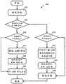
如所提到的,上行链路模块是对从PNIC到MPSE的到来数据执行预处理和对从MPSE到PNIC的外出数据执行后处理的模块。图14概念性地示出了用于通过上行链路模块(诸如1242)执行的预处理操作的过程1400。在一些实施例中,过程1400的操作被实现为从PNIC进入主机机器的入口管道。As mentioned, the uplink module is a module that performs preprocessing on incoming data from PNIC to MPSE and post-processing on outgoing data from MPSE to PNIC. 14 conceptually illustrates a
当该过程从PNIC(即,从外部物理网络)接收(在1410处)分组时,该过程开始。如果数据是用于诸如VXLAN或VLAN的覆盖网络,则该过程执行(在1420处)覆盖网络处理。当在远程主机上的VM向在同一VXLAN网络中但是在这个主机上的VM发送数据分组时,该过程将在让分组通过MPSE被转发到VM之前使分组去封装。通过执行这个操作,上行链路模块允许主机用作用于VXLAN的隧道端点(例如,VTEP)。The process begins when a packet is received (at 1410) from the PNIC (ie, from an external physical network). If the data is for an overlay network such as VXLAN or VLAN, the process performs (at 1420) overlay network processing. When a VM on a remote host sends a data packet to a VM in the same VXLAN network but on this host, the process will decapsulate the packet before letting the packet be forwarded to the VM over MPSE. By doing this, the uplink module allows the host to act as a tunnel endpoint (eg, VTEP) for the VXLAN.
接下来,该过程确定(在1430处)在到来数据分组中的目的地MAC是否是唯一物理MAC(PMAC)。在一些实施例中,唯一PMAC地址用于将数据分组定向到特定的主机,但是不能用来将分组发送到主机的MPRE中(因为MPSE将用于MPRE的端口与VMAC而不是PMAC相关联)。如果目的地MAC是唯一PMAC,则该过程前进到1445。否则,该过程进行到1435。Next, the process determines (at 1430) whether the destination MAC in the incoming data packet is a unique physical MAC (PMAC). In some embodiments, a unique PMAC address is used to direct data packets to a particular host, but cannot be used to send packets into the host's MPRE (because the MPSE associates the port for the MPRE with the VMAC rather than the PMAC). If the destination MAC is the only PMAC, the process proceeds to 1445. Otherwise, the process proceeds to 1435.
在1435处,该过程确定在到来数据分组中的目的地MAC是否是广播MAC(例如,ff:ff:ff:ff:ff:ff)。在一些实施例中,主机将接受广播MAC,但是一些广播分组必须首先被MPRE处理,而不是被发送到连接到MPSE的每个VM。如果目的地MAC是广播MAC,则该过程前进到1440查看是否广播分组需要到MPRE。否则该过程前进到1450,以允许分组到MPSE而无需改变目的地MAC。At 1435, the process determines whether the destination MAC in the incoming data packet is a broadcast MAC (eg, ff:ff:ff:ff:ff:ff). In some embodiments, the host will accept broadcast MACs, but some broadcast packets must first be processed by the MPRE rather than being sent to every VM connected to the MPSE. If the destination MAC is a broadcast MAC, the process proceeds to 1440 to see if the broadcast packet needs to go to the MPRE. Otherwise the process proceeds to 1450 to allow the packet to the MPSE without changing the destination MAC.
在1440处,该过程确定具有广播MAC的分组是否需要被转发到MPRE。在一些实施例中,只有某些类型的广播消息是MPRE感兴趣的,并且只有这些类型的广播消息需要把其广播MAC地址改变为通用VMAC。例如,广播ARP查询消息是MPRE是感兴趣的并且将通过把其目的地MAC地址改变为VMAC而被转发到MPRE。如果广播分组是MPRE感兴趣的,则该过程前进到1445。否则该过程前进到1450。At 1440, the process determines whether the packet with the broadcast MAC needs to be forwarded to the MPRE. In some embodiments, only certain types of broadcast messages are of interest to the MPRE, and only these types of broadcast messages need to have their broadcast MAC address changed to a generic VMAC. For example, a broadcast ARP query message is of interest to the MPRE and will be forwarded to the MPRE by changing its destination MAC address to VMAC. If the broadcast packet is of interest to the MPRE, the process proceeds to 1445. Otherwise the process proceeds to 1450.
在1445处,该过程用通用VMAC替换目的地MAC(或者PMAC或广播),这确保具有这些目的地MAC的分组将被MPRE处理。该过程然后前进到1450,以允许分组带着被改变的目的地MAC前进到MPSE。该过程1400然后结束。At 1445, the process replaces the destination MACs (or PMACs or broadcasts) with generic VMACs, which ensures that packets with these destination MACs will be processed by the MPRE. The process then proceeds to 1450 to allow the packet to proceed to the MPSE with the changed destination MAC. The
图15概念性地示出了用于通过上行链路模块执行的后处理操作的过程1500。在一些实施例中,过程1500的操作被实现为用于通过PNIC离开主机机器的分组的出口管道。该过程在它在上行链路模块处从MPSE接收到(在1510处)分组时启动。该过程然后确定(在1520处)分组是否要去远程主机。如果分组的目的地地址指示在本地主机机器内的端口(例如,MPRE或其中一个VM),则该过程忽略分组并且结束。否则,该过程前进到1530。15 conceptually illustrates a
在1530处,该过程确定源MAC地址是否是通用VMAC,即,分组是否来自MPRE。如果是,则该过程前进到1540。否则,该过程前进到1550。在1540处,该过程用MPRE的唯一PMAC替换VMAC作为源MAC地址。这确保分组的接收者将能够通过利用其唯一PMAC地址正确地识别发送者MPRE。At 1530, the process determines whether the source MAC address is a generic VMAC, ie, whether the packet is from an MPRE. If so, the process proceeds to 1540. Otherwise, the process proceeds to 1550. At 1540, the process replaces the VMAC with the MPRE's unique PMAC as the source MAC address. This ensures that the recipient of the packet will be able to correctly identify the sender MPRE by utilizing its unique PMAC address.
如果数据要去诸如VXLAN或VLAN的覆盖网络,则该过程然后执行(在1550处)覆盖网络处理。当主机上的VM将数据分组发送到在同一VXLAN网络但是在不同主机上的另一个VM时,该过程将在把帧注入到物理网络之前利用VXLAN网络的VNI封装帧。通过执行这一操作,上行链路模块允许主机用作VXLAN(VTEP)下的隧道端点。接下来,该过程将分组转发(在1560处)到物理NIC。该过程1500然后结束。If the data is going to an overlay network such as a VXLAN or VLAN, the process then performs (at 1550) overlay network processing. When a VM on a host sends a data packet to another VM on the same VXLAN network but on a different host, the process will encapsulate the frame with the VXLAN network's VNI before injecting the frame into the physical network. By doing this, the uplink module allows the host to act as a tunnel endpoint under VXLAN (VTEP). Next, the process forwards (at 1560) the packet to the physical NIC. The
B.利用VDR执行地址解析B. Use VDR to perform address resolution
如所提到的,每个LRE具有一组用于与每个网络段中的虚拟机接口的逻辑接口。在一些实施例中,从虚拟机的角度看,网络段的逻辑接口也用作网络段中的虚拟机的缺省网关。由于LRE操作在每个主机机器中的MPRE,因此,在一些实施例中,为它其中一个逻辑接口接收ARP查询(诸如用于缺省网关的ARP)的MPRE在本地响应查询而不将该查询转发到其它主机机器。As mentioned, each LRE has a set of logical interfaces for interfacing with virtual machines in each network segment. In some embodiments, from the perspective of the virtual machine, the logical interface of the network segment also serves as the default gateway for the virtual machines in the network segment. Since the LRE operates an MPRE in each host machine, in some embodiments, the MPRE that receives an ARP query (such as ARP for the default gateway) for one of its logical interfaces responds to the query locally without the query Forward to other host machines.
图16示出了用于在逻辑网络1600中的VDR/LRE MPRE的逻辑接口的ARP查询操作。逻辑网络1600跨至少两个主机机器1601和1602分布。主机机器1601具有MPRE 1611并且主机机器1602具有MPRE 1612。每个MPRE具有用于逻辑网络的段A的逻辑接口(LIF A)和用于段B的逻辑接口(LIF B)。(MPRE 1611具有LIF A 1621和LIF B 1631;MPRE 1612具有LIF A1622和LIF B 1632)。主机机器1601具有使用MPRE 1611的LIF A的段A VM 1629。主机机器1602具有使用MPRE 1612的LIF B的段B VM 1639。FIG. 16 shows an ARP query operation for a logical interface of a VDR/LRE MPRE in logical network 1600. The logical network 1600 is distributed across at least two
每个LIF与IP地址相关联。但是,如所示出的,MPRE 1611的LIF A 1621和MPRE1612的LIF A 1622两者都具有相同的IP地址(10.1.1.253)。这是段A的缺省网关的IP地址(子网10.1.1.x)。类似地,MPRE 1611的LIF B 1631和MPRE 1612的LIF B 1632两者都具有相同的IP地址(10.1.2.253)。这是段B的缺省网关的IP地址(子网10.1.2.x)。Each LIF is associated with an IP address. However, as shown, both LIF A 1621 of
该图示出了在标记为“1”至“6”的操作中由VM 1629和1639做出的两个ARP查询。在操作“1”中,段A的虚拟机1629做出对其段的缺省网关的ARP查询。该ARP查询消息使用LIF A的IP地址(10.1.1.253)作为目的地IP和使用广播MAC作为目的地MAC地址。在操作“2”期间,LIF A 1621通过将IP地址“10.1.1.253”解析为用于所有MPRE的VMAC地址来响应ARP查询。此外,LIF A 1621不把ARP查询消息传递到物理网络上。这防止在网络中具有与LIF A相同IP地址“10.1.1.253”的其它实体响应,该其它实体诸如在其它主机机器中的其它VDR/LREMPRE上的LIF A(例如,在主机机器1602上的LIF A 1622)。在操作“3”中,VM 1629接收ARP应答消息并且更新其将缺省网关的IP地址解析为MAC地址“VMAC”的解析表。这个应答消息的目的地MAC地址是原始询问者的MAC地址(即,用于VM 1629的“MAC1”),并且源MAC地址是新解析的MPRE的MAC地址“VMAC”。VM 1629然后将这一条目存储在其解析表中,用于后续对MPRE 1611的访问,以便为后续发送的需要被路由的分组寻址。操作“4”、“5”和“6”是类似于操作“1”、“2”和“3”的操作,其中MPRE 1612的LIF B 1632响应于由段B VM 1639进行的ARP请求,而无需将ARP查询消息传递到物理网络上。虽然由VM 1639进行的ARP请求被发送到不同MPRE上的不同LIF,但是同一地址“VMAC”被用在ARP应答中。The figure shows two ARP queries made by
一旦虚拟机知道缺省网关的MAC地址,它就可以通过利用VMAC寻址MPRE的逻辑接口将数据分组发送到其它网络段。但是,如果MPRE不知道目的地IP地址(例如,用于目的地虚拟机)所解析到的链路层MAC地址,则MPRE将需要解析这个地址。在一些实施例中,MPRE可以从其它主机机器中的同一LRE的其它MPRE或者从控制器集群获得这种地址解析信息。在一些实施例中,MPRE可以在目的地虚拟机的网络段中发起其自己的ARP查询来确定它的MAC地址。当做出这种ARP请求时,MPRE使用它自己的唯一PMAC地址,而不是通用VMAC地址作为用于发送到去往其它MPRE的物理网络上的分组的源地址。Once the virtual machine knows the MAC address of the default gateway, it can send data packets to other network segments by addressing the MPRE's logical interface using the VMAC. However, if the MPRE does not know the link layer MAC address to which the destination IP address (eg, for the destination virtual machine) resolves, the MPRE will need to resolve this address. In some embodiments, the MPRE may obtain such address resolution information from other MPREs of the same LRE in other host machines or from the controller cluster. In some embodiments, the MPRE may initiate its own ARP query in the network segment of the destination virtual machine to determine its MAC address. When making such ARP requests, the MPRE uses its own unique PMAC address, rather than the generic VMAC address, as the source address for packets sent on the physical network destined for other MPREs.
图17示出了一些实施例的MPRE发起的ARP查询。具体而言,该图示出了逻辑网络1700的实现,其中MPRE使用其自己的PMAC地址用于发起其自己的ARP查询。如所示出的,逻辑网络1700的实现包括至少两个主机机器1701和1702。驻留在主机机器1701上的是在段A中的VM 1731、具有用于段A的逻辑接口1721的MPRE 1711、以及用于从物理网络接收数据的上行链路模块1741。驻留在主机机器1702上的是在段B中的VM 1732、具有用于段B的逻辑接口1722的MPRE 1712、以及用于从物理网络接收数据的上行链路模块1742。除了通用VMAC之外,MPRE 1711具有唯一物理MAC地址“PMAC1”,并且MPRE 1712具有唯一物理MAC地址“PMAC2”。Figure 17 illustrates an MPRE-initiated ARP query of some embodiments. Specifically, the figure shows an implementation of
在标记为“1”至“8”的操作中,该图示出了由来自主机1701的MPRE 1711发起对于段B中的VM 1732的ARP查询。在操作“1”期间,具有IP地址10.1.1.1的VM 1731(在段A中)发送分组到目的地网络层地址10.1.2.1(在段B中),这需要通过其MPRE 1711进行的L3路由。VM 1731已知道其缺省网关的L2链路层地址是“VMAC”(例如,从先前的ARP查询得知)并且因此它通过利用VMAC将数据分组直接发送到MPRE 1711,这是因为目的地IP是在另一个段中。In operations labeled "1" through "8", the figure shows an ARP query for
在操作“2”期间,MPRE 1711确定它不具有用于目的地VM 1732的L2链路层地址(例如,通过检查它的地址解析表得知),并且因此发起对目的地IP“10.1.2.1”的ARP查询。这个ARP查询使用MPRE1711的唯一物理MAC地址(“PMAC1”)作为源MAC地址和使用广播MAC地址作为目的地MAC。MPRE 1711还对分组执行L3路由,以确定目的地IP“10.1.2.1”是在段B中,并且它因此将源IP改变为“10.1.2.253”(即,LIF B的IP地址)。这个广播ARP消息穿过物理网络到达主机1702。在一些实施例中,如果逻辑网络跨越附加的主机(即,具有附加的本地LRE具体实例作为MPRE的附加主机),则ARP消息也将被发送到这些其它主机。During operation "2",
在操作“3”期间,广播ARP查询到达运行在主机1702上的上行链路模块1742,其又用对所有MPRE通用的“VMAC”替换广播MAC地址(“ffffffffffff”),使得在主机1702中的MPSE将把ARP查询分组转发到MPRE 1712。但是,对发送者MPRE 1711唯一的源地址“PMAC1”保留在修改的ARP查询中。During operation "3", the broadcast ARP query reaches the
在操作“4”期间,因为主机1702的MPRE 1712看到VMAC是目的地地址,因此它接收ARP查询。MPRE 1712不能解析目的地IP地址10.1.2.1,因此它又通过LIF B 1722将该ARP查询作为广播(目的地“ffffffffffff”)转发到段B上的主机1702的任何本地VM,包括VM1732。该ARP查询通过用于VM 1732的出站LIF 1722(用于B段)从MPRE 1712出来。During operation "4", because the
在操作“5”期间,具有“VMAC”作为源MAC地址的广播ARP查询到达VM 1732并且VM1732通过LIF B 1722向MPRE 1712发送对ARP查询的应答消息。在应答消息中,VM 1732指示对应于L3网络层地址“10.1.2.1”的L2层链路地址是其地址“MAC2”,并且应答要利用通用MAC地址“VMAC”发送到请求的MPRE 1712。MPRE 1712还为“10.1.2.1”更新其自己的ARP解析表1752,以便它将来可以充当ARP代理。During operation "5", a broadcast ARP query with "VMAC" as the source MAC address reaches
在操作“6”期间,基于由MPRE 1712存储的、来自它对其做出响应的ARP查询的信息(指示IP 10.1.1.253解析为MAC“PMAC1”),MPRE 1712通过利用“PMAC1”作为目的地MAC地址将应答分组转发回给进行查询的MPRE 1711。在操作“7”期间,用于主机1702的上行链路模块1741将唯一“PMAC1”转换为通用“VMAC”,使得在主机1701处的MPSE将把分组在本地转发到MPRE 1711。最后,在操作“8”处,应答消息到达原始查询的MPRE 1711,其由在其自己的解析表1751中存储用于IP地址10.1.2.1(即,“MAC2”)的地址解析,以便它将能够把分组从VM1731转发到VM 1732。这时,最初由VM 1731发送的数据分组可以被路由用于交付到VM 1732并且可以朝着主机1702被发送到物理网络上。During operation "6", based on the information stored by
因为MPRE 1712自己不能为VM 1732解析地址,因此它必须继续传递ARP询问。但是,一旦MPRE 1712接收到来自VM 1732的ARP应答,它就能够自己响应对地址10.1.2.1的后续ARP查询,而无需必须继续传递ARP询问。图18示出了MPRE 1712在网络1700中充当用于响应MPRE 1712能够解析的ARP询问的代理。Because
图18示出了具有来自前面的图的主机1702以及另一个主机机器1703的网络1700。在主机1702中的MPRE 1712的ARP解析表1752已经具有用于为VM 1732解析IP地址10.1.2.1的条目。驻留在主机1703上的是在逻辑网络的段D上的VM 1733、具有用于段D的逻辑接口1724的MPRE 1713、以及用于从物理网络接收数据的上行链路模块1743。除了通用VMAC之外,MPRE 1713具有唯一物理MAC地址“PMAC3”。在标记为“1”至“6”的操作中,该图示出了由来自主机机器1703的MPRE 1713为段B中的VM 1732发起的ARP查询。Figure 18 shows a
在操作“1”期间,具有IP地址10.1.5.1(在段D中)的VM 1733发送分组到目的地网络层地址10.1.2.1(在段B中),这需要通过其MPRE 1713进行的L3路由。VM 1733已知道其缺省网关的L2链路层地址是“VMAC”(例如,从先前的ARP查询得知)并且因此它通过利用VMAC将数据分组直接发送到MPRE 1713,这是因为目的地IP是在另一个段中。During operation "1",
在操作“2”期间,MPRE 1713意识到它不具有用于目的地VM 1732的L2链路层地址(例如,通过检查它的地址解析表得知),并且因此发起对目的地IP“10.1.2.1”的ARP查询。这个ARP查询使用MPRE 1713的唯一物理MAC地址(“PMAC3”)作为源MAC地址和使用广播MAC地址作为目的地MAC。MPRE 1713还对分组执行L3路由,以确定目的地IP“10.1.2.1”是在段B中,并且它因此将源IP改变为“10.1.2.253”(即,LIF B的IP地址)。这个广播ARP消息穿过物理网络到达主机1702。此外,虽然没有示出,但是广播ARP消息也将到达主机1701,这是因为这个主机具有MPRE 1711。During operation "2",
在操作“3”期间,广播ARP查询到达运行在主机1702上的上行链路模块1742,其又用对所有MPRE通用的“VMAC”替换广播MAC地址(“ffffffffffff”),使得在主机1702中的MPSE将把ARP查询转发到MPRE 1712。但是,对发送者MPRE 1713唯一的源地址“PMAC3”保留在修改的ARP查询中。During operation "3", the broadcast ARP query reaches the
在操作“4”期间,MPRE 1712检查其自己的解析表1752并且意识到它能够将IP地址10.1.2.1解析到MAC2。因此,MPRE通过物理网络将ARP应答发送到目的地地址“PMAC3”,而不是将ARP查询转发到其所有段B VM。在这种情况下,在ARP应答操作中不涉及LIF B 1722和VM 1732。During operation "4",
在操作“5”期间,用于主机1703的上行链路模块1743将唯一“PMAC3”转换为通用“VMAC”,使得在主机1703处的MPSE将把分组在本地转发到MPRE 1713。最后,在操作“6”处,应答消息到达原始查询的MPRE 1713,其又在其自己的解析表1753中存储用于IP地址10.1.2.1(即,“MAC2”)的地址解析,以便它将能够把分组从VM 1733转发到VM 1732。这时,最初由VM 1733发送的数据分组可以被路由用于交付到VM 1732并且可以朝着主机1702被发送到物理网络上。During operation "5", the
图17和18示出了在对于与发送者MPRE处于不同主机机器中的虚拟机的ARP询问中使用唯一PMAC。但是,在一些实施例中,这个ARP机制对于解析在与发送者MPRE相同的主机机器中操作的虚拟机的地址也一样能很好地工作。图19示出了在对于与发送者MPRE处于相同主机机器中的虚拟机的ARP询问中使用唯一PMAC。Figures 17 and 18 illustrate the use of a unique PMAC in an ARP query to a virtual machine that is in a different host machine than the sender MPRE. However, in some embodiments, this ARP mechanism also works well for resolving addresses of virtual machines operating in the same host machine as the sender MPRE. Figure 19 illustrates the use of a unique PMAC in an ARP query to a virtual machine in the same host machine as the sender MPRE.
图19示出了在图17的网络1700中发生的另一个ARP查询。如在图19中所示,除了MPRE 1712之外,也驻留在主机1702中的是另一个段B VM 1734和段C VM 1735。MPRE 1712具有用于与段C中的VM,诸如VM 1735,接口的逻辑接口1723。图19示出了由MPRE 1712发起的ARP操作。这个ARP操作被启动是因为MPRE 1712必须将来自在段C中的VM 1735的分组路由到在段B中的VM 1734,这两个VM都驻留在主机1702上。与在图17中示出的、其中发起的MPRE 1711是询问在另一个主机机器中的VM的ARP操作不同,在图19中示出的ARP操作是用于位于与发起的MPRE 1712处于同一主机机器中的VM。FIG. 19 shows another ARP query taking place in the
在标记为“1”至“9”的操作中,该图示出了由MPRE 1712发起的对于在段B中的VM1734的ARP查询。在操作“1”期间,具有IP地址10.1.3.1(在段C)的VM 1731发送分组到目的地网络层地址10.1.2.2(在段B中),这需要通过其MPRE 1712进行的L3路由。VM 1735已知道其缺省网关的L2链路层地址是“VMAC”(例如,从先前的ARP查询得知)并且因此它通过利用VMAC将数据分组直接发送到MPRE 1712,这是因为目的地IP是在另一个段中。In operations labeled "1" through "9", the figure shows an ARP query initiated by
在操作“2”期间,MPRE 1712确定它不具有用于目的地VM 1734的L2链路层地址(例如,通过检查它的地址解析表得知),并且因此发起对在网络段B中的目的地IP“10.1.2.2”的ARP查询。该ARP查询将被广播到段B上的主机1702的所有本地VM以及到其它主机(诸如主机1701)。During operation "2",
在操作“3”期间,MPRE 1712通过LIF B 1722将ARP查询广播到本地段B VM,包括VM1734。由于这个广播位于主机1702内,因此源地址仍然是通用VMAC。在操作“4”期间,在主机1702内(在段B上)本地广播的ARP查询到达VM 1734并且VM 1734对ARP查询发送应答消息。During operation "3",
与操作“3”和“4”同时,MPRE 1712在操作“5”期间也向其它主机广播ARP请求。该广播消息使用广播MAC地址作为其目的地MAC和MPRE 1712的唯一PMAC“PMAC2”作为源MAC地址(例如,如在被发送到物理NIC之前通过上行链路修改的)。MPRE 1712还对分组执行L3路由以确定目的地IP“10.1.2.2”是在段B中,并且因此将源IP改变为“10.1.2.253”(即,LIF B的IP地址)。在操作“6”中的广播ARP到达主机1701,其上行链路模块1741将目的地MAC修改为用于其MPRE 1711的通用VMAC。但是,将没有来自其它主机的ARP应答,这是因为将没有对IP10.1.2.2的匹配(虽然在一些实施例中,这些主机将把ARP转发到其段B VM上)。Concurrent with operations "3" and "4",
在操作“7”期间,VM 1734生成对在操作“4”期间接收到的ARP查询的应答消息。应答消息指示L2地址“MAC4”对应于所请求的L3网络层地址“10.1.2.2”,并且该应答要利用其通用MAC地址“VMAC”被发送到请求的MPRE。在操作“8”期间,由VM 1734生成的ARP应答通过LIF B 1722进入MPRE 1712。最后,在操作“9”处,MPRE 1712将用于IP地址10.1.2.2(即,“MAC4”)的地址解析存储在其自己的解析表1752中,使得它将能够把分组从VM 1735转发到VM 1734(包括初始发送的数据分组)。During operation "7",
图20和21示出了用于在MPRE已更新其解析表之后在不同段的VM之间发送数据流量的操作。具体而言,图20和21示出了在主机1701的MPRE 1711和MPRE 1712已通过先前的ARP查询更新了其解析表(如在图17和19中所示出的)之后在VM 1731、1732和1735之间的网络1700的数据流量。Figures 20 and 21 illustrate operations for sending data traffic between VMs of different segments after the MPRE has updated its resolution table. In particular, Figures 20 and 21 show
图20示出了将数据分组从段A VM 1731和段C VM 1735路由到段B VM 1732。路由发生在MPRE 1711和1712中,其中MPRE是分别用于发送方VM 1731和发送方VM 1735的。MPRE1711使用解析表1751用于路由查找,而MPRE 1712使用解析表1752用于路由查找。20 illustrates routing of data packets from
操作“1”至“3”示出了数据分组从段A VM 1731到段B VM 1732的路由。在操作“1”中,VM 1731利用通用VMAC将分组发送到MPRE 1711的LIF A 1721。该分组去往IP地址10.1.2.1,它与VM 1731(IP地址10.1.1.1)处于不同的网络段中,并且因此需要L3层路由。在操作“2”期间,MPRE 1711通过利用在解析表1751中的条目(即,如通过图17所示的操作获知的)将IP地址10.1.2.1解析为L2地址“MAC2”和段B。MPRE 1711使用其自己的唯一L2地址“PMAC1”作为用于发送出到物理网络上的分组的源地址。MPRE 1711还识别LIF B 1725作为出站LIF并且使用该LIF跨物理网络(标记有段B的网络标识符)将分组发送到主机1702。在操作“3”期间,路由的分组已穿越整个物理网络并且到达其L2地址是“MAC2”的目的地VM1732。Operations "1" through "3" illustrate the routing of data packets from
操作“4”至“6”示出了数据分组从段C VM 1735到段B VM 1732的路由,其中数据分组不需要离开主机1702。在操作“4”期间,VM 1735利用通用VMAC作为分组的目的地MAC将分组发送到MPRE 1712的LIF C 1723。该分组去往IP地址10.1.2.1,它在与VM 1735(IP地址10.1.3.1)不同的网络段上,并且因此需要L3路由。在操作“5”期间,MPRE 1712通过利用解析表1752中的条目将IP地址10.1.2.1解析为L2地址“MAC2”。因为该分组从未离开主机1702到物理网络,因此MPRE 1712也使用VMAC作为源L2 MAC地址。MPRE 1712已识别LIF B 1722作为出站LIF并且使用该LIF将分组发送到本地段B VM 1732。在操作“6”期间,数据分组到达其MAC地址是“MAC2”的目的地VM 1732。Operations "4" through "6" illustrate the routing of data packets from
图21示出了数据分组从段B VM 1732发送到段A VM 1731和段C VM 1735的路由。路由发生在MPRE 1712中,它是用于发送者VM 1732的本地路由器实例。如前所述,MPRE1712依靠解析表1752用于路由查找。MPRE 1712具有用于与段B中的VM,诸如VM 1732接口的逻辑接口1722(LIF B)。MPRE 1712具有用于与段C中的VM,诸如VM 1735接口的逻辑接口1723(LIF C)。MPRE 1712还具有用于与段A中的VM,诸如VM 1731接口的逻辑接口1725(LIFA)。21 shows the routing of data packets from
操作“1”至“3”示出数据分组从段B VM 1732到段A VM 1731的路由。在操作“1”期间,VM 1732利用通用VMAC作为目的地MAC将分组发送到MPRE 1712的LIF B 1722。该分组去往IP地址10.1.1.1,它在与VM 1732(IP地址10.1.2.1)不同的网络段中,并且需要L3层路由。数据分组通过将LIF B 1722用作入站LIF进入MPRE 1712。在操作“2”期间,MPRE 1712通过利用在解析表1752中的条目将IP地址10.1.1.1解析为L2地址“MAC1”。MPRE 1711也识别LIF A 1726作为出站LIF和使用LIF A将分组跨物理网络(标记有段A的VNI)发送到主机1701。在一些实施例中,MPRE 1711也利用其自己的唯一L2地址“PMAC2”替代通用“VMAC”作为源MAC地址。在操作“3”期间,路由的分组到达其MAC地址是“MAC1”的目的地VM 1731。Operations "1" through "3" illustrate the routing of data packets from
操作“4”至“6”示出了数据分组从段B VM 1732到段C VM 1735的路由。在操作“4”期间,VM 1732利用通用VMAC作为分组的目的地MAC地址将分组发送到MPRE 1712的LIF B1722。该分组去往IP地址10.1.3.1,它在与VM 1732(IP地址10.1.2.1)不同的网络段中并且因此需要L3路由。在操作“5”期间,MPRE 1712通过利用解析表1752中的条目将IP地址10.1.3.1解析为L2地址“MAC3”。由于目的地L2地址“MAC3”指示在与MPRE 1712相同的主机机器(主机1702)中操作的虚拟机,因此在一些实施例中,MPRE将不把数据分组发送到物理网络上。因为该分组从未离开主机1702到物理网络,因此MPRE 1712也使用VMAC作为源L2MAC地址。MPRE 1712也识别LIF C 1723作为出站LIF并且使用这个LIF将分组发送到本地段C VM 1735。在操作“6”期间,分组到达其MAC地址是“MAC3”的目的地VM 1735。Operations "4" through "6" illustrate the routing of data packets from
对于一些实施例,图22概念性地示出了由一些实施例的MPRE具体实例执行的、用于为到来数据分组处理地址解析的过程2200。当过程2000接收到(在2210处)数据分组(例如,来自MPSE的)时,该过程开始。该数据分组可以是需要被路由或转发的常规数据分组,或者是需要应答的ARP查询。接下来,该过程确定(在2220处)接收到的分组是否是ARP查询。如果该数据分组是ARP查询,则过程前进到2225。否则,过程前进到2235。For some embodiments, Figure 22 conceptually illustrates a
在2225处,该过程确定它是否能够为ARP查询解析目的地地址。在一些实施例中,该过程检查其自己的ARP解析表,以确定是否存在相应的用于解析该分组的网络层IP地址的条目。如果过程能够解析该地址,则它前进到2260。如果过程不能解析该地址,则它前进到2230。At 2225, the process determines if it can resolve the destination address for the ARP query. In some embodiments, the process checks its own ARP resolution table to determine if there is a corresponding entry for the network layer IP address used to resolve the packet. If the process can resolve the address, it proceeds to 2260. If the process cannot resolve the address, it proceeds to 2230.
在2230处,过程转发ARP查询。如果ARP请求来自物理网络,则过程将ARP查询转发到本地主机内的VM。如果ARP请求来自在本地主机中的VM,则该过程将请求转发到在本地主机机器中的其它VM以及转发出到物理网络以被在其它主机机器中的MPRE处理。该过程然后等待和接收(在2250处)ARP应答并且基于应答消息更新其ARP解析表。过程2200然后应答(在2260处)ARP查询消息并且结束。At 2230, the process forwards the ARP query. If the ARP request is from the physical network, the process forwards the ARP query to the VM within the local host. If the ARP request is from a VM in the local host, the process forwards the request to other VMs in the local host machine and out to the physical network for processing by MPRE in the other host machine. The process then waits for and receives (at 2250) an ARP reply and updates its ARP resolution table based on the reply message.
在2235处,该过程确定它是否能够为到来数据分组解析目的地地址。如果该过程能够解析目的地地址(例如,具有匹配的ARP解析表条目),则该过程前进到2245。否则,该过程前进到2240。At 2235, the process determines if it can resolve the destination address for the incoming data packet. If the process is able to resolve the destination address (eg, has a matching ARP resolution table entry), the process proceeds to 2245. Otherwise, the process proceeds to 2240.
在2240处,该过程产生ARP查询并且通过其出站LIF向远程主机机器以及本地虚拟机广播该ARP查询。该过程然后接收(在2242处)对其ARP查询的应答并且更新其ARP表。该过程2200然后根据解析的MAC地址转发(在2245处)数据分组并且结束。At 2240, the process generates an ARP query and broadcasts the ARP query through its outbound LIF to the remote host machine and the local virtual machine. The process then receives (at 2242) the reply to its ARP query and updates its ARP table. The
C.VDR作为用于非-VDR主机机器的路由代理C. VDR as a routing proxy for non-VDR host machines
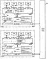
在一些实施例中,不是在底层物理网络上产生和接受网络流量的所有主机机器都运行虚拟化软件和操作VDR。在一些实施例中,这些主机中的至少一些是根本不运行虚拟化软件并且不托管任何虚拟机的物理主机机器。这些非-VDR物理主机机器中的一些是构建在底层物理网络中的遗留网络元件(诸如文件服务器或另一个非管理程序/非-VM网络栈),它们往往依赖于独立路由器用于L3层路由。为了为这些非-VDR物理主机机器执行L3层路由,一些实施例指定运行在主机机器上的本地LRE具体实例(即,MPRE)充当用于这些非-VDR主机机器中每个的专用路由代理(指定的实例或指定的MPRE)。在一些实施例中,去向和来自这种非-VDR物理主机的L2流量由在主机机器中的MPSE的本地实例(例如,320)处理,而无需必须经过指定的MPRE。In some embodiments, not all host machines that generate and receive network traffic on the underlying physical network run virtualization software and operate VDR. In some embodiments, at least some of these hosts are physical host machines that do not run virtualization software at all and do not host any virtual machines. Some of these non-VDR physical host machines are legacy network elements (such as file servers or another non-hypervisor/non-VM network stack) built into the underlying physical network that often rely on separate routers for L3 layer routing . To perform L3 layer routing for these non-VDR physical host machines, some embodiments designate a local LRE specific instance (ie, MPRE) running on the host machine to act as a dedicated routing agent for each of these non-VDR host machines ( the specified instance or the specified MPRE). In some embodiments, L2 traffic to and from such non-VDR physical hosts is handled by a local instance (eg, 320) of MPSE in the host machine without having to go through a designated MPRE.
图23示出了指定用于处理去向和来自物理主机的分组的L3路由的MPRE的逻辑网络2300的实现。如所示出的,网络2300包括主机机器2301-2309。主机机器2301和2302运行分别操作MPRE 2311和2312的虚拟化软件(其它运行MPRE 2313-2318的主机机器2303-2308没有示出)。主机机器2301和2302两者都托管多个虚拟机,并且每个主机机器正在操作MPRE。这些MPRE中的每个MPRE都具有用于逻辑网络2300的段A、B和C的逻辑接口(LIF A、LIFB和LIF C)。当被虚拟机在其自己的主机中寻址时,所有MPRE共享通用的“VMAC”。MPRE 2311和2312两者也具有其自己的唯一PMAC(“PMAC1”和“PMAC2”)。Figure 23 shows an implementation of a
主机机器2309是不运行虚拟化软件并且没有其自己用于L3层路由的MPRE的物理主机。物理主机2309与IP地址10.1.2.7相关联并且具有MAC地址“MAC7”(即,物理主机2309是在网络段B中)。为了将数据从物理主机2309发送到另一个网络段上的虚拟机,物理主机必须将数据(通过物理网络和L2交换机)发送到MPRE 2312,这是为物理主机2309指定的MPRE。
图24示出了由逻辑网络2300中的非-VDR物理主机2309发起的ARP操作。如所示出的,在逻辑网络2300中的每个主机机器2301-2304都具有MPRE(分别地,2311-2314),并且每个MPRE都具有唯一PMAC地址(“PMAC3”用于MPRE 2313、“PMAC4”用于MPRE 2314)。每个MPRE都具有IP地址为10.1.2.253的用于段B的逻辑接口(LIF B)。但是,只有在主机机器2302中的MPRE 2312是“指定的实例”,并且只有它将对来自物理主机2309的ARP查询广播消息做出响应。FIG. 24 shows an ARP operation initiated by a non-VDR
该ARP操作在操作“1”、“2”、“3”和“4”中示出。在操作“1”期间,物理主机2309通过物理网络广播用于其缺省网关“10.1.2.253”的ARP查询消息。如所提到的,IP地址10.1.2.253与在所有MPRE 2311-2314上存在的LIF B相关联。但是,只有主机2302的MPRE2312是用于物理主机2309的指定的实例,并且只有MPRE 2312将对ARP查询做出响应。在一些实施例中,控制器(或控制器的集群)指定其中一个MPRE作为用于特定段的指定的实例,如在下面部分III中所描述的。This ARP operation is shown in operations "1", "2", "3" and "4". During operation "1",
在操作“2”期间,MPRE 2312从物理主机2309接收ARP查询消息并且将物理主机的MAC地址记录在解析表2342中用于将来的路由。所有其它不是物理主机2309的指定实例的MPRE(2301、2302和2303)都忽略该ARP。在一些实施例中,这些其它MPRE将仍然把物理主机的MAC地址记录在其自己的解析表中。During operation "2",
在操作“3”期间,MPRE 2312发送ARP应答消息到物理主机2309。在给非-VDR物理主机的这个应答中,源MAC地址是MPRE 2312自身的唯一物理MAC地址(“PMAC2”)而不是通用VMAC。这使得物理主机2309将知道为了L3路由只与MPRE 2312通信,而不是任何其它MPRE具体实例通信。最后,在操作“4”处,物理主机2309将其缺省网关的唯一物理MAC地址(“PMAC2”)记录在其解析表2349中。一旦指定的实例和物理主机2309具有彼此的MAC地址,就可以在物理主机和逻辑网络2300的其余部分之间开始消息交换。During operation "3",
图25示出了使用指定的MPRE 2312用于将来自虚拟机2321和2322的分组路由到物理主机2309。如所示出的,具有IP地址10.1.1.1(段A)和MAC地址“MAC1”的VM 2321在主机2301上运行,并且具有IP地址10.1.3.2(段C)和MAC地址“MAC4”的VM 2322在主机2302上运行。物理主机2309具有IP地址10.1.2.7(B段)和MAC地址“MAC7”。由于物理主机2309、VM2321和VM 2322都在网络的不同段中,因此从VM 2321和2322穿过到物理主机2309的数据分组必须经过由MPRE进行的L3路由。用于VM 2322的MPRE是为物理主机2309指定的MPRE(MPRE2312),而用于VM 2321的MPRE(MPRE 2311)不是,注意到这一点是重要的。25 illustrates the use of designated
图25示出了在标记为“1”、“2”和“3”的三个操作中分组从VM 2322到物理主机2309的路由。在操作“1”期间,段C VM 2322通过其LIF C 2334发送分组到MPRE 2312。数据分组使用通用“VMAC”作为目的地MAC地址,以便主机2302上的MPSE将分组转发到MPRE 2312。目的地IP地址是10.1.2.7,它是物理主机2309的IP地址。Figure 25 shows the routing of packets from
在操作“2”期间,MPRE 2312使用其地址解析表2342的条目将目的地IP地址10.1.2.7解析为物理主机2309的MAC地址“MAC7”。当数据分组从主机机器发送到物理网络上时,MPRE 2312也使用其自己的唯一物理MAC地址“PMAC2”而不是通用“VMAC”作为源MAC地址。在操作“3”中,MPRE 2312利用其用于段B的逻辑接口(LIF B 2332)发送数据分组。路由的数据分组利用其解析的L2 MAC地址(即,“MAC7”)被转发(通过物理网络和L2交换机)到物理主机2309。值得注意的是,当分组到达物理主机2309时,源MAC地址将保持为“PMAC2”,即,指定的实例的唯一物理MAC。在一些实施例中,物理主机将不会看到通用“VMAC”,而是仅仅利用指定的MPRE的“PMAC2”通信。During operation "2",
图25还示出了在标记为“4”、“5”和“6”的操作中分组从VM 2321到物理主机2309的路由。与VM 2322不同,VM 2321的MPRE(2311)不是指定的实例。但是,在一些实施例中,其MPRE不是物理主机的指定实例的虚拟机仍然使用其自己的MPRE用于将路由的分组发送到物理主机。Figure 25 also shows the routing of packets from
在操作“4”期间,段A VM 2321通过其LIF A 2333将分组发送到MPRE 2311。数据分组使用通用“VMAC”作为用于虚拟路由器的MAC地址,以将分组路由到MPRE 2311。目的地IP地址是10.1.2.7,它是物理主机2309的IP地址。During operation "4", the
在操作“5”期间,MPRE 2311确定目的地IP地址10.1.2.7是用于物理主机的,而且它不是用于物理主机2309的指定MPRE。在一些实施例中,作为其逻辑接口的配置的一部分的每个MPRE具体实例知道它是否是为每个特定的LIF指定的实例。在一些实施例中,配置还识别哪个MPRE具体实例是指定的实例。因此,MPRE 2311将尝试从指定的MPRE 2312获取解析信息。在一些实施例中,不是用于给定物理主机的指定实例的MPRE将发送查询(例如,通过UDP信道)到具有指定MPRE的主机,询问IP地址的解析。如果指定的实例具有解析信息,则它将把解析信息发送回到查询的MPRE(例如,通过相同的UDP信道)。如果指定的MPRE自己不能解析物理主机的IP地址,则它将发起对于物理主机的IP的ARP请求,并且将解析发送回到查询的MPRE。在这个例子中,MPRE 2311将发送查询消息到主机2302(即,到MPRE 2312),并且主机2302将把用于物理主机2309的解析的MAC地址(从它的解析表2342中)发送回到MPRE2311。During operation "5",
在操作“6”期间,MPRE 2311使用解析的目的地MAC地址通过其LIF B 2331将数据分组发送到物理主机2309。在一些实施例中,MPRE 2311还将用于物理主机IP 10.1.2.7的解析的地址存储在其地址解析表中。用于数据分组的源MAC地址是MPRE 2311的唯一PMAC(“PMAC1”)而不是通用MAC也不是指定的实例的PMAC。因为这是数据流量分组而不是ARP分组,因此物理主机将不把PMAC1存储为要将用于段B VM的分组发送到其的MAC地址。路由的数据分组利用其解析的L2 MAC地址(“MAC7”)被转发到物理主机2309(通过物理网络和L2交换机)。During operation "6", the
图26a-b示出了使用指定的MPRE 2312用于将来自物理主机2309的分组路由到虚拟机2321和2322。如所提到的,物理主机2309(具有段B IP地址10.1.2.7)与虚拟机2321和2322在不同的段上,因此从物理主机到这些虚拟机的数据分组必须在网络层进行路由。在一些实施例中,始终使用用于特定物理主机的指定的MPRE来对来自那个特定物理主机的分组,或者对特定段上的所有主机的分组执行L3路由。在这个例子中,MPRE 2312是用于将来自包括物理主机2309的、段B上的任何物理主机的数据分组路由到VM 2321和2322两者的指定MPRE,即使只有VM 2322在与指定MPRE 2312相同的主机机器2302中运行。Figures 26a-b illustrate the use of designated
图26a示出了在标记为“1”、“2”和“3”的三个操作中从物理主机2309到VM 2322的数据分组的路由。在操作“1”中,物理主机2309将分组发送到主机2302。这个分组去往在段C中的、具有IP地址10.1.3.2的VM 2322。基于在其解析表2349中的条目(通过图24的ARP操作创建),MPRE将缺省网关IP地址10.1.2.253解析为“PMAC2”,这是MPRE 2312的唯一物理MAC地址。分组通过物理网络到达主机2302的上行链路模块2352。Figure 26a shows the routing of data packets from
在操作“2”中,上行链路模块2352将唯一“PMAC2”改变为通用VMAC,以便该分组能够在主机2302内被正确地转发一次。该分组然后到达MPRE 2312并且被MPRE 2312的LIF B2332处理。In operation "2", the
在操作“3”中,MPRE 2312利用在其地址解析表中的信息将IP地址10.1.3.2解析为用于VM 2322的“MAC4”,并且将数据分组发送到VM 2322。MPRE 2312还利用通用VMAC替代物理主机2309的源MAC地址“MAC7”。In operation "3",
图26b示出了在标记为“4”、“5”和“6”的三个操作中数据分组从物理主机2309到VM2321的路由。在操作“4”中,物理主机2309通过物理网络将分组发送到操作指定MPRE 2312的主机2302。这个分组去往在段A中的、具有IP地址10.1.1.1的虚拟机2321。该分组基于在解析表2349中的条目被寻址到L2 MAC地址“PMAC2”,它是指定MPRE 2312的唯一物理MAC地址。值得注意的是,目的地VM 2321是在具有其自己的MPRE 2311的主机机器2301上。但是,物理主机2309仍然首先将分组发送到MPRE 2312,因为它是用于物理主机的指定的实例,而不是MPRE 2311。分组通过物理网络到达主机2302的上行链路模块2352。Figure 26b shows the routing of data packets from
在操作“5”中,上行链路模块2352将唯一“PMAC2”改变为通用VMAC,以便分组一旦在主机2302内就能够被正确地转发一次。该分组然后到达MPRE 2312并且被MPRE 2312的LIF B 2332处理。In operation "5", the
在操作“6”中,MPRE 2312将IP地址10.1.1.1解析为用于VM 2321的“MAC1”并且通过利用其LIF A 2335将数据分组发送到VM 2321。路由的分组指示源MAC地址是指定的MPRE2312的“PMAC2”。由于MPRE 2312和目的地VM 2321在不同的主机机器上,因此在分组到达VM2321之前,分组实际上被发送通过主机2302上的MPSE、然后物理网络、并且然后主机2301上的MPSE。In operation "6",
如以上参考图25和26所讨论的,对从虚拟机到物理主机的数据流量的路由由各个MPRE执行,而从物理主机到虚拟机的数据流量必须经过指定的MPRE。换句话说,到物理主机的网络流量是点对点的,而来自物理主机的网络流量是分布的。虽然在图23-20的逻辑网络2300中没有示出,但是在一些实施例中逻辑网络的实现可以具有多个非-VDR物理主机。在一些实施例中,这些非-VDR物理主机每个在其中一个主机机器中具有对应的指定的MPRE。在一些实施例中,特定的MPRE将用作用于非-VDR物理主机中的一些或全部的指定的实例。例如,一些实施例指定特定的MPRE用于特定段上的所有物理主机。As discussed above with reference to Figures 25 and 26, the routing of data traffic from virtual machines to physical hosts is performed by individual MPREs, while data traffic from physical hosts to virtual machines must pass through designated MPREs. In other words, network traffic to physical hosts is point-to-point, while network traffic from physical hosts is distributed. Although not shown in the
对于一些实施例,图27概念性地示出了用于处理来自非-VDR物理主机的L3层流量的过程2700。在一些实施例中,过程2700由在主机机器上运行的虚拟化软件内的MPRE模块执行。在一些实施例中,这一过程在图26a-b所示的操作期间由MPRE 2311和2312执行。For some embodiments, Figure 27 conceptually illustrates a
过程2700在当主机接收到需要L3路由的数据分组(即,来自网络的一个段但是要去往网络的另一个段的分组)时开始。过程2700确定(在2710处)分组是否来自非-MPRE物理主机。在一些实施例中,MPRE通过针对物理主机及其IP地址的列表检查在数据分组中的IP地址做出该确定。在一些实施例中,这种列表是来自网络的控制器的一组配置数据的一部分。如果分组不是来自已知的物理主机,则该过程前进到2740。
在2720处,该过程确定MPRE是否是为发送数据分组的物理主机指定的实例。在一些实施例中,每个MPRE通过网络控制器进行配置,并且MPRE中的一些被配置为用于物理主机的指定实例。在这些实施例中的一些实施例中的MPRE将检查其自己的配置数据,以查看它是否是用于如在数据分组中指示的物理主机的指定实例。在一些其它实施例中,每个MPRE通过例如散列物理主机和其自己的唯一标识符(例如,IP地址)在本地确定它是否是用于所指示物理主机的指定的实例。如果MPRE不是用于特定物理主机的指定的实例,则该过程忽略(在2725处)来自物理主机的数据分组并且结束。否则,该过程前进到2730。At 2720, the process determines whether the MPRE is an instance designated for the physical host sending the data packet. In some embodiments, each MPRE is configured by a network controller, and some of the MPREs are configured for designated instances of physical hosts. The MPRE in some of these embodiments will check its own configuration data to see if it is the specified instance for the physical host as indicated in the data packet. In some other embodiments, each MPRE determines locally whether it is the designated instance for the indicated physical host by, for example, hashing the physical host and its own unique identifier (eg, IP address). If the MPRE is not the designated instance for the particular physical host, the process ignores (at 2725) the data packet from the physical host and ends. Otherwise, the process proceeds to 2730.
在2730处,该过程确定到来数据分组是否是ARP查询。如果是,则该过程利用MPRE的唯一物理MAC应答(在2735处)ARP查询并且结束(例如,如通过图24中的MPRE 2312执行的)。否则,该过程前进到2740。At 2730, the process determines whether the incoming data packet is an ARP query. If so, the process replies (at 2735) to the ARP query with the MPRE's unique physical MAC and ends (eg, as performed by
在2740处,该过程通过例如将目的地的L3 IP地址解析为其L2 MAC地址(或者通过发出ARP查询或者通过利用来自其解析表中存储的ARP结果)对数据分组执行L3路由。该过程然后基于解析的目的地MAC地址将路由的数据分组转发(在2750处)到目的地虚拟机。如果目的地VM与MPRE在同一主机机器上,则数据分组将通过主机上的MPSE被转发到VM。如果目的地VM在不同的主机上,则数据分组将通过物理网络转发到另一个主机。在转发分组之后,过程2700结束。At 2740, the process performs L3 routing of the data packet by, for example, resolving the destination's L3 IP address to its L2 MAC address (either by issuing an ARP query or by utilizing the ARP results stored in its resolution table). The process then forwards (at 2750) the routed data packet to the destination virtual machine based on the resolved destination MAC address. If the destination VM is on the same host machine as the MPRE, the data packet will be forwarded to the VM through the MPSE on the host. If the destination VM is on a different host, the data packet will be forwarded to the other host over the physical network. After forwarding the packet,
对于一些实施例,图28概念性地示出了用于处理到非-VDR物理主机的L3流量(即,从与执行该过程的MPRE相同的主机上的VM接收到的)的过程2800。在一些实施例中,这一过程是在图25示出的操作期间由MPRE 2311和2312执行的。For some embodiments, Figure 28 conceptually illustrates a
过程2800在当主机接收到需要L3路由的数据分组时开始。过程2800确定(在2810处)分组是否去往非-VDR物理主机。如果分组不是去往这种物理主机,则该过程前进到2840。如果分组是去往这种物理主机,则该过程前进到2820。
在2820处,该过程确定MPRE是否是用于数据分组被发送到其的物理主机的指定的实例(例如,基于物理主机是其一部分的段)。如果是,则该过程前进到2825。如果MPRE不是指定的实例,则该过程前进到2830。At 2820, the process determines whether the MPRE is a designated instance for the physical host to which the data packet was sent (eg, based on the segment of which the physical host is a part). If so, the process proceeds to 2825. If the MPRE is not the specified instance, the process proceeds to 2830.
在2830处,该过程请求指定的实例并且从它获得地址解析信息。在一些实施例中,这是通过利用UDP信道发送请求消息到指定的实例并且在应答消息中接收地址解析信息来实现的。在一些实施例中,不是指定的实例的MPRE不存储用于物理主机的地址解析信息,并且对于发送到物理主机的每个分组通过UDP信道发送请求。在其它实施例中,在接收到地址解析信息之后,MPRE存储这一信息用于在路由将来的分组时使用。At 2830, the process requests the specified instance and obtains geocoding information from it. In some embodiments, this is accomplished by sending a request message to the specified instance using a UDP channel and receiving address resolution information in a reply message. In some embodiments, an MPRE that is not a designated instance does not store address resolution information for the physical host and sends the request over the UDP channel for each packet sent to the physical host. In other embodiments, after receiving address resolution information, the MPRE stores this information for use in routing future packets.
在2825处,该过程确定,作为指定的实例,它是否能够解析用于该物理主机的地址。在一些实施例中,该过程检查其自己的ARP表以查看是否存在用于该物理主机的匹配的条目。如果该过程能够解析该地址,则该过程前进到2840。否则,该过程执行(在2835处)对物理主机的地址的ARP请求,并且在ARP应答时更新其ARP表。在一些实施例中,只有指定的实例保留用于物理主机的路由信息。该过程然后前进到2840。At 2825, the process determines whether, as the specified instance, it can resolve the address for the physical host. In some embodiments, the process checks its own ARP table to see if there is a matching entry for the physical host. If the process is able to resolve the address, the process proceeds to 2840. Otherwise, the process performs (at 2835) an ARP request for the address of the physical host and updates its ARP table upon ARP reply. In some embodiments, only designated instances retain routing information for physical hosts. The process then advances to 2840.
在2840处,该过程通过例如将物理主机的IP地址解析为其MAC地址对数据分组执行L3路由。无论MPRE是否是用于在数据分组中指示的物理主机的指定的实例,该过程都还将源MAC地址设置为MPRE的唯一PMAC。该过程然后基于解析的目的地MAC地址将路由的数据分组转发(在2850处)到物理主机。在转发分组之后,过程2800结束。At 2840, the process performs L3 routing of the data packet by, for example, resolving the IP address of the physical host to its MAC address. This process also sets the source MAC address to the MPRE's unique PMAC regardless of whether the MPRE is a designated instance for the physical host indicated in the data packet. The process then forwards (at 2850) the routed data packet to the physical host based on the resolved destination MAC address. After forwarding the packet,
D.利用VDR作为不同覆盖网络之间的桥D. Utilize VDR as a bridge between different overlay networks
在一些实施例中,在主机机器中操作的LRE不仅执行L3路由(例如,从一个IP子网到另一个IP子网),而且还在同一子网内的不同覆盖网络之间(诸如在VXLAN网络和VLAN网络之间)进行桥接。在一些实施例中,两个不同的覆盖网络有可能具有在同一IP子网中的VM。在这些情况下,不使用L3路由将数据分组从一个覆盖网络发送到另一个覆盖网络。相反,转发依赖于基于网络段标识符(例如,VNI,或其相关联的逻辑接口)和链路层地址(例如,MAC地址)之间的绑定或配对的桥接。In some embodiments, the LRE operating in the host machine performs not only L3 routing (eg, from one IP subnet to another), but also between different overlay networks within the same subnet (such as in VXLAN between the network and the VLAN network) for bridging. In some embodiments, it is possible for two different overlay networks to have VMs in the same IP subnet. In these cases, L3 routing is not used to send data packets from one overlay network to another. Instead, forwarding relies on bridging based on a binding or pairing between a network segment identifier (eg, a VNI, or its associated logical interface) and a link layer address (eg, a MAC address).
在一些实施例中,在主机机器中的至少一个本地LRE具体实例被配置为桥接MPRE而不是配置为路由MPRE。桥接MPRE是包括配置用于桥接而不是用于路由的逻辑接口的MPRE。配置用于路由的逻辑接口(路由LIF)通过将IP解析为MAC地址执行逻辑网络的不同段之间的L3路由。配置用于桥接的逻辑接口(桥接LIF)通过将MAC地址与网络段标识符(例如,VNI)或逻辑接口绑定并且当把分组从一个网络段发送到另一个网络段时修改分组的网络段标识符来执行桥接。In some embodiments, at least one local instance of the LRE in the host machine is configured to bridge the MPRE instead of being configured to route the MPRE. A bridging MPRE is an MPRE that includes logical interfaces configured for bridging rather than routing. A logical interface (routing LIF) configured for routing performs L3 routing between different segments of the logical network by resolving IP to MAC addresses. Configure a logical interface for bridging (bridging LIF) by binding a MAC address to a network segment identifier (eg, VNI) or logical interface and modifying the network segment of a packet as it is sent from one network segment to another Identifier to perform bridging.
图29示出了包括用于用作不同覆盖网络之间的桥的桥LIF的LRE 2900。LRE 2900的逻辑接口2901-2904被配置为桥LIF。具体而言,桥LIF 2901用于获知和桥接在覆盖网络“VLAN10”中的MAC地址,桥LIF 2902用于获知和桥接在覆盖网络“VLAN20”中的MAC地址,桥LIF 2901用于获知和桥接在覆盖网络“VXLAN100”中的MAC地址,并且桥LIF 2901用于获知和桥接在覆盖网络“VXLAN200”中的MAC地址。如所示出的,在不同覆盖网络中的至少一些VM是在相同的IP子网“192.168.1.x”中。Figure 29 shows an
图30示出了包括桥LIF和路由LIF两者的逻辑网络3000的实现。如所示出的,逻辑网络3000包括多个主机机器3001-3009,每个主机机器操作LRE的分布式实例。LRE具有用于与VLAN10、VLAN20、VXLAN100和VXLAN200接口的逻辑接口。因为在主机3001和3003中的本地LRE实例只具有路由LIF,因此LRE在那些主机机器中操作为路由MPRE 3011和3013。作为对照,因为主机3002的所有逻辑接口都被配置为桥LIF,因此LRE在主机3002中操作为桥接MPRE 3012。虽然没有被示出,但是在一些实施例中,在主机机器中操作的本地LRE实例(即,MPRE)可以具有B-LIF和R-LIF两者并且因此既充当桥接MPRE又充当路由MPRE。因此,在这种主机机器上的VM仍然可以通过其本地MPRE将分组发送到在其它IP子网中的目的地。Figure 30 shows an implementation of a
在一些实施例中,本地LRE实例被配置为只在一个主机机器中充当桥接MPRE(即,只具有桥LIF)。在一些实施例中,多个主机机器具有其配置为桥接MPRE的本地LRE实例。在一些实施例中,具有一组桥LIF的桥接MPRE还具有至少一个路由LIF,用于路由去向和来自桥LIF的数据分组。在一些实施例中,具有桥LIF的LRE实例还具有用于路由的沉淀的LIF(sedimented LIF,S-LIF),它与其它LIF不同,不是分布的,而是只在逻辑网络中的一个主机中活动。要被S-LIF路由的任何分组将被发送到具有活动S-LIF的主机机器。In some embodiments, the local LRE instance is configured to act as a bridging MPRE in only one host machine (ie, with only a bridging LIF). In some embodiments, multiple host machines have their local LRE instances configured to bridge MPREs. In some embodiments, a bridged MPRE with a set of bridge LIFs also has at least one routing LIF for routing data packets to and from the bridge LIF. In some embodiments, an LRE instance with a bridge LIF also has a sedimented LIF (S-LIF) for routing, which, unlike other LIFs, is not distributed, but only on one host in the logical network middle activities. Any packets to be routed by the S-LIF will be sent to the host machine with the active S-LIF.
在一些实施例中,桥接MPRE获知它们首先在其上看到特定MAC地址的逻辑接口(或相关联的网络段标识符),并且在桥接表(或获知表)中将那个逻辑接口与MAC地址相关联。当桥随后接收具有与其桥接表中的条目匹配的目的地MAC地址的数据帧或分组时,它在由桥接表中匹配的条目所指示的逻辑接口上将帧发送出。在一些实施例中,如果桥还没有看见用于分组的目的地MAC地址,则它将分组泛洪到除了在其上接收到数据分组的逻辑接口之外的所有活动逻辑接口上。当把分组发送出到特定的桥接接口上时,一些实施例的桥接MPRE修改分组,以具有用于相关联的网络段的适当的网络段标识符(例如,8-位VLAN标记、24位VXLAN ID、MPLS标签,等等)。在一些实施例中,桥接表的内容可以从一个主机传送到另一个主机,使得在具有桥接MPRE的主机发生故障的情况下,网络的控制器可以迅速地指定在另一个主机机器中运行的MPRE用作桥接MPRE。In some embodiments, bridging MPREs learn the logical interface (or associated network segment identifier) on which they first saw a particular MAC address, and associate that logical interface with the MAC address in a bridging table (or learning table) Associated. When the bridge subsequently receives a data frame or packet with a destination MAC address that matches an entry in its bridging table, it sends the frame out on the logical interface indicated by the matching entry in the bridging table. In some embodiments, if the bridge has not seen the destination MAC address for the packet, it floods the packet onto all active logical interfaces except the logical interface on which the data packet was received. When sending packets out on a particular bridge interface, the bridge MPRE of some embodiments modifies the packet to have the appropriate network segment identifier for the associated network segment (eg, 8-bit VLAN tag, 24-bit VXLAN ID, MPLS label, etc.). In some embodiments, the contents of the bridging table can be transferred from one host to another so that in the event of a failure of a host with a bridging MPRE, the controller of the network can quickly designate the MPRE running in the other host machine Used as a bridge MPRE.
图31示出了通过桥接MPRE获知MAC地址。如所示出的,主机3100具有MPSE 3120和桥接MPRE 3130,其中MPSE 3120具有与VM 3111-3114接口的端口。MPSE 3120具有连接到物理NIC 3190和物理网络的上行链路(未示出)。桥接MPRE 3130具有分别用于覆盖网络“VLAN10”、“VLAN20”、“VXLAN100”和“VXLAN200”的桥LIF 3141-3144。Figure 31 shows MAC address learning through bridging MPRE. As shown,
与只接受寻址到通用VMAC的分组的路由LIF不同,桥LIF将获知它在与MPSE的端口上看见的任何MAC地址。在一些实施例中,MPSE将把交换机不知道如何转发的任何数据分组发送到软件桥,诸如具有在源MAC地址的网络段或覆盖网络中不能找到的目的地MAC地址的分组。这种数据分组被发送到用于桥接的桥接MPRE,并且桥接MPRE将获知与源MAC地址相关联的网络段标识符或逻辑接口。Unlike the routing LIF, which only accepts packets addressed to the generic VMAC, the bridge LIF will learn any MAC address it sees on the port with the MPSE. In some embodiments, the MPSE will send to the software bridge any data packets that the switch does not know how to forward, such as packets with destination MAC addresses that cannot be found in the network segment of the source MAC address or in the overlay network. Such data packets are sent to the bridging MPRE for bridging, and the bridging MPRE will learn the network segment identifier or logical interface associated with the source MAC address.
图31以三个操作“1”、“2”和“3”示出了这种获知过程。在操作“1”期间,具有源地址“MAC200”和“VXLAN200”的源VNI(这里使用VNI来表示任何网络段标识符)的分组3170正在从物理NIC 3190被发送到VM 3112。这个分组也具有在与VXLAN200不同的网络段上的目的地地址,并且因此交换机3120将分组转发到用于桥接的桥接MPRE 3130。Figure 31 shows this learning process with three operations "1", "2" and "3". During operation "1", a
在操作“2”中,桥接MPRE 3130看到分组并且获知其源MAC地址(“MAC200”)及其网络标识符(“VXLAN200”)。在一些实施例中,使用用于与网络“VXLAN200”接口的逻辑接口3144来获知分组的MAC地址和VNI。在操作“3”中,获知的MAC地址和VNI的配对被存储在桥接表3150的条目中。桥接表3150已获知“MAC20”与VNI“VLAN20”的配对。虽然没有被示出,但是桥接MPRE 3130也将这个分组连同用于MAC地址的适当网络段标识符发送出到正确的桥接LIF。如在随后的三个图中所描述的,如果桥接MPRE 3130的桥接表知道这个目的地MAC与其中一个桥LIF之间的绑定,则该桥LIF将修改分组以包括正确的VNI,然后将分组发送出到识别出的LIF上。否则,如下面参考图34所描述的,桥将泛洪LIF来执行L2获知。In operation "2", the bridging
图32示出了利用由主机3100和桥接MPRE 3120先前获知的MAC-VNI配对在两个不同的覆盖网络上的两个VM之间桥接。该图以三个操作“1”、“2”和“3”示出了这种桥接过程。在操作“1”期间,VM 3113从覆盖网络“VLAN10”发送具有目的地地址“MAC20”的分组,但是“MAC20”不是可以在覆盖网络“VLAN10”中找到的地址,并且因此该分组被发送到桥BDR3130。在操作“2”期间,用于VLAN10的桥LIF 3141接收分组并且在桥接表3150中查找用于MAC地址“MAC20”的条目,其中先前已获知“MAC20”与VNI“VLAN20”相关联。因此,在操作“3”期间,桥LIF 3142(与VNI“VLAN20”相关联)将分组发送出到在VLAN20中并且具有MAC地址“MAC20”的VM 3111中。为了执行这两个LIF之间的桥接,一些实施例的桥接MPRE 3130首先剥离用于VLAN10的VNI(即,用于这个VLAN的VLAN标记),并且然后添加用于VLAN20的VNI(即,用于这个VLAN的VLAN标记)。在一些实施例中,桥接MPRE 3130接收作为来自控制器集群的配置数据的一部分的、关于如何剥离和为不同覆盖网络添加VNI的指令。Figure 32 illustrates bridging between two VMs on two different overlay networks using MAC-VNI pairing previously known by
图33示出了在两个VM之间的桥接,这两个VM不在操作桥接MPRE 3130的主机3100中操作。如所提到的,在一些实施例中,不是每个主机机器都使其LRE实例配置为桥。在这些实施例中的一些实施例中,桥接MPRE提供在其它主机机器中的两个远程VM之间,或者本地VM(即,VM 3111-3114之一)和在另一个主机机器中的远程VM之间的桥接功能。Figure 33 shows a bridge between two VMs that are not operating in the
该图以三个操作“1”、“2”和“3”示出了这种桥接过程。在操作“1”中,主机3100通过物理NIC 3190从远程VM接收分组。该分组来自覆盖网络“VXLAN100”具有目的地地址“MAC200”,但是“MAC200”不是可以在覆盖网络“VXLAN100”中找到的地址。在操作“2”期间,用于VXLAN100的桥LIF 3143接收分组并且在桥接表3150中查找用于MAC地址“MAC200”的条目,其中先前已获知“MAC200”与VNI“VXLAN200”相关联。在操作“3”期间,桥LIF 3144(与VNI“VXLAN200”相关联)将数据分组发送到物理网络前往在覆盖网络“VXLAN200”中具有MAC地址“MAC200”的远程VM。为了执行这两个LIF之间的桥接,一些实施例的桥接MPRE 3130首先剥离用于VXLAN100的VNI(即,24-位VXLAN ID),并且然后添加用于VXLAN200的VNI(即,24-位VXLAN ID)。The figure shows this bridging process with three operations "1", "2" and "3". In operation "1", the
在这两种情况下(图32和33),虽然没有被示出,但是到来分组将具有源MAC地址。如在图31中所示,一些实施例的桥接MPRE 3130将存储这些源地址与到来LIF的绑定。即,在图32中的分组的源地址将在桥接表中存储为绑定到VLAN10 LIF,并且在图33中的分组的源地址将在桥接表中被存储为绑定到VXLAN100 LIF。In both cases (FIGS. 32 and 33), although not shown, the incoming packet will have the source MAC address. As shown in Figure 31, the bridging
图32和33示出了其中桥接对已被预先获知并且可以在桥接表中找到的例子。图34a示出了其中目的地MAC地址在桥接表中没有匹配的条目并且桥接MPRE 3130将泛洪网络以寻找配对的桥接操作。该图以五个操作“1”、“2”、“3”、“4”和“5”示出了这种桥接过程。Figures 32 and 33 show examples where the bridging pair is known in advance and can be found in the bridging table. Figure 34a shows a bridging operation where the destination MAC address has no matching entry in the bridging table and the bridging
在操作“1”中,主机3100通过物理NIC 3190接收来自远程VM的分组。该分组来自覆盖网络“VLAN10”具有目的地地址“MAC300”,但是“MAC300”不是可以在覆盖网络“VXLAN100”中找到的地址,并且因此该分组需要桥接到正确的覆盖网络。该分组也有VLAN10上的VM的“MAC400”的源地址。In operation "1", the
在操作“2”期间,用于VLAN10的桥LIF 3141接收分组并且在桥接表3150中查找用于MAC地址“MAC300”的条目,但是不能找到匹配的对(即,桥接MPRE 3130还没有获知MAC300被绑定到的VNI)。此外,虽然没有被示出,但是“MAC400”到VLAN10的绑定被存储。因此,在操作“3”中,桥接MPRE 3130通过将数据分组(仍然具有目的地地址“MAC300”)发送到除VLAN10之外的所有VNI泛洪所有其它的桥LIF(3142-3144)。MPSE 3120然后负责在覆盖网络内的标准L2操作,以便使分组到达其正确的目的地。During operation "2",
在操作“4”中,利用不同VNI泛洪的数据分组到达在主机机器3100上操作的VM,并且在操作“5”中,利用不同VNI泛洪的数据分组经由用于其它主机机器的物理NIC被发送出去。在一些实施例中,MPSE 3120将分组泛洪到正确的覆盖网络上的所有VM。如果MPSE 3120知道MAC300的目的地,则它可以将分组发送到这个已知的目的地。此外,虽然用于所有三个覆盖网络的分组被示为被发送到物理网络上,但是在一些实施例中,MPSE将丢弃目的地地址不位于其上的两个分组。In operation "4", data packets flooded with different VNIs arrive at VMs operating on
图34b示出了从对泛洪的响应获知MAC地址配对。该图以三个操作“1”、“2”和“3”示出了这种响应和获知过程。在操作“1”中,来自具有用于“VXLAN100”的VNI的“MAC300”的响应到达主机机器3100。在一些实施例中,当VM将分组发送回到在VLAN10上的原始分组的源“MAC400”时,这种响应来自具有MAC地址“MAC300”的VM或其它机器。Figure 34b shows learning of MAC address pairings from responses to flooding. The figure shows this response and learning process with three operations "1", "2" and "3". In operation "1", the response from "MAC300" with VNI for "VXLAN100" arrives at
在操作“2”中,数据分组进入桥接MPRE 3130并且被用于“VXLAN100”的桥LIF 3143接收到。在操作“4”中,桥接MPRE 3130利用将“MAC300”与“VXLAN100”绑定的条目更新桥接表3150,并且将分组桥接到VLAN10。从这时开始,桥接MPRE 3130可以桥接去往“MAC300”的数据分组,而无需求助于泛洪。In operation "2", the data packet enters the
对于一些实施例,图35概念性地示出了用于在采用VDR的逻辑网络处执行桥接的过程3500。在一些实施例中,该过程由具有桥LIF的MPRE(即,桥接MPRE)执行。过程3500在当桥接MPRE通过它与MPSE的端口接收到分组时开始。这个分组将具有不与其当前VNI匹配的目的地MAC地址,并且因此被发送到桥。该过程确定(在3505处)分组是否具有桥接MPRE以前从未见过的源MAC地址(即,该源MAC地址是否在其桥接表中被存储为绑定到特定的接口)。如果是,则该过程前进到3510。如果桥接MPRE以前已看见过该源MAC地址,则该过程前进到3520。For some embodiments, Figure 35 conceptually illustrates a
在3510处,该过程利用将源MAC地址与桥接MPRE从中接收到数据分组的覆盖网络(或网络段)的VNI(即,当分组被桥接MPRE接收到时该分组利用其进行标记的VNI)配对的新条目更新其桥接表。由于源MAC确定是在由VNI识别的网络段中,因此该信息对于桥接具有与它们的目的地地址相同的MAC地址的未来分组是有用的。该信息被存储在桥接表中,以提供这个MAC地址与其VNI之间的配对。At 3510, the process utilizes pairing the source MAC address with the VNI of the overlay network (or network segment) from which the bridging MPRE received the data packet (ie, the VNI with which the packet was tagged when it was received by the bridging MPRE) updates its bridging table with a new entry. Since the source MAC determination is in a network segment identified by the VNI, this information is useful for bridging future packets that have the same MAC address as their destination address. This information is stored in the bridging table to provide the pairing between this MAC address and its VNI.
该过程然后确定(在3520处)用于目的地MAC地址的条目是否可以在其桥接表中找到。当桥接MPRE先前已桥接来自这个MAC地址的分组时,该地址应该在其表中被存储为MAC:VNI配对(除非桥接MPRE超时)。The process then determines (at 3520) whether an entry for the destination MAC address can be found in its bridging table. When the bridging MPRE has previously bridged packets from this MAC address, this address should be stored as a MAC:VNI pair in its table (unless the bridging MPRE times out).
如果目的地地址不在桥接表中,则该过程泛洪(在3530处)除了从中接收到数据分组的覆盖网络的桥LIF之外的所有桥LIF。在一些实施例中,该过程通过将相同的数据分组发送到承载不同VNI,但具有相同目的地MAC地址的不同覆盖网络泛洪所有的桥LIF。假设分组到达其目的地,则桥接MPRE将可能接收到来自目的地的应答分组,在那时,过程3500的另一个具体实例将会使桥接MPRE获知该MAC:VNT配对(在3505处)。If the destination address is not in the bridge table, the process floods (at 3530) all bridge LIFs except the bridge LIF of the overlay network from which the data packet was received. In some embodiments, the process floods all bridge LIFs by sending the same data packets to different overlay networks carrying different VNIs, but with the same destination MAC address. Assuming the packet reaches its destination, the bridging MPRE will likely receive an acknowledgement packet from the destination, at which point another specific instance of
当目的地地址在桥接表中时,该过程通过利用用于目的地MAC的VNI将分组桥接(在3550处)到其目的地。这个VNI-MAC配对在桥接表中被找到,并且在一些实施例中,LIF配置包括关于如何执行桥接(即,如何将VNI附加到分组)的指令。在将分组桥接到其目的地接口之后(或者在泛洪的情况下,桥接到所有的LIF之后),过程3500结束。When the destination address is in the bridging table, the process bridges (at 3550) the packet to its destination by utilizing the VNI for the destination MAC. This VNI-MAC pairing is found in the bridging table, and in some embodiments, the LIF configuration includes instructions on how to perform bridging (ie, how to attach the VNI to the packet). After bridging the packet to its destination interface (or in the case of flooding, after bridging all LIFs),
III.VDR的控制和配置III. VDR Control and Configuration
在一些实施例中,如上所述在主机机器中本地操作为MPRE(或者用于路由和/或用于桥接)的LRE具体实例通过由控制器集群生成的配置数据集进行配置。在一些实施例中,控制器又基于由不同租户或用户创建和指定的逻辑网络生成这些配置数据集。在一些实施例中,用于网络虚拟化基础设施的网络管理器允许用户生成可以在网络虚拟化基础设施上实现的不同逻辑网络,并且然后将这些逻辑网络的参数推送到控制器,以便控制器可以生成特定于主机机器的配置数据集,其包括用于LRE的配置数据。在一些实施例中,网络管理器向主机机器提供用于从控制器提取用于LRE的配置数据的指令。In some embodiments, the LRE specific instance operating locally in the host machine as an MPRE (or for routing and/or for bridging) as described above is configured through a configuration data set generated by the controller cluster. In some embodiments, the controller in turn generates these configuration data sets based on logical networks created and specified by different tenants or users. In some embodiments, a network manager for a network virtualization infrastructure allows a user to generate different logical networks that can be implemented on the network virtualization infrastructure, and then push the parameters of these logical networks to the controller so that the controller can A host machine-specific configuration data set can be generated that includes configuration data for the LRE. In some embodiments, the network manager provides instructions to the host machine for extracting configuration data for the LRE from the controller.
对于一些实施例,图36示出了网络虚拟化基础设施3600,其中逻辑网络规范被转换为用于主机机器中的LRE(是MPRE/桥)的配置。如所示出的,网络虚拟化基础设施3600包括网络管理器3610、一个或多个控制器集群3620、以及通过物理网络互连的主机机器3630。主机机器3630包括主机机器3631-3639,但是主机机器3635-3639没有在该图中示出。For some embodiments, Figure 36 shows a
网络管理器3610提供了用于一个或多个用户创建的逻辑网络的规范。在一些实施例中,网络管理器包括一套让用户指定可以通过网络虚拟化基础设施3600进行虚拟化的其自己的逻辑网络的应用。在一些实施例中,网络管理器为用户提供了应用编程接口(API),以在编程环境中指定逻辑网络。网络管理员又将这些创建的逻辑网络推送到控制器集群3620以供在主机机器处实现。
控制器集群3620包括用于控制在网络虚拟化基础设施3600中的主机机器3630的操作的多个控制器。控制器基于由网络管理器创建的逻辑网络创建用于主机机器的配置数据集。控制器还动态地向主机机器3631-3634提供配置更新和路由信息。在一些实施例中,控制器被组织,以便提供分布式或弹性控制平面体系架构,来确保即使某个控制平面节点失效时,每个主机机器仍然可以接收更新和路由。在一些实施例中,控制器中的至少一些控制器是在主机机器中操作的虚拟机。
主机机器3630操作LRE并且从控制器集群3620接收用于将LRE配置为MPRE/桥的配置数据。每个主机机器包括用于从控制器集群3620检索配置数据的控制器代理。在一些实施例中,每个主机机器根据VDR控制平面更新其MPRE转发表。在一些实施例中,VDR控制平面通过利用诸如OSPF(开放最短路径优先)或BGP(边界网关协议)的标准路由交换协议与路由节点通信,以通告/确定最佳路由。The
图36还示出了在网络虚拟化基础设施3600中发生的以便配置主机机器3630中的LRE的操作。在操作“1”中,网络管理器3610向主机机器传递用于提取用于LRE的配置的指令。在一些实施例中,该指令包括指向控制器集群3620中的特定位置的地址。在操作“2”中,网络管理器3610将逻辑网络规范发送到集群3620中的控制器,并且控制器生成用于各个主机机器和LRE的配置数据。FIG. 36 also illustrates the operations that take place in the
在操作“3”中,在主机机器3630中操作的控制器代理基于在操作“2”处接收到的指令从控制器集群3620发送对LRE配置的请求。即,控制器代理联系它们由网络管理器3610指向的控制器。在操作“4”中,控制器集群3620响应于请求向主机机器提供LRE配置。In operation "3", the controller agent operating in the
图37概念性地示出了从网络管理器3610向在各个主机机器3631-3634中操作的LRE交付配置数据。如所示出的,网络管理器3610根据用户的规定创建用于不同租户的逻辑网络。网络管理器将创建的逻辑网络3710和3720的描述交付给控制器3620。控制器3620又将逻辑网络描述3710和3720处理为用于分别交付给各个主机机器3631-3634的配置数据集3731-3734。但是,在其它实施例中,网络管理器生成这些配置数据集,并且控制器只负责交付给主机机器。这些配置数据集又被使用来配置不同逻辑网络的LRE,以操作为各个主机机器中的MPRE。Figure 37 conceptually illustrates delivery of configuration data from
图38示出了被交付给各个主机机器的配置数据集的结构。该图示出了用于主机3631-3639的配置数据集3731-3737。主机机器正在操作用于两个不同租户X和Y的两个LRE3810和3820。主机机器3631、3632、3634和3637每个都被配置为操作(租户X)的LRE 3810的MPRE,而主机机器3632、3633、3634和3635每个都被配置为操作(用于租户Y的)LRE 3820的MPRE。值得注意的是,用于不同租户的不同逻辑网络的不同LRE可以驻留在同一主机机器中,如以上通过参考图7所讨论的。在图38的例子中,主机机器3632正在操作用于租户X的LRE 3810和用于租户Y的LRE 3820两者的MPRE。Figure 38 shows the structure of the configuration data set delivered to each host machine. The figure shows configuration data sets 3731-3737 for hosts 3631-3639. The host machine is operating two
用于租户X的LRE 3810包括用于网络段A、B和C的LIF。用于租户Y的LRE 3820包括用于网络段D、E和F的LIF。在一些实施例中,每个逻辑接口特定于逻辑网络,并且没有逻辑接口可以出现在用于不同租户的不同LRE中。
在一些实施例中,用于主机的配置数据包括其VMAC(这对所有主机是通用的)、其唯一PMAC、以及在那个主机上运行的LRE的列表。例如,用于主机3633的配置数据将表明主机3633正在操作用于LRE 3820的MPRE,而用于主机3634的配置数据将表明主机3634正在操作用于LRE 3810和LRE 3820的MPRE。在一些实施例中,用于给定主机机器的租户X的MPRE和用于租户Y的MPRE两者都可通过分配给该主机机器的相同的唯一PMAC寻址。In some embodiments, configuration data for a host includes its VMAC (which is common to all hosts), its unique PMAC, and a list of LREs running on that host. For example, configuration data for
在一些实施例中,用于LRE的配置数据包括LIF的列表、路由/转发表、以及控制器集群信息。在一些实施例中,控制器集群信息通知主机在哪里获得更新的控制和配置信息。在一些实施例中,用于LRE的配置数据被复制用于跨不同主机机器的所有LRE的具体实例(即,MPRE)。In some embodiments, configuration data for the LRE includes a list of LIFs, routing/forwarding tables, and controller cluster information. In some embodiments, the controller cluster information informs the host where to obtain updated control and configuration information. In some embodiments, configuration data for an LRE is replicated for all LRE specific instances (ie, MPREs) across different host machines.
在一些实施例中,用于LIF的配置数据包括逻辑接口的名称(例如,UUID)、其IP地址、其MAC地址(即LMAC或VMAC)、其MTU(最大传输单元)、其目的地信息(例如,与它接口的网络段的VNI)、它在特定的主机上是活动的还是不活动的、以及它是桥LIF还是路由LIF。在一些实施例中,用于逻辑接口的配置数据集还包括外部面对(external facing)参数,其指示在主机上作为其MPRE运行的LRE是否是指定的实例以及是否需要为物理(例如,非虚拟,非-VDR)主机执行地址解析。In some embodiments, the configuration data for the LIF includes the name of the logical interface (eg, UUID), its IP address, its MAC address (ie, LMAC or VMAC), its MTU (maximum transmission unit), its destination information ( For example, the VNI of the network segment to which it interfaces, whether it is active or inactive on a particular host, and whether it is a bridge LIF or a routing LIF. In some embodiments, the configuration data set for the logical interface also includes an external facing parameter that indicates whether the LRE running on the host as its MPRE is the specified instance and needs to be a physical (eg, non-physical) instance. Virtual, non-VDR) hosts perform address resolution.
在一些实施例中,LRE通过在网络管理器中操作的API来配置或控制。例如,一些实施例提供用于创建LRE、删除LRE、添加LIF和删除LIF的API。在一些实施例中,控制器不仅提供用于配置在主机机器中操作(为MPRE/桥)的LRE的静态配置数据,而且还提供用于运行为MPRE的本地LRE具体实例的静态和/或动态路由信息。一些实施例提供用于更新LIF(例如,来更新LIF的MTU/MAC/IP信息)的API,以及为给定的LRE添加或修改路由条目。在一些实施例中的路由条目包括诸如目的地IP或子网掩码、下一跳信息、逻辑接口、度量、路由类型(邻居条目或下一跳或接口等)、路由控制标志、以及动作(诸如转发、黑洞等)的信息。In some embodiments, the LRE is configured or controlled through an API operating in the network manager. For example, some embodiments provide APIs for creating LREs, deleting LREs, adding LIFs, and deleting LIFs. In some embodiments, the controller provides not only static configuration data for configuring LREs operating in the host machine (as MPREs/bridges), but also static and/or dynamic local LRE instances running as MPREs routing information. Some embodiments provide APIs for updating the LIF (eg, to update the LIF's MTU/MAC/IP information), as well as adding or modifying routing entries for a given LRE. Route entries in some embodiments include items such as destination IP or subnet mask, next hop information, logical interface, metric, route type (neighbor entry or next hop or interface, etc.), route control flags, and actions ( information such as forwarding, black holes, etc.).
一些实施例动态地收集和交付用于操作为MPRE的LRE的路由信息。图39示出了用于LRE的动态路由信息的收集和交付。如所示出的,网络虚拟化基础设施3600不仅包括控制器集群3620和主机机器3630,而且它还包括操作用于收集和分布动态路由信息的虚拟机(“边缘VM”)的主机机器3640。在一些实施例中,边缘VM 3640执行OSPF或BGP协议并且表现为用于另一个LAN或其它网络的外部路由器。在一些实施例中,边缘VM 3640从其它路由器获知网络路由。在其自己的网络段验证获知的路由之后,边缘VM 3640将获知的路由发送到控制器集群3620。控制器集群3620又把获知的路由传播到主机机器3630中的MPRE。Some embodiments dynamically collect and deliver routing information for LREs operating as MPREs. Figure 39 illustrates the collection and delivery of dynamic routing information for LREs. As shown,
IV.电子系统IV. Electronic Systems
许多上述特征和应用被实现为软件过程,该软件过程被指定为一组记录在计算机可读存储介质(也被称为计算机可读介质)上的指令。当这些指令被一个或多个处理单元(例如,一个或多个处理器、处理器内核、或其它处理单元)执行时,它们使得这(一个或多个)处理单元执行在指令中所指示的动作。计算机可读介质的例子包括,但不限于,CD-ROM、闪存驱动器、RAM芯片、硬盘驱动器、EPROM,等等。计算机可读介质不包括无线传递或通过有线连接传递的载波和电子信号。Many of the above-described features and applications are implemented as a software process specified as a set of instructions recorded on a computer-readable storage medium (also referred to as a computer-readable medium). When these instructions are executed by one or more processing units (eg, one or more processors, processor cores, or other processing units), they cause the processing unit(s) to perform the instructions indicated in the instructions action. Examples of computer-readable media include, but are not limited to, CD-ROMs, flash drives, RAM chips, hard drives, EPROMs, and the like. Computer-readable media do not include carrier waves and electronic signals that are transmitted wirelessly or over a wired connection.
在本说明书中,术语“软件”是指包括驻留在只读存储器中的固件或者可以被读入到存储器中以供处理器处理的存储在磁存储中的应用。此外,在一些实施例中,多个软件发明可以被实现为更大程序的子部分,同时保持独特的软件发明。在一些实施例中,多个软件发明也可以被实现为单独的程序。最后,一起实现本文所描述的软件发明的单独程序的任意组合是在本发明的范围之内。在一些实施例中,当软件程序被安装,以在一个或多个电子系统上操作时,该软件程序定义运行和执行该软件程序的操作的一个或多个特定的机器实现。In this specification, the term "software" is meant to include firmware resident in read-only memory or applications stored in magnetic storage that can be read into memory for processing by a processor. Furthermore, in some embodiments, multiple software inventions may be implemented as sub-portions of a larger program while maintaining distinct software inventions. In some embodiments, multiple software inventions may also be implemented as separate programs. Finally, any combination of separate programs that together implement the software invention described herein is within the scope of the invention. In some embodiments, a software program, when installed to operate on one or more electronic systems, defines one or more specific machine implementations that run and perform the operations of the software program.
图40概念性地示出了本发明的一些实施例利用其来实现的电子系统4000。可以使用电子系统4000来执行任何上述控制、虚拟化或操作系统应用。电子系统4000可以是计算机(例如,台式计算机、个人计算机、平板计算机、服务器计算机、大型机、刀片计算机等)、电话、PDA或任何其它种类的电子设备。这种电子系统包括用于各种其它类型的计算机可读介质的各种类型的计算机可读介质和接口。电子系统4000包括总线4005、(一个或多个)处理单元4010、系统存储器4025、只读存储器4030、永久存储设备4035、输入设备4040、以及输出设备4045。Figure 40 conceptually illustrates an
总线4005统一地表示通信连接电子系统4000的众多内部设备的所有系统、外设和芯片组总线。例如,总线4005将(一个或多个)处理单元4010与只读存储器4030、系统存储器4025、永久存储设备4035通信地连接。
从这些各种存储器单元中,(一个或多个)处理单元4010检索要执行的指令和要处理的数据,以便执行本发明的过程。(一个或多个)处理单元在不同实施例中可以是单个处理器或多核心处理器。From these various memory units, the processing unit(s) 4010 retrieves instructions to execute and data to process in order to perform the processes of the present invention. The processing unit(s) may be a single processor or a multi-core processor in different embodiments.
只读存储器(ROM)4030存储由(一个或多个)处理单元4010和电子系统的其它模块所需要的静态数据和指令。另一方面,永久存储设备4035是读和写存储器设备。这个设备是即使当电子系统4000关闭时也存储指令和数据的非易失性存储单元。本发明的一些实施例使用大容量存储设备(诸如磁或光盘及其对应的盘驱动器)作为永久存储设备4035。Read only memory (ROM) 4030 stores static data and instructions required by processing unit(s) 4010 and other modules of the electronic system.
其它实施例使用可移除存储设备(诸如软盘、闪存驱动器等)作为永久存储设备。与永久存储设备4035一样,系统存储器4025是读和写存储器设备。但是,与存储设备4035不同,系统存储器是易失性读和写存储器,例如随机存取存储器。系统存储器存储处理器在运行时需要的一些指令和数据。在一些实施例中,本发明的过程被存储在系统存储器4025、永久存储设备4035和/或只读存储器4030中。从这些各种存储器单元中,(一个或多个)处理单元4010检索要执行的指令和要处理的数据,以便执行一些实施例的过程。Other embodiments use removable storage devices (such as floppy disks, flash drives, etc.) as permanent storage devices. Like
总线4005还连接到输入和输出设备4040和4045。输入设备使用户能够传递信息和选择到电子系统的命令。输入设备4040包括字母数字键盘和定点设备(也称为“光标控制设备”)。输出设备4045显示由电子系统生成的图像。输出设备包括打印机和显示设备,诸如阴极射线管(CRT)或液晶显示器(LCD)。一些实施例包括诸如用作输入和输出设备两者的触摸屏的设备。
最后,如在图40中所示,总线4005还通过网络适配器(未示出)将电子系统4000耦合到网络4065。以这种方式,计算机可以是计算机的网络(诸如局域网(“LAN”)、广域网(“WAN”)、或内联网、或诸如互联网的网络的网络)的一部分。电子系统4000的任何或所有组件可以与本发明结合使用。Finally, as shown in Figure 40,
一些实施例包括电子组件,诸如微处理器、在机器可读或计算机可读介质(可替代地称为计算机可读存储介质、机器可读介质或机器可读存储介质)中存储计算机程序指令的储存装置和存储器。这种计算机可读介质的一些例子包括RAM、ROM、只读压缩盘(CD-ROM)、可记录压缩盘(CD-R)、可重写压缩盘(CD-RW)、只读数字多功能盘(例如,DVD-ROM,双层DVD-ROM)、各种可记录/可重写DVD(例如,DVD-RAM、DVD-RW、DVD+RW,等等)、闪存存储器(例如,SD卡、小型SD卡、微型SD卡等)、磁和/或固态硬盘驱动器、只读和可记录Blu-
虽然以上讨论主要指执行软件的微处理器或多核处理器,但是一些实施例通过诸如专用集成电路(ASIC)或现场可编程门阵列(FPGA)的一个或多个集成电路来执行。在一些实施例中,这种集成电路执行在该电路自身上存储的指令。Although the above discussion refers primarily to microprocessors or multi-core processors executing software, some embodiments are implemented by one or more integrated circuits, such as application specific integrated circuits (ASICs) or field programmable gate arrays (FPGAs). In some embodiments, such an integrated circuit executes instructions stored on the circuit itself.
如在本说明书中所使用的,术语“计算机”、“服务器”、“处理器”、以及“存储器”都是指电子或其它技术设备。这些术语不包括人或人群。为了本说明书的目的,术语显示或正在显示意味着在电子设备上显示。如本说明书中所使用的,术语“计算机可读介质”、“多个计算机可读介质”和“机器可读介质”被完全限制为以由计算机可读的形式存储信息的、有形的、物理的对象。这些术语不包括任何无线信号、有线下载信号、以及任何其它短暂的信号。As used in this specification, the terms "computer", "server", "processor", and "memory" all refer to electronic or other technological devices. These terms do not include people or groups of people. For the purposes of this specification, the terms displaying or displaying means displaying on an electronic device. As used in this specification, the terms "computer-readable medium," "computer-readable medium," and "machine-readable medium" are entirely limited to those that store information in a form readable by a computer, tangible, physical, or Object. These terms do not include any wireless signals, wired download signals, and any other transient signals.
虽然本发明已经参考许多特定细节进行了描述,但是本领域普通技术人员将认识到,在不脱离本发明的精神的情况下,本发明可以以其它特定形式体现。此外,多个图(包括图11、14、15、22和35)概念性地示出了过程。这些过程的特定操作可能没有以与所示出和描述的确切顺序来执行。特定操作可能没有以一个连续的操作系列执行,并且不同的特定操作可能在不同的实施例中执行。此外,过程可以利用若干个子过程来实现,或者作为较大宏过程的一部分来实现。因此,本领域普通技术人员将理解,本发明不受上述说明性细节的限制,而是由所附权利要求来限定。Although the invention has been described with reference to numerous specific details, those of ordinary skill in the art will recognize that the invention may be embodied in other specific forms without departing from the spirit of the invention. Additionally, various figures, including Figures 11, 14, 15, 22, and 35, conceptually illustrate the process. Certain operations of these processes may not be performed in the exact order shown and described. Certain operations may not be performed in a continuous series of operations, and different particular operations may be performed in different embodiments. Furthermore, a process may be implemented with several sub-processes, or as part of a larger macro process. Accordingly, one of ordinary skill in the art will understand that the present invention is not to be limited by the above-described illustrative details, but rather is to be defined by the appended claims.
Claims (36)
Priority Applications (1)
| Application Number | Priority Date | Filing Date | Title |
|---|---|---|---|
| CN202210941374.8ACN115174470B (en) | 2013-10-13 | 2014-10-10 | Logic router |
Applications Claiming Priority (15)
| Application Number | Priority Date | Filing Date | Title |
|---|---|---|---|
| US201361890309P | 2013-10-13 | 2013-10-13 | |
| US61/890,309 | 2013-10-13 | ||
| US201361962298P | 2013-10-31 | 2013-10-31 | |
| US61/962,298 | 2013-10-31 | ||
| US14/137,877US9977685B2 (en) | 2013-10-13 | 2013-12-20 | Configuration of logical router |
| US14/137,869US9910686B2 (en) | 2013-10-13 | 2013-12-20 | Bridging between network segments with a logical router |
| US14/137,869 | 2013-12-20 | ||
| US14/137,862 | 2013-12-20 | ||
| US14/137,862US9785455B2 (en) | 2013-10-13 | 2013-12-20 | Logical router |
| US14/137,867US9575782B2 (en) | 2013-10-13 | 2013-12-20 | ARP for logical router |
| US14/137,877 | 2013-12-20 | ||
| US14/137,867 | 2013-12-20 | ||
| PCT/US2014/060183WO2015054671A2 (en) | 2013-10-13 | 2014-10-10 | Logical router |
| CN202210941374.8ACN115174470B (en) | 2013-10-13 | 2014-10-10 | Logic router |
| CN201480056094.2ACN105684363B (en) | 2013-10-13 | 2014-10-10 | Logic router |
Related Parent Applications (1)
| Application Number | Title | Priority Date | Filing Date |
|---|---|---|---|
| CN201480056094.2ADivisionCN105684363B (en) | 2013-10-13 | 2014-10-10 | Logic router |
Publications (2)
| Publication Number | Publication Date |
|---|---|
| CN115174470Atrue CN115174470A (en) | 2022-10-11 |
| CN115174470B CN115174470B (en) | 2024-06-21 |
Family
ID=52813757
Family Applications (3)
| Application Number | Title | Priority Date | Filing Date |
|---|---|---|---|
| CN201480056094.2AActiveCN105684363B (en) | 2013-10-13 | 2014-10-10 | Logic router |
| CN202210941374.8AActiveCN115174470B (en) | 2013-10-13 | 2014-10-10 | Logic router |
| CN202010472379.1AActiveCN111585889B (en) | 2013-10-13 | 2014-10-10 | logical router |
Family Applications Before (1)
| Application Number | Title | Priority Date | Filing Date |
|---|---|---|---|
| CN201480056094.2AActiveCN105684363B (en) | 2013-10-13 | 2014-10-10 | Logic router |
Family Applications After (1)
| Application Number | Title | Priority Date | Filing Date |
|---|---|---|---|
| CN202010472379.1AActiveCN111585889B (en) | 2013-10-13 | 2014-10-10 | logical router |
Country Status (6)
| Country | Link |
|---|---|
| US (8) | US9977685B2 (en) |
| EP (2) | EP3031178B1 (en) |
| JP (3) | JP5925820B2 (en) |
| KR (4) | KR102251661B1 (en) |
| CN (3) | CN105684363B (en) |
| WO (1) | WO2015054671A2 (en) |
Families Citing this family (113)
| Publication number | Priority date | Publication date | Assignee | Title |
|---|---|---|---|---|
| US9191360B2 (en)* | 2013-01-22 | 2015-11-17 | International Business Machines Corporation | Address management in an overlay network environment |
| US9882713B1 (en) | 2013-01-30 | 2018-01-30 | vIPtela Inc. | Method and system for key generation, distribution and management |
| US9531676B2 (en)* | 2013-08-26 | 2016-12-27 | Nicira, Inc. | Proxy methods for suppressing broadcast traffic in a network |
| US10142254B1 (en) | 2013-09-16 | 2018-11-27 | Cisco Technology, Inc. | Service chaining based on labels in control and forwarding |
| US9977685B2 (en) | 2013-10-13 | 2018-05-22 | Nicira, Inc. | Configuration of logical router |
| US10034179B2 (en) | 2013-10-30 | 2018-07-24 | Sai C. Manapragada | System and method for extending range and coverage of bandwidth intensive wireless data streams |
| EP3066796B1 (en)* | 2013-11-05 | 2020-01-01 | Cisco Technology, Inc. | Network fabric overlay |
| US10951522B2 (en) | 2013-11-05 | 2021-03-16 | Cisco Technology, Inc. | IP-based forwarding of bridged and routed IP packets and unicast ARP |
| US9967199B2 (en) | 2013-12-09 | 2018-05-08 | Nicira, Inc. | Inspecting operations of a machine to detect elephant flows |
| US10193771B2 (en) | 2013-12-09 | 2019-01-29 | Nicira, Inc. | Detecting and handling elephant flows |
| US9467478B1 (en)* | 2013-12-18 | 2016-10-11 | vIPtela Inc. | Overlay management protocol for secure routing based on an overlay network |
| CN103731353B (en)* | 2013-12-26 | 2017-07-14 | 华为技术有限公司 | The physical address acquisition methods of virtual machine |
| US10200239B2 (en)* | 2013-12-27 | 2019-02-05 | Red Hat Israel, Ltd. | Normalized management network |
| US9794128B2 (en) | 2013-12-30 | 2017-10-17 | International Business Machines Corporation | Overlay network movement operations |
| KR20150088499A (en)* | 2014-01-24 | 2015-08-03 | 한국전자통신연구원 | Method and apparatus for managing ip and mac tables of tep and arp table of server conneted to the tep |
| US10120729B2 (en) | 2014-02-14 | 2018-11-06 | Vmware, Inc. | Virtual machine load balancing |
| US9413644B2 (en) | 2014-03-27 | 2016-08-09 | Nicira, Inc. | Ingress ECMP in virtual distributed routing environment |
| CN106576075B (en) | 2014-03-27 | 2021-01-26 | Nicira股份有限公司 | Method and system for operating a logical network on a network virtualization infrastructure |
| US9893988B2 (en) | 2014-03-27 | 2018-02-13 | Nicira, Inc. | Address resolution using multiple designated instances of a logical router |
| KR101945886B1 (en)* | 2014-06-27 | 2019-02-11 | 노키아 솔루션스 앤드 네트웍스 오와이 | Ultra high-speed mobile network based on layer-2 switching |
| US20160050146A1 (en)* | 2014-08-15 | 2016-02-18 | Turbostor, Inc. | Accelerated storage appliance using a network switch |
| US10481933B2 (en)* | 2014-08-22 | 2019-11-19 | Nicira, Inc. | Enabling virtual machines access to switches configured by different management entities |
| US20160065503A1 (en)* | 2014-08-29 | 2016-03-03 | Extreme Networks, Inc. | Methods, systems, and computer readable media for virtual fabric routing |
| US10560353B1 (en)* | 2014-09-16 | 2020-02-11 | Amazon Technologies, Inc. | Deployment monitoring for an application |
| US9501307B2 (en) | 2014-09-26 | 2016-11-22 | Comcast Cable Communications, Llc | Systems and methods for providing availability to resources |
| US9768980B2 (en) | 2014-09-30 | 2017-09-19 | Nicira, Inc. | Virtual distributed bridging |
| US10020960B2 (en)* | 2014-09-30 | 2018-07-10 | Nicira, Inc. | Virtual distributed bridging |
| US10511458B2 (en) | 2014-09-30 | 2019-12-17 | Nicira, Inc. | Virtual distributed bridging |
| US10250443B2 (en) | 2014-09-30 | 2019-04-02 | Nicira, Inc. | Using physical location to modify behavior of a distributed virtual network element |
| US9787605B2 (en) | 2015-01-30 | 2017-10-10 | Nicira, Inc. | Logical router with multiple routing components |
| CN106209648B (en) | 2015-05-04 | 2019-06-14 | 新华三技术有限公司 | Multicast data packet forwarding method and apparatus across virtual expansible local area network |
| CN106209636B (en) | 2015-05-04 | 2019-08-02 | 新华三技术有限公司 | Multicast data packet forwarding method and apparatus from VLAN to VXLAN |
| CN106209689B (en) | 2015-05-04 | 2019-06-14 | 新华三技术有限公司 | Multicast data packet forwarding method and apparatus from VXLAN to VLAN |
| US10554547B2 (en)* | 2015-05-07 | 2020-02-04 | Cisco Technology, Inc. | Scalable network address translation at high speed in a network environment |
| US9558029B2 (en) | 2015-05-17 | 2017-01-31 | Nicira, Inc. | Logical processing for containers |
| US9804880B2 (en)* | 2015-06-16 | 2017-10-31 | Vmware, Inc. | Reservation for a multi-machine application |
| JP2017011487A (en)* | 2015-06-22 | 2017-01-12 | 富士通株式会社 | Information processing system, control program for information processing system, and control method for information processing system |
| US9825851B2 (en) | 2015-06-27 | 2017-11-21 | Nicira, Inc. | Distributing routing information in a multi-datacenter environment |
| US10361952B2 (en) | 2015-06-30 | 2019-07-23 | Nicira, Inc. | Intermediate logical interfaces in a virtual distributed router environment |
| WO2017003957A1 (en) | 2015-06-30 | 2017-01-05 | Nicira, Inc | Intermediate logical interfaces in a virtual distributed router environment |
| US10243914B2 (en) | 2015-07-15 | 2019-03-26 | Nicira, Inc. | Managing link aggregation traffic in edge nodes |
| US9992153B2 (en)* | 2015-07-15 | 2018-06-05 | Nicira, Inc. | Managing link aggregation traffic in edge nodes |
| US10567347B2 (en)* | 2015-07-31 | 2020-02-18 | Nicira, Inc. | Distributed tunneling for VPN |
| US10033622B2 (en)* | 2015-08-07 | 2018-07-24 | Lenovo Enterprise Solutions (Singapore) Pte. Ltd. | Controller-based dynamic routing in a software defined network environment |
| US10871981B2 (en) | 2015-11-01 | 2020-12-22 | Nicira, Inc. | Performing logical network functionality within data compute nodes |
| US10063469B2 (en) | 2015-12-16 | 2018-08-28 | Nicira, Inc. | Forwarding element implementation for containers |
| US9980303B2 (en) | 2015-12-18 | 2018-05-22 | Cisco Technology, Inc. | Establishing a private network using multi-uplink capable network devices |
| CN108781178B (en)* | 2016-03-02 | 2021-12-28 | 日本电气株式会社 | Network system, control device, method for constructing virtual network function, and program |
| US10581793B1 (en)* | 2016-04-29 | 2020-03-03 | Arista Networks, Inc. | Address resolution in virtual extensible networks |
| US10034407B2 (en) | 2016-07-22 | 2018-07-24 | Intel Corporation | Storage sled for a data center |
| US10341371B2 (en) | 2016-08-31 | 2019-07-02 | Nicira, Inc. | Identifying and handling threats to data compute nodes in public cloud |
| JP6744985B2 (en)* | 2016-08-27 | 2020-08-19 | ニシラ, インコーポレイテッド | Extend network control system to public cloud |
| US10367757B2 (en) | 2016-08-27 | 2019-07-30 | Nicira, Inc. | Extension of network control system into public cloud |
| US20180150256A1 (en) | 2016-11-29 | 2018-05-31 | Intel Corporation | Technologies for data deduplication in disaggregated architectures |
| CN107094187A (en)* | 2017-04-01 | 2017-08-25 | 汕头大学 | A kind of method of the access switch port of automatic lookup MAC Address |
| CN116319663B (en)* | 2017-06-30 | 2025-05-16 | 威睿有限责任公司 | Assigning a unique network address to a logical network address |
| CN110915171B (en)* | 2017-07-17 | 2022-02-25 | Nicira股份有限公司 | Distributed Multicast Logical Router |
| US10218523B2 (en) | 2017-07-17 | 2019-02-26 | Nicira, Inc. | Using a central controller cluster to configure a distributed multicast logical router |
| US10873473B2 (en) | 2017-07-17 | 2020-12-22 | Nicira, Inc. | Distributed multicast logical router |
| US10523455B2 (en)* | 2017-07-17 | 2019-12-31 | Nicira, Inc. | Distributed multicast logical router |
| US10567482B2 (en) | 2017-08-24 | 2020-02-18 | Nicira, Inc. | Accessing endpoints in logical networks and public cloud service providers native networks using a single network interface and a single routing table |
| US10491516B2 (en) | 2017-08-24 | 2019-11-26 | Nicira, Inc. | Packet communication between logical networks and public cloud service providers native networks using a single network interface and a single routing table |
| WO2019046071A1 (en) | 2017-08-27 | 2019-03-07 | Nicira, Inc. | Performing in-line service in public cloud |
| US20190044809A1 (en) | 2017-08-30 | 2019-02-07 | Intel Corporation | Technologies for managing a flexible host interface of a network interface controller |
| US10623369B2 (en)* | 2017-09-13 | 2020-04-14 | Charter Communications Operating, Llc | Device and method for discovery and announcement of secondary end-point reachability information |
| US10116671B1 (en)* | 2017-09-28 | 2018-10-30 | International Business Machines Corporation | Distributed denial-of-service attack detection based on shared network flow information |
| US10992636B2 (en)* | 2017-09-29 | 2021-04-27 | Cisco Technology, Inc. | Mitigating network/hardware address explosion in network devices |
| CN107579900B (en)* | 2017-10-13 | 2020-07-28 | 锐捷网络股份有限公司 | Method, device and system for accessing VX L AN network from V L AN network |
| KR102352156B1 (en)* | 2017-10-26 | 2022-01-17 | 삼성전자주식회사 | Slave device for performing address resolution protocol and operation method thereof |
| US10511459B2 (en) | 2017-11-14 | 2019-12-17 | Nicira, Inc. | Selection of managed forwarding element for bridge spanning multiple datacenters |
| US10374827B2 (en) | 2017-11-14 | 2019-08-06 | Nicira, Inc. | Identifier that maps to different networks at different datacenters |
| US10601705B2 (en) | 2017-12-04 | 2020-03-24 | Nicira, Inc. | Failover of centralized routers in public cloud logical networks |
| US10862753B2 (en) | 2017-12-04 | 2020-12-08 | Nicira, Inc. | High availability for stateful services in public cloud logical networks |
| CN108471397B (en)* | 2018-01-31 | 2020-12-15 | 华为技术有限公司 | Firewall configuration, message sending method and device |
| US10536563B2 (en)* | 2018-02-06 | 2020-01-14 | Nicira, Inc. | Packet handling based on virtual network configuration information in software-defined networking (SDN) environments |
| US11343229B2 (en) | 2018-06-28 | 2022-05-24 | Vmware, Inc. | Managed forwarding element detecting invalid packet addresses |
| US11374794B2 (en) | 2018-08-24 | 2022-06-28 | Vmware, Inc. | Transitive routing in public cloud |
| US11196591B2 (en) | 2018-08-24 | 2021-12-07 | Vmware, Inc. | Centralized overlay gateway in public cloud |
| US10491466B1 (en) | 2018-08-24 | 2019-11-26 | Vmware, Inc. | Intelligent use of peering in public cloud |
| CA3124394A1 (en)* | 2018-11-26 | 2020-06-04 | Arrcus Inc. | Logical router comprising disaggregated network elements |
| US10735541B2 (en) | 2018-11-30 | 2020-08-04 | Vmware, Inc. | Distributed inline proxy |
| CN109873769A (en)* | 2018-12-28 | 2019-06-11 | 安徽中瑞通信科技股份有限公司 | A kind of intelligent router based on 5G communication |
| US11101889B2 (en)* | 2019-03-02 | 2021-08-24 | Sealight Technologies, Inc. | Virtual optical edge device |
| US11463398B2 (en)* | 2019-07-10 | 2022-10-04 | Vmware, Inc. | Address resolution handling at logical distributed routers |
| US11115324B2 (en)* | 2019-08-27 | 2021-09-07 | Nokia Solutions Networks Oy | System and method for performing segment routing over an MPLS network |
| CN113098749B (en)* | 2020-01-08 | 2024-10-15 | 华为技术有限公司 | Message sending method, device and storage medium |
| US12113770B2 (en)* | 2020-01-08 | 2024-10-08 | Cisco Technology, Inc. | DHCP snooping with host mobility |
| US11088902B1 (en) | 2020-04-06 | 2021-08-10 | Vmware, Inc. | Synchronization of logical network state between global and local managers |
| US11777793B2 (en) | 2020-04-06 | 2023-10-03 | Vmware, Inc. | Location criteria for security groups |
| US11258668B2 (en) | 2020-04-06 | 2022-02-22 | Vmware, Inc. | Network controller for multi-site logical network |
| US11374850B2 (en) | 2020-04-06 | 2022-06-28 | Vmware, Inc. | Tunnel endpoint group records |
| US11496437B2 (en)* | 2020-04-06 | 2022-11-08 | Vmware, Inc. | Selective ARP proxy |
| US11374817B2 (en) | 2020-04-06 | 2022-06-28 | Vmware, Inc. | Determining span of logical network element |
| US11689455B2 (en) | 2020-05-28 | 2023-06-27 | Oracle International Corporation | Loop prevention in virtual layer 2 networks |
| US11962518B2 (en) | 2020-06-02 | 2024-04-16 | VMware LLC | Hardware acceleration techniques using flow selection |
| US11876708B2 (en)* | 2020-07-14 | 2024-01-16 | Oracle International Corporation | Interface-based ACLs in a layer-2 network |
| CN112019527B (en)* | 2020-08-13 | 2022-05-31 | 苏州浪潮智能科技有限公司 | Method and system for setting fixed MAC address of embedded equipment |
| US11757940B2 (en) | 2020-09-28 | 2023-09-12 | Vmware, Inc. | Firewall rules for application connectivity |
| US11425044B2 (en)* | 2020-10-15 | 2022-08-23 | Cisco Technology, Inc. | DHCP layer 2 relay in VXLAN overlay fabric |
| US11695692B2 (en) | 2020-12-04 | 2023-07-04 | Oracle International Corporation | Transparent high availability for customer virtual machines achieved using a hypervisor-based side channel bonding and monitoring |
| EP4272379B1 (en) | 2020-12-30 | 2024-10-02 | Oracle International Corporation | Layer-2 networking using access control lists in a virtualized cloud environment |
| US11909636B2 (en) | 2020-12-30 | 2024-02-20 | Oracle International Corporation | Layer-2 networking using access control lists in a virtualized cloud environment |
| US12316471B2 (en) | 2021-01-21 | 2025-05-27 | VMware LLC | Distributing multicast receiver information across multi-tier edge gateways |
| US11671355B2 (en) | 2021-02-05 | 2023-06-06 | Oracle International Corporation | Packet flow control in a header of a packet |
| US11777897B2 (en) | 2021-02-13 | 2023-10-03 | Oracle International Corporation | Cloud infrastructure resources for connecting a service provider private network to a customer private network |
| WO2022173552A1 (en) | 2021-02-13 | 2022-08-18 | Oracle International Corporation | Cloud infrastructure resources for connecting a service provider private network to a customer private network |
| US11805101B2 (en) | 2021-04-06 | 2023-10-31 | Vmware, Inc. | Secured suppression of address discovery messages |
| US11895010B2 (en) | 2021-06-29 | 2024-02-06 | VMware LLC | Active-active support of multicast streams in virtualized environment |
| US11595296B2 (en) | 2021-06-29 | 2023-02-28 | Vmware, Inc. | Active-active support of multicast streams in virtualized environment |
| US11784926B2 (en) | 2021-11-22 | 2023-10-10 | Vmware, Inc. | Optimized processing of multicast data messages in a host |
| US12107722B2 (en) | 2022-07-20 | 2024-10-01 | VMware LLC | Sharing network manager between multiple tenants |
| US12184521B2 (en) | 2023-02-23 | 2024-12-31 | VMware LLC | Framework for providing health status data |
| US20250133019A1 (en)* | 2023-10-19 | 2025-04-24 | Vmware, Inc. | Distributed bridging between hardware and software-defined overlays |
Citations (6)
| Publication number | Priority date | Publication date | Assignee | Title |
|---|---|---|---|---|
| US6172981B1 (en)* | 1997-10-30 | 2001-01-09 | International Business Machines Corporation | Method and system for distributing network routing functions to local area network stations |
| CN1708957A (en)* | 2002-10-29 | 2005-12-14 | 思科技术公司 | Multi-layer virtual local area network (VLAN) domain mapping mechanism |
| CN1744552A (en)* | 2004-08-27 | 2006-03-08 | 国际商业机器公司 | Method and apparatus for providing network virtualization |
| US20070140235A1 (en)* | 2005-12-21 | 2007-06-21 | Nortel Networks Limited | Network visible inter-logical router links |
| US20120158997A1 (en)* | 2010-12-15 | 2012-06-21 | Industrial Technology Research Institute | Network system and method of address resolution |
| WO2013020126A1 (en)* | 2011-08-04 | 2013-02-07 | Midokura Pte. Ltd. | System and method for implementing and managing virtual networks |
Family Cites Families (366)
| Publication number | Priority date | Publication date | Assignee | Title |
|---|---|---|---|---|
| JPH06501118A (en) | 1990-09-17 | 1994-01-27 | ケーブルトロン・システムス・インコーポレーテッド | Network management system with model-based intelligence |
| US5742760A (en) | 1992-05-12 | 1998-04-21 | Compaq Computer Corporation | Network packet switch using shared memory for repeating and bridging packets at media rate |
| SE9402059D0 (en) | 1994-06-13 | 1994-06-13 | Ellemtel Utvecklings Ab | Methods and apparatus for telecommunications |
| US5751967A (en) | 1994-07-25 | 1998-05-12 | Bay Networks Group, Inc. | Method and apparatus for automatically configuring a network device to support a virtual network |
| US5550816A (en) | 1994-12-29 | 1996-08-27 | Storage Technology Corporation | Method and apparatus for virtual switching |
| US6035105A (en) | 1996-01-02 | 2000-03-07 | Cisco Technology, Inc. | Multiple VLAN architecture system |
| JP3684262B2 (en) | 1996-01-17 | 2005-08-17 | 富士通株式会社 | Network system and line concentrator |
| US6108304A (en) | 1996-03-08 | 2000-08-22 | Abe; Hajime | Packet switching network, packet switching equipment, and network management equipment |
| JPH09307587A (en) | 1996-05-09 | 1997-11-28 | Fujitsu Ltd | switch |
| CA2213984A1 (en) | 1996-08-22 | 1998-02-22 | Norand Corporation | Enhanced mobility and address resolution in a wireless premises based network |
| US6456624B1 (en) | 1997-10-29 | 2002-09-24 | Enterasys Networks, Inc. | Network address resolve blocker |
| JP3609256B2 (en) | 1998-05-19 | 2005-01-12 | 株式会社日立製作所 | Network management device, node device, and network management system |
| US6424659B2 (en) | 1998-07-17 | 2002-07-23 | Network Equipment Technologies, Inc. | Multi-layer switching apparatus and method |
| EP0978977A1 (en)* | 1998-08-07 | 2000-02-09 | International Business Machines Corporation | A method and system for improving high speed internetwork data transfers |
| US6584102B1 (en) | 1998-12-21 | 2003-06-24 | At&T Corp. | Communication network apparatus and method |
| US6950428B1 (en) | 1998-12-30 | 2005-09-27 | Hewlett-Packard Development Company, L.P. | System and method for configuring adaptive sets of links between routers in a system area network (SAN) |
| US6640251B1 (en)* | 1999-03-12 | 2003-10-28 | Nortel Networks Limited | Multicast-enabled address resolution protocol (ME-ARP) |
| US6963585B1 (en) | 1999-10-21 | 2005-11-08 | International Business Machines Corporation | Method and system for establishing a virtual path capability in a frame relay network |
| US6680934B1 (en) | 1999-12-02 | 2004-01-20 | Nortel Networks Limited | System, device and method for expediting control flow in a communication system |
| US20020013858A1 (en) | 2000-02-09 | 2002-01-31 | Anderson Keith R. | ARP caching apparatus and method |
| US7215637B1 (en) | 2000-04-17 | 2007-05-08 | Juniper Networks, Inc. | Systems and methods for processing packets |
| US20020093952A1 (en) | 2000-06-30 | 2002-07-18 | Gonda Rumi Sheryar | Method for managing circuits in a multistage cross connect |
| US7389358B1 (en) | 2000-09-13 | 2008-06-17 | Fortinet, Inc. | Distributed virtual system to support managed, network-based services |
| WO2002061599A1 (en) | 2001-01-25 | 2002-08-08 | Crescent Networks, Inc. | Extension of address resolution protocol (arp) for internet protocol (ip) virtual networks |
| US6999454B1 (en) | 2001-02-09 | 2006-02-14 | Nortel Networks Limited | Information routing system and apparatus |
| US6785843B1 (en) | 2001-02-23 | 2004-08-31 | Mcrae Andrew | Data plane restart without state change in a control plane of an intermediate network node |
| US7069337B2 (en) | 2001-03-20 | 2006-06-27 | Mci, Inc. | Policy-based synchronization of per-class resources between routers in a data network |
| US7209439B2 (en) | 2001-03-20 | 2007-04-24 | Mci, Llc | Pool-based resource management in a data network |
| CN1290008C (en)* | 2001-04-20 | 2006-12-13 | 伊金耐勒股份有限公司 | Virtual networking system and method in processing system |
| US7102996B1 (en) | 2001-05-24 | 2006-09-05 | F5 Networks, Inc. | Method and system for scaling network traffic managers |
| DE60223451T2 (en) | 2001-06-14 | 2008-11-27 | Hitachi, Ltd. | System for acknowledging data packets |
| US20030026271A1 (en) | 2001-07-03 | 2003-02-06 | Erb Guy C. | L2/L3 network with LSP-enabled virtual routing |
| US7126944B2 (en) | 2001-07-05 | 2006-10-24 | Intel Corporation | Routing packets across multiple forwarding elements |
| JP2003069609A (en) | 2001-08-23 | 2003-03-07 | Fujitsu Ltd | A system that provides virtual private network services |
| JP3879471B2 (en) | 2001-10-10 | 2007-02-14 | 株式会社日立製作所 | Computer resource allocation method |
| US7200144B2 (en) | 2001-10-18 | 2007-04-03 | Qlogic, Corp. | Router and methods using network addresses for virtualization |
| US7133365B2 (en) | 2001-11-02 | 2006-11-07 | Internap Network Services Corporation | System and method to provide routing control of information over networks |
| US8095668B2 (en) | 2001-11-09 | 2012-01-10 | Rockstar Bidco Lp | Middlebox control |
| WO2003045019A1 (en) | 2001-11-22 | 2003-05-30 | Telefonaktiebolaget Lm Ericsson | A scalable router-based network node |
| US7801155B2 (en) | 2002-03-01 | 2010-09-21 | Verizon Business Global Llc | Resource allocation in virtual routers |
| US6941487B1 (en) | 2002-03-07 | 2005-09-06 | Riverstone Networks, Inc. | Method, system, and computer program product for providing failure protection in a network node |
| JP3904968B2 (en) | 2002-04-19 | 2007-04-11 | 日本電信電話株式会社 | VPN system and router |
| US7197572B2 (en) | 2002-05-06 | 2007-03-27 | Qlogic, Corporation | System and method for implementing logical switches in a network system |
| US6907039B2 (en) | 2002-07-20 | 2005-06-14 | Redback Networks Inc. | Method and apparatus for routing and forwarding between virtual routers within a single network element |
| US7339929B2 (en) | 2002-08-23 | 2008-03-04 | Corrigent Systems Ltd. | Virtual private LAN service using a multicast protocol |
| US20040073659A1 (en) | 2002-10-15 | 2004-04-15 | Carl Rajsic | Method and apparatus for managing nodes in a network |
| US20040098505A1 (en) | 2002-11-20 | 2004-05-20 | Clemmensen Daniel G. | Forwarding system with multiple logical sub-system functionality |
| US7224668B1 (en) | 2002-11-27 | 2007-05-29 | Cisco Technology, Inc. | Control plane security and traffic flow management |
| US7590114B1 (en) | 2003-03-24 | 2009-09-15 | Marvell International Ltd | Efficient IP multicast bridging in ethernet switches |
| JP4157409B2 (en) | 2003-03-31 | 2008-10-01 | 富士通株式会社 | Virtual path construction apparatus and virtual path construction method |
| US7283473B2 (en) | 2003-04-10 | 2007-10-16 | International Business Machines Corporation | Apparatus, system and method for providing multiple logical channel adapters within a single physical channel adapter in a system area network |
| CA2522915A1 (en) | 2003-04-21 | 2004-11-04 | Netcell Corp. | Disk array controller with reconfigurable data path |
| US7792987B1 (en) | 2003-04-21 | 2010-09-07 | Juniper Networks, Inc. | Supporting virtual private networks using a first network topology for forwarding and a subset of the first network topology or a smaller topology for signaling |
| US7710874B2 (en) | 2003-06-04 | 2010-05-04 | International Business Machines Corporation | System and method for automatic management of many computer data processing system pipes |
| JP4278445B2 (en) | 2003-06-18 | 2009-06-17 | 株式会社日立製作所 | Network system and switch |
| US7356818B2 (en) | 2003-06-24 | 2008-04-08 | International Business Machines Corporation | Virtual machine communicating to external device without going through other virtual machines by using a list of IP addresses managed only by a single virtual machine monitor |
| US20050022017A1 (en) | 2003-06-24 | 2005-01-27 | Maufer Thomas A. | Data structures and state tracking for network protocol processing |
| US7463579B2 (en) | 2003-07-11 | 2008-12-09 | Nortel Networks Limited | Routed split multilink trunking |
| US20050018669A1 (en) | 2003-07-25 | 2005-01-27 | International Business Machines Corporation | Infiniband subnet management queue pair emulation for multiple logical ports on a single physical port |
| US7697527B2 (en) | 2003-07-30 | 2010-04-13 | Nortel Networks Limited | Method and apparatus for direct frame switching using frame contained destination information |
| US7593346B2 (en) | 2003-07-31 | 2009-09-22 | Cisco Technology, Inc. | Distributing and balancing traffic flow in a virtual gateway |
| US8776050B2 (en) | 2003-08-20 | 2014-07-08 | Oracle International Corporation | Distributed virtual machine monitor for managing multiple virtual resources across multiple physical nodes |
| US7366181B2 (en) | 2003-09-06 | 2008-04-29 | Fujitsu Limited | Virtual private network (VPN) with channelized ethernet over sonet (EoS) interface and method |
| US7342916B2 (en) | 2003-09-10 | 2008-03-11 | Intel Corporation | Method, apparatus and system for optimizing routing of mobile IP packets |
| WO2005038599A2 (en) | 2003-10-14 | 2005-04-28 | Raptor Networks Technology, Inc. | Switching system with distributed switching fabric |
| US8009556B2 (en) | 2003-10-17 | 2011-08-30 | Ip Infusion, Inc. | System and method for providing redundant routing capabilities for a network node |
| US7555002B2 (en) | 2003-11-06 | 2009-06-30 | International Business Machines Corporation | Infiniband general services queue pair virtualization for multiple logical ports on a single physical port |
| US8146148B2 (en) | 2003-11-19 | 2012-03-27 | Cisco Technology, Inc. | Tunneled security groups |
| US8095640B2 (en) | 2003-12-12 | 2012-01-10 | Alcatel Lucent | Distributed architecture for real-time flow measurement at the network domain level |
| US7450598B2 (en) | 2003-12-15 | 2008-11-11 | At&T Intellectual Property I, L.P. | System and method to provision MPLS/VPN network |
| US7478173B1 (en) | 2003-12-18 | 2009-01-13 | Wmware, Inc. | Method and system for sharing a network connection in a virtual computer system |
| US8401024B2 (en) | 2004-01-14 | 2013-03-19 | Telefonaktiebolaget Lm Ericsson (Publ) | Ethernet address management system |
| US7391771B2 (en) | 2004-01-23 | 2008-06-24 | Metro Packet Systems Inc. | Method of sending information through a tree and ring topology of a network system |
| US8838743B2 (en) | 2004-02-13 | 2014-09-16 | Intel Corporation | Apparatus and method for a dynamically extensible virtual switch |
| KR20070050864A (en) | 2004-03-24 | 2007-05-16 | 코닌클리케 필립스 일렉트로닉스 엔.브이. | Intelligent Routing in Wireless Communication Systems |
| US20070192862A1 (en) | 2004-05-12 | 2007-08-16 | Vincent Vermeulen | Automated containment of network intruder |
| US7502344B2 (en) | 2004-06-25 | 2009-03-10 | Fujifilm Corporation | Communications terminal, server, playback control method and program |
| US8422500B2 (en) | 2004-07-02 | 2013-04-16 | Rockstar Consortium Us Lp | VLAN support of differentiated services |
| DE602004011928T2 (en) | 2004-08-02 | 2009-02-12 | Alcatel Lucent | Method for controlling a shared resource by different managers |
| US7706302B2 (en) | 2004-09-14 | 2010-04-27 | Alcatel Lucent | Optimization of routing forwarding database in a network processor |
| GB2419703A (en) | 2004-10-29 | 2006-05-03 | Hewlett Packard Development Co | Isolated virtual overlay infrastructures each having an interface to control interaction with others |
| US9014181B2 (en) | 2004-11-01 | 2015-04-21 | Alcatel Lucent | Softrouter separate control network |
| US8068408B2 (en) | 2004-11-01 | 2011-11-29 | Alcatel Lucent | Softrouter protocol disaggregation |
| US8458467B2 (en) | 2005-06-21 | 2013-06-04 | Cisco Technology, Inc. | Method and apparatus for adaptive application message payload content transformation in a network infrastructure element |
| ATE443955T1 (en) | 2004-12-21 | 2009-10-15 | Ericsson Telefon Ab L M | ARRANGEMENT AND METHOD RELATING TO THE FLOW OF PACKETS IN COMMUNICATION SYSTEMS |
| WO2006070197A2 (en) | 2004-12-31 | 2006-07-06 | British Telecommunications Public Limited Company | Method to run a connectionless network as a connection oriented network |
| JP4733399B2 (en) | 2005-01-28 | 2011-07-27 | 株式会社日立製作所 | Computer system, computer, storage device and management terminal |
| US8254285B2 (en) | 2005-02-25 | 2012-08-28 | Ip Infusion, Inc. | Hardware abstraction layer |
| US7936770B1 (en) | 2005-03-08 | 2011-05-03 | Enterasys Networks, Inc. | Method and apparatus of virtual class of service and logical queue representation through network traffic distribution over multiple port interfaces |
| US20070064673A1 (en) | 2005-03-10 | 2007-03-22 | Nehru Bhandaru | Flexible, scalable, wireless data forwarding and mobility for secure wireless networks |
| FR2883437B1 (en) | 2005-03-16 | 2007-08-03 | Wavestorm Sarl | DEVICE AND METHOD FOR COMMUNICATION IN A NETWORK |
| US7529256B2 (en) | 2005-07-08 | 2009-05-05 | Cisco Technology, Inc. | Communication device client update system and method |
| US20070201490A1 (en) | 2005-07-13 | 2007-08-30 | Mahamuni Atul B | System and method for implementing ethernet MAC address translation |
| US7802000B1 (en) | 2005-08-01 | 2010-09-21 | Vmware | Virtual network in server farm |
| US7721299B2 (en) | 2005-08-05 | 2010-05-18 | Red Hat, Inc. | Zero-copy network I/O for virtual hosts |
| US8149737B2 (en) | 2005-08-09 | 2012-04-03 | Motorola Solutions, Inc. | Method and system for data transmission in a wireless network |
| US8799431B2 (en) | 2005-08-15 | 2014-08-05 | Toutvirtual Inc. | Virtual systems management |
| CN100446469C (en) | 2005-09-09 | 2008-12-24 | 广东省电信有限公司研究院 | A network management system and method for implementing rights- and domain-separated management of a softswitch network |
| US7363404B2 (en) | 2005-10-27 | 2008-04-22 | International Business Machines Corporation | Creation and management of destination ID routing structures in multi-host PCI topologies |
| JP2007135109A (en) | 2005-11-11 | 2007-05-31 | Hitachi Ltd | Virtual network management method, virtual network management program, virtual network management system, and virtual network management means |
| WO2007099276A1 (en) | 2006-03-02 | 2007-09-07 | British Telecommunications Public Limited Company | Message processing methods and systems |
| US8619771B2 (en)* | 2009-09-30 | 2013-12-31 | Vmware, Inc. | Private allocated networks over shared communications infrastructure |
| US8892706B1 (en) | 2010-06-21 | 2014-11-18 | Vmware, Inc. | Private ethernet overlay networks over a shared ethernet in a virtual environment |
| US8838756B2 (en) | 2009-07-27 | 2014-09-16 | Vmware, Inc. | Management and implementation of enclosed local networks in a virtual lab |
| US7839847B2 (en) | 2006-05-08 | 2010-11-23 | Cisco Technology, Inc. | Methods and apparatus providing VPN traffic matrix construction |
| US7953089B1 (en) | 2006-05-16 | 2011-05-31 | Cisco Technology, Inc. | Systems and methods for multicast switching in a private VLAN |
| US8060875B1 (en) | 2006-05-26 | 2011-11-15 | Vmware, Inc. | System and method for multiple virtual teams |
| JP4714081B2 (en) | 2006-06-01 | 2011-06-29 | アラクサラネットワークス株式会社 | Network connection device |
| US20070286209A1 (en) | 2006-06-12 | 2007-12-13 | Research In Motion Limited | System and method for handling address resolution protocol requests |
| US7706303B2 (en) | 2006-06-26 | 2010-04-27 | Cisco Technology, Inc. | Port pooling |
| US7643482B2 (en) | 2006-06-30 | 2010-01-05 | Sun Microsystems, Inc. | System and method for virtual switching in a host |
| JP4882555B2 (en) | 2006-07-07 | 2012-02-22 | 双葉電子工業株式会社 | Wireless bridge communication device |
| US7916682B2 (en) | 2006-07-14 | 2011-03-29 | Symbol Technologies, Inc. | Wireless switch network architecture implementing layer 3 mobility domains |
| US20080059556A1 (en) | 2006-08-31 | 2008-03-06 | Egenera, Inc. | Providing virtual machine technology as an embedded layer within a processing platform |
| US8204982B2 (en) | 2006-09-14 | 2012-06-19 | Quova, Inc. | System and method of middlebox detection and characterization |
| US20080069107A1 (en) | 2006-09-15 | 2008-03-20 | Siemens Aktiengesellschaft | Scalable packet based network |
| US7643488B2 (en) | 2006-09-29 | 2010-01-05 | Nortel Networks Limited | Method and apparatus for supporting multiple customer provisioned IPSec VPNs |
| US7996835B2 (en) | 2006-10-10 | 2011-08-09 | International Business Machines Corporation | System, method and program for managing communication with multiple configurations for virtual machine |
| JP5244332B2 (en) | 2006-10-30 | 2013-07-24 | 株式会社日立製作所 | Information system, data transfer method, and data protection method |
| US7826482B1 (en) | 2006-11-17 | 2010-11-02 | Juniper Networks, Inc. | Service-specific forwarding in an LDP-RSVP hybrid network |
| US8223668B2 (en) | 2006-12-14 | 2012-07-17 | Rockstar Bidco Lp | Method and apparatus for exchanging routing information and the establishment of connectivity across multiple network areas |
| US20080181243A1 (en) | 2006-12-15 | 2008-07-31 | Brocade Communications Systems, Inc. | Ethernet forwarding in high performance fabrics |
| US7738457B2 (en) | 2006-12-20 | 2010-06-15 | Oracle America, Inc. | Method and system for virtual routing using containers |
| US20080159301A1 (en) | 2006-12-29 | 2008-07-03 | De Heer Arjan Arie | Enabling virtual private local area network services |
| US20080189769A1 (en) | 2007-02-01 | 2008-08-07 | Martin Casado | Secure network switching infrastructure |
| US8320388B2 (en) | 2007-02-02 | 2012-11-27 | Groupe Des Ecoles Des Telecommunications (Get) | Autonomic network node system |
| US7760735B1 (en) | 2007-02-06 | 2010-07-20 | Google Inc. | Method and system for discovering network paths |
| IL189514A (en) | 2007-02-14 | 2011-12-29 | Marvell Israel Misl Ltd | Logical bridging system and method |
| US8055789B2 (en) | 2007-03-27 | 2011-11-08 | Amazon Technologies, Inc. | Configuring intercommunications between computing nodes |
| US8111707B2 (en) | 2007-12-20 | 2012-02-07 | Packeteer, Inc. | Compression mechanisms for control plane—data plane processing architectures |
| US8594085B2 (en) | 2007-04-11 | 2013-11-26 | Palo Alto Networks, Inc. | L2/L3 multi-mode switch including policy processing |
| WO2008128194A2 (en) | 2007-04-12 | 2008-10-23 | Rutgers, The State University Of New Jersey | System and method for controlling a file system |
| US7903655B2 (en) | 2007-04-19 | 2011-03-08 | Hewlett-Packard Development Company, L.P. | Marked packet forwarding |
| US7948874B2 (en) | 2007-05-24 | 2011-05-24 | World Wide Packets, Inc. | Transitioning a virtual interface from one tunnel to another tunnel |
| JP4740897B2 (en) | 2007-05-24 | 2011-08-03 | 株式会社日立製作所 | Virtual network configuration method and network system |
| US8031633B2 (en) | 2007-08-13 | 2011-10-04 | Honeywell International Inc. | Virtual network architecture for space data processing |
| US8798056B2 (en) | 2007-09-24 | 2014-08-05 | Intel Corporation | Method and system for virtual port communications |
| BRPI0722112B1 (en) | 2007-10-02 | 2019-12-24 | Ericsson Telefon Ab L M | access node, telecommunication network infrastructure, and computer read method and memory for communication on a telecommunication network |
| JP5427181B2 (en) | 2007-10-03 | 2014-02-26 | ヴァーテラ テクノロジー サーヴィシズ インコーポレイテッド | Virtualization application acceleration infrastructure |
| US7751329B2 (en)* | 2007-10-03 | 2010-07-06 | Avaya Inc. | Providing an abstraction layer in a cluster switch that includes plural switches |
| US8539098B2 (en)* | 2007-10-17 | 2013-09-17 | Dispersive Networks, Inc. | Multiplexed client server (MCS) communications and systems |
| US8848544B2 (en) | 2007-11-08 | 2014-09-30 | Cisco Technology, Inc. | Event correlation using network data flow simulation over unmanaged network segments |
| US7855982B2 (en) | 2007-11-19 | 2010-12-21 | Rajesh Ramankutty | Providing services to packet flows in a network |
| US8341626B1 (en) | 2007-11-30 | 2012-12-25 | Hewlett-Packard Development Company, L. P. | Migration of a virtual machine in response to regional environment effects |
| US7886080B2 (en) | 2007-11-30 | 2011-02-08 | Cisco Technology, Inc. | Management of topology changes in layer two networks |
| US7945647B2 (en) | 2007-12-10 | 2011-05-17 | Oracle America, Inc. | Method and system for creating a virtual network path |
| US7984123B2 (en) | 2007-12-10 | 2011-07-19 | Oracle America, Inc. | Method and system for reconfiguring a virtual network path |
| US8199750B1 (en) | 2007-12-18 | 2012-06-12 | World Wide Packets, Inc. | Communicating with a control plane using a forwarding information format and control plane processing of packets devoid of a virtual switch identifier |
| US8194674B1 (en) | 2007-12-20 | 2012-06-05 | Quest Software, Inc. | System and method for aggregating communications and for translating between overlapping internal network addresses and unique external network addresses |
| US9432213B2 (en) | 2007-12-31 | 2016-08-30 | Rpx Clearinghouse Llc | IP forwarding across a link state protocol controlled ethernet network |
| CN101232339A (en) | 2008-02-18 | 2008-07-30 | 中国网络通信集团公司 | Dynamic service level agreement control system and control method |
| GB2458157B (en) | 2008-03-07 | 2012-04-25 | Hewlett Packard Development Co | Virtual machine liveness check |
| GB2458154B (en) | 2008-03-07 | 2012-06-27 | Hewlett Packard Development Co | Routing across a virtual network |
| US8155028B2 (en) | 2008-03-17 | 2012-04-10 | Alcatel Lucent | Method and apparatus for providing full logical connectivity in MPLS networks |
| US8146147B2 (en) | 2008-03-27 | 2012-03-27 | Juniper Networks, Inc. | Combined firewalls |
| US8429739B2 (en) | 2008-03-31 | 2013-04-23 | Amazon Technologies, Inc. | Authorizing communications between computing nodes |
| US20110035494A1 (en)* | 2008-04-15 | 2011-02-10 | Blade Network Technologies | Network virtualization for a virtualized server data center environment |
| JP2009278261A (en) | 2008-05-13 | 2009-11-26 | Toshiba Corp | Information processing device and communication control method |
| US8339959B1 (en) | 2008-05-20 | 2012-12-25 | Juniper Networks, Inc. | Streamlined packet forwarding using dynamic filters for routing and security in a shared forwarding plane |
| US8195774B2 (en) | 2008-05-23 | 2012-06-05 | Vmware, Inc. | Distributed virtual switch for virtualized computer systems |
| US8849971B2 (en) | 2008-05-28 | 2014-09-30 | Red Hat, Inc. | Load balancing in cloud-based networks |
| US8160063B2 (en) | 2008-06-09 | 2012-04-17 | Microsoft Corporation | Data center interconnect and traffic engineering |
| US7787399B2 (en)* | 2008-07-25 | 2010-08-31 | Alcatel-Lucent Usa Inc. | Automatically configuring mesh groups in data networks |
| US7885276B1 (en) | 2008-09-30 | 2011-02-08 | Emc Corporation | Isolating network traffic in multi-tenant virtualization environments |
| US8761152B2 (en) | 2008-10-14 | 2014-06-24 | William Marsh Rice University | Method and system for scalable ethernet |
| US20120015899A1 (en) | 2008-10-25 | 2012-01-19 | Plant Bioscience, Limited | Modified plant virus particles and uses therefor |
| US7962647B2 (en) | 2008-11-24 | 2011-06-14 | Vmware, Inc. | Application delivery control module for virtual network switch |
| US8055770B2 (en) | 2008-12-15 | 2011-11-08 | At&T Intellectual Property I, L.P. | Method and apparatus for providing network virtualization |
| US8271775B2 (en) | 2008-12-17 | 2012-09-18 | Cisco Technology, Inc. | Layer two encryption for data center interconnectivity |
| US8255496B2 (en) | 2008-12-30 | 2012-08-28 | Juniper Networks, Inc. | Method and apparatus for determining a network topology during network provisioning |
| US8054832B1 (en) | 2008-12-30 | 2011-11-08 | Juniper Networks, Inc. | Methods and apparatus for routing between virtual resources based on a routing location policy |
| US8331362B2 (en) | 2008-12-30 | 2012-12-11 | Juniper Networks, Inc. | Methods and apparatus for distributed dynamic network provisioning |
| US7995483B1 (en) | 2009-01-20 | 2011-08-09 | Juniper Networks, Inc. | Simultaneously testing connectivity to multiple remote maintenance endpoints of the same maintenance association |
| US20100192225A1 (en) | 2009-01-28 | 2010-07-29 | Juniper Networks, Inc. | Efficient application identification with network devices |
| US7948986B1 (en) | 2009-02-02 | 2011-05-24 | Juniper Networks, Inc. | Applying services within MPLS networks |
| US8553581B2 (en) | 2009-02-17 | 2013-10-08 | Tellabs Operations, Inc. | Method and apparatus for provisioning a network element |
| CN102308519B (en) | 2009-02-19 | 2015-07-08 | 华为技术有限公司 | System and method for point to multi-point inter-domain multi-protocol label switching traffic engineering path calculation |
| US8213336B2 (en) | 2009-02-23 | 2012-07-03 | Cisco Technology, Inc. | Distributed data center access switch |
| WO2010103909A1 (en) | 2009-03-09 | 2010-09-16 | 日本電気株式会社 | OpenFlow COMMUNICATION SYSTEM AND OpenFlow COMMUNICATION METHOD |
| US8265075B2 (en) | 2009-03-16 | 2012-09-11 | International Business Machines Corporation | Method and apparatus for managing, configuring, and controlling an I/O virtualization device through a network switch |
| US9106540B2 (en)* | 2009-03-30 | 2015-08-11 | Amazon Technologies, Inc. | Providing logical networking functionality for managed computer networks |
| CN102726007B (en) | 2009-04-01 | 2015-04-08 | Nicira股份有限公司 | Method and apparatus for implementing and managing virtual switches |
| US9727508B2 (en) | 2009-04-27 | 2017-08-08 | Intel Corporation | Address learning and aging for network bridging in a network processor |
| US8589919B2 (en) | 2009-04-28 | 2013-11-19 | Cisco Technology, Inc. | Traffic forwarding for virtual machines |
| US8027354B1 (en) | 2009-04-29 | 2011-09-27 | Cisco Technology, Inc. | Network consolidation for virtualized servers |
| US8429647B2 (en) | 2009-05-06 | 2013-04-23 | Vmware, Inc. | Virtual machine migration across network by publishing routes to the associated virtual networks via virtual router after the start of migration of the virtual machine |
| US8867349B2 (en) | 2009-05-18 | 2014-10-21 | Cisco Technology, Inc. | Regulation of network traffic in virtual private networks |
| US8259726B2 (en)* | 2009-05-28 | 2012-09-04 | Force10 Networks, Inc. | Method and apparatus for forwarding table reduction |
| US8644188B1 (en) | 2009-06-25 | 2014-02-04 | Amazon Technologies, Inc. | Providing virtual networking functionality for managed computer networks |
| US20110032830A1 (en) | 2009-08-06 | 2011-02-10 | Jacobus Van Der Merwe | Live Router Migration |
| US8339994B2 (en) | 2009-08-27 | 2012-12-25 | Brocade Communications Systems, Inc. | Defining an optimal topology for a group of logical switches |
| US8619779B2 (en) | 2009-09-30 | 2013-12-31 | Alcatel Lucent | Scalable architecture for enterprise extension in a cloud topology |
| US8532108B2 (en) | 2009-09-30 | 2013-09-10 | Alcatel Lucent | Layer 2 seamless site extension of enterprises in cloud computing |
| US8599864B2 (en) | 2009-10-08 | 2013-12-03 | Brocade Communications Systems, Inc. | Transit switches in a network of logical switches |
| US20110085557A1 (en) | 2009-10-08 | 2011-04-14 | Brocade Communications Systems, Inc. | Partitioning of Switches and Fabrics into Logical Switches and Fabrics |
| WO2011053973A1 (en) | 2009-11-02 | 2011-05-05 | Marvell World Trade Ltd. Et Al. | Switching apparatus and method based on virtual interfaces |
| US8442048B2 (en) | 2009-11-04 | 2013-05-14 | Juniper Networks, Inc. | Methods and apparatus for configuring a virtual network switch |
| US8369345B1 (en) | 2009-11-13 | 2013-02-05 | Juniper Networks, Inc. | Multi-router system having shared network interfaces |
| US8848508B2 (en) | 2009-11-16 | 2014-09-30 | Cisco Technology, Inc. | Method for the provision of gateway anycast virtual MAC reachability in extended subnets |
| US7937438B1 (en) | 2009-12-07 | 2011-05-03 | Amazon Technologies, Inc. | Using virtual networking devices to manage external connections |
| US20110134931A1 (en) | 2009-12-08 | 2011-06-09 | Jacobus Van Der Merwe | Virtual router migration |
| US8705513B2 (en) | 2009-12-15 | 2014-04-22 | At&T Intellectual Property I, L.P. | Methods and apparatus to communicatively couple virtual private networks to virtual machines within distributive computing networks |
| US7991859B1 (en) | 2009-12-28 | 2011-08-02 | Amazon Technologies, Inc. | Using virtual networking devices to connect managed computer networks |
| US8224971B1 (en) | 2009-12-28 | 2012-07-17 | Amazon Technologies, Inc. | Using virtual networking devices and routing information to initiate external actions |
| US7953865B1 (en) | 2009-12-28 | 2011-05-31 | Amazon Technologies, Inc. | Using virtual networking devices to manage routing communications between connected computer networks |
| JP5392137B2 (en) | 2010-02-17 | 2014-01-22 | 富士通株式会社 | Program, computer and method for communication processing |
| US8345688B2 (en) | 2010-02-23 | 2013-01-01 | Google Inc. | System and method for managing flow of packets |
| CN101808030B (en) | 2010-03-01 | 2013-01-30 | 浙江大学 | A method of constructing logical network based on virtual router |
| US8612627B1 (en) | 2010-03-03 | 2013-12-17 | Amazon Technologies, Inc. | Managing encoded multi-part communications for provided computer networks |
| US9413649B2 (en) | 2010-03-12 | 2016-08-09 | Force10 Networks, Inc. | Virtual network device architecture |
| US8224931B1 (en) | 2010-03-31 | 2012-07-17 | Amazon Technologies, Inc. | Managing use of intermediate destination computing nodes for provided computer networks |
| US8611352B2 (en) | 2010-04-20 | 2013-12-17 | Marvell World Trade Ltd. | System and method for adapting a packet processing pipeline |
| US8566257B2 (en) | 2010-04-26 | 2013-10-22 | International Business Machines Corporation | Address data learning and registration within a distributed virtual bridge |
| US8504718B2 (en) | 2010-04-28 | 2013-08-06 | Futurewei Technologies, Inc. | System and method for a context layer switch |
| US8625616B2 (en) | 2010-05-11 | 2014-01-07 | Brocade Communications Systems, Inc. | Converged network extension |
| US8989186B2 (en) | 2010-06-08 | 2015-03-24 | Brocade Communication Systems, Inc. | Virtual port grouping for virtual cluster switching |
| US8407366B2 (en) | 2010-05-14 | 2013-03-26 | Microsoft Corporation | Interconnecting members of a virtual network |
| US9160609B2 (en) | 2010-05-28 | 2015-10-13 | Futurewei Technologies, Inc. | Virtual Layer 2 and mechanism to make it scalable |
| US8989187B2 (en) | 2010-06-04 | 2015-03-24 | Coraid, Inc. | Method and system of scaling a cloud computing network |
| US8374183B2 (en) | 2010-06-22 | 2013-02-12 | Microsoft Corporation | Distributed virtual network gateways |
| US8549120B2 (en) | 2010-06-28 | 2013-10-01 | Cisco Technology, Inc. | System and method for location based address assignment in the distribution of traffic in a virtual gateway |
| EP2589208A1 (en) | 2010-06-29 | 2013-05-08 | Huawei Technologies Co., Ltd. | Delegate gateways and proxy for target hosts in large layer 2 and address resolution with duplicated internet protocol addresses |
| CN104396192B (en) | 2010-06-29 | 2018-03-06 | 华为技术有限公司 | Asymmetric Network Address Encapsulation |
| US8239572B1 (en) | 2010-06-30 | 2012-08-07 | Amazon Technologies, Inc. | Custom routing decisions |
| US10103939B2 (en)* | 2010-07-06 | 2018-10-16 | Nicira, Inc. | Network control apparatus and method for populating logical datapath sets |
| US8456984B2 (en) | 2010-07-19 | 2013-06-04 | Ciena Corporation | Virtualized shared protection capacity |
| US8447909B2 (en) | 2010-07-19 | 2013-05-21 | International Business Machines Corporation | Register access in distributed virtual bridge environment |
| US8718063B2 (en) | 2010-07-26 | 2014-05-06 | Juniper Networks, Inc. | Methods and apparatus related to route selection within a network |
| US8837281B2 (en) | 2010-09-10 | 2014-09-16 | Futurewei Technologies, Inc. | Use of partitions to reduce flooding and filtering database size requirements in large layer two networks |
| US8804747B2 (en)* | 2010-09-23 | 2014-08-12 | Cisco Technology, Inc. | Network interface controller for virtual and distributed services |
| US8565108B1 (en) | 2010-09-28 | 2013-10-22 | Amazon Technologies, Inc. | Network data transmission analysis |
| US8560646B1 (en) | 2010-09-28 | 2013-10-15 | Amazon Technologies, Inc. | Managing communications using alternative packet addressing |
| CN102457583B (en) | 2010-10-19 | 2014-09-10 | 中兴通讯股份有限公司 | Realization method of mobility of virtual machine and system thereof |
| CN102075591A (en) | 2010-12-21 | 2011-05-25 | 华为技术有限公司 | Method, device and system for acquiring media access control address |
| US9379975B2 (en) | 2011-01-05 | 2016-06-28 | Nec Corporation | Communication control system, control server, forwarding node, communication control method, and communication control program |
| US10142218B2 (en) | 2011-01-14 | 2018-11-27 | International Business Machines Corporation | Hypervisor routing between networks in a virtual networking environment |
| US8665739B2 (en) | 2011-03-16 | 2014-03-04 | Juniper Networks, Inc. | Packet loss measurement at service endpoints of a virtual private LAN service |
| US9628294B1 (en) | 2011-03-23 | 2017-04-18 | Amazon Technologies, Inc. | Methods and apparatus for remapping public network addresses on a network to an external network via a private communications channel |
| EP2693696A4 (en) | 2011-03-31 | 2014-08-27 | Nec Corp | Computer system, and communication method |
| JP5760647B2 (en)* | 2011-04-27 | 2015-08-12 | 日本電気株式会社 | Virtual routing method and virtual routing system in virtual environment |
| US20120291024A1 (en)* | 2011-05-13 | 2012-11-15 | International Business Machines Corporation | Virtual Managed Network |
| JP5776337B2 (en) | 2011-06-02 | 2015-09-09 | 富士通株式会社 | Packet conversion program, packet conversion apparatus, and packet conversion method |
| EP2719124B1 (en) | 2011-06-07 | 2018-04-11 | Hewlett-Packard Enterprise Development LP | A scalable multi-tenant network architecture for virtualized datacenters |
| US9229867B2 (en) | 2011-06-16 | 2016-01-05 | International Business Machines Corporation | Shared network response cache |
| CN102843286B (en) | 2011-06-24 | 2017-04-12 | 中兴通讯股份有限公司 | Implementation method, and system of virtual routers |
| JP5824911B2 (en) | 2011-06-29 | 2015-12-02 | 富士通株式会社 | Information processing apparatus, information processing program, and management method |
| US8964563B2 (en)* | 2011-07-08 | 2015-02-24 | Telefonaktiebolaget L M Ericsson (Publ) | Controller driven OAM for OpenFlow |
| US9237124B2 (en) | 2011-07-14 | 2016-01-12 | Marvell Israel (M.I.S.L) Ltd. | Scaling of virtual machine addresses in datacenters |
| US8935457B2 (en) | 2011-07-29 | 2015-01-13 | International Business Machines Corporation | Network filtering in a virtualized environment |
| US20130034094A1 (en) | 2011-08-05 | 2013-02-07 | International Business Machines Corporation | Virtual Switch Data Control In A Distributed Overlay Network |
| US9137052B2 (en)* | 2011-08-17 | 2015-09-15 | Nicira, Inc. | Federating interconnection switching element network to two or more levels |
| US9124538B2 (en) | 2011-08-17 | 2015-09-01 | Nicira, Inc. | Dynamic generation of flow entries for last-hop processing |
| AU2012296329B2 (en) | 2011-08-17 | 2015-08-27 | Nicira, Inc. | Logical L3 routing |
| US8867403B2 (en)* | 2011-08-18 | 2014-10-21 | International Business Machines Corporation | Virtual network overlays |
| US9167501B2 (en)* | 2011-08-29 | 2015-10-20 | Telefonaktiebolaget L M Ericsson (Publ) | Implementing a 3G packet core in a cloud computer with openflow data and control planes |
| US8762501B2 (en) | 2011-08-29 | 2014-06-24 | Telefonaktiebolaget L M Ericsson (Publ) | Implementing a 3G packet core in a cloud computer with openflow data and control planes |
| US8856518B2 (en) | 2011-09-07 | 2014-10-07 | Microsoft Corporation | Secure and efficient offloading of network policies to network interface cards |
| US9319459B2 (en) | 2011-09-19 | 2016-04-19 | Cisco Technology, Inc. | Services controlled session based flow interceptor |
| JP5833246B2 (en) | 2011-10-25 | 2015-12-16 | ニシラ, インコーポレイテッド | Chassis controller to convert universal flow |
| US9178833B2 (en) | 2011-10-25 | 2015-11-03 | Nicira, Inc. | Chassis controller |
| US9294351B2 (en) | 2011-11-10 | 2016-03-22 | Cisco Technology, Inc. | Dynamic policy based interface configuration for virtualized environments |
| US9172603B2 (en) | 2011-11-15 | 2015-10-27 | Nicira, Inc. | WAN optimizer for logical networks |
| US8819267B2 (en) | 2011-11-16 | 2014-08-26 | Force10 Networks, Inc. | Network virtualization without gateway function |
| US8767737B2 (en)* | 2011-11-30 | 2014-07-01 | Industrial Technology Research Institute | Data center network system and packet forwarding method thereof |
| US8738756B2 (en) | 2011-12-01 | 2014-05-27 | International Business Machines Corporation | Enabling co-existence of hosts or virtual machines with identical addresses |
| US9083651B2 (en)* | 2011-12-07 | 2015-07-14 | Citrix Systems, Inc. | Controlling a network interface using virtual switch proxying |
| US8948054B2 (en) | 2011-12-30 | 2015-02-03 | Cisco Technology, Inc. | System and method for discovering multipoint endpoints in a network environment |
| US9077640B2 (en)* | 2012-01-13 | 2015-07-07 | Board Of Regents, The University Of Texas System | Method and system of congestion control in a mobile virtual network |
| US8660129B1 (en) | 2012-02-02 | 2014-02-25 | Cisco Technology, Inc. | Fully distributed routing over a user-configured on-demand virtual network for infrastructure-as-a-service (IaaS) on hybrid cloud networks |
| US8954964B2 (en) | 2012-02-27 | 2015-02-10 | Ca, Inc. | System and method for isolated virtual image and appliance communication within a cloud environment |
| JP5834999B2 (en) | 2012-02-27 | 2015-12-24 | 富士通株式会社 | Data collection method, information processing system, and program |
| US9313048B2 (en) | 2012-04-04 | 2016-04-12 | Cisco Technology, Inc. | Location aware virtual service provisioning in a hybrid cloud environment |
| US8923149B2 (en) | 2012-04-09 | 2014-12-30 | Futurewei Technologies, Inc. | L3 gateway for VXLAN |
| CN103379010B (en) | 2012-04-20 | 2018-09-21 | 中兴通讯股份有限公司 | A kind of virtual network realization method and system |
| US9407450B2 (en)* | 2012-05-01 | 2016-08-02 | Cisco Technnology, Inc. | Method and apparatus for providing tenant information for network flows |
| US9504089B2 (en) | 2012-05-14 | 2016-11-22 | Broadcom Corporation | System and method for wireless station bridging |
| US10454760B2 (en)* | 2012-05-23 | 2019-10-22 | Avago Technologies International Sales Pte. Limited | Layer-3 overlay gateways |
| US8811409B2 (en)* | 2012-06-04 | 2014-08-19 | Telefonaktiebolaget L M Ericsson (Publ) | Routing VLAN tagged packets to far end addresses of virtual forwarding instances using separate administrations |
| US9064216B2 (en) | 2012-06-06 | 2015-06-23 | Juniper Networks, Inc. | Identifying likely faulty components in a distributed system |
| US8959185B2 (en) | 2012-06-06 | 2015-02-17 | Juniper Networks, Inc. | Multitenant server for virtual networks within datacenter |
| US20130332619A1 (en) | 2012-06-06 | 2013-12-12 | Futurewei Technologies, Inc. | Method of Seamless Integration and Independent Evolution of Information-Centric Networking via Software Defined Networking |
| US20150124612A1 (en) | 2012-06-07 | 2015-05-07 | Michael Schlansker | Multi-tenant network provisioning |
| US9304801B2 (en) | 2012-06-12 | 2016-04-05 | TELEFONAKTIEBOLAGET L M ERRICSSON (publ) | Elastic enforcement layer for cloud security using SDN |
| US8972602B2 (en) | 2012-06-15 | 2015-03-03 | Citrix Systems, Inc. | Systems and methods for using ECMP routes for traffic distribution |
| US20140006585A1 (en) | 2012-06-29 | 2014-01-02 | Futurewei Technologies, Inc. | Providing Mobility in Overlay Networks |
| CN102801715B (en)* | 2012-07-30 | 2015-03-11 | 华为技术有限公司 | Method for virtual machine migration in network, gateway and system |
| US9288162B2 (en) | 2012-08-03 | 2016-03-15 | Cisco Technology, Inc. | Adaptive infrastructure for distributed virtual switch |
| US9225549B2 (en) | 2012-08-06 | 2015-12-29 | Lenovo Enterprise Solutions (Singapore) Pte. Ltd. | Multi-chassis link aggregation in a distributed virtual bridge |
| US9210079B2 (en) | 2012-08-14 | 2015-12-08 | Vmware, Inc. | Method and system for virtual and physical network integration |
| US9172557B2 (en)* | 2012-08-17 | 2015-10-27 | International Business Machines Corporation | Load balancing overlay network traffic using a teamed set of network interface cards |
| US9602430B2 (en) | 2012-08-21 | 2017-03-21 | Brocade Communications Systems, Inc. | Global VLANs for fabric switches |
| US9215171B2 (en) | 2012-08-29 | 2015-12-15 | International Business Machines Corporation | Hashing-based routing table management |
| US9104492B2 (en) | 2012-09-04 | 2015-08-11 | Wisconsin Alumni Research Foundation | Cloud-based middlebox management system |
| CN102857416B (en) | 2012-09-18 | 2016-09-28 | 中兴通讯股份有限公司 | A kind of realize the method for virtual network, controller and virtual network |
| US9008095B2 (en) | 2012-10-02 | 2015-04-14 | Cisco Technology, Inc. | System and method for hardware-based learning of internet protocol addresses in a network environment |
| US8989183B2 (en) | 2012-10-10 | 2015-03-24 | Microsoft Technology Licensing, Llc | Virtual machine multicast/broadcast in virtual network |
| US9571507B2 (en) | 2012-10-21 | 2017-02-14 | Mcafee, Inc. | Providing a virtual security appliance architecture to a virtual cloud infrastructure |
| CN103795623B (en)* | 2012-10-26 | 2017-03-15 | 杭州华三通信技术有限公司 | A kind of method and apparatus for realizing flow intercommunication between virtual unit |
| US8931046B2 (en) | 2012-10-30 | 2015-01-06 | Stateless Networks, Inc. | System and method for securing virtualized networks |
| US9253140B2 (en)* | 2012-11-20 | 2016-02-02 | Cisco Technology, Inc. | System and method for optimizing within subnet communication in a network environment |
| US9036639B2 (en) | 2012-11-29 | 2015-05-19 | Futurewei Technologies, Inc. | System and method for VXLAN inter-domain communications |
| WO2014089770A1 (en)* | 2012-12-12 | 2014-06-19 | Telefonaktiebolaget L M Ericsson (Publ) | Method and device for vlan interface routing |
| US9049115B2 (en) | 2012-12-13 | 2015-06-02 | Cisco Technology, Inc. | Enabling virtual workloads using overlay technologies to interoperate with physical network services |
| US8982703B2 (en)* | 2012-12-18 | 2015-03-17 | Mellanox Technologies Ltd. | Routing support for lossless data traffic |
| US9014056B2 (en) | 2012-12-18 | 2015-04-21 | Qualcomm Incorporated | Bridging network devices in a hybrid communication network |
| CN103905283B (en) | 2012-12-25 | 2017-12-15 | 华为技术有限公司 | Communication means and device based on expansible VLAN |
| US9008097B2 (en) | 2012-12-31 | 2015-04-14 | Mellanox Technologies Ltd. | Network interface controller supporting network virtualization |
| US9116727B2 (en)* | 2013-01-15 | 2015-08-25 | Lenovo Enterprise Solutions (Singapore) Pte. Ltd. | Scalable network overlay virtualization using conventional virtual switches |
| US9602334B2 (en) | 2013-01-22 | 2017-03-21 | International Business Machines Corporation | Independent network interfaces for virtual network environments |
| US9210082B2 (en) | 2013-02-19 | 2015-12-08 | Avago Technologies General Ip (Singapore) Pte. Ltd. | High speed network bridging |
| US9699034B2 (en) | 2013-02-26 | 2017-07-04 | Zentera Systems, Inc. | Secure cloud fabric to connect subnets in different network domains |
| US9306837B1 (en) | 2013-03-08 | 2016-04-05 | Cisco Technology, Inc. | Source IP-based pruning of traffic toward dually-connected overlay hosts in a data communications environment |
| US9432287B2 (en)* | 2013-03-12 | 2016-08-30 | International Business Machines Corporation | Virtual gateways and implicit routing in distributed overlay virtual environments |
| US10355930B2 (en) | 2013-03-14 | 2019-07-16 | Fortinet, Inc. | System and method of subnetting a virtual network identifier |
| US9027087B2 (en) | 2013-03-14 | 2015-05-05 | Rackspace Us, Inc. | Method and system for identity-based authentication of virtual machines |
| US9197551B2 (en)* | 2013-03-15 | 2015-11-24 | International Business Machines Corporation | Heterogeneous overlay network translation for domain unification |
| US9967111B2 (en) | 2013-03-15 | 2018-05-08 | Rackspace Us, Inc. | Software-defined multinetwork bridge |
| US9197553B2 (en) | 2013-03-29 | 2015-11-24 | Cisco Technology, Inc. | Using a virtual internet protocol address to represent dually connected hosts in an internet protocol overlay network |
| US9225636B2 (en) | 2013-04-04 | 2015-12-29 | Telefonaktiebolaget L M Ericsson (Publ) | Method and apparatus for exchanging IP packets among network layer 2 peers |
| US9559952B2 (en)* | 2013-05-06 | 2017-01-31 | Cisco Technology, Inc. | Routing internet protocol version 6 link-local addresses in a network environment |
| US9225638B2 (en) | 2013-05-09 | 2015-12-29 | Vmware, Inc. | Method and system for service switching using service tags |
| US9203738B2 (en)* | 2013-05-21 | 2015-12-01 | Cisco Technology, Inc. | Optimal forwarding for trill fine-grained labeling and VXLAN interworking |
| JP5980725B2 (en) | 2013-05-24 | 2016-08-31 | 日本電信電話株式会社 | Network device, relay management method, relay management program, and communication system |
| US9749231B2 (en)* | 2013-07-02 | 2017-08-29 | Arista Networks, Inc. | Method and system for overlay routing with VXLAN on bare metal servers |
| US9282033B2 (en)* | 2013-08-06 | 2016-03-08 | Cisco Technology, Inc. | Intelligent handling of virtual machine mobility in large data center environments |
| US9426060B2 (en)* | 2013-08-07 | 2016-08-23 | International Business Machines Corporation | Software defined network (SDN) switch clusters having layer-3 distributed router functionality |
| US9887960B2 (en) | 2013-08-14 | 2018-02-06 | Nicira, Inc. | Providing services for logical networks |
| US9621508B2 (en) | 2013-08-20 | 2017-04-11 | Arista Networks, Inc. | System and method for sharing VXLAN table information with a network controller |
| US9531676B2 (en) | 2013-08-26 | 2016-12-27 | Nicira, Inc. | Proxy methods for suppressing broadcast traffic in a network |
| US9565105B2 (en)* | 2013-09-04 | 2017-02-07 | Cisco Technology, Inc. | Implementation of virtual extensible local area network (VXLAN) in top-of-rack switches in a network environment |
| US9577845B2 (en) | 2013-09-04 | 2017-02-21 | Nicira, Inc. | Multiple active L3 gateways for logical networks |
| CN103491006B (en) | 2013-09-13 | 2016-08-17 | 清华大学 | The data of virtual network router unify retransmission method |
| US9485168B2 (en) | 2013-10-03 | 2016-11-01 | International Business Machines Corporation | Temperature sensitive routing of data in a computer system |
| US10148484B2 (en) | 2013-10-10 | 2018-12-04 | Nicira, Inc. | Host side method of using a controller assignment list |
| US9977685B2 (en) | 2013-10-13 | 2018-05-22 | Nicira, Inc. | Configuration of logical router |
| US9264330B2 (en) | 2013-10-13 | 2016-02-16 | Nicira, Inc. | Tracing host-originated logical network packets |
| US10063458B2 (en) | 2013-10-13 | 2018-08-28 | Nicira, Inc. | Asymmetric connection with external networks |
| US9264362B2 (en) | 2013-10-17 | 2016-02-16 | Cisco Technology, Inc. | Proxy address resolution protocol on a controller device |
| EP3066796B1 (en) | 2013-11-05 | 2020-01-01 | Cisco Technology, Inc. | Network fabric overlay |
| US10951522B2 (en) | 2013-11-05 | 2021-03-16 | Cisco Technology, Inc. | IP-based forwarding of bridged and routed IP packets and unicast ARP |
| US9876711B2 (en) | 2013-11-05 | 2018-01-23 | Cisco Technology, Inc. | Source address translation in overlay networks |
| US9350608B2 (en) | 2014-01-10 | 2016-05-24 | Arista Networks, Inc. | Method and system for using virtual tunnel end-point registration and virtual network identifiers to manage virtual extensible local area network access |
| WO2015109486A1 (en) | 2014-01-23 | 2015-07-30 | 华为技术有限公司 | Tunnel processing method for packet, switching device and control device |
| US9246821B1 (en) | 2014-01-28 | 2016-01-26 | Google Inc. | Systems and methods for implementing weighted cost multi-path using two-level equal cost multi-path tables |
| CN106576075B (en) | 2014-03-27 | 2021-01-26 | Nicira股份有限公司 | Method and system for operating a logical network on a network virtualization infrastructure |
| US9893988B2 (en) | 2014-03-27 | 2018-02-13 | Nicira, Inc. | Address resolution using multiple designated instances of a logical router |
| US9413644B2 (en) | 2014-03-27 | 2016-08-09 | Nicira, Inc. | Ingress ECMP in virtual distributed routing environment |
| US10826768B2 (en) | 2014-03-28 | 2020-11-03 | Hewlett Packard Enterprise Development Lp | Controlled node configuration |
| CN103957160B (en) | 2014-05-12 | 2017-04-19 | 华为技术有限公司 | Message sending method and device |
| US10019278B2 (en) | 2014-06-22 | 2018-07-10 | Cisco Technology, Inc. | Framework for network technology agnostic multi-cloud elastic extension and isolation |
| US20150381641A1 (en) | 2014-06-30 | 2015-12-31 | Intuit Inc. | Method and system for efficient management of security threats in a distributed computing environment |
| US10250529B2 (en) | 2014-07-21 | 2019-04-02 | Big Switch Networks, Inc. | Systems and methods for performing logical network forwarding using a controller |
| US10481933B2 (en) | 2014-08-22 | 2019-11-19 | Nicira, Inc. | Enabling virtual machines access to switches configured by different management entities |
| CN105471744B (en) | 2014-09-19 | 2018-10-09 | 新华三技术有限公司 | A kind of virtual machine migration method and device |
| US10511458B2 (en) | 2014-09-30 | 2019-12-17 | Nicira, Inc. | Virtual distributed bridging |
| EP3202098B1 (en) | 2014-09-30 | 2020-05-06 | Nicira Inc. | Virtual distributed bridging module |
| US10250443B2 (en) | 2014-09-30 | 2019-04-02 | Nicira, Inc. | Using physical location to modify behavior of a distributed virtual network element |
| US10020960B2 (en) | 2014-09-30 | 2018-07-10 | Nicira, Inc. | Virtual distributed bridging |
| US9768980B2 (en) | 2014-09-30 | 2017-09-19 | Nicira, Inc. | Virtual distributed bridging |
| US10075337B2 (en) | 2015-01-23 | 2018-09-11 | Cisco Technology, Inc. | Mechanism for serving hardware resource information to an attached appliance |
| US9787605B2 (en) | 2015-01-30 | 2017-10-10 | Nicira, Inc. | Logical router with multiple routing components |
| US10361952B2 (en) | 2015-06-30 | 2019-07-23 | Nicira, Inc. | Intermediate logical interfaces in a virtual distributed router environment |
| WO2017003957A1 (en) | 2015-06-30 | 2017-01-05 | Nicira, Inc | Intermediate logical interfaces in a virtual distributed router environment |
| US10587514B1 (en)* | 2015-12-21 | 2020-03-10 | Amazon Technologies, Inc. | Filtering control plane decision requests for forwarding network packets |
| US10374827B2 (en) | 2017-11-14 | 2019-08-06 | Nicira, Inc. | Identifier that maps to different networks at different datacenters |
| US10511459B2 (en) | 2017-11-14 | 2019-12-17 | Nicira, Inc. | Selection of managed forwarding element for bridge spanning multiple datacenters |
- 2013
- 2013-12-20USUS14/137,877patent/US9977685B2/enactiveActive
- 2013-12-20USUS14/137,869patent/US9910686B2/enactiveActive
- 2013-12-20USUS14/137,867patent/US9575782B2/enactiveActive
- 2013-12-20USUS14/137,862patent/US9785455B2/enactiveActive
- 2014
- 2014-02-25JPJP2014034696Apatent/JP5925820B2/enactiveActive
- 2014-10-10KRKR1020207033004Apatent/KR102251661B1/enactiveActive
- 2014-10-10KRKR1020207005714Apatent/KR102181554B1/enactiveActive
- 2014-10-10CNCN201480056094.2Apatent/CN105684363B/enactiveActive
- 2014-10-10CNCN202210941374.8Apatent/CN115174470B/enactiveActive
- 2014-10-10KRKR1020167009633Apatent/KR102084243B1/enactiveActive
- 2014-10-10EPEP14796935.6Apatent/EP3031178B1/enactiveActive
- 2014-10-10WOPCT/US2014/060183patent/WO2015054671A2/enactiveApplication Filing
- 2014-10-10EPEP19207832.7Apatent/EP3627780B1/enactiveActive
- 2014-10-10KRKR1020187018061Apatent/KR102083749B1/enactiveActive
- 2014-10-10CNCN202010472379.1Apatent/CN111585889B/enactiveActive
- 2016
- 2016-04-20JPJP2016084749Apatent/JP6266035B2/enactiveActive
- 2017
- 2017-12-19JPJP2017242829Apatent/JP6317851B1/enactiveActive
- 2018
- 2018-05-21USUS15/984,486patent/US10528373B2/enactiveActive
- 2019
- 2019-11-11USUS16/680,432patent/US11029982B2/enactiveActive
- 2021
- 2021-06-07USUS17/341,317patent/US12073240B2/enactiveActive
- 2024
- 2024-08-26USUS18/815,679patent/US20240419468A1/enactivePending
Patent Citations (6)
| Publication number | Priority date | Publication date | Assignee | Title |
|---|---|---|---|---|
| US6172981B1 (en)* | 1997-10-30 | 2001-01-09 | International Business Machines Corporation | Method and system for distributing network routing functions to local area network stations |
| CN1708957A (en)* | 2002-10-29 | 2005-12-14 | 思科技术公司 | Multi-layer virtual local area network (VLAN) domain mapping mechanism |
| CN1744552A (en)* | 2004-08-27 | 2006-03-08 | 国际商业机器公司 | Method and apparatus for providing network virtualization |
| US20070140235A1 (en)* | 2005-12-21 | 2007-06-21 | Nortel Networks Limited | Network visible inter-logical router links |
| US20120158997A1 (en)* | 2010-12-15 | 2012-06-21 | Industrial Technology Research Institute | Network system and method of address resolution |
| WO2013020126A1 (en)* | 2011-08-04 | 2013-02-07 | Midokura Pte. Ltd. | System and method for implementing and managing virtual networks |
Also Published As
Similar Documents
| Publication | Publication Date | Title |
|---|---|---|
| CN111585889B (en) | logical router | |
| US20230396540A1 (en) | Address resolution using multiple designated instances of a logical router | |
| US20200177670A1 (en) | Accessing endpoints in logical networks and public cloud service providers native networks using a single network interface and a single routing table | |
| CN111095209B (en) | Access service endpoints in the cloud through overlay and underlay networks | |
| CN106576075B (en) | Method and system for operating a logical network on a network virtualization infrastructure |
Legal Events
| Date | Code | Title | Description |
|---|---|---|---|
| PB01 | Publication | ||
| PB01 | Publication | ||
| SE01 | Entry into force of request for substantive examination | ||
| SE01 | Entry into force of request for substantive examination | ||
| GR01 | Patent grant | ||
| GR01 | Patent grant | ||
| TR01 | Transfer of patent right | Effective date of registration:20250221 Address after:California, USA Patentee after:Weirui LLC Country or region after:U.S.A. Address before:California, USA Patentee before:NICIRA, Inc. Country or region before:U.S.A. | |
| TR01 | Transfer of patent right |