CN115173755A - Low-carrier-ratio current prediction control system and method for high-power permanent magnet synchronous motor - Google Patents
Low-carrier-ratio current prediction control system and method for high-power permanent magnet synchronous motorDownload PDFInfo
- Publication number
- CN115173755A CN115173755ACN202210592622.2ACN202210592622ACN115173755ACN 115173755 ACN115173755 ACN 115173755ACN 202210592622 ACN202210592622 ACN 202210592622ACN 115173755 ACN115173755 ACN 115173755A
- Authority
- CN
- China
- Prior art keywords
- current
- permanent magnet
- synchronous motor
- magnet synchronous
- time
- Prior art date
- Legal status (The legal status is an assumption and is not a legal conclusion. Google has not performed a legal analysis and makes no representation as to the accuracy of the status listed.)
- Granted
Links
Images


Classifications
- H—ELECTRICITY
- H02—GENERATION; CONVERSION OR DISTRIBUTION OF ELECTRIC POWER
- H02P—CONTROL OR REGULATION OF ELECTRIC MOTORS, ELECTRIC GENERATORS OR DYNAMO-ELECTRIC CONVERTERS; CONTROLLING TRANSFORMERS, REACTORS OR CHOKE COILS
- H02P6/00—Arrangements for controlling synchronous motors or other dynamo-electric motors using electronic commutation dependent on the rotor position; Electronic commutators therefor
- H02P6/28—Arrangements for controlling current
- H—ELECTRICITY
- H02—GENERATION; CONVERSION OR DISTRIBUTION OF ELECTRIC POWER
- H02P—CONTROL OR REGULATION OF ELECTRIC MOTORS, ELECTRIC GENERATORS OR DYNAMO-ELECTRIC CONVERTERS; CONTROLLING TRANSFORMERS, REACTORS OR CHOKE COILS
- H02P21/00—Arrangements or methods for the control of electric machines by vector control, e.g. by control of field orientation
- H02P21/0003—Control strategies in general, e.g. linear type, e.g. P, PI, PID, using robust control
- H—ELECTRICITY
- H02—GENERATION; CONVERSION OR DISTRIBUTION OF ELECTRIC POWER
- H02P—CONTROL OR REGULATION OF ELECTRIC MOTORS, ELECTRIC GENERATORS OR DYNAMO-ELECTRIC CONVERTERS; CONTROLLING TRANSFORMERS, REACTORS OR CHOKE COILS
- H02P21/00—Arrangements or methods for the control of electric machines by vector control, e.g. by control of field orientation
- H02P21/14—Estimation or adaptation of machine parameters, e.g. flux, current or voltage
- H—ELECTRICITY
- H02—GENERATION; CONVERSION OR DISTRIBUTION OF ELECTRIC POWER
- H02P—CONTROL OR REGULATION OF ELECTRIC MOTORS, ELECTRIC GENERATORS OR DYNAMO-ELECTRIC CONVERTERS; CONTROLLING TRANSFORMERS, REACTORS OR CHOKE COILS
- H02P21/00—Arrangements or methods for the control of electric machines by vector control, e.g. by control of field orientation
- H02P21/22—Current control, e.g. using a current control loop
- H—ELECTRICITY
- H02—GENERATION; CONVERSION OR DISTRIBUTION OF ELECTRIC POWER
- H02P—CONTROL OR REGULATION OF ELECTRIC MOTORS, ELECTRIC GENERATORS OR DYNAMO-ELECTRIC CONVERTERS; CONTROLLING TRANSFORMERS, REACTORS OR CHOKE COILS
- H02P25/00—Arrangements or methods for the control of AC motors characterised by the kind of AC motor or by structural details
- H02P25/02—Arrangements or methods for the control of AC motors characterised by the kind of AC motor or by structural details characterised by the kind of motor
- H02P25/022—Synchronous motors
- H—ELECTRICITY
- H02—GENERATION; CONVERSION OR DISTRIBUTION OF ELECTRIC POWER
- H02P—CONTROL OR REGULATION OF ELECTRIC MOTORS, ELECTRIC GENERATORS OR DYNAMO-ELECTRIC CONVERTERS; CONTROLLING TRANSFORMERS, REACTORS OR CHOKE COILS
- H02P27/00—Arrangements or methods for the control of AC motors characterised by the kind of supply voltage
- H02P27/04—Arrangements or methods for the control of AC motors characterised by the kind of supply voltage using variable-frequency supply voltage, e.g. inverter or converter supply voltage
- H02P27/06—Arrangements or methods for the control of AC motors characterised by the kind of supply voltage using variable-frequency supply voltage, e.g. inverter or converter supply voltage using DC to AC converters or inverters
- H02P27/08—Arrangements or methods for the control of AC motors characterised by the kind of supply voltage using variable-frequency supply voltage, e.g. inverter or converter supply voltage using DC to AC converters or inverters with pulse width modulation
- H—ELECTRICITY
- H02—GENERATION; CONVERSION OR DISTRIBUTION OF ELECTRIC POWER
- H02P—CONTROL OR REGULATION OF ELECTRIC MOTORS, ELECTRIC GENERATORS OR DYNAMO-ELECTRIC CONVERTERS; CONTROLLING TRANSFORMERS, REACTORS OR CHOKE COILS
- H02P2205/00—Indexing scheme relating to controlling arrangements characterised by the control loops
- H02P2205/07—Speed loop, i.e. comparison of the motor speed with a speed reference
- H—ELECTRICITY
- H02—GENERATION; CONVERSION OR DISTRIBUTION OF ELECTRIC POWER
- H02P—CONTROL OR REGULATION OF ELECTRIC MOTORS, ELECTRIC GENERATORS OR DYNAMO-ELECTRIC CONVERTERS; CONTROLLING TRANSFORMERS, REACTORS OR CHOKE COILS
- H02P2207/00—Indexing scheme relating to controlling arrangements characterised by the type of motor
- H02P2207/05—Synchronous machines, e.g. with permanent magnets or DC excitation
Landscapes
- Engineering & Computer Science (AREA)
- Power Engineering (AREA)
- Control Of Ac Motors In General (AREA)
Abstract
Translated fromChinese
Description
Translated fromChinese技术领域technical field
本发明涉及一种大功率永磁同步电机低载波比电流PWM预测控制系统及方法,属于永磁同步电机控制领域技术。The invention relates to a low carrier ratio current PWM prediction control system and method for a high-power permanent magnet synchronous motor, and belongs to the technology in the field of permanent magnet synchronous motor control.
背景技术Background technique
针对大功率永磁同步牵引永磁同步电机调速系统,为了降低开关损耗,避免开关器件的损坏,轨道交通牵引永磁同步电机需要工作在极低的载波比下,载波比为开关频率与永磁同步电机运行频率比值。For the high-power permanent magnet synchronous traction permanent magnet synchronous motor speed control system, in order to reduce the switching loss and avoid the damage of the switching device, the rail transit traction permanent magnet synchronous motor needs to work under a very low carrier ratio, the carrier ratio is the switching frequency and the permanent magnet synchronous motor. Magnetic synchronous motor operating frequency ratio.
永磁同步电机控制中通常使用矢量控制基础理论来设计控制策略,针对小功率高载波比工况,一般使用双闭环PI控制策略就能满足高性能调速的要求。而在大功率低载波工况下,开关频率会被限制得较低,这就使得数字控制延时与逆变器延时较大,当载波较低时就会在系统中造成严重的交叉耦合,导致定子电流畸变严重,出现较大转矩脉动,恶化系统控制性能。而电流PWM预测控制方法(简称PPC)是将参考定子电流和本时刻采样电流输入到电流预测模型中,从而直接计算出使得永磁同步电机下一时刻达到参考电流的命令电压,控制过程简单,动态响应迅速。将电流PPC方法应用在永磁同步调速系统的电流内环设计中将大大提升系统在低载波比下的控制性能。In the control of permanent magnet synchronous motor, the basic theory of vector control is usually used to design the control strategy. For low power and high carrier ratio conditions, the double closed-loop PI control strategy is generally used to meet the requirements of high-performance speed regulation. In the case of high power and low carrier, the switching frequency will be limited to a lower level, which makes the digital control delay and inverter delay larger. When the carrier is low, it will cause serious cross-coupling in the system. , resulting in serious stator current distortion, large torque ripple, and deterioration of system control performance. The current PWM predictive control method (referred to as PPC) is to input the reference stator current and the sampled current at this moment into the current prediction model, so as to directly calculate the command voltage that makes the permanent magnet synchronous motor reach the reference current at the next moment, and the control process is simple. Dynamic and responsive. Applying the current PPC method to the current inner loop design of the permanent magnet synchronous speed control system will greatly improve the control performance of the system under low carrier ratio.
而传统的电流PPC方法并不满足大功率永磁同步电机低载波比下的高性能调速。由于传统电流PPC采用的前向欧拉法直接对连续永磁同步电机数学模型进行离散化,在低开关频率下存在较大的离散误差,且未考虑数字控制延时与逆变器延时的影响,系统控制效果比较差,且电流环会存在较大电流静差,甚至出现严重振荡导致系统失稳。However, the traditional current PPC method does not meet the high-performance speed regulation of high-power permanent magnet synchronous motors with low carrier ratio. Since the forward Euler method used in the traditional current PPC directly discretizes the mathematical model of the continuous permanent magnet synchronous motor, there is a large discretization error at low switching frequency, and the digital control delay and inverter delay are not considered. Influence, the system control effect is relatively poor, and the current loop will have a large current static difference, and even serious oscillation will cause the system to become unstable.
因此需要设计出一种大功率永磁同步电机低载波比电流PWM预测控制系统来满足大功率低载波工况下的高性能调速。Therefore, it is necessary to design a low-carrier specific current PWM predictive control system for high-power permanent magnet synchronous motors to meet the high-performance speed regulation under high-power and low-carrier conditions.
发明内容SUMMARY OF THE INVENTION
为解决大功率永磁同步电机低载波控制下存在的诸多问题,本发明的目的在于设计一种大功率永磁同步电机低载波电流PWM预测控制系统及控制方法,消除此种工况下几种主要因素对系统电流环控制效果的影响,如离散化误差、系统中存在的延时、转子位置的变化等。这几种因素在大功率低载波比控制下对系统控制性能的影响尤为显著,而本发明所设计系统在建模过程中充分考虑了几种主要影响因素,能实现电流PWM预测控制策略在大功率低载波比工况下的良好控制效果,In order to solve many problems existing under the low-carrier control of high-power permanent magnet synchronous motor, the purpose of the present invention is to design a low-carrier current PWM predictive control system and control method of high-power permanent magnet synchronous motor, and eliminate several problems under this working condition. The influence of the main factors on the control effect of the system current loop, such as discretization error, delay in the system, change of rotor position, etc. These factors have a particularly significant impact on the control performance of the system under the control of high power and low carrier ratio, and the system designed in the present invention fully considers several major factors in the modeling process, which can realize the current PWM predictive control strategy in large Good control effect under the condition of low power carrier ratio,
为了实现上述目标,本发明采用如下的技术方案:In order to achieve above-mentioned goal, the present invention adopts following technical scheme:
一种大功率永磁同步电机低载波电流PWM预测控制系统,包括转速外环PI控制器、电流预测模型、反Park变换模块、SVPWM调制模块、逆变器、永磁同步电机、编码器、abc-dq坐标变换模块;A low-carrier current PWM predictive control system for a high-power permanent magnet synchronous motor, including a rotational speed outer loop PI controller, a current prediction model, an inverse Park transformation module, an SVPWM modulation module, an inverter, a permanent magnet synchronous motor, an encoder, an abc -dq coordinate transformation module;
所述转速外环PI控制器的输入量为k时刻永磁同步电机给定转速n*和实时转速n,输出量为q轴给定电流iq*(k);The input of the speed outer loop PI controller is the permanent magnet synchronous motor given speed n* and the real-time speed n at time k, and the output is the q-axis given current iq* (k);
所述电流预测模型的输入量为k时刻的给定定子电流d-q轴分量id*(k)与iq*(k),以及k时刻采样电流id(k)与iq(k),输出量为使得k+2时刻采样电流idq(k+2)精确跟随电流给定idq*(k)的命令电压udq*(k+1);The input quantities of the current prediction model are given stator currentdq axis components id* (k) and iq* (k) at time k, and sampled currentsid (k) and iq (k) at time k, The output quantity is the command voltage udq* (k+1) that makes the sampled currentidq (k+2) exactly follow the given currentidq* (k) at time k+2;
所述反Park变换模块的输入量为所述d-q轴电压命令以及永磁同步电机转子位置角θ,输出量为α-β轴命令电压uαβ*(k)。The input of the inverse Park transformation module is the dq axis voltage command and the permanent magnet synchronous motor rotor position angle θ, and the output is the α-β axis command voltage uαβ* (k).
所述SVPWM调制模块输入量为所述α-β轴命令电压,输出量为逆变器开关控制信号;The input quantity of the SVPWM modulation module is the command voltage of the α-β axis, and the output quantity is the inverter switch control signal;
所述逆变器用于根据所述开关控制信号生成控制永磁同步电机的定子电压。The inverter is used for generating and controlling the stator voltage of the permanent magnet synchronous motor according to the switch control signal.
所述编码器用于获取永磁同步电机的转子位置角θ以及永磁同步电机的实时转速n;The encoder is used to obtain the rotor position angle θ of the permanent magnet synchronous motor and the real-time rotational speed n of the permanent magnet synchronous motor;
所述abc-dq坐标变换模块的输入量为k时刻采集永磁同步电机定子的AB相实时电流ia(k)、ib(k)以及所述永磁同步电机转子位置角θ,输出量为定子电流d-q轴分量id(k)、iq(k)。The input of the abc-dq coordinate transformation module is to collect the AB-phase real-time currents ia (k), ib (k) of the permanent magnet synchronous motor stator and the rotor position angle θ of the permanent magnet synchronous motor at time k, and the output are stator currentdq axis components id (k), iq (k).
优选地,一种大功率永磁同步电机低载波比电流PWM预测控制系统,所述abc-dq坐标变换模块的转换方程为:
优选地,所述电流预测模型包括电流PPC算法运算模块和解耦电流误差积分补偿模块;Preferably, the current prediction model includes a current PPC algorithm operation module and a decoupling current error integral compensation module;
所述电流PPC算法运算模块中包含了电流预测算法I与电流预测算法II两模块;电流预测算法I的输入量为电流指令idq*(k)与k+1时刻电流预测值idq(k+1),其中idq(k+1)是由电流预测算法Ⅱ在k时刻计算得到的,输出量为k+1时刻的命令电压udqpre(k+1);电流预测算法Ⅱ中的输入量为k时刻采样电流idq(k)与命令电压udq*(k),输出量为电流预测值idq(k+1);最终可以通过此方法使得k+2时刻电流值idq(k+2)精确跟随电流指令idq*(k),消除了数字控制系统中一拍延时的影响。The current PPC algorithm operation module includes two modules, the current prediction algorithm I and the current prediction algorithm II; the input of the current prediction algorithm I is the current commandidq* (k) and the current prediction valueidq (k) at the moment of k+1. +1), where idq (k+1) is calculated by the current prediction algorithm II at time k, and the output is the command voltage udqpre (k+1) at time k+1; the input in the current prediction algorithm II The quantity is the sampled currentidq (k) and the command voltage udq* (k) at the time of k, and the output quantity is the current predicted valueidq (k+1); finally, this method can be used to make the current valueidq ( k+2) precisely follows the current command idq* (k), eliminating the influence of one beat delay in the digital control system.
所述解耦电流误差积分补偿模块是将k时刻给定定子电流d-q轴分量分别减去该时刻采集的实时定子电流id(k)、iq(k),得到d-q轴定子电流误差Δid(k)、Δiq(k),根据命令电压方程可得到解耦后的命令电压误差Δud(k+1)、Δuq(k+1),将解耦后得到的命令电压误差经过积分调节器,输出d-q轴补偿电压udcom(k+1)、uqcom(k+1)。The decoupling current error integral compensation module is to subtract the real-time stator currents id (k) and iq (k) collected at the time k from thedq -axis components of the given stator current at time k to obtain the dq-axis stator current errorΔid (k), Δiq (k), according to the command voltage equation, the command voltage error Δud (k+1) and Δuq (k+1) after decoupling can be obtained, and the command voltage error obtained after decoupling is integrated The regulator outputs dq-axis compensation voltagesudcom (k+1) and u qcom( k+1).
优选地,所述反Park变换模块的转换方程如下:
本发明还提供一种大功率永磁同步电机低载波比电流PWM预测控制系统的控制方法,包括以下步骤:The present invention also provides a control method for a low carrier ratio current PWM predictive control system of a high-power permanent magnet synchronous motor, comprising the following steps:
步骤1)在k时刻,所述编码器获取永磁同步电机实时转速n和转子位置角θ;Step 1) at time k, the encoder obtains the real-time rotational speed n of the permanent magnet synchronous motor and the rotor position angle θ;
步骤2)在k时刻,输入给定转速n*和永磁同步电机实时转速n到转速外环PI控制器中,经过计算输出参考定子电流q轴分量iq*(k);Step 2) At time k, input the given speed n* and the real-time speed n of the permanent magnet synchronous motor into the speed outer loop PI controller, and output the reference stator current q-axis component iq* (k) after calculation;
步骤3)在k时刻,将转子位置角θ和采集的AB相定子电流ia(k)、ib(k)输入到abc-dq坐标变换模块,输出k时刻采样电流d-q轴分量id(k)、iq(k);Step 3) At time k, input the rotor position angle θ and the collected AB-phase stator currents ia (k) and ib (k) to the abc-dq coordinate transformation module, and output the sampled currentdq axis component id at time k ( k), iq (k);
步骤4)在k时刻。将参考定子电流d轴分量按id*=0控制策略设置为0输入电流预测模型中,与此同时,将转速外环输出的参考定子电流q轴分量iq*(k)以及实时定子电流id(k)、iq(k)输入到电流预测模型中,经过电流PPC算法电流预测算法I和电流预测算法II的运算后输出k+1时刻的命令电压udpre(k+1)、uqpre(k+1);Step 4) at time k. Thed -axis component of the reference stator current is set to 0 according to the control strategy of
步骤5)在k时刻,分别将参考定子电流d-q轴分量id*(k)、iq*(k)减去采样电流id(k)、iq(k),得到对应的d-q轴定子电流误差Δid(k)、Δiq(k),使用解耦电流误差积分补偿方法得到解耦后的命令电压误差Δud(k+1)、Δuq(k+1);Step 5) At time k, subtract the sampled currentsid (k) and iq (k) from the reference stator currentdq axis components id* (k) and iq* (k), respectively, to obtain the corresponding dq axis stator Current errors Δid (k), Δiq (k), use the decoupling current error integral compensation method to obtain the decoupled command voltage errors Δud (k+1), Δuq (k+1);
步骤6)在k时刻,经过积分调节器后,输出d-q轴补偿电压udcom(k+1)、uqcom(k+1)。Step 6) At time k, after passing through the integral regulator, output the dq-axis compensation voltagesudcom (k+1) and u qcom( k+1).
步骤7)在k时刻,将电流PPC算法运算模块的输出量udpre(k+1)、uqpre(k+1)与解耦电流误差积分补偿模块输出量Δud(k+1)、Δuq(k+1)对应相加得到经过电流误差积分补偿后的d-q轴命令电压ud*(k+1)、uq*(k+1)。Step 7) At time k, compare the output quantities udpre (k+1) and uqpre (k+1) of the current PPC algorithm operation module with the output quantitiesΔud (k+1), Δu of the decoupling current error integral compensation moduleq (k+1) is correspondingly added to obtain the dq-axis command voltagesud* (k+1) and uq* (k+1) after current error integral compensation.
步骤8)将步骤7)中的所述d-q轴命令电压以及转子位置角θ输入到所述反Park变换模块中,输出α-β轴命令电压uα*(k)、uβ*(k);Step 8) Input the dq axis command voltage and rotor position angle θ in step 7) into the inverse Park transformation module, and output the α-β axis command voltage uα* (k), uβ* (k) ;
步骤9)将步骤8)中所述α-β轴命令电压输入到所述SVPWM调制模块,得到控制逆变器的开关控制信号;Step 9) inputting the α-β axis command voltage described in step 8) into the SVPWM modulation module to obtain a switch control signal for controlling the inverter;
步骤10)中所述逆变器接收到步骤9)中的开关控制信号得到三相对称的永磁同步电机定子电压。The inverter in step 10) receives the switch control signal in step 9) to obtain a three-phase symmetrical permanent magnet synchronous motor stator voltage.
优选地,所述步骤4)中的电流预测算法电流预测算法I公式为:Preferably, the current prediction algorithm current prediction algorithm I formula in the step 4) is:


优选地,所述步骤5)中的解耦电流误差积分补偿模块的公式为:Preferably, the formula of the decoupling current error integral compensation module in the step 5) is:


本发明所达到的有益效果:在电流预测模型建模过程中,不仅对数字控制系统中的一个控制周期的固有延时做了补偿,且考虑了逆变器的零阶保持器特性与在一个控制周期内转子的位置变化,补偿了大功率低载波比工况下会造成的模型误差,提高了电流预测模型的模型精度。且其中的解耦电流误差积分补偿方法能在一定程度上消除参数失配误差,大大提升电流环动态性能。仿真结果与实验验证结果都显示此系统在大功率低载波比工况下的转速响应与电流响应都能快速跟随指令并稳定,三相定子电流畸变较小,谐波含量低,系统有着良好的控制效果。The beneficial effects achieved by the present invention: in the current prediction model modeling process, not only the inherent delay of one control cycle in the digital control system is compensated, but also the characteristics of the zero-order keeper of the inverter and the The position change of the rotor in the control period compensates the model error caused by the high power and low carrier ratio conditions, and improves the model accuracy of the current prediction model. And the decoupling current error integral compensation method can eliminate the parameter mismatch error to a certain extent, and greatly improve the dynamic performance of the current loop. The simulation results and experimental verification results show that the speed response and current response of this system can quickly follow the command and stabilize under the condition of high power and low carrier ratio. The three-phase stator current has less distortion and low harmonic content. The system has good performance. Control effect.
附图说明Description of drawings
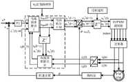
图1为本发明中大功率永磁同步电机低载波比电流PWM预测控制系统原理框图;Fig. 1 is the principle block diagram of the low carrier ratio current PWM predictive control system of high-power permanent magnet synchronous motor in the present invention;
图2为解耦电流误差积分误差补偿方法控制框图;Fig. 2 is the control block diagram of the decoupling current error integral error compensation method;
图3为永磁同步电机标量模型原理框图;Fig. 3 is the principle block diagram of the scalar model of the permanent magnet synchronous motor;
图4为d-q轴命令电压离散信号变化到连续信号的流程图;Fig. 4 is the flow chart of d-q axis command voltage discrete signal changing to continuous signal;
图5为永磁同步电机不同载波比下的电流PWM预测控制系统转速仿真波形图;Fig. 5 is the simulation waveform diagram of the rotational speed of the current PWM predictive control system under different carrier ratios of the permanent magnet synchronous motor;
图6为永磁同步电机不同载波比下的电流PWM预测控制系统定子电流d-q轴分量仿真波形图;Fig. 6 is the simulation waveform diagram of the stator current d-q axis component of the current PWM predictive control system under different carrier ratios of the permanent magnet synchronous motor;
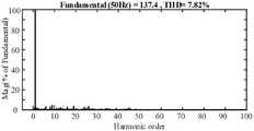
图7为永磁同步电机低载波下的电流PWM预测控制输出系统定子电流FFT谐波分析图;Fig. 7 is the stator current FFT harmonic analysis diagram of the current PWM predictive control output system under the low carrier of the permanent magnet synchronous motor;
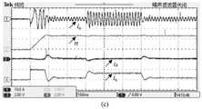
图8为永磁同步电机不同载波比下的电流PWM预测控制系统转速突变实验波形图;Fig. 8 is the experimental waveform diagram of the speed mutation experiment of the current PWM predictive control system under different carrier ratios of the permanent magnet synchronous motor;
图9为永磁同步电机不同载波比下的电流PWM预测控制系统负载突变实验波形图;Fig. 9 is the waveform diagram of the load mutation experiment of the current PWM predictive control system under different carrier ratios of the permanent magnet synchronous motor;
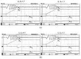
图10为永磁同步电机载波比为5时的电流PWM预测控制系统的参数敏感性分析实验图。Figure 10 is an experimental diagram of parameter sensitivity analysis of the current PWM predictive control system when the carrier ratio of the permanent magnet synchronous motor is 5.
具体实施方式Detailed ways
下面结合附图对本发明做更进一步的解释。以下实施例仅用于更加清楚地说明本发明的技术方案,而不能以此来限制本发明的保护范围。The present invention will be further explained below in conjunction with the accompanying drawings. The following examples are only used to illustrate the technical solutions of the present invention more clearly, and cannot be used to limit the protection scope of the present invention.
如图1所示,一种大功率永磁同步电机低载波比电流PWM预测控制系统,包括转速外环PI控制器、电流预测模型、反Park变换模块、SVPWM调制模块、逆变器、永磁同步电机、编码器、abc-dq坐标变换模块。具体地:As shown in Figure 1, a high-power permanent magnet synchronous motor low carrier specific current PWM predictive control system, including speed outer loop PI controller, current prediction model, inverse Park transformation module, SVPWM modulation module, inverter, permanent magnet Synchronous motor, encoder, abc-dq coordinate transformation module. specifically:
编码器用于获取永磁同步电机的转子位置角θ以及永磁同步电机的实时转速n;The encoder is used to obtain the rotor position angle θ of the permanent magnet synchronous motor and the real-time speed n of the permanent magnet synchronous motor;
转速外环PI控制器的输入量为k时刻永磁同步电机给定转速n*和实时转速n,输出量为q轴给定电流iq*(k);The input of the speed outer loop PI controller is the permanent magnet synchronous motor given speed n* and real-time speed n at time k, and the output is the q-axis given current iq* (k);
abc-dq坐标变换模块的输入量为k时刻采集永磁同步电机定子的AB相实时电流ia(k)、ib(k)以及所述永磁同步电机转子位置角θ,输出量为定子电流d-q轴分量id(k)、iq(k);The input of the abc-dq coordinate transformation module is to collect the AB-phase real-time currents ia (k), ib (k) of the permanent magnet synchronous motor stator and the rotor position angle θ of the permanent magnet synchronous motor at time k, and the output is the stator Currentdq axis components id (k), iq (k);
电流预测模型的输入量为k时刻的给定定子电流d-q轴分量id*(k)与iq*(k),以及k时刻采样电流id(k)与iq(k),输出量为使得k+2时刻采样电流idq(k+2)精确跟随电流给定idq*(k)的命令电压udq*(k+1);The input of the current prediction model is the given stator currentdq axis components id* (k) and iq* (k) at time k, and the sampled currentsid (k) and iq (k) at time k, and the output In order to make the sampled currentidq (k+2) at time k+2 precisely follow the command voltage udq* (k+1) of the given currentidq* (k);
反Park变换模块的输入量为所述d-q轴电压命令以及永磁同步电机转子位置角θ,输出量为α-β轴命令电压uαβ*(k)。The input of the inverse Park transformation module is the dq axis voltage command and the permanent magnet synchronous motor rotor position angle θ, and the output is the α-β axis command voltage uαβ* (k).
SVPWM调制模块输入量为所述α-β轴命令电压,输出量为逆变器开关控制信号;The input of the SVPWM modulation module is the command voltage of the α-β axis, and the output is the inverter switch control signal;
逆变器用于根据所述开关控制信号生成控制永磁同步电机的定子电压。The inverter is used for generating and controlling the stator voltage of the permanent magnet synchronous motor according to the switch control signal.
将id(k)、iq(k)、id*(k)、iq*(k)4个变量代入到电流预测模型中,通过电流PPC预测算法运算得到k+1时刻d-q轴命令电压udpre(k+1)、uqpre(k+1)。Substitute the four variables id (k), iq (k),id* (k), and iq* (k) into the current prediction model, and obtain thedq axis command at time k+1 through the operation of the current PPC prediction algorithm Voltage udpre (k+1), uqpre (k+1).
为了补偿系统模型误差,提高系统控制性能。如图2所示,本发明中系统中加入解耦电流误差积分补偿模块,在k时刻时,将给定定子电流d-q轴分量id*(k)、iq*(k)分别减去该时刻采样电流id(k)、iq(k),得到d-q轴定子电流误差Δid(k)、Δiq(k),使用解耦电流误差积分补偿方法得到解耦后的命令电压误差Δud(k+1)、Δuq(k+1),再经过积分调节器,得到电压命令补偿量udcom(k+1)、uqcom(k+1),最后将udpre(k+1)、uqpre(k+1)分别与udcom(k+1)、uqcom(k+1)相加,输出d-q轴命令电压ud*(k+1)、uq*(k+1)。In order to compensate the system model error and improve the system control performance. As shown in Figure 2, the decoupling current error integral compensation module is added to the system in the present invention, and at time k, the given stator currentdq axis components id* (k) and iq* (k) are respectively subtracted from the Sampling the currents id (k) and iq (k) at all times to obtain the dq-axis stator current errors Δid( k) and Δiq (k), and use the decoupling current error integral compensation method to obtain the decoupled command voltage error Δud (k+1), Δuq (k+1), and then through the integral regulator, the voltage command compensation amounts udcom (k+1), uqcom (k+1) are obtained, and finally udpre (k+1 ) and uqpre (k+1) are added to udcom (k+1) and uqcom (k+1), respectively, to output the dq axis command voltagesud* (k+1), uq* (k+1 ).
下面结合图3永磁同步电机标量模型原理图来介绍本发明中采用的电流预测模型命令电压方程的推导过程:Below in conjunction with Fig. 3 permanent magnet synchronous motor scalar model schematic diagram, the derivation process of the current prediction model command voltage equation adopted in the present invention is introduced:
由图3可得永磁同步电机电压方程:From Figure 3, the permanent magnet synchronous motor voltage equation can be obtained:

将式(1)写成电流状态方程形式:Write equation (1) in the form of the current state equation:

为了便于分析,可把式(2)写成矩阵向量形式:For the convenience of analysis, formula (2) can be written in matrix-vector form:

式中:
式(3)其实也是矩阵向量形式的微分方程,对它求解可得t∈[kTs,(k+1)Ts]的解析解为:Equation (3) is actually a differential equation in the form of a matrix vector, and the analytical solution of t∈[kTs ,(k+1)Ts ] can be obtained by solving it:

式中:微分方程的解可以分成两个部分,自由分量i1和强制分量i2;i1是控制量为零时方程的解,即零控制量作用时对应的d-q坐标系下电流值;i2代表的是非零控制量作用时对应的d-q坐标系下电流值,I是单位矩阵;u(τ)是作用到永磁同步电机侧的d-q轴定子电压矢量;In the formula: the solution of the differential equation can be divided into two parts, the free component i1 and the forced component i2 ; i1 is the solution of the equation when the control variable is zero, that is, the corresponding current value in the dq coordinate system when the zero control variable acts; i2 represents the current value in the dq coordinate system corresponding to the action of the non-zero control variable, I is the unit matrix; u(τ) is the dq-axis stator voltage vector acting on the permanent magnet synchronous motor side;
当kTs≤t<(k+1)Ts时,若忽略一个控制周期内转子的位置变化,考虑到逆变器的零阶保持器特性,可把控制量u表示为u(t)=u(kTs);若考虑转子的位置变化,则d-q轴命令电压离散信号变化到连续信号的信号流图如下图4所示;When kTs ≤t<(k+1)Ts , if the position change of the rotor in one control period is ignored, considering the zero-order keeper characteristics of the inverter, the control variable u can be expressed as u(t)= u(kTs ); if the position change of the rotor is considered, the signal flow diagram of the dq axis command voltage discrete signal changing to a continuous signal is shown in Figure 4 below;
可把图4表示为式(5):Figure 4 can be expressed as formula (5):

式中:u(t)=[ud(t)uq(t)]T,u(kTs)=[ud*(k)uq*(k)]Tud(t)、uq(t)为一个控制周期内实际作用到永磁同步电机侧的d-q轴定子电压连续量;In the formula: u(t)=[ud (t)uq (t)]T , u(kTs )=[ud* (k)uq* (k)]T ud (t), uq (t) is the continuous quantity of the dq-axis stator voltage actually acting on the permanent magnet synchronous motor side in one control cycle;
根据电流PWM预测控制原理,需要通过当前时刻的状态量来预测下一时刻的值,令当前时刻为kTs时刻,下一时刻为(k+1)Ts时刻,据此可重写式(4)如下:According to the current PWM predictive control principle, it is necessary to predict the value of the next moment through the state quantity of the current moment, let the current moment be the time kTs , and the next moment is the time (k+1)Ts , according to which the formula ( 4) as follows:

式中:
由式(6)可推导出预测模型的d-q坐标系下的标量方程,现给出简单推导过程;The scalar equation in the d-q coordinate system of the prediction model can be deduced from equation (6), and a simple derivation process is given now;
先对式(6)的方程(1)进行分析有:First, the equation (1) of equation (6) is analyzed as follows:

式中:
再对式(6)的方程(2)进行分析有:Then the equation (2) of equation (6) is analyzed as follows:

式中:
把式(7)的自由分量与式(8)的强制分量相加,就可以得到电流预测模型的标量方程,可称之为考虑转子位置的时域离散电流PPC模型,可表示成式(9):By adding the free component of equation (7) and the forced component of equation (8), the scalar equation of the current prediction model can be obtained, which can be called the time-domain discrete current PPC model considering the rotor position, which can be expressed as equation (9) ):

对式(9)加入控制延时补偿就可以得到加入延时补偿且考虑转子位置的时域离散电流PPC系统模型,这就是本文所设计大功率永磁同步电机低载波比电流PWM预测控制系统模型,如式(10)、式(11)所示:By adding control delay compensation to Equation (9), the time-domain discrete current PPC system model with delay compensation and rotor position consideration can be obtained. , as shown in formula (10) and formula (11):


式中:
为了消除系统模型误差所导致的电流静差,提出了解耦电流误差积分补偿方法;In order to eliminate the current static error caused by the system model error, a decoupling current error integral compensation method is proposed.
解耦电流误差积分补偿模块的公式为:

以上就是加入延时补偿且考虑转子位置的时域离散电流PPC模型命令电压方程的推导过程。The above is the derivation process of the command-voltage equation of the time-domain discrete current PPC model with the time-domain discrete current PPC model adding delay compensation and considering the rotor position.
为了验证本发明中的低载波比电流PWM预测控制方法能够达到本发明的发明目的,搭建了一个永磁同步电机MATLAB/simulink仿真,逆变器开关频率设置成500Hz,带额定负载起动,并在达到额定转速后(载波比为5)时变为轻载状态,仿真参数如表一所示:In order to verify that the low carrier specific current PWM predictive control method in the present invention can achieve the purpose of the present invention, a MATLAB/simulink simulation of a permanent magnet synchronous motor is built. The switching frequency of the inverter is set to 500Hz, starting with rated load, and at After reaching the rated speed (the carrier ratio is 5), it becomes a light load state, and the simulation parameters are shown in Table 1:
表一Table I
下面结合图5、图6、图7、图8来介绍上述仿真的仿真结果。The simulation results of the above simulation are described below with reference to FIG. 5 , FIG. 6 , FIG. 7 , and FIG. 8 .
图5为永磁同步电机不同载波比下的电流PWM预测控制系统转速仿真波形图。仿真结果显示采用本发明中的控制方法,无论是高载波比还是低载波比下,永磁同步电机转速能快速跟随指令并稳定,永磁同步电机转速纹波较小,且在系统突减载后仍然有较快动态响应速度,超调量也较小。Fig. 5 is the simulation waveform diagram of the rotational speed of the current PWM predictive control system under different carrier ratios of the permanent magnet synchronous motor. The simulation results show that with the control method in the present invention, no matter it is a high carrier ratio or a low carrier ratio, the speed of the permanent magnet synchronous motor can quickly follow the command and be stable, the speed ripple of the permanent magnet synchronous motor is small, and the system suddenly sheds the load. It still has a faster dynamic response speed, and the overshoot is also smaller.
图6为永磁同步电机不同载波比下的电流PWM预测控制系统定子电流d-q轴分量仿真波形图,图6(a)为定子电流q轴分量,图6(b)为定子电流d轴分量。可以观察出低载波比下q轴电流基本无静差,调节时间较短,超调量较小,有良好的动态性能,且当系统突减载依然有较高的稳定性。Figure 6 is a simulation waveform diagram of the stator current d-q-axis component of the current PWM predictive control system under different carrier ratios of the permanent magnet synchronous motor. Figure 6(a) is the q-axis component of the stator current, and Figure 6(b) is the stator current. It can be observed that the q-axis current has basically no static error under low carrier ratio, the adjustment time is short, the overshoot is small, and the dynamic performance is good, and the system still has high stability when the system is suddenly shed.
图7为永磁同步电机低载波下的电流PWM预测控制输出系统定子电流FFT谐波分析图。从图中可以看出定子电流谐波含量较少,说明定子电流畸变程度较轻,不会产生太多谐波引起较大的谐波转矩。Fig. 7 is the FFT harmonic analysis diagram of the stator current of the current PWM predictive control output system of the permanent magnet synchronous motor under the low carrier. It can be seen from the figure that the harmonic content of the stator current is less, which means that the stator current is less distorted and will not generate too many harmonics to cause a larger harmonic torque.
从仿真结果可以看出本发明所设计的大功率永磁同步电机低载波比电流PWM预测控制系统适用于大功率低载波比控制工况,可以实现永磁同步电机在此种工况下的高性能调速。It can be seen from the simulation results that the low carrier ratio current PWM predictive control system designed by the present invention is suitable for high power and low carrier ratio control conditions, and can achieve high performance of the permanent magnet synchronous motor under such conditions. Performance tuning.
为了进一步验证本发明所设计系统在大功率低载波比控制下的优越性,现基于NIcRIO-9033控制器搭建了永磁同步电机实验平台,用小功率表贴式永磁同步电机完成了低载波比下永磁同步电机调速实验。逆变器开关频率设置成500Hz,永磁同步电机参数如表二所示:In order to further verify the superiority of the system designed in the present invention under the control of high power and low carrier ratio, a permanent magnet synchronous motor experimental platform is now built based on the NIcRIO-9033 controller. Compare the speed regulation experiment of permanent magnet synchronous motor. The inverter switching frequency is set to 500Hz, and the parameters of the permanent magnet synchronous motor are shown in Table 2:
表二:Table II:
实验内容包括转速突变实验、负载突变实验、参数敏感性分析实验,如图8、图9、图10所示,实验结果与仿真结果一致,验证了算法的可行性。The experimental content includes the speed mutation experiment, the load mutation experiment, and the parameter sensitivity analysis experiment, as shown in Figure 8, Figure 9, and Figure 10. The experimental results are consistent with the simulation results, which verifies the feasibility of the algorithm.
图8为永磁同步电机调速系统转速突变实验图。从图中可以看出定子电流波形基本无畸变,定子电流谐波含量较少,转速响应非常迅速,超调量较小,且定子电流d-q轴分量电流误差能快速稳定在0附近。Figure 8 is an experimental diagram of a sudden change in the speed of the permanent magnet synchronous motor speed control system. It can be seen from the figure that the stator current waveform is basically free of distortion, the harmonic content of the stator current is small, the speed response is very fast, the overshoot is small, and the current error of the d-q axis component of the stator current can quickly stabilize around 0.
图9为永磁同步电机调速系统负载突变实验图。从图中可以看出定子电流d-q分量在给系统突加载与突减载后依然能保持较高的稳定性,且d-q轴电流波形的超调量小、调节调节时间短。Figure 9 is an experimental diagram of a sudden change in the load of the permanent magnet synchronous motor speed control system. It can be seen from the figure that the d-q component of the stator current can still maintain high stability after the system is suddenly loaded and unloaded, and the overshoot of the d-q axis current waveform is small and the adjustment time is short.
图10为永磁同步电机调速系统参数敏感性分析实验图。图10(a)为电阻失配实验波形图,图10(b)为电感失配实验波形图,图10(c)为转子磁链失配实验波形图。从图中可以看出电阻失配对系统控制性能影响较小,而电感失配与转子磁链失配相对来说对系统控制性能影响较大,但总体来说,本发明所设计的大功率永磁同步电机低载波比电流PWM预测控制系统在电机参数失配时鲁棒性较好。Figure 10 is an experimental diagram of the parameter sensitivity analysis of the permanent magnet synchronous motor speed control system. Fig. 10(a) is the waveform diagram of the resistance mismatch experiment, Fig. 10(b) is the inductance mismatch experiment waveform diagram, and Fig. 10(c) is the rotor flux linkage mismatch experiment waveform diagram. It can be seen from the figure that the resistance mismatch has little effect on the system control performance, while the inductance mismatch and rotor flux linkage mismatch have a relatively large effect on the system control performance. The low carrier specific current PWM predictive control system of the magnetic synchronous motor has better robustness when the motor parameters are mismatched.
实验结果与仿真结果一致,验证了本发明所设计的大功率永磁同步电机低载波比电流PWM预测控制系统适用于大功率低载波比控制工况,可以实现永磁同步电机在此种工况下的高性能调速。The experimental results are consistent with the simulation results, and it is verified that the low carrier ratio current PWM predictive control system of the high-power permanent magnet synchronous motor designed by the present invention is suitable for the high-power and low-carrier ratio control conditions, and can realize the permanent magnet synchronous motor in this working condition. high-performance speed control.
以上所述仅是本发明的优选实施方式,应当指出,对于本技术领域的普通技术人员来说,在不脱离本发明原理的前提下,还可以做出若干改进和润饰,这些改进和润饰也应视为本发明的保护范围。The above are only the preferred embodiments of the present invention. It should be pointed out that for those skilled in the art, without departing from the principles of the present invention, several improvements and modifications can be made. It should be regarded as the protection scope of the present invention.
Claims (8)
Translated fromChinese


Priority Applications (1)
| Application Number | Priority Date | Filing Date | Title |
|---|---|---|---|
| CN202210592622.2ACN115173755B (en) | 2022-05-27 | 2022-05-27 | Low-carrier-ratio current prediction control system and method for high-power permanent magnet synchronous motor |
Applications Claiming Priority (1)
| Application Number | Priority Date | Filing Date | Title |
|---|---|---|---|
| CN202210592622.2ACN115173755B (en) | 2022-05-27 | 2022-05-27 | Low-carrier-ratio current prediction control system and method for high-power permanent magnet synchronous motor |
Publications (2)
| Publication Number | Publication Date |
|---|---|
| CN115173755Atrue CN115173755A (en) | 2022-10-11 |
| CN115173755B CN115173755B (en) | 2025-05-02 |
Family
ID=83484360
Family Applications (1)
| Application Number | Title | Priority Date | Filing Date |
|---|---|---|---|
| CN202210592622.2AActiveCN115173755B (en) | 2022-05-27 | 2022-05-27 | Low-carrier-ratio current prediction control system and method for high-power permanent magnet synchronous motor |
Country Status (1)
| Country | Link |
|---|---|
| CN (1) | CN115173755B (en) |
Cited By (1)
| Publication number | Priority date | Publication date | Assignee | Title |
|---|---|---|---|---|
| CN118763961A (en)* | 2024-09-03 | 2024-10-11 | 深蓝汽车南京研究院有限公司 | Heating control method, device, vehicle-mounted equipment and vehicle |
Citations (4)
| Publication number | Priority date | Publication date | Assignee | Title |
|---|---|---|---|---|
| CN108768233A (en)* | 2018-06-28 | 2018-11-06 | 中车株洲电力机车有限公司 | The permanent magnet synchronous motor track with zero error system and method for discrete domain complex vector modeling |
| WO2021017237A1 (en)* | 2019-07-30 | 2021-02-04 | 中国矿业大学 | Deadbeat control system and method for permanent magnet synchronous motor under low carrier ratio |
| CN114039521A (en)* | 2021-09-15 | 2022-02-11 | 南京航空航天大学 | A low carrier ratio control method for permanent magnet synchronous motor |
| CN114094892A (en)* | 2021-09-30 | 2022-02-25 | 湖南科技大学 | Permanent magnet synchronous motor control device and method based on sliding mode observer and current prediction |
- 2022
- 2022-05-27CNCN202210592622.2Apatent/CN115173755B/enactiveActive
Patent Citations (4)
| Publication number | Priority date | Publication date | Assignee | Title |
|---|---|---|---|---|
| CN108768233A (en)* | 2018-06-28 | 2018-11-06 | 中车株洲电力机车有限公司 | The permanent magnet synchronous motor track with zero error system and method for discrete domain complex vector modeling |
| WO2021017237A1 (en)* | 2019-07-30 | 2021-02-04 | 中国矿业大学 | Deadbeat control system and method for permanent magnet synchronous motor under low carrier ratio |
| CN114039521A (en)* | 2021-09-15 | 2022-02-11 | 南京航空航天大学 | A low carrier ratio control method for permanent magnet synchronous motor |
| CN114094892A (en)* | 2021-09-30 | 2022-02-25 | 湖南科技大学 | Permanent magnet synchronous motor control device and method based on sliding mode observer and current prediction |
Cited By (1)
| Publication number | Priority date | Publication date | Assignee | Title |
|---|---|---|---|---|
| CN118763961A (en)* | 2024-09-03 | 2024-10-11 | 深蓝汽车南京研究院有限公司 | Heating control method, device, vehicle-mounted equipment and vehicle |
Also Published As
| Publication number | Publication date |
|---|---|
| CN115173755B (en) | 2025-05-02 |
Similar Documents
| Publication | Publication Date | Title |
|---|---|---|
| CN108768233B (en) | Dead-beat control system and method for PMSM based on discrete-domain complex vector modeling | |
| WO2021017237A1 (en) | Deadbeat control system and method for permanent magnet synchronous motor under low carrier ratio | |
| CN111030534B (en) | A Parameter Identification Method for Permanent Magnet Synchronous Motor in Steady-State Running Mode | |
| CN107317532B (en) | Predictive current control method and system for permanent magnet synchronous motor based on sliding mode | |
| CN209844868U (en) | Dead beat current prediction control system of permanent magnet synchronous motor | |
| CN110022105A (en) | Permanent magnet synchronous motor predictive-current control method and system based on FOSMC | |
| CN109217698B (en) | A Double Closed-loop Control Method Based on Traditional VSR Current Closed-loop Control | |
| CN109687801B (en) | Dead-beat current control method for permanent magnet synchronous linear motor | |
| CN112217437A (en) | Permanent magnet synchronous motor three-vector model prediction current control circuit and method | |
| CN111092583A (en) | A three-phase permanent magnet synchronous motor drive system current loop delay compensation method | |
| CN108054972A (en) | A kind of method for improving permanent magnetic linear synchronous motor dynamic control performance | |
| CN116073713B (en) | Model-free predictive current control method for variable vector sequence induction motor | |
| CN109525158A (en) | Compressor of air conditioner dead beat current predictive control method and system | |
| CN115955155A (en) | A robust model-free predictive control method and system for permanent magnet synchronous motors | |
| CN113437895A (en) | Matrix vector angle proportional resonance control method | |
| CN118659696A (en) | A permanent magnet drive motor parameter identification method based on double extended Kalman filter | |
| CN117375476A (en) | Three-level model-free prediction current control method for permanent magnet synchronous motor | |
| CN116111891A (en) | Synchronous speed control method, speed control device, electronic equipment, storage medium | |
| CN116191950A (en) | A new cross-axis voltage regulation and field weakening control method | |
| CN115173755A (en) | Low-carrier-ratio current prediction control system and method for high-power permanent magnet synchronous motor | |
| CN114793080A (en) | Motor parameter identification control method based on improved recursive least square method | |
| CN117997201B (en) | A DC bias hybrid excitation motor maximum torque current ratio control system and method | |
| CN116827196A (en) | Dead beat direct rotating speed control method for permanent magnet synchronous motor | |
| CN112019121B (en) | Permanent magnet synchronous motor current loop control method based on discrete extended state observer | |
| CN112019120B (en) | A Discrete Domain Current Loop Control Method for Permanent Magnet Synchronous Motors Introducing Leading-beat Current |
Legal Events
| Date | Code | Title | Description |
|---|---|---|---|
| PB01 | Publication | ||
| PB01 | Publication | ||
| SE01 | Entry into force of request for substantive examination | ||
| SE01 | Entry into force of request for substantive examination | ||
| GR01 | Patent grant | ||
| GR01 | Patent grant |