CN115164609A - Fully-sealed roller kiln waste heat utilization system - Google Patents
Fully-sealed roller kiln waste heat utilization systemDownload PDFInfo
- Publication number
- CN115164609A CN115164609ACN202211028283.1ACN202211028283ACN115164609ACN 115164609 ACN115164609 ACN 115164609ACN 202211028283 ACN202211028283 ACN 202211028283ACN 115164609 ACN115164609 ACN 115164609A
- Authority
- CN
- China
- Prior art keywords
- pipe
- pipeline
- evaporation
- furnace body
- condensation
- Prior art date
- Legal status (The legal status is an assumption and is not a legal conclusion. Google has not performed a legal analysis and makes no representation as to the accuracy of the status listed.)
- Pending
Links
- 239000002918waste heatSubstances0.000titleclaimsabstractdescription35
- 238000001704evaporationMethods0.000claimsabstractdescription59
- 230000008020evaporationEffects0.000claimsabstractdescription57
- 238000009833condensationMethods0.000claimsabstractdescription55
- 230000005494condensationEffects0.000claimsabstractdescription55
- 238000001816coolingMethods0.000claimsabstractdescription27
- 238000010438heat treatmentMethods0.000claimsabstractdescription24
- 238000004891communicationMethods0.000claimsdescription30
- 238000012546transferMethods0.000claimsdescription13
- UFWIBTONFRDIAS-UHFFFAOYSA-NNaphthaleneChemical compoundC1=CC=CC2=CC=CC=C21UFWIBTONFRDIAS-UHFFFAOYSA-N0.000claimsdescription6
- QSHDDOUJBYECFT-UHFFFAOYSA-NmercuryChemical compound[Hg]QSHDDOUJBYECFT-UHFFFAOYSA-N0.000claimsdescription3
- 229910052753mercuryInorganic materials0.000claimsdescription3
- 239000011819refractory materialSubstances0.000claimsdescription3
- WHXSMMKQMYFTQS-UHFFFAOYSA-NLithiumChemical compound[Li]WHXSMMKQMYFTQS-UHFFFAOYSA-N0.000abstractdescription8
- 229910052744lithiumInorganic materials0.000abstractdescription8
- 238000004519manufacturing processMethods0.000abstractdescription5
- 238000000034methodMethods0.000abstractdescription5
- 239000007788liquidSubstances0.000abstractdescription4
- 230000008569processEffects0.000abstractdescription3
- 239000010405anode materialSubstances0.000abstract1
- 125000004122cyclic groupChemical group0.000abstract1
- 239000002912waste gasSubstances0.000abstract1
- 230000006872improvementEffects0.000description9
- 239000007789gasSubstances0.000description6
- 239000010406cathode materialSubstances0.000description4
- 238000010586diagramMethods0.000description3
- 238000012986modificationMethods0.000description3
- 230000004048modificationEffects0.000description3
- 239000007774positive electrode materialSubstances0.000description3
- 238000005245sinteringMethods0.000description3
- PXHVJJICTQNCMI-UHFFFAOYSA-NNickelChemical compound[Ni]PXHVJJICTQNCMI-UHFFFAOYSA-N0.000description2
- QVGXLLKOCUKJST-UHFFFAOYSA-Natomic oxygenChemical compound[O]QVGXLLKOCUKJST-UHFFFAOYSA-N0.000description2
- 230000009286beneficial effectEffects0.000description2
- 150000001875compoundsChemical class0.000description2
- 238000009434installationMethods0.000description2
- 239000000463materialSubstances0.000description2
- 239000001301oxygenSubstances0.000description2
- 229910052760oxygenInorganic materials0.000description2
- 238000004064recyclingMethods0.000description2
- 230000007704transitionEffects0.000description2
- 238000010521absorption reactionMethods0.000description1
- 230000007812deficiencyEffects0.000description1
- 238000013461designMethods0.000description1
- 238000005485electric heatingMethods0.000description1
- 230000005611electricityEffects0.000description1
- 238000005265energy consumptionMethods0.000description1
- GELKBWJHTRAYNV-UHFFFAOYSA-Klithium iron phosphateChemical compound[Li+].[Fe+2].[O-]P([O-])([O-])=OGELKBWJHTRAYNV-UHFFFAOYSA-K0.000description1
- 239000007773negative electrode materialSubstances0.000description1
- 229910052759nickelInorganic materials0.000description1
Images


Classifications
- F—MECHANICAL ENGINEERING; LIGHTING; HEATING; WEAPONS; BLASTING
- F27—FURNACES; KILNS; OVENS; RETORTS
- F27D—DETAILS OR ACCESSORIES OF FURNACES, KILNS, OVENS OR RETORTS, IN SO FAR AS THEY ARE OF KINDS OCCURRING IN MORE THAN ONE KIND OF FURNACE
- F27D17/00—Arrangements for using waste heat; Arrangements for using, or disposing of, waste gases
- F27D17/10—Arrangements for using waste heat
- F—MECHANICAL ENGINEERING; LIGHTING; HEATING; WEAPONS; BLASTING
- F27—FURNACES; KILNS; OVENS; RETORTS
- F27B—FURNACES, KILNS, OVENS OR RETORTS IN GENERAL; OPEN SINTERING OR LIKE APPARATUS
- F27B9/00—Furnaces through which the charge is moved mechanically, e.g. of tunnel type; Similar furnaces in which the charge moves by gravity
- F27B9/04—Furnaces through which the charge is moved mechanically, e.g. of tunnel type; Similar furnaces in which the charge moves by gravity adapted for treating the charge in vacuum or special atmosphere
- F27B9/045—Furnaces with controlled atmosphere
- F—MECHANICAL ENGINEERING; LIGHTING; HEATING; WEAPONS; BLASTING
- F28—HEAT EXCHANGE IN GENERAL
- F28D—HEAT-EXCHANGE APPARATUS, NOT PROVIDED FOR IN ANOTHER SUBCLASS, IN WHICH THE HEAT-EXCHANGE MEDIA DO NOT COME INTO DIRECT CONTACT
- F28D15/00—Heat-exchange apparatus with the intermediate heat-transfer medium in closed tubes passing into or through the conduit walls ; Heat-exchange apparatus employing intermediate heat-transfer medium or bodies
- F28D15/02—Heat-exchange apparatus with the intermediate heat-transfer medium in closed tubes passing into or through the conduit walls ; Heat-exchange apparatus employing intermediate heat-transfer medium or bodies in which the medium condenses and evaporates, e.g. heat pipes
- F28D15/0266—Heat-exchange apparatus with the intermediate heat-transfer medium in closed tubes passing into or through the conduit walls ; Heat-exchange apparatus employing intermediate heat-transfer medium or bodies in which the medium condenses and evaporates, e.g. heat pipes with separate evaporating and condensing chambers connected by at least one conduit; Loop-type heat pipes; with multiple or common evaporating or condensing chambers
- Y—GENERAL TAGGING OF NEW TECHNOLOGICAL DEVELOPMENTS; GENERAL TAGGING OF CROSS-SECTIONAL TECHNOLOGIES SPANNING OVER SEVERAL SECTIONS OF THE IPC; TECHNICAL SUBJECTS COVERED BY FORMER USPC CROSS-REFERENCE ART COLLECTIONS [XRACs] AND DIGESTS
- Y02—TECHNOLOGIES OR APPLICATIONS FOR MITIGATION OR ADAPTATION AGAINST CLIMATE CHANGE
- Y02P—CLIMATE CHANGE MITIGATION TECHNOLOGIES IN THE PRODUCTION OR PROCESSING OF GOODS
- Y02P10/00—Technologies related to metal processing
- Y02P10/25—Process efficiency
Landscapes
- Engineering & Computer Science (AREA)
- Mechanical Engineering (AREA)
- General Engineering & Computer Science (AREA)
- Life Sciences & Earth Sciences (AREA)
- Sustainable Development (AREA)
- Physics & Mathematics (AREA)
- Thermal Sciences (AREA)
- Environmental & Geological Engineering (AREA)
- Battery Electrode And Active Subsutance (AREA)
Abstract
Description
Translated fromChinese技术领域technical field
本发明涉及烧结设备,尤其涉及一种全密封辊道窑炉余热利用系统,特别适用于生产锂电池正极材料。The invention relates to sintering equipment, in particular to a fully sealed roller kiln waste heat utilization system, which is especially suitable for producing lithium battery positive electrode materials.
背景技术Background technique
目前,辊道窑炉是锂电池正、负极材料的重要生产设备,承担了国内90%以上的生产需求,现有的辊道窑炉多采用电加热方式,耗电量巨大,如何降低辊道窑炉的能耗成为亟待解决的问题。传统的窑炉余热利用系统是把窑尾降温段的热气体通过风机引入到窑头升温段,这种方法热量利用率低,并且需安装引风机,增加了造价。更重要的是锂电池正极材料全密封辊道窑炉对烧结气氛有严格的要求,例如:高镍三元材料烧结气氛要求氧含量在95%左右,磷酸铁锂材料氧气含量小于10ppm。窑尾废气不能直接引入窑头,因此传统的余热利用系统不能应用在锂电池正极材料全密封辊道炉中。At present, the roller kiln is an important production equipment for the positive and negative electrode materials of lithium batteries, which bears more than 90% of the domestic production demand. The existing roller kilns mostly use electric heating, which consumes a lot of electricity. How to reduce the roller kiln? The energy consumption of the kiln has become an urgent problem to be solved. The traditional kiln waste heat utilization system is to introduce the hot gas from the cooling section of the kiln tail to the heating section of the kiln head through a fan. This method has a low heat utilization rate and needs to install an induced draft fan, which increases the cost. More importantly, the fully sealed roller kiln for lithium battery cathode materials has strict requirements on the sintering atmosphere. For example, the sintering atmosphere of high nickel ternary materials requires an oxygen content of about 95%, and the oxygen content of lithium iron phosphate materials is less than 10ppm. The exhaust gas from the kiln tail cannot be directly introduced into the kiln head, so the traditional waste heat utilization system cannot be applied to the fully sealed roller furnace for the cathode material of lithium batteries.
发明内容SUMMARY OF THE INVENTION
本发明要解决的技术问题是克服现有技术的不足,提供一种热量利用率高,可将余热和废气分离,能够应用于锂电池正极材料的全密封辊道窑炉预热利用系统。The technical problem to be solved by the present invention is to overcome the deficiencies of the prior art and provide a fully sealed roller kiln preheating utilization system with high heat utilization rate, which can separate waste heat and exhaust gas, and can be applied to lithium battery cathode materials.
为解决上述技术问题,本发明采用以下技术方案:In order to solve the above-mentioned technical problems, the present invention adopts the following technical solutions:
一种全密封辊道窑炉余热利用系统,包括升温段炉体和降温段炉体,所述降温段炉体上设有蒸发管道,所述升温段炉体上设有冷凝管道,所述蒸发管道和所述冷凝管道之间设有连通管道,所述蒸发管道、所述冷凝管道和所述连通管道内设有载热介质。A fully-sealed roller kiln waste heat utilization system includes a heating section furnace body and a cooling section furnace body, an evaporation pipeline is arranged on the cooling section furnace body, and a condensation pipeline is arranged on the heating section furnace body, and the evaporation pipeline is provided on the heating section furnace body. A communication pipe is arranged between the pipe and the condensation pipe, and a heat transfer medium is arranged in the evaporation pipe, the condensation pipe and the communication pipe.
作为上述技术方案的进一步改进:所述连通管道与所述冷凝管道连接的一端高于与所述蒸发管道连接的一端。As a further improvement of the above technical solution, one end of the communication pipe connected with the condensation pipe is higher than the end connected with the evaporation pipe.
作为上述技术方案的进一步改进:所述冷凝管道穿设于所述升温段炉体中,所述蒸发管道穿设于所述降温段炉体中,所述冷凝管道的两端与所述蒸发管道的两端分别通过所述连通管道对应连接。As a further improvement of the above technical solution: the condensation pipeline is penetrated in the furnace body of the heating section, the evaporation pipeline is penetrated in the furnace body of the cooling section, and the two ends of the condensation pipeline are connected to the evaporation pipeline. The two ends are respectively connected through the communication pipes correspondingly.
作为上述技术方案的进一步改进:所述冷凝管道为倒V字形管道。As a further improvement of the above technical solution: the condensation pipeline is an inverted V-shaped pipeline.
作为上述技术方案的进一步改进:所述蒸发管道和所述冷凝管道均设有上下两组,上侧的所述蒸发管道与上侧的所述冷凝管道通过一所述连通管道连接,下侧的所述蒸发管道与下侧的所述冷凝管道通过另一所述连通管道连接。As a further improvement of the above technical scheme: the evaporation pipeline and the condensation pipeline are both provided with two sets of upper and lower groups, the evaporation pipeline on the upper side and the condensation pipeline on the upper side are connected by a communication pipeline, and the evaporation pipeline on the upper side is connected with the condensation pipeline on the upper side. The evaporation duct and the condensation duct on the lower side are connected through the other communication duct.
作为上述技术方案的进一步改进:所述蒸发管道和所述冷凝管道上均设有多片换热翅片。As a further improvement of the above-mentioned technical scheme, multiple heat exchange fins are provided on both the evaporation pipe and the condensation pipe.
作为上述技术方案的进一步改进:所述连通管道位于所述升温段炉体与所述降温段炉体之间的部分包覆有阻热层。As a further improvement of the above technical solution, the part of the communication pipe between the furnace body of the heating section and the furnace body of the cooling section is covered with a heat resistance layer.
作为上述技术方案的进一步改进:所述阻热层采用耐火材料。As a further improvement of the above technical solution: the heat resistance layer adopts refractory material.
作为上述技术方案的进一步改进:所述载热介质为导热姆、萘或水银。As a further improvement of the above technical scheme: the heat transfer medium is thermal conductive compound, naphthalene or mercury.
作为上述技术方案的进一步改进:所述蒸发管道、所述冷凝管道和所述连通管道内的气压为0.005Mpa-0.02Mpa。As a further improvement of the above technical scheme: the air pressure in the evaporation pipeline, the condensation pipeline and the communication pipeline is 0.005Mpa-0.02Mpa.
与现有技术相比,本发明的优点在于:本发明公开的全密封辊道窑炉余热利用系统,在降温段炉体上设有蒸发管道,在升温段炉体上设有冷凝管道,蒸发管道和冷凝管道通过连通管道连接,各管道内注入载热介质,辊道窑炉系统生产时,蒸发管道内的载热介质在降温段炉体吸收热量转变为气态,然后通过连通管道进入冷凝管道,载热介质在冷凝管道内冷凝放热,从而为升温段炉体提供热量,实现降温段炉体余热利用,载热介质通过蒸发和冷凝两个相变过程,可以吸收和释放较大的热量,实现余热的高效率利用,且可以将余热与废气分离开,能够适用于锂电池正极材料;冷凝后的载热介质转变为液态通过连通管道回流至蒸发管道内,实现循环利用。Compared with the prior art, the advantages of the present invention are: the fully sealed roller kiln waste heat utilization system disclosed in the present invention is provided with an evaporation pipe on the furnace body in the cooling section, and a condensation pipe on the furnace body in the heating section, so that the evaporation The pipeline and the condensing pipeline are connected by the connecting pipeline, and the heating medium is injected into each pipeline. During the production of the roller kiln system, the heating medium in the evaporation pipeline absorbs heat in the cooling section and turns into a gaseous state, and then enters the condensing pipeline through the connecting pipeline. , the heat transfer medium condenses and releases heat in the condensation pipe, so as to provide heat for the furnace body in the heating section and realize the utilization of the waste heat of the furnace body in the cooling section. The heat transfer medium can absorb and release a large amount of heat through the two phase transition processes of evaporation and condensation , to achieve high-efficiency utilization of waste heat, and can separate waste heat from exhaust gas, which can be suitable for lithium battery cathode materials; the condensed heat-carrying medium is converted into a liquid state and returned to the evaporation pipeline through the communication pipeline to realize recycling.
附图说明Description of drawings
图1是本发明辊道窑炉系统的立体结构示意图。FIG. 1 is a schematic three-dimensional structure diagram of the roller kiln system of the present invention.
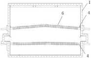
图2是本发明中的升温段炉体的横截面结构示意图。FIG. 2 is a schematic cross-sectional structure diagram of the furnace body in the heating section in the present invention.
图3是本发明中的降温段炉体的横截面结构示意图。FIG. 3 is a schematic cross-sectional structure diagram of the furnace body in the cooling section in the present invention.
图中各标号表示:1、升温段炉体;2、降温段炉体;3、蒸发管道;4、冷凝管道;5、连通管道;6、换热翅片。The symbols in the figure represent: 1. furnace body in heating section; 2. furnace body in cooling section; 3. evaporating pipeline; 4. condensing pipeline; 5. connecting pipeline; 6. heat exchange fins.
具体实施方式Detailed ways
以下结合说明书附图和具体实施例对本发明作进一步详细说明。The present invention will be further described in detail below with reference to the accompanying drawings and specific embodiments.
图1至图3示出了本发明全密封辊道窑炉余热利用系统的一种实施例,本实施例的全密封辊道窑炉余热利用系统,包括升温段炉体1和降温段炉体2,降温段炉体2上设有蒸发管道3,升温段炉体1上设有冷凝管道4,蒸发管道3和冷凝管道4之间设有连通管道5,蒸发管道3、冷凝管道4和连通管道5内装有载热介质(图中未示出,例如可以是导热姆、萘或水银等)。Figures 1 to 3 show an embodiment of the fully-sealed roller kiln waste heat utilization system of the present invention. The fully-sealed roller kiln waste heat utilization system in this embodiment includes a
本实施例的全密封辊道窑炉余热利用系统,在降温段炉体2上设有蒸发管道3,在升温段炉体1上设有冷凝管道4,蒸发管道3和冷凝管道4通过连通管道5连接,各管道内注入载热介质,辊道窑炉余热利用系统在生产时,蒸发管道3内的载热介质在降温段炉体2吸收热量转变为气体,然后通过连通管道5进入冷凝管道4,载热介质在冷凝管道4内冷凝放热,从而为升温段炉体1提供热量,实现降温段炉体2余热利用,载热介质通过蒸发和冷凝两个相变过程,可以吸收和释放较大的热量,实现余热的高效率利用,且可以将余热从废气中分离开,因此能够适用于锂电池正极材料全密封辊道炉;冷凝后的载热介质转变为液态,通过带有坡度的连通管道5回流至蒸发管道3内,实现循环利用。In the fully-sealed roller kiln waste heat utilization system of this embodiment, an
进一步地,本实施例中,连通管道5与冷凝管道4连接的一端高于与蒸发管道3连接的一端。冷凝管道4内冷凝后的液态载热介质可以利用高差回流至蒸发管道3内,无需外加动力源(例如风机、泵等),有利于简化系统结构,降低成本,同时也不会影响蒸发管道3内的气态载热介质流入冷凝管道4内。Further, in this embodiment, the end of the
进一步地,本实施例中,冷凝管道4穿设于升温段炉体1中,载热介质冷凝后有利于保持沿升温段炉体1横向方向或者说宽度方向放热均匀,且便于冷凝管道4的可靠安装,蒸发管道3穿设于降温段炉体2中,有利于充分吸收降温段炉体2横向方向或者说宽度方向的热量,且便于蒸发管道3的可靠安装,冷凝管道4的两端与蒸发管道3的两端分别通过连通管道5对应连接,整体结构对称性好,有利于保持受力的平衡性及温度的均匀性。Further, in this embodiment, the
更进一步地,本实施例中,冷凝管道4为倒V字形管道,也即冷凝管道4中部高而两端逐渐降低,相比于水平结构,有利于液态的载热介质向两端流动进入连通管道5实现回流,结构简单、可靠。冷凝管道4的V字形设计,可提高炉腔内温度均匀性,特别是对于六列宽炉膛效果更佳。Further, in this embodiment, the
作为优选的实施例,蒸发管道3和冷凝管道4均设有上下两组,上侧的蒸发管道3与上侧的冷凝管道4通过一根或多根连通管道5连接,下侧的蒸发管道3与下侧的冷凝管道4通过另一根或多根连通管道5连接。一方面,上下两组蒸发管道3内的载热介质可以充分吸收降温段炉体2的余热,从而进一步提高余热利用效率;另一方面,上下两组蒸发管道3有利于保持升温段炉体1上下两侧的温度均匀。As a preferred embodiment, both the
作为优选的实施例,蒸发管道3和冷凝管道4上均设有多片换热翅片6,换热翅片6有利于增加蒸发管道3、冷凝管道4的换热面积,从而进一步提高余热利用效率。进一步优选的,换热翅片6采用环形结构或者说环绕在蒸发管道3、冷凝管道4外周,提高圆周方向各处吸热、放热的均匀性。As a preferred embodiment, multiple
进一步地,本实施例中,连通管道5位于升温段炉体1与降温段炉体2之间的部分包覆有阻热层(图中未示出),有利于减少载热介质在连通管道5处与外界进行热量交换,有利于保证余热利用效率。Further, in this embodiment, the part of the
作为优选的实施例,阻热层采用耐火材料,使得阻热层能够适应高温环境,提高可靠性。As a preferred embodiment, the heat resistance layer is made of refractory material, so that the heat resistance layer can adapt to a high temperature environment and improve reliability.
进一步地,蒸发管道3、冷凝管道4和连通管道5内的气压为0.005Mpa-0.02Mpa,也即蒸发管道3、冷凝管道4和连通管道5内处于真空状态,防止空气残留,有利于保证系统的运行效率。本实施例中管道内的气压为0.01Mpa,当然在其他实施例中也可小范围进行调整。优选的,可在充入载热介质之后,对管道进行抽真空,使管道内压力保持在0.01Mpa左右。Further, the air pressure in the
虽然本发明已以较佳实施例揭露如上,然而并非用以限定本发明。任何熟悉本领域的技术人员,在不脱离本发明技术方案范围的情况下,都可利用上述揭示的技术内容对本发明技术方案做出许多可能的变动和修饰,或修改为等同变化的等效实施例。因此,凡是未脱离本发明技术方案的内容,依据本发明技术实质对以上实施例所做的任何简单修改、等同变化及修饰,均应落在本发明技术方案保护的范围内。Although the present invention has been disclosed above with preferred embodiments, it is not intended to limit the present invention. Any person skilled in the art, without departing from the scope of the technical solution of the present invention, can make many possible changes and modifications to the technical solution of the present invention by using the technical content disclosed above, or modify it into an equivalent implementation of equivalent changes. example. Therefore, any simple modifications, equivalent changes and modifications made to the above embodiments according to the technical essence of the present invention should fall within the protection scope of the technical solutions of the present invention without departing from the content of the technical solutions of the present invention.
Claims (10)
Translated fromChinesePriority Applications (1)
| Application Number | Priority Date | Filing Date | Title |
|---|---|---|---|
| CN202211028283.1ACN115164609A (en) | 2022-08-25 | 2022-08-25 | Fully-sealed roller kiln waste heat utilization system |
Applications Claiming Priority (1)
| Application Number | Priority Date | Filing Date | Title |
|---|---|---|---|
| CN202211028283.1ACN115164609A (en) | 2022-08-25 | 2022-08-25 | Fully-sealed roller kiln waste heat utilization system |
Publications (1)
| Publication Number | Publication Date |
|---|---|
| CN115164609Atrue CN115164609A (en) | 2022-10-11 |
Family
ID=83482119
Family Applications (1)
| Application Number | Title | Priority Date | Filing Date |
|---|---|---|---|
| CN202211028283.1APendingCN115164609A (en) | 2022-08-25 | 2022-08-25 | Fully-sealed roller kiln waste heat utilization system |
Country Status (1)
| Country | Link |
|---|---|
| CN (1) | CN115164609A (en) |
Citations (6)
| Publication number | Priority date | Publication date | Assignee | Title |
|---|---|---|---|---|
| WO2003016811A2 (en)* | 2001-08-13 | 2003-02-27 | New Qu Energy Ltd. | Device using a medium having a high heat transfer rate |
| JP2009179861A (en)* | 2008-01-31 | 2009-08-13 | Koyo Thermo System Kk | Heat treatment system |
| CN101865622A (en)* | 2010-07-13 | 2010-10-20 | 山东天力干燥设备有限公司 | Long-distance waste heat recovery system of drying tail gas |
| CN108800964A (en)* | 2018-08-01 | 2018-11-13 | 魏书明 | A kind of charcoal element can-type calcine furnace smoke temperature reducer |
| CN211041785U (en)* | 2019-10-29 | 2020-07-17 | 湖南新天力科技有限公司 | Lithium battery powder sintering full-sealed oxygen roller kiln |
| CN216592920U (en)* | 2021-10-09 | 2022-05-24 | 世源科技工程有限公司 | Energy recovery device and exhaust system |
- 2022
- 2022-08-25CNCN202211028283.1Apatent/CN115164609A/enactivePending
Patent Citations (6)
| Publication number | Priority date | Publication date | Assignee | Title |
|---|---|---|---|---|
| WO2003016811A2 (en)* | 2001-08-13 | 2003-02-27 | New Qu Energy Ltd. | Device using a medium having a high heat transfer rate |
| JP2009179861A (en)* | 2008-01-31 | 2009-08-13 | Koyo Thermo System Kk | Heat treatment system |
| CN101865622A (en)* | 2010-07-13 | 2010-10-20 | 山东天力干燥设备有限公司 | Long-distance waste heat recovery system of drying tail gas |
| CN108800964A (en)* | 2018-08-01 | 2018-11-13 | 魏书明 | A kind of charcoal element can-type calcine furnace smoke temperature reducer |
| CN211041785U (en)* | 2019-10-29 | 2020-07-17 | 湖南新天力科技有限公司 | Lithium battery powder sintering full-sealed oxygen roller kiln |
| CN216592920U (en)* | 2021-10-09 | 2022-05-24 | 世源科技工程有限公司 | Energy recovery device and exhaust system |
Similar Documents
| Publication | Publication Date | Title |
|---|---|---|
| CN111430754A (en) | A hydrogen fuel cell solid-state hydrogen storage waste heat recovery device | |
| CN106229528A (en) | A kind of fuel cell tail gas recycle device | |
| CN104916860A (en) | Outer gas flow cavity-based solid oxide fuel cell electric pile group serial connecting technology | |
| CN115164609A (en) | Fully-sealed roller kiln waste heat utilization system | |
| CN117577873A (en) | Heat pipe-phase change material coupling thermal management device applied to flow battery | |
| CN216288533U (en) | Fuel preparation device | |
| CN201599955U (en) | Multi-ventilated double heat exchange flat-plate solar collector | |
| CN212720929U (en) | Waste heat recovery system of graphitizing furnace | |
| CN201332370Y (en) | Thermo-electric generation device using vehicle exhaust pipe | |
| CN111883781B (en) | A kind of activation method of nickel salt etching graphite felt electrode | |
| CN213067131U (en) | Steel-making efficient waste heat recycling device with energy storage function | |
| CN114353351A (en) | Solar Cascade Thermal Storage System | |
| CN108613360A (en) | Air conditioner afterheat energy thermoelectricity retracting device | |
| CN203464809U (en) | Heat exchange device for high-temperature flue gas heat exchange | |
| CN104821646A (en) | Industrial waste heat recycling system using capillary pump system | |
| CN204741331U (en) | Industry waste heat recovery who uses capillary pump system utilizes system | |
| CN203010756U (en) | Hot water source absorption type heat pipe energy conservation and water conservation heating radiator | |
| CN221685203U (en) | A lightweight energy-saving furnace top cover | |
| CN220003991U (en) | Plasma reinforced electric heating methane steam reforming reactor | |
| CN220583093U (en) | Energy-saving and environment-friendly graphitizing furnace | |
| Shimei et al. | Study on feasibility of heat pipe technology for fuel cell thermal management system | |
| CN203980704U (en) | The luminous energy heat pump of secondary heat absorption type | |
| CN217685925U (en) | Solar energy step heat accumulation system | |
| CN2196286Y (en) | Heat pipe | |
| CN204118189U (en) | A kind of hydrogen fuel cell hot water utilization system |
Legal Events
| Date | Code | Title | Description |
|---|---|---|---|
| PB01 | Publication | ||
| PB01 | Publication | ||
| SE01 | Entry into force of request for substantive examination | ||
| SE01 | Entry into force of request for substantive examination |