CN115157322A - Industrial robot space pose precision testing device and method - Google Patents
Industrial robot space pose precision testing device and methodDownload PDFInfo
- Publication number
- CN115157322A CN115157322ACN202211043181.7ACN202211043181ACN115157322ACN 115157322 ACN115157322 ACN 115157322ACN 202211043181 ACN202211043181 ACN 202211043181ACN 115157322 ACN115157322 ACN 115157322A
- Authority
- CN
- China
- Prior art keywords
- coordinate system
- robot
- measurement
- pose
- point
- Prior art date
- Legal status (The legal status is an assumption and is not a legal conclusion. Google has not performed a legal analysis and makes no representation as to the accuracy of the status listed.)
- Pending
Links
Images


Classifications
- B—PERFORMING OPERATIONS; TRANSPORTING
- B25—HAND TOOLS; PORTABLE POWER-DRIVEN TOOLS; MANIPULATORS
- B25J—MANIPULATORS; CHAMBERS PROVIDED WITH MANIPULATION DEVICES
- B25J19/00—Accessories fitted to manipulators, e.g. for monitoring, for viewing; Safety devices combined with or specially adapted for use in connection with manipulators
- B25J19/0095—Means or methods for testing manipulators
Landscapes
- Engineering & Computer Science (AREA)
- Robotics (AREA)
- Mechanical Engineering (AREA)
- Manipulator (AREA)
Abstract
Translated fromChinese
Description
Translated fromChinese技术领域technical field
本发明涉及空间位姿精度测试领域,具体是一种工业机器人空间位姿精度测试装置和方法。The invention relates to the field of spatial pose accuracy testing, in particular to an industrial robot spatial pose accuracy testing device and method.
背景技术Background technique
空间位姿精度是工业机器人最重要的性能指标之一,主要包含空间位姿绝对精度与空间位姿重复精度。随着工业机器人离线编程技术的应用,机器人空间位姿绝对精度越来越重要。然而,空间位姿绝对精度的测量难度较大,一般需要使用高精度激光跟踪仪、拉线编码器测试装置或视觉传感器等进行测量。Spatial pose accuracy is one of the most important performance indicators of industrial robots, mainly including the absolute accuracy of spatial pose and the repeatability of spatial pose. With the application of off-line programming technology for industrial robots, the absolute accuracy of robot spatial pose is becoming more and more important. However, the measurement of the absolute accuracy of the spatial pose is difficult, and generally requires the use of a high-precision laser tracker, a wire-pull encoder test device, or a vision sensor for measurement.
高精度激光跟踪仪和拉线编码器测试装置的成本较高、操作较复杂,且测量姿态需要额外采购配套传感器,增加了使用成本。The high-precision laser tracker and the wire-pull encoder test device are expensive and complicated to operate, and additional sensors need to be purchased to measure the attitude, which increases the cost of use.
中国专利CN 112917510 A中使用视觉传感器测量机器人的空间位姿绝对精度,但由于一般视觉传感器的精度有限,仅能测量机器人末端的空间位姿绝对精度,无法测量空间位姿重复精度,不能完整评估机器人的精度指标。而高精度视觉传感器的成本较高,环境适应性较差。Chinese patent CN 112917510 A uses a vision sensor to measure the absolute accuracy of the spatial pose of the robot, but due to the limited accuracy of the general vision sensor, it can only measure the absolute accuracy of the spatial pose of the robot end, but cannot measure the repeatability of the spatial pose and cannot be fully evaluated. The accuracy indicator of the robot. However, high-precision vision sensors have high costs and poor environmental adaptability.
另外,中国专利CN 105865341 A和CN 109341534 A中分别提供了两种使用激光测距传感器测量机器人末端空间位姿重复精度的装置和方法,但无法测量空间位姿绝对精度,不能完整评估机器人的精度指标。In addition, Chinese patents CN 105865341 A and CN 109341534 A respectively provide two devices and methods for measuring the repeatability of the spatial pose and orientation of the robot end using a laser ranging sensor, but the absolute accuracy of the spatial pose and orientation cannot be measured, and the accuracy of the robot cannot be fully evaluated. index.
发明内容SUMMARY OF THE INVENTION
本发明为了解决现有技术的问题,提供了一种工业机器人空间位姿精度测试装置和方法,可以获取机器人基坐标系下的空间绝对位姿,结构简单,精度高,缩短了所需时间,使用方便,对测试环境适应性好。In order to solve the problems of the prior art, the present invention provides an industrial robot space pose accuracy testing device and method, which can obtain the space absolute pose under the robot base coordinate system, has a simple structure, high precision, and shortens the required time. It is easy to use and has good adaptability to the test environment.
一种工业机器人空间位姿精度测试装置,其特征在于:包括分别通过无线通讯模块与主控端连接的传感器组件和位姿测量组件;An industrial robot space position and attitude accuracy testing device, characterized in that it comprises a sensor assembly and a position and attitude measurement assembly respectively connected with a main control terminal through a wireless communication module;
所述传感器组件包括执行块、第一陀螺仪、激光测距传感器和第一无线通讯模块,执行块安装在机器人末端,跟随机器人末端运动;所述第一陀螺仪安装在执行块内部,测量执行块运动姿态;若干激光测距传感器安装在执行块周围;第一无线通讯模块安装在执行块内部,将第一陀螺仪和激光测距传感器测量的数据传输给主控端;The sensor assembly includes an execution block, a first gyroscope, a laser ranging sensor and a first wireless communication module. The execution block is installed at the end of the robot and moves with the end of the robot; the first gyroscope is installed inside the execution block and measures the execution block motion attitude; several laser ranging sensors are installed around the execution block; the first wireless communication module is installed inside the execution block, and transmits the data measured by the first gyroscope and the laser ranging sensor to the main control terminal;
所述位姿测量组件包括测量支架、接光体、第二陀螺仪和第二无线通讯模块,接光体安装在测量支架上,第二陀螺仪安装在测量支架内部用于测量其姿态,第二无线通讯模块安装在测量支架内部,将第二陀螺仪的数据传输给主控端。The position and attitude measurement assembly includes a measurement bracket, a light receiving body, a second gyroscope and a second wireless communication module. The light receiving body is installed on the measurement bracket, and the second gyroscope is installed inside the measurement bracket for measuring its attitude. The second wireless communication module is installed inside the measuring bracket, and transmits the data of the second gyroscope to the main control terminal.
进一步改进,所述若干激光测距传感器发射的激光束正交于一点。As a further improvement, the laser beams emitted by the plurality of laser ranging sensors are orthogonal to one point.
进一步改进,所述接光体为测量靶球。所述测量靶球布置位置为机器人工作空间中最大立方体的测试点。In a further improvement, the light receiving body is a measuring target ball. The arrangement position of the measurement target ball is the test point of the largest cube in the robot working space.
本发明还提供了一种工业机器人空间位姿精度测试方法,包括以下步骤:The present invention also provides a method for testing the spatial pose accuracy of an industrial robot, comprising the following steps:
1)将传感器组件的执行块安装到机器人末端,位姿测量组件放置在机器人附近的稳定平面上,并应放在传感器组件的测量区域内,位姿测量组件上的第二陀螺仪将数据通过第二无线通讯模块传递给主控端;1) Install the execution block of the sensor assembly to the end of the robot, the pose measurement assembly is placed on a stable plane near the robot, and should be placed in the measurement area of the sensor assembly, and the second gyroscope on the pose measurement assembly passes the data through. The second wireless communication module is transmitted to the main control terminal;
2)机器人带着传感器组件移动到合适位置,使得三个激光传感器发出的光照射在同一个测量靶球上,记录机器人运动参数,激光测距传感器和第一陀螺仪将数据通过第一无线通讯模块传递给主控端,求解出机器人基坐标系和测量坐标系的相对关系;2) The robot moves to a suitable position with the sensor assembly, so that the light emitted by the three laser sensors is irradiated on the same measuring target ball, and the motion parameters of the robot are recorded. The laser ranging sensor and the first gyroscope communicate the data through the first wireless communication. The module is passed to the main control terminal, and the relative relationship between the robot base coordinate system and the measurement coordinate system is solved;
3)控制机器人依次运动到剩余测量靶球位置,并重复运动直到满足测试轮数,每次运动到指定位置时,激光测距传感器和第一陀螺仪都会将数据传递给主控端,通过计算得到机器人空间位姿绝对精度与空间位姿重复精度。3) Control the robot to move to the remaining measurement target ball positions in sequence, and repeat the movement until the number of test rounds is satisfied. The absolute accuracy of the robot's spatial pose and the repeatability of the spatial pose are obtained.
进一步改进,步骤2)所述机器人基坐标系和测量坐标系的相对关系的计算过程如下:Further improvement, the calculation process of the relative relationship between the robot base coordinate system and the measurement coordinate system in step 2) is as follows:
2.1)通过三个激光传感器得到测量靶球的球心点O的实际位置;2.1) Obtain the actual position of the center point O of the measuring target ball through three laser sensors;
2.2)设坐标系V是机器人末端工具坐标系,坐标系W是位姿测量组件的测量坐标系,记点O在坐标系V中的位置为O_v,点O在坐标系W中的位置为O_w,根据坐标系变换原理,易得:2.2) Let the coordinate system V be the tool coordinate system of the robot end, the coordinate system W is the measurement coordinate system of the pose measurement component, the position of the point O in the coordinate system V is O_v, and the position of the point O in the coordinate system W is O_w , according to the principle of coordinate system transformation, it is easy to obtain:
V_org_w=O_w-R_v_w·O_v (1)V_org_w=O_w-R_v_w·O_v(1)
式中,V_org_w是坐标系V的原点在坐标系W中的位置,即机器人末端工具中心在测量坐标系中的位置;R_v_w是坐标系V至坐标系W的旋转矩阵,即机器人末端工具在测量坐标系中的姿态;In the formula, V_org_w is the position of the origin of the coordinate system V in the coordinate system W, that is, the position of the center of the robot end tool in the measurement coordinate system; R_v_w is the rotation matrix from the coordinate system V to the coordinate system W, that is, the robot end tool is measuring the pose in the coordinate system;
R_v_w=R_v_T·R_w (2)R_v_w=R_v_T·R_w (2)
式中,R_v和R_w分别是第一陀螺仪和第一陀螺仪输出的旋转矩阵,R_v_T是R_v的转置;In the formula, R_v and R_w are the rotation matrix output by the first gyroscope and the first gyroscope respectively, and R_v_T is the transpose of R_v;
每次测量后都得到机器人末端工具中心在测量坐标系中的位姿;After each measurement, the pose of the tool center of the robot end in the measurement coordinate system is obtained;
2.3)根据坐标系变换原理,得式3与式4:2.3) According to the principle of coordinate system transformation,
R_w_b=R_v_b·R_v_w_T (3)R_w_b=R_v_b·R_v_w_T (3)
式中,R_w_b是坐标系W至坐标系B的旋转矩阵,该旋转矩阵为常量;R_v_b是机器人末端工具在机器人基坐标系中的姿态,即为机器人指令姿态;R_v_w_T是R_v_w的转置,R_v_w通过式2得到;In the formula, R_w_b is the rotation matrix from the coordinate system W to the coordinate system B, and the rotation matrix is a constant; R_v_b is the attitude of the robot end tool in the robot base coordinate system, which is the robot command attitude; R_v_w_T is the transpose of R_v_w, R_v_w Obtained by
W_org_b=V_org_b-R_w_b·V_org_w (4)W_org_b=V_org_b-R_w_b·V_org_w(4)
式中,W_org_b是坐标系W的原点在坐标系B中的位置,该位置为常量;V_org_b是坐标系V的原点在坐标系B中的位置,即机器人末端工具中心在机器人基坐标系中的位置;R_w_b通过式3得到;V_org_w通过式1得到。In the formula, W_org_b is the position of the origin of the coordinate system W in the coordinate system B, which is a constant; V_org_b is the position of the origin of the coordinate system V in the coordinate system B, that is, the tool center of the robot end in the robot base coordinate system. position; R_w_b is obtained by
2.4)在同一次测试中,由于机器人基坐标系和测量坐标系的相对关系不变,易根据坐标系变换原理得到机器人末端工具中心在机器人基坐标系中的位姿[R_v_b,V_org_b],如式5、式6所示;2.4) In the same test, since the relative relationship between the robot base coordinate system and the measurement coordinate system remains unchanged, it is easy to obtain the pose [R_v_b, V_org_b] of the robot end tool center in the robot base coordinate system according to the coordinate system transformation principle, such as
R_v_b=R_w_b·R_v_w (5)R_v_b=R_w_b·R_v_w (5)
V_org_b=W_org_b+R_w_b·V_org_w (6)V_org_b=W_org_b+R_w_b·V_org_w(6)
选取位姿测量组件中心的测量靶球作为第一个被测点,求解出机器人基坐标系和测量坐标系的相对关系。The measurement target ball in the center of the pose measurement component is selected as the first measured point, and the relative relationship between the robot base coordinate system and the measurement coordinate system is solved.
步骤2.1)所述球心点O的实际位置确定方法如下:设向量FG、向量HG和向量CG为激光束方向,三条激光束方向正交于点G;点P、点Q和点R分别为三条激光束与测量靶球表面的交点,点P、点Q和点R的位置坐标通过计算执行块的尺寸与激光测距传感器测量的数据得到;已知球面上三点坐标和测量靶球的半径,计算得到测量靶球球心的位置。Step 2.1) The method for determining the actual position of the spherical center point O is as follows: let the vector FG, the vector HG and the vector CG be the directions of the laser beams, and the directions of the three laser beams are orthogonal to the point G; the point P, the point Q and the point R are respectively: The intersection of the three laser beams and the surface of the measuring target ball, the position coordinates of point P, point Q and point R are obtained by calculating the size of the execution block and the data measured by the laser ranging sensor; the coordinates of the three points on the spherical surface and the measuring target ball are known. Radius, calculated to measure the position of the center of the target ball.
本发明有益效果在于:The beneficial effects of the present invention are:
1、本发明采用激光测距传感器的特殊布置方式和配套数据处理方法,双陀螺仪的布置与同步数据处理,高精度测量靶球的设计等技术,可以获取机器人基坐标系下的空间绝对位姿,能够满足GB/T 12642-2013中提出的空间位姿绝对精度测试要求,且便于直观地观察机器人精度情况;1. The present invention adopts technologies such as the special arrangement of laser ranging sensors and the supporting data processing method, the arrangement of dual gyroscopes and synchronous data processing, the design of high-precision measurement target balls and other technologies, which can obtain the absolute spatial position of the robot in the base coordinate system. It can meet the absolute accuracy test requirements of space pose and pose proposed in GB/T 12642-2013, and it is convenient to observe the accuracy of the robot intuitively;
2、发明能够同时测量GB/T 12642-2013中的空间位姿绝对精度与空间位姿重复精度,简化了测试操作,缩短了所需时间;2. The invention can simultaneously measure the absolute accuracy of the spatial pose and the repeatability of the spatial pose in GB/T 12642-2013, which simplifies the test operation and shortens the required time;
3、本发明使用高精度激光测距传感器进行测量,精度高,成本较低;3. The present invention uses a high-precision laser ranging sensor for measurement, with high precision and low cost;
4、本发明结构简单,使用方便,对测试环境适应性好;4. The present invention has the advantages of simple structure, convenient use and good adaptability to the test environment;
5、激光测距传感器的布置方式,可以使用体积更小的接光体(测量靶球),整套测试装置的体积大大缩小,便于携带;5. The arrangement of the laser ranging sensor can use a smaller light receiver (measurement target ball), and the volume of the whole set of test devices is greatly reduced, which is easy to carry;
6、本发明的位姿测量组件上使用了陀螺仪,在测量过程中不再需要调水平操作,且可以支持不同方向摆放的测量,操作更加简便,适用面更广。6. The gyroscope is used on the position and orientation measurement component of the present invention, which no longer requires leveling operation during the measurement process, and can support measurement in different directions, with simpler operation and wider application.
附图说明Description of drawings
为了更清楚地说明本发明实施例中的技术方案,下面将对实施例中所需要使用的附图作简单地介绍,显而易见地,下面描述中的附图仅仅是本发明的一些实施例,对于本领域普通技术人员来讲,在不付出创造性劳动的前提下,还可以根据这些附图获得其它的附图。In order to illustrate the technical solutions in the embodiments of the present invention more clearly, the following briefly introduces the drawings required in the embodiments. Obviously, the drawings in the following description are only some embodiments of the present invention. For those of ordinary skill in the art, other drawings can also be obtained from these drawings without any creative effort.
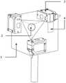
图1是传感器组件结构示意图;Figure 1 is a schematic structural diagram of a sensor assembly;
图2是位姿测量组件结构示意图;Figure 2 is a schematic structural diagram of a pose measurement assembly;
图3是实际测量时,光线和靶球相对位置示意图;Figure 3 is a schematic diagram of the relative position of the light and the target ball during actual measurement;
图4是实际测量时,工业机器人、传感器组件和位姿测量组件相对位置示意图;Figure 4 is a schematic diagram of the relative positions of the industrial robot, the sensor assembly and the pose measurement assembly during actual measurement;
图5是本发明方法流程图。Figure 5 is a flow chart of the method of the present invention.
具体实施方式Detailed ways
下面将结合本发明实施例中的附图,对本发明实施例中的技术方案进行清楚、完整地描述,显然,所描述的实施例仅仅是本发明一部分实施例,而不是全部的实施例。基于本发明中的实施例,本领域普通技术人员在没有做出创造性劳动前提下所获得的所有其它实施例,都属于本发明保护的范围。The technical solutions in the embodiments of the present invention will be clearly and completely described below with reference to the accompanying drawings in the embodiments of the present invention. Obviously, the described embodiments are only a part of the embodiments of the present invention, rather than all the embodiments. Based on the embodiments of the present invention, all other embodiments obtained by those of ordinary skill in the art without creative efforts shall fall within the protection scope of the present invention.
本发明提供一种工业机器人空间位姿精度测试系统,该系统包括传感器组件,位姿测量组件和主控端,主控端采用计算机。其中,传感器组件如图1所示,位姿测量组件如图2所示。The invention provides an industrial robot space position and attitude accuracy test system, which comprises a sensor component, a position and attitude measurement component and a main control terminal, and the main control terminal adopts a computer. Among them, the sensor component is shown in Figure 1, and the pose measurement component is shown in Figure 2.
如图1所示,传感器组件包括执行块1、陀螺仪2、激光测距传感器3和无线通讯模块4。使用时,所述执行块1安装在机器人末端,跟随机器人末端运动;所述陀螺仪2安装在执行块1内部,在执行块1运动时可以测量其姿态;共有三个激光测距传感器3安装在执行块1周围,三个激光测距传感器3发射的激光束正交于一点;所述无线通讯模块4安装在执行块1内部,将陀螺仪2和激光测距传感器3测量的数据传输给计算机。As shown in FIG. 1 , the sensor assembly includes an
如图2所示,位姿测量组件包括测量支架5、测量靶球6、陀螺仪7和无线通讯模块8。所述测量靶球6安装在测量支架5上,靶球的布置参考了GB/T12642-2013中规定的机器人工作空间中最大立方体的测试点。所述陀螺仪7安装在测量支架5内部,当测量支架5放置好后可测量其姿态;所述无线通讯模块8安装在测量支架5内部,将陀螺仪7的数据传输给计算机。As shown in FIG. 2 , the pose measurement assembly includes a
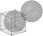
通过移动机器人末端,可以使激光测距传感器3发射的激光束都照射在同一个测量靶球6上。如图3所示,向量FG、向量HG和向量CG为激光束方向,三条激光束方向正交于点G。点O为测量靶球6的球心,点P、点Q和点R分别为三条激光束与测量靶球6表面的交点,点P、点Q和点R的位置坐标可以通过计算执行块1的尺寸与激光测距传感器3测量的数据得到。已知球面上三点(点P、点Q和点R)坐标和测量靶球6的半径,容易计算得到测量靶球6球心的位置,此时可以得到两个解(图3中的点O和点O')。而在实际情况中,如果测量靶球6的球心为点O',则激光束会被遮挡,无法照射到点P、点Q或点R,故可排除测量靶球6的球心为点O'的情况。结合激光束方向和点O与点O'的位置相对关系,可得到测量靶球6的球心点O的实际位置。By moving the end of the robot, the laser beams emitted by the
如图4所示,点O是被激光束照射的测量靶球6的球心,坐标系V是机器人末端工具坐标系,坐标系W是位姿测量组件的测量坐标系。记点O在坐标系V中的位置为O_v,O_v的值可用前述图3的说明中给出的方法得到唯一解。记点O在坐标系W中的位置为O_w,O_w的值可以在工装加工完成后通过标定测量的方式得到。根据坐标系变换原理,易得:As shown in FIG. 4 , point O is the center of the
V_org_w=O_w-R_v_w·O_v (1)V_org_w=O_w-R_v_w·O_v(1)
式1中,V_org_w是坐标系V的原点在坐标系W中的位置,即机器人末端工具中心在测量坐标系中的位置;R_v_w是坐标系V至坐标系W的旋转矩阵,即机器人末端工具在测量坐标系中的姿态,可通过陀螺仪2和陀螺仪7的数据计算得到,如式2所述。In
R_v_w=R_v_T·R_w (2)R_v_w=R_v_T·R_w (2)
式2中,R_v和R_w分别是陀螺仪2和陀螺仪7输出的旋转矩阵,R_v_T是R_v的转置。In
根据式1、式2,每次测量后都可以得到机器人末端工具中心在测量坐标系(坐标系W)中的位姿。According to
如图4所示,根据坐标系变换原理,易得式3与式4:As shown in Figure 4, according to the principle of coordinate system transformation, it is easy to obtain
R_w_b=R_v_b·R_v_w_T (3)R_w_b=R_v_b·R_v_w_T (3)
式3中,R_w_b是坐标系W至坐标系B的旋转矩阵,由于机器人基坐标系和测量坐标系的相对关系不变,在同一次测试中,该旋转矩阵为常量;R_v_b是机器人末端工具在机器人基坐标系中的姿态,即为机器人指令姿态,可通过计算机读取机器人指令位姿得到;R_v_w_T是R_v_w的转置,R_v_w通过式2得到。In
W_org_b=V_org_b-R_w_b·V_org_w (4)W_org_b=V_org_b-R_w_b·V_org_w(4)
式4中,W_org_b是坐标系W的原点在坐标系B中的位置,由于机器人基坐标系和测量坐标系的相对关系不变,在同一次测试中,该位置为常量;V_org_b是坐标系V的原点在坐标系B中的位置,即机器人末端工具中心在机器人基坐标系中的位置,可通过计算机读取机器人指令位置得到;R_w_b通过式3得到;V_org_w通过式1得到。In formula 4, W_org_b is the position of the origin of the coordinate system W in the coordinate system B. Since the relative relationship between the robot base coordinate system and the measurement coordinate system remains unchanged, in the same test, this position is constant; V_org_b is the coordinate system V The position of the origin of , in the coordinate system B, that is, the position of the robot end tool center in the robot base coordinate system, can be obtained by reading the command position of the robot by the computer; R_w_b is obtained by
在同一次测试中,由于机器人基坐标系和测量坐标系的相对关系不变,易根据坐标系变换原理得到机器人末端工具中心在机器人基坐标系中的位姿[R_v_b,V_org_b],如式5、式6所示。In the same test, since the relative relationship between the robot base coordinate system and the measurement coordinate system remains unchanged, it is easy to obtain the pose [R_v_b, V_org_b] of the robot end tool center in the robot base coordinate system according to the principle of coordinate system transformation, as shown in
R_v_b=R_w_b·R_v_w (5)R_v_b=R_w_b·R_v_w (5)
V_org_b=W_org_b+R_w_b·V_org_w (6)V_org_b=W_org_b+R_w_b·V_org_w(6)
一般地,可以选取位姿测量组件中心的测量靶球6作为第一个被测点,求解出机器人基坐标系和测量坐标系的相对关系。Generally, the
根据上述方法,每次测量都可以计算得到机器人末端工具中心在机器人基坐标系(坐标系B)中的位置和姿态信息。按照同样的方法测量至满足测量次数,同时记录机器人指令位姿,再通过计算机处理,按照标准GB/T 12642中7.2章节规定的方法计算,即可得到机器人空间位姿绝对精度与空间位姿重复精度。According to the above method, the position and attitude information of the tool center of the robot end in the robot base coordinate system (coordinate system B) can be calculated for each measurement. Measure in the same way until the number of measurements is met, record the robot's command pose, and then process it through computer and calculate it according to the method specified in Chapter 7.2 of the standard GB/T 12642, and then the absolute accuracy of the robot's spatial pose and the repetition of the spatial pose can be obtained. precision.
如图5所示,一种工业机器人空间位姿精度测试方法,包括如下步骤:As shown in Figure 5, a method for testing the spatial pose accuracy of an industrial robot includes the following steps:
1)将传感器组件的执行块1安装到机器人末端,位姿测量组件放置在机器人附近的稳定平面上,并应放在传感器组件的测量区域内,位姿测量组件上的陀螺仪7会将数据通过无线通讯模块8传递给计算机;1) Install the
2)机器人带着传感器组件移动到合适位置,使得三个激光传感器3发出的光照射在同一个测量靶球6上,记录机器人运动参数,激光测距传感器3和陀螺仪2将数据通过无线通讯模块4传递给计算机;2) The robot moves to a suitable position with the sensor assembly, so that the light emitted by the three
3)依次控制机器人依次运动到剩余四个测量靶球6位置,并重复运动直到满足测试轮数,每次运动到指定位置时,激光测距传感器3和陀螺仪2都会将数据传递给计算机;3) Control the robot to move to the remaining four measuring
4)采用具体实施方式中提供的算法,利用计算机中对数据进行计算,得到位姿绝对精度和位姿重复精度。4) The algorithm provided in the specific embodiment is adopted, and the data is calculated in the computer to obtain the absolute accuracy of the pose and the repetition accuracy of the pose.
本说明书中的各个实施例均采用递进的方式描述,各个实施例之间相同相似的部分互相参见即可,每个实施例重点说明的都是与其他实施例的不同之处。尤其,对于设备实施例而言,以上所述仅是本发明的优选实施方式,由于其基本相似于方法实施例,所以描述得比较简单,相关之处参见方法实施例的部分说明即可。以上所述,仅为本发明的具体实施方式,但本发明的保护范围并不局限于此,任何熟悉本技术领域的技术人员在本发明揭露的技术范围内,对于本技术领域的普通技术人员来说,可轻易想到的变化或替换,在不脱离本发明原理的前提下,都应涵盖在本发明的保护范围之内。因此,本发明的保护范围应该以权利要求的保护范围为准。Each embodiment in this specification is described in a progressive manner, and the same and similar parts between the various embodiments may be referred to each other, and each embodiment focuses on the differences from other embodiments. In particular, for the device embodiments, the above descriptions are only preferred implementations of the present invention. Since they are basically similar to the method embodiments, the description is relatively simple. For relevant details, please refer to the partial descriptions of the method embodiments. The above are only specific embodiments of the present invention, but the protection scope of the present invention is not limited thereto. In other words, any easily conceivable changes or substitutions should be included within the protection scope of the present invention without departing from the principles of the present invention. Therefore, the protection scope of the present invention should be subject to the protection scope of the claims.
Claims (7)
Priority Applications (1)
| Application Number | Priority Date | Filing Date | Title |
|---|---|---|---|
| CN202211043181.7ACN115157322A (en) | 2022-08-29 | 2022-08-29 | Industrial robot space pose precision testing device and method |
Applications Claiming Priority (1)
| Application Number | Priority Date | Filing Date | Title |
|---|---|---|---|
| CN202211043181.7ACN115157322A (en) | 2022-08-29 | 2022-08-29 | Industrial robot space pose precision testing device and method |
Publications (1)
| Publication Number | Publication Date |
|---|---|
| CN115157322Atrue CN115157322A (en) | 2022-10-11 |
Family
ID=83481108
Family Applications (1)
| Application Number | Title | Priority Date | Filing Date |
|---|---|---|---|
| CN202211043181.7APendingCN115157322A (en) | 2022-08-29 | 2022-08-29 | Industrial robot space pose precision testing device and method |
Country Status (1)
| Country | Link |
|---|---|
| CN (1) | CN115157322A (en) |
Cited By (3)
| Publication number | Priority date | Publication date | Assignee | Title |
|---|---|---|---|---|
| CN116117869A (en)* | 2023-02-02 | 2023-05-16 | 广东建石科技有限公司 | Method, device and system for testing position accuracy of robot |
| CN118081776A (en)* | 2024-04-25 | 2024-05-28 | 中国科学院长春光学精密机械与物理研究所 | Robot TCP point calibration method, device, medium and equipment of multipath sensor |
| CN119458321A (en)* | 2024-11-05 | 2025-02-18 | 上海智元新创技术有限公司 | Robot control method, robot and electronic equipment |
Citations (15)
| Publication number | Priority date | Publication date | Assignee | Title |
|---|---|---|---|---|
| US5528505A (en)* | 1993-09-20 | 1996-06-18 | Romer | Position-marking method for a machine that measures in three dimensions, and apparatus for implementing the method |
| JP2002310641A (en)* | 2001-04-19 | 2002-10-23 | Kanto Auto Works Ltd | Coordinate system calibrating method for three- dimensional shape measuring instrument |
| JP2005283600A (en)* | 2005-06-13 | 2005-10-13 | Kawasaki Heavy Ind Ltd | Position and orientation detection device for movable body |
| CN101660904A (en)* | 2009-09-22 | 2010-03-03 | 大连海事大学 | Kinematics calibration method of measurement robot |
| CN105157697A (en)* | 2015-07-31 | 2015-12-16 | 天津大学 | Indoor mobile robot pose measurement system and measurement method based on optoelectronic scanning |
| JP2016057151A (en)* | 2014-09-09 | 2016-04-21 | 新日本工機株式会社 | Three-dimensional shape measurement system |
| CN105865341A (en)* | 2016-05-28 | 2016-08-17 | 上海大学 | Device and method for measuring repeated positioning accuracy of industrial robot spatial poses |
| CN106959080A (en)* | 2017-04-10 | 2017-07-18 | 上海交通大学 | A kind of large complicated carved components three-dimensional pattern optical measuring system and method |
| CN109176517A (en)* | 2018-09-10 | 2019-01-11 | 武汉久同智能科技有限公司 | Series connection industrial robot link parameters scaling method based on the constraint of end name point |
| US20190022867A1 (en)* | 2016-03-22 | 2019-01-24 | Tyco Electronics (Shanghai) Co. Ltd. | Automatic Calibration Method For Robot System |
| CN110355788A (en)* | 2019-07-24 | 2019-10-22 | 哈尔滨工业大学(深圳) | Moving operation machine National People's Congress scale space high-precision on-line proving system |
| CN110871434A (en)* | 2019-11-25 | 2020-03-10 | 清华大学 | A kinematics calibration method for parallel processing equipment |
| US20200206945A1 (en)* | 2018-12-29 | 2020-07-02 | Ubtech Robotics Corp Ltd | Robot pose estimation method and apparatus and robot using the same |
| CN111660295A (en)* | 2020-05-28 | 2020-09-15 | 中国科学院宁波材料技术与工程研究所 | Industrial robot absolute precision calibration system and calibration method |
| US20220212349A1 (en)* | 2021-01-07 | 2022-07-07 | Ford Global Technologies, Llc | Method and system for determining sensor placement for a workspace based on robot pose scenarios |
- 2022
- 2022-08-29CNCN202211043181.7Apatent/CN115157322A/enactivePending
Patent Citations (15)
| Publication number | Priority date | Publication date | Assignee | Title |
|---|---|---|---|---|
| US5528505A (en)* | 1993-09-20 | 1996-06-18 | Romer | Position-marking method for a machine that measures in three dimensions, and apparatus for implementing the method |
| JP2002310641A (en)* | 2001-04-19 | 2002-10-23 | Kanto Auto Works Ltd | Coordinate system calibrating method for three- dimensional shape measuring instrument |
| JP2005283600A (en)* | 2005-06-13 | 2005-10-13 | Kawasaki Heavy Ind Ltd | Position and orientation detection device for movable body |
| CN101660904A (en)* | 2009-09-22 | 2010-03-03 | 大连海事大学 | Kinematics calibration method of measurement robot |
| JP2016057151A (en)* | 2014-09-09 | 2016-04-21 | 新日本工機株式会社 | Three-dimensional shape measurement system |
| CN105157697A (en)* | 2015-07-31 | 2015-12-16 | 天津大学 | Indoor mobile robot pose measurement system and measurement method based on optoelectronic scanning |
| US20190022867A1 (en)* | 2016-03-22 | 2019-01-24 | Tyco Electronics (Shanghai) Co. Ltd. | Automatic Calibration Method For Robot System |
| CN105865341A (en)* | 2016-05-28 | 2016-08-17 | 上海大学 | Device and method for measuring repeated positioning accuracy of industrial robot spatial poses |
| CN106959080A (en)* | 2017-04-10 | 2017-07-18 | 上海交通大学 | A kind of large complicated carved components three-dimensional pattern optical measuring system and method |
| CN109176517A (en)* | 2018-09-10 | 2019-01-11 | 武汉久同智能科技有限公司 | Series connection industrial robot link parameters scaling method based on the constraint of end name point |
| US20200206945A1 (en)* | 2018-12-29 | 2020-07-02 | Ubtech Robotics Corp Ltd | Robot pose estimation method and apparatus and robot using the same |
| CN110355788A (en)* | 2019-07-24 | 2019-10-22 | 哈尔滨工业大学(深圳) | Moving operation machine National People's Congress scale space high-precision on-line proving system |
| CN110871434A (en)* | 2019-11-25 | 2020-03-10 | 清华大学 | A kinematics calibration method for parallel processing equipment |
| CN111660295A (en)* | 2020-05-28 | 2020-09-15 | 中国科学院宁波材料技术与工程研究所 | Industrial robot absolute precision calibration system and calibration method |
| US20220212349A1 (en)* | 2021-01-07 | 2022-07-07 | Ford Global Technologies, Llc | Method and system for determining sensor placement for a workspace based on robot pose scenarios |
Non-Patent Citations (1)
| Title |
|---|
| 史晓佳;张福民;曲兴华;刘柏灵;王俊龙;: "KUKA工业机器人位姿测量与在线误差补偿", 机械工程学报, no. 08, 30 April 2017 (2017-04-30), pages 1 - 7* |
Cited By (5)
| Publication number | Priority date | Publication date | Assignee | Title |
|---|---|---|---|---|
| CN116117869A (en)* | 2023-02-02 | 2023-05-16 | 广东建石科技有限公司 | Method, device and system for testing position accuracy of robot |
| CN116117869B (en)* | 2023-02-02 | 2023-08-15 | 广东建石科技有限公司 | Method, device and system for testing position accuracy of robot |
| CN118081776A (en)* | 2024-04-25 | 2024-05-28 | 中国科学院长春光学精密机械与物理研究所 | Robot TCP point calibration method, device, medium and equipment of multipath sensor |
| CN118081776B (en)* | 2024-04-25 | 2024-07-26 | 中国科学院长春光学精密机械与物理研究所 | Method, device, medium and equipment for calibrating TCP points of robot with multi-channel sensors |
| CN119458321A (en)* | 2024-11-05 | 2025-02-18 | 上海智元新创技术有限公司 | Robot control method, robot and electronic equipment |
Similar Documents
| Publication | Publication Date | Title |
|---|---|---|
| CN115157322A (en) | Industrial robot space pose precision testing device and method | |
| CN107042528B (en) | Kinematics calibration system and method for industrial robot | |
| CN110695993B (en) | Synchronous measurement method, system and device for flexible mechanical arm | |
| EP2350562B1 (en) | Positioning interface for spatial query | |
| CN102607457B (en) | Measuring device and measuring method for large three-dimensional morphology based on inertial navigation technology | |
| CN100390503C (en) | Laser Tracking Inertial Combined Measurement System and Its Measurement Method | |
| RU2466858C1 (en) | Method of control of accuracy of profiled movements of industry robots | |
| CN105865341B (en) | Industrial robot spatial pose repetitive positioning accuracy measuring device and method | |
| CN102654387B (en) | Online industrial robot calibration device based on spatial curved surface restraint | |
| CN105058387A (en) | Industrial robot base coordinate system calibration method based on laser tracker | |
| CN102374847A (en) | Work space six degree-of-freedom posture dynamic measurement equipment and method | |
| CN103528519B (en) | A kind of measurement scaling method of some projection optics gauge head spatial position vector | |
| CN112729345B (en) | Method and device for detecting precision of optical positioner | |
| CN109238199B (en) | Robot rotating shaft kinematic parameter calibration method | |
| CN111595238A (en) | Laser tracker precision field evaluation system based on multi-station method | |
| CN110672049A (en) | Method and system for determining the relation between a robot coordinate system and a workpiece coordinate system | |
| CN111256592B (en) | External parameter calibration device and method for structured light sensor | |
| CN105180940B (en) | A kind of determination method of the indoor objects astronomic coordinate based on wMPS systems | |
| CN114234877A (en) | Displacement sensor vector calibration method for R-test instrument | |
| CN116867615A (en) | Installation position measuring device, installation position measuring method, robot control device, teaching system, and simulation device for robot | |
| CN113276115A (en) | Hand-eye calibration method and device without robot movement | |
| CN102445172A (en) | Method for measuring position relation of space object | |
| CN113878586B (en) | Robot kinematics calibration device, method and system | |
| CN115388911A (en) | Precision measurement method and device of optical motion capture system and electronic equipment | |
| CN107588929A (en) | Ball-screen projection/tracking system scaling method and calibration device |
Legal Events
| Date | Code | Title | Description |
|---|---|---|---|
| PB01 | Publication | ||
| PB01 | Publication | ||
| SE01 | Entry into force of request for substantive examination | ||
| SE01 | Entry into force of request for substantive examination |