CN115153962A - A transcatheter valve replacement device and its stent - Google Patents
A transcatheter valve replacement device and its stentDownload PDFInfo
- Publication number
- CN115153962A CN115153962ACN202210772820.7ACN202210772820ACN115153962ACN 115153962 ACN115153962 ACN 115153962ACN 202210772820 ACN202210772820 ACN 202210772820ACN 115153962 ACN115153962 ACN 115153962A
- Authority
- CN
- China
- Prior art keywords
- stent body
- stent
- skirt
- replacement valve
- anchoring
- Prior art date
- Legal status (The legal status is an assumption and is not a legal conclusion. Google has not performed a legal analysis and makes no representation as to the accuracy of the status listed.)
- Pending
Links
Images


Classifications
- A—HUMAN NECESSITIES
- A61—MEDICAL OR VETERINARY SCIENCE; HYGIENE
- A61F—FILTERS IMPLANTABLE INTO BLOOD VESSELS; PROSTHESES; DEVICES PROVIDING PATENCY TO, OR PREVENTING COLLAPSING OF, TUBULAR STRUCTURES OF THE BODY, e.g. STENTS; ORTHOPAEDIC, NURSING OR CONTRACEPTIVE DEVICES; FOMENTATION; TREATMENT OR PROTECTION OF EYES OR EARS; BANDAGES, DRESSINGS OR ABSORBENT PADS; FIRST-AID KITS
- A61F2/00—Filters implantable into blood vessels; Prostheses, i.e. artificial substitutes or replacements for parts of the body; Appliances for connecting them with the body; Devices providing patency to, or preventing collapsing of, tubular structures of the body, e.g. stents
- A61F2/02—Prostheses implantable into the body
- A61F2/24—Heart valves ; Vascular valves, e.g. venous valves; Heart implants, e.g. passive devices for improving the function of the native valve or the heart muscle; Transmyocardial revascularisation [TMR] devices; Valves implantable in the body
- A61F2/2427—Devices for manipulating or deploying heart valves during implantation
- A—HUMAN NECESSITIES
- A61—MEDICAL OR VETERINARY SCIENCE; HYGIENE
- A61F—FILTERS IMPLANTABLE INTO BLOOD VESSELS; PROSTHESES; DEVICES PROVIDING PATENCY TO, OR PREVENTING COLLAPSING OF, TUBULAR STRUCTURES OF THE BODY, e.g. STENTS; ORTHOPAEDIC, NURSING OR CONTRACEPTIVE DEVICES; FOMENTATION; TREATMENT OR PROTECTION OF EYES OR EARS; BANDAGES, DRESSINGS OR ABSORBENT PADS; FIRST-AID KITS
- A61F2/00—Filters implantable into blood vessels; Prostheses, i.e. artificial substitutes or replacements for parts of the body; Appliances for connecting them with the body; Devices providing patency to, or preventing collapsing of, tubular structures of the body, e.g. stents
- A61F2/02—Prostheses implantable into the body
- A61F2/24—Heart valves ; Vascular valves, e.g. venous valves; Heart implants, e.g. passive devices for improving the function of the native valve or the heart muscle; Transmyocardial revascularisation [TMR] devices; Valves implantable in the body
- A61F2/2412—Heart valves ; Vascular valves, e.g. venous valves; Heart implants, e.g. passive devices for improving the function of the native valve or the heart muscle; Transmyocardial revascularisation [TMR] devices; Valves implantable in the body with soft flexible valve members, e.g. tissue valves shaped like natural valves
- A61F2/2418—Scaffolds therefor, e.g. support stents
- A—HUMAN NECESSITIES
- A61—MEDICAL OR VETERINARY SCIENCE; HYGIENE
- A61F—FILTERS IMPLANTABLE INTO BLOOD VESSELS; PROSTHESES; DEVICES PROVIDING PATENCY TO, OR PREVENTING COLLAPSING OF, TUBULAR STRUCTURES OF THE BODY, e.g. STENTS; ORTHOPAEDIC, NURSING OR CONTRACEPTIVE DEVICES; FOMENTATION; TREATMENT OR PROTECTION OF EYES OR EARS; BANDAGES, DRESSINGS OR ABSORBENT PADS; FIRST-AID KITS
- A61F2220/00—Fixations or connections for prostheses classified in groups A61F2/00 - A61F2/26 or A61F2/82 or A61F9/00 or A61F11/00 or subgroups thereof
- A61F2220/0008—Fixation appliances for connecting prostheses to the body
- A61F2220/0016—Fixation appliances for connecting prostheses to the body with sharp anchoring protrusions, e.g. barbs, pins, spikes
Landscapes
- Health & Medical Sciences (AREA)
- Cardiology (AREA)
- Engineering & Computer Science (AREA)
- Biomedical Technology (AREA)
- Heart & Thoracic Surgery (AREA)
- Transplantation (AREA)
- Oral & Maxillofacial Surgery (AREA)
- Vascular Medicine (AREA)
- Life Sciences & Earth Sciences (AREA)
- Animal Behavior & Ethology (AREA)
- General Health & Medical Sciences (AREA)
- Public Health (AREA)
- Veterinary Medicine (AREA)
- Prostheses (AREA)
Abstract
Translated fromChinese
Description
Translated fromChinese技术领域technical field
本发明涉及心脏瓣膜技术领域,具体涉及一种经导管置换瓣膜装置及支架。The invention relates to the technical field of heart valves, in particular to a transcatheter replacement valve device and a stent.
背景技术Background technique
经导管二尖瓣置换术(TMVR)无需开胸、无需心脏停跳、无需体外循环,大大降低了手术创伤,成为继经导管主动脉瓣置换术(TAVR)之后的又一个研究热点。现有经导管二尖瓣置换系统大多数是依靠径向支撑力锚定或夹取人工瓣膜,通过多个锚定件提供径向支撑力从而锚定在主动脉瓣或二尖瓣处,但容易出现锚定力不足,锚定件偏移,导致人工瓣膜移位,无法保证人工瓣环与自体瓣环的同轴度,从而导致瓣周漏或引发其他并发症。因此,需要提供一种能够锚固稳定的经导管置换瓣膜装置。Transcatheter mitral valve replacement (TMVR) does not require thoracotomy, cardiac arrest, and cardiopulmonary bypass, which greatly reduces the surgical trauma and becomes another research hotspot after transcatheter aortic valve replacement (TAVR). Most of the existing transcatheter mitral valve replacement systems rely on radial support force to anchor or clip the artificial valve, and provide radial support force through multiple anchors to anchor at the aortic valve or mitral valve. Insufficient anchoring force is prone to occur, and the anchoring piece is displaced, resulting in the displacement of the artificial valve, and the coaxiality of the artificial valve annulus and the native valve annulus cannot be guaranteed, resulting in paravalvular leakage or other complications. Therefore, there is a need to provide a transcatheter replacement valve device that can be anchored and stabilized.
发明内容SUMMARY OF THE INVENTION
因此,本发明要解决的技术问题在于克服现有技术中的锚定件损伤心肌,锚定件周向不稳定导致偏移及锚定力不足导致人工瓣膜移位的缺陷,从而提供一种经导管置换瓣膜装置及支架。Therefore, the technical problem to be solved by the present invention is to overcome the defects in the prior art that the anchoring member damages the myocardium, the circumferential instability of the anchoring member causes offset and the insufficient anchoring force causes the artificial valve to shift, so as to provide a Catheter replacement valve devices and stents.
为了解决上述问题,本发明一方面提供了一种经导管置换瓣膜支架,包括支架主体和锚定结构。其中,支架主体为可径向压缩和展开的筒型框架结构,具有压握状态和展开状态;锚定结构为围绕支架主体的外周设置的封闭的框架结构;在支架主体处于展开状态下,锚定结构朝向支架主体的外侧扩展,以使支架主体锚定。In order to solve the above problems, one aspect of the present invention provides a transcatheter replacement valve stent, which includes a stent body and an anchoring structure. Wherein, the stent body is a radially compressible and expandable cylindrical frame structure with a crimped state and an expanded state; the anchoring structure is a closed frame structure arranged around the periphery of the stent body; when the stent body is in the expanded state, the anchor The anchoring structure expands toward the outside of the stent body to anchor the stent body.
可选的,锚定结构包括多个锚定件,锚定件围绕支架主体外周设置,锚定件具有至少两个连接部,锚定件通过连接部与支架主体连接,相邻的两个连接部之间通过支撑部连接;在支架主体处于展开状态下,支撑部朝向支架主体的外侧扩展,以使支架主体锚定。Optionally, the anchoring structure includes a plurality of anchoring parts, the anchoring parts are arranged around the outer circumference of the stent body, the anchoring part has at least two connecting parts, the anchoring parts are connected with the stent body through the connecting parts, and two adjacent connecting parts are connected. The parts are connected by a support part; when the stent body is in the unfolded state, the support part expands toward the outside of the stent body to anchor the stent body.
可选的,支撑部具有折弯结构。Optionally, the support portion has a bending structure.
可选的,折弯结构的外轮廓为圆滑的曲线。Optionally, the outer contour of the bending structure is a smooth curve.
可选的,锚定件具有第一连接部和第二连接部,折弯结构包括与第一连接部连接的第一折弯段,以及与第二连接部连接的第二折弯段,第一折弯段和第二折弯段之间具有相对扭转角,使锚定结构形成螺旋状封闭的框架结构。Optionally, the anchor has a first connecting part and a second connecting part, the bending structure includes a first bending section connected with the first connecting part, and a second bending section connected with the second connecting part, the first bending section There is a relative twist angle between the first bending section and the second bending section, so that the anchoring structure forms a helical closed frame structure.
可选的,第一折弯段和第二折弯段的相对扭转角为45°~135°。Optionally, the relative twist angle of the first bending section and the second bending section is 45°˜135°.
可选的,第一折弯段和第二折弯段的相对扭转角为90°。Optionally, the relative twist angle of the first bending segment and the second bending segment is 90°.
可选的,锚定件包括锚定杆,锚定杆的两端为连接部,锚定杆中部折弯构成支撑部,锚定杆的连接部与支架主体的第一端连接,在支架主体处于展开状态下,锚定杆的支撑部朝向支架主体的第二端延伸。Optionally, the anchoring member includes an anchoring rod, two ends of the anchoring rod are connecting parts, the middle part of the anchoring rod is bent to form a supporting part, and the connecting part of the anchoring rod is connected with the first end of the bracket main body, and the supporting part is formed in the bracket main body. In the deployed state, the support portion of the anchor rod extends toward the second end of the stent body.
可选的,锚定结构与支架主体的第一端连接,支架主体处于压握状态下,锚定结构在支架主体的径向上不与支架主体重叠。Optionally, the anchoring structure is connected to the first end of the stent body, the stent body is in a crimped state, and the anchoring structure does not overlap the stent body in the radial direction of the stent body.
可选的,还包括裙撑结构,裙撑结构设于支架主体上,裙撑结构环绕支架主体一周并朝向支架主体的外侧扩展,在支架主体处于展开状态下,裙撑结构和锚定结构构成夹持机构,夹持机构适于夹持自体瓣叶。Optionally, it also includes a skirt support structure. The skirt support structure is provided on the bracket body. The skirt support structure surrounds the bracket body and expands toward the outside of the bracket body. When the bracket body is in the unfolded state, the skirt support structure and the anchoring structure constitute The clamping mechanism is suitable for clamping the autologous valve leaflet.
可选的,裙撑结构包括与支架主体连接的第一裙撑段以及与第一裙撑段连接的第二裙撑段,第一裙撑段向外弯曲设置,第二裙撑段向内弯曲设置。Optionally, the skirt support structure includes a first skirt support section connected with the bracket body and a second skirt support section connected with the first skirt support section, the first skirt support section is bent outward, and the second skirt support section is arranged inward. Bend settings.
可选的,支撑部与裙撑结构的第二裙撑段配合,适于夹持自体瓣叶。Optionally, the support part is matched with the second skirt segment of the skirt structure and is suitable for clamping the autologous valve leaflet.
可选的,相邻的两个锚定件之间连接有加强结构。Optionally, a reinforcing structure is connected between two adjacent anchors.
可选的,加强结构包括加强杆,加强杆为V型、U型、W型中的一个或多个的组合,加强杆的两端分别与相邻的两个锚定件连接。Optionally, the reinforcement structure includes reinforcement rods, the reinforcement rods are a combination of one or more of V-shaped, U-shaped, and W-shaped, and two ends of the reinforcement rods are respectively connected to two adjacent anchors.
可选的,支架主体的第二端设有输送连接结构,输送连接结构包括围绕支架主体一周设置的多个连接杆,连接杆的一端与支架主体的第二端连接,连接杆的另一端沿支架主体的轴向远离支架主体的第二端延伸,并在端部设置挂接部,挂接部适于与输送系统连接。Optionally, the second end of the stent body is provided with a transport connection structure, the transport link structure includes a plurality of connecting rods arranged around the circumference of the stent body, one end of the connecting rods is connected with the second end of the stent body, and the other end of the connecting rods runs along the circumference of the stent body. The axial direction of the stent body extends away from the second end of the stent body, and a hook portion is provided at the end portion, and the hook portion is suitable for connecting with the delivery system.
可选的,支架主体围绕支架主体一周设有多个瓣叶缝合耳。Optionally, the stent body is provided with a plurality of leaflet suture ears around the circumference of the stent body.
本发明的另一方面提供了一种经导管置换瓣膜装置,包括以上技术方案中任一项的经导管置换瓣膜支架。Another aspect of the present invention provides a transcatheter valve replacement device, including the transcatheter valve replacement stent according to any one of the above technical solutions.
可选的,经导管置换瓣膜支架包括裙撑结构,裙撑结构上连接有密封裙布,密封裙布围绕支架主体一圈贴合地设于支架主体的内侧,密封裙布的第一端与裙撑结构连接,密封裙布的第二端朝向支架主体的第一端延伸。Optionally, the transcatheter replacement valve stent includes a skirt support structure, the skirt support structure is connected with a sealing skirt, the sealing skirt is fitted around the main body of the bracket and is fitted on the inner side of the main body of the bracket, and the first end of the sealing skirt is connected to the inner side of the main body of the bracket. The skirt structure is connected, and the second end of the sealing skirt extends toward the first end of the stent body.
可选的,经导管置换瓣膜支架还包括瓣叶缝合耳,密封裙布的第二端部分或完全覆盖瓣叶缝合耳。Optionally, the transcatheter replacement valve stent further includes leaflet suture ears, and the second end of the sealing skirt partially or completely covers the valve leaflet suture ears.
可选的,经导管置换瓣膜支架还包括瓣叶缝合耳,支架主体的内侧通过瓣叶缝合耳缝合连接有人工瓣膜;人工瓣膜设有两片,适于置换患者的二尖瓣;或,人工瓣膜设有三片,适于置换患者的主动脉瓣;在一些特殊的医疗状况下,人工瓣膜也可以设置四片。Optionally, the transcatheter replacement valve stent also includes valve leaflet suture ears, and the inner side of the stent body is sutured and connected with an artificial valve through the valve leaflet suture ears; the artificial valve is provided with two pieces, which are suitable for replacing the patient's mitral valve; The valve is provided with three pieces, suitable for replacing the patient's aortic valve; in some special medical conditions, the artificial valve can also be set with four pieces.
本发明具有以下优点:The present invention has the following advantages:
1.利用本发明的技术方案,因为锚定结构为围绕支架主体的外周设置的封闭的框架结构,使得相比于现有的多个独立的锚定杆,当经导管置换瓣膜支架释放后能够提供更加稳定的锚定力,闭环的框架结构存在相互的作用力,能为支架主体提供更稳定的支撑力,有效的防止支架主体发生周向的位移。1. Using the technical solution of the present invention, because the anchoring structure is a closed frame structure arranged around the periphery of the stent main body, compared with the existing multiple independent anchoring rods, when the transcatheter replacement valve stent is released, it can be Provides a more stable anchoring force, and the closed-loop frame structure has an interaction force, which can provide a more stable supporting force for the stent body, and effectively prevent the stent body from being displaced in the circumferential direction.
2.在支架主体的外周设置多个锚定件,使得支架主体的外周提供更加均衡的锚定力。锚定件的支撑部能够为支架主体提供径向支撑力,以使支架主体锚定。2. A plurality of anchors are arranged on the outer circumference of the stent body, so that the outer circumference of the stent body can provide a more balanced anchoring force. The support portion of the anchor can provide radial support force to the stent body to anchor the stent body.
3.锚定杆的中部设置折弯结构,且锚定杆的两端均与支架主体连接,相比于一端与支架主体连接,另一端为自由端的单根锚定杆的方案来说,本发明具有更出色的支撑力和稳定性,能防止支架主体发生周向的偏移。3. A bending structure is set in the middle of the anchor rod, and both ends of the anchor rod are connected to the main body of the bracket. Compared with the scheme of a single anchor rod in which one end is connected to the main body of the bracket and the other end is the free end, this The invention has better supporting force and stability, and can prevent the bracket main body from being displaced in the circumferential direction.
4.折弯结构的第一折弯段和第二折弯段之间存在相对扭转角,使得第一折弯段和第二折弯段之间存在较强的相互作用力,当支架主体释放后,当受外力作用时,支架主体存在周向移位的趋势,因为第一折弯段和第二折弯段之间的相互作用力,使得第一折弯段和第二折弯段相互制约,保持支架主体的固定位置,能够保证支架主体与自体瓣叶夹取的贴合,防止支架主体发生周向偏移。4. There is a relative twist angle between the first bending section and the second bending section of the bending structure, so that there is a strong interaction force between the first bending section and the second bending section. When the bracket body is released Afterwards, when subjected to external force, the bracket body has a tendency of circumferential displacement, because the interaction force between the first bending section and the second bending section makes the first bending section and the second bending section mutually Restriction and maintaining the fixed position of the stent body can ensure the clamping and fit between the stent body and the autologous valve leaflet, and prevent the stent body from being displaced in the circumferential direction.
5.锚定结构和裙撑结构构成夹持机构,能够夹持自体瓣叶,使得支架主体的锚定更加稳固,进一步防止支架主体沿其轴向的位移。5. The anchoring structure and the skirt support structure constitute a clamping mechanism, which can clamp the autologous valve leaflets, so that the anchoring of the stent body is more stable, and the displacement of the stent body along its axial direction is further prevented.
6.相邻的锚定件之间连接有加强结构,能够进一步提高锚定结构的稳定性,进一步防止支架主体发生周向的偏移。6. A reinforcing structure is connected between adjacent anchors, which can further improve the stability of the anchoring structure and further prevent the stent body from being displaced in the circumferential direction.
7.在支架主体的压握状态下,锚定结构与支架主体不重叠,能够缩小经导管置换瓣膜支架在压握状态下的径向尺寸,便于输送,解决了输送系统直径较大的问题。7. In the crimping state of the stent body, the anchoring structure does not overlap with the stent body, which can reduce the radial size of the transcatheter replacement valve stent in the crimping state, which is convenient for delivery, and solves the problem of large diameter of the delivery system.
附图说明Description of drawings
为了更清楚地说明本发明具体实施方式或现有技术中的技术方案,下面将对具体实施方式或现有技术描述中所需要使用的附图作简单地介绍,显而易见地,下面描述中的附图是本发明的一些实施方式,对于本领域普通技术人员来讲,在不付出创造性劳动的前提下,还可以根据这些附图获得其他的附图。In order to illustrate the specific embodiments of the present invention or the technical solutions in the prior art more clearly, the following briefly introduces the accompanying drawings that need to be used in the description of the specific embodiments or the prior art. Obviously, the accompanying drawings in the following description The drawings are some embodiments of the present invention. For those of ordinary skill in the art, other drawings can also be obtained based on these drawings without creative efforts.
图1示出了本发明实施例1提供的一种经导管置换瓣膜支架的一种结构示意图;1 shows a schematic structural diagram of a transcatheter replacement valve stent provided in
图2示出了图1的正视图;Fig. 2 shows the front view of Fig. 1;
图3示出了图1的俯视图;Fig. 3 shows the top view of Fig. 1;
图4示出了图1中去掉锚定结构的经导管置换瓣膜支架的结构示意图;Fig. 4 shows the structural schematic diagram of the transcatheter replacement valve stent with the anchoring structure removed in Fig. 1;
图5示出了图4的正视图;Fig. 5 shows the front view of Fig. 4;
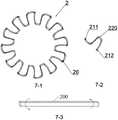
图6示出了图1中锚定结构的结构示意图;Fig. 6 shows the structural schematic diagram of the anchoring structure in Fig. 1;
图7示出了图6的仰视图;Fig. 7 shows the bottom view of Fig. 6;
图8示出了锚定结构在压握状态和展开状态的两种结构示意图;Figure 8 shows two structural schematic diagrams of the anchoring structure in a crimped state and an unfolded state;
图9示出了本发明实施例1提供的经导管置换瓣膜支架释放后夹持自体瓣叶的结构示意图;Fig. 9 shows the structural schematic diagram of clamping the native valve leaflet after the release of the transcatheter replacement valve stent provided in Example 1 of the present invention;
图10示出了实施例2中密封裙布的一种结构示意图;Figure 10 shows a schematic structural diagram of the sealing skirt in Example 2;
图11示出了实施例3中密封裙布的另一种结构示意图;Figure 11 shows another schematic structural diagram of the sealing skirt in Example 3;
图12示出了实施例3中密封裙布与支架主体缝合状态的结构示意图。FIG. 12 shows a schematic structural diagram of the state where the sealing skirt and the stent body are sewn together in Example 3. FIG.
附图标记说明:Description of reference numbers:
1、支架主体;2、锚定结构;20、锚定件;21、连接部;211、第一连接部;212、第二连接部;22、支撑部;220、折弯结构;221、第一折弯段;222、第二折弯段;200、锚定杆;3、裙撑结构;31、第一裙撑段;32、第二裙撑段;4、加强结构;41、加强杆;5、输送连接结构;51、连接杆;52、挂接部;6、瓣叶缝合耳;7、密封裙布;71、三角延伸段;8、人工瓣膜;9、自体瓣叶;91、前尖;92、后尖;10、心肌组织;11、房间隔;12、左心房;13、左心室。1. Main body of the stent; 2. Anchoring structure; 20. Anchoring piece; 21. Connecting part; 211. First connecting part; 212. Second connecting part; 22. Supporting part; 220. Bending structure; a bending section; 222, the second bending section; 200, the anchor rod; 3, the skirt structure; 31, the first skirt section; 32, the second skirt section; 4, the reinforcement structure; 41, the
具体实施方式Detailed ways
下面将结合附图对本发明的技术方案进行清楚、完整地描述,显然,所描述的实施例是本发明一部分实施例,而不是全部的实施例。基于本发明中的实施例,本领域普通技术人员在没有做出创造性劳动前提下所获得的所有其他实施例,都属于本发明保护的范围。The technical solutions of the present invention will be clearly and completely described below with reference to the accompanying drawings. Obviously, the described embodiments are part of the embodiments of the present invention, but not all of the embodiments. Based on the embodiments of the present invention, all other embodiments obtained by those of ordinary skill in the art without creative efforts shall fall within the protection scope of the present invention.
在本发明的描述中,需要说明的是,术语“中心”、“上”、“下”、“左”、“右”、“竖直”、“水平”、“内”、“外”等指示的方位或位置关系为基于附图所示的方位或位置关系,仅是为了便于描述本发明和简化描述,而不是指示或暗示所指的装置或元件必须具有特定的方位、以特定的方位构造和操作,因此不能理解为对本发明的限制。此外,术语“第一”、“第二”、“第三”仅用于描述目的,而不能理解为指示或暗示相对重要性。In the description of the present invention, it should be noted that the terms "center", "upper", "lower", "left", "right", "vertical", "horizontal", "inner", "outer", etc. The indicated orientation or positional relationship is based on the orientation or positional relationship shown in the accompanying drawings, which is only for the convenience of describing the present invention and simplifying the description, rather than indicating or implying that the indicated device or element must have a specific orientation or a specific orientation. construction and operation, and therefore should not be construed as limiting the invention. Furthermore, the terms "first", "second", and "third" are used for descriptive purposes only and should not be construed to indicate or imply relative importance.
在本发明的描述中,需要说明的是,除非另有明确的规定和限定,术语“安装”、“相连”、“连接”应做广义理解,例如,可以是固定连接,也可以是可拆卸连接,或一体地连接;可以是机械连接,也可以是电连接;可以是直接相连,也可以通过中间媒介间接相连,可以是两个元件内部的连通。对于本领域的普通技术人员而言,可以根据具体情况理解上述术语在本发明中的具体含义。In the description of the present invention, it should be noted that the terms "installed", "connected" and "connected" should be understood in a broad sense, unless otherwise expressly specified and limited, for example, it may be a fixed connection or a detachable connection Connection, or integral connection; can be mechanical connection, can also be electrical connection; can be directly connected, can also be indirectly connected through an intermediate medium, can be internal communication between two elements. For those of ordinary skill in the art, the specific meanings of the above terms in the present invention can be understood according to specific situations.
此外,下面所描述的本发明不同实施方式中所涉及的技术特征只要彼此之间未构成冲突就可以相互结合。In addition, the technical features involved in the different embodiments of the present invention described below can be combined with each other as long as they do not conflict with each other.
为了便于介绍本发明的技术方案,以下结合附图以及具体的实施例来详细说明,但实施例不应看作是对本发明的限制。In order to facilitate the introduction of the technical solutions of the present invention, detailed descriptions are given below with reference to the accompanying drawings and specific embodiments, but the embodiments should not be regarded as limitations of the present invention.
实施例1Example 1
一种经导管置换瓣膜支架,采用具有形状记忆功能的镍钛合金材料制成,可被径向压缩,经过导管输送,在达到位置后释放,可实现径向自膨胀展开成预制形状。经导管置换瓣膜支架,参照图1-图9,包括支架主体1和锚定结构2。其中,支架主体1为可径向压缩和展开的筒型框架结构,具有压握状态和展开状态;锚定结构2为围绕支架主体1的外周设置的封闭的框架结构;在支架主体1处于展开状态下,锚定结构2朝向支架主体1的外侧扩展,以使支架主体1锚定。A transcatheter replacement valve stent is made of nickel-titanium alloy material with shape memory function, can be compressed radially, is transported through a catheter, released after reaching the position, and can be radially self-expanded into a prefabricated shape. The transcatheter replacement valve stent, referring to FIGS. 1-9 , includes a
利用本发明的技术方案,因为锚定结构2为围绕支架主体1的外周设置的封闭的框架结构,使得相比于现有的多个独立的锚定杆200,在经导管置换瓣膜支架释放后,能够提供更加稳定的锚定力,闭环的框架结构存在相互的作用力,整体强度高,能为支架主体1提供更稳定的支撑力,有效的防止支架主体1发生周向的位移。With the technical solution of the present invention, because the anchoring
本发明提供的经导管置换瓣膜支架适用于主动脉瓣或二尖瓣置换。这里以二尖瓣置换瓣膜支架为例来说明本发明的技术方案。The transcatheter replacement valve stent provided by the present invention is suitable for aortic valve or mitral valve replacement. Here, a mitral valve replacement valve stent is taken as an example to illustrate the technical solution of the present invention.
进一步的,锚定结构2包括多个锚定件20,参照图6,锚定件20围绕支架主体1外周设置,锚定件20具有至少两个连接部21,锚定件20通过连接部21与支架主体1连接,相邻的两个连接部21之间通过支撑部22连接;在支架主体1处于展开状态下,支撑部22朝向支架主体1的外侧扩展,通过提供径向支撑力使支架主体1锚定。当支架主体1处于展开状态时,锚定件20释放在支架主体1的外周,并向外扩展,锚定件20能够对支架主体1提供径向的锚定力,使得支架主体1固定。作为一种优选的实施方式,多个锚定件20首尾相接设于支架主体1上,也可以是多个锚定件20均匀间隔设于支架主体1上,当相邻的锚定件20之间间隔设置时,锚定件20均与支架主体1连接,构成闭环的框架结构。多个锚定件20能为支架主体1的外周提供更加均衡的锚定力,使得二尖瓣的前尖91和后尖92都能受到均匀的夹持力,保证夹持稳定。Further, the anchoring
进一步的,本实施例中,锚定件20包括锚定杆200,参照图1、图6和图7,图6中的6-2和图7中的7-2所示为单根锚定杆200的结构示意图。锚定杆200的两端为连接部21,锚定杆200中部折弯构成支撑部22,锚定杆200的连接部21与支架主体1的第一端连接,在支架主体1处于展开状态下,锚定杆200的支撑部22朝向支架主体1的第二端延伸。Further, in this embodiment, the anchoring
具体的,以图2的方位来看,支架主体1具有相对设置的第一端和第二端,支架主体1的第一端也就是图2中的下端,也是流出端,支架主体1的第二端也就是图2中的上端,也是流入端。在支架主体1释放后,参照图9,支架主体1的第一端位于左心室13内,支架主体1的第二端位于左心房12内。Specifically, from the perspective of FIG. 2 , the bracket
进一步的,支撑部22具有折弯结构220。折弯结构220的数量可以是1个,也可以是多个。比如,当支撑部22设置一个折弯结构220时,锚定杆200类似倒置的“V”型;当支撑部22设置三个折弯结构220时,锚定杆200类似“M”型。Further, the
锚定杆200的中部设置折弯结构220,且锚定杆200的两端均与支架主体1连接,相比于一端与支架主体1连接,另一端为自由端的单根锚定杆的方案来说,本发明具有更出色的支撑力和稳定性,能防止支架主体1发生周向的偏移。The middle of the
具体的,本实施例中,锚定杆200的中部设置折弯结构220,参照图6中的6-2所示,锚定杆200的中部折弯后使得锚定杆200的两端均朝向支架主体1的第一端,锚定杆200的两端,也就是两个连接部21分别与支架主体1的第一端连接,在支架主体1处于展开状态下,锚定杆200中部的折弯结构220朝向支架主体1的第二端延伸。当然,连接部21也不限于锚定杆200的两端,也可以是靠近两端的其他部位。Specifically, in this embodiment, the middle part of the
进一步的,折弯结构220的外轮廓为圆滑的曲线。Further, the outer contour of the bending
折弯结构220的外轮廓为圆滑的曲线,能够防止锚定件20刺伤心肌组织10或扎破自体瓣叶9;且在手术过程中,单个的锚定杆200在释放过程中不可避免的会扯动腱索,而本发明因为具有圆滑的折弯结构220,更容易穿过腱索,解决了扯动腱索的问题。The outer contour of the bending
进一步的,锚定件20具有第一连接部211和第二连接部212,参照图6和图7,折弯结构220包括与第一连接部211连接的第一折弯段221,以及与第二连接部212连接的第二折弯段222,第一折弯段221和第二折弯段222之间具有相对扭转角,使锚定结构2形成螺旋状封闭的框架结构。Further, the
折弯结构220的第一折弯段221和第二折弯段222之间存在相对扭转角,使得第一折弯段221和第二折弯段222之间存在较强的相互作用力,当支架主体1释放后,当受外力作用时,支架主体1存在周向移位的趋势,因为第一折弯段221和第二折弯段222之间的相互作用力,使得第一折弯段221和第二折弯段222相互制约,保持支架主体1的固定位置,能够保证支架主体1和自体瓣环之间的同轴度,防止支架主体1发生周向偏移。There is a relative twist angle between the
进一步的,第一折弯段221和第二折弯段222的相对扭转角为45°~135°。Further, the relative twist angle of the
作为一种优选的实施方式,第一折弯段221和第二折弯段222的相对扭转角为90°。As a preferred embodiment, the relative twist angle of the
当锚定件20为一根锚定杆200时,连接部21和支撑部22连为一体,将锚定杆200从中部折弯形成锚定件20。当第一折弯段221和第二折弯段222之间存在相对扭转角时,因为在锚定杆200的中部扭转,着力点在于锚定杆200的两端,力臂长,如图7中的7-3所示,因此只需要较小的弯折力就能成型。When the anchoring
进一步的,锚定结构2与支架主体1的第一端连接,支架主体1处于压握状态下,锚定结构2在支架主体1的径向上不与支架主体1重叠。Further, the anchoring
当支架主体1处于压握状态,锚定结构2与支架主体1不重叠,能够缩小经导管置换瓣膜支架的径向尺寸,便于输送,解决了输送系统直径较大的问题。When the
具体的,本实施例中,锚定杆200的两端与支架主体1的第一端连接,通过工装热处理一体成型。参照图8,支架主体1在压握状态下,如图8中的8-1所示,锚定杆200为拉直状态,在径向上与支架主体1不存在重叠部分。也就是,锚定杆200沿支架主体1的轴向延伸。支架主体1释放后处于展开状态,如图8中的8-2所示,锚定杆200围绕其连接端朝向支架主体1的第二端翻折,锚定杆200与支架主体1在径向上重叠,锚定杆200的支撑部22朝向支架主体1的第二端延伸。Specifically, in this embodiment, both ends of the
现有的置换瓣膜依靠径向支撑力来锚定,为了提供更大的锚定力,不得不增大支架整体的径向尺寸,这会导致传导阻滞;另外,支架压握后尺寸较大,会增大输送阻力,导致器械输送困难。本发明在压握状态下,锚定杆200能够翻折至与支架主体1在径向上不重叠,使得经导管置换瓣膜支架在压握状态下只有单层,支架主体1,和锚定杆200连为一体,能够有效缩减经导管置换瓣膜支架的输送尺寸,保证输送过程更加顺畅,同时保证经导管置换瓣膜支架的可回收性。需要说明的是,这里的“回收”是指将已经释放的部分再收回鞘管内。Existing replacement valves rely on radial support force for anchoring. In order to provide greater anchoring force, the overall radial size of the stent has to be increased, which will lead to conduction block; in addition, the stent has a larger size after crimping. , which will increase the delivery resistance and make it difficult to deliver the device. In the crimped state of the present invention, the
进一步的,经导管置换瓣膜支架还包括裙撑结构3,裙撑结构3设于支架主体1上,裙撑结构3环绕支架主体1一周并朝向支架主体1的外侧扩展,在支架主体1处于展开状态下,裙撑结构3和锚定结构2构成第一夹持机构,夹持机构适于夹持自体瓣叶9。Further, the transcatheter replacement valve stent also includes a
进一步的,参照图4,裙撑结构3包括与支架主体1连接的第一裙撑段31以及与第一裙撑段31连接的第二裙撑段32,第一裙撑段31向外弯曲设置,第二裙撑段32向内弯曲设置。作为一种优选的实施方式,第一裙撑段31与支架主体1之间圆滑相接,第一裙撑段31和第二裙撑段32圆滑相接。需要说明的是,第一裙撑段31向外弯曲,是指,第一裙撑段31朝向远离支架主体1中心的一侧弯曲,相应的,第二裙撑段32向内弯曲,是指,第二裙撑段32朝向靠近支架主体1的一侧弯曲。因此,第一裙撑段31和第二裙撑段32朝向相反的方向弯曲。裙撑结构3可形象的看作是盘型的网状支架,如图1、图2和图4所示。裙撑结构3为柔性的密封裙布7的缝合提供支撑。密封裙布7将在后续介绍。参照图9,第二裙撑段32弯曲后能够贴合心肌组织10或房间隔11,能够提高密封效果,防止发生瓣周漏。第一裙撑段31和第二裙撑段32之间,或第二裙撑段32与支架主体1之间具有网格口。Further, referring to FIG. 4 , the
作为一种优选的实施方式,锚定杆200的支撑部22延伸至第一裙撑段31和第二裙撑段32之间的网格口内。As a preferred embodiment, the
另外,锚定结构2和裙撑结构3构成第一夹持机构,能够夹持自体瓣叶9,使得支架主体1的锚定更加稳固,防止支架主体1产生沿其轴向的位移。在锚定结构2提供径向支撑力的同时,本发明还能够通过锚定结构2与裙撑结构3配合,对自体瓣叶9进行夹持,保证经导管置换瓣膜不移位,避免产生瓣周漏或引发其他并发症。另外,因为裙撑结构3位于自体瓣叶9的心房侧,能够夹持自体瓣叶9的根部,夹持更稳定,保证经导管置换瓣膜不易发生沿支架主体1的径向和轴向的移位。In addition, the anchoring
具体的,支撑部22与裙撑结构3的第二裙撑段32配合,在心室收缩时,夹持自体瓣叶9,防止经导管置换瓣膜移位,防止瓣周漏。Specifically, the
以图2的方位来看,裙撑结构32朝向支架主体1的外侧扩展,锚定杆200也设于支架主体1的外侧,裙撑结构3与锚定杆200的支撑部22在支架主体1的外周构成第一夹持机构,如前述所说,参照图8,经导管置换瓣膜支架释放后,裙撑结构3位于左心房12,也就是位于自体瓣叶9的上部,锚定杆200位于左心室13,也就是位于自体瓣叶9的下部,裙撑结构3与锚定杆200将自体瓣叶9夹持其中。From the orientation of FIG. 2 , the
裙撑结构3为环形的框架结构,而锚定杆200围绕支架主体1一周,因此,裙撑结构3和锚定杆200之间围绕支架主体1构成多个夹持点。参照图6,本实施例中,锚定杆200设置有12根,具体的,锚定杆200的支撑部22延伸至裙撑结构3的网格口处。裙撑结构3的网格口至少有两根裙撑杆能够对自体瓣叶9起到夹持作用,相比于锚定杆200与裙撑结构3的单根裙撑杆对应配合来夹持自体瓣叶9的方案而言,锚定杆200的支撑部22延伸至裙撑结构3的网格口处,至少存在两根裙撑杆与锚定杆200配合夹持自体瓣叶9,夹持面积大,夹持更稳定。The
在支架主体1展开后,第一折弯段221与支架主体1的外壁之间至少存在部分贴合,构成第二夹持机构,用于夹持自体瓣叶9,而第二折弯段222由于与第一折弯段221之间存在相对扭转角,能够为夹持提供压力,使第二夹持机构夹持更紧;围绕支架主体1一周的12个锚定件20与支架主体1之间形成了圆柱型的夹持面,夹持面积增大,与第一夹持机构共同夹持自体瓣叶9,夹持更稳定,同时,密封效果也更好。After the
进一步的,相邻的两个锚定件20之间连接有加强结构4,能够进一步提高锚定件20的强度和稳定性,进一步防止支架主体1发生周向的偏移,保证各锚定结构2的横向稳定性,以图2的方位来看,也可以说是水平稳定性,保证支架主体1和自体瓣环之间的同轴度,避免支架主体1发生移位而发生瓣周漏。Further, the reinforcing
进一步的,加强结构4包括加强杆41,加强杆41为V型、U型、W型中的一个或多个的组合。本实施例中,加强杆41的两端分别与相邻的两个连接部21连接。参照图1,本实施例中,加强杆41为V型。Further, the reinforcing
进一步的,经导管置换瓣膜支架整体从鞘管中释放的过程中,若释放位置定位不准,可以回收,也就是将经导管置换瓣膜支架整体收回鞘管中,调整位置后再重新释放。为了保证经导管置换瓣膜支架整体能够顺利回收,在压缩状态下,V型的加强杆41的尖端的朝向与经导管置换瓣膜支架的释放方向相同。在释放过程中,支架主体1的第一端先于第二端释放,也就是,图2中支架主体1的下端先于上端释放,在压握状态下,V型的加强杆41的尖端朝下,也就是,当定位不准确需要将经导管置换瓣膜支架回收进鞘管中时,V型的加强杆41的尖端朝下被收回。展开后,锚定杆200围绕其连接端向外翻折后,呈现图2所示的状态,也就是展开状态,此时,V型的加强杆41的尖端朝上。Further, in the process of releasing the entire transcatheter replacement valve stent from the sheath, if the release position is not positioned correctly, it can be recovered, that is, the entire transcatheter replacement valve stent is retracted into the sheath, and the position is adjusted and then released again. In order to ensure that the entire transcatheter replacement valve stent can be recovered smoothly, in the compressed state, the tip of the V-shaped reinforcing
进一步的,支架主体1的第二端设有输送连接结构5,输送连接结构5包括围绕支架主体1一周设置的多个连接杆51,连接杆51的一端与支架主体1的第二端连接,连接杆51的另一端沿支架主体1的轴向远离支架主体1的第二端延伸,并在端部设置挂接部52,挂接部52适于与输送系统连接。Further, the second end of the
挂接部52凸出于连接杆51设置,有利于为与输送系统连接提供着力点,同时,能够防止裙撑结构3在释放过程中产生冲击力,导致锚定件20移位甚至引起心脏损伤。本实施例中,连接杆51设置六根,且围绕支架主体1一周均匀间隔设置,挂接部52为垂直于连接杆51设置的横杆。当然,挂接部52也可以是圆环或其他凸出于连接杆51的结构。The hooking
进一步的,支架主体1围绕支架主体1一周设有多个瓣叶缝合耳6。参照图4,瓣叶缝合耳6为设在支架主体1上的缝合孔,为生物或非生物柔性材料的人工瓣膜8的缝合提供了支撑。Further, the
实施例2Example 2
一种经导管置换瓣膜装置,包括实施例1中所述的经导管置换瓣膜支架。A transcatheter replacement valve device, comprising the transcatheter replacement valve stent described in
进一步的,本实施例中,经导管置换瓣膜还包括密封裙布7,密封裙布7的结构如图10所示。另参照图9,密封裙布7连接在裙撑结构3上,密封裙布7围绕支架主体1一圈贴合地设于支架主体1的内侧,密封裙布7的第一端与裙撑结构3连接,密封裙布7的第二端朝向支架主体1的第一端延伸。Further, in this embodiment, the transcatheter replacement valve further includes a sealing
进一步的,经导管置换瓣膜支架还包括瓣叶缝合耳6,密封裙布7的第二端部分或完全覆盖瓣叶缝合耳6,可以有效增强密封效果,防止瓣周漏。Further, the transcatheter replacement valve stent also includes
进一步的,支架主体1的内侧通过瓣叶缝合耳6缝合连接有人工瓣膜8;人工瓣膜8设有两片,适于置换患者的二尖瓣;或,人工瓣膜8设有三片,适于置换患者的主动脉瓣。Further, the inner side of the
经皮导管是一种用针头插入皮肤的导管。所有导管都是中空的导管,允许液体进入体内,或允许将多余的体液通过导管排出体外,送到合适的处置容器中。A percutaneous catheter is a catheter that is inserted into the skin with a needle. All catheters are hollow tubes that allow fluids to enter the body or allow excess body fluids to be expelled from the body through the catheter to a suitable disposal container.
实施例3Example 3
一种经导管置换瓣膜装置,包括实施例1中所述的经导管置换瓣膜支架。与实施例2的区别在于,如图11所示,密封裙布7还可以设置位于远端的三角延伸段71,给予更高的密封效果,密封裙布7缝合于支架主体1上的位置如图12所示,密封裙布7的三角延伸段与支架主体菱形网格所外露的三角形窗口相适配。A transcatheter replacement valve device, comprising the transcatheter replacement valve stent described in
适用于二尖瓣的经导管置换瓣膜装置的使用方法,包括以下步骤:A method of using a transcatheter valve device for mitral valve replacement, comprising the following steps:
步骤S1:穿刺患者的一侧股静脉,将导丝、穿刺鞘管送入右心房,穿刺房间隔11,通过二尖瓣进入左心室13;Step S1: puncture one side of the patient's femoral vein, send the guide wire and the puncture sheath into the right atrium, puncture the
步骤S2:将所述经导管置换瓣膜装置装入相应的输送系统,沿导丝轨道将输送系统送入左心室13;Step S2: loading the transcatheter valve replacement device into the corresponding delivery system, and sending the delivery system into the
步骤S3:通过输送系统上的标记,调整输送系统方向,先释放锚定杆200,再释放瓣叶缝合耳6及裙撑结构3,使裙撑结构3撑在左心房12的底部,最后释放输送连接结构5;Step S3: Adjust the direction of the delivery system according to the mark on the delivery system, first release the
步骤S4:将介入二尖瓣的输送系统退至右心房12,送入房间隔11封堵器,封堵房间隔11,完成手术。Step S4 : the delivery system intervening in the mitral valve is withdrawn to the
以上步骤中,通过鞘管单向后撤完成定位、固定、释放三个步骤,有效降低输送系统的径向尺寸,减少输送系统头端对室间隔的压迫和损害。In the above steps, the three steps of positioning, fixing and releasing are completed by unidirectional retraction of the sheath, which effectively reduces the radial size of the delivery system and reduces the compression and damage of the ventricular septum by the head end of the delivery system.
手术流程:穿刺股静脉经房间隔11入路,穿刺室间隔,建立左心室13至右心室导丝轨道,沿导丝送入介入经导管置换瓣膜装置,释放锚定杆200,后撤鞘管,释放置换瓣膜。封堵房间隔11,手术结束。Operation procedure: puncture the femoral vein through the
根据上述描述,本专利申请具有以下优点:According to the above description, the present patent application has the following advantages:
1、锚定结构2为围绕支架主体1的外周设置的封闭的框架结构,能够提供更加稳定的锚定力,防止支架主体1发生周向的位移;锚定杆200的中部设置折弯结构220,折弯结构220的第一折弯段221和第二折弯段222之间存在相对扭转角,具有更出色的支撑力和稳定性,能防止支架主体1发生周向的偏移;1. The anchoring
2、锚定结构2和裙撑结构3构成第一夹持机构,能够夹持自体瓣叶9,使得支架主体1的锚定更加稳固,进一步防止支架主体1沿其轴向的位移;第一折弯段221与支架主体1之间构成第二夹持机构,进一步提高支架主体1的稳定性;2. The anchoring
3、在支架主体1的压握状态下,锚定结构2与支架主体1不重叠,能够缩小经导管置换瓣膜支架在压握状态下的径向尺寸,便于输送,解决了输送系统直径较大的问题。3. In the crimping state of the
显然,上述实施例仅仅是为清楚地说明所作的举例,而并非对实施方式的限定。对于所属领域的普通技术人员来说,在上述说明的基础上还可以做出其它不同形式的变化或变动。这里无需也无法对所有的实施方式予以穷举。而由此所引伸出的显而易见的变化或变动仍处于本发明创造的保护范围之中。Obviously, the above-mentioned embodiments are only examples for clear description, and are not intended to limit the implementation manner. For those of ordinary skill in the art, changes or modifications in other different forms can also be made on the basis of the above description. There is no need and cannot be exhaustive of all implementations here. And the obvious changes or changes derived from this are still within the protection scope of the present invention.
Claims (20)
Priority Applications (2)
| Application Number | Priority Date | Filing Date | Title |
|---|---|---|---|
| CN202210772820.7ACN115153962A (en) | 2022-06-30 | 2022-06-30 | A transcatheter valve replacement device and its stent |
| PCT/CN2022/119896WO2024000835A1 (en) | 2022-06-30 | 2022-09-20 | Transcatheter valve replacement device and stent thereof |
Applications Claiming Priority (1)
| Application Number | Priority Date | Filing Date | Title |
|---|---|---|---|
| CN202210772820.7ACN115153962A (en) | 2022-06-30 | 2022-06-30 | A transcatheter valve replacement device and its stent |
Publications (1)
| Publication Number | Publication Date |
|---|---|
| CN115153962Atrue CN115153962A (en) | 2022-10-11 |
Family
ID=83488656
Family Applications (1)
| Application Number | Title | Priority Date | Filing Date |
|---|---|---|---|
| CN202210772820.7APendingCN115153962A (en) | 2022-06-30 | 2022-06-30 | A transcatheter valve replacement device and its stent |
Country Status (1)
| Country | Link |
|---|---|
| CN (1) | CN115153962A (en) |
Citations (6)
| Publication number | Priority date | Publication date | Assignee | Title |
|---|---|---|---|---|
| CN108366858A (en)* | 2015-11-10 | 2018-08-03 | 爱德华兹生命科学公司 | Transcatheter heart valve for replacement of native mitral valve |
| CN209377809U (en)* | 2018-10-15 | 2019-09-13 | 上海微创心通医疗科技有限公司 | A kind of heart valve prosthesis prosthese and its bracket |
| CN112716658A (en)* | 2021-01-20 | 2021-04-30 | 上海捍宇医疗科技股份有限公司 | Transcatheter atrioventricular valve replacement system |
| CN112754731A (en)* | 2021-01-20 | 2021-05-07 | 上海纽脉医疗科技有限公司 | Interventional artificial heart valve and medical device |
| CN113730036A (en)* | 2021-09-30 | 2021-12-03 | 宁波健世科技股份有限公司 | Heart valve prosthesis capable of being anchored with autologous valve leaflet |
| CN114176842A (en)* | 2021-12-28 | 2022-03-15 | 胡佳 | Valve stent for valve replacement and method of releasing the same |
- 2022
- 2022-06-30CNCN202210772820.7Apatent/CN115153962A/enactivePending
Patent Citations (6)
| Publication number | Priority date | Publication date | Assignee | Title |
|---|---|---|---|---|
| CN108366858A (en)* | 2015-11-10 | 2018-08-03 | 爱德华兹生命科学公司 | Transcatheter heart valve for replacement of native mitral valve |
| CN209377809U (en)* | 2018-10-15 | 2019-09-13 | 上海微创心通医疗科技有限公司 | A kind of heart valve prosthesis prosthese and its bracket |
| CN112716658A (en)* | 2021-01-20 | 2021-04-30 | 上海捍宇医疗科技股份有限公司 | Transcatheter atrioventricular valve replacement system |
| CN112754731A (en)* | 2021-01-20 | 2021-05-07 | 上海纽脉医疗科技有限公司 | Interventional artificial heart valve and medical device |
| CN113730036A (en)* | 2021-09-30 | 2021-12-03 | 宁波健世科技股份有限公司 | Heart valve prosthesis capable of being anchored with autologous valve leaflet |
| CN114176842A (en)* | 2021-12-28 | 2022-03-15 | 胡佳 | Valve stent for valve replacement and method of releasing the same |
Similar Documents
| Publication | Publication Date | Title |
|---|---|---|
| US12427015B2 (en) | Prosthetic valve and deployment system | |
| US12144732B2 (en) | Heart valve prosthesis anchored to interventricular septum and conveying and releasing method thereof | |
| CN109789018B (en) | Prosthetic valve with coaxial frame | |
| CN110603007A (en) | Devices and methods for transcatheter mitral and tricuspid valve repair | |
| EP3909548B1 (en) | Transcatheter mitral valve fixation concepts | |
| CN118662279A (en) | Cardiac implant | |
| CN114502105A (en) | docking element | |
| CN104334119A (en) | Single-ring cardiac valve support | |
| CN110141399A (en) | Prosthetic valve with axial sliding frame | |
| CN106572905A (en) | Convoluted anchor for supporting a prosthetic heart valve, prosthetic heart valve and deployment device | |
| CN113616384A (en) | Valve prosthesis with connecting part | |
| US20220313428A1 (en) | Frame Features for Transcatheter Mitral Valve Replacement Device | |
| US20220031452A1 (en) | Prosthesic heart valve | |
| CN113730034A (en) | Transcatheter implanted mitral valve device | |
| CN115252222B (en) | Transcatheter replacement valve device and stent thereof | |
| CN116269942A (en) | Artificial heart valve | |
| CN118078497B (en) | Double-layer anchoring intervention mitral valve replacement prosthesis | |
| CN114469444B (en) | Valve stents and valve prostheses | |
| CN115153962A (en) | A transcatheter valve replacement device and its stent | |
| HK40080464A (en) | Transcatheter valve replacement device and support thereof | |
| CN115252223A (en) | A transcatheter valve replacement device and its stent | |
| CN117137683A (en) | Anchor stents, cardiac valve regurgitation replacement components and anchor stent delivery devices | |
| CN115317196A (en) | Transcatheter valve replacement device and stent thereof | |
| CN115227451A (en) | A transcatheter valve replacement device and its stent | |
| WO2024000835A1 (en) | Transcatheter valve replacement device and stent thereof |
Legal Events
| Date | Code | Title | Description |
|---|---|---|---|
| PB01 | Publication | ||
| PB01 | Publication | ||
| SE01 | Entry into force of request for substantive examination | ||
| SE01 | Entry into force of request for substantive examination | ||
| REG | Reference to a national code | Ref country code:HK Ref legal event code:DE Ref document number:40080464 Country of ref document:HK |