CN115153707A - a vascular stapler - Google Patents
a vascular staplerDownload PDFInfo
- Publication number
- CN115153707A CN115153707ACN202210949437.4ACN202210949437ACN115153707ACN 115153707 ACN115153707 ACN 115153707ACN 202210949437 ACN202210949437 ACN 202210949437ACN 115153707 ACN115153707 ACN 115153707A
- Authority
- CN
- China
- Prior art keywords
- head
- driving
- column
- anastomosis
- calibration
- Prior art date
- Legal status (The legal status is an assumption and is not a legal conclusion. Google has not performed a legal analysis and makes no representation as to the accuracy of the status listed.)
- Granted
Links
Images


Classifications
- A—HUMAN NECESSITIES
- A61—MEDICAL OR VETERINARY SCIENCE; HYGIENE
- A61B—DIAGNOSIS; SURGERY; IDENTIFICATION
- A61B17/00—Surgical instruments, devices or methods
- A61B17/11—Surgical instruments, devices or methods for performing anastomosis; Buttons for anastomosis
- A—HUMAN NECESSITIES
- A61—MEDICAL OR VETERINARY SCIENCE; HYGIENE
- A61B—DIAGNOSIS; SURGERY; IDENTIFICATION
- A61B90/00—Instruments, implements or accessories specially adapted for surgery or diagnosis and not covered by any of the groups A61B1/00 - A61B50/00, e.g. for luxation treatment or for protecting wound edges
- A61B90/10—Instruments, implements or accessories specially adapted for surgery or diagnosis and not covered by any of the groups A61B1/00 - A61B50/00, e.g. for luxation treatment or for protecting wound edges for stereotaxic surgery, e.g. frame-based stereotaxis
- A61B90/14—Fixators for body parts, e.g. skull clamps; Constructional details of fixators, e.g. pins
- A61B90/17—Fixators for body parts, e.g. skull clamps; Constructional details of fixators, e.g. pins for soft tissue, e.g. breast-holding devices
- A—HUMAN NECESSITIES
- A61—MEDICAL OR VETERINARY SCIENCE; HYGIENE
- A61B—DIAGNOSIS; SURGERY; IDENTIFICATION
- A61B17/00—Surgical instruments, devices or methods
- A61B17/11—Surgical instruments, devices or methods for performing anastomosis; Buttons for anastomosis
- A61B2017/1107—Surgical instruments, devices or methods for performing anastomosis; Buttons for anastomosis for blood vessels
- A—HUMAN NECESSITIES
- A61—MEDICAL OR VETERINARY SCIENCE; HYGIENE
- A61B—DIAGNOSIS; SURGERY; IDENTIFICATION
- A61B17/00—Surgical instruments, devices or methods
- A61B17/11—Surgical instruments, devices or methods for performing anastomosis; Buttons for anastomosis
- A61B2017/1132—End-to-end connections
Landscapes
- Health & Medical Sciences (AREA)
- Surgery (AREA)
- Life Sciences & Earth Sciences (AREA)
- Animal Behavior & Ethology (AREA)
- Medical Informatics (AREA)
- Veterinary Medicine (AREA)
- Nuclear Medicine, Radiotherapy & Molecular Imaging (AREA)
- Engineering & Computer Science (AREA)
- Biomedical Technology (AREA)
- Heart & Thoracic Surgery (AREA)
- Public Health (AREA)
- Molecular Biology (AREA)
- General Health & Medical Sciences (AREA)
- Neurosurgery (AREA)
- Pathology (AREA)
- Oral & Maxillofacial Surgery (AREA)
- Surgical Instruments (AREA)
Abstract
Translated fromChinese
Description
Translated fromChinese技术领域technical field
本发明涉及血管吻合器械领域,具体涉及一种血管吻合器。The invention relates to the field of vascular anastomosis instruments, in particular to a vascular anastomosis device.
背景技术Background technique
在进行肝移植、肾移植、心脏移植以及肺移植等大血管的吻合时,脏器切除后新脏器植入最困难和技术要求最高的部分就是供受体内脏上动静脉血管的吻合修复重建,对手术成功率和术后恢复具有决定性意义。手术时间越短,越有利于肝、肾、心脏以及肺移植的术后恢复,尽早维持体循环,减少患者并发症的发生率,有利于移植物尽快复活。When performing anastomosis of large blood vessels such as liver transplantation, kidney transplantation, heart transplantation, and lung transplantation, the most difficult and technically demanding part of new organ implantation after organ resection is the anastomotic repair and reconstruction of the superior visceral artery and vein of the donor and recipient. , which is decisive for the success rate of surgery and postoperative recovery. The shorter the operative time, the more conducive to the postoperative recovery of liver, kidney, heart and lung transplantation, maintain the systemic circulation as soon as possible, reduce the incidence of complications in patients, and facilitate the rapid resurrection of the graft.
现目前在进行血管吻合时,可通过吻合环进行两血管断端之间的吻合,吻合时,将每根血管断端穿过对应的吻合环,再将血管断端的内膜外翻并使血管壁穿挂在吻合环的针体上固定,最后再将两个吻合环扣合即可完成血管的吻合。相比于用针线缝合,吻合环吻合血管能够使两血管间的连接更紧密,吻合效果更好。At present, when performing vascular anastomosis, the anastomosis between the two blood vessel ends can be performed through an anastomosis ring. During anastomosis, each blood vessel broken end is passed through the corresponding anastomotic ring, and then the intima of the blood vessel broken end is everted and made The blood vessel wall is fixed on the needle body of the anastomotic ring, and finally the two anastomotic rings are buckled to complete the blood vessel anastomosis. Compared with suture with needle and thread, the anastomotic ring anastomotic blood vessel can make the connection between the two blood vessels tighter and the anastomosis effect is better.
但是,现目前使用吻合环吻合血管时,仍需医生手动将血管断端的血管壁固定在吻合环的各个针体上,需重复操作多次,操作难度大且耗时较长,并且医生难以把控每次固定时血管壁的牵拉外翻程度,容易导致各个固定位置的血管壁的延展程度不一致,进而导致血管吻合效果不佳。However, when an anastomotic ring is currently used for anastomotic blood vessels, the doctor still needs to manually fix the blood vessel wall at the broken end of the blood vessel on each needle body of the anastomotic ring, and the operation needs to be repeated many times. The operation is difficult and time-consuming, and the doctor is difficult to Controlling the degree of traction and eversion of the blood vessel wall during each fixation may easily lead to inconsistent extension of the blood vessel wall at each fixation position, resulting in poor vascular anastomosis results.
发明内容SUMMARY OF THE INVENTION
针对现有技术存在的不足,本发明提出一种血管吻合器,以解决现目前仍需医生手动将血管断端固定在吻合环上,需重复操作多次,操作难度大且耗时较长,并且医生难以把控每次固定时血管壁的牵拉外翻程度,容易导致各个固定位置的血管壁的延展程度不一致,进而导致血管吻合效果不佳的问题。Aiming at the shortcomings of the prior art, the present invention proposes a vascular stapler to solve the problem that the doctor still needs to manually fix the broken end of the blood vessel on the anastomotic ring, which requires repeated operations many times, and the operation is difficult and time-consuming. In addition, it is difficult for doctors to control the degree of traction and eversion of the blood vessel wall during each fixation, which may easily lead to inconsistent extension of the blood vessel wall at each fixation position, which in turn leads to the problem of poor blood vessel anastomosis.
本发明的目的通过以下技术方案实现:The object of the present invention is achieved through the following technical solutions:
本发明提供的一种血管吻合器,包括:A vascular stapler provided by the present invention includes:
吻合部,其顶部安装有两个卡置部,所述吻合部用于驱动两个卡置部彼此靠近或远离;an anastomosis part, the top of which is installed with two clamping parts, and the anastomosis parts are used to drive the two clamping parts to approach or move away from each other;
吻合环,于每个所述卡置部上可拆卸地各安装一个,两个所述吻合环朝向彼此的一侧周向均布有多个针体,且所述吻合环上相邻的两个针体之间均设置有插槽;An anastomotic ring, one of which is detachably installed on each of the clamping parts, a plurality of needle bodies are evenly distributed on the sides of the two anastomotic rings facing each other, and two adjacent needles on the anastomotic rings There are slots between the bodies;
固定机构,其包括驱动组件和校准柱头,所述校准柱头的一端为端头,所述校准柱头位于两个吻合环之间,所述校准柱头的外侧周向均布有多个抵片,每个所述抵片的首端均与校准柱头铰接,所述驱动组件用于驱动所有抵片同步转动,以使所述抵片的末端能够靠近或远离端头;及The fixing mechanism includes a drive assembly and a calibration stud, one end of the calibration stud is an end, the calibration stud is located between the two anastomotic rings, and a plurality of contact pieces are evenly distributed on the outer circumference of the calibration stud, each of which is The head ends of the abutting pieces are all hinged with the calibration column head, and the driving component is used to drive all the abutting pieces to rotate synchronously, so that the ends of the abutting pieces can approach or be far away from the end head; and
调位机构,其用于驱动所述校准柱头在两个吻合环之间移动,以使所述端头能够分别对准两个吻合环的中心并朝该中心移动。The positioning mechanism is used for driving the alignment column head to move between the two anastomotic rings, so that the end heads can be aligned with the centers of the two anastomotic rings respectively and move toward the center.
进一步的,所述吻合部的顶部开设有滑动槽,所述滑动槽内设置有能够轴向转动的从动杆,所述从动杆的表面具有两个呈对称设置且旋向相反的螺纹段,且两螺纹段的衔接处安装有第一锥齿轮,两个所述卡置部的底部分别可滑动地安装于滑动槽内并分别与两处螺纹段传动连接,所述吻合部内安装有能够轴向转动的主动杆,所述主动杆的一端贯穿吻合部的底部并设置有吻合旋钮,所述主动杆的另一端贯穿吻合部的顶部并设置有第二锥齿轮,所述第二锥齿轮与第一锥齿轮传动连接。Further, a sliding groove is provided on the top of the anastomosis portion, and a driven rod capable of axial rotation is arranged in the sliding groove, and the surface of the driven rod has two threaded segments arranged symmetrically and rotated in opposite directions. , and a first bevel gear is installed at the joint of the two thread segments, the bottoms of the two clamping parts are respectively slidably installed in the sliding grooves and are respectively connected with the two thread segments. An axially rotating driving rod, one end of the driving rod penetrates the bottom of the anastomosis part and is provided with an anastomosis knob, and the other end of the driving rod penetrates the top of the anastomosis part and is provided with a second bevel gear, the second bevel gear Connected with the first bevel gear.
进一步的,所述卡置部包括支起柱和U型扣,所述支起柱可滑动地安装于滑动槽内并向上延伸,所述U型扣安装于支起柱的顶部并支出吻合部的一侧,所述吻合环的外圈周向设置有卡置槽,且所述吻合环通过卡置槽卡入U型扣内。Further, the clamping part includes a support column and a U-shaped buckle, the support column is slidably installed in the sliding groove and extends upward, and the U-shaped buckle is installed on the top of the support column and pays out the matching part. On one side of the anastomotic ring, an outer ring of the anastomotic ring is provided with a clamping groove in the circumferential direction, and the anastomotic ring is clamped into the U-shaped buckle through the clamping groove.
进一步的,所述驱动组件包括操作管、驱动柱和驱动头,所述操作管的内部具有管腔,所述校准柱头设置于操作管的顶端一侧且端头朝外,所述校准柱头的内部具有与管腔连通的驱动腔,所述校准柱头对应每个抵片的侧壁上均开设有第一侧槽,每个所述抵片分别与第一侧槽靠近端头的一端铰接并通过第一弹性件与第一侧槽内壁连接,所述第一弹性件能够提供将抵片末端推向驱动腔的弹性力,所述驱动头可滑动地安装于驱动腔内且末端位于管腔内,所述驱动头上对应每个抵片周向均布有多个抵柱,各个所述抵柱分别位于第一侧槽内并与抵片抵接,所述驱动头通过第二弹性件与校准柱头连接,所述第二弹性件能够提供将驱动头朝管腔方向移动的弹性力,所述驱动柱可滑动地安装于管腔内且底端穿出操作管,所述驱动柱的顶端朝向校准柱头的一侧呈倾斜斜面并与驱动头的末端抵接。Further, the drive assembly includes an operation tube, a drive column and a drive head, the inside of the operation tube has a lumen, the calibration column head is arranged on one side of the top end of the operation tube with the end facing outward, and the calibration column head has a lumen. There is a driving cavity in communication with the lumen, and a first side groove is opened on the side wall of the calibration stud corresponding to each abutting piece, and each of the abutting pieces is hinged with one end of the first side groove close to the end head and The first elastic member is connected with the inner wall of the first side groove, the first elastic member can provide elastic force to push the end of the contact piece to the driving cavity, the driving head is slidably installed in the driving cavity and the end is located in the lumen Inside, a plurality of abutment posts are evenly distributed on the drive head in the circumferential direction corresponding to each abutment piece, each of the abutment posts is located in the first side groove and abuts against the abutment piece, and the drive head is aligned with the The column head is connected, the second elastic member can provide an elastic force to move the driving head toward the lumen, the driving column is slidably installed in the lumen and the bottom end passes through the operation tube, and the top end of the driving column faces One side of the calibration column head is beveled and abuts the end of the drive head.
进一步的,所述抵片的数量为一个吻合环上针体和插槽的数量之和,每个所述抵片的末端均开设有豁口,且每个所述抵片靠近端头的一侧位于豁口两侧的位置上均设置有固定刺。Further, the number of the abutting pieces is the sum of the number of needle bodies and slots on an anastomotic ring, the end of each of the abutting pieces is provided with a gap, and each of the abutting pieces is close to the side of the end. The positions on both sides of the gap are provided with fixed thorns.
进一步的,所述校准柱头位于第一侧槽与端头之间的侧壁上相对设置有两个第二侧槽,两个所述第二侧槽内均可滑动地安装有固定柱,两个所述固定柱之间连接有第三弹性件,所述第三弹性件能够提供将两个固定柱拉向驱动腔的弹性力,所述驱动头靠近端头的一端设置有锥形头,该锥形头的两侧面分别与两固定柱靠近彼此的一端抵接。Further, two second side grooves are oppositely arranged on the side wall of the calibration column head located between the first side groove and the end head, and fixed columns can be slidably installed in the two second side grooves. A third elastic member is connected between each of the fixing columns, and the third elastic member can provide elastic force for pulling the two fixing columns to the driving cavity, and a tapered head is provided at one end of the driving head close to the end head, The two side surfaces of the conical head are respectively abutted against one end of the two fixing posts close to each other.
进一步的,所述调位机构包括主柱体和转柱,所述主柱体安装于吻合部位于U型扣支出的一侧,所述主柱体内设置有贯通其顶部和底部的转孔,所述转孔靠近两个U型扣的两侧分别设置有移动槽,所述转柱可轴向转动地安装于转孔内,所述转柱的一侧开设有侧容纳槽,所述操作管可滑动地安装于侧容纳槽内且两端穿出主柱体,当转柱转动至侧容纳槽与某一移动槽连通时,所述操作管可移动至移动槽内,并使校准柱头移向该侧的吻合环。Further, the position adjustment mechanism includes a main cylinder and a rotating cylinder, the main cylinder is installed on the side where the anastomosis portion is located at the outgoing side of the U-shaped buckle, and the main cylinder is provided with a rotating hole penetrating the top and bottom thereof, The two sides of the rotating hole close to the two U-shaped buckles are respectively provided with moving grooves, the rotating column can be axially rotatably installed in the rotating hole, and one side of the rotating column is provided with a side accommodating groove. The tube is slidably installed in the side accommodating groove and protrudes from the main cylinder at both ends. When the rotating column rotates until the side accommodating groove communicates with a certain moving groove, the operating tube can move into the moving groove and align the column head. Move towards the anastomotic ring on that side.
进一步的,两个所述移动槽远离彼此的一侧分别贯穿安装有推柱,每个所述推柱的一端均位于主柱体内并设置有推板,且每个所述推柱的另一端均位于主柱体外,两个所述推柱均能沿靠近或远离彼此的方向滑动,所述转柱远离侧容纳槽的一侧对应推板设置有推入槽。Further, push columns are installed through the two moving grooves away from each other, one end of each push column is located in the main column and is provided with a push plate, and the other end of each push column is provided with a push plate. Both are located outside the main column, the two push columns can slide in the direction of approaching or away from each other, and the side of the rotating column away from the side accommodating slot is provided with a push-in slot corresponding to the push plate.
进一步的,所述操作管的底端设置有下限位圈且顶端位于校准柱头下方的位置处设置有上限位圈,当所述下限位圈与转柱抵接时校准柱头与吻合环处于同一高度,当所述上限位圈与转柱抵接时校准柱头处于U型扣的下方。Further, the bottom end of the operating tube is provided with a lower limit ring, and the top end is provided with an upper limit ring at the position below the calibration column head. When the lower limit ring is in contact with the rotating column, the calibration column head and the anastomotic ring are at the same height. , when the upper limit ring is in contact with the rotating column, the calibration column head is located below the U-shaped buckle.
进一步的,所述主柱体的顶部位于转孔的两侧分别设置有限位块,所述转柱的顶部设置有支块,转动所述转柱能够使支块分别与两个限位块抵接,以使所述校准柱头的端头分别朝向两个吻合环。Further, the top of the main column body is located on both sides of the rotating hole, respectively, with limit blocks, and the top of the rotating column is provided with a support block, and rotating the rotating column can make the support block and the two limit blocks respectively. connected so that the ends of the calibration cylinder head face the two anastomotic rings respectively.
由上述技术方案可知,本发明提供的一种血管吻合器,利用吻合部中的传动机构控制两个卡置部彼此靠近和远离,从远端进行控制,有利于避免在狭小的手术区域内进行吻合环的连接操作,降低了吻合环之间的连接难度,提高吻合效率;利用驱动组件、校准柱头和抵片之间的组合联动,能够快速且同时地将各个位置的血管壁固定在吻合环上,极大地提高了血管与吻合环的固定效率,且各个抵片同时外翻能够保证每处血管壁的牵拉外翻程度相同,提升了血管的吻合效果;利用抵片上的豁口和固定刺结构以及固定柱结构,能够在外翻血管壁时对血管进行有效固定,防止在固定过程中血管位置发生偏移;固定柱对血管的固定和抵片外翻血管内膜同时进行且一步到位,提高了手术效率;利用调位机构驱动校准柱头在两个吻合环之间进行位置调换,进一步提高了手术效率和校准柱头与吻合环之间的连接精度。本发明能够极大程度地缩短手术时间,并且能够提高血管之间的吻合精密度,有利于患者的术后恢复,提高手术质量。It can be seen from the above technical solutions that the vascular stapler provided by the present invention utilizes the transmission mechanism in the anastomotic part to control the two clamping parts to approach and move away from each other, and the control is performed from the distal end, which is beneficial to avoid performing operations in a narrow operating area. The connection operation of the anastomotic rings reduces the difficulty of connection between the anastomotic rings and improves the anastomotic efficiency; the combined linkage between the driving component, the calibration stud and the abutting piece can quickly and simultaneously fix the vessel wall at each position on the anastomotic ring. On the other hand, the fixation efficiency of the blood vessel and the anastomosis ring is greatly improved, and the simultaneous eversion of each pad can ensure that the pulling and eversion of each vessel wall is the same, and the anastomosis effect of the blood vessel is improved; The structure and the structure of the fixing column can effectively fix the blood vessel when the blood vessel wall is everted, and prevent the position of the blood vessel from shifting during the fixing process; The operation efficiency is improved; the position adjustment mechanism is used to drive the calibration stigma to exchange positions between the two anastomotic rings, which further improves the operation efficiency and the connection accuracy between the calibration stigma and the anastomotic rings. The invention can greatly shorten the operation time, and can improve the precision of anastomosis between blood vessels, which is beneficial to the postoperative recovery of patients and improves the operation quality.
附图说明Description of drawings
为了更清楚地说明本发明具体实施方式,下面将对具体实施方式中所需要使用的附图作简单地介绍。在所有附图中,各元件或部分并不一定按照实际的比例绘制。In order to describe the specific embodiments of the present invention more clearly, the accompanying drawings required for the specific embodiments will be briefly introduced below. In all the drawings, elements or sections are not necessarily drawn to actual scale.
图1为本发明一种血管吻合器一实施方式中的立体结构示意图;FIG. 1 is a schematic three-dimensional structure diagram of an embodiment of a vascular stapler of the present invention;
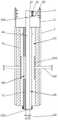
图2为本发明一种血管吻合器一实施方式中的主视结构示意图的剖视图;2 is a cross-sectional view of a schematic front view structure of an embodiment of a vascular stapler of the present invention;
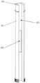
图3为本发明一种血管吻合器一实施方式中的主柱体的主视结构示意图的剖视图;3 is a cross-sectional view of a schematic front view structure of a main cylinder in an embodiment of a vascular stapler of the present invention;
图4为本发明一种血管吻合器一实施方式中的转柱的立体结构示意图;4 is a schematic three-dimensional structural diagram of a rotating column in an embodiment of a vascular stapler of the present invention;
图5为本发明一种血管吻合器一实施方式中的固定机构的立体结构示意图;5 is a schematic three-dimensional structural diagram of a fixing mechanism in an embodiment of a vascular stapler of the present invention;
图6为图5中A处的局部放大图;Fig. 6 is the partial enlarged view of A place in Fig. 5;
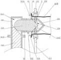
图7为本发明一种血管吻合器一实施方式中的固定机构的主视结构示意图的剖视图;7 is a cross-sectional view of a schematic front view of a fixing mechanism in an embodiment of a vascular stapler of the present invention;
图8为图7中B处的局部放大图;Fig. 8 is a partial enlarged view at B in Fig. 7;
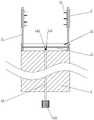
图9为本发明一种血管吻合器一实施方式中固定机构将血管断端固定在吻合环的针体上的结构示意图;FIG. 9 is a schematic structural diagram of fixing a broken end of a blood vessel on a needle body of an anastomotic ring by a fixing mechanism in an embodiment of a vascular stapler of the present invention;
图10为本发明一种血管吻合器一实施方式中的吻合部的主视结构示意图的剖视图;10 is a cross-sectional view of a schematic front view of the structure of an anastomotic portion in an embodiment of a vascular anastomotic device of the present invention;
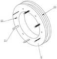
图11为本发明一种血管吻合器一实施方式中的吻合环的立体结构示意图;11 is a schematic three-dimensional structural diagram of an anastomotic ring in an embodiment of a vascular stapler of the present invention;
附图标记:Reference number:
吻合部1,卡置部11,支起柱111,U型扣112,滑动槽12,从动杆13,第一锥齿轮131,主动杆14,吻合旋钮141,第二锥齿轮142;The
吻合环2,针体21,插槽22,卡置槽23;
固定机构3,驱动组件31,操作管311,管腔3111,上限位圈3112,下限位圈3113,驱动柱312,驱动头313,抵柱3131,锥形头3132,校准柱头32,端头321,第一侧槽322,第一弹性件323,第二弹性件324,第二侧槽325,固定柱326,第三弹性件327,驱动腔328,抵片33,豁口331,固定刺332;
调位机构4,主柱体41,转孔411,移动槽412,推柱413,推板4131,限位块414,转柱42,侧容纳槽421,支块422,推入槽423。Positioning mechanism 4 ,
具体实施方式Detailed ways
为使本发明的上述目的、特征和优点能够更加明显易懂,下面结合附图对本发明的具体实施方式做详细的说明。在下面的描述中阐述了很多具体细节以便于充分理解本发明。但是本发明能够以很多不同于在此描述的其它方式来实施,本领域技术人员可以在不违背本发明内涵的情况下做类似改进,因此发明不受下面公开的具体实施的限制。In order to make the above objects, features and advantages of the present invention more clearly understood, the specific embodiments of the present invention will be described in detail below with reference to the accompanying drawings. In the following description, numerous specific details are set forth in order to provide a thorough understanding of the present invention. However, the present invention can be implemented in many other ways different from those described herein, and those skilled in the art can make similar improvements without departing from the connotation of the present invention, so the invention is not limited by the specific implementation disclosed below.
需要说明的是,当元件被称为“固定于”另一个元件,它可以直接在另一个元件上或者也可以存在居中的元件。当一个元件被认为是“连接”另一个元件,它可以是直接连接到另一个元件或者可能同时存在居中元件。本文所使用的术语“垂直的”、“水平的”、“左”、“右”以及类似的表述只是为了说明的目的,并不表示是唯一的实施方式。It should be noted that when an element is referred to as being "fixed to" another element, it can be directly on the other element or intervening elements may also be present. When an element is referred to as being "connected" to another element, it can be directly connected to the other element or intervening elements may also be present. The terms "vertical", "horizontal", "left", "right" and similar expressions used herein are for the purpose of illustration only and do not represent the only embodiment.
除非另有定义,本文所使用的所有的技术和科学术语与属于本发明的技术领域的技术人员通常理解的含义相同。本文中在本发明的说明书中所使用的术语只是为了描述具体的实施例的目的,不是旨在于限制本发明。Unless otherwise defined, all technical and scientific terms used herein have the same meaning as commonly understood by one of ordinary skill in the art to which this invention belongs. The terms used herein in the description of the present invention are for the purpose of describing specific embodiments only, and are not intended to limit the present invention.
如图1-11所示,本实施方式提供的一种血管吻合器,包括吻合部1,吻合环2,固定机构3和调位机构4。As shown in FIGS. 1-11 , a vascular stapler provided in this embodiment includes an
请参阅图1、图2和图10,吻合部1的顶部安装有两个卡置部11,卡置部11用于安装吻合环2,吻合部1用于驱动两个卡置部11彼此靠近或远离。Please refer to FIG. 1 , FIG. 2 and FIG. 10 , two clamping
需要注意的是,在将血管断端固定在吻合环2上之前,两个卡置部11应处于彼此远离的状态。It should be noted that, before the broken end of the blood vessel is fixed on the
如图10所示,在一实施方式中,吻合部1的顶部开设有滑动槽12,滑动槽12内横向设置有能够轴向转动的从动杆13。从动杆13的表面具有两个呈对称设置且旋向相反的螺纹段,且两螺纹段的衔接处安装有第一锥齿轮131。两个卡置部11的底部分别可滑动地安装于滑动槽12内并分别与两处螺纹段传动连接,转动从动杆13能够驱使两个卡置部11彼此靠近或远离。并且,吻合部1内安装有能够轴向转动的主动杆14。主动杆14的一端贯穿吻合部1的底部并设置有吻合旋钮141,便于在吻合部1的底部操作旋转主动杆14。主动杆14的另一端贯穿吻合部1的顶部并设置有第二锥齿轮142,第二锥齿轮142位于滑动槽12内并与第一锥齿轮131传动连接。As shown in FIG. 10 , in one embodiment, a sliding
在具体使用时,通过转动主动杆14即可驱使从动杆13转动,进而驱动两个卡置部11彼此靠近或远离,有利于方便在手术时进行控制。In specific use, the driven
在一实施方式中,卡置部11包括支起柱111和U型扣112。支起柱111可滑动地安装于滑动槽12内并向上延伸,支起柱111用于将U型扣112抬高支起,为固定机构3和调位机构4腾出操作空间。吻合环2能够直接卡入U型扣112的槽内或从槽内卸下,有利于吻合环2的快速安装和拆卸。为了进一步为固定机构3和调位机构4腾出操作空间,更进一步的,U型扣112安装于支起柱111的顶部并支出吻合部1的一侧。In one embodiment, the clamping
请参阅图1、图9和图11,吻合环2用于将两血管断端吻合连接,在具体使用时,需要将血管断端穿过吻合环2的内圈。吻合环2于每个卡置部11上可拆卸地各安装一个。具体的,如图11所示,吻合环2的外圈周向设置有卡置槽23,且吻合环2能够通过卡置槽23卡入U型扣112的槽内。两个吻合环2朝向彼此的一侧周向均布有多个针体21,针体21既用于血管断端的吻合,也用于固定血管断端,将血管断端的血管壁穿挂在各个针体21上即完成固定。且吻合环2上相邻的两个针体21之间均设置有插槽22,两个吻合环2之间通过将各个针体21插入插槽22中进行吻合连接,因此,在将两个吻合环2安装在U型扣112上时,需要将彼此的针体21分别对应对方的插槽22。Please refer to FIG. 1 , FIG. 9 and FIG. 11 , the
为了使针体21插入插槽22后连接更加牢固,具体的,针体21上可设置多个沿针体21长度方向排布的斜棘,且斜棘的朝向与针体21的插入方向相反,相应的,插槽22内设置有卡块,以防止针体21插入插槽22内后回退。In order to make the
请参阅图1、图2以及图5-图9,固定机构3包括驱动组件31和校准柱头32。Please refer to FIG. 1 , FIG. 2 and FIGS. 5 to 9 , the
校准柱头32用于对准各个吻合环2的中心并移向该中心,因此,校准柱头32的尺寸应小于吻合环2的内圈尺寸,以便进入吻合环2的内圈。校准柱头32的一端为端头321,端头321作为朝吻合环2中心移动的穿入端。优选的,端头321为圆锥状,以便于对准和进入吻合环2内圈。校准柱头32位于两个吻合环2之间。校准柱头32的外侧周向均布有多个抵片33,每个抵片33的首端均与校准柱头32铰接,抵片33用于将血管断端的内膜外翻。The
如图6所示,优选的,抵片33的数量为一个吻合环2上针体21和插槽22的数量之和,有利于使两个吻合环2上的针体21均能被抵片33对准。每个抵片33的末端均开设有豁口331,当校准柱头32移向吻合环2并展开抵片33时,各个针体21均能够通过对应的豁口331。为了避免抵片33外翻血管内膜时血管壁发生滑动移位,优选的,每个抵片33靠近端头321的一侧位于豁口331两侧的位置上均设置有固定刺332,在抵片33外翻并与血管内壁抵接时,固定刺332能够暂时穿刺血管壁进行临时固定,在将血管壁穿挂在针体21上后收回抵片33时即可取消固定,并且穿刺点与血管壁的固定点邻近,不会影响最终血管的吻合效果。As shown in FIG. 6 , preferably, the number of the
驱动组件31用于驱动所有抵片33同步转动,以使抵片33的末端能够靠近或远离端头321。The driving assembly 31 is used to drive all the
具体的,如图7和图8所示,驱动组件31包括操作管311、驱动柱312和驱动头313。操作管311的内部具有管腔3111。校准柱头32设置于操作管311的顶端一侧且端头321朝外,校准柱头32的内部具有与管腔3111连通的驱动腔328。Specifically, as shown in FIGS. 7 and 8 , the driving assembly 31 includes an
进一步的,校准柱头32对应每个抵片33的侧壁上均开设有第一侧槽322,第一侧槽322将驱动腔328与外界连通。每个抵片33分别与第一侧槽322靠近端头321的一端铰接并通过第一弹性件323与第一侧槽322内壁连接,第一弹性件323能够提供将抵片33末端推向驱动腔328的弹性力。驱动头313可滑动地安装于驱动腔328内且末端位于管腔3111内。驱动头313上对应每个抵片33周向均布有多个抵柱3131,各个抵柱3131分别位于第一侧槽322内且端部与抵片33抵接。驱动头313通过第二弹性件324与校准柱头32连接,第二弹性件324能够提供将驱动头313朝管腔3111方向移动的弹性力。优选的,为了使驱动头313滑动更加平稳,第二弹性件324设置有多个,且分别对应安装于各个抵柱3131与第一侧槽322的内壁之间。Further, a
驱动柱312可滑动地安装于管腔3111内且底端穿出操作管311。驱动柱312的顶端朝向校准柱头32的一侧呈倾斜斜面并与驱动头313的末端抵接。优选的,驱动头313靠近驱动柱312的一端为圆弧面,便于驱动柱312向内推动,同时操作管311的顶端封口,以防止驱动柱312的顶端穿出。The driving
在具体使用时,通过向内挤压驱动柱312即可驱使驱动头313向驱动腔328内移动,进而通过各个抵柱3131推动抵片33外翻血管内膜。待血管穿挂在针体21上后,向外拉出驱动柱312,驱动头313在第二弹性件324的弹性力作用下滑向管腔3111,抵片33将在第一弹性件323的弹性力作用下始终与抵柱3131抵接并内收。In specific use, the driving
其中,驱动柱312的底端可设置抽拉片,有利于向内挤压或向外拉出驱动柱312。Wherein, the bottom end of the
如图7-图9所示,在一实施方式中,校准柱头32位于第一侧槽322与端头321之间的侧壁上相对设置有两个第二侧槽325,两个第二侧槽325内均可滑动地安装有固定柱326,两个固定柱326之间连接有第三弹性件327,第三弹性件327能够提供将两个固定柱326拉向驱动腔328的弹性力。驱动头313靠近端头321的一端设置有锥形头3132,该锥形头3132的两侧面分别与两固定柱326靠近彼此的一端抵接。As shown in FIGS. 7-9 , in one embodiment, two
驱动头313向驱动腔328内移动时将驱使锥形头3132从两固定柱326之间将两固定柱326挤开,两固定柱326将受力向外滑动。在具体使用时,移动校准柱头32,使固定柱326的外端处于吻合环2的内圈范围内,再向内挤压驱动柱312,即可将血管壁固定于固定柱326与吻合环2的内壁之间,防止抵片33外翻血管内膜时血管整体发生移动导致固定失败。向外拉出驱动柱312能够立刻解除固定。When the driving
其中,第一弹性件323、第二弹性件324和第三弹性件327均可采用弹簧。Wherein, the first
请参阅图1-图5,调位机构4用于驱动校准柱头32在两个吻合环2之间移动,以使端头321能够分别对准两个吻合环2的中心并朝该中心移动。1-5, the positioning mechanism 4 is used to drive the
在一实施方式中,调位机构4包括主柱体41和转柱42,主柱体41安装于吻合部1位于U型扣112支出的一侧。主柱体41内设置有贯通其顶部和底部的转孔411,转孔411靠近两个U型扣112的两侧分别设置有移动槽412。转柱42可轴向转动地安装于转孔411内,具体的,转柱42上周向设置有转动圈,而转孔411内设置有与转动圈适配的转动槽。优选的,转柱42的底端穿出转孔411外并周向设置有防滑圈,便于在手术时旋转转柱42。转柱42的一侧开设有侧容纳槽421,操作管311可滑动地安装于侧容纳槽421内且两端穿出主柱体41,操作管311位于侧容纳槽421时,校准柱头32的端头321将朝向侧容纳槽421的侧面开口方向。优选的,操作管311的底端可设置抽拉片,有利于通过抽拉片滑动操作管311。In one embodiment, the positioning mechanism 4 includes a
当转柱42转动至侧容纳槽421与某一移动槽412连通时,操作管311可移动至移动槽412内,并使校准柱头32移向该侧的吻合环2。需要注意的是,当操作管311移动至移动槽412内时,校准柱头32的固定柱326将处于吻合环2的内圈范围内。When the
优选的,操作管311的外壁呈方形,且侧容纳槽421和移动槽412的内壁均能与操作管311的外壁紧密贴合,有利于防止操作管311移动时发生偏移。Preferably, the outer wall of the
在一实施方式中,两个移动槽412远离彼此的一侧分别贯穿安装有推柱413,每个推柱413的一端均位于主柱体41内并设置有推板4131,且每个推柱413的另一端均位于主柱体41外,两个推柱413均能沿靠近或远离彼此的方向滑动,转柱42远离侧容纳槽421的一侧对应推板4131设置有推入槽423。In one embodiment, push
在具体使用时,旋转转柱42以使侧容纳槽421对准任一移动槽412,通过推动两个推柱413即可将操作管311在侧容纳槽421与移动槽412之间移动。In specific use, the rotating
在一实施方式中,操作管311的底端设置有下限位圈3113且顶端位于校准柱头32下方的位置处设置有上限位圈3112,当下限位圈3113与转柱42抵接时校准柱头32与吻合环2处于同一高度,当上限位圈3112与转柱42抵接时校准柱头32处于U型扣112的下方。In one embodiment, the bottom end of the
优选的,主柱体41的顶部位于转孔411的两侧分别设置有限位块414,转柱42的顶部设置有支块422,转动转柱42能够使支块422分别与两个限位块414抵接,以使校准柱头32的端头321分别朝向两个吻合环2。有利于将侧容纳槽421与移动槽412快速对准。Preferably, the top of the
本发明提供的一种血管吻合器,在具体使用时,医生手持吻合部1或主柱体41将装置置于手术位置,滑动操作管311使下限位圈3113与转柱42抵接,以将校准柱头32移动至与吻合环2处于同一高度的位置;将一根血管的断端穿过其中一个吻合环2的内圈,旋转转柱42使侧容纳槽421与该侧的移动槽412对接;按压远离校准柱头32一侧的推柱413,使操作管311移动至移动槽412内,以使校准柱头32移向吻合环2并穿入血管内;向内推入驱动柱312以推动驱动头313向驱动腔328内移动,进而推动固定柱326对吻合环2内圈的血管壁进行挤压固定,同时抵柱3131推动抵片33外翻,抵片33抵住血管内膜外翻,并将血管壁穿挂固定在各个针体21上;向外拉出驱动柱312以使抵片33和固定柱326恢复原位;按压靠近校准柱头32一侧的推柱413,使操作管311移动至侧容纳槽421内;再次转动转柱42使侧容纳槽421与另一侧的移动槽412对接,再重复上述固定操作;完成两根血管断端在吻合环2上的固定后,将操作管311移动至侧容纳槽421内并滑动操作管311使上限位圈3112与转柱42抵接,以使校准柱头32位于支起柱111的高度范围内;旋转吻合旋钮141使两个卡置部11彼此靠近,两个吻合环2上的针体21插入对应的插槽22内直至完全贴合连接;将吻合环2从卡置部11上卸下,可用手术钳或镊子再次将两吻合环2夹紧,即完成两血管断端的吻合连接。For a vascular anastomosis device provided by the present invention, during specific use, the doctor holds the
本发明利用吻合部1中的传动机构控制两个卡置部11彼此靠近和远离,从远端进行控制,有利于避免在狭小的手术区域内进行吻合环2的连接操作,降低了吻合环2之间的连接难度,提高吻合效率;利用驱动组件31、校准柱头32和抵片33之间的组合联动,能够快速且同时地将各个位置的血管壁固定在吻合环2上,极大地提高了血管与吻合环2的固定效率,且各个抵片33同时外翻能够保证每处血管壁的牵拉外翻程度相同,提升了血管的吻合效果;利用抵片33上的豁口331和固定刺332结构以及固定柱326结构,能够在外翻血管壁时对血管进行有效固定,防止在固定过程中血管位置发生偏移;固定柱326对血管的固定和抵片33外翻血管内膜同时进行且一步到位,提高了手术效率;利用调位机构4驱动校准柱头32在两个吻合环2之间进行位置调换,进一步提高了手术效率和校准柱头32与吻合环2之间的连接精度。本发明能够极大程度地缩短手术时间,并且能够提高血管之间的吻合精密度,有利于患者的术后恢复,提高手术质量。The present invention uses the transmission mechanism in the
以上实施方式仅用以说明本发明的技术方案,而非对其限制;尽管参照前述各实施方式对本发明进行了详细的说明,本领域的普通技术人员应当理解:其依然可以对前述各实施方式所记载的技术方案进行修改,或者对其中部分或者全部技术特征进行等同替换;而这些修改或者替换,并不使相应技术方案的本质脱离本发明各实施方式技术方案的范围,其均应涵盖在本发明的权利要求和说明书的范围当中。The above embodiments are only used to illustrate the technical solutions of the present invention, but not to limit them; although the present invention has been described in detail with reference to the foregoing embodiments, those of ordinary skill in the art should understand that the foregoing embodiments can still be used for The recorded technical solutions are modified, or some or all of the technical features thereof are equivalently replaced; and these modifications or replacements do not make the essence of the corresponding technical solutions deviate from the scope of the technical solutions of the various embodiments of the present invention, which shall be included in the The invention is within the scope of the claims and description.
Claims (10)
Priority Applications (1)
| Application Number | Priority Date | Filing Date | Title |
|---|---|---|---|
| CN202210949437.4ACN115153707B (en) | 2022-08-09 | 2022-08-09 | A vascular anastomosis device |
Applications Claiming Priority (1)
| Application Number | Priority Date | Filing Date | Title |
|---|---|---|---|
| CN202210949437.4ACN115153707B (en) | 2022-08-09 | 2022-08-09 | A vascular anastomosis device |
Publications (2)
| Publication Number | Publication Date |
|---|---|
| CN115153707Atrue CN115153707A (en) | 2022-10-11 |
| CN115153707B CN115153707B (en) | 2025-09-30 |
Family
ID=83479210
Family Applications (1)
| Application Number | Title | Priority Date | Filing Date |
|---|---|---|---|
| CN202210949437.4AActiveCN115153707B (en) | 2022-08-09 | 2022-08-09 | A vascular anastomosis device |
Country Status (1)
| Country | Link |
|---|---|
| CN (1) | CN115153707B (en) |
Cited By (1)
| Publication number | Priority date | Publication date | Assignee | Title |
|---|---|---|---|---|
| CN119366993A (en)* | 2025-01-02 | 2025-01-28 | 华融科创生物科技(天津)有限公司 | Fixation device for vascular anastomosis |
Citations (11)
| Publication number | Priority date | Publication date | Assignee | Title |
|---|---|---|---|---|
| US20030167064A1 (en)* | 1999-09-01 | 2003-09-04 | Whayne James G. | Advanced anastomosis systems (II) |
| JP2003260062A (en)* | 2002-03-11 | 2003-09-16 | Terumo Corp | Vascular extroversion instrument |
| WO2014065232A1 (en)* | 2012-10-23 | 2014-05-01 | 学校法人久留米大学 | Blood vessel clamp device and blood vessel anastomosis method using same |
| US20150088172A1 (en)* | 2012-01-30 | 2015-03-26 | Kurume University | Vascular anastomosis device and vascular anastomosis method |
| CN213283157U (en)* | 2020-07-14 | 2021-05-28 | 华融科创生物科技(天津)有限公司 | Blood vessel anastomosis device with good anastomosis effect |
| CN113367755A (en)* | 2021-06-09 | 2021-09-10 | 华融科创生物科技(天津)有限公司 | Novel blood vessel anastomosis device |
| CN113967047A (en)* | 2021-11-16 | 2022-01-25 | 华融科创生物科技(天津)有限公司 | Blood vessel anastomosis device |
| CN113967046A (en)* | 2021-11-16 | 2022-01-25 | 华融科创生物科技(天津)有限公司 | Rope type blood vessel anastomosis device |
| CN113974741A (en)* | 2021-12-03 | 2022-01-28 | 杜玲娟 | Vascular anastomosis device for vascular surgery |
| CN114027905A (en)* | 2021-10-15 | 2022-02-11 | 浙江工业大学 | Needle ring method blood vessel anastomat with outward-turning blood vessel hanging ring function and anastomosis method |
| CN114795353A (en)* | 2022-05-23 | 2022-07-29 | 阜外华中心血管病医院 | High-efficient type operation anastomat for vascular surgery |
- 2022
- 2022-08-09CNCN202210949437.4Apatent/CN115153707B/enactiveActive
Patent Citations (11)
| Publication number | Priority date | Publication date | Assignee | Title |
|---|---|---|---|---|
| US20030167064A1 (en)* | 1999-09-01 | 2003-09-04 | Whayne James G. | Advanced anastomosis systems (II) |
| JP2003260062A (en)* | 2002-03-11 | 2003-09-16 | Terumo Corp | Vascular extroversion instrument |
| US20150088172A1 (en)* | 2012-01-30 | 2015-03-26 | Kurume University | Vascular anastomosis device and vascular anastomosis method |
| WO2014065232A1 (en)* | 2012-10-23 | 2014-05-01 | 学校法人久留米大学 | Blood vessel clamp device and blood vessel anastomosis method using same |
| CN213283157U (en)* | 2020-07-14 | 2021-05-28 | 华融科创生物科技(天津)有限公司 | Blood vessel anastomosis device with good anastomosis effect |
| CN113367755A (en)* | 2021-06-09 | 2021-09-10 | 华融科创生物科技(天津)有限公司 | Novel blood vessel anastomosis device |
| CN114027905A (en)* | 2021-10-15 | 2022-02-11 | 浙江工业大学 | Needle ring method blood vessel anastomat with outward-turning blood vessel hanging ring function and anastomosis method |
| CN113967047A (en)* | 2021-11-16 | 2022-01-25 | 华融科创生物科技(天津)有限公司 | Blood vessel anastomosis device |
| CN113967046A (en)* | 2021-11-16 | 2022-01-25 | 华融科创生物科技(天津)有限公司 | Rope type blood vessel anastomosis device |
| CN113974741A (en)* | 2021-12-03 | 2022-01-28 | 杜玲娟 | Vascular anastomosis device for vascular surgery |
| CN114795353A (en)* | 2022-05-23 | 2022-07-29 | 阜外华中心血管病医院 | High-efficient type operation anastomat for vascular surgery |
Cited By (2)
| Publication number | Priority date | Publication date | Assignee | Title |
|---|---|---|---|---|
| CN119366993A (en)* | 2025-01-02 | 2025-01-28 | 华融科创生物科技(天津)有限公司 | Fixation device for vascular anastomosis |
| CN119366993B (en)* | 2025-01-02 | 2025-03-18 | 华融科创生物科技(天津)有限公司 | Fixation device for vascular anastomosis |
Also Published As
| Publication number | Publication date |
|---|---|
| CN115153707B (en) | 2025-09-30 |
Similar Documents
| Publication | Publication Date | Title |
|---|---|---|
| US6811555B1 (en) | Method and apparatus for performing anastomosis with eversion of tissue edges and joining of exposed intima of the everted tissue | |
| US6551334B2 (en) | Externally directed anastomosis systems and externally positioned anastomosis fenestra cutting apparatus | |
| US6652542B2 (en) | External anastomosis operators and related systems for anastomosis | |
| US7901417B2 (en) | Systems for forming an anastomosis with an anvil and an apparatus having at least one guide | |
| US7220268B2 (en) | Methods for anastomosis of a graft vessel to a side of a receiving vessel | |
| US6248117B1 (en) | Anastomosis apparatus for use in intraluminally directed vascular anastomosis | |
| US20030078597A1 (en) | Intraluminally directed anvil apparatus and related methods and systems | |
| US20030032968A1 (en) | Method and device for urethral-vesicle anastomosis | |
| WO2001091628A2 (en) | Method and apparatus for performing end-to-end and end-to-side anastomosis with eversion of tissue edges | |
| JP2003526411A (en) | External introduction type anastomosis system and external positioning anastomosis window cutting device | |
| EP1211987A1 (en) | Method and apparatus for performing anastomosis | |
| CN115153707A (en) | a vascular stapler | |
| US20180271529A1 (en) | Device to aid in arterial microvascular anastomosis | |
| US20130110140A1 (en) | Anastomosis system | |
| CN113349860A (en) | Novel blood vessel anastomosis device | |
| CN215273049U (en) | Novel blood vessel anastomosis device | |
| CN113143368A (en) | Vascular anastomosis device | |
| CN113967046A (en) | Rope type blood vessel anastomosis device | |
| CN106821444A (en) | For the clamp device and apparatus for displaying of the Ni-based marmem tissue closure folder of titanium | |
| CN215273047U (en) | Novel blood vessel anastomosis device | |
| CN116327292A (en) | An eversion bladder urethral stapler | |
| CN115054305A (en) | Vascular anastomosis device for vascular surgery |
Legal Events
| Date | Code | Title | Description |
|---|---|---|---|
| PB01 | Publication | ||
| PB01 | Publication | ||
| SE01 | Entry into force of request for substantive examination | ||
| SE01 | Entry into force of request for substantive examination | ||
| GR01 | Patent grant |