CN115153700A - Disposable endoscope spiral continuous suture needle - Google Patents
Disposable endoscope spiral continuous suture needleDownload PDFInfo
- Publication number
- CN115153700A CN115153700ACN202210846746.9ACN202210846746ACN115153700ACN 115153700 ACN115153700 ACN 115153700ACN 202210846746 ACN202210846746 ACN 202210846746ACN 115153700 ACN115153700 ACN 115153700A
- Authority
- CN
- China
- Prior art keywords
- suture
- needle
- suture needle
- metal
- base body
- Prior art date
- Legal status (The legal status is an assumption and is not a legal conclusion. Google has not performed a legal analysis and makes no representation as to the accuracy of the status listed.)
- Granted
Links
- 239000002184metalSubstances0.000claimsabstractdescription32
- 229910052751metalInorganic materials0.000claimsabstractdescription32
- 238000001574biopsyMethods0.000claimsabstractdescription17
- 238000003032molecular dockingMethods0.000claimsdescription16
- 238000005452bendingMethods0.000claimsdescription3
- 239000007769metal materialSubstances0.000claimsdescription3
- 230000006978adaptationEffects0.000claims1
- 238000013461designMethods0.000abstractdescription5
- 208000002847Surgical WoundDiseases0.000abstractdescription3
- 210000004400mucous membraneAnatomy0.000abstractdescription3
- 210000004877mucosaAnatomy0.000description7
- 238000010586diagramMethods0.000description4
- 238000001839endoscopyMethods0.000description4
- 238000000034methodMethods0.000description3
- 239000004677NylonSubstances0.000description2
- 238000002674endoscopic surgeryMethods0.000description2
- 238000007689inspectionMethods0.000description2
- 238000002350laparotomyMethods0.000description2
- 229920001778nylonPolymers0.000description2
- 230000008569processEffects0.000description2
- 238000002271resectionMethods0.000description2
- RTAQQCXQSZGOHL-UHFFFAOYSA-NTitaniumChemical compound[Ti]RTAQQCXQSZGOHL-UHFFFAOYSA-N0.000description1
- 206010052428WoundDiseases0.000description1
- 208000027418Wounds and injuryDiseases0.000description1
- 210000000683abdominal cavityAnatomy0.000description1
- 230000003187abdominal effectEffects0.000description1
- 230000009471actionEffects0.000description1
- 239000000956alloySubstances0.000description1
- 229910045601alloyInorganic materials0.000description1
- 238000004891communicationMethods0.000description1
- 230000007812deficiencyEffects0.000description1
- 238000011161developmentMethods0.000description1
- 230000000694effectsEffects0.000description1
- 238000005516engineering processMethods0.000description1
- 239000000835fiberSubstances0.000description1
- 230000006870functionEffects0.000description1
- 238000011902gastrointestinal surgeryMethods0.000description1
- 210000001035gastrointestinal tractAnatomy0.000description1
- 238000010438heat treatmentMethods0.000description1
- 238000009434installationMethods0.000description1
- 230000010354integrationEffects0.000description1
- 230000003993interactionEffects0.000description1
- 210000001503jointAnatomy0.000description1
- 238000000465mouldingMethods0.000description1
- 230000035515penetrationEffects0.000description1
- 238000012545processingMethods0.000description1
- 210000002345respiratory systemAnatomy0.000description1
- 238000007789sealingMethods0.000description1
- 210000000115thoracic cavityAnatomy0.000description1
- 210000001519tissueAnatomy0.000description1
- 239000010936titaniumSubstances0.000description1
- 229910052719titaniumInorganic materials0.000description1
- 230000009466transformationEffects0.000description1
- 230000000472traumatic effectEffects0.000description1
- 210000001635urinary tractAnatomy0.000description1
Images


Classifications
- A—HUMAN NECESSITIES
- A61—MEDICAL OR VETERINARY SCIENCE; HYGIENE
- A61B—DIAGNOSIS; SURGERY; IDENTIFICATION
- A61B17/00—Surgical instruments, devices or methods
- A61B17/04—Surgical instruments, devices or methods for suturing wounds; Holders or packages for needles or suture materials
- A61B17/06—Needles ; Sutures; Needle-suture combinations; Holders or packages for needles or suture materials
- A61B17/06066—Needles, e.g. needle tip configurations
- A—HUMAN NECESSITIES
- A61—MEDICAL OR VETERINARY SCIENCE; HYGIENE
- A61B—DIAGNOSIS; SURGERY; IDENTIFICATION
- A61B10/00—Instruments for taking body samples for diagnostic purposes; Other methods or instruments for diagnosis, e.g. for vaccination diagnosis, sex determination or ovulation-period determination; Throat striking implements
- A61B10/02—Instruments for taking cell samples or for biopsy
- A61B10/04—Endoscopic instruments, e.g. catheter-type instruments
- A—HUMAN NECESSITIES
- A61—MEDICAL OR VETERINARY SCIENCE; HYGIENE
- A61B—DIAGNOSIS; SURGERY; IDENTIFICATION
- A61B10/00—Instruments for taking body samples for diagnostic purposes; Other methods or instruments for diagnosis, e.g. for vaccination diagnosis, sex determination or ovulation-period determination; Throat striking implements
- A61B10/02—Instruments for taking cell samples or for biopsy
- A61B10/06—Biopsy forceps, e.g. with cup-shaped jaws
- A—HUMAN NECESSITIES
- A61—MEDICAL OR VETERINARY SCIENCE; HYGIENE
- A61B—DIAGNOSIS; SURGERY; IDENTIFICATION
- A61B17/00—Surgical instruments, devices or methods
- A61B17/04—Surgical instruments, devices or methods for suturing wounds; Holders or packages for needles or suture materials
- A61B17/0469—Suturing instruments for use in minimally invasive surgery, e.g. endoscopic surgery
- A—HUMAN NECESSITIES
- A61—MEDICAL OR VETERINARY SCIENCE; HYGIENE
- A61B—DIAGNOSIS; SURGERY; IDENTIFICATION
- A61B17/00—Surgical instruments, devices or methods
- A61B17/04—Surgical instruments, devices or methods for suturing wounds; Holders or packages for needles or suture materials
- A61B17/0491—Sewing machines for surgery
- A—HUMAN NECESSITIES
- A61—MEDICAL OR VETERINARY SCIENCE; HYGIENE
- A61B—DIAGNOSIS; SURGERY; IDENTIFICATION
- A61B17/00—Surgical instruments, devices or methods
- A61B2017/00831—Material properties
- A61B2017/00867—Material properties shape memory effect
- A—HUMAN NECESSITIES
- A61—MEDICAL OR VETERINARY SCIENCE; HYGIENE
- A61B—DIAGNOSIS; SURGERY; IDENTIFICATION
- A61B17/00—Surgical instruments, devices or methods
- A61B17/04—Surgical instruments, devices or methods for suturing wounds; Holders or packages for needles or suture materials
- A61B17/06—Needles ; Sutures; Needle-suture combinations; Holders or packages for needles or suture materials
- A61B17/06066—Needles, e.g. needle tip configurations
- A61B2017/06076—Needles, e.g. needle tip configurations helically or spirally coiled
- Y—GENERAL TAGGING OF NEW TECHNOLOGICAL DEVELOPMENTS; GENERAL TAGGING OF CROSS-SECTIONAL TECHNOLOGIES SPANNING OVER SEVERAL SECTIONS OF THE IPC; TECHNICAL SUBJECTS COVERED BY FORMER USPC CROSS-REFERENCE ART COLLECTIONS [XRACs] AND DIGESTS
- Y02—TECHNOLOGIES OR APPLICATIONS FOR MITIGATION OR ADAPTATION AGAINST CLIMATE CHANGE
- Y02A—TECHNOLOGIES FOR ADAPTATION TO CLIMATE CHANGE
- Y02A50/00—TECHNOLOGIES FOR ADAPTATION TO CLIMATE CHANGE in human health protection, e.g. against extreme weather
- Y02A50/30—Against vector-borne diseases, e.g. mosquito-borne, fly-borne, tick-borne or waterborne diseases whose impact is exacerbated by climate change
Landscapes
- Health & Medical Sciences (AREA)
- Life Sciences & Earth Sciences (AREA)
- Surgery (AREA)
- General Health & Medical Sciences (AREA)
- Molecular Biology (AREA)
- Veterinary Medicine (AREA)
- Engineering & Computer Science (AREA)
- Biomedical Technology (AREA)
- Heart & Thoracic Surgery (AREA)
- Medical Informatics (AREA)
- Public Health (AREA)
- Animal Behavior & Ethology (AREA)
- Nuclear Medicine, Radiotherapy & Molecular Imaging (AREA)
- Pathology (AREA)
- Radiology & Medical Imaging (AREA)
- Biodiversity & Conservation Biology (AREA)
- Surgical Instruments (AREA)
Abstract
Translated fromChinese
Description
Translated fromChinese技术领域technical field
本发明涉及内窥镜手术工具技术领域,尤其是一种一次性内窥镜螺旋形连续缝合针。The invention relates to the technical field of endoscopic surgical tools, in particular to a disposable endoscopic spiral continuous suture needle.
背景技术Background technique
内窥镜术(endoscopy),应用可送入人体腔、道内的窥镜在直观下进行检查及治疗的技术。检查与外界相通的腔道(如消化道、呼吸道、泌尿道等),可直接将内窥镜插入,这称为无创伤性内窥镜检查术;检查密闭的体腔(如胸腔、腹腔、关节腔等),需通过切口将内窥镜送入,这称为创伤性内窥镜术。在内窥镜检查的同时,若使用各种配件,尚可进行治疗。Endoscopy is a technology that uses endoscopes that can be sent into human cavities and tracts to perform inspection and treatment under direct inspection. Check the cavities that communicate with the outside world (such as digestive tract, respiratory tract, urinary tract, etc.), and the endoscope can be inserted directly, which is called non-invasive endoscopy; check closed body cavities (such as chest cavity, abdominal cavity, joints, etc.) cavity, etc.), the endoscope needs to be introduced through an incision, which is called traumatic endoscopy. At the same time as endoscopy, treatment can still be performed if various accessories are used.
随着医疗水平的发展,内窥镜手术日益的增多,其中针对肠胃手术的术口也由黏膜层切除发展至5层切除,术口的大小也有小于1厘米发展到3厘米左右。而这种术口缝合,在内窥镜手术下,目前的钛夹封合术不利于全层连续缝合,当术口大于2厘米,缝合的难度非常大,甚至要借助尼龙绳、尼龙圈等辅助缝合。如果内镜下中无法缝合,就要改为外科开腹手术加缝合术,这样会加重了患者的手术经济负担及手术风险。With the development of medical level, the number of endoscopic surgery is increasing day by day. Among them, the surgical opening for gastrointestinal surgery has also developed from mucosal layer resection to 5-layer resection, and the size of the surgical opening has also developed from less than 1 cm to about 3 cm. For this kind of suture, under endoscopic surgery, the current titanium clip sealing is not conducive to full-thickness continuous suture. When the incision is larger than 2 cm, the suture is very difficult, and even nylon ropes, nylon loops, etc. are needed. Auxiliary suture. If the suture cannot be sutured under the endoscope, surgical laparotomy plus suture should be used, which will increase the economic burden and surgical risk of the patient.
发明内容SUMMARY OF THE INVENTION
针对上述现有技术中存在的不足,本发明的目的在于提供一种一次性内窥镜螺旋形连续缝合针。In view of the above-mentioned deficiencies in the prior art, the purpose of the present invention is to provide a disposable endoscope spiral continuous suture needle.
为了实现上述目的,本发明采用如下技术方案:In order to achieve the above object, the present invention adopts the following technical solutions:
一种一次性内窥镜螺旋形连续缝合针,包括基体、金属缝合线和缝合针,所述金属缝合线整体呈螺旋状,所述金属缝合线包括收拢部和缝合部,所述收拢部的直径保持一致,所述缝合部的端口呈喇叭状向外延展,所述收拢部一端与缝合部连接为一体,使所述收拢部与缝合部保持连贯,所述收拢部的另一端与基体固定连接,所述基体设置有可供活检钳夹持的夹持部,所述缝合部的端头处可拆卸式安装有缝合针。A disposable endoscope spiral continuous suture needle, comprising a base body, a metal suture thread and a suture needle, the metal suture thread is in a spiral shape as a whole, the metal suture thread includes a constriction part and a suture part, and the condensed part has a suture. The diameter of the suture is kept the same, the port of the suture extends outward in a trumpet shape, and one end of the fold is connected to the suture as a whole, so that the fold and the suture remain continuous, and the other end of the fold is fixed to the base connected, the base body is provided with a clamping part that can be clamped by the biopsy forceps, and a suture needle is detachably installed at the end of the suture part.
优选地,所述缝合部位于端头处设置有用于与缝合针对接的接壤部,所述接壤部设置对接端口,所述对接端口的端口处开设有夹持臂,所述夹持臂为记忆金属,所述夹持臂的内侧面设置有一插销,所述缝合针的尾部开设有一个针孔并插设于对接端口内,所述插销插设于针孔内,在接壤部受热之后,其夹持臂向外展开,使所述插销脱离针孔,从而满足缝合针的拆除。Preferably, the suture portion is provided with a border portion for connecting with the suture needle at the end, the border portion is provided with a docking port, and the port of the docking port is provided with a clamping arm, and the clamping arm is a memory Metal, the inner side of the clamping arm is provided with a pin, the tail of the suture needle is provided with a pin hole and inserted into the docking port, the pin is inserted in the pin hole, and after the border portion is heated, its The gripping arms are extended outwards to disengage the pins from the needle holes, thereby satisfying the removal of the suture needle.
优选地,所述对接端口的内腔形状与缝合针尾部形状相对应。Preferably, the shape of the lumen of the docking port corresponds to the shape of the tail of the suture needle.
优选地,所述缝合针尾部纵向中央设置有限位槽,所述夹持臂上设置有与限位槽对应的凸起栓,以防止针头在穿刺时左右摇摆,加强针头与螺旋部的整体运动一致性。Preferably, a limiting groove is provided in the longitudinal center of the tail of the suture needle, and a raised pin corresponding to the limiting groove is provided on the clamping arm, so as to prevent the needle from swinging left and right during puncturing, and enhance the overall movement of the needle and the helical portion. consistency.
优选地,所述缝合针为弯曲状,且所述金属缝合针的弯曲角度与缝合线的螺旋角度相互适配。Preferably, the suture needle is curved, and the bending angle of the metal suture needle and the helix angle of the suture thread match each other.
优选地,所述接壤部、夹持臂以及金属缝合线均为一体成型,且均为记忆金属材质制成。Preferably, the border portion, the clamping arm and the metal suture are all integrally formed and made of memory metal material.
优选地,所述基体位于夹持部的纵向中央凹陷形成有避让槽。Preferably, the base body is located in the longitudinal center of the clamping portion and is recessed to form an escape groove.
由于采用了上述方案,本发明利用金属缝合线的螺旋状连续缝合,而且巧妙的宝塔型收缩设计,利用喇叭状的缝合部去满足大开口的拉拢,并由收拢部闭合,从而使术口两边黏膜由拉拢再到逐渐靠拢,将张力较大的手术伤口减张靠拢。并且,在基于记忆金属受热形变的原理上,使缝合针可以轻松脱离针头,达到可拆卸针头。Due to the adoption of the above scheme, the present invention utilizes the spiral continuous suture of the metal suture, and the ingenious pagoda-shaped shrinkage design uses the trumpet-shaped suture to meet the pulling of the large opening, and is closed by the folded portion, so that both sides of the surgical opening are closed. The mucous membranes are drawn together and then gradually drawn together, reducing the tension of the surgical wound with greater tension and moving closer. Moreover, based on the principle of memory metal thermal deformation, the suture needle can be easily detached from the needle head to achieve a detachable needle head.
附图说明Description of drawings
图1是本发明实施例的结构原理示意图。FIG. 1 is a schematic diagram of the structural principle of an embodiment of the present invention.
图2是本发明实施例的对接端口处的结构示意图。FIG. 2 is a schematic structural diagram of a docking port according to an embodiment of the present invention.
图3是本发明实施例的缝合使用时的示意图。FIG. 3 is a schematic diagram of the suture of the embodiment of the present invention when used.
图4是本发明实施例的拆线操作的示意图。FIG. 4 is a schematic diagram of a stitch removal operation according to an embodiment of the present invention.
具体实施方式Detailed ways
为了使本发明的目的、技术方案及优点更加清楚明白,以下结合附图及实施例,对本发明进一步详细说明。应当理解,此处所描述的具体实施例仅仅用以解释本发明,并不用于限定本发明。In order to make the objectives, technical solutions and advantages of the present invention clearer, the present invention will be further described in detail below with reference to the accompanying drawings and embodiments. It should be understood that the specific embodiments described herein are only used to explain the present invention, but not to limit the present invention.
在本发明的描述中,需要理解的是,术语“中心”、“纵向”、“横向”、“长度”、“宽度”、“厚度”、“上”、“下”、“前”、“后”、“左”、“右”、“竖直”、“水平”、“顶”、“底”、“内”、“外”、“顺时针”、“逆时针”等指示的方位或位置关系为基于附图所示的方位或位置关系,仅是为了便于描述本发明和简化描述,而不是指示或暗示所指的装置或元件必须具有特定的方位、以特定的方位构造和操作,因此不能理解为对本发明的限制。此外,术语“第一”、“第二”仅用于描述目的,而不能理解为指示或暗示相对重要性或者隐含指明所指示的技术特征的数量。由此,限定有“第一”、“第二”的特征可以明示或者隐含地包括一个或者更多个所述特征。在本发明的描述中,“多个”的含义是两个或两个以上,除非另有明确具体的限定。In the description of the present invention, it should be understood that the terms "center", "longitudinal", "lateral", "length", "width", "thickness", "upper", "lower", "front", " rear, left, right, vertical, horizontal, top, bottom, inside, outside, clockwise, counterclockwise, etc., or The positional relationship is based on the orientation or positional relationship shown in the accompanying drawings, which is only for the convenience of describing the present invention and simplifying the description, rather than indicating or implying that the referred device or element must have a specific orientation, be constructed and operated in a specific orientation, Therefore, it should not be construed as a limitation of the present invention. In addition, the terms "first" and "second" are only used for descriptive purposes, and should not be construed as indicating or implying relative importance or implying the number of indicated technical features. Thus, features defined as "first", "second" may expressly or implicitly include one or more of said features. In the description of the present invention, "plurality" means two or more, unless otherwise expressly and specifically defined.
在本发明的描述中,需要说明的是,除非另有明确的规定和限定,术语“安装”、“相连”、“连接”应做广义理解,例如,可以是固定连接,也可以是可拆卸连接,或一体地连接。可以是机械连接,也可以是电连接。可以是直接相连,也可以通过中间媒介间接相连,可以是两个元件内部的连通或两个元件的相互作用关系。对于本领域的普通技术人员而言,可以根据具体情况理解上述术语在本发明中的具体含义。In the description of the present invention, it should be noted that the terms "installed", "connected" and "connected" should be understood in a broad sense, unless otherwise expressly specified and limited, for example, it may be a fixed connection or a detachable connection connected, or integrally connected. It can be a mechanical connection or an electrical connection. It can be directly connected, or indirectly connected through an intermediate medium, and it can be the internal communication between two elements or the interaction relationship between the two elements. For those of ordinary skill in the art, the specific meanings of the above terms in the present invention can be understood according to specific situations.
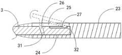
如图1至图4所示,本实施例提供的一种一次性内窥镜螺旋形连续缝合针,包括基体1、金属缝合线2和缝合针3,所述金属缝合线2整体呈螺旋状,所述金属缝合线2包括收拢部21和缝合部22,所述收拢部21的直径保持一致,所述缝合部22的端口呈喇叭状向外延展,所述收拢部21一端与缝合部22连接为一体,使所述收拢部21与缝合部22保持连贯,所述收拢部21的另一端与基体1固定连接,所述基体1设置有可供活检钳夹持的夹持部11,所述缝合部22的端头处可拆卸式安装有缝合针3。As shown in FIGS. 1 to 4 , a disposable endoscope spiral continuous suture needle provided in this embodiment includes a base body 1 , a
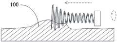
本实施例主要是利用金属缝合线2的螺旋状连续缝合,而且巧妙的宝塔型收缩设计,利用喇叭状的缝合部22去满足大开口的拉拢,并由收拢部21闭合,从而使术口两边黏膜100由拉拢再到逐渐靠拢,将张力较大的手术伤口减张靠拢。这样便可以针对一些相对较大的术口,也可以进行相关的内窥镜缝合,避免外科开腹手术。In this embodiment, the spiral continuous suture of the
具体操作时,由活检钳夹住基体的夹持部11,通过内窥镜的活检通道将整体进行推送到术口处,使缝合针3探出活检通道,并使缝合针3的针头接触到需要缝合黏膜100。随后,便通过手动转动活检钳,使活检钳顺时针转动之后,将力作用于基体上,使与基体1固定连接的金属缝合线2也随之进行旋转,故在旋转的过程中,缝合针3便会穿入黏膜100,随着继续旋转,其中因为缝合部22呈喇叭状,其端口处的直径相比整体的直径来说更大,所以缝合针3便会在喇叭状的缝合部22的带动下,穿入到另一边的黏膜100内,然后在穿出,满足两个黏膜100之间的跨度缝合。而螺旋状的设计,也将使得缝合针3回转,从而来达到在两个黏膜100之间反复穿设。在反复的旋转后,金属缝合线2便会逐步的穿入术口的黏膜100内,而根据收拢部21(收拢部的具体直径:需满足配套胃肠镜≤3.4mm,配套支气管镜和纤维鼻咽镜≤1.2mm,腹腔镜、关节镜及宫腔镜≤4.5mm,根据所配套的内窥镜活检孔道或腹腔镜腹部皮肤孔道所定,缝合部22的直径较收拢部大1-2mm,使其可以顺利通过内窥镜的活检孔道。)的直径缩小,便会将穿入到此处的黏膜100进行收拢,从而来达到术口缝合的作用。而收拢部21的长度,则根据术口长度而定,需要满足,收拢部21的长度大于术口的长度。当将术口缝合之后,则停止旋转,活检钳脱离夹持,然后将缝合针拆除。使金属缝合线2滞留于术口处,保持术口的收拢,等待术口愈合之后,则拆除金属缝合线2便可。而当需要进行拆线时,则再次由内窥镜进入人体内,并达到金属缝合术口处,用活检钳夹住夹持部11并逆时针旋转,同时向后拉基体1,使螺旋形的缝合部22慢慢退出已经愈合的术口,随后完成拆线步骤,如图4所示。During the specific operation, the
针对缝合针头3的拆除,是基于记忆金属(采用的是深圳市翔泰记忆新材料有限公司TINI02型医用记忆金属,其性能为:小于30°C时是一种外形状态,当>50°C时是一种外形状态。当完成缝合并要拆除缝合针头时,仅需要用热活检钳夹住其顶部即可。)受热形变的原理上,使医用合金(强度大且无变形)制成的缝合针3可以轻松脱离针头,达到可拆卸针头。The removal of the
具体结构如下:即所述缝合部22位于端头处设置有用于与缝合针3对接的接壤部23,所述接壤部23设置对接端口24,所述对接端口24的端口处开设有夹持臂25,所述夹持臂25为记忆金属,所述夹持臂25的内侧面设置有一插销26,所述缝合针3的尾部开设有一个针孔31并插设于对接端口24内,所述插销26插设于针孔31内,在接壤部23受热之后,其夹持臂25向外展开,使所述插销26脱离针孔31,从而满足缝合针3的拆除。故安装结构,便是采用对接端口24进行对缝合针3尾部的套装,达到初步对装,然后在通过夹持臂25闭合之后,插销26插入与缝合针3的针孔31之内,从而避免缝合针3的抽离,这样便达到锁固。而当需要将缝合针3进行拆除时,则需要通过热活检钳夹持接壤部23处,通过热活检钳的加热,使夹持臂25受热形变,形变方向是向外展开,而一旦夹持臂展开之后,插销26便会脱离缝合针3的针孔31,这样,在外力的作用下,缝合针3便可以抽离对接端口24。The specific structure is as follows: that is, the
进一步,本实施例的所述对接端口24的内腔形状与缝合针3尾部形状相对应,而缝合针3尾部的形状优选为棱柱体,这样可以避免自转。且针头为三菱锥或圆锥体,适应不同硬度及柔韧性的组织表面。Further, the shape of the inner cavity of the
进一步,本实施例的缝合针3尾部纵向中央设置有限位槽32,所述夹持臂25上设置有与限位槽32对应的凸起栓27。在限位槽32与凸起栓27在并拢时可以完全重合,其作用为防治穿刺针摆动,加强缝合针3与缝合部22一体化的强度。Further, a limiting
进一步,针对本实施例的所述缝合针3的形状,则设计成弯曲状,且所述缝合针3的弯曲角度与金属缝合线2的螺旋角度相互适配,这样便可以在旋转穿线时,可以保持的更加顺畅。Further, the shape of the
进一步,本实施例针对所述接壤部23、夹持臂25以及金属缝合线2其均为一体成型,且均为记忆金属材质制成。这样便会满足一体成型,便于工厂加工。Further, in this embodiment, the
进一步,为便于活检钳的夹持,故本实施例的所述基体1位于夹持部11的纵向中央凹陷形成有避让槽12,通过避让槽12的设计,可以让夹持部11更加凸出,便于选定和夹持。Further, in order to facilitate the clamping of the biopsy forceps, the base body 1 of the present embodiment is located in the longitudinal center of the clamping
以上仅为本发明的优选实施例,并非因此限制本发明的专利范围,凡是利用本发明说明书及附图内容所作的等效结构或等效流程变换,或直接或间接运用在其他相关的技术领域,均同理包括在本发明的专利保护范围内。The above are only preferred embodiments of the present invention, and are not intended to limit the scope of the present invention. Any equivalent structure or equivalent process transformation made by using the contents of the description and drawings of the present invention, or directly or indirectly applied in other related technical fields , are similarly included in the scope of patent protection of the present invention.
Claims (7)
Translated fromChinesePriority Applications (1)
| Application Number | Priority Date | Filing Date | Title |
|---|---|---|---|
| CN202210846746.9ACN115153700B (en) | 2022-07-19 | 2022-07-19 | Disposable endoscope spiral continuous suture needle |
Applications Claiming Priority (1)
| Application Number | Priority Date | Filing Date | Title |
|---|---|---|---|
| CN202210846746.9ACN115153700B (en) | 2022-07-19 | 2022-07-19 | Disposable endoscope spiral continuous suture needle |
Publications (2)
| Publication Number | Publication Date |
|---|---|
| CN115153700Atrue CN115153700A (en) | 2022-10-11 |
| CN115153700B CN115153700B (en) | 2023-09-01 |
Family
ID=83495630
Family Applications (1)
| Application Number | Title | Priority Date | Filing Date |
|---|---|---|---|
| CN202210846746.9AActiveCN115153700B (en) | 2022-07-19 | 2022-07-19 | Disposable endoscope spiral continuous suture needle |
Country Status (1)
| Country | Link |
|---|---|
| CN (1) | CN115153700B (en) |
Citations (9)
| Publication number | Priority date | Publication date | Assignee | Title |
|---|---|---|---|---|
| US5454834A (en)* | 1992-03-12 | 1995-10-03 | Richard Wolf Gmbh | Surgical suture material |
| WO1999062406A2 (en)* | 1998-06-03 | 1999-12-09 | Coalescent Surgical, Inc. | Tissue connector apparatus and methods |
| US20090216268A1 (en)* | 2008-02-21 | 2009-08-27 | Panter Gideon G | Suture and suturing technique for facilitating knotting |
| CN101541250A (en)* | 2006-10-05 | 2009-09-23 | 托马斯·纳普 | Shape memory wire for suture treatment |
| CN104873237A (en)* | 2010-06-11 | 2015-09-02 | 伊西康有限责任公司 | Suture Delivery Tools For Endoscopic And Robot-assisted Surgery And Methods |
| CN209611221U (en)* | 2018-11-20 | 2019-11-12 | 中国医学科学院北京协和医院 | An integrated surgical suture |
| CN211300134U (en)* | 2019-07-08 | 2020-08-21 | 上海康德莱医疗器械股份有限公司 | a suture |
| CN111759382A (en)* | 2020-07-29 | 2020-10-13 | 苏州明镜医疗科技有限公司 | A kind of suturing device for surgical operation and suturing method thereof |
| CN216294157U (en)* | 2021-08-28 | 2022-04-15 | 嘉兴市第一医院 | Suturing device for digestive endoscopy |
- 2022
- 2022-07-19CNCN202210846746.9Apatent/CN115153700B/enactiveActive
Patent Citations (9)
| Publication number | Priority date | Publication date | Assignee | Title |
|---|---|---|---|---|
| US5454834A (en)* | 1992-03-12 | 1995-10-03 | Richard Wolf Gmbh | Surgical suture material |
| WO1999062406A2 (en)* | 1998-06-03 | 1999-12-09 | Coalescent Surgical, Inc. | Tissue connector apparatus and methods |
| CN101541250A (en)* | 2006-10-05 | 2009-09-23 | 托马斯·纳普 | Shape memory wire for suture treatment |
| US20090216268A1 (en)* | 2008-02-21 | 2009-08-27 | Panter Gideon G | Suture and suturing technique for facilitating knotting |
| CN104873237A (en)* | 2010-06-11 | 2015-09-02 | 伊西康有限责任公司 | Suture Delivery Tools For Endoscopic And Robot-assisted Surgery And Methods |
| CN209611221U (en)* | 2018-11-20 | 2019-11-12 | 中国医学科学院北京协和医院 | An integrated surgical suture |
| CN211300134U (en)* | 2019-07-08 | 2020-08-21 | 上海康德莱医疗器械股份有限公司 | a suture |
| CN111759382A (en)* | 2020-07-29 | 2020-10-13 | 苏州明镜医疗科技有限公司 | A kind of suturing device for surgical operation and suturing method thereof |
| CN216294157U (en)* | 2021-08-28 | 2022-04-15 | 嘉兴市第一医院 | Suturing device for digestive endoscopy |
Also Published As
| Publication number | Publication date |
|---|---|
| CN115153700B (en) | 2023-09-01 |
Similar Documents
| Publication | Publication Date | Title |
|---|---|---|
| US7731727B2 (en) | Medical instrument to place a pursestring suture, open a hole and pass a guidewire | |
| CN215306369U (en) | Anchoring needle type suture clip device for suture under digestive endoscopy | |
| US20130324795A1 (en) | Three-dimensional retractor | |
| CN108433763B (en) | Magnetic controlled intracavitary tissue retractor | |
| WO2020248807A1 (en) | Endoluminal surgery instrument | |
| CN110251186A (en) | A chuck structure of tissue clip for endoscope | |
| WO2021184969A1 (en) | Endoscope channel suture clip | |
| JP5372301B1 (en) | Medical port | |
| CN216294157U (en) | Suturing device for digestive endoscopy | |
| CN209074718U (en) | Intracavitary traction device | |
| CN113081110A (en) | Urethral anastomat capable of quickly breaking line | |
| CN115153700A (en) | Disposable endoscope spiral continuous suture needle | |
| CN205885475U (en) | Drag hook is sewed up to peritoneoscope | |
| CN214073432U (en) | Improve surface of a wound suturing device under scope | |
| JP2000023989A (en) | Miniature loop retractor | |
| CN115944346A (en) | Clamp instrument | |
| CN109984810A (en) | A kind of puncture core assembly and the puncture outfit with it | |
| CN215605979U (en) | Suturing device convenient for gastrointestinal endoscope | |
| CN201418758Y (en) | Laparoscopic minimally invasive surgery stapler | |
| CN209332147U (en) | A kind of sewing needle for laparoscopic surgery | |
| CN113558688A (en) | Novel automatic stitching instrument for inverted barbed wire in endoscope | |
| CN222487469U (en) | A medical fishbone wire for lifting and pulling | |
| CN221750606U (en) | Endoscopic surgery suspension device | |
| CN220572217U (en) | Rotary far-end cap | |
| CN111388068A (en) | Uterine manipulator and uterine fixing method in laparoscopic surgery |
Legal Events
| Date | Code | Title | Description |
|---|---|---|---|
| PB01 | Publication | ||
| PB01 | Publication | ||
| SE01 | Entry into force of request for substantive examination | ||
| SE01 | Entry into force of request for substantive examination | ||
| GR01 | Patent grant | ||
| GR01 | Patent grant |