CN115153675A - Asymmetric rolling joint device for surgical instruments - Google Patents
Asymmetric rolling joint device for surgical instrumentsDownload PDFInfo
- Publication number
- CN115153675A CN115153675ACN202110954625.1ACN202110954625ACN115153675ACN 115153675 ACN115153675 ACN 115153675ACN 202110954625 ACN202110954625 ACN 202110954625ACN 115153675 ACN115153675 ACN 115153675A
- Authority
- CN
- China
- Prior art keywords
- radius
- rolling surface
- rolling
- hole
- surgical instrument
- Prior art date
- Legal status (The legal status is an assumption and is not a legal conclusion. Google has not performed a legal analysis and makes no representation as to the accuracy of the status listed.)
- Pending
Links
- 238000005096rolling processMethods0.000titleclaimsabstractdescription200
- 230000015572biosynthetic processEffects0.000claimsdescription28
- 238000000034methodMethods0.000claimsdescription5
- 238000010586diagramMethods0.000description11
- 238000005452bendingMethods0.000description4
- 238000005259measurementMethods0.000description4
- 230000003247decreasing effectEffects0.000description2
- 229940104181polyflexDrugs0.000description2
- 230000000694effectsEffects0.000description1
- 238000004519manufacturing processMethods0.000description1
- 238000012986modificationMethods0.000description1
- 230000004048modificationEffects0.000description1
- 210000000056organAnatomy0.000description1
- 230000009466transformationEffects0.000description1
Images


Classifications
- A—HUMAN NECESSITIES
- A61—MEDICAL OR VETERINARY SCIENCE; HYGIENE
- A61B—DIAGNOSIS; SURGERY; IDENTIFICATION
- A61B17/00—Surgical instruments, devices or methods
- A61B17/28—Surgical forceps
- A61B17/29—Forceps for use in minimally invasive surgery
- A—HUMAN NECESSITIES
- A61—MEDICAL OR VETERINARY SCIENCE; HYGIENE
- A61B—DIAGNOSIS; SURGERY; IDENTIFICATION
- A61B17/00—Surgical instruments, devices or methods
- A61B17/00234—Surgical instruments, devices or methods for minimally invasive surgery
- A—HUMAN NECESSITIES
- A61—MEDICAL OR VETERINARY SCIENCE; HYGIENE
- A61B—DIAGNOSIS; SURGERY; IDENTIFICATION
- A61B34/00—Computer-aided surgery; Manipulators or robots specially adapted for use in surgery
- A61B34/30—Surgical robots
- A—HUMAN NECESSITIES
- A61—MEDICAL OR VETERINARY SCIENCE; HYGIENE
- A61B—DIAGNOSIS; SURGERY; IDENTIFICATION
- A61B34/00—Computer-aided surgery; Manipulators or robots specially adapted for use in surgery
- A61B34/70—Manipulators specially adapted for use in surgery
- A61B34/71—Manipulators operated by drive cable mechanisms
- F—MECHANICAL ENGINEERING; LIGHTING; HEATING; WEAPONS; BLASTING
- F16—ENGINEERING ELEMENTS AND UNITS; GENERAL MEASURES FOR PRODUCING AND MAINTAINING EFFECTIVE FUNCTIONING OF MACHINES OR INSTALLATIONS; THERMAL INSULATION IN GENERAL
- F16C—SHAFTS; FLEXIBLE SHAFTS; ELEMENTS OR CRANKSHAFT MECHANISMS; ROTARY BODIES OTHER THAN GEARING ELEMENTS; BEARINGS
- F16C11/00—Pivots; Pivotal connections
- F16C11/04—Pivotal connections
- A—HUMAN NECESSITIES
- A61—MEDICAL OR VETERINARY SCIENCE; HYGIENE
- A61B—DIAGNOSIS; SURGERY; IDENTIFICATION
- A61B17/00—Surgical instruments, devices or methods
- A61B17/00234—Surgical instruments, devices or methods for minimally invasive surgery
- A61B2017/00292—Surgical instruments, devices or methods for minimally invasive surgery mounted on or guided by flexible, e.g. catheter-like, means
- A61B2017/003—Steerable
- A61B2017/00305—Constructional details of the flexible means
- A61B2017/00314—Separate linked members
- A—HUMAN NECESSITIES
- A61—MEDICAL OR VETERINARY SCIENCE; HYGIENE
- A61B—DIAGNOSIS; SURGERY; IDENTIFICATION
- A61B17/00—Surgical instruments, devices or methods
- A61B17/00234—Surgical instruments, devices or methods for minimally invasive surgery
- A61B2017/00292—Surgical instruments, devices or methods for minimally invasive surgery mounted on or guided by flexible, e.g. catheter-like, means
- A61B2017/003—Steerable
- A61B2017/00318—Steering mechanisms
- A61B2017/00323—Cables or rods
- A—HUMAN NECESSITIES
- A61—MEDICAL OR VETERINARY SCIENCE; HYGIENE
- A61B—DIAGNOSIS; SURGERY; IDENTIFICATION
- A61B17/00—Surgical instruments, devices or methods
- A61B17/28—Surgical forceps
- A61B17/29—Forceps for use in minimally invasive surgery
- A61B2017/2901—Details of shaft
- A61B2017/2902—Details of shaft characterized by features of the actuating rod
- A—HUMAN NECESSITIES
- A61—MEDICAL OR VETERINARY SCIENCE; HYGIENE
- A61B—DIAGNOSIS; SURGERY; IDENTIFICATION
- A61B17/00—Surgical instruments, devices or methods
- A61B17/28—Surgical forceps
- A61B17/29—Forceps for use in minimally invasive surgery
- A61B2017/2901—Details of shaft
- A61B2017/2908—Multiple segments connected by articulations
- A—HUMAN NECESSITIES
- A61—MEDICAL OR VETERINARY SCIENCE; HYGIENE
- A61B—DIAGNOSIS; SURGERY; IDENTIFICATION
- A61B34/00—Computer-aided surgery; Manipulators or robots specially adapted for use in surgery
- A61B34/30—Surgical robots
- A61B2034/305—Details of wrist mechanisms at distal ends of robotic arms
- A61B2034/306—Wrists with multiple vertebrae
Landscapes
- Health & Medical Sciences (AREA)
- Life Sciences & Earth Sciences (AREA)
- Surgery (AREA)
- Engineering & Computer Science (AREA)
- Medical Informatics (AREA)
- Veterinary Medicine (AREA)
- Biomedical Technology (AREA)
- Heart & Thoracic Surgery (AREA)
- Nuclear Medicine, Radiotherapy & Molecular Imaging (AREA)
- Molecular Biology (AREA)
- Animal Behavior & Ethology (AREA)
- General Health & Medical Sciences (AREA)
- Public Health (AREA)
- Robotics (AREA)
- General Engineering & Computer Science (AREA)
- Ophthalmology & Optometry (AREA)
- Mechanical Engineering (AREA)
- Manipulator (AREA)
Abstract
Description
Translated fromChinese技术领域technical field
本发明涉及手术器械的不对称滚动关节装置,更详细地涉及不对称地形成相向的关节连杆的接触滚动面,增大牵引力的手术器械的不对称滚动关节装置。The present invention relates to an asymmetric rolling joint device for surgical instruments, and more particularly relates to an asymmetric rolling joint device for surgical instruments that asymmetrically forms contact rolling surfaces of opposing joint links to increase traction.
背景技术Background technique
若想在窄且弯曲的人体的器官内牵引、缝合、切除组织,需要小且柔韧的多自由度的手术器械。为了制作多自由度的柔韧的手术器械而减小手术器械的直径时,用于驱动接头的驱动线的直径也变小,存在对于手术器械所具有的各个自由度的牵引力变小的问题。Small and flexible surgical instruments with multiple degrees of freedom are required to pull, sut, and resect tissue within narrow and curved human organs. When the diameter of the surgical instrument is reduced in order to manufacture a flexible surgical instrument with multiple degrees of freedom, the diameter of the drive wire for driving the joint is also reduced, and there is a problem that the traction force for each degree of freedom of the surgical instrument is reduced.
通常,实际手术时,如图2所示,主要需要对手术器械的第一方向的大牵引力,对与第一方向相反的方向的第二方向的牵引力对力度增大的需求相对更低于第一方向。由此,与其向所有方向需要对手术器械的大牵引力,不如需要相对大的牵引力的方向可根据手术的目的而不同或确定。Usually, during the actual operation, as shown in FIG. 2, a large traction force in the first direction of the surgical instrument is mainly required, and the traction force in the second direction opposite to the first direction requires a relatively lower force increase than the first direction. one direction. Thus, rather than requiring large traction on the surgical instrument in all directions, the directions requiring relatively large traction may be varied or determined according to the purpose of the procedure.
像这样,若想制作形成适合需要相对大的牵引力的方向的手术器械的关节,如图1所示,存在无法利用以往的对称关节解决的问题。In this way, if it is attempted to produce a joint suitable for a surgical instrument in a direction requiring a relatively large traction force, as shown in FIG. 1 , there is a problem that cannot be solved by a conventional symmetrical joint.
现有技术文献prior art literature
专利文献Patent Literature
(专利文献0001)KR 10-1909041(Patent Document 0001) KR 10-1909041
发明内容SUMMARY OF THE INVENTION
因此,本发明是为了解决如上所述的问题而创作的,其目的在于,不对称地设计具有用于现有的柔韧关节的对称形状的滚动关节,提供可增加所需的方向的牵引力的发明。Therefore, the present invention was devised to solve the above-mentioned problems, and an object of the present invention is to provide an invention that can increase the traction force in a desired direction by asymmetrically designing a rolling joint having a symmetrical shape for an existing flexible joint. .
但是,本发明的目的不局限于以上所提及的目的,本发明所属技术领域的普通技术人员可从以下的记载内容中明确地理解未提及的其他目的。However, the objects of the present invention are not limited to the objects mentioned above, and other objects not mentioned can be clearly understood by those skilled in the art to which the present invention pertains from the following description.
上述的本发明的目的可通过提供如下手术器械的不对称滚动关节装置实现,其特征在于,包括:第一关节连杆部,用于形成手术器械的关节;第二关节连杆部,与第一关节连杆部滚动接触,第一关节连杆部与第二关节连杆部相互滚动接触的接触滚动面不对称地形成,相比于对称,相对增加牵引力。The above-mentioned object of the present invention can be achieved by providing the following asymmetric rolling joint device for surgical instruments, which is characterized by comprising: a first joint link portion for forming a joint of the surgical instrument; A joint link part is in rolling contact, and the contact rolling surfaces of the first joint link part and the second joint link part in rolling contact with each other are formed asymmetrically, and the traction force is relatively increased compared to symmetry.
并且,改变形成于滚动面的驱动线贯通孔的各个形成高度,与不对称滚动面一同增加牵引力。In addition, the respective forming heights of the drive wire through-holes formed in the rolling surfaces are changed to increase the traction force together with the asymmetric rolling surfaces.
并且,关节连杆部分别包括:第一滚动面,以关节连杆的虚拟的中心线为基准形成于一侧;第二滚动面,以中心线为基准形成于另一侧,具有与滚动面的半径不同的值;第一驱动线贯通孔、第二驱动线贯通孔,设置于两侧,使得驱动线通过。In addition, the joint link parts respectively include: a first rolling surface formed on one side with the virtual center line of the joint link as a reference; a second rolling surface formed on the other side with the center line as a reference, having a rolling surface The radii are different; the first drive line through hole and the second drive line through hole are arranged on both sides, so that the drive line passes through.
并且,第一滚动面的半径具有相比于第二滚动面的半径相对更大的值,滚动面不对称地形成。Also, the radius of the first rolling surface has a relatively larger value than the radius of the second rolling surface, and the rolling surface is formed asymmetrically.
并且,以第二滚动面的半径为基准形成的圆为与以第一滚动面的半径为基准形成的圆内切的圆。In addition, the circle formed on the basis of the radius of the second rolling surface is a circle inscribed with the circle formed on the basis of the radius of the first rolling surface.
并且,第一驱动线贯通孔的形成高度具有相比于第二驱动线贯通孔的形成高度相对小的值,滚动面不对称地形成。In addition, the formation height of the first drive wire through-holes has a relatively smaller value than the formation height of the second drive wire through-holes, and the rolling surfaces are formed asymmetrically.
并且,关节连杆部分别包括:第一滚动面,以关节连杆的虚拟的中心线为基准形成于一侧;第二滚动面,以中心线为基准形成于另一侧;第一驱动线贯通孔、第二驱动线贯通孔,设置于两侧,使得驱动线通过,上述接触滚动面通过第一滚动面、第二滚动面不对称地形成。In addition, the joint link parts respectively include: a first rolling surface formed on one side based on the virtual center line of the joint link; a second rolling surface formed on the other side based on the center line; a first driving line The through holes and the second drive wire through holes are provided on both sides to allow the drive wires to pass through, and the contact rolling surfaces are asymmetrically formed by the first rolling surface and the second rolling surface.
并且,作为第一实施例,And, as a first embodiment,
第一滚动面的半径和第二滚动面的半径具有不同的值,接触滚动面不对称地形成。The radius of the first rolling surface and the radius of the second rolling surface have different values, and the contact rolling surface is formed asymmetrically.
并且,第一滚动面的半径具有相比于第二滚动面的半径相对更大的值,滚动面不对称地形成。Also, the radius of the first rolling surface has a relatively larger value than the radius of the second rolling surface, and the rolling surface is formed asymmetrically.
并且,以第二滚动面的半径为基准形成的圆为与以第一滚动面的半径为基准形成的圆内切的圆。In addition, the circle formed on the basis of the radius of the second rolling surface is a circle inscribed with the circle formed on the basis of the radius of the first rolling surface.
并且,第一驱动线贯通孔、第二驱动线贯通孔分别形成于第一滚动面、第二滚动面,第一驱动线贯通孔的形成高度具有相比于第二驱动线贯通孔的形成高度相对小的值,滚动面不对称地形成。In addition, the first driving wire through-hole and the second driving wire through-hole are formed on the first rolling surface and the second rolling surface, respectively, and the first driving wire through-hole is formed at a height higher than that of the second driving wire through-hole. For relatively small values, the rolling surfaces are formed asymmetrically.
并且,作为第二实施例,And, as a second embodiment,
第一滚动面由以第一半径形成的一部分圆和与以第一半径形成的一部分圆相接的第一切线形成,第二滚动面由以第二半径形成的一部分圆和与以第二半径形成的一部分圆相接的第二切线形成,第一半径和第二半径具有不同的值,接触滚动面不对称地形成。The first rolling surface is formed by a part of the circle formed with the first radius and a first tangent that joins the part of the circle formed with the first radius, and the second rolling surface is formed by the part of the circle formed with the second radius and the second A second tangent to a part of the circle formed by the radius is formed, the first radius and the second radius have different values, and the contact rolling surface is formed asymmetrically.
并且,第一半径具有相比于第二直径相对更大的值,第二切线的斜率具有相比于第一切线的斜率相对更大的值,滚动面不对称地形成。Also, the first radius has a relatively larger value than the second diameter, the slope of the second tangent has a relatively larger value than the slope of the first tangent, and the rolling surface is formed asymmetrically.
并且,第一驱动线贯通孔、第二驱动线贯通孔分别形成于第一切线、第二切线,第一驱动线贯通孔的形成高度具有相比于第二驱动线贯通孔的形成高度相对小的值,滚动面不对称地形成。In addition, the first drive line through hole and the second drive line through hole are formed on the first tangent line and the second tangent line, respectively, and the formation height of the first drive line through hole is opposite to the formation height of the second drive line through hole. Small values, the rolling surface is formed asymmetrically.
并且,作为第三实施例,And, as a third embodiment,
第一滚动面由以第一半径形成的一部分圆和与以第一半径形成的一部分圆相接的切线形成,第二滚动面由以第二半径形成的一部分圆形成,第一半径和第二半径具有不同的值,接触滚动面不对称地形成。The first rolling surface is formed by a part of the circle formed with the first radius and a tangent to the part of the circle formed with the first radius, the second rolling surface is formed by the part of the circle formed with the second radius, the first radius and the second The radii have different values and the contact rolling surfaces are formed asymmetrically.
并且,第一半径具有相比于第二直径相对更大的值,滚动面不对称地形成。Also, the first radius has a relatively larger value than the second diameter, and the rolling surfaces are formed asymmetrically.
并且,第一驱动线贯通孔形成于与由第一半径形成的一部分圆相接的切线,第二驱动线贯通孔形成于由第二半径形成的一部分圆,第一驱动线贯通孔的形成高度具有相比于第二驱动线贯通孔的形成高度相对小的值,滚动面不对称地形成。In addition, the first drive line through hole is formed on a tangent line that contacts a partial circle formed by the first radius, the second drive line through hole is formed on a partial circle formed by the second radius, and the first drive line through hole is formed at a height of Having a relatively small value compared to the formation height of the second drive wire through-hole, the rolling surface is formed asymmetrically.
并且,作为第四实施例,And, as the fourth embodiment,
第一滚动面由以第一半径形成的一部分圆形成,第二滚动面由以第二半径形成的一部分圆和与以第二半径形成的一部分圆相接的切线形成,第一半径和第二半径具有不同的值,接触滚动面不对称地形成。The first rolling surface is formed by a partial circle formed by the first radius, the second rolling surface is formed by a partial circle formed by the second radius and a tangent to the partial circle formed by the second radius, the first radius and the second The radii have different values and the contact rolling surfaces are formed asymmetrically.
并且,第一半径具有相比于第二直径相对更大的值,滚动面不对称地形成。Also, the first radius has a relatively larger value than the second diameter, and the rolling surfaces are formed asymmetrically.
并且,第一驱动线贯通孔形成于由第一半径形成的一部分圆,第二驱动线贯通孔形成于与由第二半径形成的一部分圆相接的切线,第一驱动线贯通孔的形成高度具有相比于第二驱动线贯通孔的形成高度相对大的值,滚动面不对称地形成。In addition, the first drive line through hole is formed on a partial circle formed by the first radius, the second drive line through hole is formed on a tangent line that contacts the partial circle formed by the second radius, and the first drive line through hole is formed at a height of Having a relatively large value compared to the formation height of the second drive wire through-hole, the rolling surface is formed asymmetrically.
另一方面,以第二半径为基准形成的圆为与以第一半径为基准形成的圆内切的圆。On the other hand, the circle formed on the basis of the second radius is a circle inscribed with the circle formed on the basis of the first radius.
根据如上所述的本发明,具有不对称地设计具有用于现有的柔韧关节的对称形状的滚动关节,可增加所需的方向的牵引力的效果。According to the present invention as described above, there is an effect of increasing the traction force in the desired direction by designing the rolling joint asymmetrically with a symmetrical shape for the existing flexible joint.
附图说明Description of drawings
本说明书中所附的以下图例示本发明的优选一实施例,起到与发明的详细说明一同进一步理解本发明的技术思想的作用,因而本发明不应仅局限于这种图中所记载的事项而解释。The following drawings attached to this specification illustrate a preferred embodiment of the present invention, and serve to further understand the technical idea of the present invention together with the detailed description of the invention. Therefore, the present invention should not be limited to those described in the drawings. matter explained.
图1为表示以往的对称滚动关节的图,FIG. 1 is a diagram showing a conventional symmetrical rolling joint,
图2为分别表示本发明一实施例的手术器械的关节伸直的方向和关节弯曲的方向的图(顶视图(TOP VIEW)),2 is a diagram (TOP VIEW) showing the direction of joint extension and the direction of joint bending of the surgical instrument according to an embodiment of the present invention, respectively,
图3为分别表示本发明一实施例的手术器械的关节伸直的方向和关节弯曲的方向的图(侧视图(SIDE VIEW)),3 is a diagram (SIDE VIEW) showing the direction of joint extension and the direction of joint bending of the surgical instrument according to the embodiment of the present invention, respectively,
图4为表示本发明一实施例的关节连杆的图,从图4(a)至图4(b)为表示关节伸直的图,从图4(b)至图4(c)为表示关节弯曲的图,Fig. 4 is a diagram showing a joint link according to an embodiment of the present invention, Figs. 4(a) to 4(b) are diagrams showing joint extension, and Figs. 4(b) to 4(c) are diagrams showing Diagram of joint bending,
图5(a)为增加Ra值(3.5→4.5),图5(b)为减少Rb值(2.5→1.5),表示牵引力相对增加的图,Figure 5(a) shows the increase in Ra value (3.5→4.5), and Figure 5(b) shows the relative increase in traction force with decreasing Rb value (2.5→1.5).
图6为表示本发明一实施例的第一滚动面113、第二滚动面114和第一驱动线贯通孔111、第二驱动线贯通孔112的第一实施例的图,6 is a diagram showing a first embodiment of the first
图7为表示本发明一实施例的第一滚动面113、第二滚动面114和第一驱动线贯通孔111、第二驱动线贯通孔112的第二实施例的图,7 is a diagram showing a second embodiment of the first
图8为表示本发明一实施例的第一滚动面113、第二滚动面114和第一驱动线贯通孔111、第二驱动线贯通孔112的第三实施例的图,8 is a diagram showing a third embodiment of the first
图9为表示本发明一实施例的第一滚动面113、第二滚动面114和第一驱动线贯通孔111、第二驱动线贯通孔112的第四实施例的图。9 is a diagram showing a fourth embodiment of the first
附图标记的说明Explanation of reference numerals
11:第一关节连杆11: The first joint link
12:第二关节连杆12: Second joint link
21:第一驱动线21: The first drive line
22:第二驱动线22: Second drive line
31a、31b:第一驱动线贯通孔、第二驱动线贯通孔31a, 31b: first drive line through holes, second drive line through holes
32a、32b:第一驱动线贯通孔、第二驱动线贯通孔32a, 32b: first drive line through holes, second drive line through holes
100:具有多自由度的手术器械100: Surgical instruments with multiple degrees of freedom
101、102、103:多柔韧关节部101, 102, 103: Polyflex joints
110:第一关节连杆部110: The first joint link part
111:第一驱动线贯通孔111: first drive line through hole
112:第二驱动线贯通孔112: second drive line through hole
113、113a、113b:第一滚动面113, 113a, 113b: the first rolling surface
114、114a、114b:第二滚动面114, 114a, 114b: the second rolling surface
120:第二关节连杆部120: Second joint link part
121:第一驱动线贯通孔121: first drive line through hole
122:第二驱动线贯通孔122: second drive line through hole
123:第一滚动面123: First scroll surface
124:第二滚动面124: Second scroll surface
具体实施方式Detailed ways
以下,参照附图,说明本发明的优选一实施例。并且,以下说明的一实施例不以不适当的方式限制权利要求书中所记载的本发明的内容,本实施方式中说明的结构整体未必是必要的本发明的解决方案。并且,现有技术及对本发明所属技术领域的普通技术人员显而易见的事项可省略说明,在不脱离本发明的技术思想的范围内可充分参照这种省略的结构要素(方法)及功能的说明。Hereinafter, a preferred embodiment of the present invention will be described with reference to the accompanying drawings. Furthermore, an embodiment described below does not unduly limit the content of the present invention described in the claims, and the entire configuration described in this embodiment is not necessarily a solution to the present invention. Further, descriptions of the prior art and matters obvious to those skilled in the art to which the present invention pertains may be omitted, and such omitted descriptions of components (methods) and functions may be fully referred to within the scope of the technical idea of the present invention.
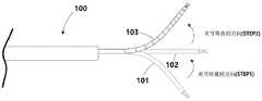
如图2至图4所示,本发明一实施例的手术器械的不对称滚动关节装置包括由关节连杆形成的多柔韧关节部102。多柔韧关节部102连接有多个关节连杆,通过驱动线操作,可具有多向自由度地做手术。As shown in FIGS. 2 to 4 , the asymmetric rolling joint device of a surgical instrument according to an embodiment of the present invention includes a multi-flexible
图2及图3表示具有多自由度的手术器械100,表示关节伸直的方向(STEP1)和关节弯曲的方向(STEP2)。此时,如图2及图3所示,本发明中说明的具有多自由度的手术器械100为用于对从STEP1到STEP2的第一方向的相对牵引力增大(意味着对称时的牵引力比起不对称时的牵引力增大)的装置,不考虑对从STEP2到STEP1的第二方向的相对牵引力增大。为了增大对从STEP2到STEP1的第二方向的相对牵引力,可相互变更图4所示的第一滚动面、第二滚动面的位置来实现。2 and 3 show the
如图4所示,多柔韧关节部101、102、103可根据第一关节连杆部110和第二关节连杆部120的滚动接触和驱动线的控制多向控制。As shown in FIG. 4 , the multi-flexible
如图4(b)所示,对于第一关节连杆部110而言,第一驱动线21和第二驱动线22分别贯通的线贯通孔111、112分别形成于关节连杆部的两侧。如图4(b)所示,对于第二关节连杆部120而言,第一驱动线21和第二驱动线22分别贯通的线贯通孔121、122分别形成于关节连杆部的两侧。因此,第一驱动线21、第二驱动线22分别贯通线贯通孔111、112、121、122而配置,可借助驱动线的牵引力多向控制多柔韧关节部101、102、103。上述的图4(b)所示的第一关节连杆部110、第二关节连杆部120表示多柔韧关节部101、102、103的一部分关节连杆,还包括关节连杆部,制作图2及图3之类的多柔韧关节部101、102、103。As shown in FIG. 4( b ), for the first
第一驱动线贯通孔111、121、第二驱动线贯通孔112、122分别形成于滚动面。更详细地,形成于第一关节连杆部110的第一驱动线贯通孔111形成于第一滚动面113或切线,第二驱动线贯通孔112形成于第二滚动面114或切线。但是,将对第一驱动线贯通孔111、第二驱动线贯通孔112的多种形成位置进行后述。The first driving wire through
并且,形成于第二关节连杆部120的第一驱动线贯通孔121形成于第一滚动面123或切线,第二驱动线贯通孔122形成于第二滚动面124或切线。但是,将对第一驱动线贯通孔121、第二驱动线贯通孔122的多种形成位置进行后述。In addition, the first drive wire through
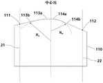
第一关节连杆部110具有与第二关节连杆部120滚动接触的第一接触滚动面。第一接触滚动面由第一滚动面113和第二滚动面114形成。作为一例,第一滚动面113具有半径Ra值,以图4(b)或图6的中心线为基准形成于左侧。第二滚动面114具有Rb值,以图4(b)的中心线为基准形成于右侧。但是,第一滚动面113、第二滚动面114可由圆形成,也可由圆和切线形成。详细说明将后述。The first
并且,第二关节连杆部120具有与第一关节连杆部110滚动接触的第二接触滚动面。第二接触滚动面由第一滚动面123和第二滚动面124形成。作为一例,第一滚动面123具有半径Ra值,以图4(b)的中心线为基准形成于左侧。第二滚动面124具有Rb值,以图4(b)的中心线为基准形成于右侧。但是,第一滚动面113、第二滚动面114可由圆形成,也可由圆和切线形成。详细说明替换为第一接触滚动面的说明。In addition, the second
并且,由于第一滚动面113、123和第二滚动面123、124的半径Ra、Rb值不同,因而滚动面不对称地形成。即,优选地,第一滚动面113、123的半径Ra值具有更大于第二滚动面123、124的半径Rb值的值。由此,具有半径Rb值的第二滚动面114、124的虚拟的圆成为与具有半径Ra值的第一滚动面113、123的虚拟的圆内切的圆。但是,即使不内切,也可根据需要实现。In addition, since the values of the radii Ra and Rb of the first rolling surfaces 113 and 123 and the second rolling surfaces 123 and 124 are different, the rolling surfaces are formed asymmetrically. That is, preferably, the value of the radius Ra of the first rolling surfaces 113 and 123 has a value larger than the value of the radius Rb of the
因此,优选地,第一关节连杆部110和第二关节连杆部120的第一接触滚动面、第二接触滚动面分别滚动接触,形成为对称对。即,优选地,由于形成为对称对,Ra和Rb值具有相同的值,如后述,第一关节连杆部的驱动线贯通孔111、112和第二关节连杆部的驱动线贯通孔121、122的形成位置也对称地形成。Therefore, preferably, the first contact rolling surface and the second contact rolling surface of the first
第一关节连杆部110的第一驱动线贯通孔111形成于第一滚动面113。第一关节连杆部110的第二驱动线贯通孔112形成于第二滚动面114。以滚动面的虚拟的水平线为基准,第一驱动线贯通孔111隔开距离D1而形成,第二驱动线贯通孔112隔开距离D2而形成。The first drive wire through
第二关节连杆部110的第一驱动线贯通孔121及第二驱动线贯通孔122以与上述相同的原理分别隔开D3(未图示)及D4(未图示)而形成。The first drive wire through-
此时,为了不对称地形成滚动面,如图4(b)所示,优选地,将形成距离D1、D3形成为短于D2、D4。此时,D1和D3或D2和D4的值相同。At this time, in order to form the rolling surface asymmetrically, as shown in FIG. 4( b ), it is preferable to form the forming distances D1 and D3 to be shorter than D2 and D4 . At this time, D1 and D3 or D2 and D4 have the same value.
如图5(a)所示,将半径Ra值从3.5增加到4.5,由此可知与牵引力的大小成正比例的力矩臂的大小(mb)增加。并且,如图5(b)所示,将半径Rb值从2.5减少到1.5,由此可知与牵引力的大小成正比例的力矩臂的大小(mb)增加。As shown in Fig. 5(a), when the value of the radius Ra is increased from 3.5 to 4.5, it can be seen that the magnitude (mb) of the moment arm proportional to the magnitude of the traction force increases. Furthermore, as shown in FIG. 5( b ), the value of the radius Rb is decreased from 2.5 to 1.5, and it can be seen that the magnitude (mb) of the moment arm proportional to the magnitude of the traction force increases.
以下,例举多种实施例说明滚动面和线贯通孔的形成位置。但是,仅说明第一关节连杆的滚动面和线贯通孔,第二关节连杆的滚动面和线贯通孔替换为上述例。Hereinafter, various examples are given to describe the formation positions of the rolling surface and the wire through-holes. However, only the rolling surface and the wire through hole of the first joint link will be described, and the rolling surface and the wire through hole of the second joint link will be replaced with the above example.
说明第一滚动面113、第二滚动面114和第一驱动线贯通孔111、第二驱动线贯通孔112的第一实施例。A first embodiment of the first rolling
如图6所示,第一滚动面113和第二滚动面114分别为由半径Ra和Rb形成的圆的一部分。此时,第一滚动面的半径Ra1和第二滚动面的半径具有不同的值。即,第一滚动面的半径Ra具有相比于第二滚动面的半径Rb相对更大的值,上述滚动面不对称地形成。并且,以第二滚动面的半径Rb为基准形成的圆为与以第一滚动面的半径Ra为基准形成的圆内切的圆。As shown in FIG. 6 , the first rolling
并且,第一驱动线贯通孔111、第二驱动线贯通孔112分别形成于第一滚动面113、第二滚动面114,第一驱动线贯通孔111的形成高度具有相比于第二驱动线贯通孔112的形成高度相对小的值,滚动面不对称地形成。有关形成高度的距离D1、D2的测定可参照图4(b)。In addition, the first driving wire through-
说明第一滚动面113、第二滚动面114和第一驱动线贯通孔111、第二驱动线贯通孔112的第二实施例。A second embodiment of the first rolling
如图7所示,第一滚动面113a、113b由以第一半径Ra形成的一部分圆113a和与以第一半径形成的一部分圆113a相接的第一切线113b形成。第二滚动面114a、114b由以第二半径Rb形成的一部分圆114a和与以第二半径形成的一部分圆相接的第二切线114b形成。并且,第一半径Ra和第二半径Rb具有不同的值,接触滚动面不对称地形成。第一半径Ra具有相比于第二半径Rb相对更大的值,第二切线114b的斜率具有相比于第一切线113b的斜率相对更大的值,滚动面不对称地形成。As shown in FIG. 7 , the
并且,第一驱动线贯通孔111、第二驱动线贯通孔112分别形成于第一切线113b、第二切线114b,第一驱动线贯通孔111的形成高度具有相比于第二驱动线贯通孔112的形成高度相对小的值,上述滚动面不对称地形成。有关形成高度的距离D1、D2的测定可参照图4(b)。In addition, the first drive line through-
说明第一滚动面113、第二滚动面114和第一驱动线贯通孔111、第二驱动线贯通孔112的第三实施例。A third embodiment of the first rolling
如图8所示,第一滚动面113a、113b由以第一半径Ra形成的一部分圆113a和与以第一半径形成的一部分圆相接的切线113b形成。第二滚动面114由以第二半径Rb形成的一部分圆114形成。第一半径Ra和第二半径Rb具有不同的值,接触滚动面不对称地形成。As shown in FIG. 8 , the
另一方面,第一驱动线贯通孔111形成于与由第一半径Ra形成的一部分圆相接的切线113b,第二驱动线贯通孔112形成于由第二半径Rb形成的一部分圆114。第一驱动线贯通孔111的形成高度具有相比于第二驱动线贯通孔112的形成高度相对小的值,滚动面不对称地形成。有关形成高度的距离D1、D2的测定可参照图4(b)。On the other hand, the first drive line through-
说明第一滚动面113、第二滚动面114和第一驱动线贯通孔111、第二驱动线贯通孔112的第四实施例。A fourth embodiment of the first rolling
如图9所示,第一滚动面113由以第一半径Ra形成的一部分圆形成,第二滚动面114a、114b由以第二半径Rb形成的一部分圆114a和与以第一半径形成的一部分圆相接的切线114b形成。第一半径Ra和第二半径Rb具有不同的值,接触滚动面不对称地形成。As shown in FIG. 9 , the first rolling
另一方面,第一驱动线贯通孔111形成于由第一半径Ra形成的一部分圆113,第二驱动线贯通孔112形成于与由第二半径形成的一部分圆相接的切线114b。第一驱动线贯通孔111的形成高度具有相比于第二驱动线贯通孔的形成高度相对大的值,滚动面不对称地形成。有关形成高度的距离D1、D2的测定可参照图4(b)。On the other hand, the first drive line through-
在第二实施例、第三实施例、第四实施例中,以第二半径Rb为基准形成的圆为与以第一半径Ra为基准形成的圆内切的圆。并且,在第三实施例、第四实施例中,第一半径Ra具有相比于第二半径Rb相对更大的值,上述滚动面不对称地形成。In the second embodiment, the third embodiment, and the fourth embodiment, the circle formed on the basis of the second radius Rb is a circle inscribed with the circle formed on the basis of the first radius Ra. Furthermore, in the third and fourth embodiments, the first radius Ra has a relatively larger value than the second radius Rb, and the rolling surfaces are formed asymmetrically.
在说明本发明的过程中,现有技术及对本发明所属技术领域的普通技术人员显而易见的事项可省略说明,在不脱离本发明的技术思想的范围内可充分参照这种省略的结构要素(方法)及功能的说明。并且,上述的本发明的结构要素仅用来便于说明本发明,在不脱离本发明的技术思想的范围内可追加在此未说明的结构要素。During the description of the present invention, the description of the prior art and matters obvious to those skilled in the art to which the present invention pertains may be omitted, and such omitted structural elements (methods) may be fully referred to within the scope of not departing from the technical idea of the present invention. ) and a description of the function. In addition, the above-mentioned structural elements of the present invention are only used for convenience of description of the present invention, and structural elements not described herein may be added within the scope of not departing from the technical idea of the present invention.
上述的各部的结构及功能的说明仅为了便于说明而分离,根据需要,一种结构及功能能够以其他结构要素组合而实现,或者也可以更细分化而实现。The above-described structures and functions of the respective components are described separately for convenience of description, and one structure and function can be realized by combining other components, or more subdivided, as needed.
以上,参照本发明的一实施例说明,但本发明不局限于此,可多样地变形及应用。即,在不脱离本发明的要旨的范围内可进行多种变形,这是本发明所属技术领域的普通技术人员可容易理解的。并且,需要注意的是,当判断本发明相关公知功能及其结构或对本发明的各个结构的结合关系的具体说明有可能不必要地混淆本发明的要旨时,省略其具体说明。As mentioned above, although an Example of this invention was demonstrated, this invention is not limited to this, Various deformation|transformation and application are possible. That is, various modifications can be made without departing from the gist of the present invention, which can be easily understood by those skilled in the art to which the present invention pertains. Also, it should be noted that when it is judged that the specific description of the related known functions and structures of the present invention or the combination relationship of the various structures of the present invention may unnecessarily obscure the gist of the present invention, the specific description thereof is omitted.
Claims (16)
Applications Claiming Priority (2)
| Application Number | Priority Date | Filing Date | Title |
|---|---|---|---|
| KR10-2021-0044885 | 2021-04-06 | ||
| KR1020210044885AKR102559600B1 (en) | 2021-04-06 | 2021-04-06 | Asymmetric rolling contact joint of sugical instrument |
Publications (1)
| Publication Number | Publication Date |
|---|---|
| CN115153675Atrue CN115153675A (en) | 2022-10-11 |
Family
ID=77398413
Family Applications (1)
| Application Number | Title | Priority Date | Filing Date |
|---|---|---|---|
| CN202110954625.1APendingCN115153675A (en) | 2021-04-06 | 2021-08-19 | Asymmetric rolling joint device for surgical instruments |
Country Status (4)
| Country | Link |
|---|---|
| US (1) | US20220313231A1 (en) |
| EP (1) | EP4070736A1 (en) |
| KR (1) | KR102559600B1 (en) |
| CN (1) | CN115153675A (en) |
Citations (5)
| Publication number | Priority date | Publication date | Assignee | Title |
|---|---|---|---|---|
| US20080249364A1 (en)* | 2007-04-04 | 2008-10-09 | Richard Wolf Gmbh | Endoscopic instrument |
| WO2013039999A2 (en)* | 2011-09-13 | 2013-03-21 | Medrobotics Corporation | Highly articulated probes with anti-twist link arrangement, methods of formation thereof, and methods of performing medical procedures |
| KR20130132233A (en)* | 2012-05-25 | 2013-12-04 | 삼성전자주식회사 | Arm unit and robot having the same |
| US20160302812A1 (en)* | 2015-04-16 | 2016-10-20 | Ethicon Endo-Surgery, Llc | Ultrasonic surgical instrument with rigidizing articulation drive members |
| US20180250053A1 (en)* | 2015-10-27 | 2018-09-06 | Scott & White Healthcare | Line Passing Devices and Related Kits and Methods |
Family Cites Families (12)
| Publication number | Priority date | Publication date | Assignee | Title |
|---|---|---|---|---|
| DE19534112A1 (en)* | 1995-09-14 | 1997-03-20 | Wolf Gmbh Richard | Endoscopic instrument with steerable distal end |
| EP1470790B1 (en)* | 2003-04-24 | 2006-04-05 | Zimmer GmbH | Instrumentsystem for pedicle screw |
| US8920369B2 (en)* | 2009-06-24 | 2014-12-30 | Shifamed Holdings, Llc | Steerable delivery sheaths |
| US8578810B2 (en)* | 2011-02-14 | 2013-11-12 | Intuitive Surgical Operations, Inc. | Jointed link structures exhibiting preferential bending, and related methods |
| KR101405087B1 (en)* | 2012-04-27 | 2014-06-10 | 한양대학교 에리카산학협력단 | An articulation for surgical instrument |
| WO2015079809A1 (en)* | 2013-11-29 | 2015-06-04 | オリンパス株式会社 | Curve part of endoscope |
| WO2016123139A2 (en)* | 2015-01-26 | 2016-08-04 | Intuitive Surgical Operations, Inc. | Rolling-contact joint mechanisms and methods |
| US11457987B2 (en)* | 2015-05-15 | 2022-10-04 | The Johns Hopkins University | Manipulator device and therapeutic and diagnostic methods |
| CN118121305A (en)* | 2019-08-15 | 2024-06-04 | 上海微创医疗机器人(集团)股份有限公司 | Surgical robot and surgical instrument |
| KR102321453B1 (en)* | 2019-10-23 | 2021-11-04 | 한국과학기술연구원 | Articulating structure with enhanced bending force, and Tube insert device haivng the same |
| CN111000636B (en)* | 2019-12-30 | 2021-08-27 | 上海微创医疗机器人(集团)股份有限公司 | Transmission assembly, drive box, surgical instrument system and robot system |
| US20230380918A1 (en)* | 2020-09-30 | 2023-11-30 | Shenzhen Jingfeng Medical Technology Co., Ltd. | Surgical instrument, slave operating equipment, and surgical robot |
- 2021
- 2021-04-06KRKR1020210044885Apatent/KR102559600B1/enactiveActive
- 2021-08-18EPEP21191815.6Apatent/EP4070736A1/enactivePending
- 2021-08-19USUS17/406,834patent/US20220313231A1/enactivePending
- 2021-08-19CNCN202110954625.1Apatent/CN115153675A/enactivePending
Patent Citations (5)
| Publication number | Priority date | Publication date | Assignee | Title |
|---|---|---|---|---|
| US20080249364A1 (en)* | 2007-04-04 | 2008-10-09 | Richard Wolf Gmbh | Endoscopic instrument |
| WO2013039999A2 (en)* | 2011-09-13 | 2013-03-21 | Medrobotics Corporation | Highly articulated probes with anti-twist link arrangement, methods of formation thereof, and methods of performing medical procedures |
| KR20130132233A (en)* | 2012-05-25 | 2013-12-04 | 삼성전자주식회사 | Arm unit and robot having the same |
| US20160302812A1 (en)* | 2015-04-16 | 2016-10-20 | Ethicon Endo-Surgery, Llc | Ultrasonic surgical instrument with rigidizing articulation drive members |
| US20180250053A1 (en)* | 2015-10-27 | 2018-09-06 | Scott & White Healthcare | Line Passing Devices and Related Kits and Methods |
Also Published As
| Publication number | Publication date |
|---|---|
| KR102559600B1 (en) | 2023-07-25 |
| EP4070736A1 (en) | 2022-10-12 |
| US20220313231A1 (en) | 2022-10-06 |
| KR20220138766A (en) | 2022-10-13 |
Similar Documents
| Publication | Publication Date | Title |
|---|---|---|
| US4432349A (en) | Articulated tube structure for use in an endoscope | |
| CN106963494B (en) | Operating robot snakelike joint, surgical instrument and endoscope | |
| CN112770878A (en) | Flexible driving device | |
| CN100376200C (en) | Endoscope angle portion | |
| KR20140037032A (en) | Jointed link structures exhibiting preferential bending, and related methods | |
| CN112822971A (en) | Joint | |
| CN209750985U (en) | Endoscope with a detachable handle | |
| CN114333607B (en) | Display device | |
| KR102434463B1 (en) | Cable actuation mechanism for steerable endoscope | |
| CN110584571B (en) | Double-helix snake bone and endoscope | |
| CN115153675A (en) | Asymmetric rolling joint device for surgical instruments | |
| CN115429201A (en) | Omnidirectional bendable endoscope snake component and endoscope | |
| CN110744548A (en) | A unified decoupling method for driving line coupling relationship of multi-line-driven continuum manipulators | |
| CN113456231B (en) | A notch-type continuum robot based on a cross-bending beam structure | |
| JP2017515076A (en) | Rocker joint for link plate chain | |
| CN109645937A (en) | Curvature section of endoscope and endoscope | |
| CN107532683B (en) | Drive belt arrangement and components for constructing the drive belt arrangement | |
| CN204797778U (en) | Unit festival, snake bone pipe and endoscope | |
| CN109895073B (en) | Continuous body robot driven by leaf springs | |
| CN112971989A (en) | Flexible joint structure | |
| Ryu et al. | Analysis and simulation of large deflection of a multi-segmented catheter tube under wire tension | |
| CN115316914A (en) | Bendable structures, flexible instruments and endoscopes | |
| CN215079600U (en) | Flexible joint structure | |
| CN219331588U (en) | Snake bone and surgical instrument | |
| CN112205950A (en) | A bone joint piece and concatenation formula snake bone for concatenation formula snake bone |
Legal Events
| Date | Code | Title | Description |
|---|---|---|---|
| PB01 | Publication | ||
| PB01 | Publication | ||
| SE01 | Entry into force of request for substantive examination | ||
| SE01 | Entry into force of request for substantive examination | ||
| CB02 | Change of applicant information | ||
| CB02 | Change of applicant information | Address after:193 Quest 193, Wenji Road, Ryucheng District, Daejeon, South Korea Applicant after:Ron Surgery, Inc. Applicant after:KOREA ADVANCED INSTITUTE OF SCIENCE AND TECHNOLOGY Address before:193 Quest 193, Wenji Road, Ryucheng District, Daejeon, South Korea Applicant before:Yijin Jungu powder Co.,Ltd. Applicant before:KOREA ADVANCED INSTITUTE OF SCIENCE AND TECHNOLOGY |