CN115151210A - Surgical system for giving and confirming removal of parts of organs - Google Patents
Surgical system for giving and confirming removal of parts of organsDownload PDFInfo
- Publication number
- CN115151210A CN115151210ACN202080091332.9ACN202080091332ACN115151210ACN 115151210 ACN115151210 ACN 115151210ACN 202080091332 ACN202080091332 ACN 202080091332ACN 115151210 ACN115151210 ACN 115151210A
- Authority
- CN
- China
- Prior art keywords
- surgical
- visualization
- tissue
- data
- organ
- Prior art date
- Legal status (The legal status is an assumption and is not a legal conclusion. Google has not performed a legal analysis and makes no representation as to the accuracy of the status listed.)
- Pending
Links
Images


Classifications
- A—HUMAN NECESSITIES
- A61—MEDICAL OR VETERINARY SCIENCE; HYGIENE
- A61B—DIAGNOSIS; SURGERY; IDENTIFICATION
- A61B90/00—Instruments, implements or accessories specially adapted for surgery or diagnosis and not covered by any of the groups A61B1/00 - A61B50/00, e.g. for luxation treatment or for protecting wound edges
- A61B90/36—Image-producing devices or illumination devices not otherwise provided for
- A61B90/361—Image-producing devices, e.g. surgical cameras
- A—HUMAN NECESSITIES
- A61—MEDICAL OR VETERINARY SCIENCE; HYGIENE
- A61B—DIAGNOSIS; SURGERY; IDENTIFICATION
- A61B1/00—Instruments for performing medical examinations of the interior of cavities or tubes of the body by visual or photographical inspection, e.g. endoscopes; Illuminating arrangements therefor
- A61B1/00002—Operational features of endoscopes
- A61B1/00004—Operational features of endoscopes characterised by electronic signal processing
- A61B1/00009—Operational features of endoscopes characterised by electronic signal processing of image signals during a use of endoscope
- A61B1/000094—Operational features of endoscopes characterised by electronic signal processing of image signals during a use of endoscope extracting biological structures
- A—HUMAN NECESSITIES
- A61—MEDICAL OR VETERINARY SCIENCE; HYGIENE
- A61B—DIAGNOSIS; SURGERY; IDENTIFICATION
- A61B1/00—Instruments for performing medical examinations of the interior of cavities or tubes of the body by visual or photographical inspection, e.g. endoscopes; Illuminating arrangements therefor
- A61B1/00064—Constructional details of the endoscope body
- A61B1/00071—Insertion part of the endoscope body
- A61B1/0008—Insertion part of the endoscope body characterised by distal tip features
- A61B1/00097—Sensors
- A—HUMAN NECESSITIES
- A61—MEDICAL OR VETERINARY SCIENCE; HYGIENE
- A61B—DIAGNOSIS; SURGERY; IDENTIFICATION
- A61B1/00—Instruments for performing medical examinations of the interior of cavities or tubes of the body by visual or photographical inspection, e.g. endoscopes; Illuminating arrangements therefor
- A61B1/00147—Holding or positioning arrangements
- A61B1/00149—Holding or positioning arrangements using articulated arms
- A—HUMAN NECESSITIES
- A61—MEDICAL OR VETERINARY SCIENCE; HYGIENE
- A61B—DIAGNOSIS; SURGERY; IDENTIFICATION
- A61B1/00—Instruments for performing medical examinations of the interior of cavities or tubes of the body by visual or photographical inspection, e.g. endoscopes; Illuminating arrangements therefor
- A61B1/00163—Optical arrangements
- A61B1/00193—Optical arrangements adapted for stereoscopic vision
- A—HUMAN NECESSITIES
- A61—MEDICAL OR VETERINARY SCIENCE; HYGIENE
- A61B—DIAGNOSIS; SURGERY; IDENTIFICATION
- A61B1/00—Instruments for performing medical examinations of the interior of cavities or tubes of the body by visual or photographical inspection, e.g. endoscopes; Illuminating arrangements therefor
- A61B1/00163—Optical arrangements
- A61B1/00194—Optical arrangements adapted for three-dimensional imaging
- A—HUMAN NECESSITIES
- A61—MEDICAL OR VETERINARY SCIENCE; HYGIENE
- A61B—DIAGNOSIS; SURGERY; IDENTIFICATION
- A61B1/00—Instruments for performing medical examinations of the interior of cavities or tubes of the body by visual or photographical inspection, e.g. endoscopes; Illuminating arrangements therefor
- A61B1/04—Instruments for performing medical examinations of the interior of cavities or tubes of the body by visual or photographical inspection, e.g. endoscopes; Illuminating arrangements therefor combined with photographic or television appliances
- A61B1/05—Instruments for performing medical examinations of the interior of cavities or tubes of the body by visual or photographical inspection, e.g. endoscopes; Illuminating arrangements therefor combined with photographic or television appliances characterised by the image sensor, e.g. camera, being in the distal end portion
- A—HUMAN NECESSITIES
- A61—MEDICAL OR VETERINARY SCIENCE; HYGIENE
- A61B—DIAGNOSIS; SURGERY; IDENTIFICATION
- A61B1/00—Instruments for performing medical examinations of the interior of cavities or tubes of the body by visual or photographical inspection, e.g. endoscopes; Illuminating arrangements therefor
- A61B1/06—Instruments for performing medical examinations of the interior of cavities or tubes of the body by visual or photographical inspection, e.g. endoscopes; Illuminating arrangements therefor with illuminating arrangements
- A61B1/0605—Instruments for performing medical examinations of the interior of cavities or tubes of the body by visual or photographical inspection, e.g. endoscopes; Illuminating arrangements therefor with illuminating arrangements for spatially modulated illumination
- A—HUMAN NECESSITIES
- A61—MEDICAL OR VETERINARY SCIENCE; HYGIENE
- A61B—DIAGNOSIS; SURGERY; IDENTIFICATION
- A61B1/00—Instruments for performing medical examinations of the interior of cavities or tubes of the body by visual or photographical inspection, e.g. endoscopes; Illuminating arrangements therefor
- A61B1/06—Instruments for performing medical examinations of the interior of cavities or tubes of the body by visual or photographical inspection, e.g. endoscopes; Illuminating arrangements therefor with illuminating arrangements
- A61B1/0638—Instruments for performing medical examinations of the interior of cavities or tubes of the body by visual or photographical inspection, e.g. endoscopes; Illuminating arrangements therefor with illuminating arrangements providing two or more wavelengths
- A—HUMAN NECESSITIES
- A61—MEDICAL OR VETERINARY SCIENCE; HYGIENE
- A61B—DIAGNOSIS; SURGERY; IDENTIFICATION
- A61B17/00—Surgical instruments, devices or methods
- A61B17/32—Surgical cutting instruments
- A61B17/3205—Excision instruments
- A—HUMAN NECESSITIES
- A61—MEDICAL OR VETERINARY SCIENCE; HYGIENE
- A61B—DIAGNOSIS; SURGERY; IDENTIFICATION
- A61B34/00—Computer-aided surgery; Manipulators or robots specially adapted for use in surgery
- A61B34/10—Computer-aided planning, simulation or modelling of surgical operations
- A—HUMAN NECESSITIES
- A61—MEDICAL OR VETERINARY SCIENCE; HYGIENE
- A61B—DIAGNOSIS; SURGERY; IDENTIFICATION
- A61B90/00—Instruments, implements or accessories specially adapted for surgery or diagnosis and not covered by any of the groups A61B1/00 - A61B50/00, e.g. for luxation treatment or for protecting wound edges
- A61B90/36—Image-producing devices or illumination devices not otherwise provided for
- A61B90/37—Surgical systems with images on a monitor during operation
- G—PHYSICS
- G01—MEASURING; TESTING
- G01B—MEASURING LENGTH, THICKNESS OR SIMILAR LINEAR DIMENSIONS; MEASURING ANGLES; MEASURING AREAS; MEASURING IRREGULARITIES OF SURFACES OR CONTOURS
- G01B11/00—Measuring arrangements characterised by the use of optical techniques
- G01B11/02—Measuring arrangements characterised by the use of optical techniques for measuring length, width or thickness
- G01B11/026—Measuring arrangements characterised by the use of optical techniques for measuring length, width or thickness by measuring distance between sensor and object
- G—PHYSICS
- G01—MEASURING; TESTING
- G01B—MEASURING LENGTH, THICKNESS OR SIMILAR LINEAR DIMENSIONS; MEASURING ANGLES; MEASURING AREAS; MEASURING IRREGULARITIES OF SURFACES OR CONTOURS
- G01B11/00—Measuring arrangements characterised by the use of optical techniques
- G01B11/24—Measuring arrangements characterised by the use of optical techniques for measuring contours or curvatures
- G01B11/25—Measuring arrangements characterised by the use of optical techniques for measuring contours or curvatures by projecting a pattern, e.g. one or more lines, moiré fringes on the object
- G—PHYSICS
- G16—INFORMATION AND COMMUNICATION TECHNOLOGY [ICT] SPECIALLY ADAPTED FOR SPECIFIC APPLICATION FIELDS
- G16H—HEALTHCARE INFORMATICS, i.e. INFORMATION AND COMMUNICATION TECHNOLOGY [ICT] SPECIALLY ADAPTED FOR THE HANDLING OR PROCESSING OF MEDICAL OR HEALTHCARE DATA
- G16H20/00—ICT specially adapted for therapies or health-improving plans, e.g. for handling prescriptions, for steering therapy or for monitoring patient compliance
- G16H20/40—ICT specially adapted for therapies or health-improving plans, e.g. for handling prescriptions, for steering therapy or for monitoring patient compliance relating to mechanical, radiation or invasive therapies, e.g. surgery, laser therapy, dialysis or acupuncture
- G—PHYSICS
- G16—INFORMATION AND COMMUNICATION TECHNOLOGY [ICT] SPECIALLY ADAPTED FOR SPECIFIC APPLICATION FIELDS
- G16H—HEALTHCARE INFORMATICS, i.e. INFORMATION AND COMMUNICATION TECHNOLOGY [ICT] SPECIALLY ADAPTED FOR THE HANDLING OR PROCESSING OF MEDICAL OR HEALTHCARE DATA
- G16H40/00—ICT specially adapted for the management or administration of healthcare resources or facilities; ICT specially adapted for the management or operation of medical equipment or devices
- G16H40/60—ICT specially adapted for the management or administration of healthcare resources or facilities; ICT specially adapted for the management or operation of medical equipment or devices for the operation of medical equipment or devices
- G16H40/63—ICT specially adapted for the management or administration of healthcare resources or facilities; ICT specially adapted for the management or operation of medical equipment or devices for the operation of medical equipment or devices for local operation
- G—PHYSICS
- G16—INFORMATION AND COMMUNICATION TECHNOLOGY [ICT] SPECIALLY ADAPTED FOR SPECIFIC APPLICATION FIELDS
- G16H—HEALTHCARE INFORMATICS, i.e. INFORMATION AND COMMUNICATION TECHNOLOGY [ICT] SPECIALLY ADAPTED FOR THE HANDLING OR PROCESSING OF MEDICAL OR HEALTHCARE DATA
- G16H50/00—ICT specially adapted for medical diagnosis, medical simulation or medical data mining; ICT specially adapted for detecting, monitoring or modelling epidemics or pandemics
- G16H50/20—ICT specially adapted for medical diagnosis, medical simulation or medical data mining; ICT specially adapted for detecting, monitoring or modelling epidemics or pandemics for computer-aided diagnosis, e.g. based on medical expert systems
- G—PHYSICS
- G16—INFORMATION AND COMMUNICATION TECHNOLOGY [ICT] SPECIALLY ADAPTED FOR SPECIFIC APPLICATION FIELDS
- G16H—HEALTHCARE INFORMATICS, i.e. INFORMATION AND COMMUNICATION TECHNOLOGY [ICT] SPECIALLY ADAPTED FOR THE HANDLING OR PROCESSING OF MEDICAL OR HEALTHCARE DATA
- G16H50/00—ICT specially adapted for medical diagnosis, medical simulation or medical data mining; ICT specially adapted for detecting, monitoring or modelling epidemics or pandemics
- G16H50/50—ICT specially adapted for medical diagnosis, medical simulation or medical data mining; ICT specially adapted for detecting, monitoring or modelling epidemics or pandemics for simulation or modelling of medical disorders
- A—HUMAN NECESSITIES
- A61—MEDICAL OR VETERINARY SCIENCE; HYGIENE
- A61B—DIAGNOSIS; SURGERY; IDENTIFICATION
- A61B17/00—Surgical instruments, devices or methods
- A61B2017/00017—Electrical control of surgical instruments
- A61B2017/00199—Electrical control of surgical instruments with a console, e.g. a control panel with a display
- A—HUMAN NECESSITIES
- A61—MEDICAL OR VETERINARY SCIENCE; HYGIENE
- A61B—DIAGNOSIS; SURGERY; IDENTIFICATION
- A61B17/00—Surgical instruments, devices or methods
- A61B2017/00743—Type of operation; Specification of treatment sites
- A61B2017/00809—Lung operations
- A—HUMAN NECESSITIES
- A61—MEDICAL OR VETERINARY SCIENCE; HYGIENE
- A61B—DIAGNOSIS; SURGERY; IDENTIFICATION
- A61B34/00—Computer-aided surgery; Manipulators or robots specially adapted for use in surgery
- A61B34/10—Computer-aided planning, simulation or modelling of surgical operations
- A61B2034/101—Computer-aided simulation of surgical operations
- A61B2034/105—Modelling of the patient, e.g. for ligaments or bones
- A—HUMAN NECESSITIES
- A61—MEDICAL OR VETERINARY SCIENCE; HYGIENE
- A61B—DIAGNOSIS; SURGERY; IDENTIFICATION
- A61B34/00—Computer-aided surgery; Manipulators or robots specially adapted for use in surgery
- A61B34/10—Computer-aided planning, simulation or modelling of surgical operations
- A61B2034/107—Visualisation of planned trajectories or target regions
- A—HUMAN NECESSITIES
- A61—MEDICAL OR VETERINARY SCIENCE; HYGIENE
- A61B—DIAGNOSIS; SURGERY; IDENTIFICATION
- A61B34/00—Computer-aided surgery; Manipulators or robots specially adapted for use in surgery
- A61B34/20—Surgical navigation systems; Devices for tracking or guiding surgical instruments, e.g. for frameless stereotaxis
- A61B2034/2046—Tracking techniques
- A61B2034/2065—Tracking using image or pattern recognition
- A—HUMAN NECESSITIES
- A61—MEDICAL OR VETERINARY SCIENCE; HYGIENE
- A61B—DIAGNOSIS; SURGERY; IDENTIFICATION
- A61B34/00—Computer-aided surgery; Manipulators or robots specially adapted for use in surgery
- A61B34/25—User interfaces for surgical systems
- A61B2034/252—User interfaces for surgical systems indicating steps of a surgical procedure
- A—HUMAN NECESSITIES
- A61—MEDICAL OR VETERINARY SCIENCE; HYGIENE
- A61B—DIAGNOSIS; SURGERY; IDENTIFICATION
- A61B90/00—Instruments, implements or accessories specially adapted for surgery or diagnosis and not covered by any of the groups A61B1/00 - A61B50/00, e.g. for luxation treatment or for protecting wound edges
- A61B90/30—Devices for illuminating a surgical field, the devices having an interrelation with other surgical devices or with a surgical procedure
- A61B2090/304—Devices for illuminating a surgical field, the devices having an interrelation with other surgical devices or with a surgical procedure using chemi-luminescent materials
- A—HUMAN NECESSITIES
- A61—MEDICAL OR VETERINARY SCIENCE; HYGIENE
- A61B—DIAGNOSIS; SURGERY; IDENTIFICATION
- A61B90/00—Instruments, implements or accessories specially adapted for surgery or diagnosis and not covered by any of the groups A61B1/00 - A61B50/00, e.g. for luxation treatment or for protecting wound edges
- A61B90/36—Image-producing devices or illumination devices not otherwise provided for
- A61B2090/364—Correlation of different images or relation of image positions in respect to the body
- A—HUMAN NECESSITIES
- A61—MEDICAL OR VETERINARY SCIENCE; HYGIENE
- A61B—DIAGNOSIS; SURGERY; IDENTIFICATION
- A61B90/00—Instruments, implements or accessories specially adapted for surgery or diagnosis and not covered by any of the groups A61B1/00 - A61B50/00, e.g. for luxation treatment or for protecting wound edges
- A61B90/36—Image-producing devices or illumination devices not otherwise provided for
- A61B90/37—Surgical systems with images on a monitor during operation
- A61B2090/371—Surgical systems with images on a monitor during operation with simultaneous use of two cameras
- A—HUMAN NECESSITIES
- A61—MEDICAL OR VETERINARY SCIENCE; HYGIENE
- A61B—DIAGNOSIS; SURGERY; IDENTIFICATION
- A61B90/00—Instruments, implements or accessories specially adapted for surgery or diagnosis and not covered by any of the groups A61B1/00 - A61B50/00, e.g. for luxation treatment or for protecting wound edges
- A61B90/36—Image-producing devices or illumination devices not otherwise provided for
- A61B90/37—Surgical systems with images on a monitor during operation
- A61B2090/373—Surgical systems with images on a monitor during operation using light, e.g. by using optical scanners
- A—HUMAN NECESSITIES
- A61—MEDICAL OR VETERINARY SCIENCE; HYGIENE
- A61B—DIAGNOSIS; SURGERY; IDENTIFICATION
- A61B5/00—Measuring for diagnostic purposes; Identification of persons
- A61B5/08—Measuring devices for evaluating the respiratory organs
- A61B5/091—Measuring volume of inspired or expired gases, e.g. to determine lung capacity
- A—HUMAN NECESSITIES
- A61—MEDICAL OR VETERINARY SCIENCE; HYGIENE
- A61M—DEVICES FOR INTRODUCING MEDIA INTO, OR ONTO, THE BODY; DEVICES FOR TRANSDUCING BODY MEDIA OR FOR TAKING MEDIA FROM THE BODY; DEVICES FOR PRODUCING OR ENDING SLEEP OR STUPOR
- A61M16/00—Devices for influencing the respiratory system of patients by gas treatment, e.g. ventilators; Tracheal tubes
- A61M16/0003—Accessories therefor, e.g. sensors, vibrators, negative pressure
- A—HUMAN NECESSITIES
- A61—MEDICAL OR VETERINARY SCIENCE; HYGIENE
- A61M—DEVICES FOR INTRODUCING MEDIA INTO, OR ONTO, THE BODY; DEVICES FOR TRANSDUCING BODY MEDIA OR FOR TAKING MEDIA FROM THE BODY; DEVICES FOR PRODUCING OR ENDING SLEEP OR STUPOR
- A61M2230/00—Measuring parameters of the user
- A61M2230/40—Respiratory characteristics
- A61M2230/43—Composition of exhalation
- A61M2230/432—Composition of exhalation partial CO2 pressure (P-CO2)
- G—PHYSICS
- G01—MEASURING; TESTING
- G01J—MEASUREMENT OF INTENSITY, VELOCITY, SPECTRAL CONTENT, POLARISATION, PHASE OR PULSE CHARACTERISTICS OF INFRARED, VISIBLE OR ULTRAVIOLET LIGHT; COLORIMETRY; RADIATION PYROMETRY
- G01J3/00—Spectrometry; Spectrophotometry; Monochromators; Measuring colours
- G01J3/28—Investigating the spectrum
- G01J3/2823—Imaging spectrometer
- G01J2003/2826—Multispectral imaging, e.g. filter imaging
- G—PHYSICS
- G01—MEASURING; TESTING
- G01S—RADIO DIRECTION-FINDING; RADIO NAVIGATION; DETERMINING DISTANCE OR VELOCITY BY USE OF RADIO WAVES; LOCATING OR PRESENCE-DETECTING BY USE OF THE REFLECTION OR RERADIATION OF RADIO WAVES; ANALOGOUS ARRANGEMENTS USING OTHER WAVES
- G01S17/00—Systems using the reflection or reradiation of electromagnetic waves other than radio waves, e.g. lidar systems
- G01S17/02—Systems using the reflection of electromagnetic waves other than radio waves
- G01S17/06—Systems determining position data of a target
- G01S17/08—Systems determining position data of a target for measuring distance only
- G—PHYSICS
- G01—MEASURING; TESTING
- G01S—RADIO DIRECTION-FINDING; RADIO NAVIGATION; DETERMINING DISTANCE OR VELOCITY BY USE OF RADIO WAVES; LOCATING OR PRESENCE-DETECTING BY USE OF THE REFLECTION OR RERADIATION OF RADIO WAVES; ANALOGOUS ARRANGEMENTS USING OTHER WAVES
- G01S17/00—Systems using the reflection or reradiation of electromagnetic waves other than radio waves, e.g. lidar systems
- G01S17/88—Lidar systems specially adapted for specific applications
- G01S17/89—Lidar systems specially adapted for specific applications for mapping or imaging
- G01S17/894—3D imaging with simultaneous measurement of time-of-flight at a 2D array of receiver pixels, e.g. time-of-flight cameras or flash lidar
Landscapes
- Health & Medical Sciences (AREA)
- Life Sciences & Earth Sciences (AREA)
- Surgery (AREA)
- Engineering & Computer Science (AREA)
- Public Health (AREA)
- Medical Informatics (AREA)
- Biomedical Technology (AREA)
- General Health & Medical Sciences (AREA)
- Nuclear Medicine, Radiotherapy & Molecular Imaging (AREA)
- Heart & Thoracic Surgery (AREA)
- Molecular Biology (AREA)
- Animal Behavior & Ethology (AREA)
- Veterinary Medicine (AREA)
- Pathology (AREA)
- Physics & Mathematics (AREA)
- Radiology & Medical Imaging (AREA)
- Biophysics (AREA)
- Optics & Photonics (AREA)
- Epidemiology (AREA)
- Primary Health Care (AREA)
- Oral & Maxillofacial Surgery (AREA)
- Robotics (AREA)
- Signal Processing (AREA)
- General Physics & Mathematics (AREA)
- Data Mining & Analysis (AREA)
- Databases & Information Systems (AREA)
- Gynecology & Obstetrics (AREA)
- Business, Economics & Management (AREA)
- Computer Vision & Pattern Recognition (AREA)
- Urology & Nephrology (AREA)
- General Business, Economics & Management (AREA)
- Endoscopes (AREA)
- Surgical Instruments (AREA)
Abstract
Description
Translated fromChinese背景技术Background technique
外科系统通常结合有成像系统,该成像系统可允许临床医生例如在一个或多个显示器(诸如监视器)上观看外科部位和/或其一个或多个部分。显示器可以是手术室本地的和/或远程的。成像系统可包括具有相机的观察镜,该观察镜观看外科部位并将视图传输到临床医生可观看的显示器。观察镜包括但不限于关节镜、血管镜、支气管镜、胆道镜、结肠镜、膀胱镜、十二指肠镜、肠镜、食管胃-十二指肠镜(胃镜)、内窥镜、喉镜、鼻咽-肾镜、乙状结肠镜、胸腔镜、输尿管镜和外镜。成像系统可受到它们能够识别和/或传达给临床医生的信息的限制。例如,某些成像系统可能无法在术中识别三维空间内的某些隐蔽结构、物理轮廓和/或尺寸。另外,某些成像系统可能无法在术中将某些信息传送和/或传达给临床医生。Surgical systems typically incorporate an imaging system that may allow a clinician to view the surgical site and/or one or more portions thereof, eg, on one or more displays, such as monitors. Displays can be local and/or remote to the operating room. The imaging system may include a scope with a camera that views the surgical site and transmits the view to a clinician-viewable display. Observation scopes include but are not limited to arthroscopy, angioscopy, bronchoscopy, choledochoscopy, colonoscopy, cystoscopy, duodenoscopy, colonoscopy, esophagogastroduodenoscopy (gastroscopy), endoscopy, laryngoscopy Endoscopy, nasopharyngoscopy, sigmoidoscopy, thoracoscopy, ureteroscopy and exooscopy. Imaging systems can be limited by the information they can identify and/or communicate to clinicians. For example, certain imaging systems may not be able to intraoperatively identify certain hidden structures, physical contours and/or dimensions in three-dimensional space. Additionally, some imaging systems may not be able to transmit and/or communicate certain information to the clinician intraoperatively.
发明内容SUMMARY OF THE INVENTION
在一个一般方面,公开了一种用于外科手术的外科系统。该外科系统包括外科可视化系统和控制电路,该控制电路被配置成能够基于来自该外科可视化系统的可视化数据,给出器官中要被切除的部分,在切除该部分之前确定该器官的非可视化参数的第一值,并且在切除该部分之后确定该器官的非可视化参数的第二值。对该部分的切除被配置成能够产生该器官的估计容量减少量。In one general aspect, a surgical system for surgical procedures is disclosed. The surgical system includes a surgical visualization system and a control circuit configured to be able to give a portion of an organ to be resected based on visualization data from the surgical visualization system, and to determine non-visualization parameters of the organ prior to resecting the portion and a second value of the non-visualization parameter of the organ is determined after the section is resected. Resection of the portion is configured to produce an estimated volume reduction of the organ.
在另一个一般方面,公开了一种用于外科手术的外科系统。该外科系统包括外科可视化系统和控制电路,该控制电路被配置成能够接收来自用户的输入,该输入指示器官中要被切除的部分,基于来自该外科可视化系统的可视化数据估计由于移除该部分而导致的器官的容量减少量。In another general aspect, a surgical system for surgical procedures is disclosed. The surgical system includes a surgical visualization system and a control circuit configured to receive input from a user indicating a portion of the organ to be resected, estimating based on visualization data from the surgical visualization system due to removal of the portion resulting in a reduction in the volume of the organ.
在又一个一般方面,公开了一种用于外科手术的外科系统。该外科系统包括外科可视化系统和控制电路,该控制电路被配置成能够在器官的第一状态下从该外科可视化系统接收第一可视化数据,确定处于第一状态的该器官的非可视化参数的第一值,在该器官的第二状态下从该外科可视化系统接收第二可视化数据,确定处于第二状态的该器官的该非可视化参数的第二值,并且基于第一可视化数据、第二可视化数据、非可视化参数的第一值以及该非可视化参数的第二值来检测组织异常。In yet another general aspect, a surgical system for surgical procedures is disclosed. The surgical system includes a surgical visualization system and a control circuit configured to receive first visualization data from the surgical visualization system in a first state of the organ, determine a first number of non-visualization parameters of the organ in the first state a value, receiving second visualization data from the surgical visualization system in the second state of the organ, determining a second value of the non-visualization parameter of the organ in the second state, and based on the first visualization data, the second visualization data, a first value of the non-visualized parameter, and a second value of the non-visualized parameter to detect tissue abnormalities.
附图说明Description of drawings
各种方面的新型特征在随附权利要求书中具体阐述。然而,关于组织和操作方法两者的所述方面可通过结合附图参照以下描述最好地理解,其中:The novel features of the various aspects are set forth with particularity in the appended claims. However, the described aspects regarding both organization and methods of operation can be best understood by reference to the following description in conjunction with the accompanying drawings, wherein:
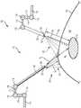
图1是根据本公开的至少一个方面的包括成像装置和外科装置的外科可视化系统的示意图,该外科可视化系统被配置成能够识别组织表面下方的关键结构。1 is a schematic diagram of a surgical visualization system including an imaging device and a surgical device, the surgical visualization system being configured to identify critical structures beneath a tissue surface, in accordance with at least one aspect of the present disclosure.
图2是根据本公开的至少一个方面的用于外科可视化系统的控制系统的示意图。2 is a schematic diagram of a control system for a surgical visualization system in accordance with at least one aspect of the present disclosure.
图2A示出了根据本公开的至少一个方面的被配置成能够控制外科可视化系统的各方面的控制电路。2A illustrates a control circuit configured to control various aspects of a surgical visualization system in accordance with at least one aspect of the present disclosure.
图2B示出了根据本公开的至少一个方面的被配置成能够控制外科可视化系统的各方面的组合逻辑电路。2B illustrates a combinational logic circuit configured to control various aspects of a surgical visualization system in accordance with at least one aspect of the present disclosure.
图2C示出了根据本公开的至少一个方面的被配置成能够控制外科可视化系统的各方面的时序逻辑电路。2C illustrates sequential logic circuitry configured to control various aspects of a surgical visualization system in accordance with at least one aspect of the present disclosure.
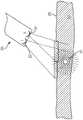
图3是根据本公开的至少一个方面的描绘在图1的外科装置、成像装置与关键结构之间进行三角测量以确定关键结构在组织表面下方的深度da的示意图。3 isa schematic diagram depicting triangulation between the surgical device, imaging device, and critical structures of FIG. 1 to determine the depth da of the critical structures below the tissue surface in accordance with at least one aspect of the present disclosure.
图4是根据本公开的至少一个方面的被配置成能够识别组织表面下方的关键结构的外科可视化系统的示意图,其中该外科可视化系统包括用于确定关键结构在组织表面下方的深度da的脉冲光源。4 is a schematic diagram ofa surgical visualization system configured to identify critical structures below the tissue surface, wherein the surgical visualization system includes pulses for determining the depth da of the critical structures below the tissue surface, in accordance with at least one aspect of the present disclosure light source.
图5是根据本公开的至少一个方面的包括成像装置和外科装置的外科可视化系统的示意图,该外科可视化系统被配置成能够识别组织表面下方的关键结构。5 is a schematic diagram of a surgical visualization system including an imaging device and a surgical device, the surgical visualization system being configured to identify critical structures beneath a tissue surface, in accordance with at least one aspect of the present disclosure.
图6是根据本公开的至少一个方面的包括三维相机的外科可视化系统的示意图,其中该外科可视化系统被配置成能够识别嵌入组织内的关键结构。6 is a schematic diagram of a surgical visualization system including a three-dimensional camera configured to identify critical structures embedded within tissue in accordance with at least one aspect of the present disclosure.
图7A和图7B是根据本公开的至少一个方面的由图6的三维相机拍摄的关键结构的视图,其中图7A是来自三维相机的左侧透镜的视图,并且图7B是来自三维相机的右侧透镜的视图。7A and 7B are views of key structures captured by the 3D camera of FIG. 6, wherein FIG. 7A is a view from a left lens of the 3D camera, and FIG. 7B is a view from a right lens of the 3D camera, according to at least one aspect of the present disclosure. View of the side lens.
图8是根据本公开的至少一个方面的图6的外科可视化系统的示意图,其中可确定从三维相机到关键结构的相机-关键结构距离dw。8 is a schematic diagram of the surgical visualization system of FIG. 6 in which a camera-critical structure distancedw from a three-dimensional camera to a critical structure may be determined in accordance with at least one aspect of the present disclosure.
图9是根据本公开的至少一个方面的利用两个相机来确定嵌入关键结构的方位的外科可视化系统的示意图。9 is a schematic diagram of a surgical visualization system utilizing two cameras to determine the orientation of embedded critical structures in accordance with at least one aspect of the present disclosure.
图10A是根据本公开的至少一个方面的利用相机的外科可视化系统的示意图,该相机在多个已知方位之间轴向运动以确定嵌入关键结构的方位。10A is a schematic diagram of a surgical visualization system utilizing a camera that is moved axially between a number of known orientations to determine orientations to embed critical structures in accordance with at least one aspect of the present disclosure.
图10B是根据本公开的至少一个方面的图10A的外科可视化系统的示意图,其中相机在多个已知方位之间轴向且旋转运动以确定嵌入关键结构的方位。10B is a schematic diagram of the surgical visualization system of FIG. 10A with the camera moving axially and rotationally between a number of known orientations to determine orientations to embed critical structures in accordance with at least one aspect of the present disclosure.
图11是根据本公开的至少一个方面的用于外科可视化系统的控制系统的示意图。11 is a schematic diagram of a control system for a surgical visualization system in accordance with at least one aspect of the present disclosure.
图12是根据本公开的至少一个方面的用于外科可视化系统的结构化光源的示意图。12 is a schematic diagram of a structured light source for a surgical visualization system in accordance with at least one aspect of the present disclosure.
图13A是根据本公开的至少一个方面的各种生物材料的吸收系数不同波长的曲线图。13A is a graph of the absorption coefficients of various biological materials at different wavelengths in accordance with at least one aspect of the present disclosure.
图13B是根据本公开的至少一个方面的通过光谱外科可视化系统对解剖结构进行可视化的示意图。13B is a schematic diagram of visualization of anatomical structures by a spectral surgical visualization system in accordance with at least one aspect of the present disclosure.
图13C至图13E描绘了根据本公开的至少一个方面的用于区分解剖结构与遮蔽物的例示性高光谱识别特征,其中图13C是输尿管特征与遮蔽物的图形表示,图13D是动脉特征与遮蔽物的图形表示,并且图13E是神经特征与遮蔽物的图形表示。13C-13E depict exemplary hyperspectral identification features for distinguishing anatomical structures from occlusions, wherein FIG. 13C is a graphical representation of ureteral features and occlusions, and FIG. 13D is an arterial feature with occlusions, in accordance with at least one aspect of the present disclosure. A graphical representation of the mask, and Figure 13E is a graphical representation of the neural features and the mask.
图14是根据本公开的至少一个方面的被配置成能够感测离关键解剖结构的距离的近红外(NIR)飞行时间测量系统的示意图,该飞行时间测量系统包括定位在公共装置上的传输器(发射器)和接收器(传感器)。14 is a schematic diagram of a near-infrared (NIR) time-of-flight measurement system configured to sense distance from critical anatomical structures, the time-of-flight measurement system including a transmitter positioned on a common device, in accordance with at least one aspect of the present disclosure (transmitter) and receiver (sensor).
图15是根据本公开的至少一个方面的图17A的NIR飞行时间测量系统的发射波、接收波以及发射波与接收波之间的延迟的示意图。15 is a schematic diagram of transmitted waves, received waves, and delays between the transmitted and received waves of the NIR time-of-flight measurement system of FIG. 17A in accordance with at least one aspect of the present disclosure.
图16示出了根据本公开的至少一个方面的被配置成能够感测离不同结构的距离的NIR飞行时间测量系统,该飞行时间测量系统包括单独装置上的传输器(发射器)和接收器(传感器)。16 illustrates a NIR time-of-flight measurement system including a transmitter (transmitter) and a receiver on separate devices configured to sense distance from different structures in accordance with at least one aspect of the present disclosure (sensor).
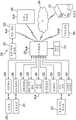
图17是根据本公开的至少一个方面的由计算机实现的交互式外科系统的框图。17 is a block diagram of a computer-implemented interactive surgical system in accordance with at least one aspect of the present disclosure.
图18是根据本公开的至少一个方面的用于在手术室中执行外科手术的外科系统。18 is a surgical system for performing a surgical procedure in an operating room in accordance with at least one aspect of the present disclosure.
图19示出了根据本公开的至少一个方面的由计算机实现的交互式外科系统。19 illustrates a computer-implemented interactive surgical system in accordance with at least one aspect of the present disclosure.
图20示出了根据本公开的至少一个方面的态势感知外科系统的图。20 shows a diagram of a situational awareness surgical system in accordance with at least one aspect of the present disclosure.
图21示出了根据本公开的至少一个方面的描绘集线器的态势感知的时间轴。21 illustrates a timeline depicting situational awareness of a hub in accordance with at least one aspect of the present disclosure.
图22是根据本公开的至少一个方面的过程的逻辑流程图,该逻辑流程图描绘了用于将可视化数据与仪器数据相关联的控制程序或逻辑配置。22 is a logic flow diagram of a process in accordance with at least one aspect of the present disclosure, the logic flow diagram depicting a control program or logic configuration for associating visualization data with instrument data.
图23是根据本公开的至少一个方面的外科器械的示意图。23 is a schematic illustration of a surgical instrument in accordance with at least one aspect of the present disclosure.
图24是描绘根据本公开的至少一个方面的复合数据集以及闭合力(“FTC”)和击发力(“FTF”)虚拟量规的曲线图。24 is a graph depicting a composite dataset and virtual gauges for closing force ("FTC") and firing force ("FTF") in accordance with at least one aspect of the present disclosure.
图25A示出了根据本公开的至少一个方面的可视化系统的屏幕的普通视图,该可视化系统显示了外科手术的外科视场中的端部执行器的实时馈送。25A shows a general view of a screen of a visualization system showing a real-time feed of an end effector in the surgical field of view of a surgical procedure, in accordance with at least one aspect of the present disclosure.
图25B示出了根据本公开的至少一个方面的可视化系统的屏幕的增强视图,该可视化系统显示了外科手术的外科视场中的端部执行器的实时馈送。25B illustrates an enhanced view of a screen of a visualization system showing a real-time feed of an end effector in a surgical field of view for a surgical procedure, according to at least one aspect of the present disclosure.
图26是根据本公开的至少一个方面的过程的逻辑流程图,该逻辑流程图描绘了使端部执行器部件的虚拟表示的运动与端部执行器部件的实际运动同步的控制程序或逻辑配置。26 is a logic flow diagram of a process in accordance with at least one aspect of the present disclosure, the logic flow diagram depicting a control program or logic configuration for synchronizing movement of a virtual representation of an end effector component with actual movement of the end effector component .
图27示出了根据本公开的至少一个方面的体壁和体壁下方的腔中的解剖结构,其中套管针穿过体壁进入腔中,并且屏幕显示套管针距解剖结构的距离、与通过套管针呈现外科器械相关的风险以及与此相关的估计操作时间。27 shows the anatomy of a body wall and a cavity below the body wall with a trocar passing through the body wall into the cavity and a screen showing the distance of the trocar from the anatomy, according to at least one aspect of the present disclosure, Risks associated with presenting surgical instruments through the trocar and estimated operating time associated therewith.
图28示出了根据本公开的至少一个方面的暴露于来自结构化光投影仪的结构化光的胃的虚拟三维(“3D”)构造。28 illustrates a virtual three-dimensional ("3D") configuration of a stomach exposed to structured light from a structured light projector in accordance with at least one aspect of the present disclosure.
图29是根据本公开的至少一个方面的过程的逻辑流程图,该逻辑流程图描绘了用于将可视化数据与仪器数据相关联的控制程序或逻辑配置,其中具有虚线的框表示该过程的替代具体实施。29 is a logic flow diagram of a process in accordance with at least one aspect of the present disclosure, the logic flow diagram depicting a control program or logic configuration for associating visualization data with instrument data, with boxes with dashed lines representing alternatives to the process specific implementation.
图30示出了根据本公开的至少一个方面的暴露于来自结构化光投影仪的结构化光的胃的虚拟3D构造。30 illustrates a virtual 3D construction of a stomach exposed to structured light from a structured light projector in accordance with at least one aspect of the present disclosure.
图31是根据本公开的至少一个方面的过程的逻辑流程图,该逻辑流程图描绘了用于给出移除解剖器官的一部分的切除路径的控制程序或逻辑配置,其中具有虚线的框表示该过程的替代具体实施。31 is a logic flow diagram of a process in accordance with at least one aspect of the present disclosure, the logic flow diagram depicting a control program or logic configuration for presenting a resection path for removing a portion of an anatomical organ, wherein a box with a dashed line represents the Alternative implementation of the process.
图32A示出了根据本公开的至少一个方面的在外科手术开始时可视化系统的屏幕上的外科视场的实时视图。32A shows a real-time view of the surgical field of view on the screen of the visualization system at the beginning of a surgical procedure, according to at least one aspect of the present disclosure.
图32B是根据本公开的至少一个方面的图32A的外科视场的一部分的放大视图,概述了叠加在该外科视场上的所给出的手术切除路径。32B is an enlarged view of a portion of the surgical field of view of FIG. 32A summarizing the presented surgical resection path superimposed on the surgical field of view, in accordance with at least one aspect of the present disclosure.
图32C示出了根据本公开的至少一个方面,在外科手术开始后四十三分钟时图32B的外科视场的实时视图。32C shows a real-time view of the surgical field of view of FIG. 32B at forty-three minutes after the start of a surgical procedure, in accordance with at least one aspect of the present disclosure.
图32D示出了根据本公开的至少一个方面的图32C的外科视场的放大视图,概述了对所给出的手术切除路径的修改。32D illustrates an enlarged view of the surgical field of view of FIG. 32C, outlining modifications to the presented surgical resection path, in accordance with at least one aspect of the present disclosure.
图33是根据本公开的至少一个方面的过程的逻辑流程图,该逻辑流程图描绘了用于将外科器械的参数呈现到所给出的手术切除路径上或附近的控制程序或逻辑配置,其中具有虚线的框表示该过程的替代具体实施。33 is a logic flow diagram of a process in accordance with at least one aspect of the present disclosure, the logic flow diagram depicting a control program or logic configuration for presenting parameters of a surgical instrument on or near a given surgical resection path, wherein Boxes with dashed lines represent alternative implementations of this process.
图34示出了根据本公开的至少一个方面的经历袖状胃切除术的患者的胃的虚拟3D构造。34 illustrates a virtual 3D construction of a stomach of a patient undergoing sleeve gastrectomy in accordance with at least one aspect of the present disclosure.
图35示出了图34的胃的完整虚拟切除。FIG. 35 shows a complete virtual resection of the stomach of FIG. 34 .
图36A至图36C示出了根据本公开的至少一个方面的外科缝合器械的击发。36A-36C illustrate firing of a surgical stapling instrument in accordance with at least one aspect of the present disclosure.
图37是根据本公开的至少一个方面的过程的逻辑流程图,该逻辑流程图描绘了用于调整外科器械的击发速度的控制程序或逻辑配置。37 is a logic flow diagram of a process in accordance with at least one aspect of the present disclosure, the logic flow diagram depicting a control routine or logic configuration for adjusting a firing rate of a surgical instrument.
图38是根据本公开的至少一个方面的过程的逻辑流程图,该逻辑流程图描绘了用于沿着所给出的手术切除路径的所给出的钉仓布置的控制程序或逻辑配置。38 is a logic flow diagram of a process in accordance with at least one aspect of the present disclosure, the logic flow diagram depicting a control program or logic configuration for a given staple cartridge placement along a given surgical resection path.
图39是根据本公开的至少一个方面的过程的逻辑流程图,该逻辑流程图描绘了用于给出器官部分的手术切除的控制程序或逻辑配置。39 is a logic flow diagram of a process in accordance with at least one aspect of the present disclosure, the logic flow diagram depicting a control program or logic configuration for giving surgical resection of an organ portion.
图40是根据本公开的至少一个方面的过程的逻辑流程图,该逻辑流程图描绘了用于估计由于移除器官的选定部分而导致的器官容量减少量的控制程序或逻辑配置。40 is a logic flow diagram of a process in accordance with at least one aspect of the present disclosure, the logic flow diagram depicting a control program or logic configuration for estimating an amount of organ volume reduction due to removal of a selected portion of an organ.
图41A示出了根据本公开的至少一个方面的暴露于结构化光的患者肺,包括在外科手术期间要被切除的部分。41A illustrates a patient's lung exposed to structured light, including a portion to be resected during surgery, in accordance with at least one aspect of the present disclosure.
图41B示出了根据本公开的至少一个方面的在切除该部分之后的图41A的患者肺。41B illustrates the patient's lung of FIG. 41A after the portion has been resected in accordance with at least one aspect of the present disclosure.
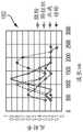
图41C示出了根据本公开的至少一个方面的在切除肺的该部分之前和之后测量来自图41A和图41B的患者肺的肺容量峰值的曲线图。41C shows a graph of peak lung volume measured from the patient's lung of FIGS. 41A and 41B before and after resection of the portion of the lung, according to at least one aspect of the present disclosure.
图42示出了根据本公开的至少一个方面的在切除肺的一部分之前、之后立即和之后一分钟测量患者肺中二氧化碳分压(“PCO2”)的曲线图。42 shows graphs measuring partial pressure of carbondioxide ("PCO2") in a patient's lung before, immediately after, and one minute after resection of a portion of the lung, according to at least one aspect of the present disclosure.
图43是根据本公开的至少一个方面的过程的逻辑流程图,该逻辑流程图描绘了用于使用可视化数据和非可视化数据检测组织异常的控制程序或逻辑配置。43 is a logic flow diagram of a process in accordance with at least one aspect of the present disclosure, the logic flow diagram depicting a control program or logic configuration for detecting tissue abnormalities using visualization data and non-visualization data.
图44A示出了根据本公开的至少一个方面的处于第一状态的右肺,其中成像装置将光的图案发射到其表面上。44A shows the right lung in a first state with the imaging device emitting a pattern of light onto its surface, according to at least one aspect of the present disclosure.
图44B示出了根据本公开的至少一个方面的处于第二状态的图44A的右肺,其中成像装置将光的图案发射到其表面上。44B illustrates the right lung of FIG. 44A in a second state with the imaging device emitting a pattern of light onto its surface in accordance with at least one aspect of the present disclosure.
图44C示出了根据本公开的至少一个方面的图44A的右肺的顶部部分。44C illustrates a top portion of the right lung of FIG. 44A in accordance with at least one aspect of the present disclosure.
图44D示出了根据本公开的至少一个方面的图44B的右肺的顶部部分。44D illustrates a top portion of the right lung of FIG. 44B in accordance with at least one aspect of the present disclosure.
具体实施方式Detailed ways
本申请的申请人拥有以下美国专利申请,这些专利申请中的每一项全文以引用方式并入本文:The applicant of the present application owns the following US patent applications, each of which is incorporated herein by reference in its entirety:
·代理人案卷号END9228USNP1/190580-1M,其名称为“METHOD OF USING IMAGINGDEVICES IN SURGERY”;·Attorney's file number END9228USNP1/190580-1M, its name is "METHOD OF USING IMAGINGDEVICES IN SURGERY";
·代理人案卷号END9227USNP1/190579-1,其名称为“ADAPTIVE VISUALIZATIONBY A SURGICAL SYSTEM”;·The agent's file number END9227USNP1/190579-1, its name is "ADAPTIVE VISUALIZATIONBY A SURGICAL SYSTEM";
·代理人案卷号END9226USNP1/190578-1,其名称为“SURGICAL SYSTEM CONTROLBASED ON MULTIPLE SENSED PARAMETERS”;·Attorney's file number END9226USNP1/190578-1, its name is "SURGICAL SYSTEM CONTROLBASED ON MULTIPLE SENSED PARAMETERS";
·代理人案卷号END9225USNP1/190577-1,其名称为“ADAPTIVE SURGICAL SYSTEMCONTROL ACCORDING TO SURGICAL SMOKE PARTICLE CHARACTERISTICS”;·Attorney's file number END9225USNP1/190577-1, its name is "ADAPTIVE SURGICAL SYSTEMCONTROL ACCORDING TO SURGICAL SMOKE PARTICLE CHARACTERISTICS";
·代理人案卷号END9224USNP1/190576-1,其名称为“ADAPTIVE SURGICAL SYSTEMCONTROL ACCORDING TO SURGICAL SMOKE CLOUD CHARACTERISTICS”;·Attorney's file number END9224USNP1/190576-1, its name is "ADAPTIVE SURGICAL SYSTEMCONTROL ACCORDING TO SURGICAL SMOKE CLOUD CHARACTERISTICS";
·代理人案卷号END9223USNP1/190575-1,其名称为“SURGICAL SYSTEMSCORRELATING VISUALIZATION DATA AND POWERED SURGICAL INSTRUMENT DATA”;·Attorney's file number END9223USNP1/190575-1, its name is "SURGICAL SYSTEMSCORRELATING VISUALIZATION DATA AND POWERED SURGICAL INSTRUMENT DATA";
·代理人案卷号END9222USNP1/190574-1,其名称为“SURGICAL SYSTEMS FORGENERATING THREE DIMENSIONAL CONSTRUCTS OF ANATOMICAL ORGANS AND COUPLINGIDENTIFIED”;·Attorney's file number END9222USNP1/190574-1, its name is "SURGICAL SYSTEMS FORGENERATING THREE DIMENSIONAL CONSTRUCTS OF ANATOMICAL ORGANS AND COUPLINGIDENTIFIED";
·代理人案卷号END9221USNP1/190573-1,其名称为“SURGICAL SYSTEM FOROVERLAYING SURGICAL INSTRUMENT DATA ONTO A VIRTUAL THREE DIMENSIONALCONSTRUCT OF AN ORGAN”;·Attorney's file number END9221USNP1/190573-1, its name is "SURGICAL SYSTEM FOROVERLAYING SURGICAL INSTRUMENT DATA ONTO A VIRTUAL THREE DIMENSIONAL CONSTRUCT OF AN ORGAN";
·代理人案卷号END9219USNP1/190571-1,其名称为“SYSTEM AND METHOD FORDETERMINING,ADJUSTING,AND MANAGING RESECTION MARGIN ABOUT A SUBJECT TISSUE”;·Attorney's file number END9219USNP1/190571-1, its name is "SYSTEM AND METHOD FORDETERMINING, ADJUSTING, AND MANAGING RESECTION MARGIN ABOUT A SUBJECT TISSUE";
·代理人案卷号END9218USNP1/190570-1,其名称为“VISUALIZATION SYSTEMSUSING STRUCTURED LIGHT”;·Attorney's file number END9218USNP1/190570-1, its name is "VISUALIZATION SYSTEMSUSING STRUCTURED LIGHT";
·代理人案卷号END9217USNP1/190569-1,其名称为“DYNAMIC SURGICALVISUALIZATION SYSTEMS”;以及Attorney's docket number END9217USNP1/190569-1, which is named "DYNAMIC SURGICALVISUALIZATION SYSTEMS"; and
·代理人案卷号END9216USNP1/190568-1,其名称为“ANALYZING SURGICALTRENDS BY A SURGICAL SYSTEM”。·Attorney's file number END9216USNP1/190568-1, its name is "ANALYZING SURGICALTRENDS BY A SURGICAL SYSTEM".
本申请的申请人拥有于2019年3月15日提交的以下美国专利申请,这些专利申请中的每一项全文以引用方式并入本文:The applicant of the present application has the following US patent applications filed on March 15, 2019, each of which is incorporated herein by reference in its entirety:
·美国专利申请序列号16/354,417,其名称为“INPUT CONTROLS FOR ROBOTICSURGERY”;U.S. Patent Application Serial No. 16/354,417, entitled "INPUT CONTROLS FOR ROBOTICSURGERY";
·美国专利申请序列号16/354,420,其名称为“DUAL MODE CONTROLS FORROBOTIC SURGERY”;U.S. Patent Application Serial No. 16/354,420 entitled "DUAL MODE CONTROLS FORROBOTIC SURGERY";
·美国专利申请序列号16/354,422,其名称为“MOTION CAPTURE CONTROLS FORROBOTIC SURGERY”;U.S. Patent Application Serial No. 16/354,422, entitled "MOTION CAPTURE CONTROLS FORROBOTIC SURGERY";
·美国专利申请序列号16/354,440,其名称为“ROBOTIC SURGICAL SYSTEMS WITHMECHANISMS FOR SCALING SURGICAL TOOL MOTION ACCORDING TO TISSUE PROXIMITY”;U.S. Patent Application Serial No. 16/354,440, entitled "ROBOTIC SURGICAL SYSTEMS WITHMECHANISMS FOR SCALING SURGICAL TOOL MOTION ACCORDING TO TISSUE PROXIMITY";
·美国专利申请序列号16/354,444,其名称为“ROBOTIC SURGICAL SYSTEMS WITHMECHANISMS FOR SCALING CAMERA MAGNIFICATION ACCORDING TO PROXIMITY OFSURGICAL TOOL TO TISSUE”;U.S. Patent Application Serial No. 16/354,444, entitled "ROBOTIC SURGICAL SYSTEMS WITHMECHANISMS FOR SCALING CAMERA MAGNIFICATION ACCORDING TO PROXIMITY OFSURGICAL TOOL TO TISSUE";
·美国专利申请序列号16/354,454,其名称“ROBOTIC SURGICAL SYSTEMS WITHSELECTIVELY LOCKABLE END EFFECTORS”;U.S. Patent Application Serial No. 16/354,454, entitled "ROBOTIC SURGICAL SYSTEMS WITHSELECTIVELY LOCKABLE END EFFECTORS";
·美国专利申请序列号16/354,461,其名称为“SELECTABLE VARIABLE RESPONSEOF SHAFT MOTION OF SURGICAL ROBOTIC SYSTEMS”;U.S. Patent Application Serial No. 16/354,461, entitled "SELECTABLE VARIABLE RESPONSEOF SHAFT MOTION OF SURGICAL ROBOTIC SYSTEMS";
·美国专利申请序列号16/354,470,其名称为“SEGMENTED CONTROL INPUTS FORSURGICAL ROBOTIC SYSTEMS”;U.S. Patent Application Serial No. 16/354,470, entitled "SEGMENTED CONTROL INPUTS FORSURGICAL ROBOTIC SYSTEMS";
·美国专利申请序列号16/354,474,其名称为“ROBOTIC SURGICAL CONTROLSHAVING FEEDBACK CAPABILITIES”;U.S. Patent Application Serial No. 16/354,474, entitled "ROBOTIC SURGICAL CONTROLSHAVING FEEDBACK CAPABILITIES";
·美国专利申请序列号16/354,478,其名称“ROBOTIC SURGICAL CONTROLS WITHFORCE FEEDBACK”;以及U.S. Patent Application Serial No. 16/354,478, entitled "ROBOTIC SURGICAL CONTROLS WITHFORCE FEEDBACK"; and
·美国专利申请序列号16/354,481,其名称为“JAW COORDINATION OF ROBOTICSURGICAL CONTROLS”。- US Patent Application Serial No. 16/354,481 entitled "JAW COORDINATION OF ROBOTICSURGICAL CONTROLS".
本申请的申请人还拥有2018年9月11日提交的以下美国专利申请,这些专利申请中的每一项全文以引用方式并入本文:The applicant of the present application also owns the following US patent applications filed on September 11, 2018, each of which is incorporated herein by reference in its entirety:
·美国专利申请序列号16/128,179,其名称为“SURGICAL VISUALIZATIONPLATFORM”;U.S. Patent Application Serial No. 16/128,179, entitled "SURGICAL VISUALIZATION PLATFORM";
·美国专利申请序列号16/128,180,其名称为为“CONTROLLING AN EMITTERASSEMBLY PULSE SEQUENCE”;U.S. Patent Application Serial No. 16/128,180, entitled "CONTROLLING AN EMITTERASSEMBLY PULSE SEQUENCE";
·美国专利申请序列号16/128,198,其名称为“SINGULAR EMR SOURCE EMITTERASSEMBLY”;U.S. Patent Application Serial No. 16/128,198 entitled "SINGULAR EMR SOURCE EMITTERASSEMBLY";
·美国专利申请序列号16/128,207,其名称为“COMBINATION EMITTER ANDCAMERA ASSEMBLY”;U.S. Patent Application Serial No. 16/128,207 entitled "COMBINATION EMITTER ANDCAMERA ASSEMBLY";
·美国专利申请序列号16/128,176,其名称为“SURGICAL VISUALIZATION WITHPROXIMITY TRACKING FEATURES”;U.S. Patent Application Serial No. 16/128,176, entitled "SURGICAL VISUALIZATION WITHPROXIMITY TRACKING FEATURES";
·美国专利申请序列号16/128,187,其名称为“SURGICAL VISUALIZATION OFMULTIPLE TARGETS”;U.S. Patent Application Serial No. 16/128,187, entitled "SURGICAL VISUALIZATION OFMULTIPLE TARGETS";
·美国专利申请序列号16/128,192,其名称为“VISUALIZATION OF SURGICALDEVICES”;U.S. Patent Application Serial No. 16/128,192, entitled "VISUALIZATION OF SURGICAL DEVICES";
·美国专利申请序列号16/128,163,其名称为“OPERATIVE COMMUNICATION OFLIGHT”;U.S. Patent Application Serial No. 16/128,163, entitled "OPERATIVE COMMUNICATION OFLIGHT";
·美国专利申请序列号16/128,197,其名称为“ROBOTIC LIGHT PROJECTIONTOOLS”;U.S. Patent Application Serial No. 16/128,197, entitled "ROBOTIC LIGHT PROJECTIONTOOLS";
·美国专利申请序列号16/128,164,其名称为“SURGICAL VISUALIZATIONFEEDBACK SYSTEM”;U.S. Patent Application Serial No. 16/128,164, entitled "SURGICAL VISUALIZATION FEEDBACK SYSTEM";
·美国专利申请序列号16/128,193,其名称为“SURGICAL VISUALIZATION ANDMONITORING”;U.S. Patent Application Serial No. 16/128,193, entitled "SURGICAL VISUALIZATION ANDMONITORING";
·美国专利申请序列号16/128,195,其名称为“INTEGRATION OF IMAGING DATA”;U.S. Patent Application Serial No. 16/128,195, entitled "INTEGRATION OF IMAGING DATA";
·美国专利申请序列号16/128,170,其名称为“ROBOTICALLY-ASSISTED SURGICALSUTURING SYSTEMS”;U.S. Patent Application Serial No. 16/128,170, entitled "ROBOTICALLY-ASSISTED SURGICALSUTURING SYSTEMS";
·美国专利申请序列号16/128,183,其名称为“SAFETY LOGIC FOR SURGICALSUTURING SYSTEMS”;U.S. Patent Application Serial No. 16/128,183, entitled "SAFETY LOGIC FOR SURGICAL SUTURING SYSTEMS";
·美国专利申请序列号16/128,172,其名称为“ROBOTIC SYSTEM WITH SEPARATEPHOTOACOUSTIC RECEIVER”;以及U.S. Patent Application Serial No. 16/128,172, entitled "ROBOTIC SYSTEM WITH SEPARATEPHOTOACOUSTIC RECEIVER"; and
·美国专利申请序列号16/128,185,其名称为“FORCE SENSOR THROUGHSTRUCTURED LIGHT DEFLECTION”。- US Patent Application Serial No. 16/128,185 entitled "FORCE SENSOR THROUGHSTRUCTURED LIGHT DEFLECTION".
本申请的申请人还拥有2018年3月29日提交的以下美国专利申请,这些专利申请中的每一项全文以引用方式并入本文:The applicant of the present application also owns the following US patent applications filed on March 29, 2018, each of which is incorporated herein by reference in its entirety:
·美国专利申请序列号15/940,627,其名称为“DRIVE ARRANGEMENTS FOR ROBOT-ASSISTED SURGICAL PLATFORMS”,现为美国专利申请公开号2019/0201111;U.S. Patent Application Serial No. 15/940,627, entitled "DRIVE ARRANGEMENTS FOR ROBOT-ASSISTED SURGICAL PLATFORMS", now U.S. Patent Application Publication No. 2019/0201111;
·美国专利申请序列号15/940,676,其名称为“AUTOMATIC TOOL ADJUSTMENTSFOR ROBOT-ASSISTED SURGICAL PLATFORMS”,现为美国专利申请公开号2019/0201142;U.S. Patent Application Serial No. 15/940,676, entitled "AUTOMATIC TOOL ADJUSTMENTSFOR ROBOT-ASSISTED SURGICAL PLATFORMS", now U.S. Patent Application Publication No. 2019/0201142;
·美国专利申请序列号15/940,711,其名称为“SENSING ARRANGEMENTS FORROBOT-ASSISTED SURGICAL PLATFORMS”,现为美国专利申请公开号2019/0201120;以及U.S. Patent Application Serial No. 15/940,711, entitled "SENSING ARRANGEMENTS FORROBOT-ASSISTED SURGICAL PLATFORMS," now U.S. Patent Application Publication No. 2019/0201120; and
·美国专利申请序列号15/940,722,其名称为“CHARACTERIZATION OF TISSUEIRREGULARITIES THROUGH THE USE OF MONO-CHROMATIC LIGHT REFRACTIVITY”,现为美国专利申请公开号2019/0200905。· US Patent Application Serial No. 15/940,722 entitled "CHARACTERIZATION OF TISSUEIRREGULARITIES THROUGH THE USE OF MONO-CHROMATIC LIGHT REFRACTIVITY", now US Patent Application Publication No. 2019/0200905.
本专利申请的申请人拥有于2018年12月4日提交的以下美国专利申请,这些临时专利申请中的每个的公开内容全文以引用方式并入本文:The applicant of the present patent application has the following US patent applications filed on December 4, 2018, the disclosures of each of these provisional patent applications are hereby incorporated by reference in their entirety:
·美国专利申请序列号16/209,395,其名称为“METHOD OF HUB COMMUNICATION”,现为美国专利申请公开号2019/0201136;U.S. Patent Application Serial No. 16/209,395, entitled "METHOD OF HUB COMMUNICATION", now U.S. Patent Application Publication No. 2019/0201136;
·美国专利申请序列号16/209,403,其名称为“METHOD OF CLOUD BASED DATAANALYTICS FOR USE WITH THE HUB”,现为美国专利申请公开号2019/0206569;U.S. Patent Application Serial No. 16/209,403, titled "METHOD OF CLOUD BASED DATAANALYTICS FOR USE WITH THE HUB", now U.S. Patent Application Publication No. 2019/0206569;
·美国专利申请序列号16/209,407,其名称为“METHOD OF ROBOTIC HUBCOMMUNICATION,DETECTION,AND CONTROL”,现为美国专利申请公开号2019/0201137;U.S. Patent Application Serial No. 16/209,407, titled "METHOD OF ROBOTIC HUBCOMMUNICATION, DETECTION, AND CONTROL", now U.S. Patent Application Publication No. 2019/0201137;
·美国专利申请序列号16/209,416,其名称为“METHOD OF HUB COMMUNICATION,PROCESSING,DISPLAY,AND CLOUD ANALYTICS”,现为美国专利申请公开号2019/0206562;U.S. Patent Application Serial No. 16/209,416, entitled "METHOD OF HUB COMMUNICATION, PROCESSING, DISPLAY, AND CLOUD ANALYTICS", now U.S. Patent Application Publication No. 2019/0206562;
·美国专利申请序列号16/209,423,其名称为“METHOD OF COMPRESSING TISSUEWITHIN A STAPLING DEVICE AND SIMULTANEOUSLY DISPLAYING THE LOCATION OF THETISSUE WITHIN THE JAWS”,现为美国专利申请公开号2019/0200981;U.S. Patent Application Serial No. 16/209,423, titled "METHOD OF COMPRESSING TISSUEWITHIN A STAPLING DEVICE AND SIMULTANEOUSLY DISPLAYING THE LOCATION OF THETISSUE WITHIN THE JAWS", now U.S. Patent Application Publication No. 2019/0200981;
·美国专利申请序列号16/209,427,其名称为“METHOD OF USING REINFORCEDFLEXIBLE CIRCUITS WITH MULTIPLE SENSORS TO OPTIMIZE PERFORMANCE OF RADIOFREQUENCY DEVICES”,现为美国专利申请公开号2019/0208641;U.S. Patent Application Serial No. 16/209,427, entitled "METHOD OF USING REINFORCEDFLEXIBLE CIRCUITS WITH MULTIPLE SENSORS TO OPTIMIZE PERFORMANCE OF RADIOFREQUENCY DEVICES", now U.S. Patent Application Publication No. 2019/0208641;
·美国专利申请序列号16/209,433,其名称为“METHOD OF SENSING PARTICULATEFROM SMOKE EVACUATED FROM A PATIENT,ADJUSTING THE PUMP SPEED BASED ON THESENSED INFORMATION,AND COMMUNICATING THE FUNCTIONAL PARAMETERS OF THE SYSTEMTO THE HUB”,现为美国专利申请公开号2019/0201594;U.S. Patent Application Serial No. 16/209,433, entitled "METHOD OF SENSING PARTICULATEFROM SMOKE EVACUATED FROM A PATIENT, ADJUSTING THE PUMP SPEED BASED ON THESENSED INFORMATION, AND COMMUNICATING THE FUNCTIONAL PARAMETERS OF THE SYSTEMTO THE HUB", now a U.S. patent application Publication No. 2019/0201594;
·美国专利申请序列号16/209,447,其名称为“METHOD FOR SMOKE EVACUATIONFOR SURGICAL HUB”,现为美国专利申请公开号2019/0201045;U.S. Patent Application Serial No. 16/209,447, titled "METHOD FOR SMOKE EVACUATIONFOR SURGICAL HUB", now U.S. Patent Application Publication No. 2019/0201045;
·美国专利申请序列号16/209,453,其名称为“METHOD FOR CONTROLLING SMARTENERGY DEVICES”,现为美国专利申请公开号2019/0201046;U.S. Patent Application Serial No. 16/209,453, entitled "METHOD FOR CONTROLLING SMARTENERGY DEVICES", now U.S. Patent Application Publication No. 2019/0201046;
·美国专利申请序列号16/209,458,其名称为“METHOD FOR SMART ENERGYDEVICE INFRASTRUCTURE”,现为美国专利申请公开号2019/0201047;U.S. Patent Application Serial No. 16/209,458, entitled "METHOD FOR SMART ENERGYDEVICE INFRASTRUCTURE", now U.S. Patent Application Publication No. 2019/0201047;
·美国专利申请序列号16/209,465,其名称为“METHOD FOR ADAPTIVE CONTROLSCHEMES FOR SURGICAL NETWORK CONTROL AND INTERACTION”,现为美国专利申请公开号2019/0206563;U.S. Patent Application Serial No. 16/209,465, entitled "METHOD FOR ADAPTIVE CONTROLSCHEMES FOR SURGICAL NETWORK CONTROL AND INTERACTION", now U.S. Patent Application Publication No. 2019/0206563;
·美国专利申请序列号16/209,478,其名称为“METHOD FOR SITUATIONALAWARENESS FOR SURGICAL NETWORK OR SURGICAL NETWORK CONNECTED DEVICE CAPABLEOF ADJUSTING FUNCTION BASED ON A SENSED SITUATION OR USAGE”,现为美国专利申请公开号2019/0104919;U.S. Patent Application Serial No. 16/209,478, entitled "METHOD FOR SITUATIONALAWARENESS FOR SURGICAL NETWORK OR SURGICAL NETWORK CONNECTED DEVICE CAPABLEOF ADJUSTING FUNCTION BASED ON A SENSED SITUATION OR USAGE", now U.S. Patent Application Publication No. 2019/0104919;
·美国专利申请序列号16/209,490,其名称为“METHOD FOR FACILITY DATACOLLECTION AND INTERPRETATION”,现为美国专利申请公开号2019/0206564;以及U.S. Patent Application Serial No. 16/209,490, entitled "METHOD FOR FACILITY DATACOLLECTION AND INTERPRETATION," now U.S. Patent Application Publication No. 2019/0206564; and
·美国专利申请序列号16/209,491,其名称为“METHOD FOR CIRCULAR STAPLERCONTROL ALGORITHM ADJUSTMENT BASED ON SITUATIONAL AWARENESS”,现为美国专利申请公开号2019/0200998。· US Patent Application Serial No. 16/209,491, entitled "METHOD FOR CIRCULAR STAPLERCONTROL ALGORITHM ADJUSTMENT BASED ON SITUATIONAL AWARENESS", now US Patent Application Publication No. 2019/0200998.
在详细说明外科可视化平台的各个方面之前,应当指出,例示性示例在应用或使用上不限于附图和说明书中所示出的部件的构造和布置的细节。例示性示例可在其他方面、变型和修改中实现或并入,并且可以各种方式实践或执行。此外,除非另外指明,否则本文所用的术语和表达是为了方便读者而对例示性示例进行描述而所选的,并非为了限制性的目的。而且,应当理解,以下描述的方面、方面的表达和/或示例中的一者或多者可与其他以下描述的方面、方面的表达和/或示例中的任何一者或多者组合。Before describing various aspects of the surgical visualization platform in detail, it should be noted that the illustrative examples are not limited in application or use to the details of construction and arrangement of components shown in the drawings and description. The illustrative examples may be implemented or incorporated in other aspects, variations and modifications, and may be practiced or carried out in various ways. Furthermore, unless otherwise indicated, the terminology and expressions used herein have been chosen for the convenience of the reader to describe illustrative examples and are not for the purpose of limitation. Furthermore, it should be understood that one or more of the aspects, expressions and/or examples of aspects described below may be combined with any one or more of the other aspects, expressions and/or examples of aspects described below.
外科可视化系统Surgical Visualization System
本公开涉及一种外科可视化平台,该外科可视化平台利用“数字外科手术”来获得关于患者的解剖结构和/或外科手术的附加信息。该外科可视化平台被进一步配置成能够以有帮助的方式将数据和/或信息传达给一个或多个临床医生。例如,本公开的各个方面提供了患者的解剖结构和/或外科手术的改善的可视化。The present disclosure relates to a surgical visualization platform that utilizes "digital surgery" to obtain additional information about a patient's anatomy and/or surgical procedures. The surgical visualization platform is further configured to communicate data and/or information to one or more clinicians in a helpful manner. For example, various aspects of the present disclosure provide for improved visualization of a patient's anatomy and/or surgery.
“数字外科手术”可涵盖机器人系统、高级成像、高级仪器、人工智能、机器学习、用于性能跟踪和基准测试的数据分析、手术室(OR)内部和外部两者的连接性以及更多。尽管本文所述的各种外科可视化平台可与机器人外科系统结合使用,但是外科可视化平台不限于与机器人外科系统一起使用。在某些情况下,高级外科可视化可在没有机器人以及/或者具有有限的和/或任选的机器人辅助的情况下进行。类似地,数字外科可在没有机器人以及/或者具有有限的和/或任选的机器人辅助的情况下进行。"Digital surgery" can encompass robotic systems, advanced imaging, advanced instrumentation, artificial intelligence, machine learning, data analytics for performance tracking and benchmarking, connectivity both inside and outside the operating room (OR), and more. Although the various surgical visualization platforms described herein can be used in conjunction with robotic surgical systems, surgical visualization platforms are not limited to use with robotic surgical systems. In some cases, advanced surgical visualization can be performed without robotics and/or with limited and/or optional robotic assistance. Similarly, digital surgery can be performed without robotics and/or with limited and/or optional robotic assistance.
在某些情况下,结合有外科可视化平台的外科系统可实现智能解剖以便识别和避开关键结构。关键结构包括解剖结构诸如输尿管、动脉诸如肠系膜上动脉、静脉诸如门静脉、神经诸如膈神经和/或肿瘤等解剖结构。在其他情况下,关键结构可以是例如解剖场中的外来结构,诸如外科装置、外科紧固件、夹具、大头钉、探条、带和/或板。关键结构可基于不同患者和/或不同手术来确定。本文还描述了示例性关键结构。例如,智能解剖技术可提供用于解剖的改善的术中指导,并且/或者可利用关键解剖结构检测和避开技术来实现智能决策。In some cases, surgical systems incorporating surgical visualization platforms can enable intelligent dissection to identify and avoid critical structures. Critical structures include anatomical structures such as ureters, arteries such as the superior mesenteric artery, veins such as the portal vein, nerves such as the phrenic nerve and/or tumors. In other cases, critical structures may be, for example, foreign structures in the anatomical field, such as surgical devices, surgical fasteners, clips, tacks, probes, straps, and/or plates. Critical structures can be determined on a patient-by-patient and/or by-operate basis. Exemplary key structures are also described herein. For example, intelligent anatomy techniques can provide improved intraoperative guidance for anatomy and/or can utilize key anatomical structure detection and avoidance techniques to enable intelligent decision making.
结合有外科可视化平台的外科系统还可实现智能吻合技术,该智能吻合技术利用改善的工作流程在最佳位置处提供更一致的吻合。也可利用本文所述的各种外科可视化平台和手术来改善癌症定位技术。例如,癌症定位技术可识别和跟踪癌症位置、取向及其边界。在某些情况下,癌症定位技术可在外科手术期间补偿工具、患者和/或患者的解剖结构的移动,以便为临床医生提供回到感兴趣的点的指导。Surgical systems combined with surgical visualization platforms also enable smart anastomosis technology that utilizes improved workflow to provide more consistent anastomosis at optimal locations. Cancer localization techniques can also be improved using the various surgical visualization platforms and procedures described herein. For example, cancer localization technology identifies and tracks cancer location, orientation, and its boundaries. In some cases, cancer localization techniques can compensate for movement of the tool, the patient, and/or the patient's anatomy during surgery in order to provide the clinician with guidance back to the point of interest.
在本公开的某些方面,外科可视化平台可提供改善的组织表征和/或淋巴结诊断和标测。例如,组织表征技术可在不需要物理触觉的情况下表征组织类型和健康,特别是当在组织内解剖和/或放置缝合装置时。本文所述的某些组织表征技术可在没有电离辐射和/或造影剂的情况下使用。关于淋巴结诊断和标测,外科可视化平台可在术前定位、标测和理想地诊断涉及例如癌性诊断和分期的淋巴系统和/或淋巴结。In certain aspects of the present disclosure, surgical visualization platforms can provide improved tissue characterization and/or lymph node diagnosis and mapping. For example, tissue characterization techniques can characterize tissue type and health without the need for physical touch, particularly when dissecting and/or placing suturing devices within tissue. Certain tissue characterization techniques described herein can be used without ionizing radiation and/or contrast agents. With regard to lymph node diagnosis and mapping, the surgical visualization platform can preoperatively locate, map and ideally diagnose the lymphatic system and/or lymph nodes involved, for example, in cancer diagnosis and staging.
在外科手术期间,临床医生可经由“肉眼”和/或成像系统获得的信息可提供外科部位的不完整视图。例如,某些结构(诸如嵌入或掩埋在器官内的结构)可至少部分地被隐蔽或隐藏起来使其不被看见。另外,某些尺寸和/或相对距离可能难以利用现有的传感器系统探知和/或难以让“肉眼”感知。此外,某些结构可在术前(例如,在外科手术之前但在术前扫描之后)和/或术中运动。在此类情况下,临床医生可能无法在术中准确地确定关键结构的位置。During a surgical procedure, information available to a clinician via "the naked eye" and/or an imaging system may provide an incomplete view of the surgical site. For example, certain structures, such as those embedded or buried within an organ, may be at least partially concealed or hidden from view. Additionally, certain dimensions and/or relative distances may be difficult to detect with existing sensor systems and/or difficult to perceive "with the naked eye". Additionally, certain structures may be moved preoperatively (eg, prior to surgery but after a preoperative scan) and/or intraoperatively. In such cases, clinicians may not be able to accurately locate critical structures intraoperatively.
当关键结构的方位不确定时和/或当关键结构与外科工具之间的接近度未知时,临床医生的决策过程可能受到阻碍。例如,临床医生可避开某些区域,以便避免意外解剖关键结构;然而,所避开的区域可能不必要地较大和/或至少部分地错位。由于不确定性和/或过于/过度谨慎操作,临床医生可能无法进入某些期望的区域。例如,过度谨慎可能导致临床医生留下肿瘤和/或其他不期望的组织的一部分,以企图避开关键结构,即使关键结构不在该特定区域中和/或不会受到在该特定区域中工作的临床医生的负面影响。在某些情况下,可通过增加知识和/或确定性来改善外科结果,这可使得外科医生在特定解剖区域方面更加准确,并且在某些情况下,使得外科医生不那么保守/更有进取性。When the orientation of critical structures is uncertain and/or when the proximity between critical structures and the surgical tool is unknown, the clinician's decision-making process may be hindered. For example, a clinician may avoid certain areas in order to avoid accidental dissection of critical structures; however, the avoided areas may be unnecessarily large and/or at least partially misplaced. Clinicians may not be able to access certain desired areas due to uncertainty and/or over/overcautious manipulation. For example, excessive caution may lead clinicians to leave behind a portion of tumor and/or other undesired tissue in an attempt to avoid critical structures even though critical structures are not in and/or are not subject to work in that particular area Negative impact on clinicians. In some cases, surgical outcomes may be improved by increasing knowledge and/or certainty, which may allow surgeons to be more accurate in specific anatomical regions and, in some cases, make surgeons less conservative/aggressive sex.
在各个方面,本公开提供了用于术中识别和避开关键结构的外科可视化系统。在一个方面,本公开提供了一种外科可视化系统,该外科可视化系统实现了加强的术中决策和改善的外科结果。在各个方面,所公开的外科可视化系统提供了高级可视化能力,超出临床医生用“肉眼”所见的内容以及/或者超出成像系统可识别和/或传达给临床医生的内容。各种外科可视化系统可增强和加强临床医生在组织治疗(例如,解剖)之前能够知道的内容,并且因此可在各种情况下改善结果。In various aspects, the present disclosure provides a surgical visualization system for intraoperative identification and avoidance of critical structures. In one aspect, the present disclosure provides a surgical visualization system that enables enhanced intraoperative decision-making and improved surgical outcomes. In various aspects, the disclosed surgical visualization system provides advanced visualization capabilities beyond what a clinician can see "with the naked eye" and/or beyond what an imaging system can recognize and/or convey to a clinician. Various surgical visualization systems can enhance and enhance what a clinician can know prior to tissue treatment (eg, anatomy), and thus can improve outcomes in various situations.
例如,可视化系统可包括被配置成能够发射多个光谱波的第一光发射器、被配置成能够发射光图案的第二光发射器以及被配置成能够检测可见光、对光谱波的分子响应(光谱成像)和/或光图案的一个或多个接收器或传感器。应该注意的是,在下面的整个公开内容中,除非特别提到可见光,否则任何提到的“光”可以包括电磁辐射(EMR)或EMR波长光谱的可见和/或不可见部分中的光子。外科可视化系统还可包括成像系统以及与接收器和成像系统信号通信的控制电路。基于来自接收器的输出,控制电路可确定外科部位处可见表面的几何表面标测图(即三维表面形貌)以及相对于外科部位的一个或多个距离。在某些情况下,控制电路可确定到至少部分隐蔽的结构的一个或多个距离。此外,成像系统可将几何表面标测图和一个或多个距离传达给临床医生。在此类情况下,提供给临床医生的外科部位的增强视图可提供外科部位的相关环境内的隐蔽结构的表示。例如,成像系统可在隐蔽和/或阻挡组织的几何表面标测图上虚拟地增强隐蔽结构,类似于在地面上绘制的线以指示表面下方的实用线。另外或另选地,成像系统可传达一个或多个外科工具与可见的阻挡组织和/或与至少部分隐蔽的结构的接近度以及/或者隐蔽结构在阻挡组织的可见表面下方的深度。例如,可视化系统可确定相对于可见组织的表面上的增强线的距离,并且将该距离传达到成像系统。For example, a visualization system may include a first light emitter configured to emit a plurality of spectral waves, a second light emitter configured to emit patterns of light, and a second light emitter configured to detect visible light, molecular responses to the spectral waves ( Spectral imaging) and/or one or more receivers or sensors for light patterns. It should be noted that throughout the disclosure below, unless visible light is specifically mentioned, any reference to "light" may include electromagnetic radiation (EMR) or photons in the visible and/or invisible portion of the EMR wavelength spectrum. The surgical visualization system may also include an imaging system and a control circuit in signal communication with the receiver and the imaging system. Based on the output from the receiver, the control circuit may determine a geometric surface map (ie, a three-dimensional surface topography) of the visible surface at the surgical site and one or more distances relative to the surgical site. In some cases, the control circuit may determine one or more distances to the at least partially concealed structure. Additionally, the imaging system can communicate the geometric surface map and one or more distances to the clinician. In such cases, the enhanced view of the surgical site provided to the clinician may provide a representation of hidden structures within the relevant environment of the surgical site. For example, the imaging system can virtually enhance occult structures on a geometric surface map of occult and/or blocking tissue, similar to lines drawn on the ground to indicate utility lines below the surface. Additionally or alternatively, the imaging system may communicate the proximity of the one or more surgical tools to the visible blocking tissue and/or to the at least partially concealed structure and/or the depth of the concealed structure below the visible surface of the blocking tissue. For example, the visualization system may determine the distance to the enhancement line on the surface of the visible tissue and communicate the distance to the imaging system.
在本公开的各个方面,公开了用于术中识别和避开关键结构的外科可视化系统。此类外科可视化系统可在外科手术期间向临床医生提供有价值的信息。因此,例如,临床医生知道外科可视化系统正在跟踪例如可在解剖期间接近的关键结构(诸如输尿管、特定神经和/或关键血管),可在整个外科手术过程中确信地保持动力。在一个方面,外科可视化系统可在足够长的时间内向临床医生提供指示,以使临床医生暂停和/或减慢外科手术并且评估与关键结构的接近度,以防止对其造成意外损坏。外科可视化系统可向临床医生提供理想的、优化的和/或可定制的信息量,以允许临床医生确信地和/或快速地运动穿过组织,同时避免对健康组织和/或关键结构造成意外损坏,并且因此最小化由外科手术引起的伤害风险。In various aspects of the present disclosure, surgical visualization systems for intraoperative identification and avoidance of critical structures are disclosed. Such surgical visualization systems can provide clinicians with valuable information during surgical procedures. Thus, for example, the clinician can confidently maintain momentum throughout the surgical procedure knowing that the surgical visualization system is tracking critical structures accessible during dissection, for example, such as ureters, certain nerves, and/or critical blood vessels. In one aspect, the surgical visualization system can provide instructions to the clinician long enough to allow the clinician to pause and/or slow down the surgical procedure and assess proximity to critical structures to prevent accidental damage thereto. Surgical visualization systems can provide clinicians with an ideal, optimized and/or customizable amount of information to allow clinicians to confidently and/or rapidly move through tissue while avoiding surprises to healthy tissue and/or critical structures damage, and thus minimize the risk of injury caused by surgery.
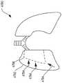
图1是根据本公开的至少一个方面的外科可视化系统100的示意图。外科可视化系统100可在解剖场内创建关键结构101的视觉表示。外科可视化系统100可用于例如临床分析和/或医疗干预。在某些情况下,外科可视化系统100可在术中使用,以在外科手术期间向临床医生提供关于接近度数据、尺寸和/或距离的实时或近实时的信息。外科可视化系统100被配置用于在术中识别关键结构和/或有利于外科装置避开关键结构101。例如,通过识别关键结构101,临床医生可避免在外科手术期间在关键结构101和/或关键结构101的预定接近度中的区域周围操纵外科装置。例如,临床医生可避免对例如被识别为关键结构101的静脉、动脉、神经和/或血管进行解剖和/或避免在这些关键结构附近进行解剖。在各种情况下,关键结构101可基于不同患者和/或不同手术来确定。1 is a schematic diagram of a
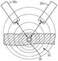
外科可视化系统100结合距离传感器系统104结合有组织识别和几何表面标测。结合起来,外科可视化系统100的这些特征可确定关键结构101在解剖场内的方位以及/或者外科装置102与可见组织的表面105和/或与关键结构101的接近度。此外,外科可视化系统100包括成像系统,该成像系统包括例如被配置成能够提供外科部位的实时视图的成像装置120,诸如相机。在各种情况下,成像装置120是光谱相机(例如,高光谱相机、多光谱相机或选择性光谱相机),该光谱相机被配置成能够检测反射的光谱波形并且基于对不同波长的分子响应来生成图像的光谱立方体。来自成像装置120的视图可被提供给临床医生,并且在本公开的各个方面,可基于组织识别、地形标测和距离传感器系统104用附加信息来增强这些视图。在此类情况下,外科可视化系统100包括多个子系统,即成像子系统、表面标测子系统、组织识别子系统和/或距离确定子系统。这些子系统可配合以在术中向临床医生提供高级数据合成和集成信息。The
成像装置可包括相机或成像传感器,该相机或成像传感器被配置成能够检测例如可见光、光谱光波(可见光或不可见光)和结构化光图案(可见光或不可见光)。在本公开的各个方面,成像系统可包括例如成像装置,诸如内窥镜。另外或另选地,成像系统可包括例如成像装置,诸如关节镜、血管镜、支气管镜、胆道镜、结肠镜、膀胱镜、十二指肠镜、肠镜、食管胃-十二指肠镜(胃镜)、喉镜、鼻咽-肾镜、乙状结肠镜、胸腔镜、输尿管镜或外镜。在其他情况下,诸如在开放外科手术应用中,成像系统可不包括观察镜。The imaging device may include a camera or imaging sensor configured to detect, for example, visible light, spectral light waves (visible or invisible), and structured light patterns (visible or invisible). In various aspects of the present disclosure, an imaging system may include, for example, an imaging device, such as an endoscope. Additionally or alternatively, an imaging system may include, for example, an imaging device such as an arthroscope, angioscope, bronchoscope, choledochoscope, colonoscope, cystoscope, duodenoscope, colonoscope, esophagogastro-duodenoscope (gastroscopy), laryngoscopy, nasopharyngoscopy, sigmoidoscopy, thoracoscopy, ureteroscopy or exooscopy. In other cases, such as in open surgical applications, the imaging system may not include a scope.
在本公开的各个方面,组织识别子系统可用光谱成像系统来实现。光谱成像系统可依赖于例如高光谱成像、多光谱成像或选择性光谱成像。组织的高光谱成像进一步在2016年3月1日公布的名称为“SYSTEM AND METHOD FOR GROSS ANATOMIC PATHOLOGY USINGHYPERSPECTRAL IMAGING”的美国专利号9,274,047中描述,该专利全文以引用方式并入本文。In various aspects of the present disclosure, the tissue identification subsystem may be implemented with a spectral imaging system. Spectral imaging systems may rely on, for example, hyperspectral imaging, multispectral imaging, or selective spectral imaging. Hyperspectral imaging of tissue is further described in US Patent No. 9,274,047, issued March 1, 2016, entitled "SYSTEM AND METHOD FOR GROSS ANATOMIC PATHOLOGY USINGHYPERSPECTRAL IMAGING," which is incorporated herein by reference in its entirety.
在本公开的各个方面,表面标测子系统可用光图案系统来实现,如本文进一步所述。光图案(或结构化光)用于表面标测是已知的。已知的表面标测技术可用于本文所述的外科可视化系统中。In various aspects of the present disclosure, the surface mapping subsystem may be implemented with a light patterning system, as described further herein. Light patterns (or structured light) are known for surface mapping. Known surface mapping techniques can be used in the surgical visualization system described herein.
结构化光是将已知图案(通常为网格或水平条)投射到表面上的过程。2017年3月2日公布的名称为“SET COMPRISING A SURGICAL INSTRUMENT”的美国专利申请公布2017/0055819以及2017年9月7日公布的名称为“DEPICTION SYSTEM”的美国专利申请公布2017/0251900公开了一种外科系统,该外科系统包括光源以及用于投射光图案的投射仪。2017年3月2日公布的名称为“SET COMPRISING A SURGICAL INSTRUMENT”的美国专利申请公布2017/0055819以及2017年9月7日公布的名称为“DEPICTION SYSTEM”的美国专利申请公布2017/0251900全文以引用方式并入本文。Structured light is the process of projecting a known pattern (usually a grid or horizontal strips) onto a surface. US Patent Application Publication 2017/0055819 entitled "SET COMPRISING A SURGICAL INSTRUMENT" published on March 2, 2017 and US Patent Application Publication 2017/0251900 entitled "DEPICTION SYSTEM" published on September 7, 2017 disclose A surgical system includes a light source and a projector for projecting a light pattern. The full text of US Patent Application Publication 2017/0055819 entitled "SET COMPRISING A SURGICAL INSTRUMENT" published on March 2, 2017 and US Patent Application Publication 2017/0251900 entitled "DEPICTION SYSTEM" published on September 7, 2017 Incorporated herein by reference.
在本公开的各个方面,距离确定系统可结合到表面标测系统中。例如,可利用结构化光来生成可见表面的三维虚拟模型并且确定相对于可见表面的各种距离。另外或另选地,距离确定系统可依赖于飞行时间测量来确定到外科部位处所识别的组织(或其他结构)的一个或多个距离。In various aspects of the present disclosure, the distance determination system may be incorporated into a surface mapping system. For example, structured light can be utilized to generate a three-dimensional virtual model of a visible surface and determine various distances relative to the visible surface. Additionally or alternatively, the distance determination system may rely on time-of-flight measurements to determine one or more distances to identified tissue (or other structures) at the surgical site.
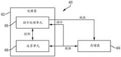
图2是可与外科可视化系统100一起使用的控制系统133的示意图。控制系统133包括与存储器134信号通信的控制电路132。存储器134存储可由控制电路132执行的指令,以确定和/或识别关键结构(例如,图1中的关键结构101),确定和/或计算一个或多个距离和/或三维数字表示,并将某些信息传送给一个或多个临床医生。例如,存储器134存储表面标测逻辑部件136、成像逻辑部件138、组织识别逻辑部件140或距离确定逻辑部件141或者逻辑部件136、138、140和141的任何组合。控制系统133还包括成像系统142,该成像系统具有一个或多个相机144(如图1中的成像装置120)、一个或多个显示器146或者一个或多个控件148或者这些元件的任何组合。相机144可包括一个或多个图像传感器135,以接收来自发射各种可见光谱和不可见光谱下的光的各种光源(例如,可见光、光谱成像器、三维透镜等)的信号。显示器146可包括一个或多个屏幕或监视器,用于向一个或多个临床医生描绘真实、虚拟和/或虚拟增强的图像和/或信息。FIG. 2 is a schematic diagram of a
在各个方面,相机144的心脏是图像传感器135。一般来讲,现代图像传感器135是包含高达数百万个离散光电探测器位点(称为像素)的固态电子装置。图像传感器135技术属于以下两类中的一类:电荷耦合器件(CCD)和互补金属氧化物半导体(CMOS)成像器,并且近来,短波红外(SWIR)是一种新兴的成像技术。另一种类型的图像传感器135采用混合CCD/CMOS架构(以名称“sCMOS”出售),并且由凸块粘结到CCD成像基板的CMOS读出集成电路(ROIC)组成。CCD和CMOS图像传感器135对大约350nm至1050nm的波长敏感,但该范围通常被给出为400nm至1000nm。一般来讲,CMOS传感器比CCD传感器对IR波长更敏感。固态图像传感器135基于光电效应,并且因此不能区分颜色。因此,存在两种类型的彩色CCD相机:单芯片和三芯片。单芯片彩色CCD相机提供常见的低成本成像解决方案,并且使用马赛克(例如,拜耳)光学滤光器将入射光分成一系列颜色,并且采用内插算法来解析全色图像。然后,每种颜色指向不同的像素集。三芯片彩色CCD相机通过采用棱镜将入射光谱的每个部分引导到不同的芯片来提供更高的分辨率。更准确的颜色再现是可能的,因为物体的空间中的每个点具有单独的RGB强度值,而不是使用算法来确定颜色。三芯片相机提供极高的分辨率。In various aspects, the heart of
控制系统133还包括光谱光源150和结构化光源152。在某些情况下,单个源可以是脉冲式的,以发射光谱光源150范围内的光的波长和结构化光源152范围内的光的波长。另选地,单个光源可以是脉冲式的,以提供不可见光谱中的光(例如红外光谱光)和可见光谱上的光的波长。光谱光源150可以是例如高光谱光源、多光谱光源和/或选择性光谱光源。在各种情况下,组织识别逻辑部件140可经由由相机144的图像传感器135部分接收的来自光谱光源150的数据来识别关键结构。表面标测逻辑部件136可基于反射的结构化光来确定可见组织的表面轮廓。利用飞行时间测量结果,距离确定逻辑部件141可确定到可见组织和/或关键结构101的一个或多个距离。来自表面标测逻辑部件136、组织识别逻辑部件140和距离确定逻辑部件141的一个或多个输出可被提供给成像逻辑部件138,并且可被组合、共混和/或重叠以经由成像系统142的显示器146传达给临床医生。The
说明书现在简要转到图2A至图2C,以描述用于控制外科可视化系统100的各个方面的控制电路132的各个方面。转到图2A,示出了根据本公开的至少一个方面的被配置成能够控制外科可视化系统100的各方面的控制电路400。控制电路400可被配置成能够实现本文所述的各种过程。控制电路400可以包括微控制器,该微控制器包括耦接到至少一个存储器电路404的一个或多个处理器402(例如,微处理器、微控制器)。存储器电路404存储机器可执行指令,这些机器可执行指令在由处理器402执行时使处理器402执行机器指令以实现本文所述的各种过程。处理器402可以是本领域中已知的多种单核或多核处理器中的任一种。存储器电路404可包括易失性存储介质和非易失性存储介质。处理器402可包括指令处理单元406和运算单元408。指令处理单元可被配置成能够从本公开的存储器电路404接收指令。The description now briefly turns to FIGS. 2A-2C to describe various aspects of the
图2B示出了根据本公开的至少一个方面的被配置成能够控制外科可视化系统100的各方面的组合逻辑电路410。组合逻辑电路410可被配置成能够实现本文所述的各种过程。组合逻辑电路410可包括有限状态机,该有限状态机包括组合逻辑部件412,该组合逻辑部件被配置成能够在输入414处接收与外科器械或工具相关联的数据,通过组合逻辑部件412处理数据并提供输出416。FIG. 2B illustrates
图2C示出了根据本公开的至少一个方面的被配置成能够控制外科可视化系统100的各方面的时序逻辑电路420。时序逻辑电路420或组合逻辑部件422可被配置成能够实现本文所述的各种过程。时序逻辑电路420可包括有限状态机。时序逻辑电路420可包括例如组合逻辑部件422、至少一个存储器电路424和时钟429。至少一个存储器电路424可存储有限状态机的当前状态。在某些情况下,时序逻辑电路420可以是同步的或异步的。组合逻辑部件422被配置成能够从输入426接收与外科装置或系统相关联的数据,通过组合逻辑部件422处理数据并提供输出428。在其他方面,电路可包括处理器(例如,图2A中的处理器402)和有限状态机的组合以实现本文的各种过程。在其他方面,有限状态机可包括组合逻辑电路(例如,组合逻辑电路410,图2B)和时序逻辑电路420的组合。FIG. 2C illustrates
再次参见图1中的外科可视化系统100,关键结构101可以是感兴趣的解剖结构。例如,关键结构101可以是输尿管、动脉诸如肠系膜上动脉、静脉诸如门静脉、神经诸如膈神经和/或肿瘤等解剖结构。在其他情况下,关键结构101可以是例如解剖场中的外来结构,诸如外科装置、外科紧固件、夹具、大头钉、探条、带和/或板。示例性关键结构在本文和前述同时提交的美国专利申请(包括例如于2018年9月11日提交的名称为“VISUALIZATION OFSURGICAL DEVICES”的美国专利申请号16/128,192)中进一步描述,这些专利申请全文以引用方式并入本文。Referring again to
在一个方面,关键结构101可嵌入组织103中。换句话说,关键结构101可定位在组织103的表面105下方。在此类情况下,组织103隐蔽关键结构101使其不被临床医生看见。从成像装置120的视角来看,关键结构101也被组织103遮蔽。组织103可以是例如脂肪、结缔组织、粘连和/或器官。在其他情况下,关键结构101可被部分地遮蔽使其不被看见。In one aspect,
图1还描绘了外科装置102。外科装置102包括端部执行器,该端部执行器具有从外科装置102的轴的远侧端部延伸的相对钳口。外科装置102可以是任何合适的外科装置,诸如例如解剖器、缝合器、抓紧器、施夹器和/或能量装置(包括单极探针、双极探针、消融探针和/或超声端部执行器)。另外或另选地,外科装置102可包括例如另一个成像或诊断模态,诸如超声装置。在本公开的一个方面,外科可视化系统100可被配置成能够实现识别一个或多个关键结构101以及外科装置102与关键结构101的接近度。FIG. 1 also depicts
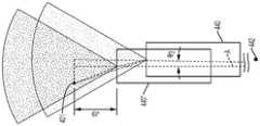
外科可视化系统100的成像装置120被配置成能够检测各种波长的光,诸如例如可见光、光谱光波(可见光或不可见光)和结构化光图案(可见光或不可见光)。成像装置120可包括用于检测不同信号的多个透镜、传感器和/或接收器。例如,成像装置120可以是高光谱、多光谱或选择性光谱相机,如本文进一步所述。成像装置120还可包括波形传感器122(诸如光谱图像传感器、检测器和/或三维相机透镜)。例如,成像装置120可包括一起使用以同时记录两个二维图像的右侧透镜和左侧透镜,并且因此生成外科部位的三维图像,渲染外科部位的三维图像,并且/或者确定外科部位处的一个或多个距离。另外或另选地,成像装置120可被配置成能够接收指示可见组织的形貌以及隐藏关键结构的识别和方位的图像,如本文进一步所述。例如,成像装置120的视场可与组织的表面105上的光(结构化光)的图案重叠,如图1所示。The
在一个方面,外科可视化系统100可结合到机器人系统110中。例如,机器人系统110可包括第一机器人臂112和第二机器人臂114。机器人臂112、114包括刚性结构构件116和接头118,这些接头可包括伺服马达控件。第一机器人臂112被配置成能够操纵外科装置102,并且第二机器人臂114被配置成能够操纵成像装置120。机器人控制单元可被配置成能够向机器人臂112、114发出控制运动,这些控制运动可影响例如外科装置102和成像装置120。In one aspect,
外科可视化系统100还包括发射器106,该发射器被配置成能够发射光的图案,诸如条纹、网格线和/或点,以使得能够确定表面105的形貌或地形。例如,投射光阵列130可用于表面105上的三维扫描和配准。投射光阵列130可从位于例如外科装置102和/或机器人臂112、114中的一者和/或成像装置120上的发射器106发射。在一个方面,投射光阵列130用于确定由组织103的表面105和/或表面105在术中的运动限定的形状。成像装置120被配置成能够检测从表面105反射的投射光阵列130,以确定表面105的形貌以及相对于表面105的各种距离。The
在一个方面,成像装置120还可包括光学波形发射器123,该光学波形发射器被配置成能够发射可穿透组织103的表面105并到达关键结构101的电磁辐射124(NIR光子)。成像装置120及其上的光学波形发射器123可能够由机器人臂114定位。成像装置120上的对应波形传感器122(例如,图像传感器、光谱仪或振动传感器)被配置成能够检测由波形传感器122接收的电磁辐射的影响。由光学波形发射器123发射的电磁辐射124的波长可被配置成能够使得能够识别解剖结构和/或物理结构(诸如关键结构101)的类型。关键结构101的识别可通过例如光谱分析、光声学和/或超声来实现。在一个方面,电磁辐射124的波长可以是可变的。波形传感器122和光学波形发射器123可包括例如多光谱成像系统和/或选择性光谱成像系统。在其他情况下,波形传感器122和光学波形发射器123可包括例如光声学成像系统。在其他情况下,光学波形发射器123可定位在与成像装置120分开的外科装置上。In one aspect,
外科可视化系统100还可包括距离传感器系统104,该距离传感器系统被配置成能够确定外科部位处的一个或多个距离。在一个方面,飞行时间距离传感器系统104可以是包括发射器(诸如发射器106)以及可定位在外科装置102上的接收器108的飞行时间距离传感器系统。在其他情况下,飞行时间发射器可与结构化光发射器分开。在一个一般方面,飞行时间距离传感器系统104的发射器106部分可包括非常微小的激光源,并且飞行时间距离传感器系统104的接收器108部分可包括匹配传感器。飞行时间距离传感器系统104可检测“飞行时间”或由发射器106发射的激光反弹回到接收器108的传感器部分所花费的时间。在发射器106中使用非常窄的光源使得距离传感器系统104能够确定到距离传感器系统104正前方的组织103的表面105的距离。仍然参见图1,de是从发射器106到组织103的表面105的发射器-组织距离,并且dt是从外科装置102的远侧端部到组织的表面105的装置-组织距离。距离传感器系统104可用于确定发射器-组织距离de。装置-组织距离dt可根据发射器106在外科装置102的轴上相对于外科装置102的远侧端部的已知方位获得。换句话讲,当发射器106与外科装置102的远侧端部之间的距离已知时,装置-组织距离dt可根据发射器-组织距离de确定。在某些情况下,外科装置102的轴可包括一个或多个关节运动接头,并且可能够相对于发射器106和钳口进行关节运动。关节运动构型可包括例如多接头椎骨状结构。在某些情况下,三维相机可用于对到表面105的一个或多个距离进行三角测量。The
在各种情况下,飞行时间距离传感器系统104的接收器108可安装在单独的外科装置上而不是外科装置102上。例如,接收器108可安装在插管或套管针上,外科装置102延伸穿过该插管或套管针以到达外科部位。在其他情况下,飞行时间距离传感器系统104的接收器108可安装在单独的机器人控制的臂(例如,机器人臂114)上,安装在由另一个机器人操作的可运动臂上和/或安装到手术室(OR)工作台或固定装置。在某些情况下,成像装置120包括飞行时间接收器108,以使用外科装置102上的发射器106与成像装置120之间的线来确定从发射器106到组织103的表面105的距离。例如,可基于飞行时间距离传感器系统104的发射器106(在外科装置102上)和接收器108(在成像装置120上)的已知方位来对距离de进行三角测量。接收器108的三维方位可以是已知的和/或在术中与机器人坐标平面配准。In various cases, receiver 108 of time-of-flight
在某些情况下,飞行时间距离传感器系统104的发射器106的方位可由第一机器人臂112控制,并且飞行时间距离传感器系统104的接收器108的方位可由第二机器人臂114控制。在其他情况下,外科可视化系统100可与机器人系统分开使用。在此类情况下,距离传感器系统104可独立于机器人系统。In some cases, the orientation of the
在某些情况下,机器人臂112、114中的一者或多者可与外科手术中使用的主机器人系统分开。机器人臂112、114中的至少一者可在没有伺服马达控件的情况下定位并与特定坐标系配准。例如,用于机器人臂110的闭环控制系统和/或多个传感器可控制和/或配准机器人臂112、114相对于特定坐标系的方位。类似地,外科装置102和成像装置120的方位可相对于特定坐标系配准。In some cases, one or more of the
仍然参见图1,dw是从位于成像装置120上的光学波形发射器123到关键结构101的表面的相机-关键结构距离,并且dA是关键结构101在组织103的表面105下方的深度(即,表面105的最靠近外科装置102的部分与关键结构101之间的距离)。在各个方面,从位于成像装置120上的光学波形发射器123发射的光学波形的飞行时间可被配置成能够确定相机-关键结构距离dw。光谱成像结合飞行时间传感器的使用在本文中进一步描述。此外,现在参见图3,在本公开的各个方面,关键结构101相对于组织103的表面105的深度dA可通过以下方法来确定:根据距离dw以及发射器106在外科装置102上和光学波形发射器123在成像装置120上的已知方位(以及因此它们之间的已知距离dx)进行三角测量,以确定距离dy(其为距离de和dA之和)。Still referring to FIG. 1,dw is the camera-critical structure distance from the
另外或另选地,来自光学波形发射器123的飞行时间可被配置成能够确定从光学波形发射器123到组织103的表面105的距离。例如,第一波形(或波形范围)可用于确定相机-关键结构距离dw,并且第二波形(或波形范围)可用于确定到组织103的表面105的距离。在此类情况下,不同波形可用于确定关键结构101在组织103的表面105下方的深度。Additionally or alternatively, the time of flight from the
另外或另选地,在某些情况下,距离dA可由超声、配准磁共振成像(MRI)或计算机断层摄影(CT)扫描来确定。在其他情况下,距离dA可用光谱成像来确定,因为由成像装置接收的检测信号可基于材料的类型而变化。例如,脂肪可以第一方式或第一量降低检测信号,并且胶原可以不同的第二方式或第二量降低检测信号。Additionally or alternatively, in some cases, distance dA may be determined by ultrasound,registered magnetic resonance imaging (MRI) or computed tomography (CT) scans. In other cases, the distance dA may be determined using spectral imaging, since the detection signal received by the imaging device may vary based on the type of material. For example, fat may reduce the detection signal in a first manner or amount, and collagen may reduce the detection signal in a second, different manner or amount.
现在参见图4中的外科可视化系统160,其中外科装置162包括光学波形发射器123以及被配置成能够检测反射的波形的波形传感器122。光学波形发射器123可被配置成能够发射波形,以用于确定与公共装置(诸如外科装置162)的距离dt和dw,如本文进一步所述。在此类情况下,从组织103的表面105到关键结构101的表面的距离dA可如下确定:Referring now to
dA=dw-dt。dA =dw -dt .
如本文所公开,关于可见组织、嵌入的关键结构和外科装置的各种信息可通过利用组合方法来确定,该组合方法结合被配置成能够检测光谱波长和结构化光阵列的图像传感器结合有一个或多个飞行时间距离传感器、光谱成像和/或结构化光阵列。此外,图像传感器可被配置成能够接收可见光,并且因此将外科部位的图像提供给成像系统。采用逻辑或算法来识别从飞行时间传感器接收的信息、光谱波长、结构化光和可见光,并且渲染表面组织和下面的解剖结构的三维图像。在各种情况下,成像装置120可包括多个图像传感器。As disclosed herein, various information about visible tissue, embedded critical structures, and surgical devices can be determined by utilizing a combined approach in conjunction with an image sensor configured to detect spectral wavelengths and a structured light array with a or multiple time-of-flight distance sensors, spectral imaging and/or structured light arrays. Additionally, the image sensor may be configured to receive visible light and thus provide an image of the surgical site to the imaging system. A logical OR algorithm is employed to identify the information received from the time-of-flight sensors, spectral wavelengths, structured and visible light, and render a three-dimensional image of the surface tissue and underlying anatomy. In various cases,
相机-关键结构距离dw也可以一种或多种替代方式进行检测。在一个方面,可利用例如荧光透视可视化技术(诸如荧光吲哚菁绿(ICG))来照亮关键结构201,如图6至图8所示。相机220可包括两个光学波形传感器222、224,这两个光学波形传感器同时拍摄关键结构201的左侧图像和右侧图像(图7A和图7B)。在此类情况下,相机220可描绘关键结构201在组织203的表面205下方的辉光,并且距离dw可由传感器222与224之间的已知距离来确定。在某些情况下,可通过利用多于一个相机或通过使相机在多个位置之间运动来更准确地确定距离。在某些方面,一个相机可由第一机器人臂控制,并且第二相机可由另一个机器人臂控制。在此类机器人系统中,一个相机可以是例如从动件臂上的从动件相机。从动件臂及其上的相机可被编程为跟踪另一个相机并保持例如特定的距离和/或透镜角度。The camera-critical structure distancedw can also be detected in one or more alternative ways. In one aspect,
在其他方面,外科可视化系统100可采用两个单独的波形接收器(即,相机/图像传感器)来确定dw。现在参见图9,如果关键结构301或其内容物(例如,血管或血管内容物)可诸如利用荧光透视发射信号302,则可根据已知位置处的两个单独的相机320a、320b对实际位置进行三角测量。In other aspects, the
在另一方面,现在参见图10A和图10B,外科可视化系统可采用抖动或移动相机440来确定距离dw。相机440是机器人控制的,使得相机440在不同方位处的三维坐标是已知的。在各种情况下,相机440可在插管或患者接口处枢转。例如,如果关键结构401或其内容物(例如,血管或血管内容物)可诸如利用荧光透视发射信号,则可根据在两个或更多个已知位置之间快速运动的相机440对实际位置进行三角测量。在图10A中,相机440沿轴线A轴向移动。更具体地,相机440沿轴线A更靠近关键结构401平移距离d1,以平移到被指示为位置440'的位置,诸如通过在机器人臂上移入和移出。当相机440运动距离d1并且视图的尺寸相对于关键结构401改变时,可计算到关键结构401的距离。例如,4.28mm的轴向平移(距离d1)可对应于6.28度的角度θ1和8.19度的角度θ2。另外或另选地,相机440可沿不同方位之间的弧线旋转或扫掠。现在参见图10B,相机440沿轴线A轴向移动并且围绕轴线A旋转角度θ3。用于相机440的旋转的枢转点442定位在插管/患者接口处。在图10B中,相机440平移并旋转到位置440”。当使相机440运动并且视图边缘关于关键结构401改变时,可计算到关键结构401的距离。在图10B中,距离d2可为例如9.01mm,并且角度θ3可为例如0.9度。In another aspect, referring now to Figures 10A and 10B, the surgical visualization system may employ shaking or moving
图5描绘了外科可视化系统500,其在许多方面类似于外科可视化系统100。在各种情况下,外科可视化系统500可以是外科可视化系统100的另一个范例。类似于外科可视化系统100,外科可视化系统500包括外科装置502和成像装置520。成像装置520包括光谱光发射器523,该光谱光发射器被配置成能够发射多个波长的光谱光,以获得例如隐藏结构的光谱图像。在各种情况下,成像装置520还可包括三维相机和相关联的电子处理电路。外科可视化系统500被示出为在术中用于识别和有利于避开在表面上不可见的某些关键结构,诸如器官503(在该示例中为子宫)中的输尿管501a和血管501b。FIG. 5 depicts a
外科可视化系统500被配置成能够经由结构化光确定从外科装置502上的发射器506到子宫503的表面505的发射器-组织距离de。外科可视化系统500被配置成能够基于发射器-组织距离de来外推从外科装置502到子宫503的表面505的装置-组织距离dt。外科可视化系统500还被配置成能够确定从输尿管501a到表面505的组织-输尿管距离dA以及从成像装置520到输尿管501a的相机-输尿管距离dw。如本文关于图1所述,例如,外科可视化系统500可利用例如光谱成像和飞行时间传感器来确定距离dw。在各种情况下,外科可视化系统500可基于本文所述的其他距离和/或表面标测逻辑部件来确定(例如,三角测量)组织-输尿管距离dA(或深度)。
现在参见图11,其中描绘了用于例如外科可视化系统(诸如外科可视化系统100)的控制系统600的示意图。例如,控制系统600是转换系统,该转换系统整合光谱特征组织识别和结构化光组织定位以识别关键结构,特别是当这些结构被其他组织(诸如脂肪、结缔组织、血液和/或其他器官)遮蔽时。此类技术也可用于检测组织可变性,诸如区分器官内的肿瘤和/或不健康组织与健康组织。Referring now to FIG. 11 , depicted therein is a schematic diagram of a
控制系统600被配置用于实现高光谱成像和可视化系统,其中利用分子响应来检测和识别外科视场中的解剖结构。控制系统600包括转换逻辑电路648以将组织数据转换成外科医生可用的信息。例如,可利用基于相对于遮蔽材料的波长的可变反射率来识别解剖结构中的关键结构。此外,控制系统600将所识别的光谱特征和结构光数据组合在图像中。例如,控制系统600可用于创建三维数据集,以在具有增强图像叠加的系统中用于外科用途。可在术中和术前两者使用附加视觉信息来使用技术。在各种情况下,控制系统600被配置成能够在接近一个或多个关键结构时向临床医生提供警告。可采用各种算法来基于外科手术和与关键结构的接近度引导机器人自动化和半自动化方法。
采用投射光阵列在术中确定组织形状和运动。另选地,闪光激光雷达可用于组织的表面标测。Tissue shape and motion are determined intraoperatively using a projected light array. Alternatively, flash lidar can be used for surface mapping of tissue.
控制系统600被配置成能够检测关键结构并提供关键结构的图像叠加,并且测量到可见组织的表面的距离和到嵌入/掩埋关键结构的距离。在其他情况下,控制系统600可测量到可见组织的表面的距离或检测关键结构,并且提供关键结构的图像叠加。
控制系统600包括光谱控制电路602。例如,光谱控制电路602可以是现场可编程门阵列(FPGA)或如本文结合图2A至图2C所述的另一种合适的电路配置。光谱控制电路602包括处理器604以从视频输入处理器606接收视频输入信号。例如,处理器604可被配置用于高光谱处理并且可利用C/C++代码。例如,视频输入处理器606接收控制(元数据)数据的视频输入,诸如快门时间、波长和传感器分析。处理器604被配置成能够处理来自视频输入处理器606的视频输入信号并将视频输出信号提供给视频输出处理器608,该视频输出处理器包括例如接口控制(元数据)数据的高光谱视频输出。视频输出处理器608将视频输出信号提供给图像叠加控制器610。
视频输入处理器606经由患者隔离电路614联接到患者侧处的相机612。如前所述,相机612包括固态图像传感器634。患者隔离电路可包括多个变压器,使得患者与系统中的其他电路隔离。相机612通过光学器件632和图像传感器634接收术中图像。图像传感器634可包括例如CMOS图像传感器,或者可包括例如本文结合图2所述的任何图像传感器技术。在一个方面,相机612以14位/像素信号输出图像。应当理解,在不脱离本公开的范围的情况下,可采用更高或更低的像素分辨率。隔离的相机输出信号613被提供给彩色RGB融合电路616,该融合电路利用硬件寄存器618和Nios2协处理器620来处理相机输出信号613。彩色RGB融合输出信号被提供给视频输入处理器606和激光脉冲控制电路622。
激光脉冲控制电路622控制激光引擎624。激光引擎624输出包括近红外(NIR)在内的多个波长(λ1,λ2,λ3......λn)的光。激光引擎624可在多种模式下操作。在一个方面,激光引擎624可在例如两种模式下操作。在第一模式(例如正常操作模式)下,激光引擎624输出照明信号。在第二模式(例如,识别模式)下,激光引擎624输出RGBG和NIR光。在各种情况下,激光引擎624可在偏振模式下操作。The laser
来自激光引擎624的光输出626照亮术中外科部位627中的目标解剖结构。激光脉冲控制电路622还控制用于激光图案投射仪630的激光脉冲控制器628,该激光图案投射仪将预先确定的波长(λ2)的激光图案631(诸如线和/或点的网格或图案)投射在外科部位627处的手术组织或器官上。相机612接收图案化光以及通过相机光学器件632输出的反射光。图像传感器634将所接收的光转换成数字信号。The
彩色RGB融合电路616还将信号输出到图像叠加控制器610和视频输入模块636,以用于读取由激光图案投射仪630投射到外科部位627处的目标解剖结构上的激光图案631。处理模块638处理激光图案631并且输出表示到外科部位627处的可见组织的距离的第一视频输出信号640。数据被提供给图像叠加控制器610。处理模块638还输出表示外科部位处的目标解剖结构的组织或器官的三维渲染形状的第二视频信号642。Color
第一视频输出信号640和第二视频输出信号642包括表示关键结构在三维表面模型上的方位的数据,该数据被提供给整合模块643。结合来自光谱控制电路602的视频输出处理器608的数据,整合模块643可确定到掩埋关键结构的距离dA(图1)(例如,经由三角测量算法644),并且距离dA可经由视频输出处理器646提供给图像叠加控制器610。上述转换逻辑部件可涵盖转换逻辑电路648、中间视频监视器652以及定位在外科部位627处的相机624/激光图案投射仪630。First
在各种情况下,可采用来自CT或MRI扫描的术前数据650来配准或匹配某些三维可变形组织。此类术前数据650可被提供给整合模块643并最终提供给图像叠加控制器610,使得此类信息可与来自相机612的视图叠加并被提供给视频监视器652。术前数据的配准在本文和前述同时提交的美国专利申请(包括例如于2018年9月11日提交的名称为为“INTEGRATION OF IMAGING DATA”的美国专利申请号16/128,195)中进一步描述,这些专利申请全文以引用方式并入本文。In various cases,
视频监视器652可从图像叠加控制器610输出整合/增强视图。临床医生可在一个或多个监视器上在不同视图之间选择和/或切换。在第一监视器652a上,临床医生可在(A)其中描绘可见组织的三维渲染的视图与(B)其中在可见组织的三维渲染上描绘一个或多个隐藏关键结构的增强视图之间切换。在第二监视器652b上,临床医生可例如将距离测量切换到一个或多个隐藏关键结构和/或可见组织的表面。Video monitor 652 may output the integrated/enhanced view from
控制系统600和/或其各种控制电路可结合到本文所公开的各种外科可视化系统中。
图12示出了根据本公开的至少一个方面的结构化(或图案化)光系统700。如本文所述,条纹或线形式的结构化光例如可从光源和/或投射仪706被投射到目标解剖结构的表面705上,以识别表面705的形状和轮廓。在各个方面可类似于成像装置120(图1)的相机720例如可被配置成能够检测光在表面705上的投射图案。投射图案在撞击表面705时变形的方式允许视觉系统计算目标解剖结构的深度和表面信息。12 illustrates a structured (or patterned)
在某些情况下,可利用不可见的(或察觉不到的)结构化光,其中在不干扰投射图案可能混淆的其他计算机视觉任务的情况下使用该结构化光。例如,可利用在两个完全相反的图案之间交替的红外光或极快的可见光帧速率来防止干扰。结构化光在en.wikipedia.org/wiki/Structured_light处进一步描述。In some cases, invisible (or imperceptible) structured light may be utilized, where the structured light is used without interfering with other computer vision tasks where the projected pattern may confound. For example, interference can be prevented with infrared light or an extremely fast visible light frame rate alternating between two diametrically opposed patterns. Structured light is further described at en.wikipedia.org/wiki/Structured_light.
如上所述,本文描述的各种外科可视化系统可以用于将各种不同类型的组织和/或解剖结构可视化,包括可被光谱的可见部分中的EMR遮挡而无法可视化的组织和/或解剖结构。在一个方面,外科可视化系统可以利用光谱成像系统来基于组成材料的不同组合来对不同类型的组织进行可视化。特别地,光谱成像系统可以被配置成能够基于组织在各种EMR波长上的吸收系数来检测被可视化的组织内各种组成材料的存在。光谱成像系统可以进一步被配置成能够基于组成材料的特定组合来表征被可视化的组织的组织类型。为了说明,图13A是描绘各种生物材料的吸收系数如何在EMR波长光谱上变化的曲线图2300。在曲线图2300中,纵轴2303表示生物材料的吸收系数(例如,以cm-1为单位),横轴2304表示EMR波长(例如,以μm为单位)。曲线图2300进一步示出了表示水在各种EMR波长下的吸收系数的第一条线2310、表示蛋白质在各种EMR波长下的吸收系数的第二条线2312、表示黑色素在各种EMR波长下的吸收系数的第三条线2314、表示脱氧血红蛋白在各种EMR波长下的吸收系数的第四条线2316、表示氧合血红蛋白在各种EMR波长下的吸收系数的第五条线2318,以及表示胶原蛋白在各种EMR波长下的吸收系数的第六条线2319。不同的组织类型具有组成材料的不同组合,因此由外科可视化系统可视化的组织类型可以根据检测到的组成材料的特定组合来识别和区分。因此,光谱成像系统可以被配置成能够发射多个不同波长的EMR,基于在不同波长处检测到的吸收EMR吸收响应来确定组织的组成材料,然后基于组成材料的特定检测组合来表征组织类型。As noted above, the various surgical visualization systems described herein can be used to visualize a variety of different types of tissue and/or anatomy, including tissue and/or anatomy that may be obscured from visualization by EMR in the visible portion of the spectrum . In one aspect, a surgical visualization system can utilize a spectral imaging system to visualize different types of tissue based on different combinations of constituent materials. In particular, the spectral imaging system can be configured to be able to detect the presence of various constituent materials within the visualized tissue based on the absorption coefficients of the tissue at various EMR wavelengths. The spectral imaging system can be further configured to be able to characterize the tissue type of the tissue being visualized based on the particular combination of constituent materials. To illustrate, FIG. 13A is a graph 2300 depicting how the absorption coefficients of various biomaterials vary over the EMR wavelength spectrum. In the graph 2300, the vertical axis 2303 represents the absorption coefficient of the biological material (eg, in cm−1 ), and the
图13B示出了利用光谱成像技术来对不同的组织类型和/或解剖结构进行可视化。在图13B中,光谱发射器2320(例如,光谱光源150)被成像系统用来对外科部位2325进行可视化。由光谱发射器2320发射并从外科部位2325处的组织和/或结构反射的EMR可以由图像传感器135(图2)接收,以对组织和/或结构进行可视化;该组织和/或结构可以是可见的(例如,位于外科部位2325的表面)或被遮挡的(例如,位于外科部位2325处的其他组织和/或结构的下面)。在该示例中,成像系统142(图2)可以基于光谱特征来对肿瘤2332、动脉2334和各种异常2338(即,与已知或预期的光谱特征不相符的组织)进行可视化,所述光谱特征由不同组织/结构类型中每一个的组成材料的不同吸收特性(例如,吸收系数)来表征。可视化的组织和结构可以显示在与成像系统142关联或联接的显示屏上,例如成像系统显示器146(图2)、主显示器2119(图18)、非无菌显示器2109(图18)、集线器显示器2215(图19)、装置/器械显示器2237(图19)等。Figure 13B illustrates the use of spectral imaging techniques to visualize different tissue types and/or anatomical structures. In FIG. 13B, spectral emitter 2320 (eg, spectral light source 150) is used by the imaging system to visualize
此外,成像系统142可以被配置成能够根据所识别的组织和/或结构类型来定制或更新所显示的外科部位可视化。例如,成像系统142可以在显示屏(例如,显示器146)上显示与正在可视化的肿瘤2332相关联的边缘2330a。边缘2330a可以指示应该切除以确保肿瘤2332完全切除的组织的面积或数量。控制系统133(图2)可以被配置成能够基于由成像系统142识别的组织和/或结构来控制或更新边缘2330a的尺寸。在所示示例中,成像系统142已经识别了FOV内的多个异常2338。因此,控制系统133可以将显示的边缘2330a调整到第一更新边缘2330b,该第一更新边缘2330b具有足够的尺寸来涵盖异常2338。此外,成像系统142还识别出了与最初显示的边缘2330a部分重叠的动脉2334(如动脉2334的高亮区域2336所示)。因此,控制系统133可以将显示的边缘2330a调整到第二更新边缘2330c,该第二更新边缘具有足够的尺寸来涵盖动脉2334的相关部分。Additionally, the
除了以上关于图13A和13B所描述的吸收特性之外或代替所述吸收特性,还可以根据组织和/或结构的反射特性在EMR波长光谱上对其进行成像或表征。例如,图13C-13E示出了不同类型的组织或结构在不同EMR波长上的反射率的各种曲线图。图13C是例示性输尿管特征相对于遮蔽物的图形表示1050。图13D是例示性动脉特征相对于遮蔽物的图形表示1052。图13E是例示性神经特征相对于遮蔽物的图形表示1054。图13C-13E中的曲线表示特定结构(输尿管、动脉和神经)相对于脂肪、肺组织和血液在相应波长的相应反射率的反射率与波长(nm)的函数关系。这些曲线图仅仅是出于说明性目的,并且应当理解,其他组织和/或结构可以具有相应的可检测反射特征,该反射特征将允许对组织和/或结构进行识别和可视化。In addition to or in lieu of the absorption properties described above with respect to Figures 13A and 13B, tissue and/or structures can also be imaged or characterized over the EMR wavelength spectrum based on their reflection properties. For example, Figures 13C-13E show various plots of reflectivity for different types of tissues or structures at different EMR wavelengths. Figure 13C is a
在各种情况下,可基于外科部位处的预期关键结构和/或遮蔽物来识别和利用用于光谱成像的选定波长(即,“选择性光谱”成像)。通过利用选择性光谱成像,可最小化获得光谱图像所需的时间量,使得可实时或接近实时地获得信息,并在手术中加以利用。在各种情况下,波长可由临床医生选择或由控制电路基于临床医生的输入来选择。在某些情况下,波长可基于例如机器学习和/或控制电路可经由云访问的大数据来选择。In various cases, selected wavelengths for spectral imaging (ie, "selective spectral" imaging) may be identified and utilized based on expected critical structures and/or occlusions at the surgical site. By utilizing selective spectral imaging, the amount of time required to obtain a spectral image can be minimized so that information can be obtained in real-time or near real-time and utilized in surgery. In various cases, the wavelength may be selected by the clinician or by the control circuit based on the clinician's input. In some cases, wavelengths may be selected based on, for example, machine learning and/or big data accessible to control circuitry via the cloud.
光谱成像到组织的前述应用可在手术中用于测量波形发射器与被组织遮蔽的关键结构之间的距离。在本公开的一个方面,现在参见图14和图15,示出了利用波形1124、1125的飞行时间传感器系统1104。在某些情况下,飞行时间传感器系统1104可结合到外科可视化系统100(图1)中。飞行时间传感器系统1104包括相同外科装置1102上的波形发射器1106和波形接收器1108。发射波1124从发射器1106延伸到关键结构1101,并且接收波1125被接收器1108从关键结构1101反射回去。外科装置1102穿过延伸到患者的腔1107中的套管针1110定位。The aforementioned application of spectral imaging to tissue can be used in surgery to measure the distance between a waveform emitter and critical structures obscured by tissue. In one aspect of the present disclosure, referring now to FIGS. 14 and 15 , a time-of-
波形1124、1125被配置成能够穿透遮蔽组织1103。例如,波形1124、1125的波长可在NIR或SWIR波长光谱中。在一个方面,光谱信号(例如,高光谱、多光谱或选择性光谱)或光声学信号可从发射器1106发射并且可穿透其中隐蔽有关键结构1101的组织1103。所发射的波形1124可被关键结构1101反射。所接收的波形1125可由于外科装置1102的远侧端部与关键结构1101之间的距离d而被延迟。在各种情况下,可基于关键结构1101的光谱特征来选择波形1124、1125以靶向组织1103内的关键结构1101,如本文进一步所述。在各种情况下,发射器1106被配置成能够提供二进制信号开和关,如图15所示,例如该二进制信号可由接收器1108测量。Waveforms 1124 , 1125 are configured to penetrate masking
基于发射波1124与接收波1125之间的延迟,飞行时间传感器系统1104被配置成能够确定距离d(图14)。图14的发射器1106和接收器1108的飞行时间时序图1130在图15中示出。延迟是距离d的函数,并且距离d由下式给出:Based on the delay between the transmitted

其中:in:
c=光的速度;c = speed of light;
t=脉冲的长度;t = length of pulse;
q11=发射光时累积的电荷;以及q11 = charge accumulated when light is emitted; and
q2=不发射光时累积的电荷。q2 = charge accumulated when no light is emitted.
如本文所提供,波形1124、1125的飞行时间对应于图14中的距离d。在各种情况下,附加发射器/接收器和/或来自发射器1106的脉冲信号可被配置成能够发射非穿透信号。非穿透组织可被配置成能够确定从发射器到遮蔽组织1103的表面1105的距离。在各种情况下,关键结构1101的深度可由下式确定:As provided herein, the time of flight of the
dA=dw-dt。dA =dw -dt .
其中:in:
dA=关键结构1101的深度;dA = depth of
dw=从发射器1106到关键结构1101的距离(图14中的d);以及dw = distance from
dt=从发射器1106(在外科装置1102的远侧端部上)到遮蔽组织1103的表面1105的距离。dt = distance from the transmitter 1106 (on the distal end of the surgical device 1102 ) to the
在本公开的一个方面,现在参见图16,示出了利用波1224a、1224b、1224c、1225a、1225b、1225c的飞行时间传感器系统1204。在某些情况下,飞行时间传感器系统1204可结合到外科可视化系统100(图1)中。飞行时间传感器系统1204包括波形发射器1206和波形接收器1208。波形发射器1206定位在第一外科装置1202a上,并且波形接收器1208定位在第二外科装置1202b上。外科装置1202a、1202b分别穿过其相应的套管针1210a、1210b定位,这两个套管针延伸到患者的腔1207中。发射波1224a、1224b、1224c从发射器1206朝向外科部位延伸,并且接收波1225a、1225b、1225c从外科部位处的各种结构和/或表面反射回接收器1208。In one aspect of the present disclosure, referring now to FIG. 16, a time-of-
不同的发射波1224a、1224b、1224c被配置成能够靶向外科部位处的不同类型的材料。例如,波1224a靶向遮蔽组织1203,波1224b靶向第一关键结构1201a(例如,血管),并且波1224c靶向第二关键结构1201b(例如,癌性肿瘤)。波1224a、1224b、1224c的波长可在可见光、NIR或SWIR波长光谱中。例如,可见光可从组织1203的表面1205反射,并且NIR和/或SWIR波形可被配置成能够穿透组织1203的表面1205。在各个方面,如本文所述,光谱信号(例如,高光谱、多光谱或选择性光谱)或光声学信号可从发射器1206发射。在各种情况下,可基于关键结构1201a、1201b的光谱特征来选择波1224b、1224c以靶向组织1203内的关键结构1201a、1201b,如本文进一步所述。光声学成像在各种美国专利申请中进一步描述,这些专利申请以引用方式并入本公开中。The different transmitted
发射波1224a、1224b、1224c可从目标材料(即,分别为表面1205、第一关键结构1201a和第二结构1201b)反射。所接收的波形1225a、1225b、1225c可由于图16所示的距离d1a、d2a、d3a、d1b、d2b、d2c而被延迟。The emitted
在其中发射器1206和接收器1208可独立定位(例如,定位在单独的外科装置1202a、1202b上和/或由单独的机器人臂控制)的飞行时间传感器系统1204中,可根据发射器1206和接收器1208的已知方位计算各种距离d1a、d2a、d3a、d1b、d2b、d2c。例如,当外科装置1202a、1202b由机器人控制时,这些方位可以是已知的。了解发射器1206和接收器1208的位置以及光子流靶向某一组织的时间和由接收器1208接收的该特定响应的信息可允许确定距离d1a、d2a、d3a、d1b、d2b、d2c。在一个方面,可使用穿透波长对到被遮蔽的关键结构1201a、1201b的距离进行三角测量。由于光的速度对于任何波长的可见光或不可见光是恒定的,因此飞行时间传感器系统1204可确定各种距离。In a time-of-
仍然参见图16,在各种情况下,在提供给临床医生的视图中,接收器1208可被旋转成使得所得图像中的目标结构的质心保持恒定,即在垂直于所选目标结构1203、1201a或1201b的轴线的平面中。此类取向可快速传送关于关键结构的一个或多个相关距离和/或视角。例如,如图16所示,从关键结构1201a垂直于视平面(即,血管在页面内/页面外取向)的视角显示外科部位。在各种情况下,此类取向可以是默认设置;然而,该视图可由临床医生旋转或以其他方式调整。在某些情况下,临床医生可在限定由成像系统提供的外科部位的视角的不同表面和/或目标结构之间切换。Still referring to Fig. 16, in various cases, in the view provided to the clinician, the
在各种情况下,接收器1208可安装在套管针或插管(诸如套管针1210b)上,例如外科装置1202b通过该套管针或插管定位。在其他情况下,接收器1208可安装在三维方位已知的单独机器人臂上。在各种情况下,接收器1208可安装在与控制外科装置1202a的机器人分开的可运动臂上,或者可安装到可在术中与机器人坐标平面配准的手术室(OR)工作台。在此类情况下,发射器1206和接收器1208的方位可能够与同一坐标平面配准,使得可根据来自飞行时间传感器系统1204的输出对距离进行三角测量。In various instances,
将飞行时间传感器系统和近红外光谱(NIRS)(称为TOF-NIRS,其能够测量具有纳秒分辨率的NIR光的时间分辨特征图)组合可见于名称为“TIME-OF-FLIGHT NEAR-INFRAREDSPECTROSCOPY FOR NONDESTRUCTIVE MEASUREMENT OF INTERNAL QUALITY INGRAPEFRUIT”(美国园艺科学学会杂志(Journal of the American Society forHorticultural Science),2013年5月,第138卷,第3期,第225-228页)的文章(该文章全文以引用方式并入本文)中,并且可在journal.ashspublications.org/content/138/3/225.full处获取。Combining a time-of-flight sensor system and near-infrared spectroscopy (NIRS), known as TOF-NIRS, which is capable of measuring time-resolved feature maps of NIR light with nanosecond resolution, can be seen in the title "TIME-OF-FLIGHT NEAR-INFRAREDSPECTROSCOPY" FOR NONDESTRUCTIVE MEASUREMENT OF INTERNAL QUALITY INGRAPEFRUIT" (Journal of the American Society for Horticultural Science, May 2013, Vol. 138, No. 3, pp. 225-228) incorporated herein by reference) and available at journal.ashspublications.org/content/138/3/225.full.
在各种情况下,飞行时间光谱波形被配置成能够确定关键结构的深度和/或外科装置与关键结构的接近度。此外,本文所公开的各种外科可视化系统包括表面标测逻辑部件,该表面标测逻辑部件被配置成能够创建可见组织的表面的三维渲染。在此类情况下,即使当可见组织阻挡关键结构时,临床医生也可知道外科装置与关键结构的接近度(或缺乏接近度)。在一种情况下,外科部位的形貌由表面标测逻辑部件提供在监视器上。如果关键结构靠近组织的表面,则光谱成像可将关键结构的方位传达给临床医生。例如,光谱成像可检测表面的5mm或10mm内的结构。在其他情况下,光谱成像可检测组织的表面下方10mm或20mm的结构。基于光谱成像系统的已知限值,系统被配置成能够在光谱成像系统根本无法检测到关键结构的情况下传达该关键结构在范围外。因此,临床医生可继续移动外科装置和/或操纵组织。当关键结构移动到光谱成像系统范围内时,系统可识别该结构,并且因此传送该结构在范围内。在此类情况下,当初始识别结构和/或在预定义的接近度区域内进一步移动结构时,可提供警示。在此类情况下,即使光谱成像系统利用已知边界/范围未识别关键结构,也可向临床医生提供接近度信息(即,缺乏接近度)。In various cases, the time-of-flight spectral waveform is configured to be able to determine the depth of the critical structure and/or the proximity of the surgical device to the critical structure. Additionally, various surgical visualization systems disclosed herein include surface mapping logic configured to create a three-dimensional rendering of the surface of visible tissue. In such cases, the clinician may know the proximity (or lack of proximity) of the surgical device to the critical structure, even when visible tissue blocks the critical structure. In one case, the topography of the surgical site is provided on the monitor by the surface mapping logic. Spectral imaging can communicate the location of critical structures to clinicians if they are close to the surface of the tissue. For example, spectral imaging can detect structures within 5mm or 10mm of a surface. In other cases, spectral imaging can detect structures 10mm or 20mm below the surface of the tissue. Based on the known limits of the spectral imaging system, the system is configured to be able to communicate that a critical structure is out of range if the spectral imaging system cannot detect the critical structure at all. Thus, the clinician can continue to move the surgical device and/or manipulate the tissue. When a critical structure moves into range of the spectral imaging system, the system can identify the structure and therefore transmit the structure within range. In such cases, an alert may be provided when the structure is initially identified and/or moved further within a predefined proximity area. In such cases, proximity information (ie, lack of proximity) may be provided to the clinician even if the spectral imaging system does not identify critical structures with known boundaries/ranges.
本文所公开的各种外科可视化系统可被配置成能够在手术中识别关键结构的存在和/或关键结构的接近度,并且在通过意外解剖和/或横切损坏关键结构之前警示临床医生。在各个方面,外科可视化系统被配置成能够识别例如以下关键结构中的一种或多种关键结构:输尿管、肠、直肠、神经(包括膈神经、喉返神经[RLN]、骶岬面部神经、迷走神经以及它们的分支)、血管(包括肺动脉和大叶动脉以及肺静脉和大叶静脉、肠系膜下动脉[IMA]及其分支、直肠上动脉、乙状动脉和左结肠动脉)、肠系膜上动脉(SMA)及其分支(包括中结肠动脉、右结肠动脉、回肠动脉)、肝动脉及其分支、门静脉及其分支、脾动脉/静脉及其分支、外部和内部(下腹部)回肠血管、短胃动脉、子宫动脉、骶中血管和淋巴结。此外,外科可视化系统被配置成能够指示外科装置与关键结构的接近度和/或在外科装置靠近关键结构时警告临床医生。The various surgical visualization systems disclosed herein can be configured to be able to identify the presence and/or proximity of critical structures during surgery and alert the clinician prior to damage to critical structures through accidental dissection and/or transection. In various aspects, the surgical visualization system is configured to identify, for example, one or more of the following key structures: ureter, bowel, rectum, nerves (including phrenic nerve, recurrent laryngeal nerve [RLN], sacral promontory facial nerve, vagus nerve and their branches), blood vessels (including pulmonary and lobar arteries and pulmonary and lobar veins, inferior mesenteric artery [IMA] and its branches, superior rectal artery, sigmoid artery, and left colic artery), superior mesenteric artery (SMA) ) and its branches (including midcolic artery, right colic artery, ileal artery), hepatic artery and its branches, portal vein and its branches, splenic artery/vein and its branches, external and internal (lower abdominal) ileal vessels, short gastric artery , uterine artery, middle sacral vessels and lymph nodes. Additionally, the surgical visualization system is configured to be able to indicate the proximity of the surgical device to critical structures and/or to alert the clinician when the surgical device is in proximity to critical structures.
本公开的各个方面提供了手术中关键结构识别(例如,输尿管、神经和/或血管的识别)和器械接近度监视。例如,本文所公开的各种外科可视化系统可包括光谱成像和外科器械跟踪,这使得能够可视化例如组织的表面下方(诸如组织的表面下方1.0cm至1.5cm)的关键结构。在其他情况下,外科可视化系统可识别组织的表面下方小于1.0cm或大于1.5cm的结构。例如,如果结构由于深度原本不能被看到,则即使例如可识别仅在表面0.2mm内的结构的外科可视化系统也可以是有价值的。在各个方面,外科可视化系统可例如利用关键结构的虚拟描绘作为叠加在可见组织的表面上的可见白光图像来增强临床医生的视图。外科可视化系统可提供外科器械的远侧末端的实时三维空间跟踪,并且可例如在外科器械的远侧末端在关键结构的特定范围内(诸如在关键结构的1.0cm内)移动时提供接近度警示。Various aspects of the present disclosure provide for intraoperative key structure identification (eg, identification of ureters, nerves, and/or blood vessels) and instrument proximity monitoring. For example, various surgical visualization systems disclosed herein may include spectral imaging and surgical instrument tracking, which enable visualization of, for example, critical structures below the surface of tissue, such as 1.0 cm to 1.5 cm below the surface of tissue. In other cases, the surgical visualization system may identify structures that are less than 1.0 cm or greater than 1.5 cm below the surface of the tissue. For example, even a surgical visualization system that can identify structures only within 0.2 mm of the surface may be valuable if the structures would otherwise not be visible due to depth. In various aspects, a surgical visualization system may enhance a clinician's view, eg, with virtual depictions of key structures as visible white light images superimposed on the surface of visible tissue. The surgical visualization system can provide real-time three-dimensional spatial tracking of the distal tip of a surgical instrument, and can provide proximity alerts, for example, when the distal tip of a surgical instrument is moved within a specific range of a critical structure, such as within 1.0 cm of a critical structure .
本文所公开的各种外科可视化系统可识别解剖何时太靠近关键结构。基于温度(即,在可能有损坏/加热/熔融关键结构的风险的关键结构附近太热)和/或基于张力(即,在可能有损坏/撕裂/牵拉关键结构的风险的关键结构附近张力太大),解剖可能“太靠近”关键结构。例如,当在结扎之前使血管骨架化时,此类外科可视化系统可有利于在血管周围进行解剖。在各种情况下,可利用热成像相机来读取外科部位处的热量并向临床医生提供基于所检测到的热量和从工具到结构的距离的警告。例如,如果工具的温度高于预定义阈值(诸如例如120℉),则可在第一距离(诸如例如10mm)处向临床医生提供警示,并且如果工具的温度小于或等于预定义阈值,则可在第二距离(诸如例如5mm)处向临床医生提供警示。预定义阈值和/或警告距离可以是默认设置和/或可临床医生编程。另外或另选地,接近度警示可与由工具本身(诸如测量例如单极或双极解剖器或血管密封器的远侧钳口中的热量的热电偶)进行的热测量关联。Various surgical visualization systems disclosed herein can identify when anatomy is too close to critical structures. Temperature-based (ie, too hot near critical structures that may risk damaging/heating/melting critical structures) and/or tension-based (ie, near critical structures that may risk damaging/tearing/pulling critical structures too much tension), the dissection may be "too close" to critical structures. Such surgical visualization systems may facilitate dissection around the vessel, for example, when the vessel is skeletonized prior to ligation. In various cases, thermal imaging cameras can be utilized to read the heat at the surgical site and provide the clinician with an alert based on the detected heat and the distance from the tool to the structure. For example, if the temperature of the tool is above a predefined threshold (such as, for example, 120°F), a warning may be provided to the clinician at a first distance (such as, for example, 10 mm), and if the temperature of the tool is less than or equal to the predefined threshold, an alert may be provided to the clinician. A warning is provided to the clinician at a second distance, such as, for example, 5 mm. The predefined thresholds and/or warning distances may be default settings and/or clinician programmable. Additionally or alternatively, the proximity alert may be associated with thermal measurements made by the tool itself, such as thermocouples that measure heat in the distal jaws of, for example, a monopolar or bipolar dissector or vessel sealer.
本文所公开的各种外科可视化系统可提供关于关键结构和特异性的足够的灵敏度,以使得临床医生能够基于护理和/或装置安全性数据的标准对快速但安全的解剖有信心地进行。系统可在外科手术期间在手术中实时地起作用,而对患者或临床医生的电离辐射风险最小,并且在各种情况下,对患者或临床医生没有电离辐射风险。相反地,在荧光透视过程中,患者和临床医生可经由例如用于实时观察解剖结构的X射线束暴露于电离辐射。The various surgical visualization systems disclosed herein can provide sufficient sensitivity with respect to key structures and specificities to enable clinicians to confidently perform rapid but safe dissections based on criteria of care and/or device safety data. The system may function in real-time intraoperatively during the surgical procedure with minimal, and in all cases, no ionizing radiation risk to the patient or clinician. Conversely, during fluoroscopy, patients and clinicians may be exposed to ionizing radiation via, for example, an X-ray beam used to view anatomy in real time.
诸如当外科装置的路径由机器人控制时,本文所公开的各种外科可视化系统可被配置成能够例如检测和识别外科装置的向前路径中的一种或多种期望类型的关键结构。另外或另选地,外科可视化系统可被配置成能够检测和识别例如外科装置的周围区域中和/或多个平面/维度中的一种或多种类型的关键结构。The various surgical visualization systems disclosed herein can be configured to be able, for example, to detect and identify one or more desired types of critical structures in the forward path of the surgical device, such as when the path of the surgical device is controlled by a robot. Additionally or alternatively, the surgical visualization system may be configured to be able to detect and identify one or more types of critical structures, eg, in the surrounding area of the surgical device and/or in multiple planes/dimensions.
本文所公开的各种外科可视化系统可易于操作和/或解释。此外,各种外科可视化系统可结合允许临床医生覆写默认设置和/或操作的“覆写”特征。例如,诸如当关键结构的风险小于避开该区域的风险(例如,当摘除关键结构周围的癌症时,留下癌性组织的风险可能大于对关键结构造成损坏的风险)时,临床医生可选择性地关闭来自外科可视化系统的警示和/或比外科可视化系统所建议的更靠近关键结构。The various surgical visualization systems disclosed herein may be easy to operate and/or interpret. Additionally, various surgical visualization systems may incorporate "override" features that allow clinicians to override default settings and/or operations. For example, the clinician may choose to select a critical structure such as when the risk of the critical structure is less than the risk of avoiding the area (eg, when removing cancer around the critical structure, the risk of leaving cancerous tissue may be greater than the risk of damage to the critical structure). Deactivate alerts from the surgical visualization system and/or move closer to critical structures than suggested by the surgical visualization system.
本文所公开的各种外科可视化系统可结合到外科系统中和/或在对工作流程具有有限影响的情况下在外科手术期间使用。换句话讲,外科可视化系统的具体实施可能不会改变实施外科手术的方式。此外,与意外横切的成本相比,外科可视化系统可能更经济。数据表明,对关键结构的意外损坏减少可驱动增量补偿。The various surgical visualization systems disclosed herein can be incorporated into surgical systems and/or used during surgical procedures with limited impact on workflow. In other words, the specific implementation of the surgical visualization system may not change the way in which the surgical procedure is performed. Additionally, surgical visualization systems may be more economical than the cost of accidental transections. The data suggest that a reduction in accidental damage to critical structures drives incremental compensation.
本文所公开的各种外科可视化系统可实时或接近实时地并且提前足够远地操作,以使得临床医生能够预期关键结构。例如,外科可视化系统可提供足够的时间以“减慢、评估和避开”,以便使外科手术的效率最大化。The various surgical visualization systems disclosed herein can operate in real time or near real time and far enough in advance to enable clinicians to anticipate critical structures. For example, a surgical visualization system may provide sufficient time to "slow, assess and avoid" in order to maximize the efficiency of the surgical procedure.
本文所公开的各种外科可视化系统可能不需要注射到组织中的造影剂或染料。例如,光谱成像被配置成能够在不使用造影剂或染料的情况下在手术中可视化隐藏结构。在其他情况下,造影剂可比其他可视化系统更容易注射到适当的组织层中。例如,造影剂的注射与关键结构的可视化之间的时间可少于两小时。The various surgical visualization systems disclosed herein may not require contrast agents or dyes injected into the tissue. For example, spectral imaging is configured to enable intraoperative visualization of hidden structures without the use of contrast agents or dyes. In other cases, the contrast agent can be injected into the appropriate tissue layer more easily than other visualization systems. For example, the time between injection of contrast agent and visualization of critical structures can be less than two hours.
本文所公开的各种外科可视化系统可与临床数据和/或装置数据关联。例如,数据可提供关于能量启用的外科装置(或其他潜在损坏装置)应与外科医生不想损坏的组织相距多近的边界。与本文所公开的外科可视化系统交互的任何数据模块可与机器人整体地或分开地提供,以使得能够与独立的外科装置一起用于例如开放式或腹腔镜式手术中。在各种情况下,外科可视化系统可与机器人外科系统兼容。例如,可视化图像/信息可显示在机器人控制台中。The various surgical visualization systems disclosed herein can be associated with clinical data and/or device data. For example, the data may provide boundaries as to how close an energy-enabled surgical device (or other potentially damaging device) should be to tissue that the surgeon does not want to damage. Any data modules that interact with the surgical visualization systems disclosed herein may be provided integrally or separately with the robot to enable use with stand-alone surgical devices, for example, in open or laparoscopic procedures. In various cases, surgical visualization systems may be compatible with robotic surgical systems. For example, visual images/information can be displayed in the robot console.
在各种情况下,临床医生可能不知道关键结构相对于外科工具的位置。例如,当关键结构嵌入组织中时,临床医生可能无法确定关键结构的位置。在某些情况下,临床医生可能想要将外科装置保持在围绕关键结构的方位范围之外和/或远离覆盖隐藏关键结构的可见组织。当隐蔽关键结构的方位未知时,临床医生可能有移动得太靠近关键结构的风险,这可能导致关键结构的无意创伤和/或解剖和/或关键结构附近的过多能量、热量和/或张力。另选地,临床医生可能保持与关键结构的可疑位置相距过远,并且有在较不理想的位置影响组织以试图避开关键结构的风险。In various situations, the clinician may not know the location of critical structures relative to the surgical tool. For example, clinicians may not be able to locate critical structures when they are embedded in tissue. In some cases, the clinician may want to keep the surgical device out of azimuth around the critical structure and/or away from visible tissue covering the hidden critical structure. When the orientation of concealed critical structures is unknown, clinicians may risk moving too close to critical structures, which may result in unintentional trauma to critical structures and/or excess energy, heat, and/or tension in the vicinity of anatomy and/or critical structures . Alternatively, the clinician may remain too far from the suspected location of the critical structure and risk affecting the tissue in a less ideal location in an attempt to avoid the critical structure.
本发明提供了一种外科可视化系统,该外科可视化系统呈现相对于一个或多个关键结构的外科装置跟踪。例如,外科可视化系统可跟踪外科装置相对于关键结构的接近度。此类跟踪可在术中、实时和/或近实时地发生。在各种情况下,跟踪数据可经由成像系统的显示屏(例如,监视器)提供给临床医生。The present invention provides a surgical visualization system that presents surgical device tracking relative to one or more critical structures. For example, a surgical visualization system can track the proximity of a surgical device relative to critical structures. Such tracking can occur intraoperatively, in real time, and/or in near real time. In various cases, tracking data may be provided to a clinician via a display screen (eg, a monitor) of the imaging system.
在本公开的一个方面,外科可视化系统包括:外科装置,该外科装置包括发射器,该发射器被配置成能够将结构化光图案发射到可见表面上;成像系统,该成像系统包括相机,该相机被配置成能够检测嵌入结构和可见表面上的结构化光图案;以及控制电路,该控制电路与相机和成像系统信号通信,其中控制电路被配置成能够确定从外科装置到嵌入结构的距离,并且向成像系统提供指示该距离的信号。例如,该距离可通过计算从相机到用荧光透视技术照亮的关键结构的距离并且基于由来自相机的多个透镜(例如,左侧透镜和右侧透镜)的图像提供的所照亮的结构的三维视图来确定。例如,从外科装置到关键结构的距离可基于外科装置和相机的已知方位来进行三角测量。本文进一步描述了用于确定到嵌入关键结构的距离的替代装置。例如,可采用NIR飞行时间距离传感器。另外或另选地,外科可视化系统可确定到叠加/覆盖嵌入关键结构的可见组织的距离。例如,外科可视化系统可通过在可见结构上描绘隐藏关键结构的示意图(诸如可见组织的表面上的线)来识别隐藏关键结构并增强隐藏关键结构的视图。外科可视化系统还可确定到可见组织上的增强线的距离。In one aspect of the present disclosure, a surgical visualization system includes: a surgical device including a transmitter configured to emit a structured light pattern onto a visible surface; an imaging system including a camera, the a camera configured to detect the embedded structure and structured light patterns on the visible surface; and a control circuit in signal communication with the camera and the imaging system, wherein the control circuit is configured to determine a distance from the surgical device to the embedded structure, And a signal indicative of the distance is provided to the imaging system. For example, the distance may be calculated by calculating the distance from the camera to critical structures illuminated with fluoroscopy and based on the illuminated structures provided by images from multiple lenses (eg, left and right lenses) from the camera 3D view to determine. For example, the distance from the surgical device to the critical structure can be triangulated based on the known orientation of the surgical device and camera. Alternative means for determining distance to embedded critical structures are further described herein. For example, NIR time-of-flight distance sensors may be employed. Additionally or alternatively, the surgical visualization system may determine the distance to overlay/overlay visible tissue embedded in critical structures. For example, a surgical visualization system can identify hidden critical structures and enhance the view of hidden critical structures by drawing schematic representations of hidden critical structures over visible structures, such as lines on the surface of visible tissue. The surgical visualization system can also determine the distance to the line of enhancement on the visible tissue.
通过向临床医生提供如本文所公开的各种外科可视化系统所提供的关于外科装置到隐蔽关键结构和/或可见结构的接近度的最新信息,临床医生可以做出关于外科装置相对于隐蔽关键结构的放置的更知情的决定。例如,临床医生可实时地/在术中查看外科装置与关键结构之间的距离,并且在某些情况下,当外科装置移动到关键结构的预定义接近度和/或区域内时,可由成像系统提供警示和/或警告。在某些情况下,当外科装置的轨迹指示与关键结构附近(例如,在关键结构的1mm、2mm、5mm、10mm、20mm或更多内)的“禁飞”区的可能碰撞时,可以提供警示和/或警告。在此类情况下,临床医生可在整个外科手术期间保持动量,而无需临床医生监测关键结构的可疑位置和外科装置与其的接近度。因此,某些外科手术可以更快地执行,具有更少的暂停/中断,以及/或者具有改进的准确性和/或确定性。在一个方面,外科可视化系统可用于检测组织可变性,诸如器官内组织的可变性,以区分肿瘤/癌组织/不健康组织与健康组织。此类外科可视化系统可使不健康组织的移除最大化,同时使健康组织的移除最小化。By providing the clinician with up-to-date information regarding the proximity of the surgical device to the concealed critical structures and/or visible structures as provided by the various surgical visualization systems disclosed herein, the clinician can make decisions about the surgical device relative to the concealed critical structures more informed decisions of placement. For example, clinicians can view the distance between the surgical device and critical structures in real-time/intraoperatively, and in some cases, when the surgical device is moved within a predefined proximity and/or area of critical structures, can be imaged The system provides alerts and/or warnings. In some cases, when the trajectory of the surgical device indicates a possible collision with a "no-fly" zone in the vicinity of a critical structure (eg, within 1 mm, 2 mm, 5 mm, 10 mm, 20 mm, or more of the critical structure), this may provide Cautions and/or Warnings. In such cases, the clinician can maintain momentum throughout the surgical procedure without requiring the clinician to monitor the suspicious location of critical structures and the proximity of surgical devices to it. As a result, certain surgical procedures can be performed faster, with fewer pauses/interruptions, and/or with improved accuracy and/or certainty. In one aspect, a surgical visualization system can be used to detect tissue variability, such as variability in tissue within an organ, to distinguish tumor/cancer/unhealthy tissue from healthy tissue. Such surgical visualization systems can maximize the removal of unhealthy tissue while minimizing the removal of healthy tissue.
外科集线器系统Surgical Hub System
本文所述的各种可视化或成像系统可以并入到外科集线器系统中,如结合图17-19示出并且在下文中进一步详细描述。The various visualization or imaging systems described herein can be incorporated into a surgical hub system, as shown in conjunction with FIGS. 17-19 and described in further detail below.
参见图17,计算机实现的交互式外科系统2100包括一个或多个外科系统2102和基于云的系统(例如,可包括耦接到存储装置2105的远程服务器2113的云2104)。每个外科系统2102包括与云2104通信的至少一个外科集线器2106,该云可包括远程服务器2113。在一个示例中,如图17中所示,外科系统2102包括可视化系统2108、机器人系统2110和手持式智能外科器械2112,它们被配置成能够彼此通信并且/或者与集线器2106通信。在一些方面,外科系统2102可包括M数量的集线器2106、N数量的可视化系统2108、O数量的机器人系统2110和P数量的手持式智能外科器械2112,其中M、N、O和P为大于或等于一的整数。17, a computer-implemented interactive
图18示出了用于对平躺在外科手术室2116中的手术台2114上的患者执行外科手术的外科系统2102的示例。机器人系统2110在外科手术中用作外科系统2102的一部分。机器人系统2110包括外科医生的控制台2118、患者侧推车2120(外科机器人)和外科机器人集线器2122。当外科医生通过外科医生的控制台2118观察外科部位时,患者侧推车2120可通过患者体内的微创切口来操纵至少一个可移除地耦接的外科工具2117。外科部位的图像可通过医学成像装置2124获得,该医学成像装置可由患者侧推车2120操纵以定向成像装置2124。机器人集线器2122可用于处理外科部位的图像,以随后通过外科医生的控制台2118显示给外科医生。18 shows an example of a
其他类型的机器人系统可容易地适于与外科系统2102一起使用。适用于本公开的机器人系统和外科工具的各种示例在各种美国专利申请中有所描述,这些专利申请以引用方式并入本公开中。Other types of robotic systems may be readily adapted for use with
由云2104执行的并且适用于本公开的基于云的分析的各种示例在各种美国专利申请中有所描述,这些专利申请以引用方式并入本公开中。Various examples of cloud-based analytics performed by the
在各种方面,成像装置2124包括至少一个图像传感器和一个或多个光学部件。合适的图像传感器包括但不限于电荷耦接装置(CCD)传感器和互补金属氧化物半导体(CMOS)传感器。In various aspects,
成像装置2124的光学部件可包括一个或多个照明源和/或一个或多个透镜。一个或多个照明源可被引导以照明外科场地的多部分。一个或多个图像传感器可接收从外科场地反射或折射的光,包括从组织和/或外科器械反射或折射的光。Optical components of
一个或多个照明源可被配置成能够辐射可见光谱中的电磁能以及不可见光谱。可见光谱(有时被称为光学光谱或发光光谱)是电磁光谱中对人眼可见(即,可被其检测)的那部分,并且可被称为可见光或简单光。典型的人眼将对空气中约380nm至约750nm的波长作出响应。One or more illumination sources may be configured to radiate electromagnetic energy in the visible spectrum as well as the invisible spectrum. The visible spectrum (sometimes referred to as the optical or luminescence spectrum) is that portion of the electromagnetic spectrum that is visible to (ie, detectable by) the human eye, and may be referred to as visible light or simply light. A typical human eye will respond to wavelengths in air from about 380 nm to about 750 nm.
不可见光谱(即,非发光光谱)是电磁光谱的位于可见光谱之下和之上的部分(即,低于约380nm且高于约750nm的波长)。人眼不可检测到不可见光谱。大于约750nm的波长长于红色可见光谱,并且它们变为不可见的红外(IR)、微波和无线电电磁辐射。小于约380nm的波长比紫色光谱短,并且它们变为不可见的紫外、x射线和γ射线电磁辐射。The invisible spectrum (ie, the non-luminescent spectrum) is the portion of the electromagnetic spectrum that lies below and above the visible spectrum (ie, wavelengths below about 380 nm and above about 750 nm). The invisible spectrum is not detectable by the human eye. Wavelengths greater than about 750 nm are longer than the red visible spectrum, and they become invisible infrared (IR), microwave and radio electromagnetic radiation. Wavelengths less than about 380 nm are shorter than the violet spectrum, and they become invisible ultraviolet, x-ray and gamma-ray electromagnetic radiation.
在各种方面,成像装置2124被配置用于微创手术中。适用于本公开的成像装置的示例包括但不限于关节镜、血管镜、支气管镜、胆道镜、结肠镜、细胞检查镜、十二指镜、肠窥镜、食道-十二指肠镜(胃镜)、内窥镜、喉镜、鼻咽-肾内窥镜、乙状结肠镜、胸腔镜和子宫内窥镜。In various aspects, the
在一个方面,成像装置采用多光谱监测来辨别形貌和底层结构。多光谱图像是捕获跨电磁波谱的特定波长范围内的图像数据的图像。可通过滤波器或通过使用对特定波长敏感的器械来分离波长,特定波长包括来自可见光范围之外的频率的光,例如IR和紫外。光谱成像可允许提取人眼未能用其红色,绿色和蓝色的受体捕获的附加信息。多光谱成像的使用在各种美国专利申请中有所描述,这些专利申请以引用方式并入本公开中。在完成外科任务以对处理过的组织执行一个或多个先前所述测试之后,多光谱监测可以是用于重新定位外科场地的有用工具。In one aspect, the imaging device employs multispectral monitoring to discern topography and underlying structure. A multispectral image is an image that captures image data across a specific wavelength range of the electromagnetic spectrum. The wavelengths can be separated by filters or by using instruments that are sensitive to specific wavelengths, including light from frequencies outside the visible range, such as IR and UV. Spectral imaging may allow extraction of additional information that the human eye fails to capture with its red, green and blue receptors. The use of multispectral imaging is described in various US patent applications, which are incorporated by reference into this disclosure. Multispectral monitoring can be a useful tool for repositioning the surgical field after completing a surgical task to perform one or more of the previously described tests on the treated tissue.
不言自明的是,在任何外科期间都需要对手术室和外科设备进行严格灭菌。在“外科室”(即,手术室或治疗室)中所需的严格的卫生和灭菌条件需要所有医疗装置和设备的最高可能的无菌性。该灭菌过程的一部分是需要对接触患者或穿透无菌区的任何物质进行灭菌,包括成像装置2124及其附接件和部件。应当理解,无菌区可被认为是被认为不含微生物的指定区域,诸如在托盘内或无菌毛巾内,或者无菌区可被认为是已准备用于外科规程的患者周围的区域。无菌区可包括被恰当地穿着的擦洗的团队成员,以及该区域中的所有设备和固定装置。It goes without saying that rigorous sterilization of the operating room and surgical equipment is required during any surgical procedure. The stringent hygiene and sterilization conditions required in the "surgical room" (ie, operating room or treatment room) require the highest possible sterility of all medical devices and equipment. Part of this sterilization process is the need to sterilize anything that comes into contact with the patient or penetrates the sterile field, including the
在各种方面,可视化系统2108包括一个或多个成像传感器、一个或多个图像处理单元、一个或多个存储阵列、以及一个或多个显示器,其相对于无菌区进行策略布置,如图18中所示。在一个方面,可视化系统2108包括用于HL7、PACS和EMR的界面。可视化系统2108的各种组件在各种美国专利申请中有所描述,这些专利申请以引用方式并入本公开中。In various aspects,
如图18中所示,主显示器2119被定位在无菌区中,以对在手术台2114处的操作者可见。此外,可视化塔21121被定位在无菌区之外。可视化塔21121包括彼此背离的第一非无菌显示器2107和第二非无菌显示器2109。由集线器2106引导的可视化系统2108被配置成能够利用显示器2107、2109和2119来将信息流协调到无菌区内侧和外侧的操作者。例如,集线器2106可使可视化系统2108在非无菌显示器2107或2109上显示由成像装置2124记录的外科部位的快照,同时保持外科部位在主显示器2119上的实时馈送。非无菌显示器2107或2109上的快照可允许非无菌操作者例如执行与外科手术相关的诊断步骤。As shown in FIG. 18 , the
在一个方面,集线器2106被进一步配置成能够将由非无菌操作者在可视化塔21121处输入的诊断输入或反馈路由至无菌区内的主显示器2119,其中可由操作台上的无菌操作者查看。在一个示例中,输入可以是对显示在非无菌显示器2107或2109上的快照的修改形式,其可通过集线器2106路由到主显示器2119。In one aspect, the
参见图18,外科器械2112作为外科系统2102的一部分在外科手术中使用。集线器2106还被配置成能够将信息流协调至外科器械2112的显示器,如在各种美国专利申请中所描述的那样,这些专利申请以引用方式并入本公开中。由非无菌操作者在可视化塔21121处输入的诊断输入或反馈可由集线器2106路由至无菌区内的外科器械显示器2115,其中外科器械2112的操作者可观察到该输入或反馈。适用于外科系统2102的示例性外科器械在各种美国专利申请中有所描述,这些专利申请以引用方式并入本公开中。18, a
图19示出了由计算机实现的交互式外科系统2200。由计算机实现的交互式外科系统2200在许多方面类似于由计算机实现的交互式外科系统2100。外科系统2200包括与可包括远程服务器2213的云2204通信的至少一个外科集线器2236。在一个方面,由计算机实现的交互式外科系统2200包括外科集线器2236,该外科集线器连接到多个手术室装置,诸如例如智能外科器械、机器人和位于手术室中的其他计算机化装置。外科集线器2236包括用于将外科集线器2236以可通信地联接到云2204和/或远程服务器2213的通信接口。如图19的示例中所示,外科集线器2236耦接到成像模块2238(该成像模块耦接到内窥镜2239)、耦接到能量装置2421的发生器模块2240、排烟器模块2226、抽吸/冲洗模块2228、通信模块2230、处理器模块2232、存储阵列2234、任选地耦接到显示器2237的智能装置/器械2235和非接触传感器模块2242。手术室装置经由外科集线器2236耦接到云计算资源和数据存储。机器人集线器2222也可连接到外科集线器2236和云计算资源。装置/器械2235、可视化系统2209等等可经由有线或无线通信标准或协议耦接到外科集线器2236,如本文所述。外科集线器2236可耦接到集线器显示器2215(例如,监测器、屏幕)以显示和叠加从成像模块、装置/器械显示器和/或其他可视化系统208接收的图像。集线器显示器还可结合图像和叠加图像来显示从连接到模块化控制塔的装置接收的数据。FIG. 19 shows an interactive
态势感知situational awareness
本文所述的各种可视化系统或可视化系统的各个方面可以用作态势感知系统的一部分,该态势感知系统可以由外科集线器2106、2236(图17-19)来实施或执行。特别地,对外科器械或其他外科装置(包括其位置、方向和动作)、组织、结构、用户和位于外科场地或手术室内的其他事物进行表征、识别和/或可视化可以提供情境数据,态势感知系统可以利用该情境数据来推断正在执行的外科手术或其步骤的类型、外科医生正在操作的组织和/或结构的类型等。然后,该态势感知系统可以利用该情境数据来向用户提供警报,建议用户进行后续步骤或动作,准备外科装置以供其使用(例如,在外科手术的后续步骤中使用电外科器械的预期中激活电外科发生器),智能地控制外科器械(例如,基于每个患者的特定健康状况定制外科器械操作参数)等。The various visualization systems or aspects of the visualization systems described herein may be used as part of a situational awareness system that may be implemented or executed by the
尽管包括响应于感测数据的控制算法的“智能”装置可以是对在不考虑感测数据的情况下操作的“哑巴”装置的改进,但当孤立地考虑时,即在没有正在被执行的外科规程的类型或正在手术的组织的类型的背景下,一些感测数据可能是不完整的或不确定的。在不知道手术背景(例如,知道正在手术的组织的类型或正在被执行的手术的类型)的情况下,控制算法可能在给定的特定无背景感测数据的情况下错误地或次优地控制模块化装置。模块化装置可以包括可由态势感知系统控制的任何外科装置,如可视化系统装置(例如,相机或显示屏)、外科器械(例如,超声波外科器械、电外科器械或外科缝合器)以及其他外科装置(例如,排烟器)。例如,用于响应于特定的感测参数来控制外科器械的控制算法的最佳方式可根据正在手术的特定组织类型而变化。这是由于以下事实:不同的组织类型具有不同的特性(例如,抗撕裂性),并且因此不同地响应于由外科器械采取的动作。因此,可能期望外科器械即使在感测到针对特定参数的相同测量值时也采取不同的动作。作为一个特定示例,响应于器械感测到用于闭合其端部执行器的意外高的力来控制外科缝合和切割器械的最佳方式将根据组织类型是易于撕裂还是抗撕裂而变化。对于易于撕裂的组织(诸如肺部组织),器械的控制算法将响应于用于闭合的意外高的力而最佳地使马达速度逐渐下降,从而避免撕裂组织。对于抗撕裂的组织(诸如胃组织),器械的控制算法将响应于用于闭合的意外高的力而最佳地使马达速度逐渐上升,从而确保端部执行器被正确地夹持在组织上。在不知道是肺部组织还是胃组织已被夹持的情况下,控制算法可做出次优决定。Although a "smart" device that includes a control algorithm responsive to sensed data may be an improvement over a "dumb" device that operates without regard to sensed data, when considered in isolation, i.e. without being executed Some sensory data may be incomplete or uncertain in the context of the type of surgical procedure or the type of tissue being operated on. Without knowledge of the surgical context (eg, knowing the type of tissue being operated on or the type of surgery being performed), the control algorithm may erroneously or suboptimally given specific context-free sensory data Control modular units. Modular devices may include any surgical device that can be controlled by a situational awareness system, such as visualization system devices (eg, cameras or display screens), surgical instruments (eg, ultrasonic surgical instruments, electrosurgical instruments, or surgical staplers), and other surgical devices ( For example, smoke evacuators). For example, the optimal manner of a control algorithm for controlling a surgical instrument in response to a particular sensed parameter may vary depending on the particular tissue type being operated on. This is due to the fact that different tissue types have different properties (eg, tear resistance) and therefore respond differently to actions taken by the surgical instrument. Therefore, it may be desirable for a surgical instrument to take different actions even when sensing the same measurement for a particular parameter. As a specific example, the best way to control a surgical stapling and cutting instrument in response to the instrument sensing unexpectedly high forces for closing its end effector will vary depending on whether the tissue type is tear-prone or tear-resistant. For tissue prone to tearing, such as lung tissue, the device's control algorithm will optimally ramp down the motor speed in response to unexpectedly high forces used for closure to avoid tearing the tissue. For tear-resistant tissue, such as gastric tissue, the instrument's control algorithm will optimally ramp the motor speed in response to unexpectedly high forces for closure, ensuring that the end effector is properly clamped to the tissue superior. Without knowing whether lung tissue or stomach tissue has been clamped, the control algorithm can make a suboptimal decision.
一种解决方案利用包括系统的外科集线器,该系统被配置成能够基于从各种数据源所接收的数据来导出关于正在被执行的外科规程的信息,并且然后相应地控制配对的模块化装置。换句话讲,外科集线器被配置成能够从所接收的数据推断关于外科规程的信息,并且然后基于所推断的外科规程的背景来控制与外科集线器配对的模块化装置。图20示出了根据本公开的至少一个方面的态势感知外科系统2400的图。在一些范例中,数据源2426包括例如模块化装置2402(其可包括被配置成能够检测与患者和/或模块化装置本身相关联的参数的传感器)、数据库2422(例如,包含患者记录的EMR数据库)和患者监测装置2424(例如,血压(BP)监测器和心电图(EKG)监测器)。One solution utilizes a surgical hub that includes a system configured to be able to derive information about the surgical procedure being performed based on data received from various data sources, and then control the paired modular devices accordingly. In other words, the surgical hub is configured to be able to infer information about the surgical procedure from the received data, and then control the modular device paired with the surgical hub based on the context of the inferred surgical procedure. 20 shows a diagram of a situational awareness
外科集线器2404(其可在许多方面类似于集线器106)可被配置成能够例如基于所接收的数据的特定组合或从数据源2426接收数据的特定顺序来从数据导出与外科手术有关的背景信息。从所接收的数据推断的背景信息可包括例如正在被执行的外科规程的类型、外科医生正在执行的外科规程的特定步骤、正在手术的组织的类型或为规程的对象的体腔。外科集线器2404的一些方面从所接收的数据导出或推断与外科手术有关的信息的这种能力可被称为“态势感知”。在一个范例中,外科集线器2404可并入态势感知系统,该态势感知系统是与外科集线器2404相关联的从所接收的数据导出与外科手术有关的背景信息的硬件和/或程序设计。Surgical hub 2404 (which may be similar in many respects to hub 106 ) may be configured to be able to derive surgical-related contextual information from the data, eg, based on a particular combination of received data or a particular order in which data was received from
外科集线器2404的态势感知系统可被配置成能够以多种不同的方式从接收自数据源2426的数据导出背景信息。在一个范例中,态势感知系统包括已经在训练数据上进行训练以将各种输入(例如,来自数据库2422、患者监测装置2424和/或模块化装置2402的数据)与关于外科手术的对应背景信息相关联的模式识别系统或机器学习系统(例如,人工神经网络)。换句话讲,机器学习系统可被训练成从所提供的输入准确地导出关于外科规程的背景信息。在另一个范例中,态势感知系统可包括查找表,该查找表存储与对应于背景信息的一个或多个输入(或输入范围)相关联的关于外科规程的预先表征的背景信息。响应于利用一个或多个输入的查询,查找表可返回态势感知系统用于控制模块化装置2402的对应背景信息。在一个范例中,由外科集线器2404的态势感知系统接收的背景信息与用于一个或多个模块化装置2402的特定控制调节或一组控制调节相关联。在另一个范例中,态势感知系统包括当提供背景信息作为输入时生成或检索用于一个或多个模块化装置2402的一个或多个控制调节的另外的机器学习系统、查找表或其它此类系统。The situational awareness system of
结合有态势感知系统的外科集线器2404为外科系统2400提供了许多益处。一个益处包括改进对感测和收集到的数据的解释,这将继而改进外科规程过程期间的处理精度和/或数据的使用。回到先前的示例,态势感知外科集线器2404可确定正在手术的组织的类型;因此,当检测到用于闭合外科器械的端部执行器的意外高的力时,态势感知外科集线器2404可正确地使用于组织类型的外科器械的马达速度逐渐上升或逐渐下降。
作为另一个示例,正在手术的组织的类型可影响针对特定组织间隙测量值对外科缝合和切割器械的压缩率和负荷阈值进行的调节。态势感知外科集线器2404可推断正在被执行的外科手术是胸腔手术还是腹部手术,从而允许外科集线器2404确定被外科缝合和切割器械的端部执行器夹持的组织是肺部组织(对于胸腔手术)还是胃组织(对于腹部手术)。然后,外科集线器2404可针对组织的类型适当地调节外科缝合和切割器械的压缩率和负荷阈值。As another example, the type of tissue being operated on can affect the adjustment of the compressibility and load thresholds of the surgical stapling and cutting instrument for specific tissue gap measurements. The situational awareness
作为又一个示例,在吹入规程期间被操作的体腔的类型可影响排烟器的功能。态势感知外科集线器2404可确定外科部位是否处于压力下(通过确定外科手术正在利用吹入)并确定手术类型。由于一种手术类型通常在特定的体腔内执行,外科集线器2404然后可针对在其中进行操作的体腔适当地控制排烟器的马达速率。因此,态势感知外科集线器2404可提供对于胸腔和腹部手术两者一致的烟排出量。As yet another example, the type of body cavity being manipulated during an insufflation procedure can affect the function of the smoke evacuator. The situational awareness
作为又一个示例,正在被执行的规程的类型可影响超声外科器械或射频(RF)电外科器械操作的最佳能量水平。例如,关节镜规程需要更高的能量水平,因为超声外科器械或RF电外科器械的端部执行器浸没在流体中。态势感知外科集线器2404可确定外科手术是否是关节镜手术。然后,外科集线器2404可调节发生器的RF功率水平或超声振幅(即“能量水平”)以补偿流体填充的环境。相关地,正在手术的组织的类型可影响超声外科器械或RF电外科器械操作的最佳能量水平。态势感知外科集线器2404可确定正在被执行的外科手术的类型,并且然后根据该外科手术的预期组织概况分别定制超声外科器械或RF电外科器械的能量水平。此外,态势感知外科集线器2404可被配置成能够在整个外科手术过程中而不是仅在逐个手术的基础上调节超声外科器械或RF电外科器械的能量水平。态势感知外科集线器2404可确定正在被执行或随后将要被执行的外科手术的步骤,并且然后更新用于发生器和/或超声外科器械或RF电外科器械的控制算法,以根据该外科手术步骤将能量水平设定在适合于预期组织类型的值。As yet another example, the type of procedure being performed may affect the optimal energy level for operation of an ultrasonic surgical instrument or radio frequency (RF) electrosurgical instrument. For example, arthroscopic procedures require higher energy levels because the end effectors of ultrasonic surgical instruments or RF electrosurgical instruments are submerged in fluid. The situational awareness
作为又一个示例,可从附加数据源2426提取数据,以改进外科集线器2404从一个数据源2426提取的结论。态势感知外科集线器2404可用已从其它数据源2426构建的关于外科手术的背景信息来扩充其从模块化装置2402接收的数据。例如,态势感知外科集线器2404可被配置成能够根据从医学成像装置所接收的视频或图像数据来确定止血是否已经发生(即,在外科部位的出血是否已经停止)。然而,在一些情况下,视频或图像数据可能是不确定的。因此,在一个范例中,外科集线器2404可被进一步配置成能够将生理测量值(例如,由可通信地连接至外科集线器2404的BP监测器感测的血压)与止血的视觉或图像数据(例如,来自可通信地耦接到外科集线器2404的医学成像装置124(图2))进行比较,以确定缝合线或组织焊缝的完整性。换句话讲,外科集线器2404的态势感知系统可考虑生理测量数据以在分析可视化数据时提供附加的背景。当可视化数据本身可能是不确定的或不完整的时,附加背景可以是有用的。As yet another example, data may be extracted from
另一益处包括根据正在被执行的外科手术的特定步骤主动且自动地控制配对的模块化装置2402,以减少在外科手术过程期间医疗人员需要与外科系统2400交互或控制外科系统的次数。例如,如果态势感知外科集线器2404确定手术的后续步骤需要使用RF电外科器械,则其可主动地激活与该器械连接的发生器。主动地激活能量源允许器械在规程的先前步骤一完成就准备好使用。Another benefit includes actively and automatically controlling the paired
作为另一个示例,态势感知外科集线器2404可根据在外科部位处外科医生预期需要查看的(一个或多个)特征部来确定外科手术的当前步骤或后续步骤是否需要在显示器上的不同视图或放大程度。然后,外科集线器2404可相应地主动改变所显示的视图(例如,由用于可视化系统108的医学成像装置提供),使得在整个外科手术中自动调节显示器。As another example, the situational awareness
作为又一个示例,态势感知外科集线器2404可确定外科手术的哪个步骤正在被执行或随后将要执行以及针对外科手术的该步骤是否需要特定数据或数据之间的比较。外科集线器2404可被配置成能够基于正在被执行的外科手术的步骤自动地调用数据屏幕,而无需等待外科医生请求该特定信息。As yet another example, the situational awareness
另一个益处包括在外科规程的设置期间或在外科规程的过程期间检查错误。例如,态势感知外科集线器2404可确定手术室是否被正确地或最佳地设置以用于待执行的外科手术。外科集线器2404可被配置成能够确定正在被执行的外科手术的类型,(例如,从存储器中)检索对应的清单、产品位置或设置需求,并且然后将当前手术室布局与外科集线器2404确定的用于该正在被执行的外科手术类型的标准布局进行比较。在一个范例中,外科集线器2404可被配置成能够将用于手术的物品列表(例如,由合适的扫描仪扫描)和/或与外科集线器2404配对的装置列表与用于给定外科手术的物品和/或装置的建议或预期清单进行比较。外科集线器2404可被配置成能够如果列表之间存在任何不连续性,则提供指示特定模块化装置2402、患者监测装置2424和/或其它外科物品缺失的警报。在一个范例中,外科集线器2404可被配置成能够例如经由接近传感器来确定模块化装置2402和患者监测装置2424的相对距离或位置。外科集线器2404可将装置的相对位置与用于特定外科手术的建议或预期布局进行比较。外科集线器2404可被配置成能够如果在布局之间存在任何不连续性,则提供指示用于该外科手术的当前布局偏离建议布局的警报。Another benefit includes checking for errors during setup of the surgical procedure or during the course of the surgical procedure. For example, the situational awareness
作为另一个示例,态势感知外科集线器2404可确定外科医生(或其它医疗人员)在外科手术过程期间是否正在出错或以其它方式偏离预期的动作过程。例如,外科集线器2404可被配置成能够确定正在被执行的外科手术的类型,(例如,从存储器中)检索对应的步骤列表或设备使用的顺序,并且然后将在外科手术过程期间正在被执行的步骤或正在被使用的设备与外科集线器2404确定的针对该正在被执行的外科手术类型的预期步骤或设备进行比较。在一个范例中,外科集线器2404可被配置成能够提供指示在外科手术中的特定步骤处正在执行意外动作或正在利用意外装置的警报。As another example, the situational awareness
总体而言,用于外科集线器2404的态势感知系统通过针对每种外科手术的特定背景调节外科器械(和其它模块化装置2402)(诸如针对不同的组织类型进行调节)并在外科手术期间验证动作来改善外科手术结果。态势感知系统还根据手术的特定背景通过自动建议下一步骤、提供数据以及调节显示器和手术室中的其它模块化装置2402来提高外科医生执行外科手术的效率。In general, the situational awareness system for
现在参见图21,其示出了描绘集线器诸如外科集线器106或206(图1至图11)的态势感知的时间轴2500。时间轴2500是说明性的外科手术以及外科集线器106、206可以从外科手术中每个步骤从数据源接收的数据导出的背景信息。时间轴2500描绘了护士、外科医生和其他医疗人员在肺段切除手术期间将采取的典型步骤,从建立手术室开始到将患者转移到术后恢复室为止。Referring now to FIG. 21, a
态势感知外科集线器106、206在整个外科手术过程中从数据源接收数据,包括每次医疗人员利用与外科集线器106、206配对的模块化装置时生成的数据。外科集线器106、206可以从配对的模块化装置和其他数据源接收该数据,并且在接收新数据时不断导出关于正在进行的手术的推论(即,背景信息),诸如在任何给定时间执行手术的哪个步骤。外科集线器106、206的态势感知系统能够例如记录与用于生成报告的过程相关的数据,验证医务人员正在采取的步骤,提供可能与特定过程步骤相关的数据或提示(例如,经由显示屏),基于背景调节模块化装置(例如,激活监测器,调节医学成像装置的视场(FOV),或者改变超声外科器械或RF电外科器械的能量水平),以及采取上述任何其他此类动作。The situational awareness
作为该示例性手术中的第一步2502,医院工作人员从医院的EMR数据库中检索患者的EMR。基于EMR中的选择的患者数据,外科集线器106、206确定待执行的手术是胸腔手术。As a
第二步2504,工作人员扫描用于手术的进入的医疗用品。外科集线器106、206与在各种类型的手术中利用的用品列表交叉引用扫描的用品,并确认供应的混合物对应于胸腔手术。另外,外科集线器106、206还能够确定手术不是楔形手术(因为进入的用品缺乏胸腔楔形手术所需的某些用品,或者在其他方面不对应于胸腔楔形手术)。In a
第三步2506,医疗人员经由可通信地连接到外科集线器106、206的扫描器来扫描患者带。然后,外科集线器106、206可基于所扫描的数据来确认患者的身份。In a third step 2506, the medical personnel scan the patient belt via a scanner communicatively connected to the
第四步2508,医务工作人员打开辅助设备。利用的辅助设备可根据外科手术的类型和外科医生待使用的技术而变化,但在此示例性情况下,它们包括排烟器、吹入器和医学成像装置。当激活时,作为其初始化过程的一部分,作为模块化装置的辅助设备可以自动与位于模块化装置特定附近的外科集线器106、206配对。然后,外科集线器106、206可通过检测在该术前阶段或初始化阶段期间与其配对的模块化装置的类型来导出关于外科手术的背景信息。在该具体示例中,外科集线器106、206确定外科手术是基于配对模块化装置的该特定组合的VATS手术。基于来自患者的EMR的数据的组合,手术中使用的医疗用品的列表以及连接到集线器的模块化装置的类型,外科集线器106、206通常可推断外科小组将执行的具体手术。一旦外科集线器106、206知道正在执行什么具体手术,外科集线器106、206便可从存储器或云中检索该手术的步骤,然后交叉参照其随后从所连接的数据源(例如,模块化装置和患者监测装置)接收的数据,以推断外科团队正在执行的外科手术的什么步骤。In the
第五步2510,工作人员将EKG电极和其他患者监测装置附接到患者。EKG电极和其他患者监测装置能够与外科集线器106、206配对。当外科集线器106、206开始从患者监测装置接收数据时,外科集线器106、206因此确认患者在手术室中。In a
第六步2512,医疗人员诱导患者麻醉。外科集线器106、206可基于来自模块化装置和/或患者监测装置的数据(包括例如EKG数据、血压数据、呼吸机数据、或它们的组合)推断患者处于麻醉下。在第六步2512完成时,肺分段切除手术的术前部分完成,并且手术部分开始。In the
第七步2514,折叠正在操作的患者肺部(同时通气切换到对侧肺)。例如,外科集线器106、206可从呼吸机数据推断出患者的肺已经塌缩。外科集线器106、206可推断手术的手术部分已开始,因为其可将患者的肺部塌缩的检测与手术的预期步骤(可先前访问或检索)进行比较,从而确定使肺塌缩是该特定手术中的第一手术步骤。Seventh step 2514, the lung of the patient being operated on is folded (while ventilation is switched to the contralateral lung). For example, the
第八步2516,插入医学成像装置(例如,内窥镜),并启动来自医学成像装置的视频。外科集线器106、206通过其与医学成像装置的连接来接收医学成像装置数据(即,视频或图像数据)。在接收到医学成像装置数据之后,外科集线器106、206可确定外科手术的腹腔镜式部分已开始。另外,外科集线器106、206可确定正在执行的特定手术是分段切除术,而不是叶切除术(注意,楔形手术已经基于外科集线器106、206基于在手术的第二步2504处接收到的数据而排除)。来自医学成像装置124(图2)的数据可用于以多种不同的方式确定与正在执行的手术类型相关的情境信息,包括通过确定医学成像装置相对于患者解剖结构的可视化取向的角度,监测所利用的医学成像装置的数量(即,被激活并与外科集线器106、206配对),以及监测所利用的可视化装置的类型。例如,一种用于执行VATS肺叶切除术的技术将相机放置在隔膜上方的患者胸腔的下前拐角中,而一种用于执行VATS分段切除术的技术将相机相对于分段裂缝放置在前肋间位置。例如,使用模式识别或机器学习技术,可对态势感知系统进行训练,以根据患者解剖结构的可视化识别医学成像装置的定位。作为另一个示例,一种用于执行VATS肺叶切除术的技术利用单个医学成像装置,而用于执行VATS分段切除术的另一种技术利用多个相机。作为另一个示例,一种用于执行VATS分段切除术的技术利用红外光源(其可作为可视化系统的一部分可通信地耦接到外科集线器)以可视化不用于VATS肺部切除术中的分段裂隙。通过从医学成像装置跟踪这些数据中的任何或所有,外科集线器106、206因此可确定正在进行的外科手术的具体类型和/或用于特定类型的外科手术的技术。In an
第九步2518,外科团队开始手术的解剖步骤。外科集线器106、206可推断外科医生正在解剖以调动患者的肺,因为其从RF发生器或超声发生器接收指示正在击发能量器械的数据。外科集线器106、206可将所接收的数据与外科手术的检索步骤交叉,以确定在过程中的该点处(即,在先前讨论的手术步骤完成之后)击发的能量器械对应于解剖步骤。在某些情况下,能量器械可为安装到机器人外科系统的机器人臂的能量工具。In a ninth step 2518, the surgical team begins the anatomical step of the operation. The
第十步2520,外科团队继续进行手术的结扎步骤。外科集线器106、206可推断外科医生正在结扎动脉和静脉,因为其从外科缝合和切割器械接收指示器械正在被击发的数据。与先前步骤相似,外科集线器106、206可通过将来自外科缝合和切割器械的数据的接收与该过程中的检索步骤进行交叉引用来推导该推论。在某些情况下,外科器械可以是安装到机器人外科系统的机器人臂的外科工具。In the
第十一步2522,执行手术的分段切除术部分。外科集线器106、206可推断外科医生正在基于来自外科缝合和切割器械的数据(包括来自其仓的数据)横切软组织。仓数据可对应于例如由器械击发的钉的大小或类型。由于不同类型的钉用于不同类型的组织,因此仓数据可指示正被缝合和/或横切的组织的类型。在这种情况下,被击发的钉的类型用于软组织(或其他类似的组织类型),这允许外科集线器106、206推断手术的分段切除术部分正在进行。In an
第十二步2524中,执行节点解剖步骤。外科集线器106、206可基于从发生器接收的指示正在击发RF或超声器械的数据来推断外科团队正在解剖节点并且执行泄漏测试。对于该特定手术,在横切软组织后利用的RF或超声器械对应于节点解剖步骤,该步骤允许外科集线器106、206进行此类推论。应当指出的是,外科医生根据手术中的具体步骤定期在外科缝合/切割器械和外科能量(即,RF或超声)器械之间来回切换,因为不同器械更好地适于特定任务。因此,其中使用缝合/切割器械和外科能量器械的特定序列可指示外科医生正在执行的手术的步骤。此外,在某些情况下,机器人工具可用于外科手术中的一个或多个步骤,并且/或者手持式外科器械可用于外科手术中的一个或多个步骤。一个或多个外科医生可例如在机器人工具与手持式外科器械之间交替和/或可同时使用装置。在第十二步2524完成时,切口被闭合并且手术的术后部分开始。In a
第十三步2526,反向麻醉患者。例如,外科集线器106、206可基于例如呼吸机数据(即,患者的呼吸率开始増加)推断出患者正在从麻醉中醒来。
最后,第十四步2528是医疗人员从患者移除各种患者监测装置。因此,当集线器从患者监测装置丢失EKG、BP和其他数据时,外科集线器2106、2236可推断患者正在被转移到恢复室。如从该示例性手术的描述可以看出,外科集线器2106、2236可根据从可通信地耦接到外科集线器2106、2236的各种数据源接收的数据来确定或推断给定外科手术的每个步骤何时发生。Finally, a
态势感知在各种美国专利申请中进一步描述,这些专利申请以引用方式并入本公开中,本公开以引用方式并入本文。在某些情况下,机器人外科系统(包括例如本文所公开的各种机器人外科系统)的操作可由集线器2106、2236基于其态势感知和/或来自其部件的反馈和/或基于来自云2104(图17)的信息来控制。Situational awareness is further described in various US patent applications, which are incorporated by reference into this disclosure, which is incorporated herein by reference. In some cases, operation of robotic surgical systems (including, for example, the various robotic surgical systems disclosed herein) may be performed by
图22是根据本公开的至少一个方面的过程4000的逻辑流程图,该逻辑流程图描绘了用于将可视化数据与仪器数据相关联的控制程序或逻辑配置。过程4000通常在外科手术期间执行,并且包括:从外科可视化系统接收或导出4001指示外科器械相对于外科视场的视觉方面的第一数据集即可视化数据,从外科器械接收或导出4002指示外科器械的功能方面的第二数据集即器械数据,以及将第一数据集与第二数据集相关联4003。22 is a logic flow diagram of a
在至少一个示例中,通过从可视化数据和仪器数据开发复合数据集来实现将可视化数据与仪器数据相关联。过程4000可进一步包括将复合数据集与另一复合数据集进行比较,该另一复合数据集可从外部源接收和/或可从先前收集的复合数据集导出。在至少一个示例中,过程4000包括显示两个复合数据集的比较,如下文更详细描述的。In at least one example, associating the visualization data with the instrument data is accomplished by developing a composite dataset from the visualization data and the instrument data.
过程4000的可视化数据可指示外科器械的端部执行器相对于外科视场中的组织的视觉方面。另外或另选地,可视化数据可指示由外科器械的端部执行器治疗的组织的视觉方面。在至少一个示例中,可视化数据表示端部执行器或其部件相对于外科视场中的组织的一个或多个位置。另外或另选地,可视化数据可表示端部执行器或其部件相对于外科视场中的组织的一个或多个运动。在至少一个示例中,可视化数据表示由外科器械的端部执行器治疗的组织的形状、尺寸和/或颜色的一个或多个变化。The visualization data of
在各个方面,可视化数据从外科可视化系统(例如,可视化系统100、160、500、2108)导出。可视化数据可从由外科可视化系统监测和/或捕获的各种测量值、读数和/或任何其他合适的参数导出,如结合图1至图18更详细地描述。在各种示例中,可视化数据指示外科视场中的组织的一个或多个视觉方面和/或外科器械相对于外科视场中的组织的一个或多个视觉方面。在某些示例中,可视化数据表示或识别外科器械的端部执行器相对于外科视场中的关键结构(例如,图1中的关键结构101)的位置和/或运动。在某些示例中,可视化数据从表面映射数据、成像数据、组织识别数据和/或由表面映射逻辑136、成像逻辑138、组织识别逻辑140或距离确定逻辑141或逻辑136、138、140和141的任何组合计算的距离数据导出。In various aspects, visualization data is derived from a surgical visualization system (eg,
在至少一个示例中,可视化数据从由可视化系统100结合距离传感器系统104执行的组织识别和几何表面映射导出,如结合图1更详细地描述。在至少一个示例中,可视化数据从由成像装置120捕获的测量值、读数或任何其他传感器数据导出。如结合图1所述,成像装置120是光谱相机(例如,高光谱相机、多光谱相机或选择性光谱相机),该光谱相机被配置成能够检测反射的光谱波形并且基于对不同波长的分子响应来生成图像的光谱立方体。In at least one example, visualization data is derived from tissue identification and geometric surface mapping performed by
另外或另选地,可视化数据可从由任何合适的成像装置捕获的测量值、读数或任何合适的传感器数据导出,该成像装置包括例如被配置成能够检测可见光、光谱光波(可见或不可见)和结构化光图案(可见或不可见)的相机或成像传感器。在至少一个示例中,可视化数据从可视化系统160导出,该可视化系统包括光学波形发射器123和波形传感器122,该波形传感器被配置成能够检测反射波形,如结合图3至图4和图13至图16更详细地描述。在又一个示例中,可视化数据从可视化系统导出,该可视化系统包括三维(3D)相机和相关联的电子处理电路,例如可视化系统500。在又一个示例中,可视化数据从结构化(或图案化)光系统700导出,该光系统结合图12更详细地描述。前述示例可单独使用或组合使用以导出过程4000的可视化数据。Additionally or alternatively, visualization data may be derived from measurements, readings, or any suitable sensor data captured by any suitable imaging device including, for example, configured to detect visible light, spectral light waves (visible or invisible) and structured light patterns (visible or invisible) for cameras or imaging sensors. In at least one example, the visualization data is derived from a
过程4000的器械数据可指示外科器械的一个或多个内部部件的一个或多个操作。在至少一个示例中,器械数据表示外科器械的内部部件的一个或多个操作参数。器械数据可表示外科器械的一个或多个内部部件的一个或多个位置和/或一个或多个运动。在至少一个示例中,内部部件是被配置成能够在外科器械的击发序列期间切割组织的切割构件。另外或另选地,内部部件可包括一个或多个钉,该一个或多个钉被配置成能够在外科器械的击发序列期间被击发到组织中。The instrument data of
在至少一个示例中,器械数据表示外科器械的一个或多个驱动组件(例如,关节运动驱动组件、闭合驱动组件、旋转驱动组件和/或击发驱动组件)的一个或多个部件的一个或多个操作。在至少一个示例中,器械数据集表示外科器械的一个或多个驱动构件(例如,关节运动驱动构件、闭合驱动构件、旋转驱动构件和/或击发驱动构件)的一个或多个操作。In at least one example, the instrument data represents one or more components of one or more drive assemblies (eg, articulation drive assemblies, closure drive assemblies, rotational drive assemblies, and/or firing drive assemblies) of a surgical instrument an operation. In at least one example, the instrument dataset represents one or more operations of one or more drive members (eg, articulation drive members, closure drive members, rotational drive members, and/or firing drive members) of a surgical instrument.
图23是与过程4000一起使用的示例性外科器械4600的示意图,该外科器械在许多方面与本公开所描述的其他外科器械或工具(例如,外科器械2112)相似。为简洁起见,本公开仅使用手持式外科器械描述过程4000的各个方面。然而,这不是限制性的。过程4000的此类方面同样可使用机器人外科工具(例如,外科工具2117)来实现。23 is a schematic diagram of an exemplary
外科器械4600包括可被激活以执行各种功能的多个马达。外科器械4600的多个马达可被激活以导致端部执行器中的击发运动、闭合运动和/或关节运动。击发运动、闭合运动和/或关节运动可例如通过轴组件被传送到外科器械4600的端部执行器。然而,在其他示例中,与过程4000一起使用的外科器械可被配置成能够手动执行击发运动、闭合运动和关节运动中的一者或多者。在至少一个示例中,外科器械4600包括通过将钉部署到组织中来治疗组织的端部执行器。在另一个示例中,外科器械4600包括通过向组织施加治疗能量来治疗组织的端部执行器。
在某些情况下,外科器械4600包括击发马达4602。击发马达4602可以可操作地联接到击发马达驱动组件4604,该击发马达驱动组件可被配置成能够将由击发马达4602生成的击发运动传送到端部执行器,具体地用于移动I形梁形式的击发构件,例如,该击发构件可包括切割构件。在某些情况下,由击发马达4602生成的击发运动可导致例如钉从钉仓部署到由端部执行器捕获的组织内,以及任选地,导致I形梁的切割构件被推进以切割所捕获的组织。In some cases,
在某些情况下,外科器械或工具可包括闭合马达4603。闭合马达4603可以可操作地联接到闭合马达驱动组件4605,该闭合马达驱动组件被配置成能够将由闭合马达4603生成的闭合运动传送到端部执行器,具体地用于移位闭合管以闭合砧座并且压缩砧座与钉仓之间的组织。闭合运动可使例如端部执行器从打开配置转变成接近配置以捕获组织。In some cases, the surgical instrument or tool may include a
在某些情况下,外科器械或工具可包括例如一个或多个关节运动马达4606a、4606b。关节运动马达4606a、4606b可以可操作地联接到相应的关节运动马达驱动组件4608a、4608b,该关节运动马达驱动组件可被配置成能够将由关节运动马达4606a、4606b生成的关节运动传送到端部执行器。在某些情况下,关节运动可使端部执行器相对于轴进行关节运动,例如。In some cases, the surgical instrument or tool may include, for example, one or
在某些情况下,外科器械或工具可包括控制模块4610,该控制模块可与外科器械4600的多个马达一起使用。马达4602、4603、4606a、4606b中的每个可包括扭矩传感器以测量马达的轴上的输出扭矩。可以任何常规方式感测端部执行器上的力,诸如通过钳口的外侧上的力传感器或通过用于致动钳口的马达的扭矩传感器来感测端部执行器上的力。In some cases, the surgical instrument or tool can include a
在各种情况下,如图23中所示,控制模块4610可包括马达驱动器4626,该马达驱动器可包括一个或多个H桥FET。马达驱动器4626可例如基于来自微控制器4620(“控制器”)的输入来调制从功率源4628传输到耦接到控制模块4610的马达的功率。在某些情况下,当马达耦接到控制模块4610时,可例如采用控制器4620来确定由马达消耗的电流,如上所述。In various cases, as shown in FIG. 23, the
在某些情况下,控制器4620可包括微处理器4622(“处理器”)和一个或多个非暂态计算机可读介质或存储器单元4624(“存储器”)。在某些情况下,存储器4624可存储各种程序指令,这些程序指令在被执行时可使处理器4622执行本文所述的多个功能和/或计算。在某些情况下,存储器单元4624中的一个或多个存储器单元可例如耦接到处理器4622。在各种情况下,处理器4622可控制马达驱动器4626以控制耦接到控制模块4610的马达的位置、旋转方向和/或速度。In some cases, the
在某些情况下,一个或多个机构和/或传感器(例如,传感器4630)可被配置成能够检测由外科器械4600的端部执行器的钳口施加到捕获在钳口之间的组织的力(闭合力“FTC”)。FTC可通过闭合马达驱动组件4605传送到端部执行器的钳口。另外或另选地,传感器4630可被配置成能够检测通过击发马达驱动组件4604施加到端部执行器的力(击发力“FTF”)。在各种示例中,传感器4630可被配置成能够感测闭合致动(例如,马达电流和FTC)、击发致动(例如,马达电流和FTF)、关节运动(例如,端部执行器的角度位置)以及轴或端部执行器的旋转。In some cases, one or more mechanisms and/or sensors (eg, sensor 4630 ) may be configured to detect a force applied by the jaws of the end effector of
过程4000的一个或多个方面可由本公开描述的控制电路(例如,控制电路132、400、410、420、602、622、2108、4620)中的一个或多个控制电路执行。在至少一个示例中,过程4000的一个或多个方面由控制电路(例如,图2A的控制电路400)执行,该控制电路包括处理器和存储计算机可执行指令集的存储器,该计算机可执行指令集在由该处理器执行时使该处理器执行过程4000的一个或多个方面。另外或另选地,过程4000的一个或多个方面可由组合逻辑电路(例如,图2B的控制电路410)和/或顺序逻辑电路(例如,图2C的控制电路420)执行。此外,过程4000可由具有任何合适的硬件和/或软件部件的任何合适的电路执行,这些硬件和/或软件部件可位于本公开所描述的各种合适的系统中或与其相关联。One or more aspects of
在各个方面,过程4000可通过计算机实现的交互式外科系统2100(图19)实现,该计算机实现的交互式外科系统包括一个或多个外科系统2102和基于云的系统(例如,可包括耦接到存储装置2105的远程服务器2113的云2104)。每个外科系统2102包括与云2104通信的至少一个外科集线器2106,该云可包括远程服务器2113。执行过程4000的一个或多个方面的控制电路可以是可视化系统的部件(例如,可视化系统100、160、500、2108),并且可与外科器械(例如,外科器械2112、4600)通信以从其接收仪器数据。外科器械与可视化系统的控制电路之间的通信可以是直接通信,或者器械数据可通过例如外科集线器2106路由到可视化系统。在至少一个示例中,执行过程4000的一个或多个方面的控制电路可以是外科集线器2106的部件。In various aspects,
参考图24,在各种示例中,通过从可视化数据4010和器械数据4011开发复合数据集4012来将可视化数据4010与器械数据4011相关联。图24显示了曲线图4013中的当前用户的复合数据集4012,该复合数据集从当前用户的可视化数据4010和当前用户的器械数据4011开发。曲线图4013示出了表示外科器械4600的第一使用循环的可视化数据4010,其涉及外科器械4600的钳口定位、夹持和击发。曲线图4013还描绘了可视化数据4010,其表示外科器械4600的第二使用循环的开始,其中钳口被重新定位成用于外科器械4600的第二夹持和击发。曲线图4013进一步描绘了FTC数据4014形式的与夹持可视化数据相关联和FTF数据4015形式的与击发可视化数据相关联的当前用户的器械数据4011。24, in various examples,
如上所述,可视化数据4010从可视化系统(例如,可视化系统100、160、500、2108)导出,并且可表示例如在外科器械4600的端部执行器的定位、夹持和/或击发期间外科器械4600的端部执行器与外科视场中的关键结构之间的距离。在至少一个示例中,可视化系统识别外科视场中的端部执行器或其部件,识别外科视场中的关键结构,以及跟踪端部执行器或其部件相对于关键结构或相对于关键结构周围的组织的位置。在至少一个示例中,可视化系统识别外科视场中的端部执行器的钳口,识别外科视场中的关键结构,以及跟踪钳口相对于关键结构或相对于手术中关键结构周围的组织的位置。As described above,
在至少一个示例中,关键结构是肿瘤。为了移除肿瘤,外科医生通常更喜欢沿肿瘤周围的安全边缘切割组织,以确保移除整个肿瘤。在此类示例中,可视化数据4010可表示在外科器械4600的定位、夹持和/或击发期间端部执行器的钳口与肿瘤的安全边缘之间的距离。In at least one example, the critical structure is a tumor. To remove a tumor, surgeons often prefer to cut tissue along a safe margin around the tumor to ensure the entire tumor is removed. In such an example,
过程4000可进一步包括将当前用户的复合数据集4012与另一复合数据集4012'进行比较,该另一复合数据集可从外部源接收和/或可从先前收集的复合数据集导出。曲线图4013示出了当前用户的复合数据集4012与另一复合数据集4012'之间的比较,该另一复合数据集包括可视化数据4010'和器械数据4011',包括FTC数据4014'和FTF数据4015'。比较可以曲线图4013的形式或任何其他合适的格式实时呈现给外科器械4600的用户。执行过程4000的一个或多个方面的控制电路可使两个复合数据集的比较显示在手术室内的任何合适的屏幕(例如,可视化系统的屏幕)上。在至少一个示例中,该比较可与在手术室内的任何合适的屏幕上捕获的外科视场的实时视频一起显示。在至少一个示例中,控制电路被配置成能够调整器械参数以解决检测到的第一复合数据集与第二复合数据集之间的偏差。
此外,执行过程4000的一个或多个方面的控制电路(例如,控制电路132、400、410、420、602、622、2108、4620)可进一步使器械数据的当前状态(例如,FTF数据和/或FTC数据)相对于最佳实践等同物进行显示。在图24所示的示例中,FTC的当前值—由圆圈4020表示—针对具有表示最佳实践FTC的指示器4022的量规4021实时描绘。同样,FTF的当前值—由圆圈4023表示—针对具有表示最佳实践FTF的指示器4025的量规4024描绘。此类信息可实时叠加在外科视场的视频馈送上。Additionally, control circuits (eg,
图24所示的示例警告用户电流FTC高于最佳实践FTC,并且当前FTF也高于最佳实践FTF。如果FTF和/或FTC的当前值达到和/或移动超过预先确定的阈值,则执行过程4000的一个或多个方面的控制电路可进一步使用听觉、视觉和/或触觉警告机制警告外科器械4600的当前用户。The example shown in Figure 24 warns the user that the current FTC is higher than the best practice FTC, and the current FTF is also higher than the best practice FTF. Control circuitry performing one or more aspects of
在某些情况下,执行过程4000的一个或多个方面的控制电路(例如,控制电路132、400、410、420、602、622、2108、4620)可进一步基于当前投资数据向外科器械4600的当前用户提供投影的器械数据。例如,如图24所示,基于FTF的当前值确定投影的FTF 4015”,并且针对当前FTF 4015和先前收集的FTF'进一步显示在曲线图4013上。另外或另选地,可针对量规4024显示投影的FTF圆圈4026,如图24所示。In some cases, control circuits (eg,
在各个方面,先前收集的复合数据集和/或最佳实践FTF和/或FTC是根据外科器械4600在由用户、医院内的其他用户和/或其他医院中的用户执行的相同外科手术和/或其他外科手术中的先前使用来确定。例如,通过从云104导入,此类数据可用于执行过程4000的一个或多个方面的控制电路(例如,控制电路132、400、410、420、602、622、2108、4620)。In various aspects, the previously collected composite dataset and/or best practice FTF and/or FTC are based on
在各个方面,执行过程4000的一个或多个方面的控制电路(例如,控制电路132、400、410、420、602、622、2108、4620)可使组织厚度、压缩和刚度的反馈测量值可视地叠加在屏幕上,该屏幕显示了在夹持阶段期间端部执行器的钳口开始使在其间捕获的组织变形时外科器械4600在外科视场中的实时馈送。视觉叠加将表示组织变形的可视化数据与夹持力随时间的变化相关联。这种相关性帮助用户确认正确的仓选择,确定开始击发的时间,以及确定合适的击发速度。这种相关性可进一步告知自适应夹持算法。可通过测量的力以及紧邻外科器械4600的钳口的组织运动的变化(例如,主应变、组织滑移等)来告知自适应的击发速度变化,而传达结果的量规或仪表叠加在屏幕上,该屏幕显示外科视场中端部执行器的实时馈送。In various aspects, control circuits (eg,
除上述之外,外科器械4600的运动学可进一步指示相对于另一用途或用户的器械操作。运动学可经由加速度计、扭矩传感器、力传感器、马达编码器或任何其他合适的传感器来确定,并且可产生外科器械或其部件的各种力、速度和/或加速度数据,用于与对应的可视化数据相关联。In addition to the above, the kinematics of the
在各个方面,如果从可视化数据和/或器械数据检测到与最佳实践外科技术的偏差,则执行过程4000的一个或多个方面的控制电路(例如,控制电路132、400、410、420、602、622、2108、4620)可使得替代外科技术被呈现。在至少一个示例中,呈现了器械运动、力、组织阻抗和来自所给出的替代技术的结果的自适应显示。在可视化数据指示在外科视场中检测到血管和施夹器的情况下,执行过程4000的一个或多个方面的控制电路(例如,控制电路132、400、410、420、602、622、2108、4620)可进一步确保血管相对于施夹器的垂直度。控制电路可建议改变位置、取向和/或滚动角度,以获得期望的垂直度。In various aspects, control circuitry (eg,
在各个方面,控制电路(例如,控制电路132、400、410、420、602、622、2108、4620)可通过将实时可视化数据与术前计划模拟进行比较来执行过程4000。用户可利用术前患者扫描来模拟手术方法。术前计划模拟可允许用户基于训练运行遵循特定的术前计划。控制电路可被配置成能够将术前扫描/模拟的基准界标与当前可视化数据相关联。在至少一个示例中,控制电路可采用对象的边界跟踪来建立相关性。In various aspects, control circuits (eg,
当外科器械与组织相互作用并使表面几何形状变形时,可计算表面几何形状随外科器械的位置的变化。对于外科器械在与组织接触时的位置的给定变化,组织几何形状的对应变化可取决于外科器械所接触的组织区域中的表面下结构。例如,在胸腔手术中,具有气道子结构的区域中组织几何形状的变化不同于具有实质子结构的区域。通常,较硬的子结构在响应于外科器械的位置的给定变化时,产生的表面组织几何形状的变化较小。在各个方面,控制电路(例如,控制电路132、400、410、420、602、622、2108、4620)可被配置成能够计算外科器械位置的变化与给定患者的表面几何形状的变化的运行平均值,从而给出特定于患者的差异。另外或另选地,可将计算的运行平均值与第二组先前收集的数据进行比较。在某些情况下,当每次工具位置的变化都没有测量到表面几何形状的变化时,可选择表面参考。在至少一个示例中,控制电路可被配置成能够基于响应于组织区域和外科器械之间的给定接触而检测到的表面几何形状的变化来确定子结构的位置。As the surgical instrument interacts with tissue and deforms the surface geometry, the change in surface geometry with the position of the surgical instrument can be calculated. For a given change in the position of the surgical instrument in contact with tissue, the corresponding change in tissue geometry may depend on subsurface structures in the area of tissue contacted by the surgical instrument. For example, in thoracic surgery, changes in tissue geometry in regions with airway substructures differ from regions with parenchymal substructures. Generally, stiffer substructures produce less variation in surface tissue geometry in response to a given change in the position of the surgical instrument. In various aspects, control circuits (eg,
此外,控制电路(例如,控制电路132、400、410、420、602、622、2108、4620)可被配置成能够基于设定的器械-组织接触和与设定的器械-组织接触相关联的一个或多个组织表面几何形状变化之间的相关性,在整个组织治疗中保持设定的器械-组织接触。例如,外科器械4600的端部执行器可以设定器械-组织接触的期望压缩将组织夹持在其钳口之间。可由可视化系统检测组织表面几何形状的对应变化。此外,控制电路(例如,控制电路132、400、410、420、602、622、2108、4620)可导出指示与期望压缩相关的组织表面几何形状变化的可视化数据。控制电路可进一步使闭合马达4603(图22)的马达设置被自动调整,以保持与期望压缩相关的组织表面几何形状的变化。这种布置需要外科器械4600与可视化系统之间的连续相互作用,以通过基于可视化数据连续调整钳口对组织的压缩,从而保持与期望压缩相关的组织表面几何形状的变化。Additionally, the control circuits (eg,
在又一个示例中,在外科器械4600是附接到机器人外科系统(例如,机器人系统110)的机器人臂的机器人工具的情况下,该机器人外科系统可被配置成能够基于可视化数据自动调节该机器人外科系统的一个或多个部件以保持与组织的设定表面接触,该可视化数据从响应于与组织的设定表面接触而检测到的组织表面几何形状的变化导出。In yet another example, where
在各种示例中,可视化数据可与测量的器械数据结合使用,以在位置或负载控制中保持组织之间的接触,从而允许用户操纵组织以在相对于组织移动器械时向组织施加预定义的负载。用户可指定他们希望保持接触或保持压力,并且器械的视觉跟踪以及器械的内部负载可用于在不改变固定参数的情况下实现重新定位。In various examples, visualization data may be used in conjunction with measured instrument data to maintain contact between tissues in position or load control, allowing a user to manipulate tissue to apply predefined amounts of tissue to tissue when moving the instrument relative to tissue load. The user can specify that they wish to maintain contact or maintain pressure, and the visual tracking of the instrument, as well as the internal load of the instrument, can be used to achieve repositioning without changing the fixed parameters.
参考图25A和图25B,可视化系统的屏幕4601(例如,可视化系统100、160、500、2108)显示在外科手术期间外科视场的实时视频馈送。例如,外科器械4600的端部执行器4642包括钳口,该钳口夹持在外科视场中经由叠加的MRI图像识别的肿瘤附近的组织。端部执行器4642的钳口包括砧座4643和容纳钉仓的通道。砧座4643和通道中的至少一者能够相对于另一者运动,以捕获砧座4643与钉仓之间的组织。然后,在外科器械4600的击发序列期间,经由能够从钉仓部署的钉4644缝合所捕获的组织。此外,所捕获的组织经由在击发序列期间朝远侧推进但是略微落后于钉部署的切割构件4645切割。Referring to Figures 25A and 25B, a
如图25A中显而易见的,在击发序列期间,所捕获的组织以及端部执行器4642的某些内部部件(诸如钉4644和切割构件4645)的位置和/或运动在屏幕4601上的实时馈送的普通视图4640中可能不可见。某些端部执行器包括窗口4641、4653,这些窗口允许在击发序列的开始和结束时但不在击发序列期间看到切割构件4645的部分视图。因此,外科器械4600的用户不能在屏幕4601上跟踪击发序列进度。25A, during the firing sequence, the captured tissue and the position and/or motion of certain internal components of the
图26是根据本公开的至少一个方面的过程4030的逻辑流程图,该逻辑流程图描绘了使端部执行器部件的虚拟表示的运动与端部执行器部件的实际运动同步的控制程序或逻辑配置。过程4030通常在外科手术期间执行,并且包括在击发序列期间检测4031端部执行器的内部部件的运动,例如通过将内部部件的虚拟表示叠加4032在端部执行器上来呈现,以及使屏幕4601上的虚拟表示的运动与检测到的内部部件的运动同步4033。26 is a logic flow diagram of a
过程4030的一个或多个方面可由本公开描述的控制电路(例如,控制电路132、400、410、420、602、622、2108、4620)中的一个或多个控制电路执行。在至少一个示例中,过程4030的一个或多个方面由控制电路(例如,图2A的控制电路400)执行,该控制电路包括处理器和存储计算机可执行指令集的存储器,该计算机可执行指令集在由该处理器执行时使该处理器执行过程4030的一个或多个方面。另外或另选地,过程4030的一个或多个方面可由组合逻辑电路(例如,图2B的控制电路410)和/或顺序逻辑电路(例如,图2C的控制电路420)执行。此外,过程4030可由具有任何合适的硬件和/或软件部件的任何合适的电路执行,这些硬件和/或软件部件可位于本公开所描述的各种合适的系统中或与其相关联。One or more aspects of
在各种示例中,执行过程4030的一个或多个方面的控制电路(例如,控制电路132、400、410、420、602、622、2108、4620)可接收指示在其击发序列期间端部执行器4642的内部部件的运动的器械数据。例如,可使用击发马达4602的常规旋转编码器来跟踪内部部件的运动。在其他示例中,内部部件的运动可由采用绝对定位系统的跟踪系统来跟踪。绝对定位系统的详细描述在2017年10月19日公布的标题为“SYSTEMS AND METHODS FORCONTROLLING A SURGICAL STAPLING AND CUTTING INSTRUMENT”的美国专利申请公布2017/0296213中有所描述,该专利申请全文以引用方式并入本文。在某些示例中,可使用一个或多个位置传感器来跟踪内部部件的运动,该一个或多个位置传感器可包括任意数量的磁感测元件,例如根据它们是测量总磁场还是磁场的矢量分量来分类的磁传感器。In various examples, control circuits (eg,
在各个方面,过程4030包括叠加触发器。在至少一个示例中,叠加触发器可检测组织被端部执行器4642捕获。如果检测到由端部执行器4642捕获的组织,则过程4030将切割构件4645在起始位置的虚拟表示叠加到端部执行器4642上。过程4030进一步包括投影钉线,勾勒出缝钉将被部署到捕获的组织中的位置。此外,响应于用户对击发序列的激活,过程4030使得切割构件4645的虚拟表示朝远侧移动,模拟切割构件4645在端部执行器4642内的实际运动。当部署钉时,过程4030将未击发的钉转换为击发的钉,从而允许用户在视觉上实时跟踪钉部署和切割构件4645的推进。In various aspects,
在各种示例中,例如,执行过程4030的一个或多个方面的控制电路(例如,控制电路132、400、410、420、602、622、2108、4620)可根据指示由闭合马达4603(图22)通过闭合马达驱动组件4605施加到端部执行器4642的钳口上的力的器械数据来检测组织被端部执行器4642捕获。控制电路可进一步根据从可视化系统(例如,可视化系统100、160、500、2108)导出的可视化数据来确定端部执行器在外科视场内的位置。在至少一个示例中,可相对于组织中的参考点(例如,关键结构)确定端部执行器位置。In various examples, for example, control circuits (eg,
在任何情况下,控制电路使得内部部件的虚拟表示在与端部执行器内的内部部件的位置相称的位置处叠加在屏幕4601上的端部执行器4642上。控制电路进一步使内部部件的投影虚拟表示在击发序列期间与内部部件同步移动。在至少一个示例中,通过整合端部执行器4642上的标记来改善同步,控制电路可将这些标记用作参考点,以确定在哪里叠加虚拟表示。In any event, the control circuitry causes virtual representations of the internal components to be superimposed on the
图25B示出了屏幕4601上的外科视场的实时馈送的增强视图4651。在图25B的示例的增强视图4651中,在击发序列期间,钉4644和切割构件4645的虚拟表示叠加在端部执行器4642上。叠加将击发的钉4644a与未击发的钉4644b区分开来,并将完成的切割线4646a与跟踪击发序列进度的投影的切割线4646b区分开来。叠加进一步示出了钉线4647的起点,以及切割线中不会到达组织端部的钉线的投影端部4649。此外,基于肿瘤MRI图像的叠加,测量肿瘤与投影的切割线4646b之间的安全边缘距离“d”并与叠加一起呈现。叠加的安全边缘距离“d”向用户保证将移除所有肿瘤。FIG. 25B shows an
如图25B所示,控制电路被配置成能够使可视化系统连续地重新定位内部部件的虚拟表示,以与内部部件的实际运动相关联。在图25B的示例中,叠加示出了完成的切割线4646略微落后于击发的钉线4644a距离“d1”,这向用户保证击发序列正在正确进行。As shown in Figure 25B, the control circuitry is configured to enable the visualization system to continuously reposition the virtual representation of the internal component to correlate with the actual motion of the internal component. In the example of Figure 25B, the overlay shows that the finished cut line 4646 is slightly behind the fired
现在参考图27,可视化系统(例如,可视化系统100、160、500、2108)可采用工具照明4058和相机4059来检测和/或限定套管针位置。基于所确定的套管针位置,用户可被引导到最合适的套管针端口,以基于时间效率、关键结构的位置和/或避开或风险来完成预期功能。Referring now to FIG. 27, a visualization system (eg,
图27示出了三个套管针位置(套管针1、套管针2、套管针3),它们在相对于体壁和相对于体壁4050内的腔4052中的关键结构4051的不同位置和取向上延伸穿过体壁4050。套管针由箭头4054、4055、4056表示。照明工具4058可用于通过对周围环境使用级联光或图像来检测套管针位置。另外,照明工具4058的光源可以是可旋转光源。在至少一个示例中,照明工具4058的光源和相机4059用于检测套管针相对于目标位置(例如,关键结构4051)的距离。在各种示例中,如果基于相机4059对由照明工具4058的光源投射的光的记录得到的可视化数据确定了更优选的器械位置,则可视化系统可建议器械的位置变化。屏幕4060可显示套管针与目标组织之间的距离、通过套管针的工具进入是否可接受、与利用套管针相关的风险和/或使用套管针的预期操作时间,这可帮助用户选择用于将外科工具引入到腔4052中的最佳套管针。Figure 27 shows three trocar positions (
在各个方面,外科集线器(例如,外科集线器2106、2122)可基于例如可从用户数据库接收的用户特征,建议用于将外科工具插入腔4052中的最佳套管针。用户特征包括用户手部优势、患者侧用户偏好和/或用户身体特征(例如,身高、臂长、运动范围)。外科集线器可利用可用套管针的这些特征、位置和取向数据和/或关键结构的位置数据,选择用于插入外科工具的最佳套管针,以努力减少用户疲劳并提高效率。在各个方面,如果用户倒置端部执行器取向,则外科集线器可进一步使外科器械倒置其控制。In various aspects, a surgical hub (eg,
外科集线器可基于可视化数据重新配置外科器械的输出。例如,如果可视化数据指示外科器械正在回缩或正被用于执行不同任务,则外科集线器可禁止激活外科器械的治疗能量输出。The surgical hub can reconfigure the output of the surgical instrument based on the visualization data. For example, the surgical hub may inhibit activation of the surgical instrument's therapeutic energy output if the visualization data indicates that the surgical instrument is being retracted or being used to perform a different task.
在各个方面,可视化系统可被配置成能够基于反射IR或红光波长跟踪血液表面或估计血液体积,以根据非血液表面和表面几何形状测量来描绘血液。这可被报告为绝对静态测量或变化率,以提供关于出血的量和变化程度的定量数据。In various aspects, the visualization system may be configured to be able to track the blood surface or estimate blood volume based on reflected IR or red light wavelengths to delineate blood from non-blood surface and surface geometry measurements. This can be reported as an absolute static measure or rate of change to provide quantitative data on the amount and degree of change in bleeding.
参考图28,可视化系统(例如,可视化系统100、160、500、2108)的各种元件(例如,结构化光投影仪706和相机720)可用于生成解剖器官的可视化数据,从而生成解剖器官的虚拟3D构造4130。28, various elements of a visualization system (eg,
如本文所述,条纹或线形式的结构化光例如可从光源和/或投射仪706被投射到目标解剖结构的表面705上,以识别表面705的形状和轮廓。在各个方面可类似于成像装置120(图1)的相机720例如可被配置成能够检测光在表面705上的投射图案。投射图案在撞击表面705时变形的方式允许视觉系统计算目标解剖结构的深度和表面信息。As described herein, structured light in the form of stripes or lines can be projected onto the
图29为根据本公开的至少一个方面的描绘控制程序或逻辑配置的过程4100的逻辑流程图。在各种情况下,过程4100识别4101外科手术并且识别4102外科手术所靶向的解剖器官。过程4100进一步生成4104解剖器官的至少一部分的虚拟3D构造4130,识别4105与外科手术相关的解剖器官的至少一部分的解剖结构,将该解剖结构耦接4106到虚拟3D构造4130,并将基于该解剖结构确定的外科手术的布局计划叠加4107到虚拟3D构造4130上。29 is a logic flow diagram of a
过程4100的一个或多个方面可由本公开描述的控制电路(例如,控制电路132、400、410、420、602、622、2108、4620)中的一个或多个控制电路执行。在至少一个示例中,过程4100的一个或多个方面由控制电路(例如,图2A的控制电路400)执行,该控制电路包括处理器和存储计算机可执行指令集的存储器,该计算机可执行指令集在由该处理器执行时使该处理器执行过程4100的一个或多个方面。另外或另选地,过程4100的一个或多个方面可由组合逻辑电路(例如,图2B的控制电路410)和/或顺序逻辑电路(例如,图2C的控制电路420)执行。此外,过程4100的一个或多个方面可由具有任何合适的硬件和/或软件部件的任何合适的电路执行,这些硬件和/或软件部件可位于本公开所描述的各种合适的系统中或与其相关联。One or more aspects of
在各个方面,过程4100可通过计算机实现的交互式外科系统2100(图19)实现,该计算机实现的交互式外科系统包括一个或多个外科系统2102和基于云的系统(例如,可包括耦接到存储装置2105的远程服务器2113的云2104)。每个外科系统2102包括与云2104通信的至少一个外科集线器2106,该云可包括远程服务器2113。执行过程4100的一个或多个方面的控制电路可以是可视化系统(例如,可视化系统100、160、500、2108)的部件。In various aspects,
执行过程4100的一个或多个方面的控制电路(例如,控制电路132、400、410、420、602、622、2108、4620)可通过从存储信息的数据库检索此类信息或者直接从用户输入获得信息来识别4101外科手术和/或识别4102外科手术所靶向的解剖器官。在至少一个示例中,数据库存储在基于云的系统中(例如,可包括耦接到存储装置2105的远程服务器2113的云2104)。在至少一个示例中,数据库包括医院EMR。Control circuits (eg,
在一个方面,外科系统2200包括连接到多个手术室装置的外科集线器2236,例如位于手术室中的可视化系统(例如,可视化系统100、160、500、2108)。在至少一个示例中,外科集线器2236包括用于将外科集线器2236可通信地耦接到可视化系统、云2204和/或远程服务器2213的通信接口。执行过程4100的一个或多个方面的外科集线器2236的控制电路可通过从存储在云2204中的数据库和/或远程服务器2213检索此类信息来识别4101外科手术和/或识别4102外科手术所靶向的解剖器官。In one aspect, the
在执行过程4100的一个或多个方面的控制电路可使可视化系统(例如,可视化系统100、160、500、2108)执行对解剖器官的至少一部分的初始扫描,以生成4104外科手术所靶向的解剖器官的至少一部分的三维(“3D”)构造4130。在图28所示的示例中,解剖器官是胃4110。控制电路可使可视化系统的一个或多个元件(例如,结构化光投影仪706和利用结构化光4111的相机720)通过在相机被引入体内时执行对解剖器官的至少一部分的扫描来生成可视化数据。可利用当前可视化数据、术前数据(例如,患者扫描和其他相关临床数据)、来自对相同或其他患者执行的先前类似外科手术的可视化数据和/或用户输入来生成解剖器官的至少一部分的3D构造。Control circuitry in performing one or more aspects of
此外,执行过程4100的一个或多个方面的控制电路识别4105与外科手术相关的解剖器官的至少一部分的解剖结构。在至少一个示例中,用户可使用任何合适的输入装置来选择解剖结构。另外或另选地,可视化系统可包括一个或多个成像装置120,该一个或多个成像装置具有光谱相机(例如,高光谱相机、多光谱相机或选择性光谱相机),这些光谱相机被配置成能够检测反射的光谱波形并且基于对不同波长的分子响应来生成图像。控制电路可利用组织的光吸收或折射特性来区分解剖器官的不同组织类型,从而识别相关的解剖结构。此外,控制电路可利用当前可视化数据、术前数据(例如,患者扫描和其他相关临床数据)、来自对相同或其他患者执行的先前类似外科手术的存储的可视化数据和/或用户输入来识别相关解剖结构。Additionally, the control circuitry performing one or more aspects of the
所识别的解剖结构可以是外科视场中的解剖结构,并且/或者由用户选择解剖结构。在各种示例中,相关解剖结构的位置跟踪可扩展到指向外科视场的相机的当前可见视图之外。在一个示例中,这通过使用常见的可见耦接界标或通过使用二次耦接运动跟踪来实现。例如,二次跟踪可通过二次成像源、范围运动的计算和/或通过由第二可视化系统测量的预先建立的信标来完成。The identified anatomical structures may be anatomical structures in the surgical field of view, and/or selected by the user. In various examples, the positional tracking of the relevant anatomy may be extended beyond the currently visible view of the camera pointed to the surgical field of view. In one example, this is achieved by using common visible coupled landmarks or by using quadratic coupled motion tracking. For example, secondary tracking may be accomplished through secondary imaging sources, calculations of range motion, and/or through pre-established beacons measured by a second visualization system.
如上文结合图14更详细地描述的,可视化系统可利用结构化光投影仪706来投射图案或线的阵列,其中相机720可确定到目标位置的距离。可视化系统然后可在等于所确定距离的设定距离处发射已知尺寸的图案或线。此外,光谱相机可确定图案的尺寸,该尺寸可根据目标位置处组织的光吸收或折射特性而变化。已知尺寸和确定尺寸之间的差异指示目标位置处的组织密度,这指示目标位置处的组织类型。执行过程4100的一个或多个方面的控制电路可至少部分地基于目标位置处所确定的组织密度来识别相关解剖结构。As described in more detail above in connection with FIG. 14, the visualization system may utilize structured
在至少一个示例中,检测到的组织密度异常可与疾病状态相关联。此外,控制电路基于经由可视化数据检测到的组织密度来选择、更新或修改治疗组织的外科器械的一个或多个设置。例如,控制电路可改变用于缝合和切割组织的外科缝合器的各种夹持和/或击发参数。在至少一个示例中,控制电路可基于由可视化数据检测到的组织密度减慢击发序列和/或允许更多夹持时间。在各种示例中,控制电路可通过例如在屏幕上显示减小咬合尺寸、增加或减少电外科器械的能量递送输出以及调整钳口闭合量的指令,来警告外科器械的用户异常组织密度。在另一个示例中,如果可视化数据指示组织是脂肪组织,则指令可以是增加功率以减少能量施加时间。In at least one example, the detected tissue density abnormality can be associated with a disease state. Additionally, the control circuitry selects, updates, or modifies one or more settings of the surgical instrument that treats the tissue based on the tissue density detected via the visualization data. For example, the control circuit may vary various gripping and/or firing parameters of a surgical stapler used to staple and cut tissue. In at least one example, the control circuit may slow down the firing sequence and/or allow more clamping time based on the tissue density detected from the visualization data. In various examples, the control circuitry may alert the user of the surgical instrument to abnormal tissue density by, for example, displaying on-screen instructions to decrease the bite size, increase or decrease the energy delivery output of the electrosurgical instrument, and adjust the amount of jaw closure. In another example, if the visualization data indicates that the tissue is adipose tissue, the instruction may be to increase the power to decrease the energy application time.
此外,外科手术类型的识别可促进控制电路对目标器官的识别。例如,如果手术是左肺上叶切除术,则肺很可能是目标器官。因此,控制电路将仅考虑与肺和/或通常用于此类手术中的工具相关的可视化数据和非可视化数据。此外,例如,对手术类型的了解能够更好地实现告知肿瘤位置和钉线放置其他图像融合算法。In addition, identification of the type of surgery can facilitate the identification of the target organ by the control circuit. For example, if the surgery is a left upper lobectomy, the lung is likely to be the target organ. Therefore, the control circuit will only consider visual and non-visual data related to the lungs and/or tools commonly used in such procedures. In addition, knowledge of the type of surgery, for example, can better inform other image fusion algorithms for tumor location and staple line placement.
在各个方面,手术台位置和/或吹入压力的知识可由执行过程4100的一个或多个方面的控制电路使用,以建立根据可视化数据识别的目标解剖器官和/或相关解剖结构的基线位置。手术台的运动(例如,将患者从平坦位置移动到反向特伦德伦伯卧位)可导致解剖结构的变形,该解剖结构可被跟踪并与基线进行比较,以连续告知目标器官和/或相关解剖结构的位置和状态。同样,体腔内吹入压力的变化可干扰体腔内的目标器官和/或相关解剖结构的基线可视化数据。In various aspects, knowledge of table location and/or insufflation pressure may be used by control circuitry performing one or more aspects of
控制电路(例如,控制电路132、400、410、420、602、622、2108、4620)可执行过程的一个或多个方面,该过程在外科手术期间导出手术台上患者的目标器官和/或相关解剖结构的基线可视化数据,确定手术台位置的变化,以及重新导出新位置中患者的目标器官和/或相关解剖结构的基线可视化数据。Control circuits (eg,
同样,控制电路(例如,控制电路132、400、410、420、602、622、2108、4620)可执行过程的一个或多个方面,该过程在外科手术期间导出手术台上患者的目标器官和/或相关解剖结构的基线可视化数据,确定患者体腔中吹入压力的变化,以及重新导出新吹入压力下患者的目标器官和/或相关解剖结构的基线可视化数据。Likewise, control circuits (eg,
在各种情况下,执行过程4100的一个或多个方面的控制电路可通过将界标或标志叠加到器官的虚拟3D构造上以指示解剖结构的位置来将所识别的解剖结构耦接到虚拟3D构造,如图28所示。控制电路还可使用户定义的结构和组织平面叠加在虚拟3D构造上。在各个方面,可建立组织类型的层次结构以组织在虚拟3D构造上识别的解剖结构。下面提供的表1列出了肺和胃的示例性层次结构。In various cases, control circuitry performing one or more aspects of

在各个方面,在虚拟3D构造上识别的相关解剖结构可由用户重新命名和/或重新定位,以校正错误或根据偏好进行。在至少一个示例中,校正可以是语音激活的。在至少一个示例中,记录校正以用于未来机器学习。In various aspects, the relevant anatomical structures identified on the virtual 3D configuration may be renamed and/or repositioned by the user to correct errors or according to preference. In at least one example, the correction can be voice activated. In at least one example, corrections are recorded for future machine learning.
除上述之外,执行过程4100的一个或多个方面的控制电路(例如,控制电路132、400、410、420、602、622、2108、4620)可将外科手术布局计划(例如,布局计划4120)叠加4107到目标器官(例如,胃4110)的虚拟3D构造上。在至少一个示例中,虚拟3D构造显示在可视化系统的与显示外科视场的实时馈送/视图的屏幕不同的屏幕上。在另一个示例中,一个屏幕可交替地显示外科视场和3D构造的实时馈送。在此类示例中,用户可使用任何合适的输入装置在两个视图之间交替。In addition to the above, control circuits (eg,
在图28所示的示例中,控制电路已确定外科手术是袖状胃切除术,并且目标器官是胃。在腹腔的初始扫描中,控制电路使用可视化数据(例如,结构化光数据和/或光谱数据)识别胃、肝、脾、胃大弯和幽门。这通过了解手术和感兴趣的结构来告知。In the example shown in Figure 28, the control circuit has determined that the surgical procedure is a sleeve gastrectomy and the target organ is the stomach. During an initial scan of the abdominal cavity, the control circuitry uses visualization data (eg, structured light data and/or spectral data) to identify the stomach, liver, spleen, greater curvature of the stomach, and pylorus. This is informed by knowledge of the procedure and structures of interest.
可视化数据(例如,结构化光数据和/或光谱数据)可由控制电路利用以通过将当前结构化光数据与先前与此类器官相关联的存储的结构化光数据进行比较来识别胃4110、肝和/或脾。在至少一个示例中,控制电路(例如,控制电路132、400、410、420、602、622、2108、4620)可利用表示器官的特征解剖轮廓的结构化光数据和/或表示特征表面下组织特征的光谱数据来识别与外科手术布局计划(例如,布局计划4120)相关的解剖结构。Visualization data (eg, structured light data and/or spectral data) may be utilized by the control circuitry to identify
在至少一个示例中,可视化数据可用于识别指示幽门4131的位置4113的幽门静脉4112,识别指示胃4110的大弯的位置4115的胃网膜血管4114,识别指示切迹角4132的位置4117的右胃静脉中的弯曲部4116,和/或识别His角4121的位置4119。控制电路可将界标分配给一个或多个所识别的位置。在至少一个示例中,如图28所示,控制电路使可视化系统将界标叠加在使用可视化数据生成的胃4110的虚拟3D构造上的位置4113、4117、4119上,如上所述。在各个方面,界标可同步叠加在虚拟3D构造和外科视场视图上,以允许用户在视图之间切换而不会看不到界标。用户可在显示虚拟3D构造的屏幕的视图中缩小以显示总体布局计划,或者可放大以显示类似于外科视场视图的部分。控制电路可连续地跟踪和更新界标。In at least one example, the visualization data can be used to identify the
在袖状胃切除术中,外科医生通常在距幽门4cm或约4cm处缝合胃组织。在缝合之前,在袖状胃切除术开始时将能量装置引入患者的腹腔中,以在远离大弯且距幽门4cm或约4cm处解剖胃网膜动脉和网膜。如上所述,已识别出位置4113的控制电路可自动使能量装置的端部执行器叠加在距位置4113的4cm或约4cm处。能量装置的端部执行器或任何合适的界标在距幽门4cm或约4cm处的叠加识别袖状胃切除术的起始位置。In sleeve gastrectomy, the surgeon usually sutures gastric tissue at or about 4 cm from the pylorus. Before suturing, an energy device was introduced into the patient's abdominal cavity at the beginning of the sleeve gastrectomy to dissect the gastroepiploic artery and omentum away from the greater curvature and at or about 4 cm from the pylorus. As described above, the control circuitry that has identified
当外科医生沿着胃的大弯进行解剖时,控制电路使得位置4113处的界标和/或能量装置的叠加端部执行器被移除。当外科医生接近脾时,距离指示器自动叠加在虚拟3D构造视图和/或外科视场视图上。控制电路可使距离指示器识别距脾2cm的距离。例如,当解剖路径到达或将要到达距脾2cm时,控制电路可使距离指示器闪烁和/或改变颜色。距离指示器叠加保持直到用户在His角4121处到达位置4119为止。As the surgeon dissects along the greater curvature of the stomach, the control circuitry causes the landmark at
参考图30,一旦将外科缝合器引入腹腔中,控制电路便可利用可视化数据来识别幽门4131、切迹角4132、胃4110的大弯4133、胃4110的小弯4134和/或与袖状胃切除术相关的其他解剖结构。也可展示探条的叠加。将外科器械引入体腔(例如,将外科缝合器引入腹腔)可由控制电路根据指示端部执行器上的视觉提示(诸如独特的颜色、标志和/或形状)的可视化数据来检测。控制电路可在存储此类视觉提示和对应视觉提示的数据库中识别外科器械。另选地,控制电路可提示用户识别插入体腔中的外科器械。另选地,便于进入体腔的外科套管针可包括一个或多个传感器,用于检测穿过其插入的外科器械。在至少一个示例中,传感器包括RFID读取器,该RFID读取器被配置成能够从外科器械上的RFID芯片识别外科器械。Referring to Figure 30, once the surgical stapler has been introduced into the abdominal cavity, the control circuitry can utilize the visualization data to identify the
除了识别相关解剖结构的界标之外,可视化系统还可将手术布局计划4135叠加到3D关键结构和/或外科视场视图上,该手术布局计划可以是建议的治疗路径的形式。在图30的示例中,外科手术是袖状胃切除术,并且手术布局计划4135是三个切除路径4136、4137、4138和所得袖状胃(sleeve)的对应结果容量的形式。In addition to identifying landmarks of relevant anatomical structures, the visualization system can also overlay a
如图30所示,从幽门4131到用于形成袖状胃的起点的距离(a、a1、a2)。每个起点产生不同的袖状胃尺寸(例如,对于起点4146、4147、4148,在距幽门4131的距离a、a1、a2处,分别为400cc、425cc、450cc)。在一个示例中,控制电路提示用户输入尺寸选择,并且作为响应,呈现可以是切除路径的形式的手术布局计划,其产生所选的袖状胃尺寸。在另一个示例中,如图30所示,控制电路呈现多个切除路径4136、4137、4138和对应的袖状胃尺寸。然后,用户可选择所给出的切除路径4136、4137、4138之一,并且作为响应,控制电路移除未选择的切除路径。As shown in FIG. 30 , the distances (a, a1 , a2 ) from the
在又一个示例中,控制电路允许用户在屏幕上对给出的切除路径进行调整,该屏幕示出了叠加在虚拟3D构造和/或外科视场上的切除路径。控制电路可基于这些调整来计算袖状胃尺寸。另选地,在另一个示例中,允许用户选择起点,以在距幽门4131的期望距离处形成袖状胃。作为响应,控制电路基于所选起点计算袖状胃尺寸。In yet another example, the control circuitry allows the user to make adjustments to a given resection path on a screen showing the resection path superimposed on the virtual 3D construct and/or surgical field of view. The control circuit can calculate the sleeve stomach size based on these adjustments. Alternatively, in another example, the user is allowed to select a starting point to form a sleeve stomach at a desired distance from the
例如,可通过使可视化系统将切除路径叠加到虚拟3D构造视图和/或外科视场视图上来实现呈现切除路径。相反,可通过使可视化系统从虚拟3D构造视图和/或外科视场视图移除此类切除路径的叠加来实现移除给出的切除路径。For example, presenting the resection path may be accomplished by having the visualization system overlay the resection path onto the virtual 3D construction view and/or surgical field view. Instead, removal of a given resection path may be accomplished by having the visualization system remove such a superposition of resection paths from the virtual 3D construction view and/or surgical field view.
仍然参考图30,在某些示例中,一旦外科缝合器的端部执行器夹持选自给出的起点4146、4147、4147的起点和距切迹角4132预定义距离处的端部位置4140之间的胃组织,控制电路便呈现关于夹持和/或击发外科缝合器的信息。在至少一个示例中,如图24所示,可显示来自可视化数据4010和器械数据4011的复合数据集4012。另外或另选地,可显示FTC值和/或FTF值。例如,FTC的当前值—由圆圈4020表示—可针对具有表示最佳实践FTC的指示器4022的量规4021实时描绘。同样,FTF的当前值—由圆圈4023表示—可针对具有表示最佳实践FTF的指示器4025的量规4024描绘。Still referring to FIG. 30 , in some examples, once the end effector of the surgical stapler grips a starting point selected from the given
在外科缝合器被击发之后,可将用于新的仓选择的建议呈现到外科缝合器的屏幕或可视化系统的任何屏幕上,如下文更详细描述的。当从腹腔取出外科缝合器、重新装载所选的钉仓并重新引入腹腔时,将距离指示器—识别从沿着胃4110的小弯4134的多个点到所选择的切除路径的恒定距离(d)—叠加在虚拟3D构造视图和/或外科视场视图上。为了确保外科缝合器的端部执行器的正确取向,将从目标到外科缝合器的端部执行器的远侧端部的距离以及从近侧端部到先前被击发的钉线的距离叠加在虚拟3D构造视图和/或外科视场视图上。重复此过程,直到切除完成为止。After the surgical stapler is fired, recommendations for new cartridge selection may be presented on the surgical stapler's screen or any screen of the visualization system, as described in more detail below. When the surgical stapler is removed from the abdominal cavity, the selected staple cartridge is reloaded, and reintroduced into the abdominal cavity, the distance indicator—identifying the constant distance from multiple points along the
可基于存储的数据确定由控制电路给出和/或计算的一个或多个距离。在至少一个示例中,存储的数据包括术前数据、用户偏好数据和/或来自用户或其他用户先前执行的外科手术的数据。One or more distances given and/or calculated by the control circuit may be determined based on the stored data. In at least one example, the stored data includes preoperative data, user preference data, and/or data from previous surgical procedures performed by the user or other users.
参考图31,根据本公开的至少一个方面,过程4150描绘了用于给出移除解剖器官的一部分的切除路径的控制程序或逻辑配置。过程4150识别4151外科手术所靶向的解剖器官,识别4152与外科手术相关的解剖器官的解剖结构,以及给出4153用于通过外科器械移除解剖器官的一部分的手术切除路径,如本文其他地方结合过程4100更详细描述的。基于解剖结构确定手术切除路径。在至少一个示例中,手术切除路径包括不同的起点。31, in accordance with at least one aspect of the present disclosure,
过程4150的一个或多个方面可由本公开描述的控制电路(例如,控制电路132、400、410、420、602、622、2108、4620)中的一个或多个控制电路执行。在至少一个示例中,过程4150的一个或多个方面由控制电路(例如,图2A的控制电路400)执行,该控制电路包括处理器和存储计算机可执行指令集的存储器,该计算机可执行指令集在由该处理器执行时使该处理器执行过程4150的一个或多个方面。另外或另选地,过程4150的一个或多个方面可由组合逻辑电路(例如,图2B的控制电路410)和/或顺序逻辑电路(例如,图2C的控制电路420)执行。此外,过程4150可由具有任何合适的硬件和/或软件部件的任何合适的电路执行,这些硬件和/或软件部件可位于本公开所描述的各种合适的系统中或与其相关联。One or more aspects of
参考图32A至图32D,执行过程4100或过程4150的一个或多个方面的控制电路(例如,控制电路132、400、410、420、602、622、2108、4620)可利用动态可视化数据在实施期间实时更新或修改外科手术布局计划。在至少一个示例中,控制电路基于来自可视化系统(例如,可视化系统100、160、500、2108)的一个或多个成像装置的动态可视化数据,将用于通过外科器械移除器官的一部分或异常(例如,肿瘤或区域)的设定切除路径(图32B)修改为替代切除路径(图32D),该可视化系统跟踪被切除组织和周围组织的进展。切除路径修改可通过关键结构(例如,血管)的位置移动到切除路径中来触发。例如,组织切除过程有时会导致改变组织形状和/或容量的组织炎症,这会导致关键结构(例如,血管)移位。动态可视化数据使得控制电路能够检测关键结构和/或相关解剖结构在设定切除路径附近的位置和/或容量变化。如果位置和/或容量的变化使关键结构移动到切除路径中或在切除路径的安全边缘内,则控制电路通过选择或至少建议外科器械的替代切除路径来修改设定切除路径。32A-32D, control circuits (eg,
图32A示出了可视化系统的屏幕4230上的外科视场的实时视图4201。将外科器械4200引入外科视场中以移除目标区域4203。将用于移除该区域的初始计划布局4209叠加在实时视图4201上,如图32B中区域4203的放大视图所示。区域4203被关键结构4205、4206、4207、4208包围。如图32B所示,初始计划布局4209从区域4203以预定义的安全边缘围绕区域4203延伸切除路径。切除路径通过在关键结构的外侧(例如,关键结构4208)上或内侧(例如,关键结构4206)上延伸来避免跨越或穿过关键结构。如上所述,初始计划布局4209由控制电路基于来自可视化系统的可视化数据来确定。Figure 32A shows a
图32C示出了在稍后时间(00:43)的可视化系统的屏幕4230上的外科视场的实时视图4201'。外科器械4200的端部执行器4202沿着由布局计划4209限定的预定义切除路径切除组织。例如,由于组织炎症引起的包括区域4203的组织的容量变化导致关键结构4206和4208移位到预定义切除路径中。作为响应,控制电路给出绕过关键结构4206、4208的替代切除路径4210,其保护关键结构4206、4208免受损坏,如图32D所示。在各种示例中,可给出替代切除路径来优化将保留的健康组织的量,并向用户提供指导以确保他们不会触及关键结构,这将最小化出血,并因此减少处理意外情况的手术时间和压力,同时平衡对剩余器官容量的影响。Figure 32C shows a live view 4201' of the surgical field of view on
在各个方面,执行由本公开描述的一个或多个过程的一个或多个方面的控制电路可从可视化系统的多个成像装置接收和/或导出可视化数据。可视化数据有助于跟踪外科视场的实时视图之外的关键结构。常见界标可允许控制电路合并来自可视化系统的多个成像装置的可视化数据。在至少一个示例中,例如,可通过二次成像源、范围运动的计算或通过由第二系统测量的预先建立的信标/界标来实现对外科视场的实时视图之外的关键结构的二次跟踪。In various aspects, control circuitry performing one or more aspects of one or more processes described by this disclosure may receive and/or derive visualization data from a plurality of imaging devices of a visualization system. Visualizing data helps track critical structures beyond the live view of the surgical field of view. Common landmarks may allow the control circuit to combine visualization data from multiple imaging devices of the visualization system. In at least one example, secondary imaging of critical structures outside the real-time view of the surgical field of view may be accomplished, for example, through secondary imaging sources, calculations of range motion, or through pre-established beacons/landmarks measured by a second system. tracking.
通常参考图33至图35,根据本公开的至少一个方面,过程4300的逻辑流程图描绘了用于将外科器械的参数呈现或叠加到所给出的手术切除路径上或附近的控制程序或逻辑配置。过程4300通常在外科手术期间执行,并且包括识别4301外科手术所靶向的解剖器官,根据来自至少一个成像装置的可视化数据识别4302与外科手术相关的解剖结构,以及给出4303用于通过外科器械移除解剖器官的一部分的手术切除路径。在至少一个示例中,基于解剖结构确定手术切除路径。过程4300进一步包括根据手术切除路径呈现4304外科器械的参数。另外或另选地,过程4300进一步包括根据手术切除路径调整4305外科器械的参数。Referring generally to FIGS. 33-35 , in accordance with at least one aspect of the present disclosure, a logic flow diagram of
过程4300的一个或多个方面可由本公开描述的控制电路(例如,控制电路132、400、410、420、602、622、2108、4620)中的一个或多个控制电路执行。在至少一个示例中,过程4300的一个或多个方面由控制电路(例如,图2A的控制电路400)执行,该控制电路包括处理器和存储计算机可执行指令集的存储器,该计算机可执行指令集在由该处理器执行时使该处理器执行过程4030的一个或多个方面。另外或另选地,过程4300的一个或多个方面可由组合逻辑电路(例如,图2B的控制电路410)和/或顺序逻辑电路(例如,图2C的控制电路420)执行。此外,过程4300可由具有任何合适的硬件和/或软件部件的任何合适的电路执行,这些硬件和/或软件部件可位于本公开所描述的各种合适的系统中或与其相关联。One or more aspects of
在各种示例中,执行过程4300的一个或多个方面的控制电路(例如,控制电路132、400、410、420、602、622、2108、4620)可识别4301外科手术所靶向的解剖器官,根据来自可视化系统(例如,可视化系统100、160、500、2108)的至少一个成像装置的可视化数据识别4302与外科手术相关的解剖结构,和/或给出4303用于通过外科器械(例如,外科器械4600)移除解剖器官的一部分的手术切除路径,如本文其他地方结合过程4150(图31)、4100(图29)所描述的。此外,执行过程4300的一个或多个方面的控制电路可根据所给出4303的手术切除路径给出或建议外科器械的一个或多个参数。在至少一个示例中,控制电路通过将此类参数叠加到所给出的手术路径上或附近来呈现外科器械的建议参数4304,如图34和图35所示。In various examples, control circuitry (eg,
图34示出了根据本公开的至少一个方面,使用外科器械4600进行袖状胃切除术的患者的胃的虚拟3D构造4130。如结合图28更详细描述的,例如,可视化系统(例如,可视化系统100、160、500、2108)的各种元件(例如,结构化光投影仪706和相机720)可用于生成可视化数据,从而形成虚拟3D构造4130。根据来自可视化系统的一个或多个成像装置的可视化数据识别相关的解剖结构(例如,幽门4131、切迹角4132、His角4121)。在至少一个示例中,通过将界标叠加到虚拟3D构造4130上,将界标分配给此类解剖结构的位置4113、4117、4119。34 shows a
此外,基于所识别的解剖结构,给出4303手术切除路径4312。在至少一个示例中,控制电路将手术切除路径4312叠加到虚拟3D构造4130上,如图34所示。如本文其他地方更详细描述的,可基于期望的容量输出对所给出的手术路径进行自动调整。此外,可基于由控制电路根据可视化数据自动识别的关键结构和/或组织异常来自动调整投影边缘。Additionally, based on the identified anatomy, a
在各个方面,执行过程4300的至少一个方面的控制电路呈现根据所给出4303的手术切除路径4312选择的外科器械的参数4314。在图34所示的示例中,参数4314指示在基于所给出4303的手术切除路径执行袖状胃切除术时自动选择与外科器械4600一起使用的钉仓。在至少一个示例中,参数4314包括钉仓尺寸、钉仓颜色、钉仓类型和钉仓长度中的至少一者。在至少一个示例中,控制电路通过将此类参数叠加到所给出4303的手术切除路径4312上或附近来呈现4304外科器械4600的参数4314,如图34和图35所示。In various aspects, the control circuit performing at least one aspect of the
在各个方面,执行过程4300的至少一个方面的控制电路沿着手术切除路径4312的一个或多个部分呈现组织参数4315。在图34所示的示例中,组织参数4315是通过显示沿线A-A截取的横截面而呈现的组织厚度,其表示沿着手术切除路径4312的至少一部分的组织厚度。在各个方面,可根据组织参数4315选择由外科器械4600利用的钉仓。例如,如图34所示,选择包括较大钉尺寸的黑色钉仓,包括较大钉尺寸的黑色钉仓被选择用于较厚的胃窦肌肉组织,而包括较小钉尺寸的绿色钉仓被选择用于胃体部分和胃底部分的心肌组织。In various aspects, control circuitry performing at least one aspect of
组织参数4315包括由所给出的手术切除路径4312产生的袖状胃的组织厚度、组织类型和容量结果中的至少一者。组织参数4315可源自先前捕获的患者器官的CT、超声和/或MRI图像和/或源自先前已知的平均组织厚度。在至少一个示例中,外科器械4600是智能器械(类似于智能器械2112),并且组织厚度和/或所选的钉仓信息被传输到外科器械4600,用于优化闭合设置、击发设置和/或任何其他合适的外科器械设置。在一个示例中,组织厚度和/或所选的钉仓信息可从外科集线器(例如,外科集线器2106、2122)传输到外科器械4600,该外科集线器与可视化系统(例如,可视化系统100、160、500、2108)和外科器械4600通信,如结合图17至图19所述的。
在各种示例中,执行过程4300的至少一个方面的控制电路给出了根据沿着手术切除路径4312的至少一部分确定的组织厚度的两个或更多个钉仓尺寸(例如,45mm和60mm)的布置4317。此外,如图35所示,控制电路可进一步沿着所给出4303的手术切除路径4312呈现布置4317。另选地,控制电路可沿着用户选择的手术切除路径呈现合适的布置4317。如上所述,控制电路可沿着用户选择的切除路径确定组织厚度,并且根据组织厚度给出钉仓布置。In various examples, control circuitry performing at least one aspect of
在各个方面,执行过程4300的一个或多个方面的控制电路可给出手术切除路径,或优化选择的手术切除路径,以使钉仓布置4317中的钉仓数量最小化,而不会损害超过预先确定的阈值的所得袖状胃的尺寸。减少用尽的仓的数量减少了手术时间和成本,并减少了患者的创伤。In various aspects, control circuitry that performs one or more aspects of
仍然参考图35,布置4317包括限定手术切除路径4312的起点和终点的第一钉仓4352和最后一个钉仓4353。在仅需要所给出的钉仓布置4317的最后一个钉仓4353的一小部分的情况下,控制电路可调整手术切除路径4312以消除对最后一个钉仓4353的需要,而不会损害超过预先确定的阈值的所得袖状胃的尺寸。Still referring to FIG. 35 , the
在各种示例中,执行过程4300的至少一个方面的控制电路呈现所给出的钉仓布置4317的虚拟击发,该虚拟击发将虚拟3D构造4130虚拟地分成保留部分4318和移除部分4319,如图35所示。保留部分4318是袖状胃的虚拟表示,该袖状胃通过击发钉仓布置4317来实施所给出的手术切除路径4312而产生。控制电路可进一步确定保留部分4318和/或移除部分4319的估计容量。保留部分4318的容量表示所得袖状胃的容量。在至少一个示例中,保留部分4318和/或移除部分4319的容量从可视化数据导出。在另一个示例中,保留部分4318和/或移除部分4319的容量由存储保留容量、移除部分容量和对应的手术切除路径的数据库来确定。数据库可由先前对具有相同或至少相似尺寸的器官进行的外科手术来构建,这些器官已使用相同或至少相似的切除路径进行了切除。In various examples, control circuitry performing at least one aspect of
在各种示例中,基于器官的态势感知的预先确定的平均组织厚度数据的组合,如上文更详细描述的,结合来自可视化源和CT、MRI和/或超声二次成像的容量分析,如果可用于患者,则可用于选择布置4317的第一钉仓。除了可视化数据之外,布置4317中后续钉仓的击发可使用来自先前击发的器械数据来优化击发参数。例如,可用于补充容量测量的器械数据包括FTF、FTC、驱动击发和/或闭合的马达的电流消耗、端部执行器闭合间隙、击发速率、钳口上的组织阻抗测量和/或外科器械使用期间的等待或暂停时间。In various examples, a combination of organ-based situational awareness of predetermined mean tissue thickness data, as described in more detail above, combined with volumetric analysis from visualization sources and CT, MRI, and/or ultrasound secondary imaging, if available For the patient, it can be used to select the first staple cartridge for
在各种示例中,可视化数据(例如,结构化光数据)可用于跟踪由外科器械(例如,外科器械4600)治疗的组织中的表面几何形状变化。另外,可视化数据(例如,光谱数据)可用于跟踪组织表面下方的关键结构。结构化数据和/或光谱数据可用于在整个组织治疗中保持设定的器械-组织接触。In various examples, visualization data (eg, structured light data) may be used to track surface geometry changes in tissue treated by a surgical instrument (eg, surgical instrument 4600). Additionally, visualization data (eg, spectral data) can be used to track key structures beneath the tissue surface. Structured data and/or spectral data can be used to maintain a set device-tissue contact throughout tissue treatment.
在至少一个示例中,外科器械4600的端部执行器4642可用于抓握其钳口之间的组织。一旦通过用户输入确认了期望的组织-器械接触,例如,与期望的组织-器械接触相关联的端部执行器和周围组织的可视化数据可用于在组织治疗的至少一部分中自动保持期望的组织-表面接触。期望的组织-表面接触可通过例如对端部执行器4642的位置、取向和/或FTC参数进行轻微操纵来自动维持。In at least one example, the
在外科器械4600是手持式外科器械的情况下,可以例如可呈现在外科器械4600的显示器4625(图22)上的指令的形式向用户提供位置和/或取向操纵。当需要用户操纵以重新建立期望的组织-表面接触时,外科器械4600也可发出警报。同时,例如,可将非用户操纵(例如,对FTC参数和/或关节运动角度的操纵)从外科集线器2106或可视化系统2108传送到外科器械4600的控制器4620。然后,控制器4620可使马达驱动器4626实施期望的操纵。在外科器械4600是耦接到机器人系统2110的机械臂的外科工具的情况下,例如,位置和/或取向操纵可从外科集线器2106或可视化系统2108传送到机器人系统2110。Where
主要参考图36A至图36C,示出了装载有钉仓布置4317中的第一钉仓4652的外科器械4600的击发。在第一阶段,如图36A所示,第一界标4361和第二界标4362叠加在手术切除路径4312上。界标4361、4362间隔开由钉仓4652的尺寸(例如,45)限定的距离(d1),该距离表示要由钉仓4652部署到手术切除路径4312上的钉线4363的长度。执行过程4300的一个或多个方面的控制电路可采用可视化数据,如本文其他地方更详细地描述,以将界标4361、4362叠加到手术切除路径4312上,并且相对于预先确定的关键结构(例如,解剖结构4364、4365、4366、4367)连续地跟踪和更新其位置。Referring primarily to FIGS. 36A-36C , firing of the
在击发期间,如图36B所示,钉线4363的钉被部署到组织中,并且将切割构件4645推进以沿着界标4361、4362之间的手术切除路径4312切割组织。在各种情况下,切割构件4645的推进导致被治疗的组织拉伸和/或移位。组织拉伸和/或移位超过预先确定的阈值指示切割构件4645过快地移动穿过被治疗的组织。During firing, as shown in Figure 36B, the staples of the
图37是过程4170的逻辑流程图,该逻辑流程图描绘了用于调整外科器械的击发速度以解决在击发期间的组织拉伸/移位的控制程序或逻辑配置。过程4170包括在外科器械的击发期间监测4171组织拉伸/移位,并且如果4172组织拉伸/移位大于或等于预先确定的阈值,则调整4173击发参数。37 is a logic flow diagram of
过程4170的一个或多个方面可由本公开描述的控制电路(例如,控制电路132、400、410、420、602、622、2108、4620)中的一个或多个控制电路执行。在至少一个示例中,过程4170的一个或多个方面由控制电路(例如,图2A的控制电路400)执行,该控制电路包括处理器和存储计算机可执行指令集的存储器,该计算机可执行指令集在由该处理器执行时使该处理器执行过程4170的一个或多个方面。另外或另选地,过程4170的一个或多个方面可由组合逻辑电路(例如,图2B的控制电路410)和/或顺序逻辑电路(例如,图2C的控制电路420)执行。此外,过程4170可由具有任何合适的硬件和/或软件部件的任何合适的电路执行,这些硬件和/或软件部件可位于本公开所描述的各种合适的系统中或与其相关联。One or more aspects of
在各种示例中,执行过程4170的一个或多个方面的控制电路(例如,控制电路132、400、410、420、602、622、2108、4620)使用来自可视化系统(例如,可视化系统100、160、500、2108)的可视化数据在外科器械4600的击发期间监测4171组织拉伸/移位。在图36B所示的示例中,通过使用可视化数据在击发和/或跟踪表示相邻解剖结构的位置的界标4364、4365、4366、4367期间跟踪投影到组织上的结构化光网格中的失真来监测4171组织拉伸/移位(d)。另外或另选地,可通过在击发期间跟踪界标4362的位置来监测4171组织拉伸(d)。在图36B的示例中,组织拉伸/移位(d)是在击发期间界标4361、4362之间的距离(d1)与在击发期间界标4361、4362之间的距离(d2)之间的差异。在任何情况下,如果4172组织拉伸/移位(d)大于或等于预先确定的阈值,则控制电路调整4173外科器械4600的击发参数以减小组织拉伸/移位(d)。例如,控制电路可通过例如减小击发马达4602的电流消耗来使控制器4620降低击发马达驱动组件4604的速度,例如,这降低了切割构件4645的推进速度。另外或另选地,控制电路可使控制器4620将击发马达4602暂停预先确定的时间段,以减小组织拉伸/移位(d)。In various examples, control circuits (eg,
击发后,如图36C所示,端部执行器4642的钳口松开,并且所缝合组织由于钉线4363的击发钉而收缩。图36C示出了由距离(d1)限定的投影钉线长度和由小于距离(d1)的距离(d3)限定的实际钉线。距离d1、d2之间的差异表示收缩/移位距离(d')。After firing, as shown in Figure 36C, the jaws of the
图38是过程4180的逻辑流程图,该逻辑流程图描绘了用于沿着所给出的手术切除路径调整所给出的钉仓布置的控制程序或逻辑配置。过程4180包括在击发所给出的布置的钉仓之后,监测4081所缝合组织沿着所给出的手术切除路径的收缩/移位,以及沿着所给出的手术切除路径调整所给出布置的后续钉仓位置。38 is a logic flow diagram of
过程4180的一个或多个方面可由本公开描述的控制电路(例如,控制电路132、400、410、420、602、622、2108、4620)中的一个或多个控制电路执行。在至少一个示例中,过程4180的一个或多个方面由控制电路(例如,图2A的控制电路400)执行,该控制电路包括处理器和存储计算机可执行指令集的存储器,该计算机可执行指令集在由该处理器执行时使该处理器执行过程4180的一个或多个方面。另外或另选地,过程4180的一个或多个方面可由组合逻辑电路(例如,图2B的控制电路410)和/或顺序逻辑电路(例如,图2C的控制电路420)执行。此外,过程4180可由具有任何合适的硬件和/或软件部件的任何合适的电路执行,这些硬件和/或软件部件可位于本公开所描述的各种合适的系统中或与其相关联。One or more aspects of
在各种示例中,执行过程4180的一个或多个方面的控制电路(例如,控制电路132、400、410、420、602、622、2108、4620)监测4181所缝合组织沿着所给出的切除路径4312的收缩/移位。在图36C所示的示例中,钉线4363从钉仓布置4317的钉仓部署到界标4361、4362之间的组织中。当端部执行器4642的钳口松开时,所缝合组织收缩/移位距离(d')。距离(d')是表示由布置4317给出的钉线4361且在界标4361、4362预击发之间的长度的距离(d1)和表示钉线4363的实际长度的距离(d3)之间的差异。In various examples, control circuitry (eg,
为了避开连续钉线之间的间隙,控制电路沿着所给出的手术切除路径4312调整所给出的布置4317的后续钉仓位置。例如,如图36C所示,最初给出的钉线4368被移除并被更新的钉线4369替换,该更新的钉线延伸穿过或覆盖由距离(d')限定的间隙。在各个方面,通过使用可视化数据在端部执行器4642的钳口松开之后跟踪投影到组织上的结构化光网格中的失真和/或跟踪表示相邻解剖结构的位置的界标4364、4365、4366、4367来监测4181组织收缩/移位(d')。另外或另选地,可通过跟踪界标4362的位置来监测4181组织收缩距离(d')。To avoid gaps between successive staple lines, the control circuitry adjusts subsequent staple cartridge positions for the given
在各个方面,可能期望使用来自非可视化系统的非可视化数据来证实从外科可视化系统(例如,可视化系统100、160、500、2108)导出的可视化数据,并且反之亦然。在一个示例中,非可视化系统可包括呼吸机,该呼吸机可被配置成能够测量患者肺部的非可视化数据,诸如容量、压力、二氧化碳分压(PCO2)、氧气分压(PO2)等。用非可视化数据证实可视化数据为临床医生提供了更大的信心,即从可视化系统导出的可视化数据是准确的。此外,用非可视化数据证实可视化数据允许临床医生更好地识别术后并发症,以及确定器官的总体效率,如下文将更详细描述的。证实也可有助于肺段切除术或无裂隙的复杂肺叶切除术。In various aspects, it may be desirable to use non-visualization data from a non-visualization system to substantiate visualization data derived from a surgical visualization system (eg,
在各个方面,临床医生可能需要切除患者器官的一部分以移除关键结构,诸如肿瘤和/或其他组织。在一个示例中,患者的器官可以是右肺。临床医生可能需要切除患者的右肺的一部分以移除不健康的组织。然而,临床医生可能不希望在外科手术期间移除太多的患者肺部,以确保肺的功能不会受到太大损害。肺的功能可基于每次呼吸的肺容量峰值来评估,每次呼吸的肺容量峰值代表肺容量峰值。在确定可安全地移除多少肺时,临床医生受到预先确定的肺容量峰值减少的限制,超过该肺容量峰值减少,肺将失去其活力,需要进行全器官切除。In various aspects, clinicians may need to resect a portion of a patient's organ to remove critical structures, such as tumors and/or other tissue. In one example, the patient's organ may be the right lung. Clinicians may need to remove part of the patient's right lung to remove unhealthy tissue. However, clinicians may not want to remove too many of a patient's lungs during surgery to ensure that the function of the lungs is not too compromised. Lung function can be assessed based on peak lung volume per breath, which represents peak lung volume. In determining how much lung can be safely removed, clinicians are limited by a predetermined peak reduction in lung volume beyond which the lung loses its viability and requires total organ resection.
在至少一个示例中,根据来自外科可视化系统(例如,可视化系统100、160、500、2108)的可视化数据估计肺的表面积和/或容量。可在肺容量峰值或每次呼吸的肺容量峰值下估计肺表面积和/或容量。在至少一个示例中,可在整个吸气/呼气循环中的多个点处估计肺表面积和/或容量。在至少一个方面,在切除肺的一部分之前,可利用可视化数据和非可视化数据将由可视化系统确定的肺的表面积和/或容量与通过呼吸机确定的肺容量相关联。例如,相关性数据可用于建立从可视化数据导出的肺的表面积和/或容量与由呼吸机确定的肺容量之间的数学关系。该关系可用于估计可被移除的肺部分的尺寸,同时将肺容量峰值减少保持在小于或等于保持肺的活力的预先确定的阈值的值。In at least one example, the surface area and/or volume of the lung is estimated from visualization data from a surgical visualization system (eg,
图39示出了根据本公开的至少一个方面的用于给出器官部分的手术切除的过程4750的逻辑流程图。过程4750通常在外科手术期间执行。过程4750可包括基于来自外科可视化系统的可视化数据给出4752器官中要被切除的部分,其中该部分的切除被配置成能够产生器官的估计容量减少量。过程4750可进一步包括在切除该部分之前确定4754器官的非可视化参数的第一值,以及在切除该部分之后确定4756器官的非可视化参数的第二值。另外,在某些示例中,过程4750可进一步包括基于非可视化参数的第一值和非可视化参数的第二值来证实4758该预先确定的容量减少量。39 shows a logic flow diagram of a
过程4750的一个或多个方面可由本公开描述的控制电路(例如,控制电路132、400、410、420、602、622、2108、4620)中的一个或多个控制电路执行。在至少一个示例中,过程4750的一个或多个方面由控制电路(例如,图2A的控制电路400)执行,该控制电路包括处理器和存储计算机可执行指令集的存储器,该计算机可执行指令集在由该处理器执行时使该处理器执行过程4750的一个或多个方面。另外或另选地,过程4750的一个或多个方面可由组合逻辑电路(例如,图2B的控制电路410)和/或顺序逻辑电路(例如,图2C的控制电路420)执行。此外,过程4750的一个或多个方面可由具有任何合适的硬件和/或软件部件的任何合适的电路执行,这些硬件和/或软件部件可位于本公开所描述的各种合适的系统中或与其相关联。One or more aspects of
在各个方面,过程4750可通过计算机实现的交互式外科系统2100(图19)实现,该计算机实现的交互式外科系统包括一个或多个外科系统2102和基于云的系统(例如,可包括耦接到存储装置2105的远程服务器2113的云2104)。每个外科系统2102包括与云2104通信的至少一个外科集线器2106,该云可包括远程服务器2113。执行过程4750的一个或多个方面的控制电路可以是可视化系统(例如,可视化系统100、160、500、2108)的部件。In various aspects,
图41A示出了一组患者的肺4780。在一个实施方案中,临床医生可利用成像装置4782将光的图案4785发射4784到患者的右肺4786的表面上,诸如条纹、网格线和/或点,以使得能够确定患者右肺4786的表面的形貌或全景。成像装置在各个方面可类似于成像装置120(图1)。如本文其他地方所述,投影光阵列可用于确定由患者右肺4786的表面限定的形状,和/或术中患者右肺4786的运动。在一个实施方案中,成像装置4782可耦接到控制系统133的结构化光源152。在一个实施方案中,外科可视化系统诸如外科可视化系统100可利用如本文其他地方所述的控制电路133的表面映射逻辑136,以确定患者右肺4786的表面的形貌或全景。Figure 41A shows
临床医生可向外科系统(诸如外科系统2100)提供要执行的手术类型,诸如右肺上叶切除术。除了提供要执行的外科手术之外,临床医生还可为外科系统提供在外科手术期间要移除的器官的最大期望容量。基于从成像装置4782获得的可视化数据、要执行的外科手术的类型以及要移除的最大期望容量,外科系统可给出切除路径4788以移除右肺的满足所有临床医生输入的部分4790。本文其他地方描述了给出手术切除路径的其他方法。外科系统可考虑任何数量的附加参数,以便给出切除路径4788。A clinician may provide a surgical system, such as
在各种情况下,可能期望确保所切除器官的容量产生患者器官的期望容量减少。为了证实被切除的容量产生期望的容量减少,可利用来自非可视化系统的非可视化数据。在一个实施方案中,呼吸机可用于随时间推移测量患者中的肺容量峰值。In various circumstances, it may be desirable to ensure that the volume of the resected organ results in a desired volume reduction of the patient's organ. To demonstrate that the resected volume produces the desired volume reduction, non-visualized data from a non-visualized system can be utilized. In one embodiment, the ventilator may be used to measure peak lung volume in a patient over time.
在至少一个示例中,临床医生可在外科手术中利用外科系统2100来移除肺肿瘤。如上文结合图13A至图13E所述,控制电路可根据可视化数据识别肿瘤,并且可给出在肿瘤周围提供安全边缘的手术切除路径,如上文结合图29至图38所描述的。控制电路可进一步估计肺容量峰值处的肺容量。呼吸机可用于在外科手术之前测量肺容量峰值。使用视觉估计的肺容量与如通过呼吸机检测到的肺容量之间的预先确定的数学相关性,控制电路能够估计与移除肺的一部分(包括肿瘤和肿瘤周围组织的安全边缘)相关联的肺容量峰值减少。如果估计的肺容量减少量超过预先确定的安全阈值,则控制电路可警告临床医生和/或给出产生较小的肺容量减少量的不同手术切除路径。In at least one example, a clinician may utilize
图41C示出了测量随时间推移的患者的肺容量峰值的曲线图4800。在切除器官的该部分之前(t1),呼吸机可测量肺容量峰值。在图41C中,在切除部分4790之前的时间t1,肺容量峰值被测量为6L。在上述要执行的外科手术是右肺上叶切除术的示例中,临床医生可能希望仅移除产生预先确定的容量减少的患者肺部的容量,使得患者的呼吸能力不会受到损害。在一个实施方案中,例如,临床医生可能希望移除导致患者的肺容量峰值减少高达约17%的部分。基于外科手术和期望的容量减少,外科系统可给出手术切除路径4788,该手术切除路径实现肺部分的移除,同时保持肺容量峰值的值大于或等于未切除的肺容量峰值的83%。FIG. 41C shows a
利用如图41C所示的呼吸机数据,临床医生可随时间监测患者的肺容量峰值,例如在对肺的部分4790的切除之前4802和切除之后4804。在时间t2,沿所给出的切除路径4788切除肺的部分4790。结果,通过呼吸机测量的肺容量峰值下降。临床医生可用呼吸机数据(切除前肺容量峰值4802和切除后肺容量峰值4804)来证实,以确保切除的肺容量产生期望的肺容量减少。如图41C所示,在切除之后,肺容量峰值已下降到5L,即肺容量峰值下降约17%,其与期望的容量减少量大致相同。使用呼吸机数据,临床医生对容量的实际减少量与通过所给出的手术切除路径4788实现的期望的容量减少量一致具有更大的信心。在其他实施方案中,在非可视化数据与可视化数据之间存在差异的情况下,例如肺容量峰值比预期下降更大(肺切除过多)或肺容量峰值比预期下降更小(肺切除不足),临床医生可确定是否应采取适当的动作。Using the ventilator data as shown in Figure 41C, a clinician can monitor a patient's peak lung volume over time, eg, before 4802 and after 4804 resection of a
现在参考图41B,在切除部分4790之后示出了患者的右肺4792。在切除部分4790之后,临床医生可能无意中造成空气泄漏4794,这导致空气泄漏到肺4794和胸壁之间的空间中,从而导致气胸4796。由于空气泄漏4794,因为右肺4792塌缩,患者每次呼吸的肺容量峰值将随着时间的推移而稳步减小。可使用从可视化系统(例如,可视化系统100、160、500、2108)导出的可视化数据来执行肺的动态表面积/容量分析,以通过在视觉上跟踪肺容量的变化来检测空气泄漏。可在吸气/呼气循环期间的一个或多个点处在视觉上跟踪肺的容量和/或表面积,以检测指示空气泄漏4794的容量变化。在一个实施方案中,如上所述,来自成像装置4782的投影光阵列可用于监测患者的右肺4786随时间推移的运动,诸如监测尺寸的减小。在另一个实施方案中,外科可视化系统可利用表面映射逻辑诸如表面映射逻辑136来确定患者右肺4786的表面的形貌或全景,并且监测形貌或全景随时间推移的变化。Referring now to FIG. 41B , the patient's
在一个方面,临床医生可利用非可视化系统诸如呼吸机来证实由可视化系统检测到的容量的减少。再次参考图41C,如上所述,可在切除肺的部分之前4802和切除该部分之后测量患者的肺容量峰值,以证实期望的容量减少量与肺容量的实际减少量一致。在上文所述的示例中,在无意中发生空气泄漏的情况下,肺容量峰值可随时间推移稳步下降4806。在一种情况下,在切除该部分后紧接的时间t2,临床医生可记录肺容量峰值从6L下降到5L,这与期望的肺容量减少量大致一致。在切除该部分之后,外科可视化系统可随时间监测患者的肺容量。如果外科可视化系统确定存在容量变化,则临床医生可例如在时间t3再次测量肺容量峰值。在时间t3,临床医生可记录肺容量峰值从5L下降到4L,这证实了从可视化系统确定的数据,该数据指示右肺4792中可能存在空气泄漏。In one aspect, a clinician may utilize a non-visualizing system, such as a ventilator, to confirm the reduction in volume detected by the visualization system. Referring again to Figure 41C, as described above, the patient's peak lung volume may be measured 4802 before and after resection of a portion of the lung to confirm that the desired volume reduction is consistent with the actual reduction in lung volume. In the example described above, in the event of an inadvertent air leak, the peak lung volume may steadily decrease 4806 over time. In one instance, at time t2 immediately after resection of the portion, the clinician may record a drop in peak lung volume from 6 L to 5 L, which is roughly consistent with the expected reduction in lung volume. After the section is removed, the surgical visualization system can monitor the patient's lung volume over time. If the surgical visualization system determines that there is a volume change, the clinician may again measure the peak lung volume, eg, at timet3 . At time t3 , the clinician can record a drop in peak lung volume from 5L to 4L, corroborating data determined from the visualization system that indicates a possible air leak in the
此外,控制电路可被配置成能够基于可视化数据和非可视化数据来测量器官效率。在一个方面,可通过将可视化数据与切除该部分之前和之后的非可视化数据的差异进行比较来确定器官效率。在一个示例中,可视化系统可生成切除路径以使肺容量峰值减少17%。呼吸机可被配置成能够在切除该部分之前和切除该部分之后测量肺容量峰值。在图41C所示的情况下,存在肺容量峰值的约17%下降(6L到5L)。由于实际的肺容量下降(17%)与期望的肺容量下降(17%)接近1:1,所以临床医生可确定肺在功能上是有效的。在另一个示例中,可视化系统可生成切除路径以使肺容量峰值减少17%。然而,作为示例,呼吸机可测量大于17%(诸如25%)的肺容量峰值下降。在这种情况下,临床医生可确定肺在功能上不是有效的,因为切除肺的该部分导致肺容量峰值比预期下降更大。Furthermore, the control circuit may be configured to be able to measure organ efficiency based on the visualized data and the non-visualized data. In one aspect, organ efficiency can be determined by comparing the visualization data to the difference in non-visualized data before and after resection of the portion. In one example, the visualization system can generate a resection path to reduce peak lung volume by 17%. The ventilator may be configured to measure the peak lung volume before and after resection of the portion. In the case shown in Figure 41C, there was an approximately 17% drop in peak lung volume (6L to 5L). Since the actual lung volume reduction (17%) is approximately 1:1 with the expected lung volume reduction (17%), the clinician can determine that the lung is functionally efficient. In another example, the visualization system may generate a resection path to reduce peak lung volume by 17%. However, as an example, the ventilator may measure a drop in peak lung volume greater than 17%, such as 25%. In this case, the clinician may determine that the lung is not functionally efficient because removal of that portion of the lung results in a greater than expected drop in peak lung volume.
图40示出了根据本公开的至少一个方面的过程4760的逻辑流程图,该过程用于估计由于移除器官的选定部分而导致的器官容量减少量。过程4760在许多方面类似于过程4750。然而,与过程4750不同,过程4760依赖于临床医生选择或给出用于在外科手术期间移除器官的一部分的手术切除路径。过程4760包括接收4762来自用户的的输入,该输入指示器官中要被切除的部分。过程4760进一步包括估计4764的器官因移除该部分而导致的容量减少量。在至少一个示例中,器官是患者的肺,并且估计4762的容量减少量是患者肺的每次呼吸的肺容量峰值的减少。可采用来自外科可视化系统(例如,可视化系统100、160、500、2108)的可视化数据来估计对应于该部分的移除的容量减少量。过程4760可进一步包括在切除该部分之前确定4766器官的非可视化参数的第一值,以及在切除该部分之后确定4768器官的非可视化参数的第二值。最后,过程4760可进一步包括基于非可视化参数的第一值和非可视化参数的第二值来证实4768器官的估计容量减少量。40 illustrates a logic flow diagram of a
过程4760的一个或多个方面可由本公开描述的控制电路(例如,控制电路132、400、410、420、602、622、2108、4620)中的一个或多个控制电路执行。在至少一个示例中,过程4760的一个或多个方面由控制电路(例如,图2A的控制电路400)执行,该控制电路包括处理器和存储计算机可执行指令集的存储器,该计算机可执行指令集在由该处理器执行时使该处理器执行过程4760的一个或多个方面。另外或另选地,过程4760的一个或多个方面可由组合逻辑电路(例如,图2B的控制电路410)和/或顺序逻辑电路(例如,图2C的控制电路420)执行。此外,过程4760的一个或多个方面可由具有任何合适的硬件和/或软件部件的任何合适的电路执行,这些硬件和/或软件部件可位于本公开所描述的各种合适的系统中或与其相关联。One or more aspects of
在各个方面,过程4760可通过计算机实现的交互式外科系统2100(图19)实现,该计算机实现的交互式外科系统包括一个或多个外科系统2102和基于云的系统(例如,可包括耦接到存储装置2105的远程服务器2113的云2104)。每个外科系统2102包括与云2104通信的至少一个外科集线器2106,该云可包括远程服务器2113。执行过程4760的一个或多个方面的控制电路可以是可视化系统(例如,可视化系统100、160、500、2108)的部件。In various aspects,
在一种情况下,临床医生可向外科可视化系统(诸如外科可视化系统2100)提供指示器官中要被切除的部分的输入。在一种情况下,临床医生可在器官的虚拟3D构造(诸如在过程4100期间生成4104的虚拟3D构造)上绘制切除路径。在其他情况下,可视化系统可叠加在本文其他地方更详细描述的手术布局计划,该手术布局计划可以是建议的治疗路径的形式。建议的治疗路径可基于正在执行的外科手术的类型。在一个实施方案中,建议的治疗路径可给出不同的起始点,并给出临床医生可在类似于本文其他地方描述的切除路径4146、4147、4148之间选择的不同切除路径。所给出的切除路径可由可视化系统确定,从而避开某些关键结构诸如动脉。临床医生可选择所给出的切除路径,直到移除器官的部分的期望切除路径完成。In one instance, a clinician may provide input to a surgical visualization system, such as
在一种情况下,外科可视化系统可基于所选择的切除路径来确定器官的估计容量减少量。在沿切除路径切除预先确定的部分之后,临床医生可能希望使用非可视化数据来证实容量的实际减少与基于可视化数据的估计容量减少量相对应。在一个实施方案中,可使用如上文关于器官是肺的过程4750所描述的类似手术来完成此证实。在肺切除之前4802和肺切除之后4804测量肺容量峰值,并比较肺容量峰值的变化以确定肺容量峰值的实际下降。在一个示例中,外科可视化系统可基于临床医生所给出的切除路径来估计肺容量峰值减少17%。在切除之前,临床医生可记录6L的肺容量峰值(时间t1)。在切除之后,临床医生可记录5L的肺容量峰值(时间t2),这是肺容量峰值的约17%下降。使用这种非可视化/呼吸机数据,临床医生对容量的实际减少量与估计的容量减少量一致具有更大的信心。在其他情况下,在非可视化数据与可视化数据之间存在差异的情况下,例如肺容量峰值比预期下降更大(肺切除过多)或肺容量峰值比预期下降更小(肺切除不足),临床医生可确定是否应采取适当的动作。In one instance, the surgical visualization system may determine an estimated volume reduction of the organ based on the selected resection path. Following resection of a predetermined portion along the resection path, the clinician may wish to use the non-visualized data to confirm that the actual reduction in volume corresponds to an estimated volume reduction based on the visualization data. In one embodiment, this verification can be accomplished using a similar procedure as described above with respect to process 4750 where the organ is the lung. Peak lung volume is measured 4802 and after
此外,控制电路可被配置成能够基于可视化数据和非可视化数据来测量器官效率。在一个方面,可通过将可视化数据与切除该部分之前和之后的非可视化数据的差异进行比较来确定器官效率。在一个示例中,可视化系统可基于临床医生的期望切除路径来估计肺容量峰值减少17%。呼吸机可被配置成能够在切除该部分之前和切除该部分之后测量肺容量峰值。在图41C所示的情况下,存在肺容量峰值的约17%下降(6L到5L)。由于实际的肺容量下降(17%)与估计的肺容量下降(17%)接近1:1,所以临床医生可确定肺在功能上是有效的。在另一个示例中,可视化系统可基于临床医生的期望切除路径来估计肺容量峰值减少17%。然而,作为示例,呼吸机可测量大于17%(诸如25%)的肺容量峰值下降。在这种情况下,临床医生可确定肺在功能上不是有效的,因为切除肺的该部分导致肺容量峰值比预期下降更大。Furthermore, the control circuit may be configured to be able to measure organ efficiency based on the visualized data and the non-visualized data. In one aspect, organ efficiency can be determined by comparing the visualization data to the difference in non-visualized data before and after resection of the portion. In one example, the visualization system may estimate a 17% reduction in peak lung volume based on the clinician's desired resection path. The ventilator may be configured to measure the peak lung volume before and after resection of the portion. In the case shown in Figure 41C, there was an approximately 17% drop in peak lung volume (6L to 5L). Since the actual lung volume decline (17%) is approximately 1:1 with the estimated lung volume decline (17%), the clinician can determine that the lung is functionally efficient. In another example, the visualization system may estimate a 17% reduction in peak lung volume based on the clinician's desired resection path. However, as an example, the ventilator may measure a drop in peak lung volume greater than 17%, such as 25%. In this case, the clinician may determine that the lung is not functionally efficient because removal of that portion of the lung results in a greater than expected drop in peak lung volume.
如上文关于过程4750、4760所描述的,临床医生可使用非可视化数据(例如,通过使用呼吸机来在切除肺的一部分之前和之后测量肺容量峰值)来证实可视化数据。使用非可视化数据证实可视化数据的另一个示例是通过二氧化碳图。As described above with respect to
图42示出了测量由患者呼出的二氧化碳分压(PCO2)随时间变化的曲线图4810。在其他情况下,可随时间推移测量由患者呼出的氧分压(PO2)。曲线图4810示出了在切除之前4812、紧接切除之后4814以及切除之后一分钟4816测量的PCO2。在图42中,在切除之前4812,测得PCO2为约40mmHg(在时间t1)。在上文所述的示例中,其中要执行的外科手术是右肺上叶切除术,可视化系统可能期望或估计肺容量减少17%。通过呼吸机测量的PCO2水平可用于证实这种期望的或估计的容量减少量。Figure 42 shows a
利用如图42所示的呼吸机数据,临床医生可随时间监测患者的PCO2,例如在对肺的部分4790的切除之前4812和紧接切除之后4814。在时间t2,肺的部分4790已被切除,并且因此,通过呼吸机测量的PCO2可下降4818。临床医生可使用呼吸机数据(切除前4812PCO2(在t1)和切除后4814PCO2(在t2))来证实,以确保肺容量的实际减少与肺容量的估计或期望的减少一致。如图42所示,紧接在对部分4790的切除之后4814,PCO2下降4812,其可被测量为PCO2的约17%下降(约33.2mmHg)。使用这种非可视化/呼吸机数据,临床医生对肺容量的实际减少与肺容量的期望或估计的减少一致具有更大的信心。Using ventilator data as shown in Figure 42, a clinician can monitor a patient's PCO2over time, eg, before 4812 and immediately after 4814 resection of a
在其他情况下,临床医生可利用非可视化/PCO2数据来确定与可视化数据相比时的差异。在一种情况下,紧接在对部分4790的切除之后4814,在时间t2,可在4820测量PCO2,其高于在切除之前4812测量的PCO2。PCO2的增加可能是在外科手术期间无意阻塞支气管从而导致CO2在患者体内积聚的结果。在另一种情况下,紧接在对部分4790的切除之后4814,在时间t2,可在4822测量PCO2,其低于在切除之前4812测量的PCO2并且低于预期。PCO2的减少可能是在外科手术期间无意阻塞血管,导致较少的O2被递送到身体,并且因此产生较少的CO2的结果。在任一种情况下,临床医生可采取适当的措施来补救这种情况。In other cases, clinicians may utilize non-visualized/PCO2 data to determine differences when compared to visualized data. In one case, immediately after the ablation of the
还可在除立即切除4814之外的时间,例如在切除之后一分钟4816(例如,在时间t3)测量PCO2的变化。在时间t3,其他身体功能(诸如肾)补偿由于切除导致的PCO2的变化。在这种情况下,PCO2可被测量为约40mmHg,或与在切除之前4812的测量大致相同。在时间t3,测量的和切除之前4812的PCO2之间的差异可指示上文讨论的无意阻塞。例如,在时间t3,PCO2可被测量4824为高于切除前4812,指示可能的无意阻塞的支气管,或者PCO2可被测量4826为低于切除前4812,指示可能的无意阻塞的血管。Changes in PCO2 may also be measured at times other than immediately
此外,控制电路可被配置成能够基于可视化数据和非可视化数据来测量器官效率。在一个方面,可通过将可视化数据与切除该部分之前和之后的非可视化数据的差异进行比较来确定器官效率。在一个示例中,可视化系统可基于临床医生的期望切除路径来估计肺容量减少17%。呼吸机可被配置成能够在切除该部分之前和切除该部分之后测量PCO2。在图42所示的实施方案中,在紧接切除之后4814PCO2下降约17%。由于PCO2下降(17%)与估计的肺容量下降(17%)接近1:1,所以临床医生可确定肺在功能上是有效的。在另一个示例中,可视化系统可基于临床医生的期望切除路径来估计肺容量减少17%。然而,作为示例,呼吸机可测量大于17%(诸如25%)的PCO2下降。在这种情况下,临床医生可确定肺在功能上不是有效的,因为切除肺的该部分导致PCO2比预期下降更大。Furthermore, the control circuit may be configured to be able to measure organ efficiency based on the visualized data and the non-visualized data. In one aspect, organ efficiency can be determined by comparing the visualization data to the difference in non-visualized data before and after resection of the portion. In one example, the visualization system may estimate a 17% reduction in lung volume based on the clinician's desired resection path. The ventilator may be configured to measure PCO2 before and after resection of the portion. In the embodiment shown in Figure 42, the 4814 PCO2 decreased by about17 % immediately after resection. Since the decrease in PCO2 (17%) was approximately 1:1 with the decrease in estimated lung volume (17%), the clinician could be certain that the lungs were functionally efficient. In another example, the visualization system may estimate a 17% reduction in lung volume based on the clinician's desired resection path. However, as an example, the ventilator may measure a drop in PCO2 greater than 17%, such as 25%. In this case, the clinician can determine that the lung is not functionally efficient because removal of that portion of the lung results in a greaterthan expected drop in PCO2.
除了上文所述的肺容量峰值和PCO2测量值之外,还可利用其他非可视化参数,包括血压或EKG数据。EKG数据将提供有关动脉变形的近似频率数据。在类似频率范围内具有表面几何形状变化的此频率数据可帮助识别关键血管结构。In addition to the peak lung volume and PCO measurements described above, other non- visualized parameters, including blood pressure or EKG data, can be utilized. EKG data will provide approximate frequency data on arterial deformation. This frequency data with surface geometry changes in a similar frequency range can help identify key vascular structures.
如上所述,可能期望利用来自非可视化系统的非可视化数据来证实从外科可视化系统(例如,可视化系统100、160、500、2108)导出的可视化数据。在上述示例中,非可视化数据提供用于在已切除器官的一部分之后证实可视化数据的装置。在一些情况下,可能期望在切除器官的一部分之前使用非可视化数据补充可视化数据。在一个示例中,非可视化数据可与可视化数据一起使用,以帮助确定要被手术的器官的特征。在一个方面,特征可以是可能不适于切割的器官组织的异常。非可视化数据和可视化数据可帮助告知外科可视化系统和临床医生在规划器官切除路径时要避开的区域。这可有助于肺段切除术或无裂隙的复杂肺叶切除术。As noted above, it may be desirable to utilize non-visualization data from the non-visualization system to substantiate visualization data derived from a surgical visualization system (eg,
图43示出了根据本公开的至少一个方面的过程4850的逻辑流程图,该过程用于基于可视化数据和非可视化数据检测组织异常。过程4850通常在外科手术期间执行。过程4850可包括在器官的第一状态下从外科可视化系统接收4852第一可视化数据,以及确定4854器官在第一状态下的非可视化参数的第一值。过程4850可进一步包括在器官的第二状态下从外科可视化系统接收4856第二可视化数据,以及确定4858器官在第二状态下的非可视化参数的第二值。该过程还可包括基于第一可视化数据、第二可视化数据、非可视化参数的第一值和非可视化参数的第二值来检测4860组织异常。43 illustrates a logic flow diagram of a
过程4850的一个或多个方面可由本公开描述的控制电路(例如,控制电路132、400、410、420、602、622、2108、4620)中的一个或多个控制电路执行。在至少一个示例中,过程4850的一个或多个方面由控制电路(例如,图2A的控制电路400)执行,该控制电路包括处理器和存储计算机可执行指令集的存储器,该计算机可执行指令集在由该处理器执行时使该处理器执行过程4850的一个或多个方面。另外或另选地,过程4850的一个或多个方面可由组合逻辑电路(例如,图2B的控制电路410)和/或顺序逻辑电路(例如,图2C的控制电路420)执行。此外,过程4850的一个或多个方面可由具有任何合适的硬件和/或软件部件的任何合适的电路执行,这些硬件和/或软件部件可位于本公开所描述的各种合适的系统中或与其相关联。One or more aspects of
在各个方面,过程4850可通过计算机实现的交互式外科系统2100(图19)实现,该计算机实现的交互式外科系统包括一个或多个外科系统2102和基于云的系统(例如,可包括耦接到存储装置2105的远程服务器2113的云2104)。每个外科系统2102包括与云2104通信的至少一个外科集线器2106,该云可包括远程服务器2113。执行过程4850的一个或多个方面的控制电路可以是可视化系统(例如,可视化系统100、160、500、2108)的部件。In various aspects,
图44A示出了处于第一状态4862的患者的右肺4870。在一个示例中,第一状态4862可以是收缩状态。在另一个示例中,第一状态4862可以是塌缩状态。成像装置4872被示出通过患者胸壁4876中的腔4874插入。临床医生可利用成像装置4872将光的图案4882发射4880到右肺4870的表面上,诸如条纹、网格线和/或点,以使得能够确定患者右肺4870的表面的形貌或全景。成像装置在各个方面可类似于成像装置120(图1)。如本文其他地方所述,投影光阵列用于确定由患者右肺4870的表面限定的形状,和/或术中患者右肺4870的运动。在一个实施方案中,成像装置4782可耦接到控制系统133的结构化光源152。在一个实施方案中,外科可视化系统诸如外科可视化系统100可利用如本文其他地方所述的控制电路133的表面映射逻辑136,以确定患者右肺4786的表面的形貌或全景。在右肺4870的第一状态4862下,呼吸机可用于测量右肺4870的参数,诸如第一状态压力(P1,或呼气末正压(PEEP))或第一状态容量(V1)。FIG. 44A shows the patient's
图44B示出了处于第二状态4864的患者的右肺4870。在一个示例中,第二状态4864可以是部分膨胀状态。在另一个示例中,第二状态4864可以是完全膨胀状态。成像装置4872可被配置成能够继续将光的图案4882发射4880到肺4870的表面上,从而能够确定患者右肺4870的表面在第二状态4864下的形貌或全景。在右肺4870的第二状态4864下,呼吸机可用于测量右肺4870的参数,诸如大于第一状态4862压力P1的第二状态压力(P2)和大于第一状态4862容量V1的第二状态容量(V2)。FIG. 44B shows the patient's
基于从外科可视化系统和成像装置4872确定的表面形貌,以及从呼吸机(压力/容量)确定的非可视化数据,外科可视化系统可被配置成能够确定右肺4870的组织异常。在一个示例中,在第一状态4862下,成像装置4872可确定右肺4870的第一状态4662形貌(在图44A中示出并且在图44C中更详细地示出),并且呼吸机可确定第一状态压力/容量。在第二状态4864下,成像装置4872可确定右肺4870的第二状态4864形貌(在图44B中示出并且在图44D中更详细地示出),并且呼吸机可确定由于肺部分或完全膨胀而导致的大于第一状态压力/容量的第二状态压力/容量。基于已知的压力/容量增加,可视化系统可被配置成能够监测右肺4870根据已知的压力/容量增加的形貌变化。在一个方面,来自呼吸机的此压力/容量测量可与右肺4870的表面变形相关,以识别肺内的疾病区域,从而帮助告知缝合器放置。Based on the surface topography determined from the surgical visualization system and
在一个方面,参考图44B和图44D,其中压力从P1增加到P2(并且容量从V1增加到V2),从结构化光4880确定的表面形貌与第一状态4862相比已经改变。在一个示例中,光的图案4882可以是点,并且随着肺尺寸的增加,这些点已经彼此间隔开一定距离。在另一个示例中,光的图案4882可以是网格线,并且随着肺尺寸的增加,网格线被间隔开或形成轮廓。基于已知的压力增加,成像装置可确定没有根据已知的压力和容量增加而改变的区域4886。例如,在成像装置4872将网格线和点的图案4882发射到右肺4870的表面上(如图6A至图6D所示)的情况下,可视化系统可被配置成能够针对已知的压力/容量增加监测网格线的轮廓和点相对于彼此的定位。在可视化系统注意到点的间距或网格线的定位和曲率不规则的情况下,可视化系统可确定这些区域对应于组织的潜在异常,诸如关键结构4884(诸如肿瘤)可能位于的区域或表面下空隙4886。在一个实施方案中,参考过程4100,其中过程4100识别4105与外科手术相关的解剖器官的至少一部分的解剖结构,过程4100可识别如上文所述的异常并且将这些异常叠加到3D构造上。In one aspect, referring to FIGS. 44B and 44D , where the pressure is increased from P1 to P2 (and the volume is increased from V1 to V2 ), the surface topography determined from structured light 4880 has been compared to
在一个示例中,患者可能患有肺气肿,这是一种导致呼吸急促的肺部疾病。在患有肺气肿的人中,肺(肺泡)中的气囊被损坏,并且随着时间的推移,气囊的内壁变弱并破裂,从而产生更大的空气空间而不是许多小的空气空间。这减少了用于O2/CO2交换的肺的内表面积,因此减少了到达血流的氧气量。此外,受损的肺泡功能不正常,旧空气被截留,没有空间让新鲜的富氧空气进入。肺气肿患者的肺内的空隙表示具有较少组织厚度的区域,因此会影响该区域的缝合结果。组织也被削弱,这导致肺泡破裂,并且不太能够保持穿过它们的钉。In one example, a patient may have emphysema, a lung disease that causes shortness of breath. In people with emphysema, the air sacs in the lungs (alveoli) are damaged, and over time the lining of the air sacs weaken and rupture, creating larger air spaces instead of many small ones. This reduces the internal surface area of the lungs forO2 /CO2 exchange, thus reducing the amount of oxygen reaching the bloodstream. Additionally, damaged alveoli are not functioning properly, and old air is trapped, leaving no room for fresh oxygen-enriched air to enter. A void in the lung of a patient with emphysema represents an area of less tissue thickness and therefore affects the outcome of sutures in that area. The tissue is also weakened, which causes the alveoli to rupture and be less able to hold the pins that pass through them.
随着具有肺气肿的肺的膨胀和收缩,与健康组织相比,具有表面下空隙的区域随着压力的变化将具有不同的变形量。利用上述过程4850,可检测具有表面下空隙的这些薄弱组织区域,以告知临床医生他们应避免缝合穿过这些区域,这可降低术后空气泄漏的可能性。此过程4850的组织变形能力将允许检测这些差异,从而允许在放置缝合器时引导外科医生。As a lung with emphysema expands and contracts, areas with subsurface voids will deform by a different amount as pressure changes compared to healthy tissue. Using the
在第二示例中,患者可患有癌症。在手术之前,肿瘤可能已被辐照过,这损害了组织以及周围的组织。辐照会改变组织的特性,通常会使其更硬且更不可压缩。如果外科医生需要在该组织上进行缝合,则在选择钉重新装载类型时应当考虑组织硬度的变化(例如,较硬的组织将需要较高成形的钉)。In a second example, the patient may have cancer. Before surgery, the tumor may have been irradiated, which damaged the tissue as well as surrounding tissue. Irradiation changes the properties of the tissue, often making it harder and less compressible. If the surgeon needs to suture on this tissue, changes in tissue stiffness should be considered when selecting the type of staple reloading (eg, stiffer tissue will require higher shaped staples).
当肺膨胀和收缩时,与健康组织相比,具有较硬组织的区域将具有不同的变形量,因为肺在这些区域的顺应性较差。此过程4850的组织变形能力将允许检测这些差异,从而允许在放置缝合器以及选择仓/重新加载颜色时引导外科医生。When the lung expands and contracts, areas with stiffer tissue will have a different amount of deformation compared to healthy tissue because the lung is less compliant in these areas. The tissue deformability of this
在另一方面,存储器(诸如存储器134)可被配置成能够存储已知压力和容量的肺的表面形貌。在这种情况下,成像装置诸如成像装置4872可发射光的图案以确定患者肺的表面在第一已知压力或容量下的形貌。外科系统诸如外科系统2100可被配置成能够将已知的第一压力或容量下的第一确定的形貌与存储在存储器134中在给定的第一压力或容量下的形貌进行比较。基于该比较,可视化系统可被配置成能够仅在单个状态下指示组织的潜在异常。可视化系统可记录这些潜在的异常区域,并且继续确定在第二已知压力或容量下的患者肺表面的形貌。可视化系统可将第二确定的表面形貌与存储在存储器中在第二给定压力或容量下的形貌和在第一已知压力或容量下确定的形貌进行比较。如果可视化系统确定与第一确定的潜在的异常区域叠加的潜在的异常区域,则可视化系统可被配置成能够基于第一和第二已知压力或容量下的比较来以更大的置信度将叠加区域指示为潜在异常。In another aspect, a memory, such as
除了上述之外,可将来自呼吸机的PO2测量值与膨胀肺容量(诸如V2)和收缩肺容量(诸如V1)进行比较。容量比较可利用EKG数据来比较吸气和呼气,这可与血液氧合进行比较。这也可与麻醉气体交换测量进行比较,以确定呼吸容量、摄氧量与镇静作用三者的关系。此外,EKG数据可提供关于动脉变形的近似频率数据。在类似频率范围内具有表面几何形状变化的此频率数据可帮助识别关键血管结构。In addition to the above, PO2 measurements from the ventilator can be compared to inflated lung volumes (such as V2 ) and contracted lung volumes (such as V1 ). Volume comparisons can utilize EKG data to compare inspiration and expiration, which can be compared to blood oxygenation. This can also be compared with measurements of anesthetic gas exchange to determine the relationship between respiratory volume, oxygen uptake, and sedation. In addition, EKG data can provide approximate frequency data on arterial deformation. This frequency data with surface geometry changes in a similar frequency range can help identify key vascular structures.
在另一个实施方案中,可将当前跟踪/手术信息与术前计划模拟进行比较。在具有挑战性或高风险的手术中,临床医生可利用术前患者扫描来模拟手术方法。此数据集可在显示器(诸如显示器146)中与实时测量值进行比较,以帮助外科医生能够遵循基于训练运行的特定术前计划。这将需要在术前扫描/模拟和当前可视化之间匹配基准界标的能力。一种方法可简单地使用对象的边界跟踪。对当前装置-组织相互作用如何与先前相互作用(每个患者)或预期相互作用(数据库或过去的患者)进行比较以进行组织类型辨别、相对组织变形评估或表面下结构差异的见解可存储在存储器诸如存储器134中。In another embodiment, current tracking/surgical information can be compared to preoperative planning simulations. In challenging or high-risk procedures, clinicians can utilize preoperative patient scans to simulate surgical approaches. This data set may be compared to real-time measurements in a display, such as
在一个实施方案中,表面几何形状可以是工具位置的函数。当每次工具位置的变化都没有测量到表面几何形状的变化时,可选择表面参考。当工具与组织相互作用并使表面几何形状变形时,外科系统可计算作为工具位置的函数的表面几何形状的变化。对于与组织接触时工具位置的给定变化,组织几何形状的变化在具有表面下结构(诸如关键结构4884)的区域中与在没有这种结构的区域(诸如表面下空隙4886)中可能不同。在一个示例诸如胸腔手术中,这可在气道上方而不是仅在实质中。外科系统可使用外科可视化系统针对给定患者计算工具位置变化相对于表面几何形状变化的运行平均值,从而给出特定于患者的差异,或者可将该值与第二组先前收集的数据进行比较。In one embodiment, the surface geometry may be a function of tool position. Surface reference can be selected when no change in surface geometry is measured for each change in tool position. As the tool interacts with tissue and deforms the surface geometry, the surgical system can calculate the change in surface geometry as a function of tool position. For a given change in tool position in contact with tissue, the change in tissue geometry may be different in areas with subsurface structures (such as critical structures 4884) than in areas without such structures (such as subsurface voids 4886). In one example such as thoracic surgery, this may be above the airway rather than just in the parenchyma. The surgical system can use the surgical visualization system to calculate a running average of changes in tool position relative to changes in surface geometry for a given patient, giving patient-specific differences, or can compare this value to a second set of previously collected data .
示例性临床应用Exemplary Clinical Applications
本文所公开的各种外科可视化系统可用于以下临床应用中的一种或多种临床应用中。以下临床应用是用于本文所公开的各种外科可视化系统中的一个或多个外科可视化系统的非穷举性和仅例示性应用。The various surgical visualization systems disclosed herein may be used in one or more of the following clinical applications. The following clinical applications are non-exhaustive and merely exemplary applications for one or more of the various surgical visualization systems disclosed herein.
如本文所公开的外科可视化系统可用于多种不同类型的手术中,以用于例如不同的医学专业,诸如泌尿科、妇科、肿瘤科、结肠直肠科、胸科、肥胖科/胃科和肝胰胆管科(HPB)。例如,在泌尿手术(诸如前列腺切除术)中,例如可在脂肪中检测输尿管,或者可在脂肪中检测结缔组织和/或神经。例如,在妇科肿瘤手术(诸如例如子宫切除术)中,以及在结肠直肠手术(诸如例如低位前切除(LAR)手术)中,可在脂肪和/或结缔组织中检测到输尿管。例如,在胸部手术(诸如叶切除术)中,可在肺或结缔组织中检测到血管,并且/或者可在结缔组织中检测到神经(例如,食管造口术)。在肥胖手术中,可在脂肪中检测到血管。例如,在HPB手术(诸如肝切除术或胰切除术)中,可在脂肪(肝外)、结缔组织(肝外)中检测到血管,并且可在薄壁(肝脏或胰腺)组织中检测到胆管。Surgical visualization systems as disclosed herein can be used in many different types of surgery, for example, in different medical specialties, such as urology, gynecology, oncology, colorectal, thoracic, bariatric/gastric, and liver Pancreatobiliary (HPB). For example, in urological surgery, such as prostatectomy, the ureter may be detected in fat, for example, or connective tissue and/or nerves may be detected in fat. For example, ureters may be detected in fat and/or connective tissue in gynecological oncology surgery such as, for example, hysterectomy, and in colorectal surgery such as, for example, low anterior resection (LAR) surgery. For example, in thoracic surgery (such as lobectomy), blood vessels may be detected in lung or connective tissue, and/or nerves may be detected in connective tissue (eg, esophagostomy). During bariatric surgery, blood vessels can be detected in the fat. For example, in HPB procedures such as hepatectomy or pancreatectomy, blood vessels can be detected in fat (extrahepatic), connective tissue (extrahepatic), and can be detected in parenchyma (liver or pancreas) tissue bile duct.
在一个示例中,临床医生可能想要摘除子宫内膜肌瘤。根据术前磁共振成像(MRI)扫描,临床医生可知道子宫内膜肌瘤位于肠的表面上。因此,临床医生可能想要在术中知道哪些组织构成肠的一部分以及哪些组织构成直肠的一部分。在此类情况下,如本文所公开的外科可视化系统可指示不同类型的组织(肠与直肠),并且经由成像系统将该信息传达给临床医生。此外,成像系统可确定外科装置与所选组织的接近度并传送该接近度。在此类情况下,外科可视化系统可提供增加的手术效率而没有严重的并发症。In one example, a clinician may want to remove endometrial fibroids. From preoperative magnetic resonance imaging (MRI) scans, clinicians can know that endometrial fibroids are located on the surface of the bowel. Therefore, clinicians may want to know intraoperatively which tissues form part of the bowel and which tissues form part of the rectum. In such cases, a surgical visualization system as disclosed herein can indicate the different types of tissue (bowel versus rectum) and communicate this information to the clinician via the imaging system. Additionally, the imaging system can determine and communicate the proximity of the surgical device to the selected tissue. In such cases, the surgical visualization system can provide increased surgical efficiency without serious complications.
在另一个示例中,临床医生(例如,妇科医生)可保持远离某些解剖区域以避免太靠近关键结构,并且因此临床医生可能无法摘除例如所有子宫内膜异位。如本文所公开的外科可视化系统可使得妇科医生能够降低太靠近关键结构的风险,使得妇科医生可用外科装置足够靠近以摘除所有子宫内膜异位,这可改善患者结果(使外科手术大众化)。此类系统可使得外科医生能够在外科手术期间“保持移动”而不是反复停止和重新开始,以便识别要避开的区域,例如特别是在施加治疗能量诸如超声或电外科能量期间。在妇科应用中,子宫动脉和输尿管是重要的关键结构,并且考虑到所涉及组织的呈现和/或厚度,系统对于子宫切除术和子宫内膜异位手术可能特别有用。In another example, a clinician (eg, a gynecologist) may stay away from certain anatomical areas to avoid getting too close to critical structures, and thus the clinician may not be able to remove, for example, all endometriosis. A surgical visualization system as disclosed herein can enable the gynecologist to reduce the risk of getting too close to critical structures, allowing the gynecologist to get close enough with a surgical device to remove all endometriosis, which can improve patient outcomes (and democratize surgery). Such a system may enable a surgeon to "keep moving" during a surgical procedure rather than repeatedly stopping and restarting in order to identify areas to avoid, eg, particularly during application of therapeutic energy such as ultrasound or electrosurgical energy. In gynecological applications, the uterine artery and ureter are important key structures, and given the presentation and/or thickness of the tissues involved, the system may be particularly useful for hysterectomy and endometriosis procedures.
在另一个示例中,临床医生可能有在太近的位置处解剖血管的风险,并且因此这可能影响到除了目标叶之外的叶的血液供应。此外,患者与患者之间的解剖学差异可能导致解剖基于特定患者影响不同叶的血管(例如分支)。如本文所公开的外科可视化系统可使得能够识别期望位置处的正确血管,这使得临床医生能够以适当的解剖确定性进行解剖。例如,系统可确认正确的血管在正确的位置,并且然后临床医生可安全地将血管分开。In another example, the clinician may risk dissecting blood vessels in too close a position, and thus this may affect the blood supply to lobes other than the target lobe. In addition, patient-to-patient anatomical differences may result in anatomy affecting blood vessels (eg, branches) of different lobes based on a particular patient. A surgical visualization system as disclosed herein can enable identification of the correct vessel at a desired location, which enables a clinician to dissect with appropriate anatomical certainty. For example, the system can confirm that the correct vessel is in the correct location, and the clinician can then safely separate the vessel.
在另一个示例中,由于血管的解剖结构的不确定性,临床医生可能会在最佳位置处进行解剖之前进行多次解剖。然而,希望在第一种情况下在最佳位置进行解剖,因为更多解剖可增加出血的风险。如本文所公开的外科可视化系统可通过指示正确的血管和用于解剖的最佳位置来最小化解剖数量。例如,输尿管和主韧带很密集,并且在解剖期间会带来独特的挑战。在此类情况下,可能特别希望最小化解剖数量。In another example, a clinician may perform multiple dissections before dissecting at the optimal location due to uncertainty in the anatomy of the vessel. However, it is desirable to dissect at the optimal location in the first case, as more dissection can increase the risk of bleeding. A surgical visualization system as disclosed herein can minimize the number of dissections by indicating the correct vessels and optimal locations for dissection. For example, the ureter and cardinal ligament are dense and present unique challenges during dissection. In such cases, it may be particularly desirable to minimize the number of dissections.
在另一个示例中,临床医生(例如,摘除癌性组织的外科肿瘤医生)可能希望知道关键结构的识别、癌症的定位、癌症的分期和/或组织健康的评估。此类信息超出临床医生用“肉眼”所见的内容。如本文所公开的外科可视化系统可在术中确定此类信息和/或将此类信息传达给临床医生,以加强术中决策并改善外科结果。在某些情况下,外科可视化系统可与例如使用内窥镜或外镜的微创外科手术(MIS)、开放式外科手术和/或机器人方法兼容。In another example, a clinician (eg, a surgical oncologist who removes cancerous tissue) may wish to know the identification of key structures, localization of cancer, staging of cancer, and/or assessment of tissue health. Such information is beyond what the clinician can see with the "eyes". A surgical visualization system as disclosed herein can determine such information intraoperatively and/or communicate such information to a clinician to enhance intraoperative decision-making and improve surgical outcomes. In some cases, the surgical visualization system may be compatible with minimally invasive surgery (MIS), open surgery, and/or robotic methods, eg, using endoscopes or exoscopes.
在另一个示例中,临床医生(例如,外科肿瘤医生)可能想要关闭关于外科工具与一个或多个关键结构的接近度的一个或多个警示,以避免在外科手术期间过于保守。在其他情况下,临床医生可能想要接收某些类型的警示诸如触觉反馈(例如,振动/蜂鸣)以指示接近度和/或“禁飞区”,从而保持充分远离一个或多个关键结构。例如,如本文所公开的外科可视化系统可基于临床医生的经验和/或手术的期望进取性来提供灵活性。在此类情况下,系统提供“知道太多”和“知道足够多”之间的平衡以预期和避开关键结构。外科可视化系统可有助于在外科手术期间规划接下来的步骤。In another example, a clinician (eg, a surgical oncologist) may want to turn off one or more alerts regarding the proximity of a surgical tool to one or more critical structures to avoid being too conservative during a surgical procedure. In other cases, clinicians may want to receive some type of alert such as haptic feedback (eg, vibration/beep) to indicate proximity and/or a "no-fly zone" in order to stay sufficiently away from one or more critical structures . For example, a surgical visualization system as disclosed herein may provide flexibility based on the clinician's experience and/or the desired aggressiveness of the procedure. In such cases, the system provides a balance between "knowing too much" and "knowing enough" to anticipate and avoid critical structures. Surgical visualization systems can aid in planning the next steps during a surgical procedure.
本文所述主题的各个方面在以下编号的实施例中陈述:Various aspects of the subject matter described herein are set forth in the following numbered examples:
实施例1.一种用于外科手术的外科系统,所述外科系统包括外科可视化系统和控制电路,所述控制电路被配置成能够基于来自所述外科可视化系统的可视化数据,给出器官中要被切除的部分,其中对所述部分的切除被配置成能够产生所述器官的估计容量减少量,在切除所述部分之前确定所述器官的非可视化参数的第一值,以及在切除所述部分之后确定所述器官的非可视化参数的第二值。
实施例2.根据实施例1所述的外科系统,其中,所述非可视化参数包括由呼吸机测量的肺容量峰值。
实施例3.根据实施例1所述的外科系统,其中,所述非可视化参数包括由呼吸机测量的PCO2。
实施例4.根据实施例1至3中任一项所述的外科系统,其中,所述控制电路被进一步配置成能够基于所述非可视化参数的所述第一值和所述非可视化参数的所述第二值来证实所述估计容量减少量。
实施例5.根据实施例4所述的外科系统,其中,所述估计容量减少量等于或小于预先确定的阈值。
实施例6.根据实施例1至5中任一项所述的外科系统,其中,所述器官包括肺。
实施例7.根据实施例6所述的外科系统,其中,所述控制电路被进一步配置成能够在切除所述部分之后检测肺中的空气泄漏。Embodiment 7. The surgical system of
实施例8.根据实施例7所述的外科系统,其中,在切除之后,使用来自所述可视化系统的所述肺的动态可视化数据检测所述空气泄漏。Embodiment 8. The surgical system of embodiment 7, wherein the air leak is detected using dynamic visualization data of the lung from the visualization system after resection.
实施例9.一种用于外科手术的外科系统,所述外科系统包括外科可视化系统和控制电路,所述控制电路被配置成能够接收来自用户的输入,所述输入指示器官中要被切除的部分,并且基于来自所述外科可视化系统的可视化数据估计由于移除所述部分而导致的所述器官的容量减少量。Embodiment 9. A surgical system for a surgical procedure, the surgical system comprising a surgical visualization system and a control circuit configured to receive input from a user indicative of an organ to be resected portion, and an amount of volume reduction of the organ due to removal of the portion is estimated based on visualization data from the surgical visualization system.
实施例10.根据实施例9所述的外科系统,其中,所述控制电路被进一步配置成能够在切除所述部分之前确定所述器官的非可视化参数的第一值。
实施例11.根据实施例10所述的外科系统,其中,所述控制电路被进一步配置成能够在切除所述部分之后确定所述器官的所述非可视化参数的第二值。Embodiment 11. The surgical system of
实施例12.根据实施例11所述的外科系统,其中,所述控制电路被进一步配置成能够基于所述非可视化参数的所述第一值和所述非可视化参数的所述第二值来证实所述器官的所述估计容量减少量。
实施例13.根据实施例10至12中任一项所述的外科系统,其中,所述非可视化参数包括由呼吸机测量的肺容量峰值。
实施例14.根据实施例10至12中任一项所述的外科系统,其中,所述非可视化参数包括由呼吸机测量的PCO2。Embodiment 14. The surgical system of any one of Embodiments 10-12, wherein the non- visualized parameter comprises PCO2 measured by the ventilator.
实施例15.根据实施例9至14中任一项所述的外科系统,其中,所述器官包括肺。Embodiment 15. The surgical system of any one of Embodiments 9 to 14, wherein the organ comprises a lung.
实施例16.根据实施例15所述的外科系统,其中,所述控制电路被进一步配置成能够在切除之后使用来自所述可视化系统的所述肺的动态可视化数据检测肺中的空气泄漏。Embodiment 16. The surgical system of Embodiment 15, wherein the control circuit is further configured to detect an air leak in the lung after resection using dynamic visualization data of the lung from the visualization system.
实施例17.一种用于外科手术的外科系统,所述外科系统包括外科可视化系统和控制电路,所述控制电路被配置成能够在器官的第一状态下从所述外科可视化系统接收第一可视化数据,确定处于所述第一状态的所述器官的非可视化参数的第一值,在所述器官的第二状态下从所述外科可视化系统接收第二可视化数据,确定处于所述第二状态的所述器官的所述非可视化参数的第二值,以及基于所述第一可视化数据、所述第二可视化数据、所述非可视化参数的所述第一值和所述非可视化参数的所述第二值来检测组织异常。Embodiment 17. A surgical system for a surgical procedure, the surgical system comprising a surgical visualization system and a control circuit configured to receive a first from the surgical visualization system in a first state of the organ visualizing data, determining a first value of a non-visualization parameter of the organ in the first state, receiving second visualization data from the surgical visualization system in a second state of the organ, determining that the organ is in the second state a second value of the non-visualized parameter of the organ in the state of the second value to detect tissue abnormalities.
实施例18.根据实施例17所述的外科系统,其中,所述非可视化参数包括由呼吸机测量的肺压力。Embodiment 18. The surgical system of Embodiment 17, wherein the non-visualized parameter comprises lung pressure measured by a ventilator.
实施例19.根据实施例17所述的外科系统,其中,所述非可视化参数包括由呼吸机测量的肺容量。Embodiment 19. The surgical system of Embodiment 17, wherein the non-visualized parameter comprises lung volume measured by the ventilator.
实施例20.根据实施例17至19中任一项所述的外科系统,其中,所述第一可视化数据和所述第二可视化数据包括由所述外科可视化系统测量的表面几何形状。Embodiment 20. The surgical system of any one of Embodiments 17-19, wherein the first visualization data and the second visualization data comprise surface geometry measured by the surgical visualization system.
实施例21.根据实施例17至20中任一项所述的外科系统,其中,所述器官包括肺,其中所述第一状态包括肺处于膨胀状态,并且其中所述第二状态包括肺处于收缩状态。Embodiment 21. The surgical system of any one of Embodiments 17 to 20, wherein the organ includes a lung, wherein the first state includes the lung in an inflated state, and wherein the second state includes the lung in an inflated state. contracted state.
尽管已举例说明和描述了多个形式,但是申请人的意图并非将所附权利要求的范围约束或限制在此类细节中。在不脱离本公开的范围的情况下,可实现对这些形式的许多修改、变型、改变、替换、组合和等同物,并且本领域技术人员将想到这些形式的许多修改、变型、改变、替换、组合和等同物。此外,另选地,可将与所描述的形式相关联的每个元件的结构描述为用于提供由所述元件执行的功能的器件。另外,在公开了用于某些部件的材料的情况下,也可使用其他材料。因此,应当理解,上述具体实施方式和所附权利要求旨在涵盖属于本发明所公开的形式范围内的所有此类修改、组合和变型。所附权利要求旨在涵盖所有此类修改、变型、改变、替换、修改和等同物。While various forms have been illustrated and described, it is not the intention of the applicants to restrict or limit the scope of the appended claims to such details. Numerous modifications, variations, changes, substitutions, combinations and equivalents of these forms may be made without departing from the scope of the present disclosure, and many modifications, variations, changes, substitutions, Combinations and Equivalents. Also, alternatively, the structure of each element associated with the described form may be described as a means for providing the function performed by the element. Additionally, where materials are disclosed for certain components, other materials may also be used. Therefore, it is to be understood that the foregoing detailed description and the appended claims are intended to cover all such modifications, combinations and variations as fall within the scope of the present disclosure. The appended claims are intended to cover all such modifications, variations, changes, substitutions, alterations and equivalents.
上述具体实施方式已经由使用框图、流程图和/或示例阐述了装置和/或方法的各种形式。只要此类框图、流程图和/或示例包含一个或多个功能和/或操作,本领域的技术人员就要将其理解为此类框图、流程图和/或示例中的每个功能和/或操作都可以单独和/或共同地通过多种硬件、软件、固件或实际上它们的任何组合来实施。本领域的技术人员将会认识到,本文公开的形式中的一些方面可作为在一台或多台计算机上运行的一个或多个计算机程序(例如,作为在一个或多个计算机系统上运行的一个或多个程序),作为在一个或多个处理器上运行的一个或多个程序(例如,作为在一个或多个微处理器上运行的一个或多个程序),作为固件,或作为实际上它们的任何组合全部或部分地在集成电路中等效地实现,并且根据本公开,设计电路系统和/或编写软件和/或硬件的代码将在本领域技术人员的技术范围内。另外,本领域的技术人员将会认识到,本文所述主题的机制能够作为多种形式的一个或多个程序产品进行分布,并且本文所述主题的例示性形式适用,而不管用于实际进行分布的信号承载介质的具体类型是什么。The foregoing detailed description has illustrated various forms of apparatus and/or methods using block diagrams, flowcharts, and/or examples. So long as such block diagrams, flowcharts and/or examples include one or more functions and/or operations, those skilled in the art will understand each function and/or operation in such block diagrams, flowcharts and/or examples or operations may be implemented individually and/or collectively by a variety of hardware, software, firmware, or virtually any combination thereof. Those skilled in the art will recognize that some aspects of the forms disclosed herein can be implemented as one or more computer programs running on one or more computers (eg, as a program running on one or more computer systems) one or more programs), as one or more programs running on one or more processors (e.g., as one or more programs running on one or more microprocessors), as firmware, or as Indeed any combination of them is equivalently implemented in whole or in part in an integrated circuit, and it would be within the skill of those skilled in the art to design circuitry and/or code software and/or hardware in light of this disclosure. In addition, those skilled in the art will recognize that the mechanisms of the subject matter described herein can be distributed as one or more program products in a variety of forms, and that the illustrative forms of the subject matter described herein are applicable regardless of use in actual implementation. What is the specific type of signal bearing medium distributed.
用于编程逻辑以执行各种所公开的方面的指令可存储在系统中的存储器内,诸如动态随机存取存储器(DRAM)、高速缓存、闪存存储器或其他存储器。此外,指令可经由网络或通过其他计算机可读介质来分发。因此,机器可读介质可包括用于存储或传输以机器(例如,计算机)可读形式的信息的任何机构,但不限于软盘、光学盘、光盘只读存储器(CD-ROM)、和磁光盘、只读存储器(ROM)、随机存取存储器(RAM)、可擦除可编程只读存储器(EPROM)、电可擦除可编程只读存储器(EEPROM)、磁卡或光卡、闪存存储器、或经由电信号、光学信号、声学信号或其他形式的传播信号(例如,载波、红外信号、数字信号等)在因特网上传输信息时使用的有形的、机器可读存储装置。因此,非暂态计算机可读介质包括适于以机器(例如,计算机)可读的形式存储或传输电子指令或信息的任何类型的有形机器可读介质。Instructions for programming logic to perform the various disclosed aspects may be stored in memory in the system, such as dynamic random access memory (DRAM), cache, flash memory, or other memory. Furthermore, the instructions may be distributed over a network or through other computer-readable media. Thus, a machine-readable medium may include any mechanism for storing or transmitting information in a form readable by a machine (eg, a computer), but is not limited to floppy disks, optical disks, compact disk read only memory (CD-ROM), and magneto-optical disks , read only memory (ROM), random access memory (RAM), erasable programmable read only memory (EPROM), electrically erasable programmable read only memory (EEPROM), magnetic or optical cards, flash memory, or A tangible, machine-readable storage device used in transmitting information over the Internet via electrical, optical, acoustic, or other forms of propagated signals (eg, carrier waves, infrared signals, digital signals, etc.). Accordingly, non-transitory computer-readable media includes any type of tangible machine-readable media suitable for storing or transmitting electronic instructions or information in a form readable by a machine (eg, a computer).
如本文任一方面所用,术语“控制电路”可指例如硬连线电路系统、可编程电路系统(例如,计算机处理器,该计算机处理器包括一个或多个单独指令处理内核、处理单元,处理器、微控制器、微控制器单元、控制器、数字信号处理器(DSP)、可编程逻辑装置(PLD)、可编程逻辑阵列(PLA)、场可编程门阵列(FPGA))、状态机电路系统、存储由可编程电路系统执行的指令的固件、以及它们的任何组合。控制电路可以集体地或单独地实现为形成更大系统的一部分的电路系统,例如集成电路(IC)、专用集成电路(ASIC)、片上系统(SoC)、台式计算机、膝上型计算机、平板计算机、服务器、智能电话等。因此,如本文所用,“控制电路”包括但不限于具有至少一个离散电路的电子电路、具有至少一个集成电路的电子电路、具有至少一个专用集成电路的电子电路、形成由计算机程序配置的通用计算设备的电子电路(如,至少部分地实施本文所述的方法和/或设备的由计算机程序配置的通用计算机,或至少部分地实施本文所述的方法和/或设备的由计算机程序配置的微处理器)、形成存储器设备(如,形成随机存取存储器)的电子电路,和/或形成通信设备(如,调节解调器、通信开关或光电设备)的电子电路。本领域的技术人员将会认识到,可以模拟或数字方式或它们的一些组合实施本文所述的主题。As used in any aspect herein, the term "control circuitry" may refer to, for example, hardwired circuitry, programmable circuitry (eg, a computer processor that includes one or more individual instruction processing cores, processing units, processing devices, microcontrollers, microcontroller units, controllers, digital signal processors (DSPs), programmable logic devices (PLDs), programmable logic arrays (PLAs), field programmable gate arrays (FPGAs), state machines Circuitry, firmware that stores instructions for execution by programmable circuitry, and any combination thereof. The control circuits may be implemented collectively or individually as circuitry forming part of a larger system, such as an integrated circuit (IC), an application specific integrated circuit (ASIC), a system on a chip (SoC), a desktop computer, a laptop computer, a tablet computer , servers, smartphones, etc. Thus, as used herein, "control circuit" includes, but is not limited to, an electronic circuit having at least one discrete circuit, an electronic circuit having at least one integrated circuit, an electronic circuit having at least one application specific integrated circuit, forming a general-purpose computer configured by a computer program Electronic circuitry of an apparatus (eg, a general-purpose computer configured by a computer program at least partially implementing the methods and/or apparatus described herein, or a microcomputer configured by a computer program at least partially implementing the methods and/or apparatus described herein) processors), electronic circuits that form memory devices (eg, random access memory), and/or electronic circuits that form communication devices (eg, modems, communication switches, or optoelectronic devices). Those skilled in the art will recognize that the subject matter described herein may be implemented in analog or digital fashion, or some combination thereof.
如本文的任何方面所用,术语“逻辑”可指被配置成能够执行前述操作中的任一者的应用程序、软件、固件和/或电路系统。软件可体现为记录在非暂态计算机可读存储介质上的软件包、代码、指令、指令集和/或数据。固件可体现为在存储器装置中硬编码(例如,非易失性)的代码、指令或指令集和/或数据。As used in any aspect herein, the term "logic" may refer to applications, software, firmware and/or circuitry configured to perform any of the foregoing operations. Software may be embodied as a software package, code, instructions, sets of instructions, and/or data recorded on a non-transitory computer-readable storage medium. Firmware may be embodied as code, instructions or a set of instructions and/or data hard-coded (eg, non-volatile) in a memory device.
如本文任一方面所用,术语“部件”、“系统”、“模块”等可指计算机相关实体、硬件、硬件和软件的组合、软件或执行中的软件。As used in any aspect herein, the terms "component," "system," "module," etc. may refer to a computer-related entity, hardware, a combination of hardware and software, software, or software in execution.
如本文任一方面中所用,“算法”是指导致所期望结果的有条理的步骤序列,其中“步骤”是指物理量和/或逻辑状态的操纵,物理量和/或逻辑状态可(但不一定)采用能被存储、转移、组合、比较和以其他方式操纵的电或磁信号的形式。常用于指这些信号,如位、值、元素、符号、字符、术语、数字等。这些和类似的术语可与适当的物理量相关联并且仅仅是应用于这些量和/或状态的方便的标签。As used in any aspect herein, an "algorithm" refers to an organized sequence of steps leading to a desired result, wherein "step" refers to the manipulation of physical quantities and/or logical states that may (but need not necessarily be) ) take the form of electrical or magnetic signals capable of being stored, transferred, combined, compared and otherwise manipulated. Often used to refer to these signals as bits, values, elements, symbols, characters, terms, numbers, etc. These and similar terms may be associated with the appropriate physical quantities and are merely convenient labels applied to these quantities and/or states.
网络可包括分组交换网络。通信装置可能够使用所选择的分组交换网络通信协议来彼此通信。一个示例性通信协议可包括可能够允许使用传输控制协议/因特网协议(TCP/IP)进行通信的以太网通信协议。以太网协议可符合或兼容电气和电子工程师学会(IEEE)于2008年12月发布的标题为“IEEE 802.3Standard”的以太网标准和/或本标准的更高版本。另选地或附加地,通信装置可能够使用X.25通信协议彼此通信。X.25通信协议可符合或兼容由国际电信联盟电信标准化部门(ITU-T)发布的标准。另选地或附加地,通信装置可能够使用帧中继通信协议彼此通信。帧中继通信协议可符合或兼容由国际电报电话咨询委员会(CCITT)和/或美国国家标准学会(ANSI)发布的标准。另选地或附加地,收发器可能够使用异步传输模式(ATM)通信协议彼此通信。ATM通信协议可符合或兼容ATM论坛于2001年8月发布的名为“ATM-MPLS Network Interworking 2.0”的ATM标准和/或该标准的更高版本。当然,本文同样设想了不同的和/或之后开发的连接取向的网络通信协议。The network may include a packet-switched network. The communication devices may be capable of communicating with each other using the selected packet-switched network communication protocol. An exemplary communication protocol may include an Ethernet communication protocol that may enable communication using Transmission Control Protocol/Internet Protocol (TCP/IP). The Ethernet protocol may conform to or be compatible with the Ethernet standard titled "IEEE 802.3 Standard" published by the Institute of Electrical and Electronics Engineers (IEEE) in December 2008 and/or later versions of this standard. Alternatively or additionally, the communication devices may be able to communicate with each other using the X.25 communication protocol. The X.25 communication protocol may conform to or be compatible with standards published by the International Telecommunication Union Telecommunication Standardization Sector (ITU-T). Alternatively or additionally, the communication devices may be able to communicate with each other using a frame relay communication protocol. The Frame Relay communication protocol may conform to or be compatible with standards published by the Consultative Committee for International Telegraph and Telephone (CCITT) and/or the American National Standards Institute (ANSI). Alternatively or additionally, the transceivers may be capable of communicating with each other using an asynchronous transfer mode (ATM) communication protocol. The ATM communication protocol may conform to or be compatible with the ATM standard named "ATM-MPLS Network Interworking 2.0" published by the ATM Forum in August 2001 and/or a later version of the standard. Of course, different and/or later developed connection-oriented network communication protocols are also contemplated herein.
除非上述公开中另外明确指明,否则可以理解的是,在上述公开中,使用术语如“处理”、“估算”、“计算”、“确定”、“显示”的讨论是指计算机系统或类似的电子计算装置的动作和进程,其操纵表示为计算机系统的寄存器和存储器内的物理(电子)量的数据并将其转换成相似地表示为计算机系统存储器或寄存器或其他此类信息存储、传输或显示装置内的物理量的其他数据。Unless explicitly stated otherwise in the above disclosure, it is understood that in the above disclosure, discussions using terms such as "processing," "estimating," "calculating," "determining," "displaying," refer to computer systems or similar The acts and processes of electronic computing devices that manipulate data represented as physical (electronic) quantities within the registers and memory of a computer system and convert it into data similarly represented as computer system memory or registers or other such information storage, transmission or Displays other data of physical quantities within the device.
一个或多个部件在本文中可被称为“被配置成能够”、“可配置成能够”、“可操作/可操作地”、“适于/可适于”、“能够”、“可适形/适形于”等。本领域的技术人员将会认识到,除非上下文另有所指,否则“被配置成能够”通常可涵盖活动状态的部件和/或未活动状态的部件和/或待机状态的部件。One or more components may be referred to herein as "configured to be able", "configurable to be able", "operable/operable", "adapted/adaptable", "capable", "possible" Conform/Conform to" etc. Those skilled in the art will recognize that unless the context dictates otherwise, "configured to be able" may generally encompass active state components and/or inactive state components and/or standby state components.
术语“近侧”和“远侧”在本文中是相对于操纵外科器械的柄部部分的临床医生来使用的。术语“近侧”是指最靠近临床医生的部分,术语“远侧”是指远离临床医生定位的部分。还应当理解,为简洁和清楚起见,本文可结合附图使用诸如“竖直”、“水平”、“上”和“下”等空间术语。然而,外科器械在许多取向和方位中使用,并且这些术语并非是限制性的和/或绝对的。The terms "proximal" and "distal" are used herein with respect to a clinician manipulating the handle portion of a surgical instrument. The term "proximal" refers to the portion closest to the clinician, and the term "distal" refers to the portion located away from the clinician. It should also be understood that, for brevity and clarity, spatial terms such as "vertical," "horizontal," "upper," and "lower" may be used herein in connection with the drawings. However, surgical instruments are used in many orientations and orientations, and these terms are not intended to be limiting and/or absolute.
本领域的技术人员将认识到,一般而言,本文、以及特别是所附权利要求(例如,所附权利要求的正文)中所使用的术语通常旨在为“开放”术语(例如,术语“包括”应解释为“包括但不限于”,术语“具有”应解释为“至少具有”,术语“包含”应解释为“包含但不限于”等)。本领域的技术人员还应当理解,如果所引入权利要求表述的具体数目为预期的,则此类意图将在权利要求中明确表述,并且在不存在此类叙述的情况下,不存在此类意图。例如,为有助于理解,下述所附权利要求可含有对介绍性短语“至少一个”和“一个或多个”的使用以引入权利要求。然而,对此类短语的使用不应视为暗示通过不定冠词“一个”或“一种”引入权利要求表述将含有此类引入权利要求表述的任何特定权利要求限制在含有仅一个这样的表述的权利要求中,甚至当同一权利要求包括介绍性短语“一个或多个”或“至少一个”和诸如“一个”或“一种”(例如,“一个”和/或“一种”通常应解释为意指“至少一个”或“一个或多个”)的不定冠词时;这也适用于对用于引入权利要求表述的定冠词的使用。Those of skill in the art will recognize that the terms used herein, in general, and in the appended claims in particular (eg, the body of the appended claims) are generally intended to be "open" terms (eg, the term "" Including" should be interpreted as "including but not limited to", the term "having" should be interpreted as "having at least", the term "including" should be interpreted as "including but not limited to", etc.). It will also be understood by those within the art that if a specific number of an introduced claim recitation is intended, such an intent will be explicitly recited in the claim, and in the absence of such recitation no such intent is present . For example, as an aid to understanding, the following appended claims may contain usage of the introductory phrases "at least one" and "one or more" to introduce claims. However, use of such phrases should not be taken to imply that introduction of a claim expression by the indefinite articles "a" or "an" limits any particular claim containing such introduced claim expression to containing only one such expression even when the same claim includes the introductory phrases "one or more" or "at least one" and phrases such as "a" or "an" (eg, "an" and/or "an" should generally be When interpreted as an indefinite article meaning "at least one" or "one or more"); this also applies to the use of the definite article for introducing claim expressions.
另外,即使明确叙述引入权利要求叙述的特定数目,本领域的技术人员应当认识到,此种叙述通常应解释为意指至少所叙述的数目(例如,在没有其他修饰语的情况下,对“两个叙述”的裸叙述通常意指至少两个叙述、或两个或更多个叙述)。此外,在其中使用类似于“A、B和C中的至少一者等”的惯例的那些情况下,一般而言,此类构造意在具有本领域的技术人员将理解所述惯例的意义(例如,“具有A、B和C中的至少一者的系统”将包括但不限于具有仅A、仅B、仅C、A和B一起、A和C一起、B和C一起和/或A、B和C一起等的系统)。在其中使用类似于“A、B或C中的至少一者等”的惯例的那些情况下,一般而言,此类构造意在具有本领域的技术人员将理解所述惯例的意义(例如,“具有A、B或C中的至少一者的系统”应当包括但不限于具有仅A、仅B、仅C、A和B一起、A和C一起、B和C一起和/或A、B和C一起等的系统)。本领域的技术人员还应当理解,通常,除非上下文另有指示,否则无论在具体实施方式、权利要求或附图中呈现两个或更多个替代术语的转折性词语和/或短语应理解为涵盖包括所述术语中的一者、所述术语中的任一个或这两个术语的可能性。例如,短语“A或B”通常将被理解为包括“A”或“B”或“A和B”的可能性。Additionally, even if a specific number of an introduced claim recitation is explicitly recited, one skilled in the art will recognize that such recitation should generally be construed to mean at least the recited number (eg, in the absence of other modifiers, a reference to "" The "naked narration of two narrations" generally means at least two narrations, or two or more narrations). Furthermore, in those cases where a convention similar to "at least one of A, B, and C, etc." is used, such constructions are, in general, intended to have the meaning that those skilled in the art would understand the convention ( For example, "a system having at least one of A, B, and C" would include, but not be limited to, having A only, B only, C only, A and B together, A and C together, B and C together, and/or A , B and C together etc.). In those cases where a convention similar to "at least one of A, B, or C, etc." is used, such constructions are generally intended to have the meaning that those skilled in the art would understand the convention (eg, "A system having at least one of A, B, or C" shall include, but is not limited to, having A only, B only, C only, A and B together, A and C together, B and C together, and/or A, B systems such as with C). It will also be understood by those skilled in the art that, generally, unless the context dictates otherwise, the presentation of two or more alternative terms in the detailed description, claims, or drawings, inflectional words and/or phrases should be construed as The possibility of including one of the terms, either of the terms, or both of the terms is encompassed. For example, the phrase "A or B" will generally be understood to include the possibilities of "A" or "B" or "A and B".
对于所附的权利要求,本领域的技术人员将会理解,其中表述的操作通常可以任何顺序进行。另外,尽管以一个或多个序列出了各种操作流程图,但应当理解,可以不同于所示顺序的其他顺序执行各种操作,或者可同时执行所述各种操作。除非上下文另有规定,否则此类替代排序的示例可包括重叠、交错、中断、重新排序、增量、预备、补充、同时、反向,或其他改变的排序。此外,除非上下文另有规定,否则像“响应于”、“相关”这样的术语或其他过去式的形容词通常不旨在排除此类变体。With regard to the appended claims, those skilled in the art will understand that the operations recited therein can generally be performed in any order. Additionally, although various operational flowcharts are presented in one or more sequences, it should be understood that the various operations may be performed in other orders than shown, or may be performed concurrently. Unless the context dictates otherwise, examples of such alternative orderings may include overlapping, interleaved, interrupted, reordered, incremental, preparatory, supplemental, simultaneous, reversed, or other altered orderings. Furthermore, terms like "responsive to," "related to," or other past-tense adjectives are generally not intended to exclude such variations unless the context dictates otherwise.
值得一提的是,任何对“一个方面”、“一方面”、“一范例”、“一个范例”的提及均意指结合所述方面所述的具体特征部、结构或特征包括在至少一个方面中。因此,在整个说明书的各种位置出现的短语“在一个方面”、“在一方面”、“在一范例中”、“在一个范例中”不一定都指同一方面。此外,具体特征部、结构或特征可在一个或多个方面中以任何合适的方式组合。It is worth mentioning that any reference to "an aspect", "an aspect", "an example", "an example" means that the particular feature, structure or characteristic described in connection with the said aspect is included in at least one aspect. in one aspect. Thus, the appearances of the phrases "in one aspect," "in an aspect," "in an example," "in an example" in various places throughout the specification are not necessarily all referring to the same aspect. Furthermore, the particular features, structures or characteristics may be combined in any suitable manner in one or more aspects.
本说明书提及和/或在任何申请数据表中列出的任何专利申请,专利,非专利公布或其他公开材料均以引用方式并入本文,只要所并入的材料在此不一致。因此,并且在必要的程度下,本文明确列出的公开内容代替以引用方式并入本文的任何冲突材料。据称以引用方式并入本文但与本文列出的现有定义、陈述或其他公开材料相冲突的任何材料或其部分,将仅在所并入的材料与现有的公开材料之间不产生冲突的程度下并入。Any patent applications, patents, non-patent publications or other publications mentioned in this specification and/or listed in any Application Data Sheet are incorporated herein by reference to the extent that the incorporated material is not inconsistent herein. Accordingly, and to the extent necessary, the disclosure expressly set forth herein supersedes any conflicting material incorporated herein by reference. Any material, or portion thereof, purportedly incorporated herein by reference, but which conflicts with existing definitions, statements, or other disclosed material set forth herein, will not arise only between the incorporated material and the existing disclosed material merged to the extent of conflict.
概括地说,已经描述了由采用本文所述的概念产生的许多有益效果。为了举例说明和描述的目的,已经提供了一个或多个形式的上述具体实施方式。这些具体实施方式并非意图为详尽的或限定到本发明所公开的精确形式。可以按照上述教导内容对本发明进行修改或变型。选择和描述的一个或多个形式是为了说明原理和实际应用,从而使本领域的普通技术人员能够利用适用于预期的特定用途的各种形式和各种修改。与此一同提交的权利要求书旨在限定完整范围。In general terms, a number of benefits have been described that result from employing the concepts described herein. The foregoing detailed description has been presented in one or more forms for the purposes of illustration and description. These detailed descriptions are not intended to be exhaustive or to be limited to the precise forms disclosed. Modifications and variations of the present invention are possible in light of the above teachings. The form or forms was chosen and described in order to illustrate principles and practical application, to thereby enable one of ordinary skill in the art to utilize various forms and modifications as are suited to the particular use contemplated. The claims filed herewith are intended to define the full scope.
Claims (21)
Applications Claiming Priority (3)
| Application Number | Priority Date | Filing Date | Title |
|---|---|---|---|
| US16/729,729US11896442B2 (en) | 2019-12-30 | 2019-12-30 | Surgical systems for proposing and corroborating organ portion removals |
| US16/729,729 | 2019-12-30 | ||
| PCT/IB2020/060113WO2021136998A1 (en) | 2019-12-30 | 2020-10-28 | Surgical systems for proposing and corroborating organ portion removals |
Publications (1)
| Publication Number | Publication Date |
|---|---|
| CN115151210Atrue CN115151210A (en) | 2022-10-04 |
Family
ID=73139085
Family Applications (1)
| Application Number | Title | Priority Date | Filing Date |
|---|---|---|---|
| CN202080091332.9APendingCN115151210A (en) | 2019-12-30 | 2020-10-28 | Surgical system for giving and confirming removal of parts of organs |
Country Status (6)
| Country | Link |
|---|---|
| US (2) | US11896442B2 (en) |
| EP (2) | EP4542569A3 (en) |
| JP (2) | JP2023508569A (en) |
| CN (1) | CN115151210A (en) |
| BR (1) | BR112022012955A2 (en) |
| WO (1) | WO2021136998A1 (en) |
Families Citing this family (31)
| Publication number | Priority date | Publication date | Assignee | Title |
|---|---|---|---|---|
| US11571205B2 (en) | 2018-07-16 | 2023-02-07 | Cilag Gmbh International | Surgical visualization feedback system |
| US12257013B2 (en) | 2019-03-15 | 2025-03-25 | Cilag Gmbh International | Robotic surgical systems with mechanisms for scaling camera magnification according to proximity of surgical tool to tissue |
| US11648081B2 (en)* | 2019-04-02 | 2023-05-16 | Intuitive Surgical Operations, Inc. | System and method for image detection during instrument grasping and stapling |
| US11284963B2 (en) | 2019-12-30 | 2022-03-29 | Cilag Gmbh International | Method of using imaging devices in surgery |
| US11832996B2 (en) | 2019-12-30 | 2023-12-05 | Cilag Gmbh International | Analyzing surgical trends by a surgical system |
| US11219501B2 (en) | 2019-12-30 | 2022-01-11 | Cilag Gmbh International | Visualization systems using structured light |
| US11759283B2 (en) | 2019-12-30 | 2023-09-19 | Cilag Gmbh International | Surgical systems for generating three dimensional constructs of anatomical organs and coupling identified anatomical structures thereto |
| US11896442B2 (en) | 2019-12-30 | 2024-02-13 | Cilag Gmbh International | Surgical systems for proposing and corroborating organ portion removals |
| US12207881B2 (en) | 2019-12-30 | 2025-01-28 | Cilag Gmbh International | Surgical systems correlating visualization data and powered surgical instrument data |
| US11776144B2 (en) | 2019-12-30 | 2023-10-03 | Cilag Gmbh International | System and method for determining, adjusting, and managing resection margin about a subject tissue |
| US11648060B2 (en) | 2019-12-30 | 2023-05-16 | Cilag Gmbh International | Surgical system for overlaying surgical instrument data onto a virtual three dimensional construct of an organ |
| US12053223B2 (en) | 2019-12-30 | 2024-08-06 | Cilag Gmbh International | Adaptive surgical system control according to surgical smoke particulate characteristics |
| US12002571B2 (en) | 2019-12-30 | 2024-06-04 | Cilag Gmbh International | Dynamic surgical visualization systems |
| US11744667B2 (en) | 2019-12-30 | 2023-09-05 | Cilag Gmbh International | Adaptive visualization by a surgical system |
| US11890060B2 (en)* | 2020-04-29 | 2024-02-06 | Medtronic Navigation, Inc. | System and method for navigating and illustrating a procedure |
| US11816831B2 (en) | 2020-04-29 | 2023-11-14 | Medtronic Navigation, Inc. | System and method for navigating and illustrating a procedure |
| CN114795489B (en)* | 2021-01-06 | 2025-08-26 | 深圳市精锋医疗科技股份有限公司 | Surgical robot and method and control device for guiding movement of surgical arm thereof |
| EP4066772A1 (en)* | 2021-03-29 | 2022-10-05 | Cilag GmbH International | System and method for determining, adjusting, and managing resection margin about a subject tissue |
| US20220331051A1 (en) | 2021-04-14 | 2022-10-20 | Cilag Gmbh International | Utilizing contextual parameters of one or more surgical devices to predict a frequency interval for displaying surgical information |
| US12075984B2 (en)* | 2021-07-14 | 2024-09-03 | Cilag Gmbh International | Stereoscopic endoscope with critical structure depth estimation |
| US20230102358A1 (en) | 2021-09-29 | 2023-03-30 | Cilag Gmbh International | Surgical devices, systems, and methods using fiducial identification and tracking |
| US11937799B2 (en) | 2021-09-29 | 2024-03-26 | Cilag Gmbh International | Surgical sealing systems for instrument stabilization |
| US12295667B2 (en) | 2021-09-29 | 2025-05-13 | Cilag Gmbh International | Surgical devices, systems, and methods using multi-source imaging |
| US12290319B2 (en) | 2021-09-29 | 2025-05-06 | Cilag Gmbh International | Methods for controlling cooperative surgical instruments |
| US12376910B2 (en)* | 2021-09-29 | 2025-08-05 | Cilag Gmbh International | Methods for controlling cooperative surgical instruments |
| US12137986B2 (en) | 2021-09-29 | 2024-11-12 | Cilag Gmbh International | Methods for controlling cooperative surgical instruments |
| US20230098670A1 (en) | 2021-09-29 | 2023-03-30 | Cilag Gmbh International | Surgical devices, systems, and methods using multi-source imaging |
| US12364545B2 (en) | 2021-09-29 | 2025-07-22 | Cilag Gmbh International | Surgical devices, systems, and methods using fiducial identification and tracking |
| WO2024161390A1 (en)* | 2023-01-30 | 2024-08-08 | PatenSee Ltd. | Systems and methods for monitoring the functionality of a blood vessel |
| US12433589B2 (en)* | 2023-10-13 | 2025-10-07 | Cilag Gmbh International | Learned triggers for adaptive control of surgical stapling systems |
| CN118960572B (en)* | 2024-10-16 | 2024-12-13 | 常州忆隆信息科技有限公司 | Electric stapler jaw closure detection device and method |
Citations (3)
| Publication number | Priority date | Publication date | Assignee | Title |
|---|---|---|---|---|
| US20170143429A1 (en)* | 2014-03-14 | 2017-05-25 | Synaptive Medical (Barbados) Inc. | Intelligent positioning system and methods therefore |
| US20180068442A1 (en)* | 2016-09-08 | 2018-03-08 | Fujifilm Corporation | Image processing apparatus, image processing method, and image processing program |
| CN115551422A (en)* | 2019-12-30 | 2022-12-30 | 西拉格国际有限公司 | Surgical system for overlaying surgical instrument data onto a virtual three-dimensional configuration of an organ |
Family Cites Families (463)
| Publication number | Priority date | Publication date | Assignee | Title |
|---|---|---|---|---|
| US3901602A (en) | 1974-05-13 | 1975-08-26 | Us Commerce | Light scattering method and apparatus for the chemical characterization of particulate matter |
| DE3611337A1 (en) | 1986-04-04 | 1987-10-22 | Deutsche Forsch Luft Raumfahrt | OPTO-ELECTRONIC ARRANGEMENT HOUSED IN A PLASTIC BALL |
| US4986262A (en) | 1987-03-31 | 1991-01-22 | Kabushiki Kaisha Toshiba | Measuring endoscope |
| US4753641A (en) | 1987-09-10 | 1988-06-28 | Vaslow Dale F | Emergency medical needle |
| EP0359681B1 (en) | 1988-09-15 | 1995-11-08 | The Board Of Trustees Of The University Of Arkansas | Characterization of particles by modulated dynamic light scattering |
| US5460182A (en) | 1992-09-14 | 1995-10-24 | Sextant Medical Corporation | Tissue penetrating apparatus and methods |
| US5609562A (en) | 1993-11-16 | 1997-03-11 | Worldwide Optical Trocar Licensing Corporation | Visually directed trocar and method |
| TW455482B (en) | 1998-07-30 | 2001-09-21 | David Lubowski | Sigmoidoscope |
| US7137980B2 (en) | 1998-10-23 | 2006-11-21 | Sherwood Services Ag | Method and system for controlling output of RF medical generator |
| US6951535B2 (en) | 2002-01-16 | 2005-10-04 | Intuitive Surgical, Inc. | Tele-medicine system that transmits an entire state of a subsystem |
| DE10005628B4 (en) | 2000-02-09 | 2006-04-20 | Siemens Ag | Method and device for aligning a medical instrument on the body of a patient using a computer tomograph |
| JP4723156B2 (en) | 2000-03-31 | 2011-07-13 | アンジオ ダイナミクス インコーポレイテッド | Tissue biopsy and treatment equipment |
| US6614453B1 (en) | 2000-05-05 | 2003-09-02 | Koninklijke Philips Electronics, N.V. | Method and apparatus for medical image display for surgical tool planning and navigation in clinical environments |
| EP1324802B1 (en) | 2000-09-12 | 2006-11-15 | Peter K. Law | Myogenic cell transfer catheter |
| US6826424B1 (en) | 2000-12-19 | 2004-11-30 | Haishan Zeng | Methods and apparatus for fluorescence and reflectance imaging and spectroscopy and for contemporaneous measurements of electromagnetic radiation with multiple measuring devices |
| US7740623B2 (en) | 2001-01-13 | 2010-06-22 | Medtronic, Inc. | Devices and methods for interstitial injection of biologic agents into tissue |
| US6632183B2 (en) | 2001-02-12 | 2003-10-14 | Thermal Technologies, Inc. | Perfusion sensitive biopsy extractor |
| DE60232315D1 (en) | 2001-02-27 | 2009-06-25 | Smith & Nephew Inc | SURGICAL NAVIGATION SYSTEM FOR PARTIAL KNEE JOINT CONSTRUCTION |
| US7547307B2 (en) | 2001-02-27 | 2009-06-16 | Smith & Nephew, Inc. | Computer assisted knee arthroplasty instrumentation, systems, and processes |
| US20050113846A1 (en) | 2001-02-27 | 2005-05-26 | Carson Christopher P. | Surgical navigation systems and processes for unicompartmental knee arthroplasty |
| NO20011769D0 (en) | 2001-04-06 | 2001-04-06 | Bjoern Franc Iversen | Device and system for mutual positioning of prosthetic parts |
| US8231639B2 (en) | 2001-11-28 | 2012-07-31 | Aptus Endosystems, Inc. | Systems and methods for attaching a prosthesis within a body lumen or hollow organ |
| DE10158775B4 (en) | 2001-11-30 | 2004-05-06 | 3Dconnexion Gmbh | Arrangement for detecting relative movements or relative positions of two objects |
| US8996169B2 (en) | 2011-12-29 | 2015-03-31 | Mako Surgical Corp. | Neural monitor-based dynamic haptics |
| US7831292B2 (en) | 2002-03-06 | 2010-11-09 | Mako Surgical Corp. | Guidance system and method for surgical procedures with improved feedback |
| US8010180B2 (en) | 2002-03-06 | 2011-08-30 | Mako Surgical Corp. | Haptic guidance system and method |
| TW200304608A (en) | 2002-03-06 | 2003-10-01 | Z Kat Inc | System and method for using a haptic device in combination with a computer-assisted surgery system |
| US6887247B1 (en) | 2002-04-17 | 2005-05-03 | Orthosoft Inc. | CAS drill guide and drill tracking system |
| JP4106991B2 (en) | 2002-07-15 | 2008-06-25 | ブラザー工業株式会社 | Sewing machine control device, sewing machine control method, and sewing machine control program |
| US20040176751A1 (en) | 2002-08-14 | 2004-09-09 | Endovia Medical, Inc. | Robotic medical instrument system |
| JP2006509609A (en) | 2002-10-04 | 2006-03-23 | オルトソフト インコーポレイテッド | Computer-aided hip replacement surgery |
| US20040082842A1 (en) | 2002-10-28 | 2004-04-29 | Lumba Vijay K. | System for monitoring fetal status |
| US20090149871A9 (en) | 2002-11-01 | 2009-06-11 | Jonathan Kagan | Devices and methods for treating morbid obesity |
| ATE476908T1 (en) | 2003-04-18 | 2010-08-15 | Medispectra Inc | SYSTEM AND DIAGNOSTIC METHOD FOR OPTICAL DETECTION OF SUSPICIOUS AREAS IN A TISSUE SAMPLE |
| WO2008033133A2 (en) | 2005-09-13 | 2008-03-20 | The Trustees Of Columbia University In The City Of New York | Insertable device and system for minimal access procedure |
| US20100081875A1 (en) | 2003-07-15 | 2010-04-01 | EndoRobotics Inc. | Surgical Device For Minimal Access Surgery |
| US7905840B2 (en) | 2003-10-17 | 2011-03-15 | Nuvasive, Inc. | Surgical access system and related methods |
| US10041822B2 (en) | 2007-10-05 | 2018-08-07 | Covidien Lp | Methods to shorten calibration times for powered devices |
| US20080269596A1 (en) | 2004-03-10 | 2008-10-30 | Ian Revie | Orthpaedic Monitoring Systems, Methods, Implants and Instruments |
| CA2561913A1 (en) | 2004-03-11 | 2005-09-22 | Medrad, Inc. | Energy assisted medical devices, systems and methods |
| DE602004006227T2 (en) | 2004-03-17 | 2008-01-03 | 3Dconnexion Gmbh | User interface device |
| US20050279354A1 (en) | 2004-06-21 | 2005-12-22 | Harvey Deutsch | Structures and Methods for the Joint Delivery of Fluids and Light |
| US9072535B2 (en) | 2011-05-27 | 2015-07-07 | Ethicon Endo-Surgery, Inc. | Surgical stapling instruments with rotatable staple deployment arrangements |
| US7726171B2 (en) | 2004-09-15 | 2010-06-01 | Ao Technology Ag | Device and process for calibrating geometrical measurements of surgical tools and orienting the same in space |
| US7532327B2 (en) | 2004-09-17 | 2009-05-12 | Jmar Research, Inc. | Systems and methods for detecting scattered light from a particle using illumination incident at an angle |
| US20080015664A1 (en) | 2004-10-06 | 2008-01-17 | Podhajsky Ronald J | Systems and methods for thermally profiling radiofrequency electrodes |
| US20060079841A1 (en) | 2004-10-07 | 2006-04-13 | University Technologies International Inc. | Rapid insufflation drug compartment |
| US9161820B2 (en) | 2004-10-28 | 2015-10-20 | Nico Corporation | Surgical access assembly and method of using same |
| EP2595127B1 (en) | 2004-11-12 | 2017-01-04 | Xtralis Technologies Ltd | Particle detector, system and method related applications |
| EP1827238A4 (en) | 2004-12-06 | 2009-04-22 | Cambridge Res & Instrmnt Inc | Systems and methods for in-vivo optical imaging and measurement |
| EP1677099A1 (en) | 2004-12-30 | 2006-07-05 | Danmarks Tekniske Universitet | Method and apparatus for classification of surfaces |
| US7564945B2 (en) | 2005-02-11 | 2009-07-21 | University Of Florida Research Foundation, Inc. | System including computed tomography device for image guided treatment |
| CA2600731A1 (en) | 2005-03-11 | 2006-09-14 | Bracco Imaging S.P.A. | Methods and apparati for surgical navigation and visualization with microscope |
| US20060206007A1 (en) | 2005-03-14 | 2006-09-14 | Bala John L | Disposable illuminator endoscope |
| US7842027B2 (en) | 2005-03-21 | 2010-11-30 | Lieponis Jonas V | Multi-purpose surgical instrument with integral optical system |
| US20060224045A1 (en) | 2005-03-31 | 2006-10-05 | Depuy Spine, Inc. | Integrated access device and light source for surgical procedures |
| US20090234223A1 (en) | 2005-03-31 | 2009-09-17 | Fumiyuki Onoda | Surgery Assisting Apparatus and Treatment Assisting Apparatus |
| JP4766902B2 (en) | 2005-03-31 | 2011-09-07 | オリンパスメディカルシステムズ株式会社 | Surgery support device |
| US7510524B2 (en) | 2005-04-04 | 2009-03-31 | Invuity, Inc. | Optical waveguide sheath |
| US9005115B2 (en) | 2005-04-04 | 2015-04-14 | Invuity, Inc. | Illuminated telescoping cannula |
| US8073528B2 (en) | 2007-09-30 | 2011-12-06 | Intuitive Surgical Operations, Inc. | Tool tracking systems, methods and computer products for image guided surgery |
| US8932208B2 (en) | 2005-05-26 | 2015-01-13 | Maquet Cardiovascular Llc | Apparatus and methods for performing minimally-invasive surgical procedures |
| EP1908023A1 (en) | 2005-06-02 | 2008-04-09 | Depuy International Limited | Surgical system and method |
| US20120143341A1 (en) | 2006-12-12 | 2012-06-07 | Arthrodisc, L.L.C. | Devices and methods for visual differentiation of intervertebral spaces |
| US20060282097A1 (en) | 2005-06-13 | 2006-12-14 | Ortiz Mark S | Surgical suturing apparatus with a non-visible spectrum sensing member |
| WO2007002554A2 (en) | 2005-06-23 | 2007-01-04 | Medtronic Vascular, Inc. | Methods and systems for treating injured cardiac tissue |
| US20070172472A1 (en) | 2005-06-23 | 2007-07-26 | Asha Nayak | Methods and Systems for Treating Injured Cardiac Tissue |
| US20100280493A1 (en) | 2005-06-23 | 2010-11-04 | Asha Nayak | Methods and Systems for Treating Injured Cardiac Tissue |
| US20070093748A1 (en) | 2005-06-23 | 2007-04-26 | Medtronic Vascular, Inc. | Methods and systems for treating injured cardiac tissue |
| DE102005034684B4 (en) | 2005-07-25 | 2014-10-16 | Siemens Aktiengesellschaft | Computed tomography system for controlled interventional intervention |
| US8451327B2 (en) | 2005-08-18 | 2013-05-28 | Hoya Corporation | Electronic endoscope, endoscope light unit, endoscope processor, and electronic endoscope system |
| WO2007033326A2 (en) | 2005-09-14 | 2007-03-22 | Welch Allyn, Inc. | Medical apparatus comprising and adaptive lens |
| US20070066970A1 (en) | 2005-09-16 | 2007-03-22 | Leonard Ineson | Integrated electrosurgical cart and surgical smoke evacuator unit |
| US8079950B2 (en) | 2005-09-29 | 2011-12-20 | Intuitive Surgical Operations, Inc. | Autofocus and/or autoscaling in telesurgery |
| US20070100210A1 (en) | 2005-11-02 | 2007-05-03 | Depuy Spine, Inc. | Illuminated surgical access system including a surgical access device and coupled light emitter |
| US7874982B2 (en) | 2005-11-02 | 2011-01-25 | Depuy Spine, Inc. | Illuminated surgical access system including a surgical access device and coupled light emitter |
| US20070265495A1 (en) | 2005-12-15 | 2007-11-15 | Medivision, Inc. | Method and apparatus for field of view tracking |
| US20070175955A1 (en) | 2006-01-31 | 2007-08-02 | Shelton Frederick E Iv | Surgical cutting and fastening instrument with closure trigger locking mechanism |
| US7845537B2 (en) | 2006-01-31 | 2010-12-07 | Ethicon Endo-Surgery, Inc. | Surgical instrument having recording capabilities |
| US7766210B2 (en) | 2006-01-31 | 2010-08-03 | Ethicon Endo-Surgery, Inc. | Motor-driven surgical cutting and fastening instrument with user feedback system |
| US8820603B2 (en) | 2006-01-31 | 2014-09-02 | Ethicon Endo-Surgery, Inc. | Accessing data stored in a memory of a surgical instrument |
| US8763879B2 (en) | 2006-01-31 | 2014-07-01 | Ethicon Endo-Surgery, Inc. | Accessing data stored in a memory of surgical instrument |
| US8161977B2 (en) | 2006-01-31 | 2012-04-24 | Ethicon Endo-Surgery, Inc. | Accessing data stored in a memory of a surgical instrument |
| US7770775B2 (en) | 2006-01-31 | 2010-08-10 | Ethicon Endo-Surgery, Inc. | Motor-driven surgical cutting and fastening instrument with adaptive user feedback |
| US8623026B2 (en) | 2006-02-06 | 2014-01-07 | Conformis, Inc. | Patient selectable joint arthroplasty devices and surgical tools incorporating anatomical relief |
| US8989528B2 (en) | 2006-02-22 | 2015-03-24 | Hansen Medical, Inc. | Optical fiber grating sensors and methods of manufacture |
| EP1843243B1 (en) | 2006-04-05 | 2012-02-22 | Société Civile "GALILEO 2011" | Opto-electronic device for determining relative movements or relative positions of two objects |
| WO2007136769A2 (en) | 2006-05-19 | 2007-11-29 | Mako Surgical Corp. | Method and apparatus for controlling a haptic device |
| US8560047B2 (en) | 2006-06-16 | 2013-10-15 | Board Of Regents Of The University Of Nebraska | Method and apparatus for computer aided surgery |
| US10376314B2 (en) | 2006-07-14 | 2019-08-13 | Neuwave Medical, Inc. | Energy delivery systems and uses thereof |
| WO2008022005A2 (en) | 2006-08-09 | 2008-02-21 | Fotonation Vision Limited | Detection and correction of flash artifacts from airborne particulates |
| US20080144906A1 (en) | 2006-10-09 | 2008-06-19 | General Electric Company | System and method for video capture for fluoroscopy and navigation |
| US20140163664A1 (en) | 2006-11-21 | 2014-06-12 | David S. Goldsmith | Integrated system for the ballistic and nonballistic infixion and retrieval of implants with or without drug targeting |
| US11389171B2 (en) | 2006-11-21 | 2022-07-19 | David S. Goldsmith | Integrated system for the infixion and retrieval of implants |
| EP1925256A1 (en) | 2006-11-24 | 2008-05-28 | BrainLAB AG | Method and device for registering an anatomical structure with markers |
| US20080194930A1 (en) | 2007-02-09 | 2008-08-14 | Harris Melvyn L | Infrared-visible needle |
| WO2008112942A2 (en) | 2007-03-13 | 2008-09-18 | Harris Peter S | Methods and devices for reducing gastric volume |
| JP4916011B2 (en) | 2007-03-20 | 2012-04-11 | 株式会社日立製作所 | Master / slave manipulator system |
| JP2010523218A (en) | 2007-04-02 | 2010-07-15 | ストライカー・コーポレイション | Medical / surgical tool for finding the target tissue under the skin and positioning the catheter to the target by emitting interrogation signals |
| US20140320684A1 (en) | 2007-04-03 | 2014-10-30 | David Chatenever | Universal Control Unit and Display With Non-Contact Adjustment Functionality |
| WO2008133956A2 (en) | 2007-04-23 | 2008-11-06 | Hansen Medical, Inc. | Robotic instrument control system |
| US7832611B2 (en) | 2007-05-16 | 2010-11-16 | The Invention Science Fund I, Llc | Steerable surgical stapler |
| US7810691B2 (en) | 2007-05-16 | 2010-10-12 | The Invention Science Fund I, Llc | Gentle touch surgical stapler |
| US7798385B2 (en) | 2007-05-16 | 2010-09-21 | The Invention Science Fund I, Llc | Surgical stapling instrument with chemical sealant |
| US20080319491A1 (en) | 2007-06-19 | 2008-12-25 | Ryan Schoenefeld | Patient-matched surgical component and methods of use |
| US7516675B2 (en) | 2007-07-03 | 2009-04-14 | Kulite Semiconductor Products, Inc. | Joystick sensor apparatus |
| US8706211B2 (en) | 2007-08-17 | 2014-04-22 | The Invention Science Fund I, Llc | Systems, devices, and methods including catheters having self-cleaning surfaces |
| FR2920086A1 (en) | 2007-08-24 | 2009-02-27 | Univ Grenoble 1 | ANALYSIS SYSTEM AND METHOD FOR ENDOSCOPY SURGICAL OPERATION |
| WO2009039391A1 (en) | 2007-09-21 | 2009-03-26 | The Methodist Hospital System | Systems, methods and apparatuses for generating and using representations of individual or aggregate human medical data |
| US9050120B2 (en) | 2007-09-30 | 2015-06-09 | Intuitive Surgical Operations, Inc. | Apparatus and method of user interface with alternate tool mode for robotic surgical tools |
| US9522046B2 (en) | 2010-08-23 | 2016-12-20 | Gip | Robotic surgery system |
| JP5410110B2 (en) | 2008-02-14 | 2014-02-05 | エシコン・エンド−サージェリィ・インコーポレイテッド | Surgical cutting / fixing instrument with RF electrode |
| US9161817B2 (en) | 2008-03-27 | 2015-10-20 | St. Jude Medical, Atrial Fibrillation Division, Inc. | Robotic catheter system |
| US20090326336A1 (en) | 2008-06-25 | 2009-12-31 | Heinz Ulrich Lemke | Process for comprehensive surgical assist system by means of a therapy imaging and model management system (TIMMS) |
| US8172836B2 (en) | 2008-08-11 | 2012-05-08 | Tyco Healthcare Group Lp | Electrosurgical system having a sensor for monitoring smoke or aerosols |
| US9282878B2 (en) | 2008-08-13 | 2016-03-15 | Invuity, Inc. | Cyclo olefin polymer and copolymer medical devices |
| US20100152539A1 (en) | 2008-12-17 | 2010-06-17 | Ethicon Endo-Surgery, Inc. | Positionable imaging medical devices |
| US8992558B2 (en) | 2008-12-18 | 2015-03-31 | Osteomed, Llc | Lateral access system for the lumbar spine |
| WO2010085073A2 (en) | 2009-01-20 | 2010-07-29 | 주식회사 래보 | Surgical robot for liposuction |
| US20100194574A1 (en) | 2009-01-30 | 2010-08-05 | David James Monk | Particle detection system and method of detecting particles |
| US9173717B2 (en) | 2009-02-20 | 2015-11-03 | Truevision Systems, Inc. | Real-time surgical reference indicium apparatus and methods for intraocular lens implantation |
| US8632468B2 (en) | 2009-02-25 | 2014-01-21 | Koninklijke Philips N.V. | Method, system and devices for transjugular intrahepatic portosystemic shunt (TIPS) procedures |
| KR101973101B1 (en) | 2009-05-29 | 2019-04-26 | 스미스 앤드 네퓨, 인크. | Methods and apparatus for performing knee arthroplasty |
| WO2010144402A2 (en) | 2009-06-08 | 2010-12-16 | Surgivision, Inc. | Mri-guided surgical systems with preset scan planes |
| US20110014181A1 (en) | 2009-07-20 | 2011-01-20 | Medtronic Vascular, Inc. | Microneedle Delivery Device and Methods of Using Same |
| US8706184B2 (en) | 2009-10-07 | 2014-04-22 | Intuitive Surgical Operations, Inc. | Methods and apparatus for displaying enhanced imaging data on a clinical image |
| US8934003B2 (en) | 2010-01-08 | 2015-01-13 | Koninklijkle Philips N.V. | Uncalibrated visual servoing using real-time velocity optimization |
| EP2359745A1 (en) | 2010-02-12 | 2011-08-24 | Helmholtz Zentrum München Deutsches Forschungszentrum für Gesundheit und Umwelt (GmbH) | Method and device for multi-spectral photonic imaging |
| US20110201881A1 (en) | 2010-02-16 | 2011-08-18 | Frederick Emch | Laser guided endoscopic surgical tool |
| US8652148B2 (en) | 2010-02-25 | 2014-02-18 | Zimmer, Inc. | Tracked cartilage repair system |
| JP5421828B2 (en) | 2010-03-17 | 2014-02-19 | 富士フイルム株式会社 | Endoscope observation support system, endoscope observation support device, operation method thereof, and program |
| US20110257611A1 (en) | 2010-04-16 | 2011-10-20 | Kci Licensing, Inc. | Systems, apparatuses, and methods for sizing a subcutaneous, reduced-pressure treatment device |
| CA2797302C (en) | 2010-04-28 | 2019-01-15 | Ryerson University | System and methods for intraoperative guidance feedback |
| FR2959409B1 (en) | 2010-05-03 | 2012-06-29 | Gen Electric | METHOD FOR DETERMINING A TOOL INSERTION PATH IN A DEFORMABLE TISSUE MATRIX AND ROBOTIC SYSTEM USING THE METHOD |
| JP2011254975A (en) | 2010-06-09 | 2011-12-22 | Nakashima Medical Co Ltd | Surgery support system |
| EP2584990B1 (en) | 2010-06-24 | 2019-04-24 | UC-Care Ltd. | Focused prostate cancer treatment system |
| CA2803278C (en) | 2010-06-25 | 2018-07-24 | Suturenetics, Inc. | Endoscopic suturing device, system and method |
| KR101841067B1 (en) | 2010-07-20 | 2018-03-22 | 더 존스 홉킨스 유니버시티 | Interferometric force sensor for surgical instruments |
| US9730690B2 (en) | 2010-09-20 | 2017-08-15 | Entourage Medical Technologies, Inc. | Method for providing surgical access |
| WO2012064881A2 (en) | 2010-11-09 | 2012-05-18 | Frank Prosl | Hemodialysis access system |
| US9345389B2 (en) | 2010-11-12 | 2016-05-24 | Emory University | Additional systems and methods for providing real-time anatomical guidance in a diagnostic or therapeutic procedure |
| US8523043B2 (en) | 2010-12-07 | 2013-09-03 | Immersion Corporation | Surgical stapler having haptic feedback |
| KR20120068597A (en) | 2010-12-17 | 2012-06-27 | 주식회사 이턴 | Surgical robot system and adaptive control method thereof |
| US9119655B2 (en) | 2012-08-03 | 2015-09-01 | Stryker Corporation | Surgical manipulator capable of controlling a surgical instrument in multiple modes |
| US9241772B2 (en) | 2011-03-17 | 2016-01-26 | Brainlab Ag | Method for preparing the reconstruction of a damaged bone structure |
| US20120265022A1 (en) | 2011-04-18 | 2012-10-18 | Tyco Healthcare Group Lp | Trocar with integrated light and/or scope optical fibers |
| US9098611B2 (en) | 2012-11-26 | 2015-08-04 | Intouch Technologies, Inc. | Enhanced video interaction for a user interface of a telepresence network |
| JP2013013050A (en) | 2011-05-27 | 2013-01-17 | Ricoh Co Ltd | Imaging apparatus and display method using imaging apparatus |
| US9675304B2 (en) | 2011-06-27 | 2017-06-13 | Koninklijke Philips N.V. | Live 3D angiogram using registration of a surgical tool curve to an X-ray image |
| US9179890B2 (en) | 2011-07-14 | 2015-11-10 | Siemens Aktiengesellschaft | Model-based positioning for intracardiac echocardiography volume stitching |
| KR20130015146A (en) | 2011-08-02 | 2013-02-13 | 삼성전자주식회사 | Method and apparatus for processing medical image, robotic surgery system using image guidance |
| EP2744453A4 (en) | 2011-08-15 | 2015-10-28 | Conformis Inc | Revision systems, tools and methods for revising joint arthroplasty implants |
| US9254103B2 (en) | 2011-08-15 | 2016-02-09 | The Trustees Of Dartmouth College | Operative microscope having diffuse optical imaging system with tomographic image reconstruction and superposition in field of view |
| US9204939B2 (en) | 2011-08-21 | 2015-12-08 | M.S.T. Medical Surgery Technologies Ltd. | Device and method for assisting laparoscopic surgery—rule based approach |
| US10866783B2 (en) | 2011-08-21 | 2020-12-15 | Transenterix Europe S.A.R.L. | Vocally activated surgical control system |
| WO2013027202A2 (en) | 2011-08-21 | 2013-02-28 | M.S.T. Medical Surgery Technologies Ltd. | Device and method for asissting laparoscopic surgery - rule based approach |
| US20130053792A1 (en) | 2011-08-24 | 2013-02-28 | Ablative Solutions, Inc. | Expandable catheter system for vessel wall injection and muscle and nerve fiber ablation |
| US20130274673A1 (en) | 2011-08-24 | 2013-10-17 | Ablative Solutions, Inc. | Intravascular ablation catheter with enhanced fluoroscopic visibility |
| US20130274674A1 (en) | 2011-08-24 | 2013-10-17 | Ablative Solutions, Inc. | Intravascular ablation catheter with precision depth of penetration calibration |
| CN102961166A (en) | 2011-08-31 | 2013-03-13 | 通用电气公司 | Method for detecting and tracing needle |
| US8744211B2 (en) | 2011-08-31 | 2014-06-03 | Analogic Corporation | Multi-modality image acquisition |
| US8755576B2 (en) | 2011-09-09 | 2014-06-17 | Calgary Scientific Inc. | Determining contours of a vessel using an active contouring model |
| US9148649B2 (en) | 2011-10-07 | 2015-09-29 | Massachusetts Institute Of Technology | Methods and apparatus for imaging of occluded objects from scattered light |
| CN106484115B (en) | 2011-10-28 | 2019-04-19 | 奇跃公司 | Systems and methods for augmented and virtual reality |
| GB201121963D0 (en) | 2011-12-20 | 2012-02-01 | Smiths Medical Int Ltd | Imaging and illumination apparatus |
| CA2862758C (en) | 2011-12-23 | 2021-02-02 | Orthosoft Inc. | Connection method for mems navigation unit for computer-assisted surgery |
| BR112014017369B1 (en) | 2012-01-18 | 2022-03-03 | Koninklijke Philips N.V. | Ultrasonic imaging system that visually guides the insertion of an invasive device such as a needle |
| US20140378843A1 (en) | 2012-01-20 | 2014-12-25 | The Trustees Of Dartmouth College | Method And Apparatus For Quantitative Hyperspectral Fluorescence And Reflectance Imaging For Surgical Guidance |
| US20130211244A1 (en) | 2012-01-25 | 2013-08-15 | Surgix Ltd. | Methods, Devices, Systems, Circuits and Associated Computer Executable Code for Detecting and Predicting the Position, Orientation and Trajectory of Surgical Tools |
| US9044230B2 (en) | 2012-02-13 | 2015-06-02 | Ethicon Endo-Surgery, Inc. | Surgical cutting and fastening instrument with apparatus for determining cartridge and firing motion status |
| EP2822472B1 (en) | 2012-03-07 | 2022-09-28 | Ziteo, Inc. | Systems for tracking and guiding sensors and instruments |
| WO2013132501A1 (en) | 2012-03-07 | 2013-09-12 | M.S.T. Medical Surgery Technologies Ltd. | Overall endoscopic control system |
| US9030549B2 (en) | 2012-03-07 | 2015-05-12 | Blue River Technology, Inc. | Method and apparatus for automated plant necrosis |
| US20150025548A1 (en) | 2012-03-08 | 2015-01-22 | Neutar, Llc | Patient and Procedure Customized Fixation and Targeting Devices for Stereotactic Frames |
| US9351639B2 (en) | 2012-03-17 | 2016-05-31 | Visunex Medical Systems Co. Ltd. | Eye imaging apparatus with a wide field of view and related methods |
| JP5427318B1 (en) | 2012-03-30 | 2014-02-26 | オリンパスメディカルシステムズ株式会社 | Endoscope device |
| WO2013150549A2 (en) | 2012-04-04 | 2013-10-10 | Saxena Sulakshna | System and method for locating blood vessels and analysing blood |
| US20130274596A1 (en) | 2012-04-16 | 2013-10-17 | Children's National Medical Center | Dual-mode stereo imaging system for tracking and control in surgical and interventional procedures |
| US9788851B2 (en) | 2012-04-18 | 2017-10-17 | Ethicon Llc | Surgical instrument with tissue density sensing |
| US20140336461A1 (en) | 2012-04-25 | 2014-11-13 | The Trustees Of Columbia University In The City Of New York | Surgical structured light system |
| WO2013163391A1 (en) | 2012-04-25 | 2013-10-31 | The Trustees Of Columbia University In The City Of New York | Surgical structured light system |
| US20130296712A1 (en) | 2012-05-03 | 2013-11-07 | Covidien Lp | Integrated non-contact dimensional metrology tool |
| EP2852352B1 (en) | 2012-05-04 | 2021-09-01 | Roger Khouri | Surgical tools |
| US11871901B2 (en) | 2012-05-20 | 2024-01-16 | Cilag Gmbh International | Method for situational awareness for surgical network or surgical network connected device capable of adjusting function based on a sensed situation or usage |
| US9141868B2 (en) | 2012-06-26 | 2015-09-22 | Xerox Corporation | Contemporaneously reconstructing images captured of a scene illuminated with unstructured and structured illumination sources |
| US9289185B2 (en) | 2012-07-23 | 2016-03-22 | ClariTrac, Inc. | Ultrasound device for needle procedures |
| CN107198567B (en) | 2012-08-03 | 2021-02-09 | 史赛克公司 | Systems and methods for robotic surgery |
| EP2700365A1 (en) | 2012-08-23 | 2014-02-26 | Nederlandse Organisatie voor toegepast -natuurwetenschappelijk onderzoek TNO | Suturing toolkit |
| US20150238276A1 (en) | 2012-09-30 | 2015-08-27 | M.S.T. Medical Surgery Technologies Ltd. | Device and method for assisting laparoscopic surgery - directing and maneuvering articulating tool |
| US10064545B2 (en) | 2012-10-18 | 2018-09-04 | The Arizona Board Of Regents On Behalf Of The University Of Arizona | Multi-resolution foveated endoscope/laparoscope |
| EP4257159A3 (en) | 2012-10-24 | 2023-10-25 | Stryker Corporation | Mobile cart of a waste collection system |
| US10881458B2 (en) | 2012-10-29 | 2021-01-05 | Ablative Solutions, Inc. | Peri-vascular tissue ablation catheters |
| US10945787B2 (en) | 2012-10-29 | 2021-03-16 | Ablative Solutions, Inc. | Peri-vascular tissue ablation catheters |
| US20190076186A1 (en) | 2012-10-29 | 2019-03-14 | Ablative Solutions, Inc. | Peri-vascular tissue ablation catheters |
| US9370328B2 (en) | 2012-11-29 | 2016-06-21 | University Of Washington Through Its Center For Commercialization | Methods and systems for determining tumor boundary characteristics |
| EP2928406B1 (en) | 2012-12-07 | 2019-02-20 | University of Houston System | Surgical procedure management systems |
| DE102012025100A1 (en) | 2012-12-20 | 2014-06-26 | avateramedical GmBH | Decoupled multi-camera system for minimally invasive surgery |
| DE202014010578U1 (en) | 2013-01-10 | 2016-01-07 | M.S.T. Medical Surgery Technologies Ltd. | Surgical control system |
| WO2014117806A1 (en) | 2013-01-29 | 2014-08-07 | Brainlab Ag | Registration correction based on shift detection in image data |
| US9993291B2 (en) | 2013-02-07 | 2018-06-12 | Shanghai Golden Leaf Med Tec Co., Ltd | Radio frequency ablation method, system and radio frequency ablation device thereof |
| US9649109B2 (en) | 2013-03-14 | 2017-05-16 | C.R. Bard, Inc. | Surgical instrument with an actuation lockout |
| US11278353B2 (en) | 2016-03-16 | 2022-03-22 | Synaptive Medical Inc. | Trajectory alignment system and methods |
| EP2967347B1 (en) | 2013-03-15 | 2023-09-06 | Synaptive Medical Inc. | Intramodal synchronization of surgical data |
| US9072501B2 (en) | 2013-03-15 | 2015-07-07 | Regents Of The University Of Minnesota | Micro-orifice surgical access system |
| US9788906B2 (en) | 2013-03-15 | 2017-10-17 | Synaptive Medical (Barbados) Inc. | Context aware surgical systems for intraoperatively configuring imaging devices |
| EP2967767B1 (en) | 2013-03-15 | 2020-05-06 | Convergent Dental, Inc. | Device for imaging in laser dental treatment |
| US9600138B2 (en)* | 2013-03-15 | 2017-03-21 | Synaptive Medical (Barbados) Inc. | Planning, navigation and simulation systems and methods for minimally invasive therapy |
| CA2902592C (en) | 2013-03-15 | 2023-03-07 | Synaptive Medical (Barbados) Inc. | Insert imaging device for surgical procedures |
| JP6049518B2 (en) | 2013-03-27 | 2016-12-21 | オリンパス株式会社 | Image processing apparatus, endoscope apparatus, program, and operation method of image processing apparatus |
| EP2997353B1 (en) | 2013-05-15 | 2022-10-12 | The Administrators of The Tulane Educational Fund | Microscopy of a tissue sample using structured illumination |
| JP6265627B2 (en) | 2013-05-23 | 2018-01-24 | オリンパス株式会社 | Endoscope apparatus and method for operating endoscope apparatus |
| US9274047B2 (en) | 2013-05-24 | 2016-03-01 | Massachusetts Institute Of Technology | Methods and apparatus for imaging of occluded objects |
| US11020016B2 (en) | 2013-05-30 | 2021-06-01 | Auris Health, Inc. | System and method for displaying anatomy and devices on a movable display |
| JP6023324B2 (en) | 2013-06-11 | 2016-11-09 | 敦 丹治 | Surgical operation support system, surgical operation support device, surgical operation support method, surgical operation support program, and information processing device |
| WO2014200017A1 (en) | 2013-06-11 | 2014-12-18 | Tanji Atsushi | Bone cutting assistance system, information processing device, image processing method, and image processing program |
| KR101427973B1 (en) | 2013-07-09 | 2014-08-07 | 현대자동차 주식회사 | Joint guarantee system for vehicle assembly and control method of the same |
| EP2976989A4 (en) | 2013-07-11 | 2017-03-15 | Olympus Corporation | Light source device |
| US10170205B2 (en) | 2013-07-24 | 2019-01-01 | Karl Storz Endoscopy-America, Inc. | Multi-dimensional surgical safety countermeasure system |
| JP6164964B2 (en) | 2013-07-26 | 2017-07-19 | オリンパス株式会社 | Medical system and control method thereof |
| CN105451802B (en) | 2013-08-15 | 2019-04-19 | 直观外科手术操作公司 | Graphical user interface for catheter positioning and insertion |
| US11013858B2 (en) | 2016-01-12 | 2021-05-25 | David S. Goldsmith | Nonjacketing side-entry connectors and prosthetic disorder response systems |
| JPWO2015029537A1 (en) | 2013-08-28 | 2017-03-02 | コニカミノルタ株式会社 | Organ imaging device |
| US9327120B2 (en) | 2013-09-04 | 2016-05-03 | Northwestern University | System and method for animal-human neural interface |
| US10433911B2 (en) | 2013-09-18 | 2019-10-08 | iMIRGE Medical INC. | Optical targeting and visualization of trajectories |
| US20140175150A1 (en) | 2013-10-01 | 2014-06-26 | Ethicon Endo-Surgery, Inc. | Providing Near Real Time Feedback To A User of A Surgical Instrument |
| US20140035762A1 (en) | 2013-10-01 | 2014-02-06 | Ethicon Endo-Surgery, Inc. | Providing Near Real Time Feedback To A User Of A Surgical Instrument |
| US10561465B2 (en) | 2013-10-09 | 2020-02-18 | Nuvasive, Inc. | Surgical spinal correction |
| WO2015056257A1 (en) | 2013-10-14 | 2015-04-23 | Avraham Aharoni | Device and system for imaging veins |
| AU2014342300A1 (en) | 2013-10-29 | 2016-05-19 | Entourage Medical Technologies, Inc. | System for providing surgical access |
| WO2015066565A1 (en) | 2013-10-31 | 2015-05-07 | Health Research, Inc. | System and method for a situation and awareness-based intelligent surgical system |
| WO2015081213A1 (en) | 2013-11-27 | 2015-06-04 | Children's National Medical Center | 3d corrected imaging |
| TWI548388B (en) | 2013-12-30 | 2016-09-11 | 國立臺灣大學 | A handheld robot for orthopedic surgery and a control method thereof |
| US20150202005A1 (en) | 2014-01-20 | 2015-07-23 | Omniguide, Inc. | System and Method To Control Surgical Energy Devices |
| US10531828B2 (en) | 2014-01-31 | 2020-01-14 | The Johns Hopkins University | Method and system for transcranial photoacoustic imaging for guiding skull base surgeries |
| WO2015118423A1 (en) | 2014-02-04 | 2015-08-13 | Koninklijke Philips N.V. | Visualization of depth and position of blood vessels and robot guided visualization of blood vessel cross section |
| CN105992568B (en) | 2014-02-12 | 2018-06-08 | 皇家飞利浦有限公司 | Robotic control of surgical instrument visibility |
| DE102014002514B4 (en) | 2014-02-21 | 2015-10-29 | Universität Stuttgart | Device and method for multi- or hyperspectral imaging and / or for distance and / or 2-D or 3-D profile measurement of an object by means of spectrometry |
| US11033182B2 (en) | 2014-02-21 | 2021-06-15 | 3Dintegrated Aps | Set comprising a surgical instrument |
| US9504529B2 (en) | 2014-02-24 | 2016-11-29 | Vida Diagnostics, Inc. | Treatment outcome prediction for lung volume reduction procedures |
| KR101579111B1 (en) | 2014-02-24 | 2015-12-21 | 삼성전자주식회사 | Method and apparatus for diagnosing through image and recording medium thereof |
| EP3110344B1 (en) | 2014-02-28 | 2020-02-19 | Blue Belt Technologies, Inc. | System and methods for positioning bone cut guide |
| EP3116376B1 (en) | 2014-03-14 | 2021-08-11 | Synaptive Medical Inc. | Methods and systems for intraoperatively confirming location of tissue structures |
| US10004497B2 (en) | 2014-03-26 | 2018-06-26 | Ethicon Llc | Interface systems for use with surgical instruments |
| CN106456267B (en) | 2014-03-28 | 2020-04-03 | 直观外科手术操作公司 | Quantitative 3D visualization of instruments in the field of view |
| EP3122232B1 (en) | 2014-03-28 | 2020-10-21 | Intuitive Surgical Operations Inc. | Alignment of q3d models with 3d images |
| KR102373714B1 (en) | 2014-03-28 | 2022-03-15 | 인튜어티브 서지컬 오퍼레이션즈 인코포레이티드 | Quantitative three-dimensional imaging of surgical scenes from multiport perspectives |
| WO2015149044A1 (en) | 2014-03-28 | 2015-10-01 | Dorin Panescu | Surgical system with haptic feedback based upon quantitative three-dimensional imaging |
| US11116383B2 (en) | 2014-04-02 | 2021-09-14 | Asensus Surgical Europe S.à.R.L. | Articulated structured light based-laparoscope |
| EP3128917A4 (en) | 2014-04-08 | 2018-01-03 | Polyvalor, Limited Partnership | System and method for assessing a cancer status of biological tissue |
| WO2015161297A1 (en) | 2014-04-17 | 2015-10-22 | The Johns Hopkins University | Robot assisted ultrasound system |
| US20150305650A1 (en) | 2014-04-23 | 2015-10-29 | Mark Hunter | Apparatuses and methods for endobronchial navigation to and confirmation of the location of a target tissue and percutaneous interception of the target tissue |
| US9760989B2 (en)* | 2014-05-15 | 2017-09-12 | Vida Diagnostics, Inc. | Visualization and quantification of lung disease utilizing image registration |
| JP6566714B2 (en) | 2014-05-19 | 2019-08-28 | キヤノンメディカルシステムズ株式会社 | X-ray computed tomography apparatus, image display apparatus and image display method |
| WO2015179446A1 (en) | 2014-05-20 | 2015-11-26 | BROWND, Samuel, R. | Systems and methods for mediated-reality surgical visualization |
| EP3145385A4 (en) | 2014-05-22 | 2018-02-14 | Invuity, Inc. | Medical device featuring cladded waveguide |
| US20170202624A1 (en) | 2014-06-08 | 2017-07-20 | M.S.T. Medical Surgery Technologies Ltd | Device and method for assisting laparoscopic surgery utilizing a touch screen |
| WO2015191605A1 (en) | 2014-06-09 | 2015-12-17 | The Johns Hopkins University | Virtual rigid body optical tracking system and method |
| US20150366628A1 (en) | 2014-06-18 | 2015-12-24 | Covidien Lp | Augmented surgical reality environment system |
| JP6371847B2 (en) | 2014-06-30 | 2018-08-08 | 富士フイルム株式会社 | Photoacoustic image generation apparatus, signal processing apparatus, and photoacoustic image generation method |
| US11227427B2 (en) | 2014-08-11 | 2022-01-18 | Covidien Lp | Treatment procedure planning system and method |
| KR102620057B1 (en) | 2014-08-22 | 2024-01-03 | 인튜어티브 서지컬 오퍼레이션즈 인코포레이티드 | Systems and methods for adaptive input mapping |
| US9720076B2 (en) | 2014-08-29 | 2017-08-01 | Omnivision Technologies, Inc. | Calibration circuitry and method for a time of flight imaging system |
| ES2848100T3 (en) | 2014-09-04 | 2021-08-05 | Memic Innovative Surgery Ltd | Device control including mechanical arms |
| US9547940B1 (en) | 2014-09-12 | 2017-01-17 | University Of South Florida | Systems and methods for providing augmented reality in minimally invasive surgery |
| US20160086380A1 (en) | 2014-09-22 | 2016-03-24 | Invuity, Inc | Hyperspectral imager |
| US10314463B2 (en) | 2014-10-24 | 2019-06-11 | Auris Health, Inc. | Automated endoscope calibration |
| WO2016069788A1 (en) | 2014-10-29 | 2016-05-06 | Spectral Md, Inc. | Reflective mode multi-spectral time-resolved optical imaging methods and apparatuses for tissue classification |
| US9717417B2 (en) | 2014-10-29 | 2017-08-01 | Spectral Md, Inc. | Reflective mode multi-spectral time-resolved optical imaging methods and apparatuses for tissue classification |
| US11504192B2 (en)* | 2014-10-30 | 2022-11-22 | Cilag Gmbh International | Method of hub communication with surgical instrument systems |
| EP3232898A1 (en) | 2014-12-17 | 2017-10-25 | Carestream Health, Inc. | Intra-oral 3-d fluorescence imaging |
| US10013808B2 (en) | 2015-02-03 | 2018-07-03 | Globus Medical, Inc. | Surgeon head-mounted display apparatuses |
| WO2016127173A1 (en) | 2015-02-06 | 2016-08-11 | The University Of Akron | Optical imaging system and methods thereof |
| US10806346B2 (en) | 2015-02-09 | 2020-10-20 | The Johns Hopkins University | Photoacoustic tracking and registration in interventional ultrasound |
| EP3056137B1 (en) | 2015-02-13 | 2017-11-01 | Helmholtz Zentrum München Deutsches Forschungszentrum für Gesundheit und Umwelt GmbH | Device and method for multispectral optoacoustic imaging |
| WO2016144937A1 (en) | 2015-03-10 | 2016-09-15 | Covidien Lp | Measuring health of a connector member of a robotic surgical system |
| CN107921237A (en) | 2015-04-27 | 2018-04-17 | 反射医学公司 | Sympathetic nerve cardiopulmonary neural modulation system and method |
| US10607738B2 (en) | 2015-05-15 | 2020-03-31 | University Health Network | System and method for minimally invasive thermal ablation treatment planning |
| US10500010B2 (en) | 2015-05-19 | 2019-12-10 | Invuity, Inc. | Multispectral light source |
| US10722293B2 (en) | 2015-05-29 | 2020-07-28 | Covidien Lp | Surgical device with an end effector assembly and system for monitoring of tissue before and after a surgical procedure |
| CN114376733B (en) | 2015-06-09 | 2025-01-10 | 直观外科手术操作公司 | Configuring surgical systems using surgical procedure atlases |
| EP3236840B1 (en) | 2015-06-15 | 2024-03-27 | E.S.I. Novel Ltd. | System and method for adaptive cosmetic skin treatment |
| US9857167B2 (en) | 2015-06-23 | 2018-01-02 | Hand Held Products, Inc. | Dual-projector three-dimensional scanner |
| US10510149B2 (en) | 2015-07-17 | 2019-12-17 | ams Sensors Singapore Pte. Ltd | Generating a distance map based on captured images of a scene |
| US11020144B2 (en) | 2015-07-21 | 2021-06-01 | 3Dintegrated Aps | Minimally invasive surgery system |
| CN108024806B (en) | 2015-07-21 | 2022-07-01 | 3D集成公司 | Cannula assembly kit, trocar assembly kit, sleeve assembly, minimally invasive surgical system and method thereof |
| US10357317B2 (en) | 2015-07-29 | 2019-07-23 | Synaptive Medical (Barbados) Inc. | Handheld scanner for rapid registration in a medical navigation system |
| US10194981B2 (en) | 2015-07-29 | 2019-02-05 | Medlumics S.L. | Radiofrequency ablation catheter with optical tissue evaluation |
| EP3319553B1 (en) | 2015-08-14 | 2024-01-31 | Willis, Timothy R. | Intraocular lenses (iols) and related assemblies |
| WO2017028916A1 (en) | 2015-08-19 | 2017-02-23 | Brainlab Ag | Reference array holder |
| WO2017037705A1 (en) | 2015-08-30 | 2017-03-09 | M.S.T. Medical Surgery Technologies Ltd | An intelligent surgical tool control system for laparoscopic surgeries |
| US10987129B2 (en) | 2015-09-04 | 2021-04-27 | Medos International Sarl | Multi-shield spinal access system |
| WO2017042171A1 (en) | 2015-09-10 | 2017-03-16 | Koninklijke Philips N.V. | Apparatus for imaging in a medical treatment |
| EP3351189B1 (en) | 2015-09-17 | 2020-08-12 | Olympus Corporation | Endoscopic treatment tool |
| WO2017047148A1 (en) | 2015-09-17 | 2017-03-23 | オリンパス株式会社 | Endoscope treatment instrument |
| CN107106179B (en) | 2015-09-17 | 2019-09-06 | 奥林巴斯株式会社 | Treatment instrument for endoscope |
| JP6129440B1 (en) | 2015-09-17 | 2017-05-17 | オリンパス株式会社 | Endoscope treatment tool set |
| DE102015115903A1 (en) | 2015-09-21 | 2017-03-23 | Karl Storz Gmbh & Co. Kg | Micro-invasive medical instrument |
| DK178899B1 (en) | 2015-10-09 | 2017-05-08 | 3Dintegrated Aps | A depiction system |
| WO2017059870A1 (en) | 2015-10-09 | 2017-04-13 | 3Dintegrated Aps | A laparoscopic tool system for minimally invasive surgery |
| EP3361950A4 (en) | 2015-10-13 | 2019-03-20 | HyperMed Imaging, Inc. | COMPACT LIGHT SENSORS FOR SURGICAL APPLICATIONS AND SHOCK DETECTION |
| WO2017066495A1 (en) | 2015-10-13 | 2017-04-20 | Entourage Medical Technologies, Inc. | Surgical closure configurations |
| US10531074B2 (en) | 2015-10-16 | 2020-01-07 | CapsoVision, Inc. | Endoscope employing structured light providing physiological feature size measurement |
| EP3165153A1 (en) | 2015-11-05 | 2017-05-10 | Deutsches Krebsforschungszentrum Stiftung des Öffentlichen Rechts | System for fluorescence aided surgery |
| EP3376957B1 (en) | 2015-11-20 | 2025-08-13 | Stichting Het Nederlands Kanker Instituut- Antoni van Leeuwenhoek Ziekenhuis | System and computer program of providing visual information about a location of a tumour under a body surface of a human or animal body |
| US10390835B2 (en) | 2015-12-10 | 2019-08-27 | Covidien Lp | Surgical fastener apparatus with linear position sensor |
| JP6876065B2 (en) | 2015-12-14 | 2021-05-26 | ニューヴェイジヴ,インコーポレイテッド | 3D visualization during surgery with reduced radiation |
| EP3400884B1 (en) | 2016-01-06 | 2021-06-23 | Olympus Corporation | Device for placing tissue fastener |
| WO2017127929A1 (en) | 2016-01-26 | 2017-08-03 | Novadaq Technologies Inc. | Configurable platform |
| KR102760033B1 (en) | 2016-01-29 | 2025-02-03 | 인튜어티브 서지컬 오퍼레이션즈 인코포레이티드 | Systems and methods for variable speed surgical devices |
| CN108700662B (en) | 2016-02-09 | 2022-02-11 | 富士胶片株式会社 | Distance image acquisition device and application thereof |
| WO2017144934A1 (en) | 2016-02-26 | 2017-08-31 | Trophy | Guided surgery apparatus and method |
| US10849709B2 (en) | 2016-03-02 | 2020-12-01 | Covidien Lp | Systems and methods for removing occluding objects in surgical images and/or video |
| CN111329553B (en) | 2016-03-12 | 2021-05-04 | P·K·朗 | Devices and methods for surgery |
| US10413366B2 (en) | 2016-03-16 | 2019-09-17 | Synaptive Medical (Bardbados) Inc. | Trajectory guidance alignment system and methods |
| WO2017168984A1 (en) | 2016-03-28 | 2017-10-05 | ソニー株式会社 | Imaging device, imaging method |
| US11607239B2 (en) | 2016-04-15 | 2023-03-21 | Cilag Gmbh International | Systems and methods for controlling a surgical stapling and cutting instrument |
| US10194990B2 (en) | 2016-04-27 | 2019-02-05 | Arthrology Consulting, Llc | Method for augmenting a surgical field with virtual guidance content |
| US10806518B2 (en) | 2016-04-27 | 2020-10-20 | Arthrology Consulting, Llc | Methods for augmenting a surgical field with virtual guidance and tracking and adapting to deviation from a surgical plan |
| US20170312032A1 (en) | 2016-04-27 | 2017-11-02 | Arthrology Consulting, Llc | Method for augmenting a surgical field with virtual guidance content |
| US10813700B2 (en) | 2016-04-27 | 2020-10-27 | Arthrology Consulting, Llc | Methods for augmenting a surgical field with virtual guidance and tracking and adapting to deviation from a surgical plan |
| WO2017185170A1 (en) | 2016-04-28 | 2017-11-02 | Intellijoint Surgical Inc. | Systems, methods and devices to scan 3d surfaces for intra-operative localization |
| KR102735980B1 (en) | 2016-06-09 | 2024-12-02 | 인튜어티브 서지컬 오퍼레이션즈 인코포레이티드 | Computer-assist remote control surgical system and method |
| JP6834184B2 (en) | 2016-06-16 | 2021-02-24 | ソニー株式会社 | Information processing device, operation method of information processing device, program and medical observation system |
| US20170366773A1 (en) | 2016-06-21 | 2017-12-21 | Siemens Aktiengesellschaft | Projection in endoscopic medical imaging |
| US11315438B1 (en) | 2016-06-24 | 2022-04-26 | Verily Life Sciences Llc | Surgical training systems and methods |
| US20180000533A1 (en) | 2016-07-01 | 2018-01-04 | Cynosure, Inc. | Non-invasive uniform and non-uniform rf methods and systems |
| CA3030676A1 (en) | 2016-07-27 | 2018-02-01 | Align Technology, Inc. | Intraoral scanner with dental diagnostics capabilities |
| AU2017309817A1 (en) | 2016-08-10 | 2019-04-04 | Australian Institute of Robotic Orthopaedics Pty Ltd | Robot-assisted laser surgical system |
| JP6833444B2 (en) | 2016-10-17 | 2021-02-24 | キヤノン株式会社 | Radiation equipment, radiography system, radiography method, and program |
| IL248913B (en) | 2016-11-10 | 2022-01-01 | Imagesat Int N V | Multi satellite detection and tracking of moving objects |
| US10702186B2 (en) | 2016-12-06 | 2020-07-07 | Siemens Healthcare Gmbh | Method and apparatus for identifying an organ structure of an examined object in magnetic resonance image data |
| JP7132922B2 (en) | 2016-12-07 | 2022-09-07 | コーニンクレッカ フィリップス エヌ ヴェ | Image-guided motion scaling for robot control |
| WO2018114629A1 (en) | 2016-12-19 | 2018-06-28 | Koninklijke Philips N.V. | Ultrasound guidance of actuatable medical tool |
| US10918445B2 (en) | 2016-12-19 | 2021-02-16 | Ethicon Llc | Surgical system with augmented reality display |
| US11122987B2 (en) | 2016-12-27 | 2021-09-21 | Sensible Medical Innovations Ltd. | Method and system for radiofrequency (RF) tissue(s) monitoring |
| WO2018119683A1 (en) | 2016-12-27 | 2018-07-05 | Zhejiang Dahua Technology Co., Ltd. | Methods and systems of multi-camera |
| US10136959B2 (en) | 2016-12-28 | 2018-11-27 | Auris Health, Inc. | Endolumenal object sizing |
| CN110087576B (en) | 2017-01-09 | 2023-03-17 | 直观外科手术操作公司 | System and method for registering an elongated device to a three-dimensional image in an image-guided procedure |
| GB2552855B (en) | 2017-01-31 | 2019-02-13 | Cmr Surgical Ltd | Surgical instrument engagement detection |
| CA2958163C (en) | 2017-02-15 | 2019-02-12 | Synaptive Medical (Barbados) Inc. | Digitally enhanced surgical instruments |
| WO2018154491A1 (en) | 2017-02-22 | 2018-08-30 | Orthosoft Inc. | Bone and tool tracking in robotized computer-assisted surgery |
| US20180242967A1 (en) | 2017-02-26 | 2018-08-30 | Endoevolution, Llc | Apparatus and method for minimally invasive suturing |
| US10806334B2 (en) | 2017-02-28 | 2020-10-20 | Verily Life Sciences Llc | System and method for multiclass classification of images using a programmable light source |
| EP3367387A1 (en) | 2017-02-28 | 2018-08-29 | Digital Surgery Ltd | Methods and system for providing real-time surgical guidance |
| US9922172B1 (en) | 2017-02-28 | 2018-03-20 | Digital Surgery Limited | Surgical guidance system based on a pre-coded surgical procedural map |
| US10813710B2 (en) | 2017-03-02 | 2020-10-27 | KindHeart, Inc. | Telerobotic surgery system using minimally invasive surgical tool with variable force scaling and feedback and relayed communications between remote surgeon and surgery station |
| US20200397266A1 (en) | 2017-03-10 | 2020-12-24 | Transenterix Surgical, Inc. | Apparatus and method for enhanced tissue visualization |
| WO2018171851A1 (en) | 2017-03-20 | 2018-09-27 | 3Dintegrated Aps | A 3d reconstruction system |
| US11712320B2 (en) | 2017-03-21 | 2023-08-01 | Stryker Corporation | Methods and systems to automate surgical interventions |
| WO2018185560A2 (en) | 2017-04-04 | 2018-10-11 | Aranz Healthcare Limited | Anatomical surface assessment methods, devices and systems |
| WO2018200923A1 (en) | 2017-04-27 | 2018-11-01 | Curadel, LLC | Range-finding in optical imaging |
| WO2018200767A1 (en) | 2017-04-27 | 2018-11-01 | Arthrology Consulting, Llc | Method for augmenting a surgical with virtual guidance content |
| CN110573094B (en) | 2017-05-16 | 2022-10-04 | 奥林巴斯株式会社 | Tissue fastening instrument retention system |
| US20180368883A1 (en) | 2017-05-17 | 2018-12-27 | The Governors Of The University Of Alberta | Hand-held device and computer-implemented system and method for assisted steering of a percutaneously inserted needle |
| CA3056694C (en) | 2017-05-18 | 2022-01-18 | Brainlab Ag | Determining a clinical target volume |
| US10806532B2 (en) | 2017-05-24 | 2020-10-20 | KindHeart, Inc. | Surgical simulation system using force sensing and optical tracking and robotic surgery system |
| WO2018222615A1 (en) | 2017-05-30 | 2018-12-06 | Endochoice, Inc. | Illuminator window for a multiple viewing element endoscope |
| WO2019006028A1 (en) | 2017-06-28 | 2019-01-03 | Intuitive Surgical Operations, Inc. | Systems and methods for projecting an endoscopic image to a three-dimensional volume |
| US11298128B2 (en) | 2017-06-28 | 2022-04-12 | Cilag Gmbh International | Surgical system couplable with staple cartridge and radio frequency cartridge, and method of using same |
| US20200405395A1 (en) | 2017-07-03 | 2020-12-31 | Spine Align, Llc | Intraoperative alignment assessment system and method |
| US10704093B2 (en) | 2017-07-05 | 2020-07-07 | The Regents Of The Universtiy Of California | Assay for pre-operative prediction of organ function recovery |
| US20190008579A1 (en) | 2017-07-10 | 2019-01-10 | Covidien Lp | Energy-based surgical devices facilitating breakdown of tissue specimens for removal |
| EP3655103A1 (en) | 2017-07-18 | 2020-05-27 | Sensus Healthcare, Inc. | Real-time x-ray dosimetry in intraoperative radiation therapy |
| US10506991B2 (en) | 2017-08-31 | 2019-12-17 | Biosense Webster (Israel) Ltd. | Displaying position and optical axis of an endoscope in an anatomical image |
| EP3678582A4 (en) | 2017-09-05 | 2021-06-02 | Covidien LP | Camera control for surgical robotic systems |
| US11801114B2 (en) | 2017-09-11 | 2023-10-31 | Philipp K. Lang | Augmented reality display for vascular and other interventions, compensation for cardiac and respiratory motion |
| EP3258241B1 (en) | 2017-09-14 | 2019-12-25 | Sensirion AG | Particulate matter sensor device |
| US11147636B2 (en) | 2017-10-04 | 2021-10-19 | Alcon Inc. | Surgical suite integration and optimization |
| US11672412B2 (en) | 2017-10-13 | 2023-06-13 | Intuitive Surgical Operations, Inc. | Systems and methods for detecting environmental forces on an elongate device |
| US10987247B2 (en) | 2017-10-18 | 2021-04-27 | Jesus Moreno | Opthalmic microsurgical instrument |
| WO2019079684A1 (en) | 2017-10-20 | 2019-04-25 | Massachusetts Institute Of Technology | Medical probes and methods of use |
| US11311342B2 (en)* | 2017-10-30 | 2022-04-26 | Cilag Gmbh International | Method for communicating with surgical instrument systems |
| US11291510B2 (en)* | 2017-10-30 | 2022-04-05 | Cilag Gmbh International | Method of hub communication with surgical instrument systems |
| US11564756B2 (en)* | 2017-10-30 | 2023-01-31 | Cilag Gmbh International | Method of hub communication with surgical instrument systems |
| US11801098B2 (en)* | 2017-10-30 | 2023-10-31 | Cilag Gmbh International | Method of hub communication with surgical instrument systems |
| US11911045B2 (en)* | 2017-10-30 | 2024-02-27 | Cllag GmbH International | Method for operating a powered articulating multi-clip applier |
| US11602403B2 (en) | 2017-11-13 | 2023-03-14 | Koninklijke Philips N.V | Robotic tool control |
| WO2019100212A1 (en) | 2017-11-21 | 2019-05-31 | 深圳迈瑞生物医疗电子股份有限公司 | Ultrasonic system and method for planning ablation |
| US11881119B2 (en)* | 2017-12-06 | 2024-01-23 | Cilag Gmbh International | Modeling air leaks in lungs |
| US11179151B2 (en) | 2017-12-21 | 2021-11-23 | Cilag Gmbh International | Surgical instrument comprising a display |
| US11937769B2 (en) | 2017-12-28 | 2024-03-26 | Cilag Gmbh International | Method of hub communication, processing, storage and display |
| WO2019130085A1 (en) | 2017-12-28 | 2019-07-04 | Ethicon Llc | Safety systems for smart powered surgical stapling |
| US20190201039A1 (en) | 2017-12-28 | 2019-07-04 | Ethicon Llc | Situational awareness of electrosurgical systems |
| US20190206569A1 (en) | 2017-12-28 | 2019-07-04 | Ethicon Llc | Method of cloud based data analytics for use with the hub |
| US11576677B2 (en)* | 2017-12-28 | 2023-02-14 | Cilag Gmbh International | Method of hub communication, processing, display, and cloud analytics |
| US20190200906A1 (en)* | 2017-12-28 | 2019-07-04 | Ethicon Llc | Dual cmos array imaging |
| US11304699B2 (en) | 2017-12-28 | 2022-04-19 | Cilag Gmbh International | Method for adaptive control schemes for surgical network control and interaction |
| US11969216B2 (en)* | 2017-12-28 | 2024-04-30 | Cilag Gmbh International | Surgical network recommendations from real time analysis of procedure variables against a baseline highlighting differences from the optimal solution |
| US11257589B2 (en) | 2017-12-28 | 2022-02-22 | Cilag Gmbh International | Real-time analysis of comprehensive cost of all instrumentation used in surgery utilizing data fluidity to track instruments through stocking and in-house processes |
| US20190206564A1 (en)* | 2017-12-28 | 2019-07-04 | Ethicon Llc | Method for facility data collection and interpretation |
| US11864728B2 (en)* | 2017-12-28 | 2024-01-09 | Cilag Gmbh International | Characterization of tissue irregularities through the use of mono-chromatic light refractivity |
| US20190201142A1 (en) | 2017-12-28 | 2019-07-04 | Ethicon Llc | Automatic tool adjustments for robot-assisted surgical platforms |
| US11659023B2 (en)* | 2017-12-28 | 2023-05-23 | Cilag Gmbh International | Method of hub communication |
| US11266468B2 (en) | 2017-12-28 | 2022-03-08 | Cilag Gmbh International | Cooperative utilization of data derived from secondary sources by intelligent surgical hubs |
| US20190205567A1 (en) | 2017-12-28 | 2019-07-04 | Ethicon Llc | Data pairing to interconnect a device measured parameter with an outcome |
| US12127729B2 (en) | 2017-12-28 | 2024-10-29 | Cilag Gmbh International | Method for smoke evacuation for surgical hub |
| US11100631B2 (en) | 2017-12-28 | 2021-08-24 | Cilag Gmbh International | Use of laser light and red-green-blue coloration to determine properties of back scattered light |
| US11389164B2 (en) | 2017-12-28 | 2022-07-19 | Cilag Gmbh International | Method of using reinforced flexible circuits with multiple sensors to optimize performance of radio frequency devices |
| US11559307B2 (en) | 2017-12-28 | 2023-01-24 | Cilag Gmbh International | Method of robotic hub communication, detection, and control |
| US11109866B2 (en) | 2017-12-28 | 2021-09-07 | Cilag Gmbh International | Method for circular stapler control algorithm adjustment based on situational awareness |
| US11969142B2 (en) | 2017-12-28 | 2024-04-30 | Cilag Gmbh International | Method of compressing tissue within a stapling device and simultaneously displaying the location of the tissue within the jaws |
| US11410259B2 (en) | 2017-12-28 | 2022-08-09 | Cilag Gmbh International | Adaptive control program updates for surgical devices |
| US11559308B2 (en) | 2017-12-28 | 2023-01-24 | Cilag Gmbh International | Method for smart energy device infrastructure |
| US11589888B2 (en) | 2017-12-28 | 2023-02-28 | Cilag Gmbh International | Method for controlling smart energy devices |
| US11013563B2 (en) | 2017-12-28 | 2021-05-25 | Ethicon Llc | Drive arrangements for robot-assisted surgical platforms |
| US11612444B2 (en)* | 2017-12-28 | 2023-03-28 | Cilag Gmbh International | Adjustment of a surgical device function based on situational awareness |
| US12096916B2 (en) | 2017-12-28 | 2024-09-24 | Cilag Gmbh International | Method of sensing particulate from smoke evacuated from a patient, adjusting the pump speed based on the sensed information, and communicating the functional parameters of the system to the hub |
| US11432885B2 (en) | 2017-12-28 | 2022-09-06 | Cilag Gmbh International | Sensing arrangements for robot-assisted surgical platforms |
| US11424027B2 (en)* | 2017-12-28 | 2022-08-23 | Cilag Gmbh International | Method for operating surgical instrument systems |
| EP3737322B1 (en) | 2018-01-10 | 2024-11-20 | Covidien LP | Guidance for placement of surgical ports |
| US12102397B2 (en) | 2018-01-19 | 2024-10-01 | Verily Life Sciences Llc | Step-based system for providing surgical intraoperative cues |
| CN111065341A (en) | 2018-02-12 | 2020-04-24 | 深圳迈瑞生物医疗电子股份有限公司 | Ultrasonic intervention display method and system |
| US11189379B2 (en) | 2018-03-06 | 2021-11-30 | Digital Surgery Limited | Methods and systems for using multiple data structures to process surgical data |
| US10507153B2 (en) | 2018-03-26 | 2019-12-17 | Augustine Biomedical + Design, LLC | Relocation modules and methods for surgical field |
| US20190311542A1 (en) | 2018-04-10 | 2019-10-10 | Robert E. Douglas | Smart operating room equipped with smart surgical devices |
| US11006100B1 (en) | 2018-04-10 | 2021-05-11 | Robert Edwin Douglas | Smart glasses system |
| US10058396B1 (en) | 2018-04-24 | 2018-08-28 | Titan Medical Inc. | System and apparatus for insertion of an instrument into a body cavity for performing a surgical procedure |
| US11666411B2 (en) | 2018-05-10 | 2023-06-06 | Memorial Sloan Kettering Cancer Center | Systems for augmented reality surgical and clinical visualization |
| WO2019236847A1 (en) | 2018-06-08 | 2019-12-12 | East Carolina University | Determining peripheral oxygen saturation (spo2) and hemoglobin concentration using multi-spectral laser imaging (msli) methods and systems |
| WO2019245865A1 (en) | 2018-06-19 | 2019-12-26 | Tornier, Inc. | Mixed reality indication of points at which 3d bone and implant models collide |
| US20190388157A1 (en) | 2018-06-21 | 2019-12-26 | Acclarent, Inc. | Surgical navigation system with pattern recognition for fail-safe tissue removal |
| WO2020002620A1 (en) | 2018-06-29 | 2020-01-02 | Koninklijke Philips N.V. | Biopsy prediction and guidance with ultrasound imaging and associated devices, systems, and methods |
| US20200037858A1 (en) | 2018-07-01 | 2020-02-06 | Luiz Lanat Pedreira de Cerqueira Filho | Fairing for free scar instrument and method |
| US11571205B2 (en) | 2018-07-16 | 2023-02-07 | Cilag Gmbh International | Surgical visualization feedback system |
| US11259872B2 (en) | 2018-07-25 | 2022-03-01 | Think Surgical Inc. | Intraoperative adjustment of a pre-operatively planned implant cavity to improve implant fit |
| CN109011149B (en) | 2018-09-04 | 2021-01-08 | 清华大学 | Fixing device and processing method of implantable medical device and implantable medical device |
| US12144136B2 (en) | 2018-09-07 | 2024-11-12 | Cilag Gmbh International | Modular surgical energy system with module positional awareness with digital logic |
| GB2577718B (en) | 2018-10-03 | 2022-08-24 | Cmr Surgical Ltd | Feature identification |
| EP3863527B1 (en) | 2018-10-12 | 2025-02-19 | Sony Group Corporation | Surgical support system, data processing apparatus and method |
| WO2020100015A1 (en) | 2018-11-15 | 2020-05-22 | Comofi Medtech Private Limited | System for renal puncturing assistance |
| WO2020102665A1 (en) | 2018-11-16 | 2020-05-22 | Lang Philipp K | Augmented reality guidance for surgical procedures with adjustment of scale, convergence and focal plane or focal point of virtual data |
| EP3883491A4 (en) | 2018-11-22 | 2022-08-24 | Vuze Medical Ltd. | Apparatus and methods for use with image-guided skeletal procedures |
| KR102188176B1 (en) | 2018-12-06 | 2020-12-07 | 한국 한의학 연구원 | Untrasonic Imaging Apparatus having acupuncture guiding function |
| US11801113B2 (en) | 2018-12-13 | 2023-10-31 | Covidien Lp | Thoracic imaging, distance measuring, and notification system and method |
| US11357593B2 (en) | 2019-01-10 | 2022-06-14 | Covidien Lp | Endoscopic imaging with augmented parallax |
| US11744643B2 (en) | 2019-02-04 | 2023-09-05 | Covidien Lp | Systems and methods facilitating pre-operative prediction of post-operative tissue function |
| US20200273563A1 (en) | 2019-02-21 | 2020-08-27 | Theator inc. | Adjusting an operating room schedule |
| US12257013B2 (en) | 2019-03-15 | 2025-03-25 | Cilag Gmbh International | Robotic surgical systems with mechanisms for scaling camera magnification according to proximity of surgical tool to tissue |
| US11690690B2 (en) | 2019-03-15 | 2023-07-04 | Cilag Gmbh International | Segmented control inputs for surgical robotic systems |
| US11284957B2 (en) | 2019-03-15 | 2022-03-29 | Cilag Gmbh International | Robotic surgical controls with force feedback |
| US20200289228A1 (en) | 2019-03-15 | 2020-09-17 | Ethicon Llc | Dual mode controls for robotic surgery |
| US11701190B2 (en) | 2019-03-15 | 2023-07-18 | Cilag Gmbh International | Selectable variable response of shaft motion of surgical robotic systems |
| US11583350B2 (en) | 2019-03-15 | 2023-02-21 | Cilag Gmbh International | Jaw coordination of robotic surgical controls |
| US11666401B2 (en) | 2019-03-15 | 2023-06-06 | Cilag Gmbh International | Input controls for robotic surgery |
| US11992282B2 (en) | 2019-03-15 | 2024-05-28 | Cilag Gmbh International | Motion capture controls for robotic surgery |
| US11471229B2 (en) | 2019-03-15 | 2022-10-18 | Cilag Gmbh International | Robotic surgical systems with selectively lockable end effectors |
| US11490981B2 (en) | 2019-03-15 | 2022-11-08 | Cilag Gmbh International | Robotic surgical controls having feedback capabilities |
| KR20220021920A (en) | 2019-04-08 | 2022-02-22 | 액티브 서지컬, 인크. | Systems and methods for medical imaging |
| US11269173B2 (en) | 2019-08-19 | 2022-03-08 | Covidien Lp | Systems and methods for displaying medical video images and/or medical 3D models |
| US12207881B2 (en) | 2019-12-30 | 2025-01-28 | Cilag Gmbh International | Surgical systems correlating visualization data and powered surgical instrument data |
| US11832996B2 (en) | 2019-12-30 | 2023-12-05 | Cilag Gmbh International | Analyzing surgical trends by a surgical system |
| US20210196108A1 (en) | 2019-12-30 | 2021-07-01 | Ethicon Llc | Adaptive surgical system control according to surgical smoke cloud characteristics |
| US11219501B2 (en) | 2019-12-30 | 2022-01-11 | Cilag Gmbh International | Visualization systems using structured light |
| US12053223B2 (en) | 2019-12-30 | 2024-08-06 | Cilag Gmbh International | Adaptive surgical system control according to surgical smoke particulate characteristics |
| US11776144B2 (en) | 2019-12-30 | 2023-10-03 | Cilag Gmbh International | System and method for determining, adjusting, and managing resection margin about a subject tissue |
| US11759283B2 (en) | 2019-12-30 | 2023-09-19 | Cilag Gmbh International | Surgical systems for generating three dimensional constructs of anatomical organs and coupling identified anatomical structures thereto |
| US11896442B2 (en) | 2019-12-30 | 2024-02-13 | Cilag Gmbh International | Surgical systems for proposing and corroborating organ portion removals |
| US20210196098A1 (en) | 2019-12-30 | 2021-07-01 | Ethicon Llc | Surgical system control based on multiple sensed parameters |
| US11284963B2 (en) | 2019-12-30 | 2022-03-29 | Cilag Gmbh International | Method of using imaging devices in surgery |
| US11744667B2 (en) | 2019-12-30 | 2023-09-05 | Cilag Gmbh International | Adaptive visualization by a surgical system |
| US12002571B2 (en) | 2019-12-30 | 2024-06-04 | Cilag Gmbh International | Dynamic surgical visualization systems |
| US20220000559A1 (en) | 2020-07-05 | 2022-01-06 | Asensus Surgical Us, Inc. | Providing surgical assistance via automatic tracking and visual feedback during surgery |
| US12256923B2 (en) | 2020-08-13 | 2025-03-25 | Covidien Lp | Endoluminal robotic systems and methods for suturing |
- 2019
- 2019-12-30USUS16/729,729patent/US11896442B2/enactiveActive
- 2020
- 2020-10-28JPJP2022540488Apatent/JP2023508569A/enactivePending
- 2020-10-28CNCN202080091332.9Apatent/CN115151210A/enactivePending
- 2020-10-28BRBR112022012955Apatent/BR112022012955A2/enunknown
- 2020-10-28WOPCT/IB2020/060113patent/WO2021136998A1/ennot_activeCeased
- 2020-12-29EPEP24223685.9Apatent/EP4542569A3/enactivePending
- 2020-12-29EPEP20217624.4Apatent/EP3845188B1/enactiveActive
- 2021
- 2021-05-27USUS17/332,034patent/US11850104B2/enactiveActive
- 2025
- 2025-02-28JPJP2025031884Apatent/JP2025084911A/enactivePending
Patent Citations (3)
| Publication number | Priority date | Publication date | Assignee | Title |
|---|---|---|---|---|
| US20170143429A1 (en)* | 2014-03-14 | 2017-05-25 | Synaptive Medical (Barbados) Inc. | Intelligent positioning system and methods therefore |
| US20180068442A1 (en)* | 2016-09-08 | 2018-03-08 | Fujifilm Corporation | Image processing apparatus, image processing method, and image processing program |
| CN115551422A (en)* | 2019-12-30 | 2022-12-30 | 西拉格国际有限公司 | Surgical system for overlaying surgical instrument data onto a virtual three-dimensional configuration of an organ |
Non-Patent Citations (1)
| Title |
|---|
| UEDA K, TANAKA T, LI TS, TANAKA N, HAMANO K.: "Quantitative computed tomography for the prediction of pulmonary function after lung cancer surgery: a simple method using simulation software", EUR J CARDIOTHORAC SURG., vol. 35, no. 3, 1 March 2009 (2009-03-01), pages 414 - 418, XP025994625, DOI: 10.1016/j.ejcts.2008.04.015* |
Also Published As
| Publication number | Publication date |
|---|---|
| EP4542569A3 (en) | 2025-10-08 |
| US11896442B2 (en) | 2024-02-13 |
| US11850104B2 (en) | 2023-12-26 |
| EP3845188C0 (en) | 2025-01-01 |
| EP4542569A2 (en) | 2025-04-23 |
| US20210196381A1 (en) | 2021-07-01 |
| WO2021136998A1 (en) | 2021-07-08 |
| JP2023508569A (en) | 2023-03-02 |
| US20210282861A1 (en) | 2021-09-16 |
| EP3845188B1 (en) | 2025-01-01 |
| BR112022012955A2 (en) | 2022-09-13 |
| EP3845188A3 (en) | 2021-11-03 |
| JP2025084911A (en) | 2025-06-03 |
| EP3845188A2 (en) | 2021-07-07 |
Similar Documents
| Publication | Publication Date | Title |
|---|---|---|
| JP7604498B2 (en) | A surgical system for generating a three-dimensional structure of an anatomical organ and for connecting identified anatomical structures to this structure. | |
| JP7669622B2 (en) | Surgical system for correlating visualization data with data from powered surgical instruments | |
| JP7739293B2 (en) | A surgical system for overlaying surgical instrument data onto a virtual 3D structure of an organ | |
| US11850104B2 (en) | Surgical imaging system | |
| EP4104787A1 (en) | Method of using imaging devices in surgery | |
| EP4094666A1 (en) | Surgical systems for proposing and corroborating organ portion removals | |
| EP4062819A1 (en) | Surgical systems for generating three dimensional constructs of anatomical organs and coupling identified anatomical structures thereto |
Legal Events
| Date | Code | Title | Description |
|---|---|---|---|
| PB01 | Publication | ||
| PB01 | Publication | ||
| SE01 | Entry into force of request for substantive examination | ||
| SE01 | Entry into force of request for substantive examination |