CN115143929A - An Endoscopic Rangefinder Based on Fiber Bundle - Google Patents
An Endoscopic Rangefinder Based on Fiber BundleDownload PDFInfo
- Publication number
- CN115143929A CN115143929ACN202210309243.8ACN202210309243ACN115143929ACN 115143929 ACN115143929 ACN 115143929ACN 202210309243 ACN202210309243 ACN 202210309243ACN 115143929 ACN115143929 ACN 115143929A
- Authority
- CN
- China
- Prior art keywords
- optical fiber
- lens
- endoscopic
- optical
- fiber bundle
- Prior art date
- Legal status (The legal status is an assumption and is not a legal conclusion. Google has not performed a legal analysis and makes no representation as to the accuracy of the status listed.)
- Pending
Links
Images


Classifications
- G—PHYSICS
- G01—MEASURING; TESTING
- G01C—MEASURING DISTANCES, LEVELS OR BEARINGS; SURVEYING; NAVIGATION; GYROSCOPIC INSTRUMENTS; PHOTOGRAMMETRY OR VIDEOGRAMMETRY
- G01C3/00—Measuring distances in line of sight; Optical rangefinders
- G—PHYSICS
- G01—MEASURING; TESTING
- G01C—MEASURING DISTANCES, LEVELS OR BEARINGS; SURVEYING; NAVIGATION; GYROSCOPIC INSTRUMENTS; PHOTOGRAMMETRY OR VIDEOGRAMMETRY
- G01C3/00—Measuring distances in line of sight; Optical rangefinders
- G01C3/02—Details
Landscapes
- Physics & Mathematics (AREA)
- Electromagnetism (AREA)
- Engineering & Computer Science (AREA)
- General Physics & Mathematics (AREA)
- Radar, Positioning & Navigation (AREA)
- Remote Sensing (AREA)
- Instruments For Viewing The Inside Of Hollow Bodies (AREA)
- Endoscopes (AREA)
- Length Measuring Devices By Optical Means (AREA)
Abstract
Translated fromChinese
Description
Translated fromChinese技术领域technical field
本发明涉及测距仪,特别是一种基于光纤束的内窥测距仪。The invention relates to a range finder, in particular to an endoscope range finder based on an optical fiber bundle.
背景技术Background technique
在线监测对于大型机械设备的日常使用和维护至关重要。实时对设备内部关键位置进行位移测量,可以有效监测待测位置表面形状的变化和振动情况。同时,测量从探头到待测位置的绝对距离还有助于温度和速度等物理量的采集模型的修正,对于设备耐温耐压性能分析和工况检查是必要的。常用的距离测量装置难以适应恶劣的工作环境且具有较大的尺寸,难以实现大型机械设备的内部测量。设备内部常常结构复杂,待测位置易被遮挡,可弯曲、耐高温、抗电磁干扰的光纤测量内窥镜具有极高的应用价值,可以实现实时的内部测量与成像。Online monitoring is essential for the daily use and maintenance of large machinery and equipment. Real-time displacement measurement of key positions inside the equipment can effectively monitor the change of the surface shape and vibration of the position to be measured. At the same time, measuring the absolute distance from the probe to the position to be measured is also helpful for the correction of the acquisition model of physical quantities such as temperature and speed, which is necessary for the analysis of the temperature and pressure resistance performance of the equipment and the inspection of the working conditions. The commonly used distance measuring devices are difficult to adapt to the harsh working environment and have a large size, so it is difficult to realize the internal measurement of large mechanical equipment. The internal structure of the equipment is often complex, and the position to be measured is easily blocked. The fiber-optic measuring endoscope, which is flexible, resistant to high temperature and anti-electromagnetic interference, has extremely high application value and can realize real-time internal measurement and imaging.
目前,内窥测量中最常用的硬式内窥镜难以实现狭小区域的测量,基于干涉和时间飞行法的光纤测距系统常不具备成像功能,无法实现目标位置的图像监测,基于双目匹配算法的光纤内窥镜可以实现同时测量和成像,但双目匹配算法较复杂,难以实现实时测量。At present, the most commonly used rigid endoscopes in endoscopy are difficult to measure in small areas. Optical fiber ranging systems based on interference and time-of-flight methods often do not have imaging functions and cannot realize image monitoring of target positions. Based on binocular matching algorithm The optical fiber endoscope can achieve simultaneous measurement and imaging, but the binocular matching algorithm is complex, and it is difficult to achieve real-time measurement.
现有技术的缺点:Disadvantages of the prior art:
1、对比现有激光测距仪:激光测距仪多基于激光三角法,装置尺寸较大,测量过程中受遮挡,难以实现狭小区域的距离测量。1. Compared with the existing laser rangefinders: The laser rangefinders are mostly based on the laser triangulation method, the size of the device is large, and the measurement process is blocked, making it difficult to measure the distance in a narrow area.
2、对比现有光纤测距系统:光纤测距系统可以分为强度反射型、干涉型和基于时间飞行法的。这些光纤测距系统难以在实现距离测量的同时进行图像监测,无法对目标测量位置进行实时校准。2. Compared with the existing optical fiber ranging systems: Optical fiber ranging systems can be divided into intensity reflection type, interference type and time-of-flight method. It is difficult for these fiber optic ranging systems to perform image monitoring while achieving distance measurement, and cannot perform real-time calibration of the target measurement position.
3、对比基于双目的光纤测量内窥镜:内窥镜中目标位置的距离测量常基于双目视觉,需要两根光纤分别从不同视角拍摄两张图像,再通过对特征点进行匹配计算得到每个点的距离,需要较长的计算时间,不适用于实时检测。3. Comparison of endoscopes based on binocular optical fiber measurement: The distance measurement of the target position in the endoscope is often based on binocular vision, requiring two optical fibers to capture two images from different perspectives, and then obtain the result by matching the feature points. The distance of each point requires a long calculation time and is not suitable for real-time detection.
发明内容SUMMARY OF THE INVENTION
发明目的:本发明的目的是提供一种基于光纤束的内窥测距仪,实现目标位置的可视化快速测量。Purpose of the invention: The purpose of the present invention is to provide an endoscopic range finder based on an optical fiber bundle, which can realize the visual and rapid measurement of the target position.
技术方案:本发明所述的一种基于光纤束的内窥测距仪,包括内窥探头和与之相连的激光发射模块、图像采集和处理模块;所述内窥探头包括第一光学透镜、第二光学透镜、固定套管、光纤束和测量光纤;所述激光发射模块包含激光发射器;所述图像采集和处理模块包括第三光学透镜、图像传感器和处理器;通过同心对准装置将第一光学透镜的中心与光纤束的中心进行同心对准后用粘合剂固定在一起,通过同心对准装置将第二光学透镜的中心与测量光纤的中心进行同心对准后用粘合剂固定在一起,利用粘合剂将两个粘合体前端固定在特殊孔径的固定套管中,其中第一光学透镜和第二光学透镜前端对齐且在具有一定的夹角,内窥探头与激光发射模块通过测量光纤相连,内窥探头与图像采集和处理模块通过光纤束相连;测量时,激光发射模块发出测量光通过测量光纤、第二光学透镜出射照射在物体上,第一光学透镜和光纤束将远端图像信息收集并传回,通过第三光学透镜投影在图像传感器上,处理器通过图像处理算法将目标位置距离信息和远端图像信息分离提取,实现可视化测距。Technical solution: An endoscopic range finder based on an optical fiber bundle according to the present invention includes an endoscopic probe and a laser emission module, an image acquisition and processing module connected to it; the endoscopic probe includes a first optical lens, The second optical lens, the fixing sleeve, the fiber bundle and the measuring fiber; the laser emission module includes a laser transmitter; the image acquisition and processing module includes a third optical lens, an image sensor and a processor; The center of the first optical lens is concentrically aligned with the center of the fiber bundle and then fixed together with adhesive, and the center of the second optical lens is concentrically aligned with the center of the measuring fiber by the concentric alignment device, and then adhesive is applied Fixed together, the front ends of the two adhesive bodies are fixed in a fixed sleeve with a special aperture by using adhesive, wherein the front ends of the first optical lens and the second optical lens are aligned and have a certain angle, and the endoscope probe and the laser The transmitter module is connected through the measurement fiber, and the endoscope probe is connected with the image acquisition and processing module through the fiber bundle; during measurement, the laser transmitter module emits measurement light through the measurement fiber and the second optical lens to irradiate on the object, the first optical lens and the fiber The beam collects and transmits the far-end image information, and projects it on the image sensor through the third optical lens. The processor separates and extracts the target position distance information and the far-end image information through the image processing algorithm to realize visual ranging.
所述第一光学透镜包括折射率梯度渐变透镜、准直透镜。The first optical lens includes a gradient gradient lens and a collimating lens.
所述第二光学透镜包括球透镜、非球面透镜、折射率梯度渐变透镜。The second optical lens includes a spherical lens, an aspherical lens, and a gradient gradient lens.
所述第三光学透镜包括准直透镜、折射率梯度渐变透镜和显微镜物镜。The third optical lens includes a collimating lens, a gradient index lens and a microscope objective lens.
所述光纤束包括光纤传像束和多芯光纤。The optical fiber bundle includes an optical fiber imaging bundle and a multi-core optical fiber.
所述测量光纤包括单模光纤、多模光纤和特种光纤。The measuring fibers include single-mode fibers, multi-mode fibers and special fibers.
所述图像传感器包括工业相机。The image sensor includes an industrial camera.
所述处理器包括具有图像处理功能的计算机。The processor includes a computer with image processing functions.
所述粘合剂包括光学紫外胶、环氧树脂胶。The adhesive includes optical ultraviolet glue and epoxy resin glue.
所述图像处理算法包括背景矫正、阈值选取、二值化、计算平均像素位置。The image processing algorithm includes background correction, threshold selection, binarization, and calculation of average pixel position.
所述激光发射模块按需要连续或间隔输出激光,测量光照射在物体表面形成光斑,测量位置即为光斑中心所在位置。The laser emission module outputs laser light continuously or at intervals as required, and the measurement light is irradiated on the surface of the object to form a light spot, and the measurement position is the position of the center of the light spot.
所述的测量距离即为光斑中心位置到内窥探头前端面的距离。The measurement distance is the distance from the center position of the light spot to the front end surface of the endoscopic probe.
基于光学三角法,通过对内窥探头中光学透镜的相关参数计算得到待测距离与测量光斑在采集图像中坐标位置关系。通过采集有无测量光出射时的两张图像,相减得到含有距离信息的图像P1。与传统基于激光三角法利用图像传感器记录得到的光斑图不同,本发明记录的图像经过光纤束传输后通过背景矫正、阈值处理后计算图像P1的二值化图像,通过计算二值化图像的质心位置得到测量光斑的中心坐标。根据计算得到的光斑坐标与距离关系,计算得到测量光斑中心到内窥探头前端面的距离。Based on the optical triangulation method, the relationship between the distance to be measured and the coordinate position of the measurement spot in the collected image is obtained by calculating the relevant parameters of the optical lens in the endoscopic probe. The image P1 containing the distance information is obtained by subtracting the two images when the measurement light is emitted or not. Different from the spot pattern recorded by the image sensor based on the traditional laser triangulation method, the image recorded in the present invention is transmitted through the optical fiber bundle and then undergoes background correction and threshold processing to calculate the binarized image of the image P1. By calculating the centroid of the binarized image The position gets the coordinates of the center of the measurement spot. According to the calculated relationship between the spot coordinates and the distance, the distance from the center of the measuring spot to the front end face of the endoscope probe is calculated.
有益效果:与现有技术相比,本发明具有如下优点:Beneficial effect: Compared with the prior art, the present invention has the following advantages:
1、本发明前端探头尺寸较小,具备在复杂、狭小的空间工作的能力;1. The front-end probe of the present invention is small in size, and has the ability to work in complex and narrow spaces;
2、本发明利用了光纤可弯曲、耐高温、抗电磁干扰等特点,使其得以在恶劣的环境下保持工作状态;2. The present invention utilizes the characteristics of optical fiber bendability, high temperature resistance, electromagnetic interference resistance, etc., so that it can maintain the working state in harsh environments;
3、本发明利用光纤束和图像传感器实现远端图像传输,使测量场景可视化,便于测量位置的锁定;3. The present invention utilizes optical fiber bundles and image sensors to realize remote image transmission, visualizes the measurement scene, and facilitates the locking of the measurement position;
4、通过主动发出测量光,记录测量光斑在视场中的位置获取距离信息,对于不同物体表面的反射率具有更好的普适性。无需复杂的算法,可以实现高速动态测量。通过设置第一光学透镜和第二光学透镜之间的间距和夹角可以改变该测距仪的量程和最小分辨率以适应不同的场景需求。4. By actively emitting measuring light and recording the position of the measuring spot in the field of view to obtain distance information, it has better universality for the reflectivity of different object surfaces. High-speed dynamic measurements can be achieved without complex algorithms. By setting the distance and included angle between the first optical lens and the second optical lens, the range and minimum resolution of the rangefinder can be changed to suit different scene requirements.
附图说明Description of drawings
图1为本发明的结构原理图;Fig. 1 is the structural principle diagram of the present invention;
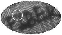
图2为实施例中实现可视化距离测量的原始观察图;Fig. 2 is the original observation diagram that realizes visual distance measurement in the embodiment;
图3为实施例中待测距离d与光斑中心在图像中横坐标的关系图;Fig. 3 is the relation diagram of the abscissa in the image between the distance to be measured d and the center of the light spot in the embodiment;
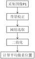
图4为实施例中测量光斑中心位置的提取算法流程图;Fig. 4 is the extraction algorithm flow chart of measuring the spot center position in the embodiment;
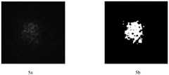
图5为实施例中测量光斑的原始图像和处理后图像,其中图5a为原始图像,图5b为处理后图像。Fig. 5 is the original image and the processed image of the measurement spot in the embodiment, wherein Fig. 5a is the original image, and Fig. 5b is the processed image.
具体实施方式Detailed ways
下面结合附图对本发明的技术方案作进一步说明。The technical solutions of the present invention will be further described below with reference to the accompanying drawings.
一种基于光纤束的内窥测距仪,包括内窥探头1和与之相连的激光发射模块 2、图像采集和处理模块3;所述内窥探头1包括第一光学透镜11、第二光学透镜 12、固定套管13、光纤束14和测量光纤15;所述激光发射模块2包含激光发射器21;所述图像采集和处理模块3包括第三光学透镜31、图像传感器32和处理器33;通过同心对准装置将第一光学透镜11的中心与光纤束14的中心进行同心对准后用粘合剂固定在一起,通过同心对准装置将第二光学透镜12的中心与测量光纤15的中心进行同心对准后用粘合剂固定在一起,利用粘合剂将两粘合体前端固定在特殊孔径的固定套管13中,其中第一光学透镜11和第二光学透镜12前端对齐且在具有一定的夹角,内窥探头1与激光发射模块2通过测量光纤15相连,内窥探头1与图像采集和处理模块3通过光纤束14相连;测量时,激光发射模块 2发出测量光通过测量光纤15、第二光学透镜12出射照射在物体上,第一光学透镜11和光纤束14将远端图像信息收集并传回,通过第三光学透镜31投影在图像传感器32上,处理器33通过图像处理算法将目标位置距离信息和远端图像信息分离提取,实现可视化测距。An endoscopic range finder based on an optical fiber bundle, comprising an endoscopic probe 1 and a
如图1所示,将准直透镜固定在单模光纤前端使得出射激光在一定测量区间保持较小光斑尺寸。光斑越小,测量位置更加精准。通过同心准直装置将准直透镜固定在光纤传像束的前端,以实现大景深成像,确保大动态范围的距离测量。光纤束后端通过准直透镜将光纤束近端图像信息投射在图像传感器上。As shown in Figure 1, the collimating lens is fixed at the front end of the single-mode fiber, so that the outgoing laser can maintain a small spot size in a certain measurement interval. The smaller the spot, the more accurate the measurement position. The collimating lens is fixed at the front end of the optical fiber image transmission beam by the concentric collimating device, so as to realize the imaging with a large depth of field and ensure the distance measurement with a large dynamic range. The rear end of the optical fiber bundle projects the image information of the near end of the optical fiber bundle on the image sensor through the collimating lens.
如图2所示,展示了使用本发明提供案例同时成像和距离测量的原始图像,白色圆圈标记了测量光斑位置。实时可视化成像有助于寻找目标测量位置,通过调整探头或物体位置,将测量光斑对准待测位置。通过与无测量光时拍摄的图像做差得到只含有测量光斑的图像信息。As shown in Fig. 2, the original image of simultaneous imaging and distance measurement using the case provided by the present invention is shown, and the white circle marks the position of the measurement spot. Real-time visual imaging helps to find the target measurement position, and adjust the position of the probe or object to align the measurement spot with the position to be measured. The image information containing only the measurement spot is obtained by making a difference with the image taken without the measurement light.
基于激光三角法,光斑在视场中的位置随着测量距离的变化而发生变化。如图3所示,通过对内窥探头前端参数计算得到待测距离d与光斑中心在图像中的横坐标X-pixel的理论曲线(“Theory”)并在不同距离处进行验证标定 (“Experiment”)。(同样也适用于纵坐标Y-pixel。)Based on laser triangulation, the position of the spot in the field of view changes with the measurement distance. As shown in Figure 3, the theoretical curve ("Theory") of the distance to be measured d and the abscissa X-pixel of the spot center in the image is obtained by calculating the front-end parameters of the endoscopic probe, and verification and calibration are performed at different distances ("Experiment"). ”). (The same applies to the ordinate Y-pixel.)
图像处理流程如图4所示,图像传感器记录的二维图像信息(包含距离信息) 如图5a所示散斑图,通过背景矫正、阈值选取、二值化处理和计算平均像素位置等步骤进行处理得到测量光斑中心所在图像中的坐标。二值化处理后结果如图5b 所示,计算其平均中心坐标为(X-pixel,Y-pixel),位置在图中用红点标注,将得到的像素坐标带入如图3所示曲线,计算得到该位置的待测距离。The image processing flow is shown in Figure 4. The two-dimensional image information (including distance information) recorded by the image sensor is shown in Figure 5a. The processing obtains the coordinates in the image where the center of the measurement spot is located. The result after binarization is shown in Figure 5b, the average center coordinate is calculated as (X-pixel, Y-pixel), the position is marked with a red dot in the figure, and the obtained pixel coordinates are brought into the curve shown in Figure 3 , and calculate the distance to be measured at the location.
Claims (10)
Priority Applications (1)
| Application Number | Priority Date | Filing Date | Title |
|---|---|---|---|
| CN202210309243.8ACN115143929A (en) | 2022-03-28 | 2022-03-28 | An Endoscopic Rangefinder Based on Fiber Bundle |
Applications Claiming Priority (1)
| Application Number | Priority Date | Filing Date | Title |
|---|---|---|---|
| CN202210309243.8ACN115143929A (en) | 2022-03-28 | 2022-03-28 | An Endoscopic Rangefinder Based on Fiber Bundle |
Publications (1)
| Publication Number | Publication Date |
|---|---|
| CN115143929Atrue CN115143929A (en) | 2022-10-04 |
Family
ID=83406675
Family Applications (1)
| Application Number | Title | Priority Date | Filing Date |
|---|---|---|---|
| CN202210309243.8APendingCN115143929A (en) | 2022-03-28 | 2022-03-28 | An Endoscopic Rangefinder Based on Fiber Bundle |
Country Status (1)
| Country | Link |
|---|---|
| CN (1) | CN115143929A (en) |
Citations (19)
| Publication number | Priority date | Publication date | Assignee | Title |
|---|---|---|---|---|
| JPS59151120A (en)* | 1983-02-17 | 1984-08-29 | Olympus Optical Co Ltd | Endoscope for measuring length |
| JP2002253488A (en)* | 2001-03-02 | 2002-09-10 | Asahi Optical Co Ltd | Endoscope device |
| JP2002360502A (en)* | 2001-06-11 | 2002-12-17 | Pentax Corp | Endoscope ranging device |
| JP2002365561A (en)* | 2001-06-11 | 2002-12-18 | Pentax Corp | Endoscope ranging device |
| US20050240077A1 (en)* | 2004-04-02 | 2005-10-27 | Jean Rovegno | Device for metrology by laser mapping for a videoendoscopic probe |
| CN101078772A (en)* | 2007-07-24 | 2007-11-28 | 华为技术有限公司 | Mobile terminal and method for measurement utilizing same |
| JP2008125996A (en)* | 2006-11-24 | 2008-06-05 | Pentax Corp | Endoscope subject distance measurement system |
| CN101305899A (en)* | 2008-07-09 | 2008-11-19 | 中国科学院上海光学精密机械研究所 | Three-dimensional endoscopic measurement device and method based on amplitude-type transmission grating projection |
| JP2014117446A (en)* | 2012-12-17 | 2014-06-30 | Olympus Corp | Insertion device |
| DE102014210619A1 (en)* | 2014-06-04 | 2015-12-17 | Olympus Winter & Ibe Gmbh | Endoscope with non-contact distance measurement |
| CN105377109A (en)* | 2013-03-14 | 2016-03-02 | 光圈诊断有限公司 | Full-field three dimensional surface measurement |
| CN106061358A (en)* | 2014-03-07 | 2016-10-26 | 西门子公司 | Endoscope with depth determination device |
| CN106574831A (en)* | 2014-07-10 | 2017-04-19 | 奥林巴斯株式会社 | Observation system |
| US20180003943A1 (en)* | 2016-06-29 | 2018-01-04 | Medical Intubation Technology Corporation | Endoscope with distance measurement function and distance measurement method used in same |
| CN108027238A (en)* | 2016-09-01 | 2018-05-11 | 索尼半导体解决方案公司 | Imaging device |
| CN110463174A (en)* | 2016-09-29 | 2019-11-15 | 美的洛博迪克斯公司 | Optical systems for surgical probes, systems and methods comprising the same, and methods for performing surgical procedures |
| CN111587384A (en)* | 2017-11-17 | 2020-08-25 | 特里纳米克斯股份有限公司 | Detector for determining a position of at least one object |
| CN213633984U (en)* | 2020-10-30 | 2021-07-06 | 武汉中仪物联技术股份有限公司 | Pipeline periscope |
| CN114207499A (en)* | 2019-08-13 | 2022-03-18 | 富士胶片株式会社 | Endoscope system and its working method |
- 2022
- 2022-03-28CNCN202210309243.8Apatent/CN115143929A/enactivePending
Patent Citations (19)
| Publication number | Priority date | Publication date | Assignee | Title |
|---|---|---|---|---|
| JPS59151120A (en)* | 1983-02-17 | 1984-08-29 | Olympus Optical Co Ltd | Endoscope for measuring length |
| JP2002253488A (en)* | 2001-03-02 | 2002-09-10 | Asahi Optical Co Ltd | Endoscope device |
| JP2002360502A (en)* | 2001-06-11 | 2002-12-17 | Pentax Corp | Endoscope ranging device |
| JP2002365561A (en)* | 2001-06-11 | 2002-12-18 | Pentax Corp | Endoscope ranging device |
| US20050240077A1 (en)* | 2004-04-02 | 2005-10-27 | Jean Rovegno | Device for metrology by laser mapping for a videoendoscopic probe |
| JP2008125996A (en)* | 2006-11-24 | 2008-06-05 | Pentax Corp | Endoscope subject distance measurement system |
| CN101078772A (en)* | 2007-07-24 | 2007-11-28 | 华为技术有限公司 | Mobile terminal and method for measurement utilizing same |
| CN101305899A (en)* | 2008-07-09 | 2008-11-19 | 中国科学院上海光学精密机械研究所 | Three-dimensional endoscopic measurement device and method based on amplitude-type transmission grating projection |
| JP2014117446A (en)* | 2012-12-17 | 2014-06-30 | Olympus Corp | Insertion device |
| CN105377109A (en)* | 2013-03-14 | 2016-03-02 | 光圈诊断有限公司 | Full-field three dimensional surface measurement |
| CN106061358A (en)* | 2014-03-07 | 2016-10-26 | 西门子公司 | Endoscope with depth determination device |
| DE102014210619A1 (en)* | 2014-06-04 | 2015-12-17 | Olympus Winter & Ibe Gmbh | Endoscope with non-contact distance measurement |
| CN106574831A (en)* | 2014-07-10 | 2017-04-19 | 奥林巴斯株式会社 | Observation system |
| US20180003943A1 (en)* | 2016-06-29 | 2018-01-04 | Medical Intubation Technology Corporation | Endoscope with distance measurement function and distance measurement method used in same |
| CN108027238A (en)* | 2016-09-01 | 2018-05-11 | 索尼半导体解决方案公司 | Imaging device |
| CN110463174A (en)* | 2016-09-29 | 2019-11-15 | 美的洛博迪克斯公司 | Optical systems for surgical probes, systems and methods comprising the same, and methods for performing surgical procedures |
| CN111587384A (en)* | 2017-11-17 | 2020-08-25 | 特里纳米克斯股份有限公司 | Detector for determining a position of at least one object |
| CN114207499A (en)* | 2019-08-13 | 2022-03-18 | 富士胶片株式会社 | Endoscope system and its working method |
| CN213633984U (en)* | 2020-10-30 | 2021-07-06 | 武汉中仪物联技术股份有限公司 | Pipeline periscope |
Similar Documents
| Publication | Publication Date | Title |
|---|---|---|
| CN105066909B (en) | A kind of many laser stripe quick three-dimensional measuring methods of hand-held | |
| CN103492870B (en) | Cooperate with the long-range projector with the six degree of freedom laser traces device of mail message | |
| US9163922B2 (en) | Coordinate measurement machine with distance meter and camera to determine dimensions within camera images | |
| JP4871352B2 (en) | Automatic reference system and apparatus for 3D scanning | |
| CN106595519B (en) | A kind of flexible 3 D contour measuring method and device based on laser MEMS projection | |
| Ribo et al. | State of the art on vision-based structured light systems for 3D measurements | |
| CN102853786A (en) | Apparatus and method for detecting flatness | |
| EP0398563A2 (en) | Fiber optic triangulation gage | |
| CN116908217B (en) | Deep hole measurement and three-dimensional reconstruction system and application method thereof | |
| CN105004324A (en) | Monocular vision sensor with triangulation ranging function | |
| CN106767545A (en) | A kind of high accuracy high-space resolution angel measuring instrument and angle measurement method | |
| Jin et al. | Accurate intrinsic calibration of depth camera with cuboids | |
| CN105444729A (en) | Method for measuring optical long distance | |
| Matthias et al. | A 3D measuring endoscope for hand-guided operation | |
| JPH02184715A (en) | Distance measuring apparatus and method | |
| CN115143929A (en) | An Endoscopic Rangefinder Based on Fiber Bundle | |
| CN109978953A (en) | Method and system for target three-dimensional localization | |
| CN206311075U (en) | A kind of heavy caliber Precise outline measuring system | |
| CN117629567A (en) | High instantaneous speed model attitude angle online measurement method | |
| D’Amelio et al. | Close range photogrammetry for measurement of paintings surface deformations | |
| CN115239823A (en) | An underwater three-dimensional point cloud measurement method, electronic device and storage medium | |
| EP2123214A1 (en) | A probing device and a system for obtaining geometrical data related to a cavity | |
| CN111207691A (en) | Method for realizing measurement of optical fiber shape | |
| CN204468088U (en) | A kind of Measurement of surface deepth device | |
| JP6097123B2 (en) | 3D measurement system |
Legal Events
| Date | Code | Title | Description |
|---|---|---|---|
| PB01 | Publication | ||
| PB01 | Publication | ||
| SE01 | Entry into force of request for substantive examination | ||
| SE01 | Entry into force of request for substantive examination | ||
| RJ01 | Rejection of invention patent application after publication | Application publication date:20221004 |