Movatterモバイル変換


[0]ホーム

URL:


CN115139026B - Automatic welding line and welding method for automobile front wall plate - Google Patents

Automatic welding line and welding method for automobile front wall plate
Download PDF

Info

Publication number
CN115139026B
CN115139026BCN202211067507.XACN202211067507ACN115139026BCN 115139026 BCN115139026 BCN 115139026BCN 202211067507 ACN202211067507 ACN 202211067507ACN 115139026 BCN115139026 BCN 115139026B
Authority
CN
China
Prior art keywords
plate
cylinder
positioning
welding
rotating
Prior art date
Legal status (The legal status is an assumption and is not a legal conclusion. Google has not performed a legal analysis and makes no representation as to the accuracy of the status listed.)
Active
Application number
CN202211067507.XA
Other languages
Chinese (zh)
Other versions
CN115139026A (en
Inventor
黄庆财
吴高灿
方钦杰
Current Assignee (The listed assignees may be inaccurate. Google has not performed a legal analysis and makes no representation or warranty as to the accuracy of the list.)
Guangzhou Fuji Auto Assembly Co ltd
Original Assignee
Guangzhou Fuji Auto Assembly Co ltd
Priority date (The priority date is an assumption and is not a legal conclusion. Google has not performed a legal analysis and makes no representation as to the accuracy of the date listed.)
Filing date
Publication date
Application filed by Guangzhou Fuji Auto Assembly Co ltdfiledCriticalGuangzhou Fuji Auto Assembly Co ltd
Priority to CN202211335230.4ApriorityCriticalpatent/CN115625454B/en
Priority to CN202211337006.9Aprioritypatent/CN115625455B/en
Priority to CN202211067507.XAprioritypatent/CN115139026B/en
Publication of CN115139026ApublicationCriticalpatent/CN115139026A/en
Application grantedgrantedCritical
Publication of CN115139026BpublicationCriticalpatent/CN115139026B/en
Activelegal-statusCriticalCurrent
Anticipated expirationlegal-statusCritical

Links

Images

Classifications

Landscapes

Abstract

The invention discloses an automatic welding line for a front wall plate of an automobile, which has the technical scheme that the welding line comprises two input accumulation chains, a plurality of carrying robots, a plurality of repair welding tables, a plurality of welding robots, a plurality of fixed welding gun positions, a plurality of transfer tables, a rotating table and the like. The welding method comprises the steps that a main body plate is conveyed through a first input accumulated and released chain, a first auxiliary plate is conveyed through a second input accumulated and released chain, the main body plate and the first auxiliary plate are conveyed to a first repair welding table for first welding through a first conveying robot, the first welding plate is conveyed to a first fixed welding gun position by a second conveying robot for second welding, the second welding plate is conveyed to a first transfer table by the second conveying robot, the second welding plate is conveyed to a stud welding position by a third conveying robot for third welding, multiple welding is carried out subsequently, and finally the welding plate is conveyed to the next procedure through an output accumulated and released chain.

Description

Translated fromChinese
一种汽车前围板自动化焊接线及其焊接方法Automated welding line and welding method for automobile dash panel

技术领域technical field

本发明涉及一种汽车前围板自动化焊接线及其焊接方法。The invention relates to an automatic welding line and a welding method for an automobile dash panel.

背景技术Background technique

汽车产业是我国的支柱产业之一,车身板件则是汽车的核心部件之一。目前车身制造是按照下车身总成平台车型进行细分,不同的生产基地生产不同的细分车型。其缺点在于当前的车身总成焊接生产线仅仅能实现单一车型的焊接生产,无法实现多车型混线生产,新增车型或改款车型时需要新建或改造线体,周期很长,投入成本巨大,也大大降低了生产效率。The automobile industry is one of the pillar industries of our country, and the body panel is one of the core components of the automobile. At present, body manufacturing is subdivided according to the lower body assembly platform models, and different production bases produce different subdivided models. Its disadvantage is that the current body assembly welding production line can only realize the welding production of a single model, and cannot realize the mixed production of multiple models. When adding a new model or changing a model, it is necessary to build or modify the line body. The cycle is very long and the input cost is huge. Also greatly reduced production efficiency.

发明内容Contents of the invention

本发明目的是克服了现有技术的不足,提供一种汽车前围板自动化焊接线及其焊接方法,以缓解现有技术中存在的车身焊接生产线仅仅能实现单一车型的焊接生产,无法实现多车型混线生产的技术问题,大大提高效率。The object of the present invention is to overcome the deficiencies of the prior art, and provide an automatic welding line and its welding method for the front panel of the automobile, so as to alleviate the existing welding production line of the car body in the prior art, which can only realize the welding production of a single vehicle type, and cannot realize multiple The technical problems of the mixed-line production of models have greatly improved efficiency.

本发明是通过以下技术方案实现的:The present invention is achieved through the following technical solutions:

一种汽车前围板自动化焊接线,其特征在于包括有:An automatic welding line for an automobile dash panel, characterized in that it comprises:

第一输入积放链13:用于输送前围下板12;The first input accumulating chain 13: used for conveying the cowllower panel 12;

第二输入积放链14:用于输送前围上板11;The second input accumulation chain 14: used for conveying the cowlupper panel 11;

第一搬运机器人9:用于分别搬运前围下板12和前围上板11;The first transport robot 9: used to transport the cowllower panel 12 and the cowlupper panel 11 respectively;

第一焊接台7:用于承载第一搬运机器人9搬运过来的前围下板12和前围上板11;The first welding station 7: used to carry the cowllower panel 12 and the cowlupper panel 11 transported by thefirst handling robot 9;

第一焊接机器人8:用于在第一焊接台7上将前围下板12和前围上板11焊接成前围下板组件;The first welding robot 8: for welding the cowllower panel 12 and the cowlupper panel 11 on thefirst welding station 7 to form the cowl lower panel assembly;

第一固定焊枪位15:用于第二次焊接从第一焊接台7转运过来的前围下板组件;The first fixed welding torch position 15: used for the second welding of the cowl lower plate assembly transferred from thefirst welding station 7;

第一中转台16:用于转运从第一固定焊枪位15搬运过来的前围下板组件;The first transfer platform 16: used to transfer the cowl lower panel assembly transported from the first fixedwelding torch position 15;

第二搬运机器人10:用于搬运第一焊接台7或第一固定焊枪位15上的板件;The second handling robot 10: used to transport the plate on thefirst welding station 7 or the first fixedwelding torch position 15;

螺柱焊接位17:用于第三次焊接从第一中转台16搬运过来的前围下板组件;Stud welding position 17: used for the third welding of the cowl lower plate assembly transported from the first transfer table 16;

第三搬运机器人19:用于将第一中转台16上的前围下板组件搬运至螺柱焊接位17,或者将螺柱焊接位17上的前围下板组件搬运至旋转台18;The third transport robot 19: used to transport the cowl lower panel assembly on thefirst transfer platform 16 to thestud welding position 17, or transport the cowl lower panel assembly on thestud welding position 17 to the rotary table 18;

旋转台18:能360度水平转动、用于承载螺柱焊接位17转运过来的前围下板组件与前围上盖板27;Rotary table 18: capable of 360-degree horizontal rotation, used to carry the cowl lower plate assembly and the cowlupper cover plate 27 transferred from thestud welding position 17;

第二焊接机器人20:设在旋转台18的外端两侧用于将前围下板组件与人工上件的前围上盖板27焊接形成前围板总成,第二焊接机器人20设有两台,分别设在旋转台18外端的两侧;The second welding robot 20: set on both sides of the outer end of the rotary table 18 for welding the cowl lower panel assembly and the cowlupper cover plate 27 of the manual upper part to form the cowl assembly. Thesecond welding robot 20 is equipped with Two sets are respectively arranged on both sides of the outer end of the rotary table 18;

第三焊接机器人21:设在旋转台18的内端两侧待旋转台18旋转回来时将前围下板组件与前围上盖板27连接的另一面焊接,第三焊接机器人21也设有两台,分别设在旋转台18内端的两侧;The third welding robot 21: it is arranged on both sides of the inner end of the rotary table 18. When the rotary table 18 is rotated back, the other side of the cowl lower panel assembly and the cowlupper cover 27 is connected to weld. Thethird welding robot 21 is also provided with Two sets are respectively arranged on both sides of the inner end of the rotary table 18;

第二固定焊枪位22:用于将旋转台18转运过来的前围板总成进行第三次焊接;The second fixed welding torch position 22: used for the third welding of the dash panel assembly transferred from the rotary table 18;

第二中转台23:用于接收从第二固定焊枪位22转运过来的前围板总成;The second transfer platform 23: used to receive the dash panel assembly transferred from the second fixedwelding torch position 22;

第四搬运机器人24:用于将第二固定焊枪位22上的前围板总成搬运到第二中转台23上;The fourth transport robot 24: used to transport the dash panel assembly on the second fixedwelding torch position 22 to thesecond transfer platform 23;

检查台26:用于接收从第二中转台23转运过来的前围板总成并进行人工检查;Inspection platform 26: used to receive the dashboard assembly transferred from thesecond transfer platform 23 and perform manual inspection;

第五搬运机器人25:用于将第二中转台23上的前围板总成搬运至检查台26,然后将检查台26上的前围板总成搬运至输出积放链29,或者直接将第二中转台23上的前围板总成搬运至输出积放链29;The fifth transport robot 25: used to transport the cowl assembly on thesecond transfer platform 23 to theinspection platform 26, and then transport the cowl assembly on theinspection platform 26 to theoutput accumulation chain 29, or directly The dash panel assembly on thesecond transfer platform 23 is transported to theoutput accumulating chain 29;

输出积放链29:用于将焊接好的前围板总成输送至下一工序。Output accumulation chain 29: used to transport the welded dash panel assembly to the next process.

如上所述的汽车前围板自动化焊接线,其特征在于:在所述第二搬运机器人10的抓手上设有用于定位板件的剪刀叉装置1,所述剪刀叉装置1包括第一滑动机构、被第一滑动机构驱动滑动的第一旋转机构、被第一旋转机构驱动转动的第一勾销缸机构,所述第一滑动机构包括第一滑轨101、被第一气缸102驱动能沿第一滑轨101滑动的第一滑动板103,在所述第一滑动板103上设有多个安装板116;所述第一旋转机构包括固定在其中一个所述安装板116上的第四固定架117,在第四固定架117上分别设有第一铰接点104和第二铰接点105,在第四固定架117上还设有能绕第一铰接点104转动的第二气缸106、被第二气缸106驱动能绕第二铰接点105转动的第一旋转板107。The automatic welding line for the automobile dash panel as described above is characterized in that: a scissor-fork device 1 for positioning panels is provided on the gripper of thesecond handling robot 10, and the scissor-fork device 1 includes a first slide mechanism, the first rotating mechanism driven to slide by the first sliding mechanism, and the first detent cylinder mechanism driven to rotate by the first rotating mechanism. The firstsliding plate 103 that thefirst slide rail 101 slides is provided with a plurality ofmounting plates 116 on the firstsliding plate 103; the first rotating mechanism includes afourth mounting plate 116 fixed on one of them. Fixedmount 117 is respectively provided withfirst hinge point 104 andsecond hinge point 105 on the fourth fixedmount 117, is also provided with thesecond air cylinder 106 that can rotate aroundfirst hinge point 104 on the fourth fixedmount 117, The firstrotary plate 107 that can rotate around thesecond hinge point 105 is driven by thesecond cylinder 106 .

如上所述的汽车前围板自动化焊接线,其特征在于:所述第一勾销缸机构包括设在第一旋转板107上的第三气缸110,在第一旋转板107上且位于第三气缸110的上方设有第一定位销112,所述第一定位销112由两块板通过固定销114连接组成,第一定位销112的顶部呈锥形,组成第一定位销112的两块板之间设有两个对称、且被第三气缸110驱动升降的定位勾111,第三气缸110的活塞杆与两定位勾111的底端铰接,在定位勾111上设有第一限位孔113,所述固定销114从两个定位勾111的第一限位孔113穿过,所述第一限位孔113包括竖直的上部孔和沿内侧倾斜的下部孔,上部孔和下部孔连通,在第一定位销112的锥形顶部外侧设有环形台阶115,被驱动下降的定位勾111夹于所述环形台阶115上。The above-mentioned automatic welding line for the front wall of the automobile is characterized in that: the first detent cylinder mechanism includes athird cylinder 110 arranged on the first rotatingplate 107, and the third cylinder is located on the first rotatingplate 107 The top of 110 is provided withfirst positioning pin 112, and describedfirst positioning pin 112 is formed by connecting two plates throughfixing pin 114, and the top offirst positioning pin 112 is conical, and the two plates that formfirst positioning pin 112 There are twosymmetrical positioning hooks 111 that are driven up and down by thethird cylinder 110, the piston rod of thethird cylinder 110 is hinged with the bottom ends of the twopositioning hooks 111, and thepositioning hook 111 is provided with afirst limit hole 113, thefixed pin 114 passes through the first limitinghole 113 of the twopositioning hooks 111, the first limitinghole 113 includes a vertical upper hole and a lower hole inclined along the inner side, the upper hole and the lower hole In communication, anannular step 115 is provided outside the conical top of thefirst positioning pin 112 , and thepositioning hook 111 driven to descend is clamped on theannular step 115 .

如上所述的汽车前围板自动化焊接线,其特征在于:在所述第一焊接台7上设有对板件定位的第一定位装置2,所述第一定位装置2包括第一固定架201,在第一固定架201上设有第二滑轨202、能沿第二滑轨202滑动的第二滑动板203、驱动第二滑动板203上下滑动的第四气缸204,在第二滑动板203上设有下安装位和上安装位,在所述下安装位上分别设有第五固定架214和第五气缸208,在第五固定架214上分别设有第三铰接点207、被第五气缸208驱动绕第三铰接点207转动的第二旋转板206,在所述第二旋转板206上分别设有第十三气缸205以及由第十三气缸205驱动升降的第一固定板209,在第一固定板209的侧面固定连接有第一固定块210,在第一固定块210上设有能够从板件上的孔穿出从而对板件定位的第二定位销211;在第二旋转板206上还设有分别对板件侧向定位的第一定位块212、第一板件感应器213。The above-mentioned automatic welding line for the front panel of the automobile is characterized in that: thefirst positioning device 2 for positioning the plate is provided on thefirst welding station 7, and thefirst positioning device 2 includes afirst fixing frame 201, asecond slide rail 202, asecond slide plate 203 capable of sliding along thesecond slide rail 202, afourth cylinder 204 that drives thesecond slide plate 203 to slide up and down are provided on the firstfixed frame 201, and the second slide Theboard 203 is provided with a lower installation position and an upper installation position, and a fifth fixedframe 214 and afifth cylinder 208 are respectively arranged on the lower installed position, and athird hinge point 207, athird hinge point 207, The second rotatingplate 206 driven by thefifth cylinder 208 to rotate around thethird hinge point 207 is respectively provided with thethirteenth cylinder 205 and the first fixed cylinder driven up and down by thethirteenth cylinder 205 . Theplate 209 is fixedly connected with the firstfixed block 210 on the side of the firstfixed plate 209, and thesecond positioning pin 211 that can pass through the hole on the plate to position the plate is provided on the firstfixed block 210; Afirst positioning block 212 and afirst board sensor 213 for laterally positioning the board are also provided on the second rotatingboard 206 .

如上所述的汽车前围板自动化焊接线,其特征在于:在所述第一搬运机器人9的抓手上设有能对两种板件定位的第三定位装置4,所述第三定位装置4包括第三固定架401,在第三固定架401上设有第三滑轨402、能沿第三滑轨402上下滑动的第三滑动板403、驱动第三滑动板403滑动的第九气缸404,在第三滑动板403上设有第五铰接点405、能绕第五铰接点405旋转的第三旋转板406、用于驱动第三旋转板406转动的第十气缸407,在第三旋转板406上固定连接有第四旋转板408,在第三旋转板406的外端设有在第十气缸407的活塞杆缩回时对所述板件的底面定位的第五定位块409,在第四旋转板408的外端设有在第十气缸407的活塞杆上升时对另一种板件定位的第三定位销411。The automatic welding line for the front panel of the automobile as described above is characterized in that: the gripper of thefirst transfer robot 9 is provided with athird positioning device 4 capable of positioning two kinds of panels, and thethird positioning device 4. It includes a third fixedframe 401, on which a third slidingrail 402, a thirdsliding plate 403 capable of sliding up and down along the third slidingrail 402, and a ninth cylinder for driving the thirdsliding plate 403 to slide are arranged on the third fixedframe 401 404, the thirdsliding plate 403 is provided with afifth hinge point 405, a third rotatingplate 406 capable of rotating around thefifth hinge point 405, and atenth cylinder 407 for driving the third rotatingplate 406 to rotate. The fourth rotatingplate 408 is fixedly connected to therotating plate 406, and the outer end of the third rotatingplate 406 is provided with afifth positioning block 409 for positioning the bottom surface of the plate when the piston rod of thetenth cylinder 407 is retracted. The outer end of the fourth rotatingplate 408 is provided with athird positioning pin 411 for positioning another plate when the piston rod of thetenth cylinder 407 rises.

如上所述的汽车前围板自动化焊接线,其特征在于:在所述旋转台18上设有对多种板件定位的第二定位装置3,所述第二定位装置3包括有下压装置、用于带动第一上托块B312作升降运动的第一上托机构B、用于带动第二上托块B313作旋转运动的第二旋转上托机构B、用于带动第三上托块1A314和第三上托块2A315作升降运动的第三上托机构A、用于带动第四上托块A316作旋转运动的第四旋转上托机构A;下压装置又包括用于带动旋转架303转动的第二旋转机构、第二下压机构B、第四下压机构A、第一旋转下压机构B、第三下压机构A,其中第二下压机构B、第四下压机构A、第一旋转下压机构B、第三下压机构A又分别设在第二旋转机构上。The above-mentioned automatic welding line for the front panel of the automobile is characterized in that: thesecond positioning device 3 for positioning various panels is provided on the rotary table 18, and thesecond positioning device 3 includes a pressing device , The first lifting mechanism B used to drive the first upper bracket B312 for lifting movement, the second rotating upper bracket B for driving the second upper bracket B313 to rotate, and the third upper bracket B for driving 1A314 and the third upper supporting block 2A315 for the third lifting mechanism A, the fourth rotating supporting mechanism A for driving the fourth upper supporting block A316 to rotate; 303 rotation of the second rotating mechanism, the second pressing mechanism B, the fourth pressing mechanism A, the first rotating pressing mechanism B, the third pressing mechanism A, wherein the second pressing mechanism B, the fourth pressing mechanism A, the first rotating pressing mechanism B, and the third pressing mechanism A are respectively arranged on the second rotating mechanism.

如上所述的汽车前围板自动化焊接线,其特征在于:所述第二旋转机构包括第二固定架301,在第二固定架301上分别设有第四铰接点302、能绕第四铰接点302旋转的旋转架303、用于驱动旋转架303转动的第六气缸304;在所述旋转架303上的左右两侧分别设有吊架305,在吊架305上设有多个安装位,在其中一个安装位设有带动第二下压块B307作升降运动的第二下压机构B,在另一个安装位上设有带动第四下压块A308作升降运动的第四下压机构A;在旋转架303的自由端设有托板306,在所述托板306上设有多个安装位,在其中一个安装位设有带动第一下压块B309转动的第一旋转下压机构B,在另一个安装位上设有带动第三下压块1A310和第三下压块2A311作升降运动的第三下压机构A。The above-mentioned automatic welding line for the front wall of the automobile is characterized in that: the second rotating mechanism includes asecond fixing frame 301, and thefourth hinge point 302 is respectively provided on thesecond fixing frame 301, and can be articulated around the fourth hinge The rotatingframe 303 that rotates atpoint 302, thesixth cylinder 304 that is used to drive the rotatingframe 303 to rotate; the left and right sides on the describedrotating frame 303 are respectively provided with ahanger 305, and a plurality of installation positions are arranged on thehanger 305 , one of the installation positions is provided with a second pressing mechanism B that drives the second pressing block B307 for lifting movement, and the other installation position is provided with a fourth pressing mechanism B that drives the fourth pressing block A308 for lifting movement A: A supportingplate 306 is provided at the free end of the rotatingframe 303, and a plurality of mounting positions are provided on the supportingplate 306, and a first rotating pressing block that drives the first pressing block B309 to rotate is provided at one of the mounting positions. Mechanism B is provided with a third pressing mechanism A that drives the third pressing block 1A310 and the third pressing block 2A311 to move up and down on another installation position.

如上所述的汽车前围板自动化焊接线,其特征在于:所述第二下压机构B包括有设在所述吊架305一个安装位上的第七气缸322、由第七气缸322驱动的第二下压块B307;The above-mentioned automatic welding line for the front panel of the automobile is characterized in that: the second pressing mechanism B includes aseventh cylinder 322 which is arranged on a mounting position of thehanger 305, and a cylinder driven by theseventh cylinder 322. The second pressing block B307;

所述第四下压机构A包括有设在所述吊架305另一个安装位上的第十四气缸317、由第十四气缸317驱动的第四下压块A308,所述第十四气缸317与所述第七气缸322设在所述吊架305的同一侧;The fourth depressing mechanism A includes afourteenth cylinder 317 located on another mounting position of thehanger 305, a fourth depressing block A308 driven by thefourteenth cylinder 317, and thefourteenth cylinder 317 and theseventh cylinder 322 are arranged on the same side of thehanger 305;

所述第一旋转下压机构B包括有固定在所述托板306其中一个安装位上的第二固定板318,在所述第二固定板318上水平设有第十六气缸319,第十六气缸319的活塞杆沿水平方向伸缩,第十六气缸319的活塞杆铰接有第十四旋转板320,在第十四旋转板320的自由端底面设有第一下压块B309;The first rotary pressing mechanism B includes asecond fixing plate 318 fixed on one of the mounting positions of the supportingplate 306, and asixteenth cylinder 319 is horizontally arranged on thesecond fixing plate 318. The piston rod of the sixcylinders 319 expands and contracts in the horizontal direction, the piston rod of thesixteenth cylinder 319 is hinged to a fourteenthrotating plate 320, and a first lower pressing block B309 is provided on the bottom surface of the free end of the fourteenth rotatingplate 320;

所述第三下压机构A包括固定在所述另一个安装位上的第三固定板321,在所述第三固定板321上设有第十九气缸323、由第十九气缸323驱动升降的第三下压块1A310和第三下压块2A311;The third depressing mechanism A includes a thirdfixed plate 321 fixed on the other installation position, and anineteenth cylinder 323 is arranged on the third fixedplate 321, and thenineteenth cylinder 323 drives up and down. The third lower pressing block 1A310 and the third lower pressing block 2A311;

所述第一上托机构B包括固定在第六固定架33上的第一升降气缸324、被第一升降气缸324驱动升降的第一上托块B312;The first lifting mechanism B includes afirst lifting cylinder 324 fixed on the sixthfixed frame 33, and a first lifting block B312 driven up and down by thefirst lifting cylinder 324;

所述第二旋转上托机构B包括固定在第十固定架327上的第十一固定板328,在所述第十一固定板328上分别铰接有第十七气缸329、被第十七气缸329驱动转动的第十三旋转板330,在第十三旋转板330的自由端设有第二上托块B313;The second rotating lifting mechanism B includes aneleventh fixing plate 328 fixed on thetenth fixing frame 327, on which theseventeenth cylinder 329 is respectively hinged, and theseventeenth cylinder 329 drives the thirteenthrotating plate 330 to rotate, and the free end of the thirteenth rotatingplate 330 is provided with a second upper bracket B313;

所述第三上托机构A包括有设在第十一固定架331上的第十八气缸332、被第十八气缸332驱动升降的第十二固定板333,在所述第十二固定板333的顶部分别设有第三上托块1A314和第三上托块2A315;The third lifting mechanism A includes aneighteenth cylinder 332 arranged on the eleventhfixed frame 331, a twelfth fixedplate 333 driven up and down by theeighteenth cylinder 332, and the twelfth fixed plate The top of 333 is respectively provided with a third upper bracket 1A314 and a third upper bracket 2A315;

所述第四旋转上托机构A的结构与第二旋转上托机构B的结构相同。The structure of the fourth rotating lifting mechanism A is the same as that of the second rotating lifting mechanism B.

如上所述的汽车前围板自动化焊接线,其特征在于:所述第二定位装置3还包括有第二定位机构B6,第二定位机构B6包括有固定在第六固定架33上的第二升降气缸601、被第二升降气缸601驱动升降的第七固定板602,在第七固定板602上固定有第二支撑板603,在第二支撑板603上分别铰接有第二十气缸604、由第二十气缸604驱动绕第八铰接点605转动的第八旋转板606,在所述第八旋转板606上分别铰接有第十五气缸607、由第十五气缸607驱动绕第九铰接点608转动的第九旋转板610,在第九旋转板610上设有第一连接板609,在第一连接板609上从下至上分别设有第一下定位块611、第一上定位块612,在第八旋转板606上由下至上分别设有第二下定位块613、第二上定位块614。The above-mentioned automatic welding line for the front panel of the automobile is characterized in that: thesecond positioning device 3 also includes a second positioning mechanism B6, and the second positioning mechanism B6 includes a second positioning mechanism fixed on thesixth fixing bracket 33.Lifting cylinder 601, the seventh fixedplate 602 driven up and down by thesecond lifting cylinder 601, thesecond support plate 603 is fixed on the seventhfixed plate 602, and thetwentieth cylinder 604, The eighth rotatingplate 606 driven by thetwentieth cylinder 604 to rotate around theeighth hinge point 605 is respectively hinged with thefifteenth cylinder 607, which is driven by thefifteenth cylinder 607 and hinged around theninth hinge point 605. The ninthrotating plate 610 that rotates atpoint 608 is provided with a first connectingplate 609 on the ninth rotatingplate 610, and is respectively provided with a firstlower positioning block 611 and a first upper positioning block on the first connectingplate 609 from bottom to top. 612, a secondlower positioning block 613 and a secondupper positioning block 614 are respectively provided on the eighth rotatingplate 606 from bottom to top.

一种如上所述的汽车前围板自动化焊接线焊接的方法,其特征在于包括有:A method for automatic welding line welding of an automobile dash panel as described above, characterized in that it includes:

通过第一输入积放链13输送上一工序的前围下板12,通过第二输入积放链14输送人工放入的前围上板11,通过第一搬运机器人9分别将一块前围下板12和一块前围上板11搬运至第一焊接台7,通过第一焊接机器人8将第一焊接台7上的一块前围下板12和一块前围上板11一次焊接形成前围下板组件,第二搬运机器人10将前围下板组件转运至第一固定焊枪位15进行二次焊接,第二搬运机器人10将二次焊接后的前围下板组件转运至第一中转台16,第三搬运机器人19将第一中转台16上的前围下板组件搬运至螺柱焊接位17进行第三次焊接;The cowllower panel 12 of the previous process is conveyed by the firstinput accumulating chain 13, the cowlupper panel 11 put in manually is conveyed by the secondinput accumulating chain 14, and a cowl lower panel is respectively removed by thefirst transfer robot 9. Thepanel 12 and a cowlupper panel 11 are transported to thefirst welding station 7, and a cowllower panel 12 and a cowlupper panel 11 on thefirst welding station 7 are welded at one time by thefirst welding robot 8 to form the cowl lower panel. Panel assembly, thesecond transfer robot 10 transfers the cowl lower panel assembly to the first fixedwelding torch position 15 for secondary welding, and thesecond transfer robot 10 transfers the cowl lower panel assembly after secondary welding to thefirst transfer station 16 , thethird transfer robot 19 transfers the cowl lower panel assembly on thefirst transfer platform 16 to thestud welding position 17 for the third welding;

第三搬运机器人19将三次焊接后的前围下板组件搬运至旋转台18的内端,旋转台18水平旋转180度将内端的前围下板组件旋转至外端与人工上料的前围上盖板27通过两台第二焊接机器人20进行第四次焊接形成前围板总成,也是前围板总成的第一次焊接,此时焊接的是前围下板组件与前围上盖板27连接的其中一面,然后旋转台18旋转180度转回内端,两台第三焊接机器人21对前围板总成进行第二次焊接,此时焊接的是前围下板组件与前围上盖板27连接的另一面;Thethird handling robot 19 transports the cowl lower panel assembly welded three times to the inner end of the rotary table 18, and the rotary table 18 horizontally rotates 180 degrees to rotate the inner cowl lower panel assembly to the outer end and manually load the cowl assembly. Theupper cover plate 27 is welded for the fourth time by twosecond welding robots 20 to form the dash panel assembly, which is also the first welding of the dash panel assembly. At this time, the dash lower panel assembly and the dash upper panel are welded One side of thecover plate 27 is connected, and then the rotary table 18 is rotated 180 degrees to turn back to the inner end, and the twothird welding robots 21 perform the second welding on the dash panel assembly. The other side connected to thecowl top cover 27;

第四搬运机器人24将旋转台18上二次焊接的前围板总成搬运至第二固定焊枪位22进行第三次焊接,第四搬运机器人24将三次焊接后的前围板总成搬运至第二中转台23;第五搬运机器人25将第二中转台23上的前围板总成搬运至检查台26人工检查,质量符合要求的由第五搬运机器人25搬运至输出积放链29,通过输出积放链29输送至下一工序;Thefourth transport robot 24 transports the dash panel assembly welded for the second time on the rotary table 18 to the second fixedwelding torch position 22 for the third welding, and thefourth transport robot 24 transports the dash panel assembly welded three times to Thesecond transfer platform 23; thefifth transport robot 25 transports the dash panel assembly on thesecond transfer platform 23 to the inspection table 26 for manual inspection, and thefifth transport robot 25 transports the products that meet the requirements to theoutput accumulation chain 29, Delivered to the next process by theoutput accumulation chain 29;

当板件转运至旋转台18时,通过以下方法夹紧板件:When the panels are transferred to the rotary table 18, the panels are clamped by:

要夹紧a型前围板总成28-a时,第三下压机构A中的第十九气缸323驱动第三下压块1A310和第三下压块2A311下降,第三上托机构A中的第十八气缸332驱动第三上托块1A314和第三上托块2A315上升分别与第三下压块1A310和第三下压块2A311配合;第四下压机构A中的第十四气缸317驱动第四下压块A308下降,第四旋转上托机构A驱动第四上托块A316上升与第四下压块A308配合,同时用于夹紧b型前围板总成28-b的机构主动避让,避让的动作与夹紧的动作刚好相反;When the a-type dash panel assembly 28-a is to be clamped, thenineteenth cylinder 323 in the third pressing mechanism A drives the third pressing block 1A310 and the third pressing block 2A311 to descend, and the third lifting mechanism A Theeighteenth cylinder 332 in the drive drives the third upper block 1A314 and the third upper block 2A315 to rise to cooperate with the third lower block 1A310 and the third lower block 2A311 respectively;Cylinder 317 drives the fourth lower pressing block A308 to descend, and the fourth rotating upper supporting mechanism A drives the fourth upper supporting block A316 to rise to cooperate with the fourth lower pressing block A308, and is used to clamp the b-shaped dash panel assembly 28-b at the same time The mechanism actively avoids, and the avoiding action is just opposite to the clamping action;

要夹紧b型前围板总成28-b时,第一旋转下压机构B中的第十六气缸319驱动第一下压块B309旋转下降,第一上托机构B中的第一升降气缸324驱动第一上托块B312上升与第一下压块B309配合,第二下压机构B中的第七气缸322驱动第二下压块B307下降,第二旋转上托机构B中的第十七气缸329驱动第二上托块B313上升与第二下压块B307配合,第二定位机构B6中的第二升降气缸601、第二十气缸604、第十五气缸607先后动作使得第一下定位块611和第一上定位块612分别与第二下定位块613和第二上定位块614,同时用于夹紧a型前围板总成28-a的机构主动避让,避让的动作与夹紧的动作刚好相反。When the b-type dash panel assembly 28-b is to be clamped, thesixteenth cylinder 319 in the first rotary pressing mechanism B drives the first lower pressing block B309 to rotate and descend, and the first lift in the first lifting mechanism B Thecylinder 324 drives the first upper support block B312 to rise and cooperate with the first lower pressure block B309, theseventh cylinder 322 in the second lower pressure mechanism B drives the second lower pressure block B307 to descend, and the second lower pressure block B307 in the second rotary upper support mechanism B Theseventeenth cylinder 329 drives the second upper support block B313 to rise to cooperate with the second lower pressing block B307, and thesecond lifting cylinder 601, thetwentieth cylinder 604, and thefifteenth cylinder 607 in the second positioning mechanism B6 act successively to make the first Thelower positioning block 611 and the firstupper positioning block 612 are respectively connected with the secondlower positioning block 613 and the secondupper positioning block 614, and at the same time, the mechanism for clamping the a-type dash panel assembly 28-a is actively avoided, and the action of avoiding It is just the opposite of the action of clamping.

与现有技术相比,本发明有如下优点:Compared with prior art, the present invention has following advantage:

1、本发明汽车前围板自动化焊接线,自动化程度高,每个板件在焊接的同时,搬运动作同时在进行,大大提高了生产效率;并且可根据需要在不同的安装位上安装不同的升降机构或旋转机构以夹住不同的车型板件,适用范围广。1. The automatic cowl panel welding line of the present invention has a high degree of automation. While each panel is being welded, the moving action is carried out at the same time, which greatly improves the production efficiency; and different installation positions can be installed according to needs. Lifting mechanism or rotating mechanism to clamp different car models, with a wide range of applications.

2、本发明的剪刀叉装置设有多个安装板,可以根据需要安装不同的机构以定位不同的车型板件,并且设置的第一滑动机构和第一旋转机构,在不使用时,可用于避让不同的车型板件,避免干涉,即不使用时也不需要拆下这些机构。另外第一勾销缸机构在定位板件时,第一定位销的锥形顶部与板件上待定位的孔适配,能够卡住该孔,而且两个定位勾能够同时往下将板件压在环形台阶上。2. The scissors and fork device of the present invention is provided with a plurality of mounting plates, and different mechanisms can be installed according to needs to locate different vehicle panels, and the first sliding mechanism and the first rotating mechanism provided can be used when not in use. Avoid different car models panels, avoid interference, and do not need to remove these mechanisms even when not in use. In addition, when the first detent cylinder mechanism is positioning the plate, the conical top of the first positioning pin is adapted to the hole to be positioned on the plate, and can block the hole, and the two positioning hooks can simultaneously press the plate downward. on the circular steps.

3、本发明的第一定位装置设有上下两个安装位,可以根据需要安装不同的机构以定位不同的车型板件,设置的升降机构和旋转机构既可以根据板件位置以适配调节,也可以在不使用时用于避让。3. The first positioning device of the present invention is provided with two installation positions up and down, and different mechanisms can be installed according to needs to locate different car models. The lifting mechanism and the rotating mechanism can be adjusted according to the position of the plate. Can also be used for evasion when not in use.

4、本发明第二定位装置中设有三个下压装置,下压装置的吊架具有多个安装位,可以根据需要安装多个不同的升降下压机构,下压装置的托板也具有多个安装位,可以根据需要安装多个升降下压机构或旋转下压机构,可以下压多个不同的车型板件;第六固定架和第十固定架也设有三个,第六固定架和第十固定架也具有多个安装位,可以根据需要安装多个不同的升降上托机构或旋转上托机构,分别与下压装置中的下压机构配合,或者安装能够单独夹紧板件的第二定位机构B,夹住板件的多个部位,并且能够夹紧不同的车型板件。4. Three pressing devices are arranged in the second positioning device of the present invention. The hanger of the pressing device has a plurality of installation positions, and a plurality of different lifting and lowering mechanisms can be installed as required. The supporting plate of the pressing device also has multiple mounting positions. A plurality of lifting and lowering mechanisms or rotary pressing mechanisms can be installed according to the needs, and a plurality of different car models can be pressed down; the sixth fixed frame and the tenth fixed frame are also provided with three, the sixth fixed frame and the tenth fixed frame. The tenth fixed frame also has multiple installation positions, and can be installed with a plurality of different lift-up mechanisms or rotating up-hold mechanisms according to needs, which are respectively matched with the down-press mechanism in the down-press device, or can be installed to clamp the plate separately. The second positioning mechanism B clamps multiple parts of the panels, and can clamp panels of different models.

5、本发明第三定位装置在第十气缸的活塞杆上升时,驱动第三定位销旋转上升插入b型前围板总成待定位的孔内,第十气缸的活塞杆下降时,驱动第五定位块旋转上升托住a型前围板总成,一物两用,当不使用时,通过第九气缸驱动下降避让以避免干涉。5. When the piston rod of the tenth cylinder rises, the third positioning device of the present invention drives the third positioning pin to rotate up and insert it into the hole to be positioned in the b-type dash panel assembly. When the piston rod of the tenth cylinder descends, it drives the third positioning pin. The five positioning blocks rotate and rise to support the A-shaped dash panel assembly, which is dual-purpose. When not in use, it is driven down by the ninth cylinder to avoid interference.

附图说明Description of drawings

图1是本发明汽车前围板自动化焊接线的平面示意图;Fig. 1 is the schematic plan view of the automatic welding line of automobile dash panel of the present invention;

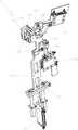
图2是本发明剪刀叉装置的立体图之一,图中处于定位状态;Fig. 2 is one of perspective views of the scissors and fork device of the present invention, in the positioning state among the figure;

图3是本发明剪刀叉装置的立体图之二,图中处于避让状态;Fig. 3 is the second perspective view of the scissors and fork device of the present invention, which is in an avoidance state in the figure;

图4是本发明剪刀叉装置定位板件的状态图;Fig. 4 is a state diagram of the positioning plate of the scissors and fork device of the present invention;

图5是本发明第一勾销缸机构的夹紧状态图,图中隐藏了第一定位销的前部分;Fig. 5 is a clamping state view of the first detent cylinder mechanism of the present invention, in which the front part of the first positioning pin is hidden;

图6是本发明第一勾销缸机构的松开状态图,图中隐藏了第一定位销的前部分;Fig. 6 is a view of the unclamped state of the first detent cylinder mechanism of the present invention, in which the front part of the first positioning pin is hidden;

图7是本发明第一勾销缸机构的立体图;Fig. 7 is a perspective view of the first cancellation cylinder mechanism of the present invention;

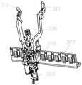
图8是本发明第一定位装置的立体图;Fig. 8 is a perspective view of the first positioning device of the present invention;

图9是本发明第一定位装置定位板件的状态图;Fig. 9 is a state diagram of the positioning plate of the first positioning device of the present invention;

图10是本发明第三定位装置立体图之一;Fig. 10 is one of the perspective views of the third positioning device of the present invention;

图11是本发明第三定位装置立体图之二;Fig. 11 is the second perspective view of the third positioning device of the present invention;

图12是本发明第三定位装置定位板件的状态图之一;Fig. 12 is one of the state diagrams of the positioning plate of the third positioning device of the present invention;

图13是本发明第三定位装置定位板件的状态图之二;Fig. 13 is the second state diagram of the positioning plate of the third positioning device of the present invention;

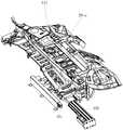
图14是本发明a型前围板总成的分解图;Fig. 14 is an exploded view of the a-type dash panel assembly of the present invention;

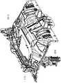
图15是本发明b型前围板总成的分解图;Fig. 15 is an exploded view of the b-type dash panel assembly of the present invention;

图16是本发明下压装置的立体图之一;Figure 16 is one of the perspective views of the pressing device of the present invention;

图17是本发明下压装置的立体图之二;Fig. 17 is the second perspective view of the pressing device of the present invention;

图18是本发明下压装置的立体图之三,图中第二旋转机构旋转至竖直状态;Fig. 18 is the third perspective view of the pressing device of the present invention, in which the second rotating mechanism rotates to a vertical state;

图19是本发明第二定位机构B夹紧状态下的立体图;Fig. 19 is a perspective view of the clamping state of the second positioning mechanism B of the present invention;

图20是本发明第二定位机构B张开状态下的立体图;Fig. 20 is a perspective view of the second positioning mechanism B in the opened state of the present invention;

图21是本发明第二旋转上托机构B和第四旋转上托机构A的状态图之一,图中第二旋转上托机构B处于托住板件的状态,第四旋转上托机构A处于避让状态;Fig. 21 is one of the state diagrams of the second rotating lifting mechanism B and the fourth rotating lifting mechanism A of the present invention. In the figure, the second rotating lifting mechanism B is in the state of supporting the plate, and the fourth rotating lifting mechanism A in avoidance state;

图22是本发明第二旋转上托机构B和第四旋转上托机构A的状态图之二,图中第四旋转上托机构A处于托住板件的状态,第二旋转上托机构B处于避让状态;Fig. 22 is the second state diagram of the second rotating lifting mechanism B and the fourth rotating lifting mechanism A of the present invention, in which the fourth rotating lifting mechanism A is in the state of supporting the plate, and the second rotating lifting mechanism B in avoidance state;

图23是本发明第二定位装置的状态图之一,图中的状态能够夹住a型前围板总成,图中隐藏了第二定位机构B;Fig. 23 is one of the state diagrams of the second positioning device of the present invention, the state in the figure can clamp the a-type dash panel assembly, and the second positioning mechanism B is hidden in the figure;

图24是本发明第二定位装置的状态图之二,图中的状态能够夹住b型前围板总成;Fig. 24 is the second state diagram of the second positioning device of the present invention, the state in the figure can clamp the b-type dash panel assembly;

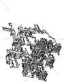
图25是本发明完整的第二定位装置的状态图之三;Fig. 25 is the third state diagram of the complete second positioning device of the present invention;

图26是本发明第二定位装置定位a型前围板总成的状态图。Fig. 26 is a state view of positioning the a-type dash panel assembly by the second positioning device of the present invention.

图中:1为剪刀叉装置;101为第一滑轨;102为第一气缸;103为第一滑动板;104为第一铰接点;105为第二铰接点;106为第二气缸;107为第一旋转板;108为第一公限位块;109为第一母限位块;110为第三气缸;111为定位勾;112为第一定位销;113为第一限位孔;114为固定销;115为环形台阶;116为安装板;117为第四固定架;Among the figure: 1 is a scissors and fork device; 101 is the first slide rail; 102 is the first cylinder; 103 is the first slide plate; 104 is the first hinge point; 105 is the second hinge point; 106 is the second cylinder; 107 108 is the first public spacer block; 109 is the first female spacer block; 110 is the third cylinder; 111 is a positioning hook; 112 is the first positioning pin; 113 is the first spacer hole; 114 is a fixed pin; 115 is an annular step; 116 is a mounting plate; 117 is a fourth fixed frame;

2为第一定位装置;201为第一固定架;202为第二滑轨;203为第二滑动板;204为第四气缸;205为第十三气缸;206为第二旋转板;207为第三铰接点;208为第五气缸;209为第一固定板;210为第一固定块;211为第二定位销;212为第一定位块;213为第一板件感应器;214为第五固定架;2 is the first positioning device; 201 is the first fixed mount; 202 is the second slide rail; 203 is the second sliding plate; 204 is the fourth cylinder; 205 is the thirteenth cylinder; 206 is the second rotating plate; 207 is The third hinge point; 208 is the fifth cylinder; 209 is the first fixed plate; 210 is the first fixed block; 211 is the second positioning pin; 212 is the first positioning block; 213 is the first plate inductor; 214 is fifth fixed frame;

3为第二定位装置;301为第二固定架;302为第四铰接点;303为旋转架;304为第六气缸;305为吊架;306为托板;307为第二下压块B;308为第四下压块A;309为第一下压块B;310为第三下压块1A;311为第三下压块2A;312为第一上托块B;313为第二上托块B;314为第三上托块1A;315为第三上托块2A;316为第四上托块A;317为第十四气缸;318为第二固定板;319为第十六气缸;320为第十四旋转板;321为第三固定板;322为第七气缸;323为第十九气缸;324为第一升降气缸;325为第五固定板;326为第一支撑板;327为第十固定架;328为第十一固定板;329为第十七气缸;330为第十三旋转板;331为第十一固定架;332为第十八气缸;333为第十二固定板;334为第二勾销缸机构;3 is the second positioning device; 301 is the second fixed frame; 302 is the fourth hinge point; 303 is the rotating frame; 304 is the sixth cylinder; 305 is the hanger; 306 is the supporting plate; 307 is the secondpressing block B 308 is the fourth lower pressing block A; 309 is the first lower pressing block B; 310 is the third lower pressing block 1A; 311 is the third lower pressing block 2A; 312 is the first upper bracket B; 313 is the second Upper bracket B; 314 is the third upper bracket 1A; 315 is the third upper bracket 2A; 316 is the fourth upper bracket A; 317 is the fourteenth cylinder; 318 is the second fixed plate; 319 is the tenth Six cylinders; 320 is the fourteenth rotating plate; 321 is the third fixed plate; 322 is the seventh cylinder; 323 is the nineteenth cylinder; 324 is the first lifting cylinder; 325 is the fifth fixed plate; 326 is thefirst support 327 is the tenth fixed frame; 328 is the eleventh fixed plate; 329 is the seventeenth cylinder; 330 is the thirteenth rotating plate; 331 is the eleventh fixed frame; 332 is the eighteenth cylinder; 333 is the first Twelve fixed plates; 334 is the second cancellation cylinder mechanism;

4为第三定位装置;401为第三固定架;402为第三滑轨;403为第三滑动板;404为第九气缸;405为第五铰接点;406为第三旋转板;407为第十气缸;408为第四旋转板;409为第五定位块;411为第三定位销;412为第二公限位块;413为第三公限位块;414为第二母限位块;415为第三母限位块;5为第一上托机构A;4 is the third positioning device; 401 is the third fixed mount; 402 is the third slide rail; 403 is the third sliding plate; 404 is the ninth cylinder; 405 is the fifth hinge point; 406 is the third rotating plate; 407 is The tenth cylinder; 408 is the fourth rotating plate; 409 is the fifth positioning block; 411 is the third positioning pin; 412 is the second public limit block; 413 is the third public limit block; 414 is the second female limit block Block; 415 is the third female limit block; 5 is the first upper support mechanism A;

6为第二定位机构B;601为第二升降气缸;602为第七固定板;603为第二支撑板;604为第二十气缸;605为第八铰接点;606为第八旋转板;607为第十五气缸;608为第九铰接点;609为第一连接板;610为第九旋转板;611为第一下定位块;612为第一上定位块;613为第二下定位块;614为第二上定位块;6 is the second positioning mechanism B; 601 is the second lifting cylinder; 602 is the seventh fixed plate; 603 is the second support plate; 604 is the twentieth cylinder; 605 is the eighth hinge point; 606 is the eighth rotating plate; 607 is the fifteenth cylinder; 608 is the ninth hinge point; 609 is the first connecting plate; 610 is the ninth rotating plate; 611 is the first lower positioning block; 612 is the first upper positioning block; 613 is the second lower positioning block; 614 is the second upper positioning block;

7为第一焊接台;8为第一焊接机器人;10为第二搬运机器人;11为前围上板;12为前围下板;13为第一输入积放链;14为第二输入积放链;15为第一固定焊枪位;16为第一中转台;17为螺柱焊接位;18为旋转台;19为第三搬运机器人;20为第二焊接机器人;21为第三焊接机器人;22为第二固定焊枪位;23为第二中转台;24为第四搬运机器人;25为第五搬运机器人;26为检查台;27为前围上盖板;28-a为a型前围板总成;28-b为b型前围板总成;29为输出积放链;33为第六固定架。7 is the first welding station; 8 is the first welding robot; 10 is the second handling robot; 11 is the upper panel of the cowl; 12 is the lower panel of the cowl; 13 is the first input storage chain; 14 is thesecond input product 15 is the first fixed welding torch position; 16 is the first turntable; 17 is the stud welding position; 18 is the rotary table; 19 is the third handling robot; 20 is the second welding robot; 21 is the third welding robot ; 22 is the second fixed welding torch position; 23 is the second transfer platform; 24 is the fourth transport robot; 25 is the fifth transport robot; 26 is the inspection platform; Coaming board assembly; 28-b is the b-type dash board assembly; 29 is the output accumulation chain; 33 is the sixth fixed mount.

具体实施方式Detailed ways

下面结合附图对本发明技术特征作进一步详细说明以便于所述领域技术人员能够理解。The technical features of the present invention will be described in further detail below in conjunction with the accompanying drawings so that those skilled in the art can understand.

一种汽车前围板自动化焊接线,如图1至图26所示,包括有:An automatic welding line for an automobile dash panel, as shown in Fig. 1 to Fig. 26, comprising:

第一输入积放链13:用于输送前围下板12;The first input accumulating chain 13: used for conveying the cowllower panel 12;

第二输入积放链14:用于输送前围上板11;The second input accumulation chain 14: used for conveying the cowlupper panel 11;

第一搬运机器人9:用于分别搬运前围下板12和前围上板11;The first transport robot 9: used to transport the cowllower panel 12 and the cowlupper panel 11 respectively;

第一焊接台7:用于承载第一搬运机器人9搬运过来的前围下板12和前围上板11;The first welding station 7: used to carry the cowllower panel 12 and the cowlupper panel 11 transported by thefirst handling robot 9;

第一焊接机器人8:用于在第一焊接台7上将前围下板12和前围上板11焊接成前围下板组件;The first welding robot 8: for welding the cowllower panel 12 and the cowlupper panel 11 on thefirst welding station 7 to form the cowl lower panel assembly;

第一固定焊枪位15:用于第二次焊接从第一焊接台7转运过来的前围下板组件;The first fixed welding torch position 15: used for the second welding of the cowl lower plate assembly transferred from thefirst welding station 7;

第一中转台16:用于转运从第一固定焊枪位15搬运过来的前围下板组件;The first transfer platform 16: used to transfer the cowl lower panel assembly transported from the first fixedwelding torch position 15;

第二搬运机器人10:用于搬运第一焊接台7或第一固定焊枪位15上的板件;The second handling robot 10: used to transport the plate on thefirst welding station 7 or the first fixedwelding torch position 15;

螺柱焊接位17:用于第三次焊接从第一中转台16搬运过来的前围下板组件;Stud welding position 17: used for the third welding of the cowl lower plate assembly transported from the first transfer table 16;

第三搬运机器人19:用于将第一中转台16上的前围下板组件搬运至螺柱焊接位17,或者将螺柱焊接位17上的前围下板组件搬运至旋转台18;The third transport robot 19: used to transport the cowl lower panel assembly on thefirst transfer platform 16 to thestud welding position 17, or transport the cowl lower panel assembly on thestud welding position 17 to the rotary table 18;

旋转台18:能360度水平转动、用于承载螺柱焊接位17转运过来的前围下板组件与前围上盖板27,旋转台18的旋转结构为现有技术;Rotary table 18: can rotate 360 degrees horizontally, and is used to carry the cowl lower plate assembly and the cowlupper cover plate 27 transferred from thestud welding position 17. The rotating structure of the rotary table 18 is the prior art;

第二焊接机器人20:设在旋转台18的外端两侧用于将前围下板组件与人工上件的前围上盖板27的一面焊接形成前围板总成,第二焊接机器人20设有两台,分别设在旋转台18外端的两侧;The second welding robot 20: set on both sides of the outer end of the rotary table 18, is used to weld the cowl lower panel assembly and one side of the cowlupper cover plate 27 of the manual upper part to form a cowl assembly. Thesecond welding robot 20 There are two sets, respectively located on both sides of the outer end of the rotary table 18;

第三焊接机器人21:设在旋转台18的内端两侧待旋转台18旋转回来时将前围下板组件与前围上盖板27连接的另一面焊接,即对前围板总成二次焊接,前围下板组件与前围上盖板27连接的两面需要两台焊接机器人分别焊接,第三焊接机器人21也设有两台,分别设在旋转台18内端的两侧;The third welding robot 21: be located at the inner end both sides of theturntable 18 and wait for theturntable 18 to rotate back when theturntable 18 rotates back to weld the other side of the front wall lower panel assembly and the front wallupper cover plate 27, that is, to weld the two sides of the front wall assembly. For the second welding, two welding robots are required to weld the two sides of the cowl lower panel assembly and the cowlupper cover 27 respectively, and thethird welding robot 21 is also provided with two, which are respectively arranged on both sides of the inner end of the rotary table 18;

第二固定焊枪位22:用于将旋转台18转运过来的前围板总成进行第三次焊接;The second fixed welding torch position 22: used for the third welding of the dash panel assembly transferred from the rotary table 18;

第二中转台23:用于接收从第二固定焊枪位22转运过来的前围板总成;The second transfer platform 23: used to receive the dash panel assembly transferred from the second fixedwelding torch position 22;

第四搬运机器人24:用于将第二固定焊枪位22上的前围板总成搬运到第二中转台23上;The fourth transport robot 24: used to transport the dash panel assembly on the second fixedwelding torch position 22 to thesecond transfer platform 23;

检查台26:用于接收从第二中转台23转运过来的前围板总成并进行人工检查;Inspection platform 26: used to receive the dashboard assembly transferred from thesecond transfer platform 23 and perform manual inspection;

第五搬运机器人25:用于将第二中转台23上的前围板总成搬运至检查台26,然后将检查台26上的前围板总成搬运至输出积放链29,或者直接将第二中转台23上的前围板总成搬运至输出积放链29;The fifth transport robot 25: used to transport the cowl assembly on thesecond transfer platform 23 to theinspection platform 26, and then transport the cowl assembly on theinspection platform 26 to theoutput accumulation chain 29, or directly The dash panel assembly on thesecond transfer platform 23 is transported to theoutput accumulating chain 29;

输出积放链29:用于将焊接好的前围板总成输送至下一工序。Output accumulation chain 29: used to transport the welded dash panel assembly to the next process.

该汽车前围板自动化焊接线设备众多,而搬运机器人的作业半径有限,为确保安全、高效工作,避免出现干涉,在第一固定焊枪位15和螺柱焊接位17之间设置第一中转台16;在第二固定焊枪位22和检查台26之间设置第二中转台23,第一中转台16和第二中转台23结构相同,上述没有描写具体结构的设备均为现有技术。There are many equipments in the automatic welding line for the front panel of the automobile, and the operating radius of the handling robot is limited. In order to ensure safe and efficient work and avoid interference, a first transfer table is set between the first fixedwelding torch position 15 and thestud welding position 17 16. Asecond transfer platform 23 is set between the second fixedwelding torch position 22 and theinspection platform 26. Thefirst transfer platform 16 and thesecond transfer platform 23 have the same structure, and the above-mentioned devices without specific structures are all prior art.

本专利申请汽车前围板自动化焊接线适配多种车型的前围板总成,现举例两种:a型前围板总成28-a和b型前围板总成28-b,如图14和图15所示。The automatic welding line of the automobile dash panel of this patent application is adapted to the dash panel assembly of various vehicle types, and two examples are given now: a-type dash panel assembly 28-a and b-type dash panel assembly 28-b, such as Figure 14 and Figure 15.

本专利申请还请求保护一种汽车前围板自动化焊接线焊接的方法,包括有:通过第一输入积放链13输送上一工序焊接的前围下板12,人工往第二输入积放链14放入前围上板11,通过第一搬运机器人9分别将一块前围下板12和一块前围上板11搬运至第一焊接台7,通过第一焊接机器人8将第一焊接台7上的一块前围下板12和一块前围上板11一次焊接形成前围下板组件,第二搬运机器人10将前围下板组件转运至第一固定焊枪位15进行第二次焊接,第二搬运机器人10将二次焊接后的前围下板组件转运至第一中转台16,第三搬运机器人19将第一中转台16上的前围下板组件搬运至螺柱焊接位17进行第三次焊接;This patent application also claims to protect a method for automatic welding line welding of automobile cowl panels, including: transporting the cowllower panel 12 welded in the previous process through the firstinput accumulation chain 13, and manually feeding to the secondinput accumulation chain 13. 14 into the cowlupper panel 11, a cowllower panel 12 and a cowlupper panel 11 are respectively transported to thefirst welding station 7 by thefirst transport robot 9, and thefirst welding station 7 is transported by the first welding robot 8 A cowllower panel 12 and a cowlupper panel 11 are welded once to form the cowl lower panel assembly, and thesecond handling robot 10 transfers the cowl lower panel assembly to the first fixedwelding torch position 15 for the second welding. Thesecond transfer robot 10 transfers the cowl lower panel assembly after secondary welding to the first transfer table 16, and thethird transfer robot 19 transfers the cowl lower panel assembly on the first transfer table 16 to thestud welding position 17 for the second transfer. Three welding;

第三搬运机器人19将三次焊接后的前围下板组件搬运至旋转台18的内端,旋转台18水平旋转180度将内端的前围下板组件旋转至外端与人工上料的前围上盖板27通过两台第二焊接机器人20进行第四次焊接形成前围板总成,也是前围板总成的第一次焊接,此时焊接的是前围下板组件与前围上盖板27连接的其中一面,然后旋转台18旋转180度转回内端,两台第三焊接机器人21对前围板总成进行第二次焊接,此时焊接的是前围下板组件与前围上盖板27连接的另一面;Thethird handling robot 19 transports the cowl lower panel assembly welded three times to the inner end of the rotary table 18, and the rotary table 18 horizontally rotates 180 degrees to rotate the inner cowl lower panel assembly to the outer end and manually load the cowl assembly. Theupper cover plate 27 is welded for the fourth time by twosecond welding robots 20 to form the dash panel assembly, which is also the first welding of the dash panel assembly. At this time, the dash lower panel assembly and the dash upper panel are welded One side of thecover plate 27 is connected, and then the rotary table 18 is rotated 180 degrees to turn back to the inner end, and the twothird welding robots 21 perform the second welding on the dash panel assembly. The other side connected to thecowl top cover 27;

第四搬运机器人24将旋转台18上二次焊接的前围板总成搬运至第二固定焊枪位22进行第三次焊接,第四搬运机器人24将三次焊接后的前围板总成搬运至第二中转台23;第五搬运机器人25将第二中转台23上的前围板总成搬运至检查台26人工检查,质量符合要求的由第五搬运机器人25搬运至输出积放链29,通过输出积放链29输送至下一工序,其中的人工检查为抽检,没抽中的话,通过第五搬运机器人25直接将第二中转台23上的前围板总成搬运至输出积放链29。Thefourth transport robot 24 transports the dash panel assembly welded for the second time on the rotary table 18 to the second fixedwelding torch position 22 for the third welding, and thefourth transport robot 24 transports the dash panel assembly welded three times to Thesecond transfer platform 23; thefifth transport robot 25 transports the dash panel assembly on thesecond transfer platform 23 to the inspection table 26 for manual inspection, and thefifth transport robot 25 transports the products that meet the requirements to theoutput accumulation chain 29, It is transported to the next process through theoutput accumulation chain 29, and the manual inspection is random inspection. If it is not selected, the dash panel assembly on thesecond transfer platform 23 is directly transported to the output accumulation chain by thefifth transfer robot 25. 29.

如图2至图7所示,在所述第二搬运机器人10的抓手上设有用于定位板件的剪刀叉装置1,所述剪刀叉装置1包括第一滑动机构、被第一滑动机构驱动滑动的第一旋转机构、被第一旋转机构驱动转动的第一勾销缸机构。As shown in Figures 2 to 7, a scissor-fork device 1 for positioning a plate is provided on the gripper of thesecond transport robot 10, and the scissor-fork device 1 includes a first sliding mechanism, a first sliding mechanism The first rotating mechanism that drives sliding, and the first detent cylinder mechanism that is driven to rotate by the first rotating mechanism.

所述第一滑动机构包括第一滑轨101、被第一气缸102驱动能沿第一滑轨101滑动的第一滑动板103,在所述第一滑动板103上设有多个安装板116。第一旋转机构被第一滑动机构沿第一滑轨101上滑动,第一旋转机构只占用了其中一个安装板116,其他安装板116预留用于安装其他机构用于定位其他车型板件,因此可以适配多种车型板件。因为不同车型板件需要用第一勾销缸机构定位的孔的位置不同,故设置第一滑动机构来移动第一勾销缸机构。所述第一滑动机构除了第一气缸102驱动外也可以用丝杠机构代替。The first sliding mechanism includes a first slidingrail 101, a first slidingplate 103 driven by afirst cylinder 102 to slide along the first slidingrail 101, and a plurality of mountingplates 116 are arranged on the first slidingplate 103 . The first rotating mechanism is slid along thefirst slide rail 101 by the first sliding mechanism, and the first rotating mechanism only occupies one of the mountingplates 116, and the other mountingplates 116 are reserved for installing other mechanisms for positioning other vehicle models. Therefore, it can be adapted to a variety of vehicle models. Because the positions of the holes that need to be positioned by the first detent cylinder mechanism are different for different vehicle models, the first slide mechanism is set to move the first detent cylinder mechanism. In addition to being driven by thefirst cylinder 102, the first sliding mechanism can also be replaced by a screw mechanism.

所述第一旋转机构包括固定在其中一个安装板116上的第四固定架117,在第四固定架117上分别设有第一铰接点104和第二铰接点105,在第四固定架117上还设有能绕第一铰接点104转动的第二气缸106、被第二气缸106驱动能绕第二铰接点105转动的第一旋转板107,在第四固定架117上设有第一公限位块108,在第一旋转板107上设有与第一公限位块108对应的第一母限位块109。在第一旋转板107旋转到竖直方向时,第一母限位块109会撞到第一公限位块108。下文中的旋转机构也都是用公母限位块碰撞的方式来进行限位。Described first rotating mechanism comprises the 4thfixed mount 117 that is fixed on wherein one mountingplate 116, is respectively provided withfirst hinge point 104 and thesecond hinge point 105 on the 4thfixed mount 117, on the 4thfixed mount 117 There is also asecond cylinder 106 that can rotate around thefirst hinge point 104, a firstrotating plate 107 driven by thesecond cylinder 106 that can rotate around thesecond hinge point 105, and the fourth fixedframe 117 is provided with a first Themale limiting block 108 is provided with a firstfemale limiting block 109 corresponding to the firstmale limiting block 108 on the firstrotating plate 107 . When the firstrotating plate 107 rotates to the vertical direction, the firstfemale limiting block 109 will collide with the firstmale limiting block 108 . The rotary mechanism below is also limited by the collision of the male and female limit blocks.

设置第一旋转板107的目的是:因为该剪刀叉装置1要适配多车型板件,不同板件的形状会相差很大,需要用第一勾销缸机构定位的孔的高度也不同,虽然竖直状态下的第一旋转板107沿第一滑轨101滑过去不会撞到本实施例a型前围板总成28-a,但不能保证换成另外一种板件也不会撞到,所以为了避让板件,设置一个能够旋转的第一旋转板107,第一旋转机构滑动到待定位的板件正下方时,才将第一旋转板107旋转至竖直状态。The purpose of arranging the firstrotating plate 107 is: because the scissors and fork device 1 is to be adapted to multi-vehicle panels, the shapes of different panels will vary greatly, and the heights of the holes that need to be positioned by the first detent cylinder mechanism are also different. The firstrotating plate 107 in the vertical state slides along thefirst slide rail 101 and will not hit the a-type dash panel assembly 28-a of this embodiment, but it cannot be guaranteed that it will not hit when it is replaced by another plate. Therefore, in order to avoid the plate, a rotatable firstrotating plate 107 is provided. When the first rotating mechanism slides directly below the plate to be positioned, the firstrotating plate 107 is rotated to a vertical state.

如图5至图7所示,所述第一勾销缸机构包括设在第一旋转板107上的第三气缸110,在第一旋转板107上且位于第三气缸110的上方设有第一定位销112,所述第一定位销112由两块板通过固定销114连接组成,第一定位销112的顶部呈锥形,组成第一定位销112的两块板之间设有两个对称、且能被第三气缸110驱动升降的定位勾111,第三气缸110的活塞杆与两定位勾111的底端铰接,在定位勾111上设有第一限位孔113,所述固定销114从两个定位勾111的第一限位孔113穿过,所述第一限位孔113包括竖直的上部孔和沿内侧倾斜的下部孔,上部孔和下部孔连通,在第一定位销112的锥形顶部外侧设有环形台阶115,被驱动下降的定位勾111夹于所述环形台阶115上。As shown in FIGS. 5 to 7 , the first detent cylinder mechanism includes athird air cylinder 110 arranged on the firstrotating plate 107 , and afirst cylinder 110 is arranged on the firstrotating plate 107 above thethird air cylinder 110 . Locatingpin 112, described first locatingpin 112 is made up of two plates connected by fixingpin 114, and the top offirst locating pin 112 is conical, is provided with two symmetry between two plates that form first locatingpin 112. , and can be driven by thethird cylinder 110 to lift thepositioning hook 111, the piston rod of thethird cylinder 110 is hinged with the bottom ends of the two positioning hooks 111, and thepositioning hook 111 is provided with afirst limit hole 113, and the fixedpin 114 passes through the first limitingholes 113 of the two positioning hooks 111. The first limitingholes 113 include a vertical upper hole and a lower hole inclined along the inner side. The upper hole and the lower hole are connected. In the first positioning Anannular step 115 is provided outside the tapered top of thepin 112 , and thepositioning hook 111 driven to descend is clamped on theannular step 115 .

因此,剪刀叉装置1设置多个用于安装其他机构的安装板116、用于移动第一勾销缸机构的第一滑动机构、用于避让的第一旋转机构,均是为了适配更多车型板件。Therefore, the scissors and fork device 1 is provided with a plurality of mountingplates 116 for installing other mechanisms, a first sliding mechanism for moving the first detent cylinder mechanism, and a first rotating mechanism for avoidance, all in order to adapt to more vehicle models. plate.

两个定位勾111对称设置,第三气缸110驱动定位勾111上升时,如图6所示,两个定位勾111也向内收缩在一起,此时只是第一定位销112对板件起到定位作用,即向上托住板件,定位勾111不能夹紧板件。第三气缸110驱动定位勾11下降时,如图5所示,第一限位孔113沿固定销114下移,定位勾111向外侧展开将板件下压于环形台阶115上。The two positioning hooks 111 are arranged symmetrically. When thethird cylinder 110 drives the positioning hooks 111 to rise, as shown in Figure 6, the two positioning hooks 111 also shrink together inwardly. The positioning function is to support the plate upwards, and thepositioning hook 111 cannot clamp the plate. When thethird cylinder 110 drives thepositioning hook 11 to descend, as shown in FIG.

剪刀叉装置1的工作方法和原理如下:首先通过第一气缸102驱动第一滑动板103沿第一滑轨101滑动至指定的位置,然后第二气缸106驱动第一旋转板107绕第二铰接点105逆时针旋转,将第一定位销112旋转升起,直到第一母限位块109碰到第一公限位块108,第一定位销112就处于竖直状态,也刚好插入板件中要定位的孔内,环形台阶115托住板件的底面,最后第三气缸110驱动定位勾111下降,定位勾向外侧展开下压将板件夹于环形台阶115上;松开板件的步骤与夹紧板件的步骤顺序相反。The working method and principle of the scissor-fork device 1 are as follows: first, the first slidingplate 103 is driven to slide to a designated position along thefirst slide rail 101 by thefirst air cylinder 102, and then thesecond air cylinder 106 drives the firstrotating plate 107 around the second hinge Rotate thepoint 105 counterclockwise, rotate and raise thefirst positioning pin 112 until the firstfemale stopper 109 touches the firstmale stopper 108, thefirst positioning pin 112 is in a vertical state and just inserted into the plate In the hole to be positioned, theannular step 115 supports the bottom surface of the plate, and finally thethird cylinder 110 drives thepositioning hook 111 to descend, and the positioning hook expands to the outside and presses down to clamp the plate on theannular step 115; loosen the position of the plate The steps are reversed to those for clamping the panels.

在所述第一焊接台7上设有对板件定位的第一定位装置2,如图8和图9所示,第一焊接台7接收第一搬运机器人9搬运过来的板件后,第一搬运机器人9就会有信号反馈给第一定位装置2,第一定位装置2自动开始动作定位好板件。Thefirst positioning device 2 for positioning the plate is provided on thefirst welding station 7, as shown in Figure 8 and Figure 9, after thefirst welding station 7 receives the plate carried by thefirst transport robot 9, the second Once therobot 9 is transported, a signal will be fed back to thefirst positioning device 2, and thefirst positioning device 2 will automatically start to move and position the plate.

所述第一定位装置2包括第一固定架201,在第一固定架201上设有第二滑轨202、能沿第二滑轨202滑动的第二滑动板203、驱动第二滑动板203上下滑动的第四气缸204,在第二滑动板203上设有下安装位和上安装位,在所述下安装位上分别设有第五固定架214和第五气缸208,在第五固定架214上分别设有第三铰接点207、被第五气缸208驱动绕第三铰接点207转动的第二旋转板206,在所述第二旋转板206上分别设有第十三气缸205以及由第十三气缸205驱动升降的第一固定板209,在第一固定板209的侧面固定连接有第一固定块210,在第一固定块210上设有能够从板件上的孔穿出从而对板件定位的第二定位销211;在第二旋转板206上还设有分别对板件侧向定位的第一定位块212、第一板件感应器213。Thefirst positioning device 2 includes a firstfixed mount 201, on which asecond slide rail 202, asecond slide plate 203 capable of sliding along thesecond slide rail 202, and asecond slide plate 203 driven Thefourth cylinder 204 that slides up and down is provided with a lower installation position and an upper installation position on thesecond slide plate 203, and a fifth fixedframe 214 and afifth cylinder 208 are respectively provided on the lower installation position, and the fifth fixedframe 214 and thefifth cylinder 208 are respectively arranged on the second slidingplate 203. Theframe 214 is respectively provided with athird hinge point 207, a secondrotating plate 206 driven by thefifth cylinder 208 to rotate around thethird hinge point 207, and athirteenth cylinder 205 and The first fixedplate 209 driven up and down by thethirteenth cylinder 205 is fixedly connected with the firstfixed block 210 on the side of the first fixedplate 209. Thereby, thesecond positioning pin 211 for positioning the plate; thefirst positioning block 212 and thefirst plate sensor 213 for laterally positioning the plate are also provided on the secondrotating plate 206 .

图9中的板件为a型前围板总成28-a,第五固定架214通过螺丝固定在第二滑动板203的下安装位上,上安装位上也设有用于固定其他夹紧单元的螺丝孔,使得该第一定位装置2能够适配多种车型板件。The panel in Fig. 9 is a-type dash panel assembly 28-a, and thefifth fixing frame 214 is fixed on the lower mounting position of thesecond slide plate 203 by screws, and the upper mounting position is also provided with other clamping brackets for fixing. The screw holes of the unit make thefirst positioning device 2 adaptable to panels of various vehicle types.

第四气缸204驱动第二滑动板203升降的高度可以通过公母限位块的配合来实现。第一板件感应器213为接近开关,当定位好板件后,第一板件感应器213就能感应到板件并且给焊接装置发送信号,以自动开始板件的焊接工作。The height to which thefourth cylinder 204 drives the second slidingplate 203 to rise and fall can be realized through the cooperation of the male and female limit blocks. Thefirst panel sensor 213 is a proximity switch. When the panel is positioned, thefirst panel sensor 213 can sense the panel and send a signal to the welding device to automatically start the welding of the panel.

第一定位装置2的工作方法和原理:首先第四气缸204驱动第二滑动板203上升至指定的高度,然后第五气缸208驱动第二旋转板206转动靠近板件,最后第十三气缸205驱动第一固定板209上升,第一固定板209带动第二定位销211和第一定位块212运动,第二定位销211插入板件中要定位的孔内,第一定位块212也从侧面对板件进行定位;松开板件的步骤与夹紧板件的步骤顺序相反。The working method and principle of the first positioning device 2: first thefourth cylinder 204 drives the second slidingplate 203 to rise to a specified height, then thefifth cylinder 208 drives the secondrotating plate 206 to rotate close to the plate, and finally thethirteenth cylinder 205 Drive the first fixedplate 209 to rise, the first fixedplate 209 drives thesecond positioning pin 211 and thefirst positioning block 212 to move, thesecond positioning pin 211 is inserted in the hole to be positioned in the plate, and thefirst positioning block 212 also moves from the side Positioning the panel; the sequence of steps for unclamping the panel is the reverse of that for clamping the panel.

如图10至图13所示,在所述第一搬运机器人9的抓手上设有能对两种板件定位的第三定位装置4,所述第三定位装置4包括第三固定架401,在第三固定架401上设有第三滑轨402、能沿第三滑轨402上下滑动的第三滑动板403、驱动第三滑动板403滑动的第九气缸404,在第三滑动板403上设有第五铰接点405、能绕第五铰接点405旋转的第三旋转板406、用于驱动第三旋转板406转动的第十气缸407,在第三旋转板406上固定连接有第四旋转板408,在第三旋转板406的外端设有在第十气缸407的活塞杆缩回时对所述板件的底面定位的第五定位块409,在第四旋转板408的外端设有在第十气缸407的活塞杆伸出时对另一种板件定位的第三定位销411。As shown in Figures 10 to 13, athird positioning device 4 capable of positioning two types of panels is provided on the gripper of thefirst handling robot 9, and thethird positioning device 4 includes athird fixing frame 401 , athird slide rail 402, athird slide plate 403 that can slide up and down along thethird slide rail 402, aninth cylinder 404 that drives thethird slide plate 403 to slide are provided on the thirdfixed frame 401, and thethird slide plate 403 is provided with afifth hinge point 405, a thirdrotating plate 406 capable of rotating around thefifth hinge point 405, and atenth cylinder 407 for driving the thirdrotating plate 406 to rotate. The thirdrotating plate 406 is fixedly connected with The fourthrotating plate 408 is provided with afifth positioning block 409 positioned on the bottom surface of the plate when the piston rod of thetenth cylinder 407 is retracted at the outer end of the thirdrotating plate 406. The outer end is provided with athird positioning pin 411 for positioning another plate when the piston rod of thetenth cylinder 407 is stretched out.

在第三滑动板403上且位于第五铰接点405的两侧分别设有第二公限位块412和第三公限位块413,在第三旋转板406的两侧对应设有与第二公限位块412配合的第二母限位块414、与第三公限位块413配合的第三母限位块415。第九气缸404用于调节第五定位块409和第三定位销411的高度,可定位不同高度的板件,也可用于避让。On the third slidingplate 403 and on both sides of thefifth hinge point 405, a secondpublic limiting block 412 and a third public limitingblock 413 are respectively provided. The secondfemale limiting block 414 matched with the secondmale limiting block 412 and the thirdfemale limiting block 415 matched with the thirdmale limiting block 413 . Theninth cylinder 404 is used to adjust the height of thefifth positioning block 409 and thethird positioning pin 411 , which can position boards of different heights, and can also be used for avoidance.

如图11和图13所示,第十气缸407的活塞杆缩回,第三旋转板406和第四旋转板408顺时针转动,当第三母限位块415撞到第三公限位块413时就说明转到了最高位置,第三定位销411转下去以避让板件,第五定位块409转上去至竖直状态,从一种板件的底面进行定位,具体是托住a型前围板总成28-a。As shown in Figure 11 and Figure 13, the piston rod of thetenth cylinder 407 retracts, the thirdrotating plate 406 and the fourthrotating plate 408 rotate clockwise, when the thirdfemale stopper 415 hits the third male stopper When 413, it has been explained that it has turned to the highest position, thethird positioning pin 411 turns down to avoid the plate, thefifth positioning block 409 turns up to the vertical state, and locates from the bottom surface of a kind of plate, specifically supporting the a-type front Shroud assembly 28-a.

如图10和图12所示,第十气缸407的活塞杆升上去,第三旋转板406和第四旋转板408逆时针转动,当第二母限位块414撞到第二公限位块412时就说明转到位了,第五定位块409转下去以避让板件,第三定位销411转上去至竖直状态,插入另一种板件的孔内来定位,具体是定位b型前围板总成28-b。因此第三定位装置4至少可以适用两种车型板件,用途广泛。As shown in Figure 10 and Figure 12, the piston rod of thetenth cylinder 407 rises up, the thirdrotating plate 406 and the fourthrotating plate 408 rotate counterclockwise, when the secondfemale stopper 414 hits the second male stopper When 412, it has been explained that it has turned to the position, thefifth positioning block 409 is turned down to avoid the plate, thethird positioning pin 411 is turned up to the vertical state, and inserted into the hole of another plate for positioning, specifically before positioning the b-type Shroud assembly 28-b. Therefore, thethird positioning device 4 can be applied to at least two types of vehicle panels, and has a wide range of uses.

在所述旋转台18上设有对多种板件定位的第二定位装置3,所述第二定位装置3包括有:下压装置、用于带动第一上托块B312作升降运动的第一上托机构B、用于带动第二上托块B313作旋转运动的第二旋转上托机构B、用于带动第三上托块1A314和第三上托块2A315作升降运动的第三上托机构A、用于带动第四上托块A316作旋转运动的第四旋转上托机构A;下压装置包括用于带动旋转架303转动的第二旋转机构、第二下压机构B、第四下压机构A、第一旋转下压机构B、第三下压机构A,第二下压机构B、第四下压机构A、第一旋转下压机构B、第三下压机构A分别设在第二旋转机构上;Thesecond positioning device 3 for positioning various boards is provided on the rotary table 18. Thesecond positioning device 3 includes: a pressing device, a first lifting device for driving the first upper bracket B312 to move up and down. One upper support mechanism B, the second rotating upper support mechanism B for driving the second upper support block B313 to rotate, the third upper support mechanism B for driving the third upper support block 1A314 and the third upper support block 2A315 for lifting movement Supporting mechanism A, the fourth rotating upper supporting mechanism A for driving the fourth upper supporting block A316 to rotate; the pressing device includes a second rotating mechanism for driving therotating frame 303, a second pressing mechanism B, a The four pressing mechanisms A, the first rotating pressing mechanism B, the third pressing mechanism A, the second pressing mechanism B, the fourth pressing mechanism A, the first rotating pressing mechanism B, and the third pressing mechanism A respectively set on the second rotating mechanism;

为便于区分,这里的机构A表示用于对a型前围板总成28-a定位,机构B用于对b型前围板总成28-b定位。For ease of distinction, the mechanism A here is used to position the a-type dash panel assembly 28-a, and the mechanism B is used to position the b-type dash panel assembly 28-b.

在旋转架303上的左右两侧分别设有吊架305,在吊架305上设有多个安装位,在其中一个安装位设有带动第二下压块B307作升降运动的第二下压机构B,在另一个安装位上设有带动第四下压块A308作升降运动的第四下压机构A;在旋转架303的自由端设有托板306,在所述托板306上设有多个安装位,在其中一个安装位设有带动第一下压块B309转动的第一旋转下压机构B,在另一个安装位上设有带动第三下压块1A310和第三下压块2A311作升降运动的第三下压机构A;Hangers 305 are respectively provided on the left and right sides of theswivel frame 303, and a plurality of mounting positions are provided on thehanger 305, and a second pressing down that drives the second pressing block B307 for lifting movement is provided in one of the mounting positions. Mechanism B is provided with a fourth pressing mechanism A that drives the fourth lower pressing block A308 for lifting movement on another installation position; a supportingplate 306 is provided at the free end of therotating frame 303, and a supportingplate 306 is provided on the supportingplate 306. There are multiple installation positions, and one of the installation positions is provided with a first rotary pressing mechanism B that drives the first pressing block B309 to rotate, and the other installation position is provided with a driving third pressing block 1A310 and a third pressing block B309. Block 2A311 is used as the third pressing mechanism A for lifting movement;

第一上托块B312与第一下压块B309配合将b型前围板总成28-b夹紧;具体是第一上托块B312在b型前围板总成28-b的一处托住,第一下压块B309又在该处下压,实现夹紧,下文同理;The first upper support block B312 cooperates with the first lower pressure block B309 to clamp the b-type dash panel assembly 28-b; specifically, the first upper support block B312 is at a position of the b-type dash panel assembly 28-b Hold it, and the first pressing block B309 presses down there again to realize clamping, the same reason below;

第二上托块B313与第二下压块B307配合将b型前围板总成28-b夹紧;The second upper support block B313 cooperates with the second lower pressing block B307 to clamp the b-type dash panel assembly 28-b;

第三上托块1A314与第三下压块1A310配合、第三上托块2A315与第三下压块2A311配合将a型前围板总成28-a夹紧;The third upper support block 1A314 cooperates with the third lower pressing block 1A310, and the third upper supporting block 2A315 cooperates with the third lower pressing block 2A311 to clamp the a-shaped dash panel assembly 28-a;

第四上托块A316与第四下压块A308配合将a型前围板总成28-a夹紧;The fourth upper support block A316 cooperates with the fourth lower pressing block A308 to clamp the a-type dash panel assembly 28-a;

具体地,所述第二旋转机构包括第二固定架301,在第二固定架301上分别设有第四铰接点302、能绕第四铰接点302旋转的旋转架303、用于驱动旋转架303转动的第六气缸304,旋转架303可以被转动至竖直状态,方便避让,如图18和图25所示;Specifically, the second rotating mechanism includes a second fixedframe 301, on which afourth hinge point 302, arotating frame 303 capable of rotating around thefourth hinge point 302, and a rotating frame for driving the rotating frame are respectively arranged. 303 rotates thesixth cylinder 304, and theswivel frame 303 can be rotated to a vertical state to facilitate avoidance, as shown in Figure 18 and Figure 25;

所述第二下压机构B包括有设在所述吊架305一个安装位上的第七气缸322、由第七气缸322驱动的第二下压块B307,如图16至图18所示;The second pressing mechanism B includes aseventh air cylinder 322 arranged on a mounting position of thehanger 305, and a second pressing block B307 driven by theseventh air cylinder 322, as shown in FIGS. 16 to 18 ;

所述第四下压机构A包括有设在所述吊架305另一个安装位上的第十四气缸317、由第十四气缸317驱动的第四下压块A308,本专利所述第十四气缸317与所述第七气缸322是设在所述吊架305的同一侧,如图16至图18所示;The fourth pressing mechanism A includes afourteenth cylinder 317 located on another installation position of thehanger 305, and a fourth pressing block A308 driven by thefourteenth cylinder 317. The fourcylinders 317 and theseventh cylinder 322 are arranged on the same side of thehanger 305, as shown in FIGS. 16 to 18 ;

所述第一旋转下压机构B包括有固定在所述托板306其中一个安装位上的第二固定板318,在所述第二固定板318上水平设有第十六气缸319,第十六气缸319的活塞杆沿水平方向伸缩,第十六气缸319的活塞杆铰接有第十四旋转板320,在第十四旋转板320的自由端底面设有第一下压块B309,如图16至图18所示;The first rotary pressing mechanism B includes asecond fixing plate 318 fixed on one of the mounting positions of the supportingplate 306, and asixteenth cylinder 319 is horizontally arranged on thesecond fixing plate 318. The piston rod of the sixcylinders 319 expands and contracts in the horizontal direction, the piston rod of thesixteenth cylinder 319 is hinged with the fourteenthrotating plate 320, and the first lower pressing block B309 is arranged on the bottom surface of the free end of the fourteenthrotating plate 320, as shown in the figure 16 to Figure 18;

所述第三下压机构A包括固定在所述托板306另一个安装位上的第三固定板321,在所述第三固定板321上设有第十九气缸323、由第十九气缸323驱动升降的第三下压块1A310和第三下压块2A311,如图16至图18所示;The third depressing mechanism A includes a thirdfixed plate 321 fixed on another mounting position of the supportingplate 306, anineteenth cylinder 323 is arranged on the thirdfixed plate 321, and thenineteenth cylinder 323 drives the third lower pressing block 1A310 and the third lower pressing block 2A311, as shown in Figure 16 to Figure 18;

所述第一上托机构B包括有固定在第六固定架33上的第一升降气缸324、被第一升降气缸324驱动升降的第五固定板325,第五固定板325升降时通过两根导向柱导向;在第五固定板325上固定有第一支撑板326,在第一支撑板326上设有托住b型前围板总成28-b底面的第一上托块B312,当要定位a型前围板总成28-a时,第一升降气缸324驱动第一上托块B312下降避让,如图23所示。The first lifting mechanism B includes afirst lift cylinder 324 fixed on the sixth fixedframe 33, a fifth fixedplate 325 driven up and down by thefirst lift cylinder 324, and the fifth fixedplate 325 passes through two guide column guide; the fifth fixedplate 325 is fixed with thefirst support plate 326, and thefirst support plate 326 is provided with the first upper support block B312 supporting the b-type dash panel assembly 28-b bottom surface, when When positioning the a-type dash panel assembly 28-a, thefirst lift cylinder 324 drives the first upper support block B312 to descend and avoid, as shown in FIG. 23 .

在所述旋转架303的下方设有第十固定架327,在所述第十固定架327上设有多个安装位,所述第二旋转上托机构B设在其中一个安装位上,所述第四旋转上托机构A设在另一个安装位上,所述第二旋转上托机构B包括固定在第十固定架327其中一个安装位上的第十一固定板328,在所述第十一固定板328上铰接有第十七气缸329,第十七气缸329的活塞杆铰接有第十三旋转板330,驱动第十三旋转板330绕第十一固定板328的铰接点转动,在第十三旋转板330的自由端设有用于托住b型前围板总成28-b的第二上托块B313,如图21和图22所示。A tenth fixedframe 327 is provided below therotating frame 303, and a plurality of installation positions are arranged on the tenth fixedframe 327, and the second rotating lifting mechanism B is arranged on one of the installation positions, so that The fourth rotating lifting mechanism A is located at another installation position, and the second rotating lifting mechanism B includes aneleventh fixing plate 328 fixed on one of the tenth fixingbrackets 327. The eleventh fixedplate 328 is hinged with aseventeenth cylinder 329, and the piston rod of theseventeenth cylinder 329 is hinged with a thirteenthrotating plate 330, which drives the thirteenthrotating plate 330 to rotate around the hinge point of the eleventh fixedplate 328, At the free end of the thirteenthrotating plate 330 is provided a second upper bracket B313 for supporting the b-shaped dash panel assembly 28-b, as shown in FIG. 21 and FIG. 22 .

所述第四旋转上托机构A的结构与第二旋转上托机构B的结构相同,如图21和图22所示。The structure of the fourth rotating lifting mechanism A is the same as that of the second rotating lifting mechanism B, as shown in FIG. 21 and FIG. 22 .

在所述第十固定架327的前方设有能被伺服机构驱动左右滑动的第十一固定架331,伺服机构包括伺服电机和丝杠机构,在所述第十一固定架331上设有多个安装位,所述第三上托机构A设在其中一个安装位上,所述第三上托机构A包括有设在第十一固定架331其中一个安装位上的第十八气缸332、被第十八气缸332驱动升降的第十二固定板333,所述的第三上托块1A314和第三上托块2A315设在所述第十二固定板333的顶部。In front of the tenthfixed mount 327, an eleventhfixed mount 331 that can be driven by a servo mechanism to slide left and right is provided. The servo mechanism includes a servo motor and a lead screw mechanism. The third lifting mechanism A is located at one of the installation positions, and the third lifting mechanism A includes aneighteenth air cylinder 332 on one of theeleventh fixing frame 331 installation positions, The twelfth fixedplate 333 is driven up and down by theeighteenth cylinder 332 , and the third upper bracket 1A314 and the third upper bracket 2A315 are arranged on the top of the twelfth fixedplate 333 .

在所述第十二固定板333的侧部设有用于定位a型前围板总成28-a的第二勾销缸机构334,所述第二勾销缸机构334的结构与第一勾销缸机构的结构相同,如图24所示。The side of thetwelfth fixing plate 333 is provided with a seconddetent cylinder mechanism 334 for positioning the a-type dash panel assembly 28-a. The structure is the same, as shown in Figure 24.

所述的第六固定架33至少设有三个,两侧的第六固定架33的一个安装位上都设有一个第一上托机构B,所述的下压装置也对应设有三个,两侧的下压装置与两侧的第一上托机构B配合将b型前围板总成28-b的两侧夹住;在中间的第六固定架33的一个安装位上设有用于托住a型前围板总成28-a的第一上托机构A5,第一上托机构A5与第一上托机构B的结构相同,只是为适配a型前围板总成28-a,第一上托机构A5的支撑板、上托块的形状做的与第一上托机构B的不同,如图25所示,第一上托机构A5与中间的下压装置配合夹住a型前围板总成28-a的中部,当要夹住b型前围板总成28-b时,第一上托机构A5下降避让。The sixth fixedframe 33 is provided with at least three, and a first support mechanism B is provided on a mounting position of the sixth fixedframe 33 on both sides, and the described pressing device is also provided with three correspondingly, two The pressing device on the side cooperates with the first lifting mechanism B on both sides to clamp both sides of the b-type dash panel assembly 28-b; Hold the first lifting mechanism A5 of the a-type dash panel assembly 28-a, the structure of the first lifting mechanism A5 is the same as that of the first lifting mechanism B, only for adapting the a-type dash panel assembly 28-a , the shape of the supporting plate and the upper block of the first lifting mechanism A5 is different from that of the first lifting mechanism B, as shown in Figure 25, the first lifting mechanism A5 cooperates with the pressing device in the middle to clamp a The middle part of type dash panel assembly 28-a, when clamping b type dash panel assembly 28-b, the first support mechanism A5 descends to avoid.

另外,第二定位装置3还包括有第二定位机构B6,当然还可以包括其他机构,限于篇幅的原因就不再一一描述,如图25和图26所示;在中间的第六固定架33的另一个安装位上设有第二定位机构B6,用于夹住b型前围板总成28-b后部翘起的部分,即前围上盖板27,第二定位机构B6包括有固定在第六固定架33上的第二升降气缸601、被第二升降气缸601驱动升降的第七固定板602,第七固定板602升降时通过两根导向柱导向;在第七固定板602上固定有第二支撑板603,在第二支撑板603上分别铰接有第二十气缸604、由第二十气缸604驱动绕第八铰接点605转动的第八旋转板606,在所述第八旋转板606上分别铰接有第十五气缸607、由第十五气缸607驱动绕第九铰接点608转动的第九旋转板610,在第九旋转板610上设有第一连接板609,在第一连接板609上从下至上分别设有第一下定位块611、第一上定位块612,在第八旋转板606上由下至上分别设有第二下定位块613、第二上定位块614,如图20所示,第九旋转板610旋转后,第一连接板609从上方穿过b型前围板总成28-b,第一下定位块611和第一上定位块612从一面顶住b型前围板总成28-b,第二下定位块613和第二上定位块614从另一面顶住b型前围板总成28-b,第一下定位块611与第二下定位块613配合,第一上定位块612与第二上定位块614配合,如图19所示,将该b型前围板总成28-b夹住,在第八旋转板606上也设有板件感应器,用于定位好b型前围板总成28-b后通知焊接机械手进行焊接。In addition, thesecond positioning device 3 also includes a second positioning mechanism B6, and of course it can also include other mechanisms, which will not be described one by one due to space limitations, as shown in Figure 25 and Figure 26; the sixth fixed bracket in the middle 33 is provided with a second positioning mechanism B6, which is used to clamp the raised part of the rear part of the b-type dash panel assembly 28-b, that is, thedash top cover 27, and the second positioning mechanism B6 includes There is thesecond lifting cylinder 601 fixed on the sixth fixedframe 33, the seventh fixedplate 602 driven by thesecond lifting cylinder 601 to lift, and the seventh fixedplate 602 is guided by two guide columns when lifting; 602 is fixed with asecond support plate 603, and on thesecond support plate 603 are respectively hinged atwentieth cylinder 604 and an eighthrotating plate 606 driven by thetwentieth cylinder 604 to rotate around theeighth hinge point 605. The eighthrotating plate 606 is respectively hinged with thefifteenth cylinder 607, and the ninthrotating plate 610 driven by thefifteenth cylinder 607 to rotate around theninth hinge point 608, and the first connectingplate 609 is arranged on the ninth rotating plate 610 A firstlower positioning block 611 and a firstupper positioning block 612 are respectively provided on the first connectingplate 609 from bottom to top, and a secondlower positioning block 613 and a second positioning block are respectively provided on the eighthrotating plate 606 from bottom to top. Theupper positioning block 614, as shown in Figure 20, after the ninthrotating plate 610 rotates, the first connectingplate 609 passes through the b-shaped dash panel assembly 28-b from above, the firstlower positioning block 611 and the first upper positioning block Theblock 612 withstands the b-type dash panel assembly 28-b from one side, the secondlower positioning block 613 and the secondupper positioning block 614 withstand the b-type dash panel assembly 28-b from the other side, and the first lower positioning Theblock 611 cooperates with the secondlower positioning block 613, and the firstupper positioning block 612 cooperates with the secondupper positioning block 614. As shown in Figure 19, the b-type dash panel assembly 28-b is clamped. Therotating plate 606 is also provided with a panel sensor, which is used to notify the welding manipulator to perform welding after positioning the b-type dash panel assembly 28-b.

第一升降气缸324、第二升降气缸601均固定在第六固定架33的底部,在第六固定架33的顶部设有限位架,第五固定板325、第七固定板602撞到限位架后就说明其上升到位了,旋转板的限位都是通过公限位块和母限位块的配合来实现的。Thefirst lifting cylinder 324 and thesecond lifting cylinder 601 are all fixed on the bottom of the sixth fixedframe 33, and a limit frame is arranged on the top of the sixth fixedframe 33, and the fifth fixedplate 325 and the seventh fixedplate 602 hit the limit After the rack, it means that it has risen in place, and the limit of the rotating plate is realized by the cooperation of the male limit block and the female limit block.

第二定位机构B6的工作方法和原理:要夹紧b型前围板总成28-b时,首先第二升降气缸601驱动第二支撑板603上升,然后第二十气缸604驱动第八旋转板606逆时针转动至竖直状态,最后十五气缸607驱动第九旋转板610逆时针转动,使得第一下定位块611和第一上定位块612穿过b型前围板总成28-b分别与第二下定位块613和第二上定位块614配合夹住b型前围板总成28-b,松开的动作顺序刚好相反。The working method and principle of the second positioning mechanism B6: when the b-type dash panel assembly 28-b is to be clamped, first thesecond lift cylinder 601 drives thesecond support plate 603 to rise, and then thetwentieth cylinder 604 drives the eighth rotation Theplate 606 rotates counterclockwise to the vertical state, and the last fifteencylinders 607 drive the ninthrotating plate 610 to rotate counterclockwise, so that the firstlower positioning block 611 and the firstupper positioning block 612 pass through the b-shaped dash panel assembly 28- b cooperates with the secondlower positioning block 613 and the secondupper positioning block 614 to clamp the b-type dash panel assembly 28-b respectively, and the action sequence of loosening is just opposite.

第二定位机构B6先后有三个气缸动作,故为三级夹紧机构,其优点是夹口可以张开得更大,方便避让,可以满足特殊板件的夹紧和打开,也可以为后续车型做切换,设备也可以因此做的很低,操作方便,更符合人机工程。The second positioning mechanism B6 has three cylinders in succession, so it is a three-stage clamping mechanism. Its advantage is that the clamping mouth can be opened wider, which is convenient to avoid, and can meet the clamping and opening of special panels, and can also be used for subsequent models. For switching, the equipment can also be made very low, easy to operate, and more in line with ergonomics.

第三上托机构A也左右对称设有两个,两侧的第三上托机构A与两侧的下压装置配合将a型前围板总成28-a的两侧夹住。The third support mechanism A is also provided with two left and right symmetry, and the third support mechanism A on both sides cooperates with the pressing device on both sides to clamp the both sides of the a-type dash panel assembly 28-a.

因此,a型前围板总成28-a前部两侧由两侧的第三上托机构A与两侧的下压装置配合配合夹住,a型前围板总成28-a前部中间位置由第一上托机构A5与中间的下压装置配合夹住;b型前围板总成28-b前部两侧由两侧的第一上托机构B与两侧的下压装置配合夹住,b型前围板总成28-b前部中间位置由第二定位机构B6夹住。Therefore, both sides of the front part of the a-type dash panel assembly 28-a are clamped by the third upper supporting mechanism A on both sides and the pressing device on both sides, and the front part of the a-type dash panel assembly 28-a The middle position is clamped by the cooperation of the first lifting mechanism A5 and the pressing device in the middle; the two sides of the front part of the b-type dash panel assembly 28-b are formed by the first supporting mechanism B on both sides and the pressing devices on both sides. Cooperate with clamping, the middle position of the front portion of the b-type dash panel assembly 28-b is clamped by the second positioning mechanism B6.

至于a型前围板总成28-a和b型前围板总成28-b的后部,第十固定架327与下压装置一样也对应设有三个,设在下压装置的下方,每个第十固定架327上都设有第二旋转上托机构B和第四旋转上托机构A,三个第四旋转上托机构A分别与其上方的下压装置配合将a型前围板总成28-a后部的两侧和中间位置夹住,如图25和图26所示;三个第二旋转上托机构B分别与其上方的下压装置配合将b型前围板总成28-b后部的两侧和中间位置夹住。这样就完成了两种车型板件的定位。As for the rear portion of the a-type dash panel assembly 28-a and the b-type dash panel assembly 28-b, thetenth fixing frame 327 is also provided with three correspondingly with the pressing device, and is located at the bottom of the pressing device, each The tenthfixed frame 327 is provided with a second rotating lifting mechanism B and a fourth rotating lifting mechanism A, and the three fourth rotating lifting mechanisms A cooperate with the pressing device above them respectively to make the a-type dash panel assembly The two sides and the middle position of the rear part of the formation 28-a are clamped, as shown in Figure 25 and Figure 26; the three second rotating support mechanisms B are respectively matched with the pressing device above the b-type dash panel assembly 28 -b Rear clips on both sides and in the middle. In this way, the positioning of the two types of vehicle panels is completed.

因此,当板件转运至旋转台18时,通过以下方法夹紧板件:Therefore, when the panels are transferred to the rotary table 18, the panels are clamped by:

要夹紧a型前围板总成28-a时,第三下压机构A中的第十九气缸323驱动第三下压块1A310和第三下压块2A311下降,第三上托机构A中的第十八气缸332驱动第三上托块1A314和第三上托块2A315上升分别与第三下压块1A310和第三下压块2A311配合;第四下压机构A中的第十四气缸317驱动第四下压块A308下降,第四旋转上托机构A中的第四上托块A316上升与第四下压块A308配合,用于夹紧b型前围板总成28-b的机构同时主动避让,避让的动作与夹紧的动作顺序刚好相反;When the a-type dash panel assembly 28-a is to be clamped, thenineteenth cylinder 323 in the third pressing mechanism A drives the third pressing block 1A310 and the third pressing block 2A311 to descend, and the third lifting mechanism A Theeighteenth cylinder 332 in the drive drives the third upper block 1A314 and the third upper block 2A315 to rise to cooperate with the third lower block 1A310 and the third lower block 2A311 respectively; Thecylinder 317 drives the fourth lower pressing block A308 to descend, and the fourth upper supporting block A316 in the fourth rotating upper supporting mechanism A rises to cooperate with the fourth lower pressing block A308, and is used for clamping the b-shaped dash panel assembly 28-b The mechanism actively avoids at the same time, and the order of the avoiding action and the clamping action is just opposite;

要夹紧b型前围板总成28-b时,第一旋转下压机构B中的第十六气缸319驱动第一下压块B309旋转下降,第一上托机构B中的第一升降气缸324驱动第一上托块B312上升与第一下压块B309配合,第二下压机构B中的第七气缸322驱动第二下压块B307下降,第二旋转上托机构B中的第十七气缸329驱动第二上托块B313上升与第二下压块B307配合,第二定位机构B6中的第二升降气缸601、第二十气缸604、第十五气缸607先后动作使得第一下定位块611和第一上定位块612分别与第二下定位块613和第二上定位块614,用于夹紧a型前围板总成28-a的机构同时主动避让,避让的动作与夹紧的动作顺序刚好相反。When the b-type dash panel assembly 28-b is to be clamped, thesixteenth cylinder 319 in the first rotary pressing mechanism B drives the first lower pressing block B309 to rotate and descend, and the first lift in the first lifting mechanism B Thecylinder 324 drives the first upper support block B312 to rise and cooperate with the first lower pressure block B309, theseventh cylinder 322 in the second lower pressure mechanism B drives the second lower pressure block B307 to descend, and the second lower pressure block B307 in the second rotary upper support mechanism B Theseventeenth cylinder 329 drives the second upper support block B313 to rise to cooperate with the second lower pressing block B307, and thesecond lifting cylinder 601, thetwentieth cylinder 604, and thefifteenth cylinder 607 in the second positioning mechanism B6 act successively to make the first Thelower positioning block 611 and the firstupper positioning block 612 are respectively connected with the secondlower positioning block 613 and the secondupper positioning block 614, and the mechanism for clamping the a-type dash panel assembly 28-a is actively avoided at the same time, and the action of avoiding It is just opposite to the action sequence of clamping.

Claims (9)

Translated fromChinese
1.一种汽车前围板自动化焊接线,其特征在于包括有:1. A kind of automatic welding line of automobile dash panel, it is characterized in that comprising:第一输入积放链(13):用于输送前围下板(12);The first input accumulation chain (13): used for conveying the cowl lower panel (12);第二输入积放链(14):用于输送前围上板(11);The second input accumulation chain (14): used for conveying the front panel (11);第一搬运机器人(9):用于分别搬运前围下板(12)和前围上板(11);The first handling robot (9): used to carry the cowl lower panel (12) and the cowl upper panel (11) respectively;第一焊接台(7):用于承载第一搬运机器人(9)搬运过来的前围下板(12)和前围上板(11);The first welding station (7): used to carry the cowl lower panel (12) and the cowl upper panel (11) transported by the first handling robot (9);第一焊接机器人(8):用于在第一焊接台(7)上将前围下板(12)和前围上板(11)焊接成前围下板组件;The first welding robot (8): used for welding the cowl lower panel (12) and the cowl upper panel (11) on the first welding station (7) into a cowl lower panel assembly;第一固定焊枪位(15):用于第二次焊接从第一焊接台(7)转运过来的前围下板组件;The first fixed welding torch position (15): used for the second welding of the cowl lower plate assembly transferred from the first welding station (7);第一中转台(16):用于转运从第一固定焊枪位(15)搬运过来的前围下板组件;The first transfer platform (16): used to transfer the cowl lower plate assembly transported from the first fixed welding torch position (15);第二搬运机器人(10):用于搬运第一焊接台(7)或第一固定焊枪位(15)上的板件;The second handling robot (10): used for handling the plates on the first welding station (7) or the first fixed welding torch position (15);螺柱焊接位(17):用于第三次焊接从第一中转台(16)搬运过来的前围下板组件;Stud welding position (17): used for the third welding of the cowl lower plate assembly transported from the first transfer table (16);第三搬运机器人(19):用于将第一中转台(16)上的前围下板组件搬运至螺柱焊接位(17),或者将螺柱焊接位(17)上的前围下板组件搬运至旋转台(18);The third handling robot (19): used to transport the cowl lower panel assembly on the first transfer platform (16) to the stud welding position (17), or the cowl lower panel on the stud welding position (17) The components are transported to the rotary table (18);旋转台(18):能360度水平转动、用于承载螺柱焊接位(17)转运过来的前围下板组件与前围上盖板(27);Rotary table (18): capable of 360-degree horizontal rotation, used to carry the cowl lower panel assembly and the cowl upper cover (27) transferred from the stud welding position (17);第二焊接机器人(20):设在旋转台(18)的外端两侧用于将前围下板组件与人工上件的前围上盖板(27)焊接形成前围板总成,第二焊接机器人(20)设有两台,分别设在旋转台(18)外端的两侧;The second welding robot (20): installed on both sides of the outer end of the rotary table (18), is used to weld the cowl lower panel assembly and the cowl upper cover (27) of the manual upper part to form the cowl assembly. Two welding robots (20) are provided with two sets, which are respectively arranged on both sides of the outer end of the rotary table (18);第三焊接机器人(21):设在旋转台(18)的内端两侧待旋转台(18)旋转回来时将前围下板组件与前围上盖板(27)连接的另一面焊接,第三焊接机器人(21)也设有两台,分别设在旋转台(18)内端的两侧;The third welding robot (21): installed on both sides of the inner end of the rotary table (18), when the rotary table (18) rotates back to weld the other side of the cowl lower panel assembly and the cowl upper cover (27), There are also two third welding robots (21), which are respectively arranged on both sides of the inner end of the rotary table (18);第二固定焊枪位(22):用于将旋转台(18)转运过来的前围板总成进行第三次焊接;The second fixed welding torch position (22): used for the third welding of the dash panel assembly transferred from the rotary table (18);第二中转台(23):用于接收从第二固定焊枪位(22)转运过来的前围板总成;The second transfer platform (23): used to receive the dash panel assembly transferred from the second fixed welding torch position (22);第四搬运机器人(24):用于将第二固定焊枪位(22)上的前围板总成搬运到第二中转台(23)上;The fourth transport robot (24): used to transport the dash panel assembly on the second fixed welding torch position (22) to the second transfer platform (23);检查台(26):用于接收从第二中转台(23)转运过来的前围板总成并进行人工检查;Inspection platform (26): used to receive the dash panel assembly transferred from the second transfer platform (23) and perform manual inspection;第五搬运机器人(25):用于将第二中转台(23)上的前围板总成搬运至检查台(26),然后将检查台(26)上的前围板总成搬运至输出积放链(29),或者直接将第二中转台(23)上的前围板总成搬运至输出积放链(29);The fifth transfer robot (25): used to transfer the dash panel assembly on the second transfer platform (23) to the inspection table (26), and then transfer the dash panel assembly on the inspection table (26) to the output accumulation chain (29), or directly transport the dash panel assembly on the second transfer platform (23) to the output accumulation chain (29);输出积放链(29):用于将焊接好的前围板总成输送至下一工序。Output accumulation chain (29): used to transport the welded dash panel assembly to the next process.2.根据权利要求1所述的汽车前围板自动化焊接线,其特征在于:在所述第二搬运机器人(10)的抓手上设有用于定位板件的剪刀叉装置(1),所述剪刀叉装置(1)包括第一滑动机构、被第一滑动机构驱动滑动的第一旋转机构、被第一旋转机构驱动转动的第一勾销缸机构,所述第一滑动机构包括第一滑轨(101)、被第一气缸(102)驱动能沿第一滑轨(101)滑动的第一滑动板(103),在所述第一滑动板(103)上设有多个安装板(116);所述第一旋转机构包括固定在其中一个所述安装板(116)上的第四固定架(117),在第四固定架(117)上分别设有第一铰接点(104)和第二铰接点(105),在第四固定架(117)上还设有能绕第一铰接点(104)转动的第二气缸(106)、被第二气缸(106)驱动能绕第二铰接点(105)转动的第一旋转板(107)。2. The automobile dash panel automatic welding line according to claim 1, characterized in that: the gripper of the second handling robot (10) is provided with a scissors and fork device (1) for positioning the panel, the The scissors and fork device (1) includes a first sliding mechanism, a first rotating mechanism driven to slide by the first sliding mechanism, a first detent cylinder mechanism driven to rotate by the first rotating mechanism, and the first sliding mechanism includes a first sliding mechanism. rail (101), the first sliding plate (103) driven by the first cylinder (102) to slide along the first sliding rail (101), and a plurality of mounting plates ( 116); the first rotating mechanism includes a fourth fixing frame (117) fixed on one of the mounting plates (116), and first hinge points (104) are respectively provided on the fourth fixing frame (117) And the second hinge point (105), the second cylinder (106) that can rotate around the first hinge point (104) is also provided on the fourth fixed frame (117), driven by the second cylinder (106) to rotate around the second cylinder The first rotating plate (107) rotated by the two hinge points (105).3.根据权利要求2所述的汽车前围板自动化焊接线,其特征在于:所述第一勾销缸机构包括设在第一旋转板(107)上的第三气缸(110),在第一旋转板(107)上且位于第三气缸(110)的上方设有第一定位销(112),所述第一定位销(112)由两块板通过固定销(114)连接组成,第一定位销(112)的顶部呈锥形,组成第一定位销(112)的两块板之间设有两个对称、且被第三气缸(110)驱动升降的定位勾(111),第三气缸(110)的活塞杆与两定位勾(111)的底端铰接,在定位勾(111)上设有第一限位孔(113),所述固定销(114)从两个定位勾(111)的第一限位孔(113)穿过,所述第一限位孔(113)包括竖直的上部孔和沿内侧倾斜的下部孔,上部孔和下部孔连通,在第一定位销(112)的锥形顶部外侧设有环形台阶(115),被驱动下降的定位勾(111)夹于所述环形台阶(115)上。3. The automatic welding line of the automobile dash panel according to claim 2, characterized in that: the first detent cylinder mechanism includes a third cylinder (110) arranged on the first rotating plate (107), A first positioning pin (112) is provided on the rotating plate (107) and above the third cylinder (110). The first positioning pin (112) is composed of two plates connected by a fixing pin (114). The first The top of the positioning pin (112) is conical, and two symmetrical positioning hooks (111) are arranged between the two plates forming the first positioning pin (112) and are driven up and down by the third cylinder (110). The piston rod of the cylinder (110) is hinged with the bottom ends of the two positioning hooks (111), and the positioning hook (111) is provided with a first limit hole (113), and the fixed pin (114) is connected from the two positioning hooks ( 111) through the first limiting hole (113), the first limiting hole (113) includes a vertical upper hole and a lower hole inclined along the inner side, the upper hole and the lower hole are connected, and the first positioning pin An annular step (115) is provided outside the tapered top of (112), and the positioning hook (111) driven to descend is clamped on the annular step (115).4.根据权利要求1所述的汽车前围板自动化焊接线,其特征在于:在所述第一焊接台(7)上设有对板件定位的第一定位装置(2),所述第一定位装置(2)包括第一固定架(201),在第一固定架(201)上设有第二滑轨(202)、能沿第二滑轨(202)滑动的第二滑动板(203)、驱动第二滑动板(203)上下滑动的第四气缸(204),在第二滑动板(203)上设有下安装位和上安装位,在所述下安装位上分别设有第五固定架(214)和第五气缸(208),在第五固定架(214)上分别设有第三铰接点(207)、被第五气缸(208)驱动绕第三铰接点(207)转动的第二旋转板(206),在所述第二旋转板(206)上分别设有第十三气缸(205)以及由第十三气缸(205)驱动升降的第一固定板(209),在第一固定板(209)的侧面固定连接有第一固定块(210),在第一固定块(210)上设有能够从板件上的孔穿出从而对板件定位的第二定位销(211);在第二旋转板(206)上还设有分别对板件侧向定位的第一定位块(212)、第一板件感应器(213)。4. The automobile dash panel automatic welding line according to claim 1, characterized in that: the first positioning device (2) for positioning the plate is provided on the first welding station (7), and the second A positioning device (2) includes a first fixed frame (201), on which a second slide rail (202), a second slide plate capable of sliding along the second slide rail (202) ( 203), the fourth cylinder (204) that drives the second sliding plate (203) to slide up and down, the second sliding plate (203) is provided with a lower installation position and an upper installation position, and the lower installation position is respectively provided with The fifth fixed frame (214) and the fifth cylinder (208), respectively have a third hinge point (207) on the fifth fixed frame (214), driven by the fifth cylinder (208) around the third hinge point (207) ) rotates the second rotating plate (206), on which the thirteenth air cylinder (205) and the first fixed plate (209) driven up and down by the thirteenth air cylinder (205) are arranged respectively ), the first fixed block (210) is fixedly connected to the side of the first fixed plate (209), and the first fixed block (210) is provided with a second hole that can pass through the hole on the plate to position the plate Two positioning pins (211); a first positioning block (212) and a first plate sensor (213) for lateral positioning of the plate are also provided on the second rotating plate (206).5.根据权利要求1所述的汽车前围板自动化焊接线,其特征在于:在所述第一搬运机器人(9)的抓手上设有能对两种板件定位的第三定位装置(4),所述第三定位装置(4)包括第三固定架(401),在第三固定架(401)上设有第三滑轨(402)、能沿第三滑轨(402)上下滑动的第三滑动板(403)、驱动第三滑动板(403)滑动的第九气缸(404),在第三滑动板(403)上设有第五铰接点(405)、能绕第五铰接点(405)旋转的第三旋转板(406)、用于驱动第三旋转板(406)转动的第十气缸(407),在第三旋转板(406)上固定连接有第四旋转板(408),在第三旋转板(406)的外端设有在第十气缸(407)的活塞杆缩回时对所述板件的底面定位的第五定位块(409),在第四旋转板(408)的外端设有在第十气缸(407)的活塞杆上升时对另一种板件定位的第三定位销(411)。5. The automatic welding line for the automobile dash panel according to claim 1, characterized in that: the gripper of the first handling robot (9) is provided with a third positioning device capable of positioning two kinds of panels ( 4), the third positioning device (4) includes a third fixing frame (401), and a third sliding rail (402) is arranged on the third fixing frame (401), which can go up and down along the third sliding rail (402) The sliding third sliding plate (403), the ninth cylinder (404) driving the sliding of the third sliding plate (403), the fifth hinge point (405) is provided on the third sliding plate (403), which can rotate around the fifth The third rotating plate (406) rotating at the hinge point (405), the tenth cylinder (407) used to drive the third rotating plate (406) to rotate, the fourth rotating plate is fixedly connected to the third rotating plate (406) (408), the outer end of the third rotating plate (406) is provided with a fifth positioning block (409) for positioning the bottom surface of the plate when the piston rod of the tenth cylinder (407) is retracted, and the fourth The outer end of the rotating plate (408) is provided with a third positioning pin (411) for positioning another plate when the piston rod of the tenth cylinder (407) rises.6.根据权利要求1所述的汽车前围板自动化焊接线,其特征在于:在所述旋转台(18)上设有对多种板件定位的第二定位装置(3),所述第二定位装置(3)包括有下压装置、用于带动第一上托块B(312)作升降运动的第一上托机构B、用于带动第二上托块B(313)作旋转运动的第二旋转上托机构B、用于带动第三上托块1A(314)和第三上托块2A(315)作升降运动的第三上托机构A、用于带动第四上托块A(316)作旋转运动的第四旋转上托机构A;下压装置又包括用于带动旋转架(303)转动的第二旋转机构、第二下压机构B、第四下压机构A、第一旋转下压机构B、第三下压机构A,其中第二下压机构B、第四下压机构A、第一旋转下压机构B、第三下压机构A又分别设在第二旋转机构上。6. The automatic welding line for automobile dash panel according to claim 1, characterized in that: a second positioning device (3) for positioning various panels is provided on the rotary table (18), and the second positioning device (3) The second positioning device (3) includes a pressing device, a first lifting mechanism B for driving the first upper bracket B (312) to move up and down, and a first upper bracket B (313) for driving the second upper bracket B (313) to rotate The second rotating upper support mechanism B, the third upper support mechanism A for driving the third upper support block 1A (314) and the third upper support block 2A (315) for lifting movement, and the third upper support mechanism A for driving the fourth upper support block A (316) is a fourth rotating upper supporting mechanism A for rotating movement; the lowering device includes a second rotating mechanism for driving the rotating frame (303), a second lowering mechanism B, a fourth lowering mechanism A, The first rotary depressing mechanism B, the third depressing mechanism A, wherein the second depressing mechanism B, the fourth depressing mechanism A, the first rotary depressing mechanism B, and the third depressing mechanism A are respectively located in the second on the rotating mechanism.7.根据权利要求6所述的汽车前围板自动化焊接线,其特征在于:所述第二旋转机构包括第二固定架(301),在第二固定架(301)上分别设有第四铰接点(302)、能绕第四铰接点(302)旋转的旋转架(303)、用于驱动旋转架(303)转动的第六气缸(304);在所述旋转架(303)上的左右两侧分别设有吊架(305),在吊架(305)上设有多个安装位,在其中一个安装位设有带动第二下压块B(307)作升降运动的第二下压机构B,在另一个安装位上设有带动第四下压块A(308)作升降运动的第四下压机构A;在旋转架(303)的自由端设有托板(306),在所述托板(306)上设有多个安装位,在其中一个安装位设有带动第一下压块B(309)转动的第一旋转下压机构B,在另一个安装位上设有带动第三下压块1A(310)和第三下压块2A(311)作升降运动的第三下压机构A。7. The automobile dash panel automatic welding line according to claim 6, characterized in that: the second rotating mechanism includes a second fixing frame (301), and a fourth The hinge point (302), the rotating frame (303) capable of rotating around the fourth hinge point (302), the sixth cylinder (304) used to drive the rotating frame (303) to rotate; on the rotating frame (303) Hangers (305) are respectively provided on the left and right sides, and a plurality of installation positions are arranged on the hanger (305), and a second lower part that drives the second lower pressing block B (307) for lifting movement is arranged on one of the installation positions. The pressing mechanism B is provided with a fourth pressing mechanism A that drives the fourth lower pressing block A (308) to move up and down on another installation position; a supporting plate (306) is provided at the free end of the rotating frame (303), A plurality of mounting positions are provided on the supporting plate (306), and a first rotary pressing mechanism B that drives the first pressing block B (309) to rotate is provided at one of the mounting positions, and a first rotary pressing mechanism B is provided at the other mounting position There is a third pressing mechanism A that drives the third pressing block 1A (310) and the third pressing block 2A (311) to move up and down.8.根据权利要求7所述的汽车前围板自动化焊接线,其特征在于:所述第二下压机构B包括有设在所述吊架(305)一个安装位上的第七气缸(322)、由第七气缸(322)驱动的第二下压块B(307);8. The automatic welding line for the automobile dash panel according to claim 7, characterized in that: the second pressing mechanism B includes a seventh cylinder (322 ), the second pressing block B (307) driven by the seventh cylinder (322);所述第四下压机构A包括有设在所述吊架(305)另一个安装位上的第十四气缸(317)、由第十四气缸(317)驱动的第四下压块A(308),所述第十四气缸(317)与所述第七气缸(322)设在所述吊架(305)的同一侧;The fourth pressing mechanism A includes a fourteenth cylinder (317) located on another installation position of the hanger (305), and a fourth pressing block A driven by the fourteenth cylinder (317) ( 308), the fourteenth cylinder (317) and the seventh cylinder (322) are arranged on the same side of the hanger (305);所述第一旋转下压机构B包括有固定在所述托板(306)其中一个安装位上的第二固定板(318),在所述第二固定板(318)上水平设有第十六气缸(319),第十六气缸(319)的活塞杆沿水平方向伸缩,第十六气缸(319)的活塞杆铰接有第十四旋转板(320),在第十四旋转板(320)的自由端底面设有第一下压块B(309);The first rotary pressing mechanism B includes a second fixing plate (318) fixed on one of the installation positions of the supporting plate (306), and a tenth Six cylinders (319), the piston rod of the sixteenth cylinder (319) expands and contracts in the horizontal direction, the piston rod of the sixteenth cylinder (319) is hinged with the fourteenth rotating plate (320), and the fourteenth rotating plate (320 ) is provided with a first lower pressing block B (309) on the bottom surface of the free end;所述第三下压机构A包括固定在所述托板(306)另一个安装位上的第三固定板(321),在所述第三固定板(321)上设有第十九气缸(323)、由第十九气缸(323)驱动升降的第三下压块1A(310)和第三下压块2A(311);The third pressing mechanism A includes a third fixing plate (321) fixed on another installation position of the supporting plate (306), and a nineteenth cylinder ( 323), the third pressing block 1A (310) and the third pressing block 2A (311) driven up and down by the nineteenth cylinder (323);所述第一上托机构B包括固定在第六固定架(33)上的第一升降气缸(324)、被第一升降气缸(324)驱动升降的第一上托块B(312);The first lifting mechanism B includes a first lifting cylinder (324) fixed on the sixth fixed frame (33), and a first lifting block B (312) driven up and down by the first lifting cylinder (324);所述第二旋转上托机构B包括固定在第十固定架(327)上的第十一固定板(328),在所述第十一固定板(328)上分别铰接有第十七气缸(329)、被第十七气缸(329)驱动转动的第十三旋转板(330),在第十三旋转板(330)的自由端设有第二上托块B(313);The second rotating lifting mechanism B includes an eleventh fixing plate (328) fixed on the tenth fixing frame (327), on which the seventeenth cylinder ( 329), the thirteenth rotating plate (330) driven to rotate by the seventeenth cylinder (329), is provided with a second upper bracket B (313) at the free end of the thirteenth rotating plate (330);所述第三上托机构A包括有设在第十一固定架(331)上的第十八气缸(332)、被第十八气缸(332)驱动升降的第十二固定板(333),在所述第十二固定板(333)的顶部分别设有第三上托块1A(314)和第三上托块2A(315);The third lifting mechanism A includes an eighteenth cylinder (332) arranged on the eleventh fixed frame (331), a twelfth fixed plate (333) driven up and down by the eighteenth cylinder (332), A third upper bracket 1A (314) and a third upper bracket 2A (315) are respectively provided on the top of the twelfth fixing plate (333);所述第四旋转上托机构A的结构与第二旋转上托机构B的结构相同。The structure of the fourth rotating lifting mechanism A is the same as that of the second rotating lifting mechanism B.9.根据权利要求8所述的汽车前围板自动化焊接线,其特征在于:所述第二定位装置(3)还包括有第二定位机构B(6),第二定位机构B(6)包括有固定在第六固定架(33)上的第二升降气缸(601)、被第二升降气缸(601)驱动升降的第七固定板(602),在第七固定板(602)上固定有第二支撑板(603),在第二支撑板(603)上分别铰接有第二十气缸(604)、由第二十气缸(604)驱动绕第八铰接点(605)转动的第八旋转板(606),在所述第八旋转板(606)上分别铰接有第十五气缸(607)、由第十五气缸(607)驱动绕第九铰接点(608)转动的第九旋转板(610),在第九旋转板(610)上设有第一连接板(609),在第一连接板(609)上从下至上分别设有第一下定位块(611)、第一上定位块(612),在第八旋转板(606)上由下至上分别设有第二下定位块(613)、第二上定位块(614)。9. The automatic welding line of the automobile dash panel according to claim 8, characterized in that: the second positioning device (3) also includes a second positioning mechanism B (6), the second positioning mechanism B (6) Including the second lifting cylinder (601) fixed on the sixth fixing frame (33), the seventh fixing plate (602) driven up and down by the second lifting cylinder (601), fixed on the seventh fixing plate (602) There is a second support plate (603), on which the twentieth cylinder (604) is respectively hinged, and the eighth The rotating plate (606), on which the 15th cylinder (607) is respectively hinged, and the 9th rotation driven by the 15th cylinder (607) to rotate around the ninth hinge point (608) plate (610), the first connecting plate (609) is provided on the ninth rotating plate (610), the first lower positioning block (611), the first The upper positioning block (612), the second lower positioning block (613) and the second upper positioning block (614) are respectively arranged on the eighth rotating plate (606) from bottom to top.
CN202211067507.XA2022-09-012022-09-01Automatic welding line and welding method for automobile front wall plateActiveCN115139026B (en)

Priority Applications (3)

Application NumberPriority DateFiling DateTitle
CN202211335230.4ACN115625454B (en)2022-09-012022-09-01Automatic welding line welding method for automobile front wall plate
CN202211337006.9ACN115625455B (en)2022-09-012022-09-01Revolving stage of automatic weld line of bounding wall before car
CN202211067507.XACN115139026B (en)2022-09-012022-09-01Automatic welding line and welding method for automobile front wall plate

Applications Claiming Priority (1)

Application NumberPriority DateFiling DateTitle
CN202211067507.XACN115139026B (en)2022-09-012022-09-01Automatic welding line and welding method for automobile front wall plate

Related Child Applications (2)

Application NumberTitlePriority DateFiling Date
CN202211335230.4ADivisionCN115625454B (en)2022-09-012022-09-01Automatic welding line welding method for automobile front wall plate
CN202211337006.9ADivisionCN115625455B (en)2022-09-012022-09-01Revolving stage of automatic weld line of bounding wall before car

Publications (2)

Publication NumberPublication Date
CN115139026A CN115139026A (en)2022-10-04
CN115139026Btrue CN115139026B (en)2022-11-25

Family

ID=83416606

Family Applications (3)

Application NumberTitlePriority DateFiling Date
CN202211335230.4AActiveCN115625454B (en)2022-09-012022-09-01Automatic welding line welding method for automobile front wall plate
CN202211337006.9AActiveCN115625455B (en)2022-09-012022-09-01Revolving stage of automatic weld line of bounding wall before car
CN202211067507.XAActiveCN115139026B (en)2022-09-012022-09-01Automatic welding line and welding method for automobile front wall plate

Family Applications Before (2)

Application NumberTitlePriority DateFiling Date
CN202211335230.4AActiveCN115625454B (en)2022-09-012022-09-01Automatic welding line welding method for automobile front wall plate
CN202211337006.9AActiveCN115625455B (en)2022-09-012022-09-01Revolving stage of automatic weld line of bounding wall before car

Country Status (1)

CountryLink
CN (3)CN115625454B (en)

Citations (10)

* Cited by examiner, † Cited by third party
Publication numberPriority datePublication dateAssigneeTitle
JPH06277882A (en)*1993-03-311994-10-04Mazda Motor CorpWelding equipment for car body
CN102935563A (en)*2012-10-262013-02-20安徽瑞祥工业有限公司Multi-vehicle-mixed automatic-turntable robot welding line for vehicle side surround parts
CN206915216U (en)*2017-07-212018-01-23广州富士汽车整线集成有限公司A kind of car body welding producing line
CN208019669U (en)*2018-02-052018-10-30西华大学Vehicle body wheel cover sub-unit welding workstation
CN109366145A (en)*2018-11-282019-02-22中山鑫辉精密技术股份有限公司Equipment for automatically assembling and processing rear lower guide rail of automobile rear door
CN110039226A (en)*2019-05-092019-07-23广州丰桥智能装备有限公司A kind of automobile rear floor assembly welder
CN110355577A (en)*2019-05-292019-10-22广州广汽荻原模具冲压有限公司Automobile left front longitudinal beam flexible automatic production line
CN110640407A (en)*2019-10-242020-01-03秦皇岛信越智能装备有限公司Automatic welding and assembling production line for automobile aluminum alloy box body
CN111390554A (en)*2020-04-302020-07-10东风柳州汽车有限公司Flexible welding production line for automobile body-in-white side wall assembly
CN213351323U (en)*2020-07-292021-06-04重庆卓通汽车工业有限公司Front wall plate assembly welding clamp

Family Cites Families (12)

* Cited by examiner, † Cited by third party
Publication numberPriority datePublication dateAssigneeTitle
JPS5321542B2 (en)*1973-12-141978-07-03
US4573626A (en)*1983-10-051986-03-04Toyota Jidosha Kabushiki KaishaApparatus for assembling front under portion of vehicle body
JP2000043767A (en)*1998-07-312000-02-15Himu Kenkyusho:KkManufacture of full-open gate type vehicle body, and its device
CN102873488B (en)*2012-09-142015-03-11迈赫机器人自动化股份有限公司Total tailored welding clamp for multi-vehicle automobile bodies
CN105171287B (en)*2015-09-302018-04-06安徽瑞祥工业有限公司A kind of multi-vehicle-type gusset tetrahedron flexible automation batch welding line
CN205465045U (en)*2016-01-282016-08-17浙江正泰电器股份有限公司Automatic clamping rotating device pushes down
CN106271318B (en)*2016-08-312019-02-19庆铃汽车(集团)有限公司 Multi-model body-in-white welding general assembly fixture
CN207615960U (en)*2017-05-202018-07-17上汽通用五菱汽车股份有限公司A kind of front panel stud mounted welder rotation spelling platform
CN108080870A (en)*2017-12-302018-05-29安徽大昌科技股份有限公司Vehicle right and left side-wall inner-plate forepart assembly welding middle part combination clamping tool
CN211490246U (en)*2019-12-202020-09-15赛柯(昆山)机电科技有限公司Auxiliary clamp for machining automobile parts
CN114669943B (en)*2022-03-232023-12-19上汽通用五菱汽车股份有限公司Welding tool for front coaming
CN114799605B (en)*2022-06-102023-12-19庆铃汽车(集团)有限公司 Carriage automatic welding production line

Patent Citations (10)

* Cited by examiner, † Cited by third party
Publication numberPriority datePublication dateAssigneeTitle
JPH06277882A (en)*1993-03-311994-10-04Mazda Motor CorpWelding equipment for car body
CN102935563A (en)*2012-10-262013-02-20安徽瑞祥工业有限公司Multi-vehicle-mixed automatic-turntable robot welding line for vehicle side surround parts
CN206915216U (en)*2017-07-212018-01-23广州富士汽车整线集成有限公司A kind of car body welding producing line
CN208019669U (en)*2018-02-052018-10-30西华大学Vehicle body wheel cover sub-unit welding workstation
CN109366145A (en)*2018-11-282019-02-22中山鑫辉精密技术股份有限公司Equipment for automatically assembling and processing rear lower guide rail of automobile rear door
CN110039226A (en)*2019-05-092019-07-23广州丰桥智能装备有限公司A kind of automobile rear floor assembly welder
CN110355577A (en)*2019-05-292019-10-22广州广汽荻原模具冲压有限公司Automobile left front longitudinal beam flexible automatic production line
CN110640407A (en)*2019-10-242020-01-03秦皇岛信越智能装备有限公司Automatic welding and assembling production line for automobile aluminum alloy box body
CN111390554A (en)*2020-04-302020-07-10东风柳州汽车有限公司Flexible welding production line for automobile body-in-white side wall assembly
CN213351323U (en)*2020-07-292021-06-04重庆卓通汽车工业有限公司Front wall plate assembly welding clamp

Also Published As

Publication numberPublication date
CN115625454B (en)2023-05-26
CN115139026A (en)2022-10-04
CN115625455B (en)2023-05-26
CN115625455A (en)2023-01-20
CN115625454A (en)2023-01-20

Similar Documents

PublicationPublication DateTitle
CN104708319B (en) Simple slide rail assembly machine
CN110076490B (en)Flexible welding workstation of intelligent robot for bins
CN109273308B (en)Full-automatic keyboard assembly line
CN117300510A (en)Pass-through automatic team welding tool for large box workpieces
CN115139026B (en)Automatic welding line and welding method for automobile front wall plate
CN201044932Y (en) Integrated tank making equipment
CN113857742B (en)Intelligent manufacturing system and method for assembly welding of non-standard parts
CN110625996A (en)Carton hook bending, dispensing and assembling integrated machine
CN212239715U (en)Welding workstation at bottom of elevator sedan-chair
CN210100000U (en)Clamp for truss robot
CN217965524U (en)Multifunctional welding fixture tool for front connecting plate of floor in thermal forming
CN206985116U (en) A feeding robot
CN217776074U (en)Quick positioner of irregular many specifications rectangle work piece
CN110227891A (en)Bottom frame spot-welding work station and bottom frame spot-welding system
CN114682946B (en)Full-automatic line production formula lift stand welding production line
CN215698636U (en)Double-sided automatic tin soldering equipment
CN212169380U (en)Automatic flexible welding system for box-type section beam
CN214165556U (en)Labeling and walking equipment for automobile seat slide rail
CN209306479U (en)XY axis transfer machine
CN118405481B (en)Product transfer device and automation system
CN207155120U (en)A kind of multi-vehicle-type Flexible Main spells switching device
CN106625530B (en) Car wheel cover special grip holder
CN107350418B (en)Automatic assembling machine for magnetic sheet framework
CN215880516U (en)Carriage welding and splicing mechanism
CN206614166U (en) Robot gripping and handling device for three vehicle types

Legal Events

DateCodeTitleDescription
PB01Publication
PB01Publication
SE01Entry into force of request for substantive examination
GR01Patent grant
GR01Patent grant

[8]ページ先頭

©2009-2025 Movatter.jp