CN115138006B - Lifting rope locking device for safety belt - Google Patents
Lifting rope locking device for safety beltDownload PDFInfo
- Publication number
- CN115138006B CN115138006BCN202210717270.9ACN202210717270ACN115138006BCN 115138006 BCN115138006 BCN 115138006BCN 202210717270 ACN202210717270 ACN 202210717270ACN 115138006 BCN115138006 BCN 115138006B
- Authority
- CN
- China
- Prior art keywords
- main
- guide hole
- auxiliary
- plate
- fixed
- Prior art date
- Legal status (The legal status is an assumption and is not a legal conclusion. Google has not performed a legal analysis and makes no representation as to the accuracy of the status listed.)
- Expired - Fee Related
Links
Images


Classifications
- A—HUMAN NECESSITIES
- A62—LIFE-SAVING; FIRE-FIGHTING
- A62B—DEVICES, APPARATUS OR METHODS FOR LIFE-SAVING
- A62B35/00—Safety belts or body harnesses; Similar equipment for limiting displacement of the human body, especially in case of sudden changes of motion
- A62B35/0043—Lifelines, lanyards, and anchors therefore
- A62B35/0075—Details of ropes or similar equipment, e.g. between the secured person and the lifeline or anchor
- E—FIXED CONSTRUCTIONS
- E04—BUILDING
- E04G—SCAFFOLDING; FORMS; SHUTTERING; BUILDING IMPLEMENTS OR AIDS, OR THEIR USE; HANDLING BUILDING MATERIALS ON THE SITE; REPAIRING, BREAKING-UP OR OTHER WORK ON EXISTING BUILDINGS
- E04G21/00—Preparing, conveying, or working-up building materials or building elements in situ; Other devices or measures for constructional work
- E04G21/32—Safety or protective measures for persons during the construction of buildings
- E04G21/3204—Safety or protective measures for persons during the construction of buildings against falling down
Landscapes
- Engineering & Computer Science (AREA)
- Architecture (AREA)
- Mechanical Engineering (AREA)
- Civil Engineering (AREA)
- Structural Engineering (AREA)
- Health & Medical Sciences (AREA)
- General Health & Medical Sciences (AREA)
- Business, Economics & Management (AREA)
- Emergency Management (AREA)
- Emergency Lowering Means (AREA)
Abstract
Description
Translated fromChinese技术领域technical field
本发明涉及建筑工地安全设施领域,特别涉及一种安全带用吊绳锁定装置。The invention relates to the field of construction site safety facilities, in particular to a sling locking device for a safety belt.
背景技术Background technique
目前,各大城市高楼高耸林立,高楼的外墙清洁成为一种需要,“蜘蛛人”应运而生,“蜘蛛人”作用是在安全带的保护下,通过吊绳悬挂在空中对外墙进行清洁护理,极具危险性,因此这些“蜘蛛人”的安全保障就非常重要。目前的安全带仍然存在各种安全隐患,亟需改进。At present, there are many high-rise buildings in major cities, and the cleaning of the exterior walls of high-rise buildings has become a need. "Spiderman" came into being. The function of "Spiderman" is to clean the exterior walls by hanging in the air under the protection of seat belts. Nursing is extremely dangerous, so the safety of these "spidermen" is very important. There are still various potential safety hazards in the current safety belt, which needs to be improved urgently.
发明内容Contents of the invention
本发明为了弥补现有技术的缺陷,提供了一种更加安全的安全带用吊绳锁定装置。In order to make up for the defects of the prior art, the present invention provides a safer safety belt sling locking device.
本发明是通过如下技术方案实现的:The present invention is achieved through the following technical solutions:
一种安全带用吊绳锁定装置,其特征是,包括主安全装置,所述主安全装置包括铰接在一起的主板和副板,所述主板上设有固定齿条,所述固定齿条对面设有活动齿条;在主板上通过铰轴铰接有拉板,所述拉板与铰轴铰接的一端为偏心圆板,所述拉板端部设有拉环;所述主板上开有以铰轴为圆心的主导向孔,所述主导向孔上设有导向杆,所述导向杆的背向主导向孔的一端设有圆形堵头;所述副板上设有副导向孔,主板与副板合到一起后,主导向孔与副导向孔重合,所述副导向孔的上端为能容圆形堵头通过的圆弧形;当拉环到达主导向孔的最下端时,偏心圆板的离铰轴最远的位置点不高于铰轴的高度。A sling locking device for a safety belt, characterized in that it includes a main safety device, the main safety device includes a main board and a sub-board hinged together, the main board is provided with a fixed rack, and the fixed rack is opposite to the A movable rack is provided; a draw plate is hinged on the main board through a hinge shaft, and one end of the draw plate hinged with the hinge shaft is an eccentric circular plate, and a pull ring is provided at the end of the draw plate; The hinge shaft is the main guide hole in the center of the circle, the main guide hole is provided with a guide rod, and the end of the guide rod facing away from the main guide hole is provided with a circular plug; the sub-plate is provided with a secondary guide hole, After the main board and the auxiliary board are put together, the main guide hole coincides with the auxiliary guide hole, and the upper end of the auxiliary guide hole is in the shape of a circular arc that can accommodate the circular plug; when the pull ring reaches the lowermost end of the main guide hole, The point farthest from the hinge axis of the eccentric circular plate is not higher than the height of the hinge axis.
还包括与主安全装置相同的副安全装置,所述副安全装置位于主安全装置上方;所述主安全装置和所述副安全装置之间通过连接件连接,所述主安全装置和所述副安全装置之间的距离能够任意调节。It also includes the same auxiliary safety device as the main safety device, and the auxiliary safety device is located above the main safety device; the main safety device and the auxiliary safety device are connected through a connecting piece, and the main safety device and the auxiliary safety device The distance between the safety devices can be adjusted arbitrarily.
所述连接件为铁链。The connector is an iron chain.
所述连接件为两个钥匙扣,两个钥匙扣分别铰接在主安全装置的主板的上端和副安全装置的主板的下端。The connecting parts are two key chains, and the two key chains are respectively hinged on the upper end of the main board of the main safety device and the lower end of the main board of the auxiliary safety device.
所述主板和副板之间设有锁定结构,具体为:在副板上固设有固定钩,在主板上设有弹性钩,所述固定钩和弹性钩的端面均为斜面。A locking structure is provided between the main board and the sub-board, specifically: a fixed hook is fixed on the sub-board, and an elastic hook is provided on the main board, and the end faces of the fixed hook and the elastic hook are inclined.
在主板上开有镂空孔,镂空孔处安装固定轴,固定轴上套有扭力弹簧,所述扭力弹簧一端固定在主板上,一端固定在弹性钩上;所述弹性钩的与倾斜面相对的一端设有折弯段,所述折弯段从主板背面伸出。There is a hollow hole on the main board, and a fixed shaft is installed at the hollow hole, and a torsion spring is set on the fixed shaft. One end of the torsion spring is fixed on the main board, and the other end is fixed on the elastic hook; the elastic hook is opposite to the inclined surface. One end is provided with a bending section, and the bending section protrudes from the back of the main board.
所述主板上开有两条长条形孔,所述活动齿条背面固设有两块滑块,每块所述滑块位于其对应的长条形孔内。Two strip-shaped holes are opened on the main board, and two sliders are fixedly arranged on the back of the movable rack, and each slider is located in its corresponding strip-shaped hole.
所述主板背面固设有两根回位弹簧,两根回位弹簧的自由端分别固定在一块滑块上。Two return springs are fixedly arranged on the back of the main board, and the free ends of the two return springs are respectively fixed on a slider.
所述主板上设有橡胶垫圈。The main board is provided with a rubber washer.
本发明的有益效果是:The beneficial effects of the present invention are:
本发明在使用时需要两根吊绳,一根用于承重施工工人,另一根用于安装本发明:将这根吊绳穿过固定齿条和活动齿条之间的空隙,合上副板,固定钩和弹性钩钩在一起将主板和副板固定在一起,同时,导向杆上的圆形堵头穿过副导向孔上端的圆弧,随着拉板围绕铰轴的转动,导向杆穿过副导向孔,而偏心圆板的最远端向活动齿条处转动,并逐渐将活动齿条推向固定齿条,从而将吊绳夹紧,一旦另一根吊绳出现故障,拉板在安全绳的牵拉作用下转动,活动齿条将吊绳越夹越紧,从未可以防止本发明向下滑动,同时阻止施工者坠落。The present invention needs two slings when in use, one is used for load-bearing construction workers, and the other is used for installing the present invention: pass this sling through the gap between the fixed rack and the movable rack, close the pair plate, the fixed hook and the elastic hook hook together to fix the main plate and the auxiliary plate together. At the same time, the circular plug on the guide rod passes through the arc at the upper end of the auxiliary guide hole. As the pull plate rotates around the hinge axis, the guide The rod passes through the auxiliary guide hole, and the farthest end of the eccentric circular plate turns to the movable rack, and gradually pushes the movable rack to the fixed rack, thereby clamping the lifting rope. Once the other lifting rope fails, Pull plate rotates under the traction effect of safety rope, and movable tooth rack clamps suspension rope tighter and tighter, never can prevent the present invention from sliding downwards, and prevent the builder from falling simultaneously.
如果使用主安全装置和副安全装置,将安全带先系在主安全装置的拉板上,然后再系在副安全装置的拉板上,这时的主安全装置和副安全装置之间的连接件是松散的,一旦主安全装置失灵,两根拉板之间的安全带马上被拉紧,此时的连接件仍然是松散的,也就是说副安全装置在起主要作用,从而防止施工者坠落,起到双保险的作用。If the main safety device and auxiliary safety device are used, the seat belt should be tied to the pull plate of the main safety device first, and then tied to the pull plate of the auxiliary safety device. At this time, the connection between the main safety device and the auxiliary safety device The parts are loose. Once the main safety device fails, the safety belt between the two pull plates will be tightened immediately. At this time, the connection parts are still loose, that is to say, the secondary safety device is playing the main role, thus preventing the builder from Fall, play the role of double insurance.
附图说明Description of drawings
下面结合附图对本发明作进一步的说明:Below in conjunction with accompanying drawing, the present invention will be further described:
图1为本发明主安全装置或副安全装置的主视结构示意图;Fig. 1 is a schematic diagram of the front view of the main safety device or auxiliary safety device of the present invention;
图2为本发明主安全装置或副安全装置的后视结构示意图;Fig. 2 is a rear view structural schematic diagram of the main safety device or the auxiliary safety device of the present invention;
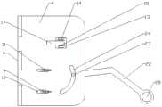
图3为本发明的打开后的结构示意图;Fig. 3 is the structure diagram after opening of the present invention;
图4为图3中A-A向的截面结构示意图。Fig. 4 is a schematic cross-sectional structure diagram along A-A in Fig. 3 .
图中,1主安全装置,2副安全装置,3连接件,4主板,5副板,6铰链,7固定齿条,8活动齿条,9滑块,10长条形孔,11回位弹簧,12橡胶垫圈,13镂空孔,14固定轴,15扭力弹簧,16弹性钩,17折弯段,18固定钩,19倾斜面,20铰轴,21偏心圆板,22拉板,23导向杆,24主导向孔,25圆形堵头,26副导向孔,27圆弧形,28拉环。In the figure, 1 main safety device, 2 secondary safety devices, 3 connectors, 4 main board, 5 sub boards, 6 hinge, 7 fixed rack, 8 movable rack, 9 slider, 10 long hole, 11 back position Spring, 12 rubber washer, 13 hollow hole, 14 fixed shaft, 15 torsion spring, 16 elastic hook, 17 bending section, 18 fixed hook, 19 inclined surface, 20 hinge shaft, 21 eccentric circular plate, 22 pull plate, 23 guide Rod, 24 main guide holes, 25 circular plugs, 26 secondary guide holes, 27 circular arcs, 28 pull rings.
具体实施方式Detailed ways
附图为本发明的具体实施例。如图1至图4所示,该种安全带用吊绳锁定装置,包括主安全装置1和副安全装置2,主安全装置1和副安全装置2结构相同,二者之间通过连接件3连接,连接件3可以是铁链子、绳子或者两个钥匙扣等,只要能使两个安装装置松散地连接到一起就行;使用时副安全装置2在上,主安全装置1在下。Accompanying drawing is the specific embodiment of the present invention. As shown in Figures 1 to 4, this kind of safety belt sling locking device includes a main safety device 1 and a secondary safety device 2. Connect, connector 3 can be iron chain, rope or two key chains etc., as long as can make two mounting devices be connected together loosely; During use, auxiliary safety device 2 is on top, and main safety device 1 is on the bottom.
主安全装置1和副主安全装置1都包括:主板4和副板5,主板4和副板5的一侧通过铰链6铰接在一起,连接件3的一端固定在副安全装置2的主板4的下端,一端固定在主安全装置1的主板4的上端;在主板4上靠近铰链6的地方固定安装一块上下方向的固定齿条7,固定齿条7的牙背对铰链6,在固定齿条7下半部分的对面有一块活动齿条8,活动齿条8的牙面向固定齿条7,活动齿条8的背面有两块滑块9,相应于滑块9的滑动轨迹的地方的主板4上开一条长条形孔10,滑块9位于长条形孔10内,起到滑块9的导航作用,使其做直线运动,为了方便活动齿条8回弹,在主板4背面固定安装两根回位弹簧11,一块滑块9配套一根回位弹簧11,回位弹簧11的一端固定在主板4背面,一端固定在滑块9上。Both the main safety device 1 and the sub-main safety device 1 include: a main board 4 and a sub-board 5, one side of the main board 4 and the sub-board 5 are hinged together by a hinge 6, and one end of the connecting piece 3 is fixed on the main board 4 of the sub-safety device 2 One end is fixed on the upper end of the main board 4 of the main safety device 1; a fixed rack 7 in the up and down direction is fixedly installed on the main board 4 near the hinge 6, and the tooth back of the fixed rack 7 faces the hinge 6. There is a movable rack 8 on the opposite side of the lower part of the bar 7, the teeth of the movable rack 8 face the fixed rack 7, and there are two sliders 9 on the back side of the movable rack 8, corresponding to the sliding track of the slider 9. A
在活动齿条8的上方安装一个橡胶垫圈12,橡胶垫圈12、固定齿条7和活动齿条8的厚度是一样的。A
在活动齿条8和橡胶垫圈12之间的主板4上有一个镂空孔13,镂空孔13处安装一根固定轴14,固定轴14上套一根扭力弹簧15和一根弹性钩16,扭力弹簧15的一端固定在主板4上,一端固定在弹性钩16上,通过按压弹性钩16使扭力弹簧15产生变形,从而带动弹性钩16活动,弹性钩16主体部分位于主板4正面,弹性钩16还有一个折弯段17位于主板4背面,通过折弯段17也能使扭力弹簧15发生变形。弹性钩上有两个环分别套在固定轴的两端,扭力弹簧位于两个环之间。There is a
在副板5上固定安装一个固定钩18,固定钩18和弹性钩16的端面都是倾斜面19,两个倾斜面19的倾斜方向和角度是一致的,固定钩18的倾斜面19按压弹性钩16的倾斜面19,可以使扭力弹簧15产生变形,带动弹性钩16转动,当固定钩18的倾斜面19越过弹性钩16的倾斜面19,弹性钩16回弹,固定钩18和弹性钩16相互钩在一起,从而将主板4和副板5固定到一起。A
在活动齿条8旁边通过铰轴20铰接一块偏心圆板21,偏心圆板21与一块拉板22一体制成,通过转动拉板22可以推动活动齿条8向固定齿条7靠近,拉板22上横穿一根导向杆23,在主板4上开一个以铰轴20为圆心的主导向孔24,拉板22背面的导向杆23位于主导向孔24内,拉板22正面的导向杆23的端部为圆形堵头25,在副板5上开一个副导向孔26,副导向孔26上端为能容圆形通过的圆弧形27,主板4和副板5合到一起后,主导向孔24与副导向孔26重合,转动拉板22后,导向杆23在主导向孔24和副导向孔26内滑行,圆形堵头25也起到主板4和副板5的固定作用,拉板22的自由端为一个拉环28,用于系安全带;由于铰轴20有凸点,因此在副板5对应的地方开一个小孔,将铰轴20的凸点露出来。Next to the movable rack 8, an eccentric circular plate 21 is hinged by a
使用时,即使拉板22的导向杆23触碰到主导向孔24的最下端不能转动时,偏心圆板21离铰轴20的最远点的位置也不高于铰轴20的高度,这样可以保证偏心圆板21起到最大作用,牢固夹紧吊绳。During use, even if the guide rod 23 of the
铰接在一起的主板4和副板5,所述主板4上设有固定齿条7,所述齿条对面设有活动齿条8;在主板4上通过铰轴20铰接有拉板22,所述拉板22与铰轴20铰接的一端为偏心圆板21,所述拉板22端部设有拉环28;所述主板4上开有以铰轴20为圆心的主导向孔24,所述主导向孔24上设有导向杆23,所述导向杆23的背向主导向孔24的一端设有圆形堵头25;所述副板5上设有副导向孔26,主板4与副板5合到一起后,主导向孔24与副导向孔26重合,所述副导向孔26的上端为能容圆形堵头25通过的圆弧形27;当拉环28到达主导向孔24的最下端时,偏心圆板21的离铰轴20最远的位置点不高于铰轴20的高度。The main board 4 and the sub-board 5 hinged together, the main board 4 is provided with a fixed rack 7, and the opposite side of the rack is provided with a movable rack 8; the main board 4 is hinged with a
使用过程如下:将安全带先系在主安全装置1的拉板22的拉环28上,然后再系在副安全装置2的拉板22的拉环28上,一定要系紧,两个拉环28之间的安全带的长度小于连接件3的最大长度;The use process is as follows: tie the seat belt on the
将吊绳依次穿过副安全装置2和主安全装置1的固定齿条7和活动齿条8之间的空隙,也是橡胶垫圈12和固定齿条7之间的空隙,副安全装置2在上,主安全装置1在下,然后合上副板5,固定钩18推动弹性钩16转动,然后相互钩在一起,圆形堵头25从副导向孔26的圆弧形27部分穿过,转动拉板22,导向杆23顺着主导向孔24和副导向孔26向下转动,偏心圆板21转动将活动齿条8推向固定齿条7,从而将吊绳初步夹紧。使用过程中一旦遇到危险,施工者坠落过程中施工者身上的安全带被扯紧,带动拉板22进一步转动将活动齿条8推至极点,吊绳被紧紧夹住,从而保护了施工者的安全。坠落过程中如果主安全装置1由于受力等原因失去功能,那么这是副安全装置2就起作用了,两个拉环28之间的安全带被扯紧,副安全装置2上的固定齿条7和活动齿条8也将吊绳夹紧,从而保证了施工者的安全,起到了双保险的作用。Pass the lifting rope through the gap between the fixed rack 7 and the movable rack 8 of the auxiliary safety device 2 and the main safety device 1 in turn, which is also the gap between the
除说明书所述技术特征外,其余技术特征均为本领域技术人员已知技术。Except for the technical features described in the description, the rest of the technical features are known to those skilled in the art.
Claims (8)
Translated fromChinesePriority Applications (1)
| Application Number | Priority Date | Filing Date | Title |
|---|---|---|---|
| CN202210717270.9ACN115138006B (en) | 2022-06-23 | 2022-06-23 | Lifting rope locking device for safety belt |
Applications Claiming Priority (1)
| Application Number | Priority Date | Filing Date | Title |
|---|---|---|---|
| CN202210717270.9ACN115138006B (en) | 2022-06-23 | 2022-06-23 | Lifting rope locking device for safety belt |
Publications (2)
| Publication Number | Publication Date |
|---|---|
| CN115138006A CN115138006A (en) | 2022-10-04 |
| CN115138006Btrue CN115138006B (en) | 2023-02-28 |
Family
ID=83408249
Family Applications (1)
| Application Number | Title | Priority Date | Filing Date |
|---|---|---|---|
| CN202210717270.9AExpired - Fee RelatedCN115138006B (en) | 2022-06-23 | 2022-06-23 | Lifting rope locking device for safety belt |
Country Status (1)
| Country | Link |
|---|---|
| CN (1) | CN115138006B (en) |
Citations (6)
| Publication number | Priority date | Publication date | Assignee | Title |
|---|---|---|---|---|
| CN2762831Y (en)* | 2005-01-14 | 2006-03-08 | 葛俭玲 | Extension safety rig |
| CN105107102A (en)* | 2015-09-28 | 2015-12-02 | 上海船舶研究设计院 | Climber protecting device |
| CN205391499U (en)* | 2016-03-28 | 2016-07-27 | 安徽省特种设备检测院 | A safety belt for high altitude special equipment detects |
| WO2017165980A1 (en)* | 2016-03-31 | 2017-10-05 | Bradley Burke | Fall control system and method of controlling a movement during fall event |
| CN113026561A (en)* | 2021-03-15 | 2021-06-25 | 穆勇攀 | High-speed construction safety device |
| CN114602078A (en)* | 2022-03-14 | 2022-06-10 | 江西正强电瓷电器有限公司 | Electric power iron tower high altitude construction anti-falling device of reverse locking function |
Family Cites Families (1)
| Publication number | Priority date | Publication date | Assignee | Title |
|---|---|---|---|---|
| FR2929125B1 (en)* | 2008-03-26 | 2013-03-15 | Jean Louis Pierre Rene Rocourt | APPARATUS FOR SECURING EMERGENCIES CARRIED OUT BY HELITREUILLAGE |
- 2022
- 2022-06-23CNCN202210717270.9Apatent/CN115138006B/ennot_activeExpired - Fee Related
Patent Citations (6)
| Publication number | Priority date | Publication date | Assignee | Title |
|---|---|---|---|---|
| CN2762831Y (en)* | 2005-01-14 | 2006-03-08 | 葛俭玲 | Extension safety rig |
| CN105107102A (en)* | 2015-09-28 | 2015-12-02 | 上海船舶研究设计院 | Climber protecting device |
| CN205391499U (en)* | 2016-03-28 | 2016-07-27 | 安徽省特种设备检测院 | A safety belt for high altitude special equipment detects |
| WO2017165980A1 (en)* | 2016-03-31 | 2017-10-05 | Bradley Burke | Fall control system and method of controlling a movement during fall event |
| CN113026561A (en)* | 2021-03-15 | 2021-06-25 | 穆勇攀 | High-speed construction safety device |
| CN114602078A (en)* | 2022-03-14 | 2022-06-10 | 江西正强电瓷电器有限公司 | Electric power iron tower high altitude construction anti-falling device of reverse locking function |
Also Published As
| Publication number | Publication date |
|---|---|
| CN115138006A (en) | 2022-10-04 |
Similar Documents
| Publication | Publication Date | Title |
|---|---|---|
| CN112701617A (en) | Tool for entering 500kV compact electric transmission line electric field and electric field entering method | |
| CN115138006B (en) | Lifting rope locking device for safety belt | |
| CN205739839U (en) | A kind of steel wire rope wood clamp with anti-slip function | |
| US4881622A (en) | Safety grab protection device | |
| CN205283013U (en) | Cable retention device with cam lock | |
| CN209700686U (en) | A rail transit vehicle brake parking brake remote release device | |
| CN219016656U (en) | Suspension device for ADSS optical cable tension-resistant hardware fitting | |
| CN103863942A (en) | Lifting hook anti-unhooking apparatus | |
| CN217025033U (en) | A hook device with automatic decoupling | |
| CN109202951A (en) | A kind of holding finger of antiskid, gripper jaw and clamper | |
| CN217276622U (en) | Three-pulley tension sensor | |
| CN212953888U (en) | Iron tower assemblage protection tool | |
| US4111388A (en) | Vertical pipe holding tool | |
| CN212250690U (en) | A hydraulic jacking protection platform hydraulic cylinder top support head | |
| CN108202199A (en) | A kind of explosive welding overturns tooling with steel plate | |
| US2245977A (en) | Tongs | |
| CN105967056A (en) | Clip type special lifting hook for electric pole | |
| CN207759850U (en) | A kind of special lifting rope device of limiter of speed verification | |
| CN207166019U (en) | The lossless fixing-line device of contact line | |
| CN217148280U (en) | Steel rail lifting appliance device | |
| CN219875007U (en) | Fixing and unloading device for tower crane cable | |
| JP3755788B2 (en) | Hydraulic piping equipment | |
| CN219708863U (en) | Steel coil lifting device | |
| CN220926069U (en) | Novel shaped steel hoist and mount device | |
| CN210286454U (en) | Safety sling fixing device for equipment compartment |
Legal Events
| Date | Code | Title | Description |
|---|---|---|---|
| PB01 | Publication | ||
| PB01 | Publication | ||
| SE01 | Entry into force of request for substantive examination | ||
| SE01 | Entry into force of request for substantive examination | ||
| GR01 | Patent grant | ||
| GR01 | Patent grant | ||
| TR01 | Transfer of patent right | ||
| TR01 | Transfer of patent right | Effective date of registration:20231117 Address after:27th floor, No. 1568 Century Avenue, China (Shanghai) pilot Free Trade Zone, Pudong New Area, Shanghai, 200120 Patentee after:CHINA CONSTRUCTION EIGHTH ENGINEERING DIVISION Co.,Ltd. Address before:Room 202, Unit 2, Building 39, Dianliuzhuang, Licheng District, Jinan City, Shandong Province, 250000 Patentee before:Zhang Han | |
| CF01 | Termination of patent right due to non-payment of annual fee | ||
| CF01 | Termination of patent right due to non-payment of annual fee | Granted publication date:20230228 |