CN115137485A - Instrument driving box and minimally invasive surgery robot - Google Patents
Instrument driving box and minimally invasive surgery robotDownload PDFInfo
- Publication number
- CN115137485A CN115137485ACN202210751735.2ACN202210751735ACN115137485ACN 115137485 ACN115137485 ACN 115137485ACN 202210751735 ACN202210751735 ACN 202210751735ACN 115137485 ACN115137485 ACN 115137485A
- Authority
- CN
- China
- Prior art keywords
- rope
- pull rope
- transmission
- shaft
- steering
- Prior art date
- Legal status (The legal status is an assumption and is not a legal conclusion. Google has not performed a legal analysis and makes no representation as to the accuracy of the status listed.)
- Granted
Links
Images


Classifications
- A—HUMAN NECESSITIES
- A61—MEDICAL OR VETERINARY SCIENCE; HYGIENE
- A61B—DIAGNOSIS; SURGERY; IDENTIFICATION
- A61B34/00—Computer-aided surgery; Manipulators or robots specially adapted for use in surgery
- A61B34/30—Surgical robots
- A—HUMAN NECESSITIES
- A61—MEDICAL OR VETERINARY SCIENCE; HYGIENE
- A61B—DIAGNOSIS; SURGERY; IDENTIFICATION
- A61B34/00—Computer-aided surgery; Manipulators or robots specially adapted for use in surgery
- A61B34/70—Manipulators specially adapted for use in surgery
- A61B34/71—Manipulators operated by drive cable mechanisms
- A—HUMAN NECESSITIES
- A61—MEDICAL OR VETERINARY SCIENCE; HYGIENE
- A61B—DIAGNOSIS; SURGERY; IDENTIFICATION
- A61B34/00—Computer-aided surgery; Manipulators or robots specially adapted for use in surgery
- A61B34/30—Surgical robots
- A61B2034/305—Details of wrist mechanisms at distal ends of robotic arms
Landscapes
- Health & Medical Sciences (AREA)
- Surgery (AREA)
- Engineering & Computer Science (AREA)
- Life Sciences & Earth Sciences (AREA)
- Biomedical Technology (AREA)
- Robotics (AREA)
- Nuclear Medicine, Radiotherapy & Molecular Imaging (AREA)
- Heart & Thoracic Surgery (AREA)
- Medical Informatics (AREA)
- Molecular Biology (AREA)
- Animal Behavior & Ethology (AREA)
- General Health & Medical Sciences (AREA)
- Public Health (AREA)
- Veterinary Medicine (AREA)
- Manipulator (AREA)
Abstract
Description
Translated fromChinese技术领域technical field
本发明涉及医疗器械技术领域,具体而言,涉及一种器械驱动盒及微创手术机器人。The present invention relates to the technical field of medical instruments, in particular, to an instrument drive box and a minimally invasive surgical robot.
背景技术Background technique
目前微创手术是医疗技术研究热点,是未来手术发展趋势,这主要是由于微创医疗有诸多优点:诸如创伤小、住院时间短、恢复快、术后并发症少。但是传统内窥镜手术有诸多弊端,例如操作精度低,视野范围小,操作自由度小,医生容易疲劳和颤抖。At present, minimally invasive surgery is a research hotspot in medical technology, and it is the future development trend of surgery. This is mainly due to the many advantages of minimally invasive medical treatment: such as less trauma, shorter hospital stay, faster recovery, and fewer postoperative complications. However, traditional endoscopic surgery has many drawbacks, such as low operation precision, small field of view, small degree of freedom of operation, and doctors are prone to fatigue and tremors.
随着科学技术发展,机器人医疗辅助技术能够很好地解决这些问题。机器人辅助技术能够提供更好的视野,便于医生操作,微创手术机器人大大增加了手术操作灵活性,医生能够进行更精细的操作。微创手术机器人一般由医生控制台、手术臂系统组成,其中手术臂系统一般由多个持械臂和一个持镜臂组成,持械臂用于夹持手术器械并按照医生指令完成相应动作,持械臂上安装有器械驱动盒。With the development of science and technology, robotic medical assistance technology can solve these problems very well. Robot-assisted technology can provide a better field of vision, which is convenient for doctors to operate. Minimally invasive surgical robots greatly increase the flexibility of surgical operations, and doctors can perform more delicate operations. A minimally invasive surgical robot is generally composed of a doctor's console and a surgical arm system. The surgical arm system is generally composed of multiple robotic arms and one mirror-holding arm. The robotic arm is used to grip surgical instruments and complete corresponding actions according to the doctor's instructions. An instrument drive box is mounted on the holding arm.
但是,现有的微创手术机器人中的器械驱动盒仍然存在操作自由度小、体积大的问题。However, the instrument drive box in the existing minimally invasive surgical robot still has the problems of small freedom of operation and large volume.
发明内容SUMMARY OF THE INVENTION
本发明提供了一种器械驱动盒及微创手术机器人,以解决现有技术中的器械驱动盒操作自由度小、体积大的问题。The invention provides an instrument drive box and a minimally invasive surgical robot, so as to solve the problems of small operation freedom and large volume of the instrument drive box in the prior art.
为了解决上述问题,根据本发明的一个方面,本发明提供了一种器械驱动盒,包括底座、固定架、驱动部和执行部,驱动部固定于底座和/或固定架,并与执行部相连以驱动其执行不同的动作,底座与固定架固定连接,执行部包括空心杆、第一齿轮和设置在空心杆一端的操作部,第一齿轮套设在空心杆另一端上,空心杆可转动地设置在底座上;驱动部包括齿传动部、多个绳传动部、多个拉绳组、导向部和转向部;齿传动部包括第一传动轴和套设在第一传动轴上的第二齿轮,第二齿轮与第一齿轮啮合以驱动空心杆自转;多个绳传动部可转动地设置在底座上;多个拉绳组分别用于与操作部的不同结构连接,以驱动操作部的不同结构分别转动,多个拉绳组均包括第一拉绳和第二拉绳,第一拉绳的一端缠绕在绳传动部上,第一拉绳穿过空心杆,第一拉绳的另一端和操作部连接,第二拉绳的一端缠绕在绳传动部上,第二拉绳穿过空心杆,第二拉绳的另一端和操作部连接,第一拉绳和第二拉绳在绳传动部上的缠绕方向相反;其中,导向部固定于底座和固定架之间,用于将拉绳组沿水平方向引导至转向部,转向部固定于固定架,用于将拉绳组沿竖直方向引导至空心杆。In order to solve the above problems, according to an aspect of the present invention, the present invention provides an instrument drive box, comprising a base, a fixing frame, a driving part and an execution part, the driving part is fixed on the base and/or the fixing frame, and is connected with the execution part In order to drive it to perform different actions, the base is fixedly connected with the fixing frame, the execution part includes a hollow rod, a first gear and an operation part arranged on one end of the hollow rod, the first gear is sleeved on the other end of the hollow rod, and the hollow rod can rotate The driving part includes a tooth transmission part, a plurality of rope transmission parts, a plurality of pulling rope groups, a guide part and a turning part; the tooth transmission part includes a first transmission shaft and a first transmission shaft sleeved on the first transmission shaft. Two gears, the second gear meshes with the first gear to drive the hollow rod to rotate; a plurality of rope transmission parts are rotatably arranged on the base; a plurality of pulling rope groups are respectively used to connect with different structures of the operation part to drive the operation part The different structures are rotated respectively, and the plurality of pull rope groups include a first pull rope and a second pull rope, one end of the first pull rope is wound on the rope transmission part, the first pull rope passes through the hollow rod, and the first pull rope The other end is connected with the operation part, one end of the second pull rope is wound on the rope transmission part, the second pull rope passes through the hollow rod, the other end of the second pull rope is connected with the operation part, the first pull rope and the second pull rope The winding directions on the rope transmission part are opposite; wherein, the guide part is fixed between the base and the fixing frame, and is used to guide the pull rope group to the steering part in the horizontal direction; Guide vertically to the hollow rod.
进一步地,导向部包括导向轴、大导向轮和小导向轮,导向轴设置在底座上,大导向轮和小导向轮沿竖直方向相邻叠置在导向轴上且相对于底座可转动。Further, the guide part includes a guide shaft, a large guide wheel and a small guide wheel, the guide shaft is arranged on the base, and the large guide wheel and the small guide wheel are adjacently stacked on the guide shaft in the vertical direction and are rotatable relative to the base.
进一步地,转向部包括转向轴、大转向轮和小转向轮,转向轴设置在固定架上且轴向垂直于绳传动部的轴向,大转向轮和小转向轮沿水平方向相邻叠置在转向轴上且相对于固定架可转动;其中,大转向轮和小转向轮分别与一个拉绳组的第一拉绳和第二拉绳配合。Further, the steering part includes a steering shaft, a large steering wheel and a small steering wheel, the steering shaft is arranged on the fixing frame and its axial direction is perpendicular to the axial direction of the rope transmission part, and the large steering wheel and the small steering wheel are adjacently stacked along the horizontal direction. It is rotatable on the steering shaft and relative to the fixing frame; wherein, the large steering wheel and the small steering wheel are respectively matched with the first pulling rope and the second pulling rope of a pulling rope group.
进一步地,转向轴可转动地设置在固定架上,大转向轮可转动地设置在转向轴上,小转向轮固定设置在转向轴上。Further, the steering shaft is rotatably arranged on the fixing frame, the large steering wheel is rotatably arranged on the steering shaft, and the small steering wheel is fixedly arranged on the steering shaft.
进一步地,绳传动部和拉绳组均为三个,转向部包括两个第一转向部和一个第二转向部,两个第一转向部的第一转向轴的轴线与一个第二转向部的第二转向轴的轴线在水平面上垂直。Further, there are three rope transmission parts and rope groups, the steering part includes two first steering parts and a second steering part, and the axes of the first steering shafts of the two first steering parts are connected with a second steering part. The axis of the second steering shaft is vertical on the horizontal plane.
进一步地,固定架包括固定板和设置在固定板上的安装块、上支柱,转向部可转动地设置在安装块上,底座包括底板和设置在底板上的下支柱,其中,上支柱和底板连接,下支柱和固定板连接。Further, the fixing frame includes a fixing plate, a mounting block and an upper column arranged on the fixing plate, the steering part is rotatably arranged on the mounting block, and the base includes a bottom plate and a lower column arranged on the bottom plate, wherein the upper column and the bottom plate are Connection, lower strut and fixed plate connection.
根据本发明的另一个方面,本发明提供了一种器械驱动盒,包括:底座;执行部,执行部包括空心杆、第一齿轮和设置在空心杆一端的操作部,第一齿轮套设在空心杆上,空心杆可转动地设置在底座上;齿传动部,齿传动部包括第一传动轴和套设在第一传动轴上的第二齿轮,第二齿轮和第一齿轮啮合;绳传动部,绳传动部可转动地设置在底座上;拉绳组,拉绳组包括第一拉绳和第二拉绳,第一拉绳的一端缠绕在绳传动部上,第一拉绳穿过空心杆,第一拉绳的另一端和操作部连接,第二拉绳的一端缠绕在绳传动部上,第二拉绳穿过空心杆,第二拉绳的另一端和操作部连接,第一拉绳和第二拉绳在绳传动部上的缠绕方向相反;其中,绳传动部和拉绳组均为多个,多个绳传动部和多个拉绳组一一对应配合,多个拉绳组用于与操作部的不同结构连接,以驱动操作部的不同结构分别移动。According to another aspect of the present invention, the present invention provides an instrument drive box, comprising: a base; an execution part, the execution part includes a hollow rod, a first gear and an operating part disposed at one end of the hollow rod, the first gear is sleeved on On the hollow rod, the hollow rod is rotatably arranged on the base; the tooth transmission part includes a first transmission shaft and a second gear sleeved on the first transmission shaft, and the second gear meshes with the first gear; the rope The transmission part, the rope transmission part is rotatably arranged on the base; the rope group, the rope group includes a first rope and a second rope, one end of the first rope is wound on the rope transmission part, and the first rope passes through the rope transmission part. Passing through the hollow rod, the other end of the first rope is connected with the operation part, one end of the second rope is wound on the rope transmission part, the second rope passes through the hollow rod, and the other end of the second rope is connected with the operation part, The winding directions of the first pull rope and the second pull rope on the rope transmission part are opposite; wherein, there are multiple rope transmission parts and pull rope groups, and the multiple rope transmission parts and the multiple pull rope groups are matched in one-to-one correspondence. Each pull cord set is used to connect with different structures of the operation part, so as to drive the different structures of the operation part to move respectively.
进一步地,绳传动部包括:传动轴,可正转及反转地设置在底座上;第一传动轮,设置在传动轴上,第一拉绳的一端缠绕在第一传动轮上;第二传动轮,设置在传动轴上,第二拉绳的一端缠绕在第二传动轮上。Further, the rope transmission part includes: a transmission shaft, which is arranged on the base so as to rotate forwardly and reversely; a first transmission wheel, which is arranged on the transmission shaft, and one end of the first pulling rope is wound on the first transmission wheel; The transmission wheel is arranged on the transmission shaft, and one end of the second pulling rope is wound on the second transmission wheel.
进一步地,第一传动轮包括:第一套体,套设在传动轴上;第一卡套,和第一套体固定连接,第一卡套可拆卸地固定在传动轴上。Further, the first transmission wheel includes: a first sleeve body sleeved on the transmission shaft; a first clamping sleeve fixedly connected with the first sleeve body, and the first clamping sleeve is detachably fixed on the transmission shaft.
进一步地,器械驱动盒还包括导向部,导向部包括导向轴、大导向轮和小导向轮,导向轴可转动地设置在底座上,大导向轮可转动地设置在导向轴上,小导向轮设置在导向轴上;导向部为多个,多个导向部和多个拉绳组一一对应设置,其中,拉绳组的第一拉绳绕在对应的导向部的大导向轮上,拉绳组的第二拉绳绕在对应的导向部的小导向轮上。Further, the instrument drive box also includes a guide portion, the guide portion includes a guide shaft, a large guide wheel and a small guide wheel, the guide shaft is rotatably arranged on the base, the large guide wheel is rotatably arranged on the guide shaft, and the small guide wheel is rotatably arranged on the guide shaft. It is arranged on the guide shaft; there are multiple guide parts, and the multiple guide parts and the multiple pull rope groups are arranged in one-to-one correspondence, wherein the first pull rope of the pull rope group is wound around the large guide wheel of the corresponding guide part, and the pull rope is pulled. The second pull rope of the rope group is wound around the small guide wheel of the corresponding guide part.
进一步地,器械驱动盒还包括:固定架,固定架和底座连接;第一转向部,第一转向部包括第一转向轴、第一大转向轮和第一小转向轮,第一转向轴可转动地设置在固定架上,第一转向轴的轴向垂直于绳传动部的轴向,第一大转向轮可转动地设置在第一转向轴上,第一小转向轮设置在第一转向轴上;其中,第一大转向轮和第一小转向轮分别与一个拉绳组的第一拉绳和第二拉绳配合。Further, the instrument drive box also includes: a fixing frame, the fixing frame is connected with the base; a first steering part, the first steering part includes a first steering shaft, a first large steering wheel and a first small steering wheel, and the first steering shaft can be It is rotatably arranged on the fixing frame, the axial direction of the first steering shaft is perpendicular to the axial direction of the rope transmission part, the first large steering wheel is rotatably arranged on the first steering shaft, and the first small steering wheel is arranged on the first steering wheel On the shaft; wherein, the first large steering wheel and the first small steering wheel are respectively matched with the first pulling rope and the second pulling rope of a pulling rope group.
进一步地,器械驱动盒还包括:第二转向部,第二转向部包括第二转向轴、第二大转向轮和第二小转向轮,第二转向轴可转动地设置在固定架上,第二转向轴的轴向垂直于绳传动部的轴向及第一转向轴的轴向,第二大转向轮可转动地设置在第二转向轴上,第二小转向轮设置在第二转向轴上;其中,第二大转向轮和第二小转向轮分别与一个拉绳组的第一拉绳和第二拉绳配合。Further, the instrument drive box further includes: a second steering part, the second steering part includes a second steering shaft, a second large steering wheel and a second small steering wheel, the second steering shaft is rotatably arranged on the fixing frame, the first steering shaft The axial direction of the two steering shafts is perpendicular to the axial direction of the rope transmission part and the axial direction of the first steering shaft, the second large steering wheel is rotatably arranged on the second steering shaft, and the second small steering wheel is arranged on the second steering shaft Wherein, the second large steering wheel and the second small steering wheel are respectively matched with the first pull rope and the second pull rope of a pull rope group.
进一步地,绳传动部和拉绳组均为三个,第一转向部包括两个第一大转向轮和两个第一小转向轮,第一转向部和第二转向部均为一个,其中,第一转向部和三个拉绳组中的两个配合,第二转向部和三个拉绳组中的另一个配合。Further, there are three rope transmission parts and rope groups, the first steering part includes two first large steering wheels and two first small steering wheels, and both the first steering part and the second steering part are one, wherein , the first steering part cooperates with two of the three pulling rope groups, and the second steering part cooperates with the other one of the three pulling rope groups.
进一步地,固定架包括固定板和设置在固定板上的安装块、上支柱,第一转向轴可转动地设置在安装块上,底座包括底板和设置在底板上的下支柱,其中,上支柱和底板连接,下支柱和固定板连接。Further, the fixing frame includes a fixing plate, a mounting block and an upper pillar arranged on the fixing plate, the first steering shaft is rotatably arranged on the mounting block, and the base includes a bottom plate and a lower pillar arranged on the bottom plate, wherein the upper pillar is It is connected with the bottom plate, and the lower pillar is connected with the fixed plate.
进一步地,操作部包括:腕部结构,腕部结构和空心杆的一端铰接;第一小爪,和腕部结构铰接;第二小爪,和腕部结构铰接,腕部结构、第一小爪和第二小爪分别和不同的拉绳组连接。Further, the operation part includes: a wrist structure, the wrist structure is hinged with one end of the hollow rod; the first small claw is hinged with the wrist structure; the second small claw is hinged with the wrist structure, the wrist structure, the first small claw is hinged with the wrist structure, The claw and the second small claw are respectively connected with different pulling rope groups.
根据本发明的又一个方面,本发明提供了一种微创手术机器人,微创手术机器人包括上述的器械驱动盒。According to another aspect of the present invention, the present invention provides a minimally invasive surgical robot, which includes the above-mentioned instrument drive box.
应用本发明的技术方案,提供了一种器械驱动盒,包括:底座;执行部,执行部包括空心杆、第一齿轮和设置在空心杆一端的操作部,第一齿轮套设在空心杆上,空心杆可转动地设置在底座上;齿传动部,齿传动部包括第一传动轴和套设在第一传动轴上的第二齿轮,第二齿轮和第一齿轮啮合;绳传动部,绳传动部可转动地设置在底座上;拉绳组,拉绳组包括第一拉绳和第二拉绳,第一拉绳的一端缠绕在绳传动部上,第一拉绳穿过空心杆,第一拉绳的另一端和操作部连接,第二拉绳的一端缠绕在绳传动部上,第二拉绳穿过空心杆,第二拉绳的另一端和操作部连接,第一拉绳和第二拉绳在绳传动部上的缠绕方向相反;其中,绳传动部和拉绳组均为多个,多个绳传动部和多个拉绳组一一对应配合,多个拉绳组用于与操作部的不同结构连接,以驱动操作部的不同结构分别移动。采用该方案,通过第一齿轮和第二齿轮的啮合,可实现执行部的转动,即操作部能够进行转动。采用第一拉绳和第二拉绳以不同螺旋方向分别缠绕在绳传动部和操作部上,这样多个绳传动部在转动时能够实现操作部的不同的结构正转或反转,此种方式可实现操作部在多个自由度上的移动,并且,采用多组拉绳进行传动结构紧凑,这样可以减小器械驱动盒的体积。且安装起来比较简单,在安装时通过拉紧拉绳即可实现预紧,从而保证了传动精度。By applying the technical solution of the present invention, an instrument drive box is provided, comprising: a base; an execution part, the execution part includes a hollow rod, a first gear and an operation part arranged at one end of the hollow rod, and the first gear is sleeved on the hollow rod , the hollow rod is rotatably arranged on the base; the tooth transmission part includes a first transmission shaft and a second gear sleeved on the first transmission shaft, and the second gear meshes with the first gear; the rope transmission part, The rope transmission part is rotatably arranged on the base; the rope group includes a first rope and a second rope, one end of the first rope is wound on the rope transmission part, and the first rope passes through the hollow rod , the other end of the first rope is connected with the operation part, one end of the second rope is wound on the rope transmission part, the second rope passes through the hollow rod, the other end of the second rope is connected with the operation part, the first rope The winding directions of the rope and the second rope are opposite on the rope transmission part; wherein, there are multiple rope transmission parts and rope groups, and the rope transmission parts and the rope groups are matched in one-to-one correspondence, and the rope transmission parts and the rope groups are in one-to-one correspondence. The group is used to connect with different structures of the operation part to drive the different structures of the operation part to move respectively. With this solution, through the meshing of the first gear and the second gear, the rotation of the execution part can be realized, that is, the operation part can be rotated. The first pull rope and the second pull rope are respectively wound on the rope transmission part and the operation part in different helical directions, so that the multiple rope transmission parts can realize the forward or reverse rotation of different structures of the operation part when rotating. In this way, the movement of the operating part can be realized in multiple degrees of freedom, and the transmission structure is compact by using multiple sets of pulling ropes, which can reduce the volume of the instrument drive box. And the installation is relatively simple, and the pre-tightening can be achieved by tightening the pull rope during installation, thereby ensuring the transmission accuracy.
附图说明Description of drawings
构成本申请的一部分的说明书附图用来提供对本发明的进一步理解,本发明的示意性实施例及其说明用于解释本发明,并不构成对本发明的不当限定。在附图中:The accompanying drawings forming a part of the present application are used to provide further understanding of the present invention, and the exemplary embodiments of the present invention and their descriptions are used to explain the present invention and do not constitute an improper limitation of the present invention. In the attached image:
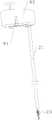
图1示出了本发明的实施例提供的器械驱动盒的结构示意图;FIG. 1 shows a schematic structural diagram of an instrument drive box provided by an embodiment of the present invention;
图2示出了图1中的器械驱动盒的爆炸图;Figure 2 shows an exploded view of the instrument drive box of Figure 1;
图3示出了图2中的器械驱动盒中的部分结构的示意图;FIG. 3 shows a schematic diagram of a part of the structure of the instrument drive box in FIG. 2;
图4示出了图3中第一转向部和第二转向部的局部放大图;Fig. 4 shows a partial enlarged view of the first turning portion and the second turning portion in Fig. 3;
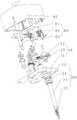
图5示出了图2中的器械驱动盒中的部分结构的示意图;Fig. 5 shows the schematic diagram of part of the structure in the instrument drive box in Fig. 2;
图6示出了图2中执行部和部分底座的结构图;Fig. 6 shows the structural diagram of the execution part and part of the base in Fig. 2;
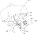
图7示出了图1中的器械驱动盒在另一视角的爆炸图;Figure 7 shows an exploded view of the instrument drive box of Figure 1 from another perspective;
图8示出了本发明的实施例提供的微创手术机器人的结构示意图。FIG. 8 shows a schematic structural diagram of a minimally invasive surgical robot provided by an embodiment of the present invention.
其中,上述附图包括以下附图标记:Wherein, the above-mentioned drawings include the following reference signs:
10、底座;11、底板;12、下支柱;13、凸柱;20、执行部;21、空心杆;22、第一齿轮;23、操作部;231、腕部结构;232、第一小爪;233、第二小爪;24、轴承;30、齿传动部;31、第一传动轴;32、第二齿轮;40、绳传动部;41、传动轴;42、第一传动轮;421、第一套体;422、第一卡套;4221、第一半环形件;4222、第二半环形件;43、第二传动轮;50、导向部;51、导向轴;52、大导向轮;53、小导向轮;60、固定架;61、固定板;62、安装块;63、上支柱;70、第一转向部;71、第一转向轴;72、第一大转向轮;73、第一小转向轮;80、第二转向部;81、第二转向轴;82、第二大转向轮;83、第二小转向轮;91、压杆;92、外壳;100、器械驱动盒;200、机械臂。10, base; 11, bottom plate; 12, lower pillar; 13, convex column; 20, executive part; 21, hollow rod; 22, first gear; 23, operation part; 231, wrist structure; 232, first small Claw; 233, second small claw; 24, bearing; 30, tooth transmission part; 31, first transmission shaft; 32, second gear; 40, rope transmission part; 41, transmission shaft; 42, first transmission wheel; 421, the first sleeve body; 422, the first ferrule; 4221, the first half-ring piece; 4222, the second half-ring piece; 43, the second transmission wheel; 50, the guide part; 51, the guide shaft; 52, the large Guide wheel; 53, small guide wheel; 60, fixed frame; 61, fixed plate; 62, installation block; 63, upper support; 70, first steering part; 71, first steering shaft; 72, first large steering wheel ; 73, the first small steering wheel; 80, the second steering part; 81, the second steering shaft; 82, the second large steering wheel; 83, the second small steering wheel; 91, the pressure rod; 92, the shell; 100, Instrument drive box; 200, robotic arm.
具体实施方式Detailed ways
下面将结合本发明实施例中的附图,对本发明实施例中的技术方案进行清楚、完整地描述。显然,所描述的实施例仅仅是本发明一部分实施例,而不是全部的实施例。以下对至少一个示例性实施例的描述实际上仅仅是说明性的,决不作为对本发明及其应用或使用的任何限制。基于本发明中的实施例,本领域普通技术人员在没有作出创造性劳动前提下所获得的所有其他实施例,都属于本发明保护的范围。The technical solutions in the embodiments of the present invention will be clearly and completely described below with reference to the accompanying drawings in the embodiments of the present invention. Obviously, the described embodiments are only some, but not all, embodiments of the present invention. The following description of at least one exemplary embodiment is merely illustrative in nature and is in no way intended to limit the invention, its application, or uses. Based on the embodiments of the present invention, all other embodiments obtained by those of ordinary skill in the art without creative efforts shall fall within the protection scope of the present invention.
如图1至图7所示,本发明的实施例提供了一种器械驱动盒,包括:底座10;执行部20,执行部20包括空心杆21、第一齿轮22和设置在空心杆21一端的操作部23,第一齿轮22套设在空心杆21上,空心杆21可转动地设置在底座10上;齿传动部30,齿传动部30包括第一传动轴31和套设在第一传动轴31上的第二齿轮32,第二齿轮32和第一齿轮22啮合;绳传动部40,绳传动部40可转动地设置在底座10上;拉绳组,拉绳组包括第一拉绳和第二拉绳,第一拉绳的一端缠绕在绳传动部40上,第一拉绳穿过空心杆21,第一拉绳的另一端和操作部23连接,第二拉绳的一端缠绕在绳传动部40上,第二拉绳穿过空心杆21,第二拉绳的另一端和操作部23连接,第一拉绳和第二拉绳在绳传动部40上的缠绕方向相反;其中,绳传动部40和拉绳组均为多个,多个绳传动部40和多个拉绳组一一对应配合,多个拉绳组用于与操作部23的不同结构连接,以驱动操作部23的不同结构分别移动。As shown in FIG. 1 to FIG. 7 , an embodiment of the present invention provides an instrument drive box, including: a
采用该方案,通过第一齿轮22和第二齿轮32的啮合,可实现执行部20的转动,即操作部23能够进行转动;空心杆21的设置能够使拉绳组顺利穿过与操作部23连接,这样结构更加紧凑。采用第一拉绳和第二拉绳以不同螺旋方向分别缠绕在绳传动部40和操作部23上,这样多个绳传动部40在转动时能够实现操作部23的不同的结构正转或反转,此种方式可实现操作部23在多个自由度上的移动,并且,采用多组拉绳进行传动结构紧凑,这样可以减小器械驱动盒的体积。且安装起来比较简单,在安装时通过拉紧拉绳即可实现预紧,从而保证了传动精度。With this solution, through the meshing of the
其中,绳传动部40包括:传动轴41,可正转及反转地设置在底座10上;第一传动轮42,设置在传动轴41上,第一拉绳的一端缠绕在第一传动轮42上;第二传动轮43,设置在传动轴41上,第二拉绳的一端缠绕在第二传动轮43上。传动轴41在进行正反转运动时带动第一传动轮42和第二传动轮43转动,可使第一拉绳和第二拉绳实现不同螺旋方向的运动,从而带动操作部23转动。Wherein, the
如图2所示,在本方案中,传动轴41与底座10之间设有轴承,传动轴41与固定架60之间也设有轴承,这样可使传动轴41更稳定地实现正转及反转,并且,本方案中还设置有挡圈,通过挡圈抵住轴承,使轴承不易发生脱落。As shown in FIG. 2, in this solution, a bearing is provided between the
具体地,第一传动轮42包括:第一套体421,套设在传动轴41上;第一卡套422,和第一套体421固定连接,第一卡套422可拆卸地固定在传动轴41上。第一套体421套设在传动轴41上,便于拆卸;第一卡套422和第一套体421固定连接,便于加工和装配。Specifically, the
可选地,在本实施例中,第一套体421的外壁上具有螺旋形的凹槽,第一拉绳的一端缠绕在凹槽内。通过设置凹槽,能够对第一拉绳起到限位作用,使绳传动部40与操作部23之间的传动更加稳定可靠。第一套体421上具有限位孔,第一拉绳的端部穿过限位孔,限位孔的设置能够固定和拉紧第一拉绳。通过上述方案可实现精确传动,减小或避免转动回差。Optionally, in this embodiment, the outer wall of the
如图5所示,第一卡套422包括第一半环形件4221和第二半环形件4222,其中,第一半环形件4221和第一套体421为一体结构,第一半环形件4221和第二半环形件4222的凹槽相对设置以夹住传动轴41,第一半环形件4221和第二半环形件4222通过两个紧固件固定连接。采用上述设置,便于安装和拆卸,紧固件可选用螺栓连接,从图5中可以看出,第一半环形件4221和第二半环形件4222之间留有缝隙,这样可使两者连接更为紧固可靠。要实现该目的,可将第一半环形件4221和/或第二半环形件4222的环形设置得比半圆环略小。本实施例中,是将第二半环形件4222的环形设置得比半圆环略小。As shown in FIG. 5 , the
在本实施例中,器械驱动盒还包括导向部50,导向部50包括导向轴51、大导向轮52和小导向轮53,导向轴51可转动地设置在底座10上,大导向轮52可转动地设置在导向轴51上,小导向轮53设置在导向轴51上;导向部50为多个,多个导向部50和多个拉绳组一一对应设置,其中,拉绳组的第一拉绳绕在对应的导向部50的大导向轮52上,拉绳组的第二拉绳绕在对应的导向部50的小导向轮53上。In this embodiment, the instrument drive box further includes a
导向部50的设置可对拉绳组起到导向作用,以使拉绳按照需要的路径传动。导向轴51与底座10之间设有轴承,大导向轮52与导向轴51之间设有轴承,小导向轮53与导向轴51可为键连接,采用上述设置能够实现大导向轮52与小导向轮53在不同方向的转动。其中,大导向轮52与第一拉绳配合,小导向轮53与第二拉绳配合。多个导向部50与多个拉绳组一一对应,能够实现操作部23的多个操作自由度,并且使器械驱动盒结构紧凑。可以理解的是,只要是能够实现大导向轮52与小导向轮53在不同方向的转动的机构都可以适用,例如,大导向轮52与小导向轮53各自设置一个轴承,再将轴承分别套设在导向轴51,此时导向轴51无需转动,可与底座10固定装配或者一体成型。The setting of the
如图5所示,导向轴51平行于传动轴41,可避免两者在运行时发生干涉;其中导向部还包括挡圈,用于抵住轴承,使轴承不易发生脱落。As shown in FIG. 5 , the
在本实施例中,器械驱动盒还包括:固定架60,固定架60和底座10连接;第一转向部70,第一转向部70包括第一转向轴71、第一大转向轮72和第一小转向轮73,第一转向轴71可转动地设置在固定架60上,第一转向轴71的轴向垂直于绳传动部40的轴向,第一大转向轮72可转动地设置在第一转向轴71上,第一小转向轮73设置在第一转向轴71上;其中,第一大转向轮72和第一小转向轮73分别与一个拉绳组的第一拉绳和第二拉绳配合。In this embodiment, the instrument drive box further includes: a fixing frame 60, which is connected to the
通过设置第一转向部70,第一转向轴71与绳传动部40的轴向垂直,能够使拉绳组实现转向,从而使拉绳组通过空心杆21。第一转向轴71与固定架60之间设有轴承,第一大转向轮72与第一转向轴71之间设有轴承,第一小转向轮73与第一转向轴71可为键连接,采用上述设置能够实现第一大转向轮72与第一小转向轮73在不同方向的转动。其中,第一大转向轮72为两个,第一小转向轮73为两个,分别与两个拉绳组的第一拉绳和第二拉绳一一对应。同理,此处也是只要是能够实现第一大转向轮72与第一小转向轮73在不同方向的转动的机构都可以适用。By arranging the first steering portion 70 , the
在本实施例中,器械驱动盒还包括:第二转向部80,第二转向部80包括第二转向轴81、第二大转向轮82和第二小转向轮83,第二转向轴81可转动地设置在固定架60上,第二转向轴81的轴向垂直于绳传动部40的轴向及第一转向轴71的轴向,第二大转向轮82可转动地设置在第二转向轴81上,第二小转向轮83设置在第二转向轴81上;其中,第二大转向轮82和第二小转向轮83分别与一个拉绳组的第一拉绳和第二拉绳配合。In this embodiment, the instrument drive box further includes: a
通过设置第二转向部80,第二转向轴81与绳传动部40的轴向垂直,能够使拉绳组实现转向,从而使拉绳组通过空心杆21。第二转向轴81与固定架60之间设有轴承,第二大转向轮82与第二转向轴81之间设有轴承,第二小转向轮83与第二转向轴81可为键连接,采用上述设置能够实现第二大转向轮82与第二小转向轮83在不同方向的转动。其中,第二大转向轮82对应第一拉绳,第二小转向轮83对应第二拉绳。同理,此处也是只要是能够实现第二大转向轮82与第二小转向轮83在不同方向的转动的机构都可以适用。By arranging the
具体地,绳传动部40和拉绳组均为三个,第一转向部70包括两个第一大转向轮72和两个第一小转向轮73,第一转向部70和第二转向部80均为一个,其中,第一转向部70和三个拉绳组中的两个配合,第二转向部80和三个拉绳组中的另一个配合。通过设置三个绳传动部40和拉绳组,能够使操作部23实现三个操作自由度,大大提高了操作的灵活性。Specifically, there are three
具体地,固定架60包括固定板61和设置在固定板61上的安装块62、上支柱63,第一转向轴71可转动地设置在安装块62上,底座10包括底板11和设置在底板11上的下支柱12,其中,上支柱63和底板11连接,下支柱12和固定板61连接。安装块62的设置,用于安装第一转向部70和第二转向部80,对其起到支撑和定位的作用。第一转向轴71与安装块62之间设有轴承;上支柱63与底板11卡接,下支柱12与固定板61卡接,便于安装和拆卸。Specifically, the fixing frame 60 includes a fixing
在本实施例中,器械驱动盒还包括安装板、驱动部,驱动部设置在安装板上,驱动部与绳传动部40驱动连接。器械驱动盒还包括设置在安装板上的卡钩,卡钩和底座10卡接,从而实现安装板和底座10的连接。In this embodiment, the instrument driving box further includes a mounting plate and a driving part, the driving part is arranged on the mounting plate, and the driving part is drivingly connected with the
在本实施例中,器械驱动盒还包括压杆91,压杆91可转动地设置在底座10上,压杆91在转动时可推动卡钩,以使卡钩和底座10脱离。器械驱动盒还包括弹性件,弹性件的一端和固定板61抵接,弹性件的另一端和压杆91抵接。在操作时,按压压杆91,压杆91克服弹性件的弹力后转动,从而推动卡钩移动。其中,弹性件中设置有杆件,用于支撑弹性件,防止脱落。In this embodiment, the instrument drive box further includes a
进一步地,器械驱动盒还包括外壳92,外壳92罩住固定板61,外壳92和底板11连接。外壳92与底板11可采用卡接方式连接,容易安装和拆卸。器械驱动盒还包括连接轴,底板11上设置有凸柱13,连接轴穿过压杆91,连接轴的一端与凸柱13铰接。连接轴的另一端和外壳92铰接,在按压压杆91时,压杆91绕连接轴转动。Further, the instrument drive box further includes a
其中,执行部20还包括:轴承24,设置在底座10内,空心杆21和轴承24的内圈配合;挡圈,设置在底座10内,挡圈和轴承24的外圈限位配合。通过轴承24的设置,能够使空心杆21在正转及反转时减小阻力;挡圈的设置能够抵住轴承24,起到限位的作用,使轴承24不易脱落,提高结构的稳定性。The
其中,操作部23包括:腕部结构231,腕部结构231和空心杆21的一端铰接;第一小爪232,和腕部结构231铰接;第二小爪233,和腕部结构231铰接,腕部结构231、第一小爪232和第二小爪233分别和不同的拉绳组连接。腕部结构231与空心杆21的一端铰接,能够实现腕部结构231的转动;第一小爪232和第二小爪233与腕部结构231铰接,可实现第一小爪232和第二小爪233的转动,即第一小爪232和第二小爪233之间的张开和闭合。其中,采用铰接方式连接,便于安装和拆卸。腕部结构231、第一小爪232和第二小爪233分别和不同的拉绳组连接,能够通过不同拉绳组进行分别控制,可根据实际工作需求,对其分别进行调节,提高了操作的灵活性。The
如图8所示,本发明的另一实施例提供了一种微创手术机器人,微创手术机器人包括上述的器械驱动盒100。具体地,微创手术机器人包括机械臂200,器械驱动盒100设置在机械臂200上,这样可通过机械臂200带动器械驱动盒100整体移动,例如上下移动。进一步地,微创手术机器人中可设置多个机械臂200,每个机械臂200上均设置一个器械驱动盒100,这样多个器械驱动盒100可协同操作,以提高手术的便利性。并且,不同的器械驱动盒100中可设置功能不同的操作部,这样可以满足不同的手术需求,丰富微创手术机器人的功能。As shown in FIG. 8 , another embodiment of the present invention provides a minimally invasive surgical robot. The minimally invasive surgical robot includes the above-mentioned
以上所述仅为本发明的优选实施例而已,并不用于限制本发明,对于本领域的技术人员来说,本发明可以有各种更改和变化。凡在本发明的精神和原则之内,所作的任何修改、等同替换、改进等,均应包含在本发明的保护范围之内。The above descriptions are only preferred embodiments of the present invention, and are not intended to limit the present invention. For those skilled in the art, the present invention may have various modifications and changes. Any modification, equivalent replacement, improvement, etc. made within the spirit and principle of the present invention shall be included within the protection scope of the present invention.
Claims (10)
Priority Applications (1)
| Application Number | Priority Date | Filing Date | Title |
|---|---|---|---|
| CN202210751735.2ACN115137485B (en) | 2021-08-04 | 2021-08-04 | Instrument drive box and minimally invasive surgical robot |
Applications Claiming Priority (2)
| Application Number | Priority Date | Filing Date | Title |
|---|---|---|---|
| CN202210751735.2ACN115137485B (en) | 2021-08-04 | 2021-08-04 | Instrument drive box and minimally invasive surgical robot |
| CN202110893562.3ACN113693729B (en) | 2021-08-04 | 2021-08-04 | Instrument driving box and minimally invasive surgery robot |
Related Parent Applications (1)
| Application Number | Title | Priority Date | Filing Date |
|---|---|---|---|
| CN202110893562.3ADivisionCN113693729B (en) | 2021-08-04 | 2021-08-04 | Instrument driving box and minimally invasive surgery robot |
Publications (2)
| Publication Number | Publication Date |
|---|---|
| CN115137485Atrue CN115137485A (en) | 2022-10-04 |
| CN115137485B CN115137485B (en) | 2024-11-08 |
Family
ID=78651613
Family Applications (2)
| Application Number | Title | Priority Date | Filing Date |
|---|---|---|---|
| CN202110893562.3AActiveCN113693729B (en) | 2021-08-04 | 2021-08-04 | Instrument driving box and minimally invasive surgery robot |
| CN202210751735.2AActiveCN115137485B (en) | 2021-08-04 | 2021-08-04 | Instrument drive box and minimally invasive surgical robot |
Family Applications Before (1)
| Application Number | Title | Priority Date | Filing Date |
|---|---|---|---|
| CN202110893562.3AActiveCN113693729B (en) | 2021-08-04 | 2021-08-04 | Instrument driving box and minimally invasive surgery robot |
Country Status (1)
| Country | Link |
|---|---|
| CN (2) | CN113693729B (en) |
Families Citing this family (2)
| Publication number | Priority date | Publication date | Assignee | Title |
|---|---|---|---|---|
| CN114469268B (en)* | 2022-02-15 | 2023-08-15 | 常州唯精医疗机器人有限公司 | Surgical instrument driving mechanism, ultrasonic knife and minimally invasive surgical robot |
| CN117856511B (en)* | 2024-03-01 | 2024-06-18 | 科弛医疗科技(北京)有限公司 | Motor heat abstractor, apparatus actuating mechanism and surgical robot device |
Citations (5)
| Publication number | Priority date | Publication date | Assignee | Title |
|---|---|---|---|---|
| CN105286999A (en)* | 2015-10-15 | 2016-02-03 | 天津大学 | Minimally invasive surgery instrument with tail end self-rotation function |
| DE102015215469A1 (en)* | 2015-08-13 | 2017-02-16 | Richard Wolf Gmbh | Instrument, in particular medical endoscopic instrument |
| WO2018040706A1 (en)* | 2016-08-31 | 2018-03-08 | 微创(上海)医疗机器人有限公司 | Transmission mechanism and surgical instrument |
| CN112043390A (en)* | 2020-09-30 | 2020-12-08 | 深圳市精锋医疗科技有限公司 | Surgical instrument, slave operation device, and surgical robot |
| CN213787764U (en)* | 2020-11-19 | 2021-07-27 | 山东威高手术机器人有限公司 | Snakelike surgical instrument |
Family Cites Families (6)
| Publication number | Priority date | Publication date | Assignee | Title |
|---|---|---|---|---|
| US9326788B2 (en)* | 2012-06-29 | 2016-05-03 | Ethicon Endo-Surgery, Llc | Lockout mechanism for use with robotic electrosurgical device |
| JP2016117126A (en)* | 2014-12-20 | 2016-06-30 | ライフロボティクス株式会社 | Robot arm mechanism |
| WO2018041205A1 (en)* | 2016-08-31 | 2018-03-08 | 北京术锐技术有限公司 | Sterilizable flexible surgical instrument system |
| CN209404841U (en)* | 2018-10-24 | 2019-09-20 | 首都医科大学附属北京友谊医院 | A multi-degree-of-freedom minimally invasive surgical instrument |
| CN111166487B (en)* | 2018-11-13 | 2024-12-24 | 重庆金山医疗机器人有限公司 | Instrument transmission clutch structure, method and surgical assisting robot instrument system |
| CN111374716B (en)* | 2018-12-29 | 2024-12-20 | 达科为(深圳)医疗设备有限公司 | A surgical knife assembly and mounting seat thereof |
- 2021
- 2021-08-04CNCN202110893562.3Apatent/CN113693729B/enactiveActive
- 2021-08-04CNCN202210751735.2Apatent/CN115137485B/enactiveActive
Patent Citations (5)
| Publication number | Priority date | Publication date | Assignee | Title |
|---|---|---|---|---|
| DE102015215469A1 (en)* | 2015-08-13 | 2017-02-16 | Richard Wolf Gmbh | Instrument, in particular medical endoscopic instrument |
| CN105286999A (en)* | 2015-10-15 | 2016-02-03 | 天津大学 | Minimally invasive surgery instrument with tail end self-rotation function |
| WO2018040706A1 (en)* | 2016-08-31 | 2018-03-08 | 微创(上海)医疗机器人有限公司 | Transmission mechanism and surgical instrument |
| CN112043390A (en)* | 2020-09-30 | 2020-12-08 | 深圳市精锋医疗科技有限公司 | Surgical instrument, slave operation device, and surgical robot |
| CN213787764U (en)* | 2020-11-19 | 2021-07-27 | 山东威高手术机器人有限公司 | Snakelike surgical instrument |
Also Published As
| Publication number | Publication date |
|---|---|
| CN113693729A (en) | 2021-11-26 |
| CN113693729B (en) | 2022-08-05 |
| CN115137485B (en) | 2024-11-08 |
Similar Documents
| Publication | Publication Date | Title |
|---|---|---|
| CN113693729B (en) | Instrument driving box and minimally invasive surgery robot | |
| CN201015585Y (en) | endoscope | |
| EP1859724B1 (en) | Electric bending endoscope device and endoscope supporting device | |
| US20180214226A1 (en) | Surgical robot | |
| CN111956328B (en) | Continuum robot for minimally invasive surgery | |
| US11219496B2 (en) | Surgical tool, medical treatment instrument, and surgical system | |
| WO2005055840A1 (en) | Manipulator with multiple degrees of freedom | |
| US20200206955A1 (en) | Robotic hand | |
| CN105012022B (en) | Integrated surgical instrument drive device with decoupling function | |
| CN113288440B (en) | A minimally invasive interventional surgical robot based on multi-segment continuum series structure | |
| CN110693539A (en) | Minimally invasive surgery instrument for driving single-side flat plate arrangement | |
| WO2022227854A1 (en) | Rear-end transmission apparatus, medical instrument and surgical robot | |
| CN111407412A (en) | Natural cavity operation end manipulator | |
| JPWO2018203425A1 (en) | Medical treatment tools and surgical systems | |
| JP2008212451A (en) | Surgical manipulator | |
| CN219206854U (en) | Traction rope adjusting mechanism, handle and endoscope | |
| CN209153974U (en) | A surgical instrument with a mobile positioning joint for a single-hole surgical robot | |
| CN117260754B (en) | Flexible surgical robot | |
| CN219070434U (en) | Instrument transmission device, surgical instrument and surgical robot | |
| CN115302495B (en) | Rotatable mechanical arm driven by stay wire | |
| CN116269788A (en) | Proximal end driving structure of flexible arm | |
| WO2023226828A1 (en) | Laparoscopic surgical instrument and surgical robot | |
| CN112043391B (en) | Surgical instruments, operating equipment and surgical robots | |
| CN118043099A (en) | Medical device | |
| CN113693728A (en) | Endoscope transmission box and minimally invasive surgery robot |
Legal Events
| Date | Code | Title | Description |
|---|---|---|---|
| PB01 | Publication | ||
| PB01 | Publication | ||
| SE01 | Entry into force of request for substantive examination | ||
| SE01 | Entry into force of request for substantive examination | ||
| TA01 | Transfer of patent application right | Effective date of registration:20240815 Address after:310000, Floor 1, Building 1 and 1-4, Building 2, No. 39, Keji Avenue, Yuhang Street, Yuhang District, Hangzhou City, Zhejiang Province Applicant after:Hangzhou Weijing medical robot Co.,Ltd. Country or region after:China Address before:213023 No. g064, Changzhou Zhonglou hi tech entrepreneurship service center, No. 213, Yulong South Road, Zhonglou Economic Development Zone, Changzhou City, Jiangsu Province Applicant before:Changzhou Weijing medical robot Co.,Ltd. Country or region before:China | |
| TA01 | Transfer of patent application right | ||
| GR01 | Patent grant | ||
| GR01 | Patent grant | ||
| CP03 | Change of name, title or address | Address after:311121 Hangzhou City, Yuhang District, Yuhang Street, Keji Avenue 39, Building 1, first floor, Building 2, first to fourth floors Patentee after:Hangzhou Kangji Weijing Medical Robot Co.,Ltd. Country or region after:China Address before:Building 1, 1st Floor, and Building 2, 1-4 Floors, No. 39 Keji Avenue, Yuhang Street, Yuhang District, Hangzhou City, Zhejiang Province Patentee before:Hangzhou Weijing medical robot Co.,Ltd. Country or region before:China | |
| CP03 | Change of name, title or address |