CN115137415A - An in-vivo blocking and clamping device - Google Patents
An in-vivo blocking and clamping deviceDownload PDFInfo
- Publication number
- CN115137415A CN115137415ACN202210835295.9ACN202210835295ACN115137415ACN 115137415 ACN115137415 ACN 115137415ACN 202210835295 ACN202210835295 ACN 202210835295ACN 115137415 ACN115137415 ACN 115137415A
- Authority
- CN
- China
- Prior art keywords
- disc
- disk
- clamping
- shaped
- fixed
- Prior art date
- Legal status (The legal status is an assumption and is not a legal conclusion. Google has not performed a legal analysis and makes no representation as to the accuracy of the status listed.)
- Pending
Links
Images


Classifications
- A—HUMAN NECESSITIES
- A61—MEDICAL OR VETERINARY SCIENCE; HYGIENE
- A61B—DIAGNOSIS; SURGERY; IDENTIFICATION
- A61B17/00—Surgical instruments, devices or methods
- A61B17/0057—Implements for plugging an opening in the wall of a hollow or tubular organ, e.g. for sealing a vessel puncture or closing a cardiac septal defect
- A—HUMAN NECESSITIES
- A61—MEDICAL OR VETERINARY SCIENCE; HYGIENE
- A61B—DIAGNOSIS; SURGERY; IDENTIFICATION
- A61B17/00—Surgical instruments, devices or methods
- A61B17/00234—Surgical instruments, devices or methods for minimally invasive surgery
- A61B2017/00238—Type of minimally invasive operation
- A61B2017/00243—Type of minimally invasive operation cardiac
- A—HUMAN NECESSITIES
- A61—MEDICAL OR VETERINARY SCIENCE; HYGIENE
- A61B—DIAGNOSIS; SURGERY; IDENTIFICATION
- A61B17/00—Surgical instruments, devices or methods
- A61B17/0057—Implements for plugging an opening in the wall of a hollow or tubular organ, e.g. for sealing a vessel puncture or closing a cardiac septal defect
- A61B2017/00575—Implements for plugging an opening in the wall of a hollow or tubular organ, e.g. for sealing a vessel puncture or closing a cardiac septal defect for closure at remote site, e.g. closing atrial septum defects
- A61B2017/00592—Elastic or resilient implements
- A—HUMAN NECESSITIES
- A61—MEDICAL OR VETERINARY SCIENCE; HYGIENE
- A61B—DIAGNOSIS; SURGERY; IDENTIFICATION
- A61B17/00—Surgical instruments, devices or methods
- A61B17/0057—Implements for plugging an opening in the wall of a hollow or tubular organ, e.g. for sealing a vessel puncture or closing a cardiac septal defect
- A61B2017/00575—Implements for plugging an opening in the wall of a hollow or tubular organ, e.g. for sealing a vessel puncture or closing a cardiac septal defect for closure at remote site, e.g. closing atrial septum defects
- A61B2017/00597—Implements comprising a membrane
- A—HUMAN NECESSITIES
- A61—MEDICAL OR VETERINARY SCIENCE; HYGIENE
- A61B—DIAGNOSIS; SURGERY; IDENTIFICATION
- A61B17/00—Surgical instruments, devices or methods
- A61B17/0057—Implements for plugging an opening in the wall of a hollow or tubular organ, e.g. for sealing a vessel puncture or closing a cardiac septal defect
- A61B2017/00575—Implements for plugging an opening in the wall of a hollow or tubular organ, e.g. for sealing a vessel puncture or closing a cardiac septal defect for closure at remote site, e.g. closing atrial septum defects
- A61B2017/00615—Implements with an occluder on one side of the opening and holding means therefor on the other
- A—HUMAN NECESSITIES
- A61—MEDICAL OR VETERINARY SCIENCE; HYGIENE
- A61B—DIAGNOSIS; SURGERY; IDENTIFICATION
- A61B17/00—Surgical instruments, devices or methods
- A61B17/0057—Implements for plugging an opening in the wall of a hollow or tubular organ, e.g. for sealing a vessel puncture or closing a cardiac septal defect
- A61B2017/00575—Implements for plugging an opening in the wall of a hollow or tubular organ, e.g. for sealing a vessel puncture or closing a cardiac septal defect for closure at remote site, e.g. closing atrial septum defects
- A61B2017/00623—Introducing or retrieving devices therefor
- A—HUMAN NECESSITIES
- A61—MEDICAL OR VETERINARY SCIENCE; HYGIENE
- A61B—DIAGNOSIS; SURGERY; IDENTIFICATION
- A61B17/00—Surgical instruments, devices or methods
- A61B17/0057—Implements for plugging an opening in the wall of a hollow or tubular organ, e.g. for sealing a vessel puncture or closing a cardiac septal defect
- A61B2017/00575—Implements for plugging an opening in the wall of a hollow or tubular organ, e.g. for sealing a vessel puncture or closing a cardiac septal defect for closure at remote site, e.g. closing atrial septum defects
- A61B2017/00632—Occluding a cavity, i.e. closing a blind opening
- A—HUMAN NECESSITIES
- A61—MEDICAL OR VETERINARY SCIENCE; HYGIENE
- A61B—DIAGNOSIS; SURGERY; IDENTIFICATION
- A61B17/00—Surgical instruments, devices or methods
- A61B2017/00982—General structural features
- A61B2017/00991—Telescopic means
Landscapes
- Health & Medical Sciences (AREA)
- Surgery (AREA)
- Life Sciences & Earth Sciences (AREA)
- Medical Informatics (AREA)
- Nuclear Medicine, Radiotherapy & Molecular Imaging (AREA)
- Engineering & Computer Science (AREA)
- Biomedical Technology (AREA)
- Heart & Thoracic Surgery (AREA)
- Cardiology (AREA)
- Molecular Biology (AREA)
- Animal Behavior & Ethology (AREA)
- General Health & Medical Sciences (AREA)
- Public Health (AREA)
- Veterinary Medicine (AREA)
- Surgical Instruments (AREA)
- Prostheses (AREA)
Abstract
Description
Translated fromChinese技术领域technical field
本发明涉及介入治疗器械技术领域,具体涉及一种体内封堵夹持器械。The invention relates to the technical field of interventional treatment devices, in particular to an in vivo blocking and clamping device.
背景技术Background technique
卵圆孔未闭是指婴幼儿的原发膈和继发膈在发育过程中未完全融合,形成裂隙样的通道,即为PFO(Patent Foramen Ovale)。成年人的PFO发生概率为25%。近年来,PFO与不明原因卒中(Cryptogenic Stroke)的相关研究表明,PFO可能为不明原因卒中患者隐蔽的栓塞源。因此,对于PFO相关卒中患者,经导管封堵PFO手术成为相对较优的选择。Patent foramen ovale refers to the incomplete fusion of the primary diaphragm and the secondary diaphragm in infants and young children to form a slit-like channel, which is PFO (Patent Foramen Ovale). The incidence of PFO in adults is 25%. In recent years, related studies on PFO and unexplained stroke (Cryptogenic Stroke) have shown that PFO may be a hidden source of embolism in patients with unexplained stroke. Therefore, for PFO-related stroke patients, transcatheter closure of PFO has become a relatively superior option.
目前临床上采用的主要是传统双圆盘状的封堵器,对于主动脉根部凸出并紧靠卵圆窝的患者,这种结构的封堵器容易对患者主动脉根部造成磨损。另外,现有的封堵器仅在针对原发膈和继发膈交叠较短的病例相对有效,但是在临床中发现一些患者原发膈和继发膈的交叠长度较长,有的甚至能够达到15-20mm,现有封堵器对于交叠部分的组织不友好,交叠的组织堆积在双圆盘状封堵器的腰部后,会在原发膈和继发膈之间会产生很大的残余分流。At present, the traditional double disc-shaped occluder is mainly used clinically. For patients whose aortic root protrudes and is close to the fossa ovalis, the occluder with this structure is easy to cause wear and tear to the aortic root of the patient. In addition, the existing occluder is relatively effective only in cases where the primary diaphragm and the secondary diaphragm overlap are relatively short. It can even reach 15-20mm. The existing occluder is not friendly to the overlapping tissue. After the overlapping tissue accumulates on the waist of the double disc occluder, it will accumulate between the primary diaphragm and the secondary diaphragm. A large residual shunt is produced.
发明内容SUMMARY OF THE INVENTION
本发明的目的在于提供一种体内封堵夹持器械,以解决现有技术中存在的传统封堵器容易对患者主动脉根部造成磨损,仅对原发膈和继发膈交叠较短的病例相对有效,对于交叠部分的组织不友好,交叠的组织堆积在双圆盘状封堵器的腰部后,会在原发膈和继发膈之间会产生很大的残余分流的技术问题。The purpose of the present invention is to provide an in vivo occlusion and clamping device, so as to solve the problem that the traditional occluder in the prior art is easy to cause abrasion to the aortic root of the patient, and only the primary diaphragm and the secondary diaphragm overlap short The case is relatively effective, and it is not friendly to the overlapping part of the tissue. After the overlapping tissue accumulates at the waist of the double disc occluder, it will produce a large residual shunt between the primary diaphragm and the secondary diaphragm. question.
为了实现上述目的,本发明采用的技术方案是:In order to achieve the above object, the technical scheme adopted in the present invention is:
一种体内封堵夹持器械,包括:An in-vivo blocking and clamping device, comprising:
盘状部,弹性可变形设置以使盘状部具有可收入鞘管内的收拢姿态以及可膨开呈盘状的自由姿态;The disk-shaped portion is elastically deformable and arranged so that the disk-shaped portion has a retracted posture that can be received into the sheath tube and a free posture that can be expanded into a disk-like shape;
夹持部,固定在所述盘状部一侧面,所述夹持部弹性可变形设置,以使夹持部具有可收入鞘管内的收拢姿态以及可展开的自由姿态,所述夹持部在自由姿态时依靠弹性朝所述盘状部压紧,以使夹持部和盘状部能够配合夹持固定,所述夹持部内部设有用于容纳组织的间隙;The clamping part is fixed on a side surface of the disc-shaped part, and the clamping part is elastically deformable, so that the clamping part has a retracted posture that can be received into the sheath tube and a free posture that can be expanded; In the free posture, the plate-shaped portion is pressed against the plate-shaped portion by elasticity, so that the clamping portion and the plate-shaped portion can cooperate to be clamped and fixed, and the clamping portion is provided with a gap for accommodating the tissue;
阻流部,安装在所述盘状部和/或所述夹持部上。The flow blocking part is mounted on the disc-shaped part and/or the clamping part.
在一个实施方式中,所述夹持部包括:In one embodiment, the clamping portion includes:
若干弹性臂,均匀环绕分布,所述弹性臂包括朝所述盘状部方向延伸的末端,且弹性臂在自由姿态时,所述末端朝所述盘状部方向压紧。A plurality of elastic arms are evenly distributed around, the elastic arms include ends extending toward the disk-shaped portion, and when the elastic arms are in a free posture, the ends are pressed toward the disk-shaped portion.
在一个实施方式中,所述夹持部通过底座连接至所述盘状部,所述弹性臂包括相连呈锐角的第一弹性段和第二弹性段,所述第一弹性段端部与所述底座固定,所述第二弹性段端部朝所述盘状部方向延伸;所述第一弹性段和第二弹性段之间以及相邻所述弹性臂之间形成所述间隙。In one embodiment, the clamping part is connected to the disc-shaped part through a base, the elastic arm comprises a first elastic segment and a second elastic segment connected at an acute angle, and the end of the first elastic segment is connected to the The base is fixed, and the end of the second elastic segment extends toward the disk-shaped portion; the gap is formed between the first elastic segment and the second elastic segment and between the adjacent elastic arms.
在一个实施方式中,所述阻流部包括:In one embodiment, the flow blocking portion includes:
若干阻流套,与所述若干弹性臂一一对应,每一所述阻流套套设在对应所述弹性臂上,且若干阻流套端部连接为一体。A plurality of choke sleeves are in one-to-one correspondence with the plurality of elastic arms, each of the choke sleeves is sleeved on the corresponding elastic arm, and the ends of the plurality of choke sleeves are connected as a whole.
在一个实施方式中,所述夹持部包括呈螺旋状环绕的弹性条,所述弹性条内端与所述盘状部固定,外端通过拉条连接至所述盘状部,所述弹性条在自由姿态时展开呈盘状向所述盘状部方向压紧。In one embodiment, the clamping part comprises an elastic strip that is spirally surrounded, the inner end of the elastic strip is fixed with the disc-shaped part, and the outer end is connected to the disc-shaped part through a pulling strip, and the elastic strip is connected to the disc-shaped part. In the free posture, the strip unfolds in a disc shape and is pressed in the direction of the disc part.
在一个实施方式中,所述盘状部中心设有固定套,所述固定套包括:In one embodiment, a fixing sleeve is provided in the center of the disc-shaped portion, and the fixing sleeve includes:
伸缩段,可弹性伸缩设置,所述伸缩段一端与所述盘状部中心连接,另一端朝所述夹持部方向延伸设置;The telescopic section can be elastically telescopic, one end of the telescopic section is connected to the center of the disc-shaped portion, and the other end is extended toward the clamping portion;
固定段,固定在所述伸缩段另一端上;a fixed section, fixed on the other end of the telescopic section;
其中,所述夹持部固定在所述固定段上。Wherein, the clamping portion is fixed on the fixing section.
在一个实施方式中,所述伸缩段为管状结构,且管壁为记忆金属网,或所述伸缩段为弹簧结构。In one embodiment, the telescopic section is a tubular structure, and the tube wall is a memory metal mesh, or the telescopic section is a spring structure.
在一个实施方式中,所述伸缩段中心还设有导杆,所述导杆一端与所述盘状部中心固定,另一端穿过所述固定段设置,所述夹持部沿所述导杆可滑动设置。In one embodiment, a guide rod is further provided in the center of the telescopic section, one end of the guide rod is fixed with the center of the disc-shaped portion, and the other end is disposed through the fixed section, and the clamping portion is arranged along the guide rod. The lever is slidable to set.
在一个实施方式中,所述盘状部由袋状的弹性编织网定型而成,且盘状部的袋口部位束集固定形成固定套;或所述盘状部为由边缘连接为一体的第一编织网盘和第二编织网盘组成的双层结构,所述第一编织网盘和第二编织网盘的端部束集固定形成固定套。In one embodiment, the disc-shaped part is shaped by a bag-shaped elastic woven mesh, and the pocket parts of the disc-shaped part are bundled and fixed to form a fixed sleeve; or the disc-shaped part is integrally connected by edges A double-layer structure composed of a first woven mesh disc and a second woven mesh disc, the ends of the first woven mesh disc and the second woven mesh disc are bundled and fixed to form a fixing sleeve.
在一个实施方式中,所述阻流部包括:In one embodiment, the flow blocking portion includes:
第一阻流膜,贴覆在所述盘状部内部面向所述夹持部一侧面;a first flow blocking film, which is attached to the inner side of the disc-shaped portion facing the clamping portion;
第二阻流膜,贴覆在所述盘状部内部背离所述夹持部一侧面,且第二阻流膜在盘状部内部背离夹持部一侧面上的正投影覆盖盘状部边缘。The second flow blocking film is attached to the side of the inner portion of the disc-shaped portion away from the clamping portion, and the orthographic projection of the second flow-blocking film on the side of the inner portion of the disc-shaped portion away from the clamping portion covers the edge of the disc-shaped portion .
在一个实施方式中,所述阻流部包括:In one embodiment, the flow blocking portion includes:
第一阻流膜,贴覆在所述盘状部内部面向所述夹持部一侧面;a first flow blocking film, which is attached to the inner side of the disc-shaped portion facing the clamping portion;
第二阻流膜,设置在所述盘状部内,且第二阻流膜的边缘与盘状部边缘固定。所述第二阻流膜延伸突出盘状部边缘。The second flow blocking film is arranged in the disk-shaped portion, and the edge of the second flow blocking film is fixed to the edge of the disk-shaped portion. The second flow blocking film extends beyond the edge of the disc.
在一个实施方式中,所述第二阻流膜延伸突出盘状部边缘。In one embodiment, the second flow blocking film extends beyond the edge of the disk.
在一个实施方式中,所述夹持部在所述盘状部上的正投影超出盘状部的边缘设置。In one embodiment, the orthographic projection of the clamping portion on the disk-shaped portion is disposed beyond the edge of the disk-shaped portion.
区别于现有技术,本申请的有益效果是:Different from the prior art, the beneficial effects of the present application are:
本申请体内封堵夹持器械由盘状部和夹持部组成,其中夹持部具有较小的表面积,在与盘状部配合夹紧卵圆孔通道两侧组织的同时,有效减小血栓风险,同时避免磨损主动脉根部;The in-vivo occlusion and clamping device of the present application is composed of a disc-shaped part and a clamping part, wherein the clamping part has a small surface area, and while cooperating with the disc-shaped part to clamp the tissues on both sides of the foramen ovale channel, it can effectively reduce the thrombus risk, while avoiding abrasion of the aortic root;
本申请夹持部可折叠收纳卵圆孔通道两侧组织,有效避免残余分流;The clamping part of the present application can be folded to accommodate the tissues on both sides of the foramen ovale channel, effectively avoiding residual shunt;
本申请夹持部和盘状部之间间距可调,可适配卵圆孔通道长度不同的患者,并有效保证夹持稳定性。The distance between the clamping part and the disc-shaped part of the present application is adjustable, which can be adapted to patients with different lengths of the foramen ovale channel, and can effectively ensure the clamping stability.
附图说明Description of drawings
为了更清楚地说明本发明具体实施方式或现有技术中的技术方案,下面将对具体实施方式或现有技术描述中所需要使用的附图作简单地介绍。在所有附图中,类似的元件或部分一般由类似的附图标记标识。附图中,各元件或部分并不一定按照实际的比例绘制。In order to illustrate the specific embodiments of the present invention or the technical solutions in the prior art more clearly, the following briefly introduces the accompanying drawings that are required to be used in the description of the specific embodiments or the prior art. Similar elements or parts are generally identified by similar reference numerals throughout the drawings. In the drawings, each element or section is not necessarily drawn to actual scale.
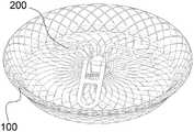
图1是本申请体内封堵夹持器械一实施方式的结构示意图;FIG. 1 is a schematic structural diagram of an embodiment of the in-vivo blocking and clamping device of the present application;
图2是本申请盘状部一实施方式的结构示意图;2 is a schematic structural diagram of an embodiment of the disc-shaped portion of the present application;
图3是本申请夹持部一实施方式的结构示意图;3 is a schematic structural diagram of an embodiment of the clamping portion of the present application;
图4是本申请体内封堵夹持器械一实施方式的剖视结构示意图;FIG. 4 is a schematic cross-sectional structural diagram of an embodiment of the in-vivo blocking and clamping device of the present application;
图5是本申请体内封堵夹持器械另一实施方式的结构示意图;5 is a schematic structural diagram of another embodiment of the in-vivo blocking and clamping device of the present application;
图6是本申请体内封堵夹持器械又一实施方式的结构示意图。FIG. 6 is a schematic structural diagram of another embodiment of the in-vivo blocking and clamping device of the present application.
100、盘状部;101、第一编织网盘;102、第二编织网盘;103、固定套;1031、伸缩段;1032、固定段;100, disc-shaped portion; 101, first woven mesh disc; 102, second woven mesh disc; 103, fixed sleeve; 1031, telescopic segment; 1032, fixed segment;
200、夹持部;201、底座;202、固定座;203、弹性臂;2031、第一弹性段;204、弹性条;205、拉条;2032、第二弹性段;200, clamping part; 201, base; 202, fixing seat; 203, elastic arm; 2031, first elastic segment; 204, elastic strip; 205, pull strip; 2032, second elastic segment;
300、阻流膜;301、阻流套;302、第一阻流膜;303、第二阻流膜。300, blocking film; 301, blocking sleeve; 302, first blocking film; 303, second blocking film.
具体实施方式Detailed ways
下面将结合附图对本发明技术方案的实施例进行详细的描述。以下实施例仅用于更加清楚地说明本发明的技术方案,因此只作为示例,而不能以此来限制本发明的保护范围。Embodiments of the technical solutions of the present invention will be described in detail below with reference to the accompanying drawings. The following examples are only used to more clearly illustrate the technical solutions of the present invention, and are therefore only used as examples, and cannot be used to limit the protection scope of the present invention.
需要注意的是,除非另有说明,本申请使用的技术术语或者科学术语应当为本发明所属领域技术人员所理解的通常意义。It should be noted that, unless otherwise specified, the technical or scientific terms used in this application should have the usual meanings understood by those skilled in the art to which the present invention belongs.
请参阅图1、图2和图3,图1是本申请体内封堵夹持器械一实施方式的结构示意图,图2是本申请盘状部100一实施方式的结构示意图,图3是本申请夹持部200一实施方式的结构示意图。Please refer to FIG. 1 , FIG. 2 and FIG. 3 , FIG. 1 is a schematic structural diagram of an embodiment of the body blocking and clamping device of the present application, FIG. 2 is a structural schematic diagram of an embodiment of the disc-shaped
该体内封堵夹持器械包括分设两侧的盘状部100和夹持部200。The in-vivo blocking and clamping device includes a disc-shaped
其中,盘状部100为双层结构,且包括边缘连接为一体的第一编织网盘101和第二编织网盘102。盘状部100中部设置有固定套103,以将编织网的端部束集固定。The disk-shaped
在其他实施方式中,盘状部100也可采用带状的弹性编织网定型而成,并通过固定套 103束集袋口部分,均能实现本实施方式的效果。In other embodiments, the disc-shaped
夹持部200固定在固定套103上,且夹持部200包括底座201,底座201上开设有与固定套103匹配的通孔,且底座201套设在固定套103上。The clamping
底座201远离固定套103一侧设置有固定座202,固定座202固定在固定套103端部从而将底座201限位在固定套103上。在一个应用场景中,可在固定套103靠近固定座202 一端外周面设置螺纹,使固定座202能够通过螺纹结构与固定套103固定,在其他应用场景中,也可采用其他固定方式,例如焊接、卡接、压接等,均能实现本实施方式的效果。A fixing
底座201的上设置均匀环绕底座201分布的三个弹性臂203,每个弹性臂203包括相连接的第一弹性段2031和第二弹性段2032。其中第一弹性段2031一端与底座201连接,第一弹性段2031另一端朝固定座202方向延伸设置,第二弹性段2032一端与第一弹性段 2031另一端连接,第二弹性端另一端朝固定座202方向延伸设置。The
当弹性臂203处于自由姿态时,第一弹性段2031和第二弹性段2032之间形成15-70度锐角。When the
弹性臂203采用镍钛合金等记忆金属制成,可以收拢介入到鞘管内输送至患处,也可以在脱离鞘管后自动复原展开。The
本实施方式中弹性臂203采用底座201和固定座202固定在固定套103上,在其他实施方式中,弹性臂203还可采用其他固定方式,例如卡接、焊接、压接等均能实现本实施方式的效果。In this embodiment, the
可以理解的,由于弹性臂203处于自由姿态时朝向盘状部100一侧压紧,从而能够使得该器械夹持固定在卵圆孔处,将卵圆孔通道两侧的组织更好的夹合贴靠在一起。并且由于弹性臂203的表面积较小,能够有效减小卵圆孔通道一侧的原发膈面侧的血栓风险。It can be understood that since the
同时,弹性臂203内第一弹性段2031和第二弹性段2032之间形成的空间以及弹性臂 203之间的空间能够收纳卵圆孔通道两侧的原发膈和继发膈的交叠褶皱,从而有效避免其产生残余分流。At the same time, the space formed between the first
为了保证本申请夹持器械的阻流效果,同时进一步避免残余分流,请参阅图4,图4是本申请体内封堵夹持器械一实施方式的剖视结构示意图。In order to ensure the flow blocking effect of the clamping device of the present application and further avoid residual shunt flow, please refer to FIG. 4 , which is a schematic cross-sectional structural diagram of an embodiment of the in-vivo blocking and clamping device of the present application.
本申请中还包括阻流部300,阻流部300包括设置在夹持部200上的阻流套301以及设置在盘状部100上的第一阻流膜302和第二阻流膜303。The present application also includes a
具体地,阻流部300包括与三个弹性臂203一一对应的三个阻流套301,阻流套301套设在对应的弹性臂203上,且三个阻流套301的端部连接为一体,整体包裹弹性臂。阻流套301一方面能够增大接触面积,避免突出结构滑入卵圆孔内,同时还能够加速内皮化过程,提高阻流效果。Specifically, the
第一阻流膜302贴覆在盘状部100内部面向夹持部200一侧面;第二阻流膜303贴覆在盘状部100内部背离夹持部200一侧面,且第二阻流膜302延伸突出盘状部100边缘。The first
盘状部100采用大小双层覆膜设计,第一阻流膜302为小盘膜,通过缝合、粘结等方式固定,更贴近心房壁能够起到直接封堵加速内皮化的效果,同时一定程度上进一步降低返流。第二阻流膜303为大盘膜,能够把残余的分流有效充分阻挡,同时第二阻流膜303 边缘局部从盘状部100边缘穿出,从而及早与人体组织贴附实现内皮化。The disc-shaped
可以理解的,在其他实施方式中,第二阻流膜302还可直接悬空在盘状部100内部,通过将第二阻流膜302与盘状部100的边缘缝合固定实现其的安装固定,均能够实现本实施方式的效果。在其他实施方式中,第二阻流膜303的边缘也可不从盘状部100的边缘穿出。It can be understood that in other embodiments, the second
由于部分患者的卵圆孔通道较长,为了进一步满足这些患者的需求,提高本申请夹持器械的普及性和适配性,请参阅图5,图5是本申请体内封堵夹持器械另一实施方式的结构示意图。Since the foramen ovale channel of some patients is relatively long, in order to further meet the needs of these patients and improve the popularity and adaptability of the clamping device of the present application, please refer to FIG. A schematic diagram of the structure of an embodiment.
如图所示,本实施方式中固定套103采用双段式设计,由伸缩段1031和固定段1032组成。其中伸缩段1031可伸缩设置,一端与盘状部100中心连接,另一端朝夹持部200方向延伸设置与固定段1032连接。As shown in the figure, in this embodiment, the fixing
夹持部200固定在固定段1032上。具体地,伸缩段1031采用弹簧结构。The clamping
可以理解的,由于伸缩段1031的存在,夹持部200和盘状部100之间的间距可以调节,从而适配不同卵圆孔通道长度的患者,并且在伸缩段1031的弹力作用下,能够进一步提高夹持部200和盘状部100之间的夹持力。It can be understood that, due to the existence of the
在其他实施方式中,伸缩段1031还可以采用管状结构,例如将镍钛金属管管壁一体化切割形成网状结构,或采用镍钛金属网变成形成,均能够实现本实施方式的效果。In other embodiments, the
进一步的,为了伸缩段1031在伸缩运动过程中导致夹持部200施力偏斜,在其他实施方式中,还可以在伸缩段1031的中心设置导杆,将导杆配置成一端与盘状部100中心固定,另一端穿过固定段1032设置。从而可以使夹持部200和固定段1032沿导杆滑动,以限定夹持部200的滑动方向,保证其施力均匀。Further, in order to cause the clamping
可以理解的,本实施方式中的夹持部200作用在于朝盘状部100方向下压以配合夹持卵圆孔通道两侧的原发膈和继发膈,同时收纳原发膈和继发膈的交叠部分以避免残余分流。其他结构的夹持部200也能够实现本实施方式的效果,请参阅图6,图6是本申请体内封堵夹持器械又一实施方式的结构示意图。It can be understood that the function of the clamping
如图所示,本实施方式中夹持部200采用呈螺旋状环绕的弹性条204,弹性条204内端与固定套103固定,外端通过拉条205连接至固定套103,弹性条204在自由姿态时展开呈盘状向盘状部100方向压紧。As shown in the figure, in this embodiment, the clamping
弹性条204可采用镍钛金属等形状记忆材料支撑,可收拢至鞘管内输送,也能在脱离鞘管后展开压向盘状部100,从而实现与盘状部100配合的夹持。The
弹性条204螺旋状环绕呈盘状,整体表面积小,能有效避免血栓风险;同时弹性条204 内部的间隙处还可收纳原发膈和继发膈的交叠部分以避免残余分流。The
可以理解的,本实施方式仅示出了当盘状部100的固定套103具有伸缩段1031时,夹持部200采用呈螺旋状环绕的弹性条204的技术方案,当固定套103采用其他结构时,呈螺旋状环绕的弹性条204仍能够作为夹持部200使用,均能够实现本实施方式的效果。It can be understood that this embodiment only shows the technical solution that when the fixing
值得注意的是,上述实施方式中示出的夹持部200在盘状部100上的正投影均完整位于盘状部100内,即夹持部200的展开面积小于盘状部100,在其他实施方式中,还可以使夹持部200在盘状部100上的正投影超出盘状部100的边缘设置,均能够实现本实施方式的效果。It should be noted that the orthographic projections of the clamping
本发明的说明书中,说明了大量具体细节。然而,能够理解,本发明的实施例可以在没有这些具体细节的情况下实践。在一些实例中,并未详细示出公知的方法、结构和技术,以便不模糊对本说明书的理解。In the description of the present invention, numerous specific details are set forth. It will be understood, however, that embodiments of the invention may be practiced without these specific details. In some instances, well-known methods, structures and techniques have not been shown in detail in order not to obscure an understanding of this description.
在本说明书的描述中,参考术语“一个实施例”、“一些实施例”、“示例”、“具体示例”、或“一些示例”等的描述意指结合该实施例或示例描述的具体特征、结构、材料或者特点包含于本发明的至少一个实施例或示例中。在本说明书中,对上述术语的示意性表述不必须针对的是相同的实施例或示例。而且,描述的具体特征、结构、材料或者特点可以在任一个或多个实施例或示例中以合适的方式结合。此外,在不相互矛盾的情况下,本领域的技术人员可以将本说明书中描述的不同实施例或示例以及不同实施例或示例的特征进行结合和组合。In the description of this specification, description with reference to the terms "one embodiment," "some embodiments," "example," "specific example," or "some examples", etc., mean specific features described in connection with the embodiment or example , structure, material or feature is included in at least one embodiment or example of the present invention. In this specification, schematic representations of the above terms are not necessarily directed to the same embodiment or example. Furthermore, the particular features, structures, materials or characteristics described may be combined in any suitable manner in any one or more embodiments or examples. Furthermore, those skilled in the art may combine and combine the different embodiments or examples described in this specification, as well as the features of the different embodiments or examples, without conflicting each other.
最后应说明的是:以上各实施例仅用以说明本发明的技术方案,而非对其限制;尽管参照前述各实施例对本发明进行了详细的说明,本领域的普通技术人员应当理解:其依然可以对前述各实施例所记载的技术方案进行修改,或者对其中部分或者全部技术特征进行等同替换;而这些修改或者替换,并不使相应技术方案的本质脱离本发明各实施例技术方案的范围,其均应涵盖在本发明的权利要求和说明书的范围当中。Finally, it should be noted that the above embodiments are only used to illustrate the technical solutions of the present invention, but not to limit them; although the present invention has been described in detail with reference to the foregoing embodiments, those of ordinary skill in the art should understand that: The technical solutions described in the foregoing embodiments can still be modified, or some or all of the technical features thereof can be equivalently replaced; and these modifications or replacements do not make the essence of the corresponding technical solutions deviate from the technical solutions of the embodiments of the present invention. The scope of the invention should be included in the scope of the claims and description of the present invention.
Claims (13)
Priority Applications (3)
| Application Number | Priority Date | Filing Date | Title |
|---|---|---|---|
| CN202210835295.9ACN115137415A (en) | 2022-07-16 | 2022-07-16 | An in-vivo blocking and clamping device |
| PCT/CN2022/128210WO2024016507A1 (en) | 2022-07-16 | 2022-10-28 | In vivo occlusion and clamping instrument |
| US19/010,570US20250134508A1 (en) | 2022-07-16 | 2025-01-06 | Vivo occlusion and clamping instrument |
Applications Claiming Priority (1)
| Application Number | Priority Date | Filing Date | Title |
|---|---|---|---|
| CN202210835295.9ACN115137415A (en) | 2022-07-16 | 2022-07-16 | An in-vivo blocking and clamping device |
Publications (1)
| Publication Number | Publication Date |
|---|---|
| CN115137415Atrue CN115137415A (en) | 2022-10-04 |
Family
ID=83412804
Family Applications (1)
| Application Number | Title | Priority Date | Filing Date |
|---|---|---|---|
| CN202210835295.9APendingCN115137415A (en) | 2022-07-16 | 2022-07-16 | An in-vivo blocking and clamping device |
Country Status (3)
| Country | Link |
|---|---|
| US (1) | US20250134508A1 (en) |
| CN (1) | CN115137415A (en) |
| WO (1) | WO2024016507A1 (en) |
Cited By (2)
| Publication number | Priority date | Publication date | Assignee | Title |
|---|---|---|---|---|
| CN116077105A (en)* | 2022-11-23 | 2023-05-09 | 先健科技(深圳)有限公司 | Plugging device and plugging system |
| WO2024016507A1 (en)* | 2022-07-16 | 2024-01-25 | 上海傲流医疗科技有限公司 | In vivo occlusion and clamping instrument |
Families Citing this family (1)
| Publication number | Priority date | Publication date | Assignee | Title |
|---|---|---|---|---|
| CN118845126A (en)* | 2024-06-30 | 2024-10-29 | 武汉唯柯医疗科技有限公司 | Occluder and occluder input system |
Citations (8)
| Publication number | Priority date | Publication date | Assignee | Title |
|---|---|---|---|---|
| CN105147350A (en)* | 2015-10-08 | 2015-12-16 | 上海形状记忆合金材料有限公司 | Self-adaptive plugging device |
| CN205054330U (en)* | 2015-10-08 | 2016-03-02 | 上海形状记忆合金材料有限公司 | Self -adaptation plugging device |
| CN105433991A (en)* | 2015-12-28 | 2016-03-30 | 先健科技(深圳)有限公司 | Closure device |
| CN205339017U (en)* | 2015-12-18 | 2016-06-29 | 上海形状记忆合金材料有限公司 | Acleistocardia plugging device that sufficiency is high |
| CN112773418A (en)* | 2020-12-31 | 2021-05-11 | 上海锦葵医疗器械股份有限公司 | Degradable heart foramen ovale closure device and manufacturing method thereof |
| CN214128635U (en)* | 2020-11-02 | 2021-09-07 | 上海形状记忆合金材料有限公司 | A kind of patent foramen ovale occluder without endomembrane tightly braided |
| CN114404110A (en)* | 2022-02-10 | 2022-04-29 | 复旦大学附属中山医院 | Plugging device with clamping piece |
| CN114711872A (en)* | 2015-12-29 | 2022-07-08 | 深圳市科奕顿生物医疗科技有限公司 | Left atrial appendage occluder |
Family Cites Families (8)
| Publication number | Priority date | Publication date | Assignee | Title |
|---|---|---|---|---|
| US7044134B2 (en)* | 1999-11-08 | 2006-05-16 | Ev3 Sunnyvale, Inc | Method of implanting a device in the left atrial appendage |
| US7226467B2 (en)* | 1999-04-09 | 2007-06-05 | Evalve, Inc. | Fixation device delivery catheter, systems and methods of use |
| US20030139819A1 (en)* | 2002-01-18 | 2003-07-24 | Beer Nicholas De | Method and apparatus for closing septal defects |
| US9186152B2 (en)* | 2010-11-12 | 2015-11-17 | W. L. Gore & Associates, Inc. | Left atrial appendage occlusive devices |
| EP2672927A4 (en)* | 2011-02-10 | 2014-08-20 | Atrial Innovations Inc | EARLY APPENDIX OCCLUSION AND TREATMENT OF ARRHYTHMIA |
| JP2023533989A (en)* | 2020-07-07 | 2023-08-07 | ラミナー インコーポレイテッド | Devices, systems and methods for treating the left atrial appendage |
| CN114099076B (en)* | 2021-11-19 | 2024-09-06 | 上海傲流医疗科技有限公司 | Clamp holder for positioning and fixing valve and narrow environment alignment system thereof |
| CN115137415A (en)* | 2022-07-16 | 2022-10-04 | 上海傲流医疗科技有限公司 | An in-vivo blocking and clamping device |
- 2022
- 2022-07-16CNCN202210835295.9Apatent/CN115137415A/enactivePending
- 2022-10-28WOPCT/CN2022/128210patent/WO2024016507A1/ennot_activeCeased
- 2025
- 2025-01-06USUS19/010,570patent/US20250134508A1/enactivePending
Patent Citations (8)
| Publication number | Priority date | Publication date | Assignee | Title |
|---|---|---|---|---|
| CN105147350A (en)* | 2015-10-08 | 2015-12-16 | 上海形状记忆合金材料有限公司 | Self-adaptive plugging device |
| CN205054330U (en)* | 2015-10-08 | 2016-03-02 | 上海形状记忆合金材料有限公司 | Self -adaptation plugging device |
| CN205339017U (en)* | 2015-12-18 | 2016-06-29 | 上海形状记忆合金材料有限公司 | Acleistocardia plugging device that sufficiency is high |
| CN105433991A (en)* | 2015-12-28 | 2016-03-30 | 先健科技(深圳)有限公司 | Closure device |
| CN114711872A (en)* | 2015-12-29 | 2022-07-08 | 深圳市科奕顿生物医疗科技有限公司 | Left atrial appendage occluder |
| CN214128635U (en)* | 2020-11-02 | 2021-09-07 | 上海形状记忆合金材料有限公司 | A kind of patent foramen ovale occluder without endomembrane tightly braided |
| CN112773418A (en)* | 2020-12-31 | 2021-05-11 | 上海锦葵医疗器械股份有限公司 | Degradable heart foramen ovale closure device and manufacturing method thereof |
| CN114404110A (en)* | 2022-02-10 | 2022-04-29 | 复旦大学附属中山医院 | Plugging device with clamping piece |
Cited By (2)
| Publication number | Priority date | Publication date | Assignee | Title |
|---|---|---|---|---|
| WO2024016507A1 (en)* | 2022-07-16 | 2024-01-25 | 上海傲流医疗科技有限公司 | In vivo occlusion and clamping instrument |
| CN116077105A (en)* | 2022-11-23 | 2023-05-09 | 先健科技(深圳)有限公司 | Plugging device and plugging system |
Also Published As
| Publication number | Publication date |
|---|---|
| US20250134508A1 (en) | 2025-05-01 |
| WO2024016507A1 (en) | 2024-01-25 |
Similar Documents
| Publication | Publication Date | Title |
|---|---|---|
| CN115137415A (en) | An in-vivo blocking and clamping device | |
| ES2930208T3 (en) | heart valve clip | |
| JP6182552B2 (en) | Treatment catheter member with surrounding function | |
| JP5696140B2 (en) | Occluder | |
| CN104546054B (en) | Adjustable plugging device and release method | |
| ES2757624T3 (en) | Sealing device | |
| CN209474706U (en) | Split type occluder for left auricle | |
| CN205493920U (en) | Body is implanted in auricle shutoff | |
| CN211325298U (en) | Plugging device | |
| CN110215252B (en) | Occluder and medical instrument | |
| JP2017516634A5 (en) | ||
| CN105662512B (en) | A kind of atrial appendage occlusion implant | |
| WO2022033530A1 (en) | Plugging device | |
| CN112754732A (en) | Interventional artificial heart valve and medical device | |
| CN114073560B (en) | Blocking device | |
| CN204520836U (en) | Adjustable plugging device | |
| CN115813462A (en) | Patent foramen ovale plugging device | |
| CN203677313U (en) | Nano-film single-rivet occluder | |
| CN107397561A (en) | A kind of oval hole plugging device | |
| CN119366990A (en) | Anti-fistula tube stapler | |
| CN115040174A (en) | Plugging device for treating heart disease | |
| CN115252010A (en) | Plugging device | |
| CN218606693U (en) | Oval hole passageway clamping device | |
| CN208435687U (en) | A patent foramen ovale occluder | |
| CN216962743U (en) | Artificial heart valve and medical device |
Legal Events
| Date | Code | Title | Description |
|---|---|---|---|
| PB01 | Publication | ||
| PB01 | Publication | ||
| SE01 | Entry into force of request for substantive examination | ||
| SE01 | Entry into force of request for substantive examination |