CN115137097A - Radio frequency to direct current converter for aerosol delivery device - Google Patents
Radio frequency to direct current converter for aerosol delivery deviceDownload PDFInfo
- Publication number
- CN115137097A CN115137097ACN202210539599.0ACN202210539599ACN115137097ACN 115137097 ACN115137097 ACN 115137097ACN 202210539599 ACN202210539599 ACN 202210539599ACN 115137097 ACN115137097 ACN 115137097A
- Authority
- CN
- China
- Prior art keywords
- power
- energy
- harvest
- electronic component
- harvesting circuit
- Prior art date
- Legal status (The legal status is an assumption and is not a legal conclusion. Google has not performed a legal analysis and makes no representation as to the accuracy of the status listed.)
- Granted
Links
Images


Classifications
- A—HUMAN NECESSITIES
- A24—TOBACCO; CIGARS; CIGARETTES; SIMULATED SMOKING DEVICES; SMOKERS' REQUISITES
- A24F—SMOKERS' REQUISITES; MATCH BOXES; SIMULATED SMOKING DEVICES
- A24F40/00—Electrically operated smoking devices; Component parts thereof; Manufacture thereof; Maintenance or testing thereof; Charging means specially adapted therefor
- A24F40/10—Devices using liquid inhalable precursors
- A—HUMAN NECESSITIES
- A24—TOBACCO; CIGARS; CIGARETTES; SIMULATED SMOKING DEVICES; SMOKERS' REQUISITES
- A24F—SMOKERS' REQUISITES; MATCH BOXES; SIMULATED SMOKING DEVICES
- A24F47/00—Smokers' requisites not otherwise provided for
- A—HUMAN NECESSITIES
- A24—TOBACCO; CIGARS; CIGARETTES; SIMULATED SMOKING DEVICES; SMOKERS' REQUISITES
- A24B—MANUFACTURE OR PREPARATION OF TOBACCO FOR SMOKING OR CHEWING; TOBACCO; SNUFF
- A24B15/00—Chemical features or treatment of tobacco; Tobacco substitutes, e.g. in liquid form
- A24B15/10—Chemical features of tobacco products or tobacco substitutes
- A24B15/16—Chemical features of tobacco products or tobacco substitutes of tobacco substitutes
- A24B15/167—Chemical features of tobacco products or tobacco substitutes of tobacco substitutes in liquid or vaporisable form, e.g. liquid compositions for electronic cigarettes
- A—HUMAN NECESSITIES
- A24—TOBACCO; CIGARS; CIGARETTES; SIMULATED SMOKING DEVICES; SMOKERS' REQUISITES
- A24F—SMOKERS' REQUISITES; MATCH BOXES; SIMULATED SMOKING DEVICES
- A24F40/00—Electrically operated smoking devices; Component parts thereof; Manufacture thereof; Maintenance or testing thereof; Charging means specially adapted therefor
- A24F40/40—Constructional details, e.g. connection of cartridges and battery parts
- A24F40/42—Cartridges or containers for inhalable precursors
- A—HUMAN NECESSITIES
- A24—TOBACCO; CIGARS; CIGARETTES; SIMULATED SMOKING DEVICES; SMOKERS' REQUISITES
- A24F—SMOKERS' REQUISITES; MATCH BOXES; SIMULATED SMOKING DEVICES
- A24F40/00—Electrically operated smoking devices; Component parts thereof; Manufacture thereof; Maintenance or testing thereof; Charging means specially adapted therefor
- A24F40/40—Constructional details, e.g. connection of cartridges and battery parts
- A24F40/46—Shape or structure of electric heating means
- A24F40/465—Shape or structure of electric heating means specially adapted for induction heating
- A—HUMAN NECESSITIES
- A24—TOBACCO; CIGARS; CIGARETTES; SIMULATED SMOKING DEVICES; SMOKERS' REQUISITES
- A24F—SMOKERS' REQUISITES; MATCH BOXES; SIMULATED SMOKING DEVICES
- A24F40/00—Electrically operated smoking devices; Component parts thereof; Manufacture thereof; Maintenance or testing thereof; Charging means specially adapted therefor
- A24F40/50—Control or monitoring
- A24F40/51—Arrangement of sensors
- A—HUMAN NECESSITIES
- A24—TOBACCO; CIGARS; CIGARETTES; SIMULATED SMOKING DEVICES; SMOKERS' REQUISITES
- A24F—SMOKERS' REQUISITES; MATCH BOXES; SIMULATED SMOKING DEVICES
- A24F40/00—Electrically operated smoking devices; Component parts thereof; Manufacture thereof; Maintenance or testing thereof; Charging means specially adapted therefor
- A24F40/60—Devices with integrated user interfaces
- A—HUMAN NECESSITIES
- A24—TOBACCO; CIGARS; CIGARETTES; SIMULATED SMOKING DEVICES; SMOKERS' REQUISITES
- A24F—SMOKERS' REQUISITES; MATCH BOXES; SIMULATED SMOKING DEVICES
- A24F40/00—Electrically operated smoking devices; Component parts thereof; Manufacture thereof; Maintenance or testing thereof; Charging means specially adapted therefor
- A24F40/65—Devices with integrated communication means, e.g. wireless communication means
- A—HUMAN NECESSITIES
- A24—TOBACCO; CIGARS; CIGARETTES; SIMULATED SMOKING DEVICES; SMOKERS' REQUISITES
- A24F—SMOKERS' REQUISITES; MATCH BOXES; SIMULATED SMOKING DEVICES
- A24F40/00—Electrically operated smoking devices; Component parts thereof; Manufacture thereof; Maintenance or testing thereof; Charging means specially adapted therefor
- A24F40/90—Arrangements or methods specially adapted for charging batteries thereof
- A24F40/95—Arrangements or methods specially adapted for charging batteries thereof structurally associated with cases
- A—HUMAN NECESSITIES
- A61—MEDICAL OR VETERINARY SCIENCE; HYGIENE
- A61M—DEVICES FOR INTRODUCING MEDIA INTO, OR ONTO, THE BODY; DEVICES FOR TRANSDUCING BODY MEDIA OR FOR TAKING MEDIA FROM THE BODY; DEVICES FOR PRODUCING OR ENDING SLEEP OR STUPOR
- A61M11/00—Sprayers or atomisers specially adapted for therapeutic purposes
- A61M11/04—Sprayers or atomisers specially adapted for therapeutic purposes operated by the vapour pressure of the liquid to be sprayed or atomised
- A61M11/041—Sprayers or atomisers specially adapted for therapeutic purposes operated by the vapour pressure of the liquid to be sprayed or atomised using heaters
- A61M11/042—Sprayers or atomisers specially adapted for therapeutic purposes operated by the vapour pressure of the liquid to be sprayed or atomised using heaters electrical
- A—HUMAN NECESSITIES
- A61—MEDICAL OR VETERINARY SCIENCE; HYGIENE
- A61M—DEVICES FOR INTRODUCING MEDIA INTO, OR ONTO, THE BODY; DEVICES FOR TRANSDUCING BODY MEDIA OR FOR TAKING MEDIA FROM THE BODY; DEVICES FOR PRODUCING OR ENDING SLEEP OR STUPOR
- A61M15/00—Inhalators
- A61M15/06—Inhaling appliances shaped like cigars, cigarettes or pipes
- H—ELECTRICITY
- H02—GENERATION; CONVERSION OR DISTRIBUTION OF ELECTRIC POWER
- H02J—CIRCUIT ARRANGEMENTS OR SYSTEMS FOR SUPPLYING OR DISTRIBUTING ELECTRIC POWER; SYSTEMS FOR STORING ELECTRIC ENERGY
- H02J50/00—Circuit arrangements or systems for wireless supply or distribution of electric power
- H02J50/20—Circuit arrangements or systems for wireless supply or distribution of electric power using microwaves or radio frequency waves
- H—ELECTRICITY
- H02—GENERATION; CONVERSION OR DISTRIBUTION OF ELECTRIC POWER
- H02J—CIRCUIT ARRANGEMENTS OR SYSTEMS FOR SUPPLYING OR DISTRIBUTING ELECTRIC POWER; SYSTEMS FOR STORING ELECTRIC ENERGY
- H02J7/00—Circuit arrangements for charging or depolarising batteries or for supplying loads from batteries
- H02J7/34—Parallel operation in networks using both storage and other DC sources, e.g. providing buffering
- H02J7/35—Parallel operation in networks using both storage and other DC sources, e.g. providing buffering with light sensitive cells
- A—HUMAN NECESSITIES
- A61—MEDICAL OR VETERINARY SCIENCE; HYGIENE
- A61M—DEVICES FOR INTRODUCING MEDIA INTO, OR ONTO, THE BODY; DEVICES FOR TRANSDUCING BODY MEDIA OR FOR TAKING MEDIA FROM THE BODY; DEVICES FOR PRODUCING OR ENDING SLEEP OR STUPOR
- A61M16/00—Devices for influencing the respiratory system of patients by gas treatment, e.g. ventilators; Tracheal tubes
- A61M16/0003—Accessories therefor, e.g. sensors, vibrators, negative pressure
- A61M2016/0015—Accessories therefor, e.g. sensors, vibrators, negative pressure inhalation detectors
- A61M2016/0018—Accessories therefor, e.g. sensors, vibrators, negative pressure inhalation detectors electrical
- A61M2016/0024—Accessories therefor, e.g. sensors, vibrators, negative pressure inhalation detectors electrical with an on-off output signal, e.g. from a switch
- A—HUMAN NECESSITIES
- A61—MEDICAL OR VETERINARY SCIENCE; HYGIENE
- A61M—DEVICES FOR INTRODUCING MEDIA INTO, OR ONTO, THE BODY; DEVICES FOR TRANSDUCING BODY MEDIA OR FOR TAKING MEDIA FROM THE BODY; DEVICES FOR PRODUCING OR ENDING SLEEP OR STUPOR
- A61M2205/00—General characteristics of the apparatus
- A61M2205/36—General characteristics of the apparatus related to heating or cooling
- A61M2205/3653—General characteristics of the apparatus related to heating or cooling by Joule effect, i.e. electric resistance
- A—HUMAN NECESSITIES
- A61—MEDICAL OR VETERINARY SCIENCE; HYGIENE
- A61M—DEVICES FOR INTRODUCING MEDIA INTO, OR ONTO, THE BODY; DEVICES FOR TRANSDUCING BODY MEDIA OR FOR TAKING MEDIA FROM THE BODY; DEVICES FOR PRODUCING OR ENDING SLEEP OR STUPOR
- A61M2205/00—General characteristics of the apparatus
- A61M2205/50—General characteristics of the apparatus with microprocessors or computers
- A61M2205/502—User interfaces, e.g. screens or keyboards
- A—HUMAN NECESSITIES
- A61—MEDICAL OR VETERINARY SCIENCE; HYGIENE
- A61M—DEVICES FOR INTRODUCING MEDIA INTO, OR ONTO, THE BODY; DEVICES FOR TRANSDUCING BODY MEDIA OR FOR TAKING MEDIA FROM THE BODY; DEVICES FOR PRODUCING OR ENDING SLEEP OR STUPOR
- A61M2205/00—General characteristics of the apparatus
- A61M2205/82—Internal energy supply devices
- A61M2205/8206—Internal energy supply devices battery-operated
- A—HUMAN NECESSITIES
- A61—MEDICAL OR VETERINARY SCIENCE; HYGIENE
- A61M—DEVICES FOR INTRODUCING MEDIA INTO, OR ONTO, THE BODY; DEVICES FOR TRANSDUCING BODY MEDIA OR FOR TAKING MEDIA FROM THE BODY; DEVICES FOR PRODUCING OR ENDING SLEEP OR STUPOR
- A61M2205/00—General characteristics of the apparatus
- A61M2205/82—Internal energy supply devices
- A61M2205/8237—Charging means
- A—HUMAN NECESSITIES
- A61—MEDICAL OR VETERINARY SCIENCE; HYGIENE
- A61M—DEVICES FOR INTRODUCING MEDIA INTO, OR ONTO, THE BODY; DEVICES FOR TRANSDUCING BODY MEDIA OR FOR TAKING MEDIA FROM THE BODY; DEVICES FOR PRODUCING OR ENDING SLEEP OR STUPOR
- A61M2205/00—General characteristics of the apparatus
- A61M2205/82—Internal energy supply devices
- A61M2205/8293—Solar
- H—ELECTRICITY
- H01—ELECTRIC ELEMENTS
- H01M—PROCESSES OR MEANS, e.g. BATTERIES, FOR THE DIRECT CONVERSION OF CHEMICAL ENERGY INTO ELECTRICAL ENERGY
- H01M2220/00—Batteries for particular applications
- H01M2220/30—Batteries in portable systems, e.g. mobile phone, laptop
- Y—GENERAL TAGGING OF NEW TECHNOLOGICAL DEVELOPMENTS; GENERAL TAGGING OF CROSS-SECTIONAL TECHNOLOGIES SPANNING OVER SEVERAL SECTIONS OF THE IPC; TECHNICAL SUBJECTS COVERED BY FORMER USPC CROSS-REFERENCE ART COLLECTIONS [XRACs] AND DIGESTS
- Y02—TECHNOLOGIES OR APPLICATIONS FOR MITIGATION OR ADAPTATION AGAINST CLIMATE CHANGE
- Y02E—REDUCTION OF GREENHOUSE GAS [GHG] EMISSIONS, RELATED TO ENERGY GENERATION, TRANSMISSION OR DISTRIBUTION
- Y02E60/00—Enabling technologies; Technologies with a potential or indirect contribution to GHG emissions mitigation
- Y02E60/10—Energy storage using batteries
- Y—GENERAL TAGGING OF NEW TECHNOLOGICAL DEVELOPMENTS; GENERAL TAGGING OF CROSS-SECTIONAL TECHNOLOGIES SPANNING OVER SEVERAL SECTIONS OF THE IPC; TECHNICAL SUBJECTS COVERED BY FORMER USPC CROSS-REFERENCE ART COLLECTIONS [XRACs] AND DIGESTS
- Y02—TECHNOLOGIES OR APPLICATIONS FOR MITIGATION OR ADAPTATION AGAINST CLIMATE CHANGE
- Y02P—CLIMATE CHANGE MITIGATION TECHNOLOGIES IN THE PRODUCTION OR PROCESSING OF GOODS
- Y02P90/00—Enabling technologies with a potential contribution to greenhouse gas [GHG] emissions mitigation
- Y02P90/50—Energy storage in industry with an added climate change mitigation effect
Landscapes
- Engineering & Computer Science (AREA)
- Health & Medical Sciences (AREA)
- Anesthesiology (AREA)
- Veterinary Medicine (AREA)
- Public Health (AREA)
- Biomedical Technology (AREA)
- Heart & Thoracic Surgery (AREA)
- Hematology (AREA)
- Life Sciences & Earth Sciences (AREA)
- Animal Behavior & Ethology (AREA)
- General Health & Medical Sciences (AREA)
- Power Engineering (AREA)
- Computer Networks & Wireless Communication (AREA)
- Pulmonology (AREA)
- Bioinformatics & Cheminformatics (AREA)
- Human Computer Interaction (AREA)
- Chemical & Material Sciences (AREA)
- Chemical Kinetics & Catalysis (AREA)
- General Chemical & Material Sciences (AREA)
- Charge And Discharge Circuits For Batteries Or The Like (AREA)
- Containers And Packaging Bodies Having A Special Means To Remove Contents (AREA)
Abstract
Translated fromChinese
Description
Translated fromChinese本发明申请是国际申请号为PCT/IB2017/054021,国际申请日为2017年7月3日,进入中国国家阶段的申请号为201780054762.1,名称为“用于气溶胶递送设备的射频到直流转换器”的发明专利申请的分案申请。The application of the present invention is the international application number PCT/IB2017/054021, the international application date is July 3, 2017, the application number entering the Chinese national phase is 201780054762.1, and the title is “RF-to-DC converter for aerosol delivery equipment. ” of a divisional application for an invention patent application.
技术领域technical field
本公开涉及诸如吸烟制品之类的气溶胶递送设备,并且更具体地涉及可利用电生成的热来生产气溶胶的气溶胶递送设备(例如,通常被称为电子烟的吸烟制品)。吸烟制品可配置成加热气溶胶前体,所述气溶胶前体可结合可由烟草制得或来源于烟草或以其它方式结合烟草的材料,所述前体能够形成供人消耗的可吸入物质。The present disclosure relates to aerosol delivery devices such as smoking articles, and more particularly to aerosol delivery devices (eg, smoking articles commonly referred to as electronic cigarettes) that can utilize electrically generated heat to produce aerosols. The smoking article can be configured to heat an aerosol precursor that can incorporate materials that can be made from, or derived from, or otherwise incorporated into tobacco, capable of forming an inhalable substance for human consumption.
背景技术Background technique
多年来已经提出许多吸烟设备作为对需要燃烧烟草以供使用的吸烟产品的改进品或替代品。那些设备中的许多设备据称已设计成提供与香烟、雪茄或烟斗相关联的感觉,但不会递送因烟草燃烧所造成的大量的不完全燃烧物和热解产物。为了这个目的,已提出了利用电能来雾化或加热挥发性材料或尝试在不燃烧烟草的情况下在很大程度上提供香烟、雪茄或烟斗的感觉的众多吸烟产品、风味产生器和药用吸入器。例如,参见在Robinson等人的美国专利No.7,726,320、以及Collett等人的美国专利No.8,881,737中所描述的背景技术中阐述的各种替代性吸烟制品、气溶胶递送设备和热生成源,这些文献通过引用结合于此。再参见,例如Bless等人的美国专利公开第2015/0216232号中的商标名称和商业来源所参考的各种类型的吸烟制品、气溶胶递送设备和电动热生成源,所述专利以引用的方式并入本文中。另外,也已经在以下专利文献中提出了各种类型的电动气溶胶和蒸汽递送设备:Sears等人的美国专利公开第2014/0096781号和Minskoff等人的美国专利公开第2014/0283859号以及Sears等人于2014年5月20日提交的美国专利申请序列第14/282,768号;Brinkley等人于2014年5月23日提交的美国专利申请序列第14/286,552号;Ampolini等人于2014年7月10日提交的美国专利申请序列第14/327,776号;以及Worm等人于2014年8月21日提交的美国专利申请序列第14/465,167号;所有这些文献通过引用结合于此。Numerous smoking devices have been proposed over the years as improvements or alternatives to smoking products that require burning tobacco for use. Many of those devices are said to have been designed to provide the sensation associated with a cigarette, cigar or pipe, but not to deliver the large amounts of incomplete combustion and pyrolysis products that result from tobacco burning. To this end, numerous smoking products, flavor generators and medicinal products have been proposed that utilize electrical energy to atomize or heat volatile materials or attempt to provide a large degree of the feel of a cigarette, cigar or pipe without burning the tobacco inhaler. See, for example, the various alternative smoking articles, aerosol delivery devices, and heat generating sources described in the background art described in US Patent No. 7,726,320 to Robinson et al., and US Patent No. 8,881,737 to Collett et al. The documents are incorporated herein by reference. See also, for example, various types of smoking articles, aerosol delivery devices, and electrokinetic heat generating sources referenced by trade names and commercial sources in US Patent Publication No. 2015/0216232 to Bless et al., which is incorporated by reference Incorporated herein. Additionally, various types of electrokinetic aerosol and vapor delivery devices have also been proposed in the following patent documents: US Patent Publication No. 2014/0096781 to Sears et al. and US Patent Publication No. 2014/0283859 to Minskoff et al. and Sears et al. US Patent Application Serial No. 14/282,768, filed May 20, 2014 by Brinkley et al., Serial No. 14/286,552, filed May 23, 2014; Ampolini et al., July 2014 US Patent Application Serial No. 14/327,776, filed August 10; and US Patent Application Serial No. 14/465,167, Worm et al., filed August 21, 2014; all of which are incorporated herein by reference.
期望提供具有用于将射频能量转换成直流功率的功能的气溶胶递送设备。It would be desirable to provide an aerosol delivery device with functionality for converting radio frequency energy to DC power.
发明内容SUMMARY OF THE INVENTION
本公开涉及气溶胶递送设备、形成这种设备的方法、以及这种设备的元件。本公开因此包括但不限于以下示例实现。The present disclosure relates to aerosol delivery devices, methods of forming such devices, and elements of such devices. The present disclosure thus includes, but is not limited to, the following example implementations.
示例实现1:一种实施为气溶胶递送设备或用于气溶胶递送设备的料筒的装置,该装置包括:壳体,该壳体限定被配置为保持气溶胶前体组合物的储集器;加热元件,该加热元件能被控制以便活化和蒸发气溶胶前体组合物的组分;以及功率收集电路,被配置为从外部射频(RF)发射器接收RF能量,并从RF能量收集功率以为至少一个电子部件供电或充电。Example Implementation 1: An apparatus implemented as an aerosol delivery device or a cartridge for an aerosol delivery device, the apparatus comprising: a housing defining a reservoir configured to hold an aerosol precursor composition a heating element that can be controlled to activate and vaporize the components of the aerosol precursor composition; and a power harvesting circuit configured to receive RF energy from an external radio frequency (RF) transmitter and harvest power from the RF energy to power or charge at least one electronic component.
示例实现2:任何前述或任何后续示例实现的装置,或其任何组合,其中,功率收集电路被配置为从RF能量收集功率包括被配置为从RF能量收集功率以为包括显示器或传感器、或加热元件的至少一个电子部件供电。Example Implementation 2: The apparatus of any preceding or any subsequent example implementation, or any combination thereof, wherein the power harvesting circuit configured to harvest power from RF energy includes being configured to harvest power from RF energy to include a display or sensor, or heating element of at least one electronic component.
示例实现3:任何前述或任何后续示例实现的装置,或其任何组合,其中,功率收集电路被配置为从RF能量收集功率包括被配置为从RF能量收集功率以为包括为显示器或传感器、或加热元件供电的功率源的至少一个电子部件充电。Example Implementation 3: The apparatus of any preceding or any subsequent example implementation, or any combination thereof, wherein the power harvesting circuit configured to harvest power from RF energy includes being configured to harvest power from RF energy to include as a display or sensor, or heating The element-powered power source charges at least one electronic component.
示例实现4:任何前述或任何后续示例实现的装置,或其任何组合,其中,功率收集电路包括:天线,被配置为接收RF能量;以及转换器,被配置为从如此接收的RF能量收集功率。Example Implementation 4: The apparatus of any preceding or any subsequent example implementation, or any combination thereof, wherein the power harvesting circuit comprises: an antenna configured to receive RF energy; and a converter configured to harvest power from the RF energy so received .
示例实现5:任何前述或任何后续示例实现的装置,或其任何组合,其中,功率收集电路包括蓄电池,并且功率收集电路被配置为从RF能量收集功率包括被配置为从RF能量收集功率以为被配置为为至少一个电子部件供电或充电的蓄电池充电。Example Implementation 5: The apparatus of any preceding or any subsequent example implementation, or any combination thereof, wherein the power harvesting circuit includes a battery, and wherein the power harvesting circuit is configured to harvest power from the RF energy includes being configured to harvest power from the RF energy to be A battery configured to power or charge at least one electronic component is charged.
示例实现6:任何前述或任何后续示例实现的装置,或其任何组合,其中,功率收集电路进一步包括反相或非反相运算放大器,并且蓄电池被配置为对至少一个电子部件供电或充电包括被配置为通过反相或非反相运算放大器对电流进行放电,该反相或非反相运算放大器被配置为放大和调节电流。Example Implementation 6: The apparatus of any preceding or any subsequent example implementation, or any combination thereof, wherein the power harvesting circuit further includes an inverting or non-inverting operational amplifier, and the battery is configured to power or charge the at least one electronic component including being is configured to discharge the current through an inverting or non-inverting operational amplifier configured to amplify and condition the current.
示例实现7:任何前述或任何后续示例实现的装置,或其任何组合,其中,功率收集电路进一步包括电阻器,并且蓄电池被配置为为至少一个电子部件供电包括被配置为通过电阻器对电流进行放电,电阻器具有可变电阻,从而电流具有可变的安培数,其影响可变的瓦数,并且在至少一个实例中,电阻器是或包括电位计。Example Implementation 7: The apparatus of any preceding or any subsequent example implementation, or any combination thereof, wherein the power harvesting circuit further includes a resistor, and the battery is configured to power the at least one electronic component includes being configured to conduct current through the resistor Discharging, the resistor has a variable resistance such that the current has a variable amperage that affects the variable wattage, and in at least one example, the resistor is or includes a potentiometer.
示例实现8:任何前述或任何后续示例实现的装置,或其任何组合,其中,功率收集电路包括:转换器,被配置为从RF能量收集功率;以及光伏电池,被配置为从光能收集功率,至少一个电子部件由转换器或光伏电池供电或充电或可切换地从转换器和光伏电池两者供电或充电。Example Implementation 8: The apparatus of any preceding or any subsequent example implementation, or any combination thereof, wherein the power harvesting circuit comprises: a converter configured to harvest power from RF energy; and a photovoltaic cell configured to harvest power from optical energy , at least one electronic component is powered or charged by the converter or the photovoltaic cell or switchably powered or charged from both the converter and the photovoltaic cell.
示例实现9:一种控制主体,与料筒耦合或能与料筒耦合以形成气溶胶递送设备,料筒包含气溶胶前体组合物并且配备有加热元件,加热元件能被控制以活化和蒸发气溶胶前体组合物的组分,控制主体包含控制部件,被配置为控制加热元件以活化和蒸发气溶胶前体组合物的组分;以及功率收集电路,被配置为从外部射频(RF)发射器接收RF能量,并从RF能量收集功率以为至少一个电子部件供电或充电。Example Implementation 9: A control body coupled or capable of being coupled to a cartridge to form an aerosol delivery device, the cartridge containing an aerosol precursor composition and equipped with a heating element that can be controlled to activate and vaporize components of the aerosol precursor composition, a control body comprising a control component configured to control the heating element to activate and vaporize the components of the aerosol precursor composition; and a power harvesting circuit configured to receive radio frequency (RF) from an external The transmitter receives RF energy and harvests power from the RF energy to power or charge at least one electronic component.
示例实现10:任何前述或任何后续示例实现的控制主体,或其任何组合,其中,功率收集电路被配置为从RF能量收集功率包括被配置为从RF能量收集功率以为包括显示器或传感器、或加热元件的至少一个电子部件供电。Example implementation 10: The control body of any preceding or any subsequent example implementation, or any combination thereof, wherein the power harvesting circuit configured to harvest power from RF energy includes being configured to harvest power from RF energy to include a display or sensor, or heating At least one electronic component of the element is powered.
示例实现11:任何前述或任何后续示例实现的控制主体,或其任何组合,其中,功率收集电路被配置为从RF能量收集功率包括被配置为从RF能量收集功率以为包括为显示器或传感器、或加热元件供电的功率源的至少一个电子部件充电。Example Implementation 11: The control body of any preceding or any subsequent example implementation, or any combination thereof, wherein the power harvesting circuit configured to harvest power from RF energy includes being configured to harvest power from RF energy to include as a display or sensor, or At least one electronic component of the power source powered by the heating element is charged.
示例实现12:任何前述或任何后续示例实现的控制主体,或其任何组合,其中,功率收集电路包括:天线,被配置为接收RF能量;以及转换器,被配置为从如此接收的RF能量收集功率。Example implementation 12: The control body of any preceding or any subsequent example implementation, or any combination thereof, wherein the power harvesting circuit comprises: an antenna configured to receive RF energy; and a converter configured to harvest from the RF energy so received power.
示例实现13:任何前述或任何后续示例实现的控制主体,或其任何组合,其中,功率收集电路包括蓄电池,并且功率收集电路被配置为从RF能量收集功率包括被配置为从RF能量收集功率以为被配置为为至少一个电子部件供电或充电的蓄电池充电。Example Implementation 13: The control body of any preceding or any subsequent example implementation, or any combination thereof, wherein the power harvesting circuit includes a battery, and wherein the power harvesting circuit is configured to harvest power from the RF energy includes being configured to harvest power from the RF energy to A battery configured to power or charge at least one electronic component is charged.
示例实现14:任何前述或任何后续示例实现的控制主体,或其任何组合,其中,功率收集电路进一步包括反相或非反相运算放大器,并且蓄电池被配置为对至少一个电子部件供电或充电包括被配置为通过反相或非反相运算放大器对电流进行放电,该反相或非反相运算放大器被配置为放大和调节电流。Example Implementation 14: The control body of any preceding or any subsequent example implementation, or any combination thereof, wherein the power harvesting circuit further comprises an inverting or non-inverting operational amplifier, and the battery is configured to power or charge the at least one electronic component comprising is configured to discharge the current through an inverting or non-inverting operational amplifier configured to amplify and condition the current.
示例实现15:任何前述或任何后续示例实现的控制主体,或其任何组合,其中,功率收集电路进一步包括电阻器,并且蓄电池被配置为为至少一个电子部件供电包括被配置为通过电阻器对电流进行放电,电阻器具有可变电阻,从而电流具有可变的安培数,其影响可变的瓦数,并且在至少一个实例中,电阻器是或包括电位计。Example Implementation 15: The control body of any preceding or any subsequent example implementation, or any combination thereof, wherein the power harvesting circuit further includes a resistor, and the battery is configured to power the at least one electronic component includes being configured to supply current through the resistor To discharge, the resistor has a variable resistance such that the current has a variable amperage that affects the variable wattage, and in at least one example, the resistor is or includes a potentiometer.
示例实现16:任何前述或任何后续示例实现的控制主体,或其任何组合,其中,功率收集电路包括:转换器,被配置为从RF能量收集功率;以及光伏电池,被配置为从光能收集功率,至少一个电子部件由转换器或光伏电池供电或充电或可切换地从转换器和光伏电池两者供电或充电。Example implementation 16: The control body of any preceding or any subsequent example implementation, or any combination thereof, wherein the power harvesting circuit comprises: a converter configured to harvest power from RF energy; and a photovoltaic cell configured to harvest power from optical energy Power, at least one electronic component is powered or charged by the converter or the photovoltaic cell or switchably powered or charged from both the converter and the photovoltaic cell.
通过阅读以下详细描述连同下文简要描述的附图将了解本公开的这些和其它特征、方面和优点。本公开包含阐述于本公开中的两个、三个、四个或更多个特征或元件的任何组合,而不管这类特征或元件是否在本文中所描述的特定示例实现中明确地组合或以其它方式引用。本公开旨在从整体上阅读,使得本公开的任何可分离的特征或元件在其方面和示例实现中的任何一个应当被视为可组合的,除非本公开的上下文另有明确说明。These and other features, aspects and advantages of the present disclosure will be appreciated by reading the following detailed description together with the accompanying drawings briefly described below. This disclosure includes any combination of two, three, four or more features or elements set forth in this disclosure, whether or not such features or elements are expressly combined in the specific example implementations described herein or Referenced otherwise. This disclosure is intended to be read in its entirety such that any separable feature or element of the disclosure should be considered combinable in any of its aspects and example implementations, unless the context of the disclosure clearly dictates otherwise.
因此,将理解,本简要发明内容是仅出于概述一些示例实现,以便提供本公开的一些方面的基本理解的目的而提供的。因此,将领会,上文所描述的示例实现仅是示例,且不应解释为以任何方式限制本公开的范围或精神。通过结合借助于示例说明一些所描述示例实现的原理的附图做出以下详细描述,其它示例实现、方面和优点将变得显而易见。Therefore, it is to be understood that this brief summary is provided for the sole purpose of summarizing some example implementations in order to provide a basic understanding of some aspects of the present disclosure. Accordingly, it will be appreciated that the example implementations described above are examples only, and should not be construed to limit the scope or spirit of the present disclosure in any way. Other example implementations, aspects and advantages will become apparent from the following detailed description taken in conjunction with the accompanying drawings, illustrating by way of example the principles of some of the described example implementations.
附图说明Description of drawings
因此,已经以前述总括方式对本公开作了描述,现在参照附图,这些附图不一定按比例绘制,且在附图中:Having thus described the present disclosure in the foregoing general manner, reference is now made to the accompanying drawings, which are not necessarily drawn to scale, and in which:
图1示出了根据本公开的示例实现的包括耦合到控制主体的料筒的气溶胶递送设备的侧视图;1 illustrates a side view of an aerosol delivery device including a cartridge coupled to a control body, according to example implementations of the present disclosure;
图2是根据各种示例实现的气溶胶递送设备的局部剖视图;2 is a partial cross-sectional view of an aerosol delivery device implemented according to various examples;
图3、图4、图5和图6示出了根据各种示例实现的控制主体的各种元件;并且Figures 3, 4, 5, and 6 illustrate various elements of a control body implemented according to various examples; and
图7示出了根据示例实现的用于控制气溶胶递送设备的方法中的各种操作。7 illustrates various operations in a method for controlling an aerosol delivery device, according to an example implementation.
具体实施方式Detailed ways
现在将在下文中参考本公开的示例实现更充分地描述本公开。描述这些示例实现以使得本公开透彻且完整,且将本公开的范围充分传达给所属领域的技术人员。实际上,本公开能以许多不同形式来具体化,且不应解释为限于本文中所阐述的实现方案;相反,提供这些实现方案,使得本公开将满足适用的法律要求。如在说明书和所附权利要求书中所使用,除非上下文另外明确规定,否则单数形式“一(a/an)”、“所述(the)”及类似用语包含多个指示物。The present disclosure will now be described more fully hereinafter with reference to example implementations of the present disclosure. These example implementations are described so that this disclosure will be thorough and complete, and will fully convey the scope of the disclosure to those skilled in the art. Indeed, this disclosure can be embodied in many different forms and should not be construed as limited to the implementations set forth herein; rather, these implementations are provided so that this disclosure will satisfy applicable legal requirements. As used in the specification and the appended claims, the singular forms "a/an", "the" and similar expressions include plural referents unless the context clearly dictates otherwise.
如下文中所描述,本公开的示例实现涉及气溶胶递送系统。根据本公开的气溶胶递送系统使用电能来加热材料(优选无需将材料燃烧到任何显著程度)以形成可吸入物质;且这类系统的部件具有制品的形式,最优选的是视为手持式设备的充分紧凑型。即,优选的气溶胶递送系统的部件的使用不导致在主要由于烟草燃烧或热解的副产物产生的气溶胶的意义上的烟雾的产生,相反,那些优选系统的使用导致由于其中结合的某些组分的挥发或蒸发所引起的蒸汽的产生。在一些示例实现中,气溶胶递送系统的部件可以表征为电子烟,且那些电子烟最优选地结合烟草和/或来源于烟草的组分,且因此以气溶胶形式递送来源于烟草的组分。As described below, example implementations of the present disclosure relate to aerosol delivery systems. Aerosol delivery systems according to the present disclosure use electrical energy to heat material (preferably without burning the material to any significant degree) to form an inhalable substance; and the components of such systems are in the form of articles, most preferably considered hand-held devices fully compact. That is, the use of components of the preferred aerosol delivery systems does not result in the generation of smoke in the sense of aerosols produced primarily as a result of tobacco combustion or by-products of pyrolysis, rather, use of those preferred systems results in vapour generation caused by volatilization or evaporation of some components. In some example implementations, the components of the aerosol delivery system may be characterized as electronic cigarettes, and those electronic cigarettes most preferably incorporate tobacco and/or tobacco-derived components, and thus deliver the tobacco-derived components in aerosol form .
某些优选气溶胶递送系统的气溶胶生成件可提供抽吸通过点燃和燃烧烟草(且因此吸入烟草烟雾)而使用的香烟、雪茄或烟斗的许多感觉(例如,吸入和呼出习惯、口味或风味类型、感官效应、身体感觉、使用习惯、视觉提示,诸如由可见气溶胶提供的那些视觉线索,等等),而无其任何组分的任何显著程度的燃烧。例如,本公开的气溶胶生成件的用户可极类似于吸烟者使用传统类型的吸烟制品来握持且使用所述件,在所述件的一个端部上抽吸以吸入由所述件产生的气溶胶,在所选择的时间间隔获取或抽吸喷烟等等。Aerosol-generating members of certain preferred aerosol delivery systems can provide many of the sensations (e.g., inhalation and exhalation habits, tastes, or flavors) of smoking a cigarette, cigar, or pipe used by lighting and burning tobacco (and thus inhaling tobacco smoke). types, sensory effects, bodily sensations, usage habits, visual cues such as those provided by visible aerosols, etc.) without any significant degree of burning of any of its components. For example, a user of an aerosol-generating piece of the present disclosure may hold and use the piece much like a smoker would use a conventional type of smoking article, drawing on one end of the piece to inhale generated by the piece The aerosols are acquired or puffed at selected intervals and so on.
本公开的气溶胶递送系统还可以表征为蒸气产生制品或药物递送制品。因此,这种制品或设备可以被适配以提供一种或多种可吸入形式或状态的物质(例如,风味剂和/或药物活性成分)。例如,可吸入物质可以基本上呈蒸汽形式(即,在低于其临界点的温度下呈气相的物质)。替代地,可吸入物质可以是气溶胶形式(即,气体中细固体颗粒或液滴的悬浮剂)。为简单起见,不管是否可见且不管是否是可能视为烟雾状的形式,如本文中所使用的术语“气溶胶”意图包括适合于人类吸入的形式或类型的蒸汽、气体和气溶胶。Aerosol delivery systems of the present disclosure can also be characterized as vapor-generating articles or drug delivery articles. Thus, such an article or device may be adapted to provide one or more substances (eg, flavors and/or pharmaceutically active ingredients) in an inhalable form or state. For example, an inhalable substance may be substantially in vapor form (ie, a substance that is in the gas phase at a temperature below its critical point). Alternatively, the inhalable substance may be in the form of an aerosol (ie, a suspension of fine solid particles or droplets in a gas). For simplicity, the term "aerosol" as used herein is intended to include vapors, gases, and aerosols in forms or types suitable for human inhalation, whether visible or not and whether or not in form that might be considered aerosol-like.
本公开的气溶胶递送系统通常包括提供于外部主体或壳(其可称为壳体)内的多个部件。外部主体或壳的总体设计可变化,且可限定气溶胶递送设备的总体尺寸和形状的外部主体的型式或配置可变化。通常,类似于香烟或雪茄的形状的细长主体可由单个一体式壳体形成,或所述细长壳体可由两个或更多个可分离的主体形成。例如,气溶胶递送设备可以包括细长的壳或主体,该壳或主体可以是基本上管状的形状,并且由此类似于常规香烟或雪茄的形状。在一个示例中,气溶胶递送设备的部件中的所有部件包含在一个壳体内。替代地,气溶胶递送设备可以包括两个或更多个接合且可分离的壳体。例如,气溶胶递送设备可以在一端具有控制主体,该控制主体包括包含一个或多个可重复使用的部件(例如,诸如可再充电电池和/或电容器的蓄电池以及用于控制该物品的操作的各种电子器件)的壳体,并且在另一端且可移除地与其可耦合地具有包含可丢弃部分(例如,一次性含香料盒)的外部主体或外壳。The aerosol delivery systems of the present disclosure generally include a number of components provided within an outer body or shell (which may be referred to as a housing). The overall design of the outer body or housing can vary, and the type or configuration of the outer body, which can define the overall size and shape of the aerosol delivery device, can vary. Typically, an elongated body resembling the shape of a cigarette or cigar may be formed from a single unitary housing, or the elongated housing may be formed from two or more separable bodies. For example, an aerosol delivery device may include an elongated shell or body, which may be substantially tubular in shape, and thus resemble the shape of a conventional cigarette or cigar. In one example, all of the components of the aerosol delivery device are contained within one housing. Alternatively, the aerosol delivery device may comprise two or more joined and detachable housings. For example, an aerosol delivery device may have a control body at one end that includes a control body comprising one or more reusable components (eg, a battery such as a rechargeable battery and/or a capacitor and a control body for controlling the operation of the item). various electronic devices), and at the other end and removably couplable therewith have an outer body or housing that contains a disposable portion (eg, a disposable fragrance box).
本公开的气溶胶递送系统最优选地包括以下部件的某个组合:功率源(即,电功率源)、至少一个控制部件(例如,用于诸如通过控制流过功率源到制品的其他部件的电流来致动、控制、调节和停止用于热生成的功率的装置,例如单独地或作为微控制器的部分的微处理器)、加热器或热生成构件(例如,电阻加热元件或其他部件,其单独地或与一个或多个进一步的元件组合通常可以被称为“雾化器”)、气溶胶前体组合物(例如,通常使在施加足够热时能够产生气溶胶的液体,诸如通常被称为“烟汁(smoke juice)”、“电子烟液(e-liquid)”以及“电子烟汁(e-juice)”的成分)以及用于允许在气溶胶递送设备上抽吸以吸入气溶胶的口端区或尖端(例如,贯穿制品的所限定的空气流路径,以使得可以在抽吸时从此处吸取生成的气溶胶)。The aerosol delivery systems of the present disclosure most preferably include some combination of a power source (ie, an electrical power source), at least one control component (eg, for controlling current flow through the power source to other components of the article, such as by devices to actuate, control, regulate and stop power for heat generation, such as a microprocessor alone or as part of a microcontroller), heaters or heat-generating components (e.g., resistive heating elements or other components, It may be commonly referred to, alone or in combination with one or more further elements, as a "nebulizer"), an aerosol precursor composition (eg, typically a liquid capable of producing an aerosol when sufficient heat is applied, such as typically ingredients known as "smoke juice," "e-liquid," and "e-juice") and used to allow smoking on aerosol delivery devices for inhalation The mouth end region or tip of the aerosol (eg, a defined air flow path through the article so that the aerosol generated therefrom can be drawn upon suction).
鉴于下文中提供的更多公开内容,本公开的气溶胶递送系统内的部件的更特定型式、配置以及布置将显而易见。另外,可在考虑诸如本公开的背景技术部分中所提到的那些代表性产品等可商购电子气溶胶递送设备后理解各种气溶胶递送系统部件的选择和布置。More specific forms, configurations, and arrangements of components within the aerosol delivery systems of the present disclosure will be apparent in view of the further disclosure provided hereinafter. Additionally, the selection and arrangement of various aerosol delivery system components can be understood after consideration of commercially available electronic aerosol delivery devices such as those representative products mentioned in the Background section of this disclosure.
在各种示例中,气溶胶递送设备可以包括配置成保存气溶胶前体组合物的储集器。储集器尤其可由多孔材料(例如,纤维材料)形成,且因此可以被称为多孔衬底(例如,纤维衬底)。In various examples, the aerosol delivery device can include a reservoir configured to hold the aerosol precursor composition. The reservoir may be formed of a porous material (eg, a fibrous material), among other things, and thus may be referred to as a porous substrate (eg, a fibrous substrate).
用作气溶胶递送设备中的储集器的纤维衬底可以是由多种纤维或长丝形成的织造或非织造材料,且可由天然纤维和合成纤维中的一种或两种形成。例如,纤维衬底可包括玻璃纤维材料。在特定示例中,可以使用醋酸纤维素材料。在其它示例实现中,可以使用碳材料。储集器可以基本上呈容器的形式,且可以包括其中所包括的纤维材料。Fibrous substrates used as reservoirs in aerosol delivery devices can be woven or nonwoven materials formed from a variety of fibers or filaments, and can be formed from one or both of natural and synthetic fibers. For example, the fiber substrate may comprise fiberglass material. In a specific example, a cellulose acetate material may be used. In other example implementations, carbon materials may be used. The reservoir may be substantially in the form of a container and may include fibrous material included therein.
图1示出了根据本公开的各种示例实现的包括控制主体102和料筒104的气溶胶递送设备100的侧视图。具体地说,图1图示耦合到彼此的控制主体和料筒。控制主体和料筒能以运作关系可拆卸地对准。各种机构可以将料筒连接到控制主体从而产生螺纹接合、压入配合接合、过盈配合、磁性接合等等。在一些示例实现中,当料筒和控制主体处于组装配置时,气溶胶递送设备可以是大体上棒状、大体上管状形状或大体上圆柱形状。气溶胶递送设备的横截面也可以基本上为矩形或菱形,这可以使其本身与基本上扁平或薄膜型的功率源(诸如包括扁平电池的功率源)更好的兼容。料筒和控制主体可包括可由多种不同材料中的任一种形成的分离的、各自的壳体或外部主体。壳体可由任何适合的结构上合理的材料形成。在一些示例中,壳体可由诸如不锈钢、铝等等之类的金属或合金形成。其它适合的材料包括各种塑料(例如,聚碳酸酯)、金属电镀塑料(metal-plating over plastic)、或陶瓷等等。1 illustrates a side view of an
在一些示例实现中,气溶胶递送设备100的控制主体102或料筒104中的一个或两个可以被称为可丢弃的或可重复使用的。例如,控制主体可具有可替换电池或可再充电电池,且因此可与任何类型的再充电技术组合,再充电技术包括诸如通过通用串行总线(USB)缆线或连接器连接到典型的壁式插座、连接到汽车充电器(即,点烟器插座)、连接到计算机、或连接到光伏电池(有时称为太阳能电池)或太阳能电池的太阳能电池板。下文描述合适的再充电技术的一些示例。另外,在一些示例实现中,料筒可包括如公开于Chang等人的美国专利第8,910,639号中的单次使用式料筒,所述专利通过全文引用结合于此。In some example implementations, one or both of the
图2更具体地图示根据一些示例实现的气溶胶递送设备100。如在其中所示的剖视图中所见,气雾剂递送设备可以再次包括控制主体102和烟弹104,每个都包括多个相应的部件。图2中图示的部件代表可存在于控制主体和料筒中的部件,且并不旨在限制本公开所涵盖的部件的范围。如所示,例如,控制主体可由控制主体壳206形成,该控制主体壳可包括各种电子部件,诸如,控制部件208(例如单独或作为微控制器的一部分的微处理器)、流量传感器210、功率源212以及一个或多个发光二极管(LED)214,且这种部件可以可变地对准。除了流量传感器210之外,控制主体的各种电子部件也可以包括多个其他合适的传感器,诸如加速度计、陀螺仪、接近度传感器等。FIG. 2 illustrates in more detail an
功率源212可以是或包括如Rajesh等人的美国专利申请序列号14/918926中公开的合适的功率源,诸如锂离子电池、固态电池或超级电容器,该申请的内容通过引用整体结合于此。合适的固态电池的示例包括意法半导体的EnFilmTM可充电固态锂薄膜电池。合适的超级电容器的示例包括双电层电容器(EDLC),诸如锂离子电容器(LIC)的混合电容器等。
LED214可以是气溶胶递送设备100可被装备有的合适的视觉指示器的一个示例。除了诸如LED之类的视觉指示器之外或作为对诸如LED之类的视觉指示器的替代,可包括诸如音频指示器(例如,扬声器)、触觉指示器(例如,振动电机)之类的其他指示器。
在一些实现中,控制部件208的各种电子部件可以包括显示器。显示器可以被配置为输出各种信息,包括关于气溶胶递送设备100的状态的信息、与气溶胶递送设备的状态无关的信息(例如当前时间)和/或非信息图形(例如,被提供用于用户娱乐目的图形)。由此,显示器可以被配置成以任何形式(诸如图形形式和/或数字形式)输出上述信息中的任何信息或全部信息(例如,功率源212的容量的剩余部分或已使用部分)。进一步,在一些实现中,操作或显示可以由输入机构或分离的输入机构来控制。例如,显示器可以是触摸屏并且因此可以被配置用于用户输入。在一些实现中,显示器可以提供图标、菜单等,该图标、菜单被配置为允许用户做出与气溶胶递送设备的功能有关的控制选择,检查设备的特定状态等。尽管显示器被图示为仅涵盖气溶胶递送设备的相对较小部分,但应理解的是,显示器可以覆盖气溶胶递送设备的显著地较大的部分。In some implementations, the various electronic components of
料筒104可由封围与液体输送元件220流体连通的储集器218的料筒壳216形成,所述液体输送元件适用于将存储在储集器壳体中的气溶胶前体组合物芯吸或以其它方式输送到加热器222(有时被称为加热元件)。在各种配置中,该结构可被称为罐(tank);并且相应地,术语“罐”、“料筒”等可被可互换地用于指代封围用于气溶胶气体组合物的储集器并包括加热器的壳或其他壳体。在一些示例中,阀门可以定位在储集器与加热器之间,且配置成控制从储集器传送或递送到加热器的气溶胶前体组合物的量。The
可以采用配置成当电流被施加通过时产生热量的材料的各种示例以形成加热器222。这些示例中的加热器可以是电阻加热元件,例如线圈、微加热器等。可以形成导线线圈的示例材料包含康泰尔(Kanthal;FeCrAl)、镍铬合金(Nichrome)、二硅化钼(MoSi2)、硅化钼(MoSi)、掺杂有铝的二硅化钼(Mo(Si,Al)2)、钛(Ti)、石墨和石墨基材料(例如,碳基发泡体和纱线)以及陶瓷(例如,正极或负极温度系数陶瓷)。在下文进一步描述可用于根据本公开的气溶胶递送设备的加热器或加热构件的示例实现,且可并入到如本文中所描述的如图2中所图示的设备中。Various examples of materials configured to generate heat when electrical current is applied therethrough may be employed to form
在料筒壳216中可以存在开口224(例如,在嘴端)以允许用于从料筒104中排出所形成的气雾剂。An
除了加热器222之外,料筒104还可以包括一个或多个其他电子部件226。这些电子部件可以包括集成电路、存储器部件、传感器(例如,加速度计、陀螺仪、接近度传感器等)等。在一些示例中,料筒的电子部件可以包括与上面关于控制主体描述的显示器相似的显示器,并且可以是具有显示器的控制主体的补充或替代。电子部件可适用于通过有线或无线装置与控制部件208和/或与外部设备通信。电子部件可以定位在料筒或其底座228内的任何位置处。In addition to
尽管控制部件208和流量传感器210被单独示出,但应理解,控制部件和流量传感器可以被组合为电子电路板,并且空气流量传感器直接连接到电子电路板。进一步,电子电路板可以相对于图1的图示被水平地定位,因为电子电路板可以在长度上平行于控制主体的中心轴线。在一些示例中,空气流量传感器可包括其自身的电路板或其可附接到的其它底座元件。在一些示例中,可利用柔性电路板。柔性电路板可以被配置成各种形状,包括基本上管状的形状。在一些示例中,柔性电路板可与如下文进一步描述的加热器衬底组合、层叠到其上或形成所述加热器衬底的部分或全部。Although the
控制主体102和料筒104可以包括适于促进它们之间的流体接合的部件。如图2所示,控制主体可以包括其中具有空腔232的耦合器230。料筒的底座228可适用于接合耦合器且可包括适用于在空腔内配合的突出部234。这类接合可促进控制主体与料筒之间的稳定连接,以及在控制主体中的功率源212和控制部件208与料筒中的加热器222之间建立电连接。进一步,控制主体壳206可包括进风口236,所述进风口可以是壳中的连接到耦合器的凹口,凹口允许耦合器周围的环境空气通过并进入壳,接着在壳内穿过耦合器的空腔232并通过突出部234进入料筒中。
在使用时,当用户抽吸气雾剂递送设备100时,流量传感器210检测到空气流,且加热器222被激活以雾化气雾剂前体组合物的组分。在气溶胶递送设备的口端上抽吸使得环境空气进入进风口236并穿过耦合器230中的空腔232和底座228的突出部234中的中心开口。在料筒104中,抽吸的空气与所形成的蒸气组合以形成气雾剂。搅动、吸吮或以其它方式将气溶胶从加热器抽吸出且在气溶胶递送设备的嘴端中的开口224排出。In use, when the user draws on the
根据本公开有用的耦合器和底座描述于Novak等人的美国专利申请公开第2014/0261495号中,所述专利以全文引用的方式并入本文中。例如,如图2中所见的耦合器230可以限定被配置为与基座228的内周边240匹配的外周边238。在一个示例中,底座的内周边可以限定半径,所述半径基本上等于或略大于耦合器的外周边的半径。进一步,耦合器可以限定外周边处的一个或多个突起242,所述突起配置成与限定在底座的内周边处的一个或多个凹槽244接合。然而,可采用结构、形状和部件的各种其他示例来将底座耦合到耦合器。在一些示例中,料筒104的底座与控制主体102的耦合器之间的连接可以是大体上永久性的,然而在其它示例中,其间的连接可以是可释放的,使得例如控制主体可与可以是可丢弃式和/或可再填充的一个或多个额外料筒一起重复使用。Couplers and mounts useful in accordance with the present disclosure are described in US Patent Application Publication No. 2014/0261495 to Novak et al., which is incorporated herein by reference in its entirety. For example,
在一些示例中,气溶胶递送设备100可以是大体上棒状或大体上管状形状或大体上圆柱形状的。在其他示例中,涵盖了进一步的形状和尺寸,例如,矩形或三角形横截面、多面形状等等。In some examples,
如当前描述的,图2中所图示的储集器218可以是容器或可以是纤维储集器。例如,在这个示例中,储集器可以包括一层或多层非织造纤维,所述非织造纤维大体上形成为环绕料筒壳216的内部的管的形状。气溶胶前体组合物可以保存在储集器中。液体组分例如可由储集器以吸附方式保存。储存器可以与液体传输元件220流体连接。在这个示例中,液体传输元件136可以经由毛细管作用将存储在储存器中的气雾剂前体组合物传输到处于金属线圈形式的加热器222。因此,加热器与液体输送元件一起位于加热布置中。在下文进一步描述可用于根据本公开的气溶胶递送设备的储集器和输送元件的示例实现,且这类储集器和/或输送元件可以并入到如本文中所描述的如图2中所图示的设备中。具体来说,如下文进一步描述的加热构件和输送元件的特定组合可并入到如本文中所描述的如图2中所图示的设备中。As presently described, the
在一些示例中,气溶胶递送设备100可以包括多种额外的软件控制的功能。例如,气溶胶递送设备可以包括配置成检测功率源输入、功率源端子上的负载和充电输入的功率源保护电路。功率源保护电路可以包括短路保护和欠压锁定(under-voltage lock out)。气溶胶递送设备还可以包括用于环境温度测量的部件,且其控制部件208可以配置成控制至少一个功能元件从而在充电开始之前或在充电期间,如果环境温度低于某一温度(例如,0℃)或高于某一温度(例如,45℃),那么抑制功率源充电(尤其是任何电池)。In some examples,
来自功率源212的功率递送可以根据功率控制机制随设备100上的每次喷烟的过程而变化。设备可以包括“长喷烟”安全计时器,使得在用户或部件失灵(例如,流量传感器210)引起设备试图连续喷烟的情况下,控制部件208可以控制至少一个功能元件以在一段时间(例如,四秒)之后自动终止喷烟。进一步,设备上的多次喷烟之间的时间可以限制为小于一段时间(例如,100秒)。如果气溶胶递送设备的控制部件或在气溶胶递送设备上运行的软件变得不稳定且不能在适当的时间间隔(例如,八秒)内服务监视(watchdog)安全计时器,则该计时器可以自动地重置该气溶胶递送设备。在流量传感器210故障或者以其它方式损坏的情况下,可以提供进一步的安全保护,诸如通过永久地禁用气溶胶递送设备以便防止无意加热。在压力传感器故障使设备连续激活而不在四秒最长喷烟时间之后停止的情况下,喷烟限制开关可以停用设备。The power delivery from the
气溶胶递送设备100可以包括配置成用于一旦所附接的料筒已达到限定数量的喷烟,就锁定加热器的喷烟跟踪算法(基于根据料筒中的电子烟液进料计算出的可用喷烟的数量)。气溶胶递送设备可以包括睡眠、待机或低功率模式功能,由此可以在所定义的不使用时段之后自动切断功率递送。可以提供进一步的安全保护,其中功率源212的所有充电/放电循环可以由控制部件208在其寿命期间监测。在功率源已达到预定数量(例如,200)的完全放电和完全再充电循环的等效之后,可以将其声明为耗尽,并且控制部件可以控制至少一个功能元件以防止功率源的进一步充电。The
根据本公开的气溶胶递送设备的各种部件可以从本领域中描述的并且可商购的部件中选择。在Peckerar等人的美国专利申请公开第2010/0028766号中描述了可根据本公开而使用的电池的示例,该文献通过引用整体结合于此。The various components of the aerosol delivery device according to the present disclosure may be selected from those described in the art and commercially available. Examples of batteries that may be used in accordance with the present disclosure are described in US Patent Application Publication No. 2010/0028766 to Peckerar et al., which is hereby incorporated by reference in its entirety.
当期望气溶胶生成时(例如,在使用期间抽吸时),气溶胶递送设备100可以包含用于控制到加热器222的电功率的供应的传感器210或另一传感器或检测器。如此,例如,提供一种当在使用期间不抽吸气溶胶递送设备时断开到加热器的功率,且在抽吸期间接通功率以致动或触发由加热器生成热的方式或方法。感测或检测机构的附加代表性类型、其结构和配置、其部件以及其操作的一般方法描述于Sprinkel,Jr.的美国专利第5,261,424号、McCafferty等人的美国专利第5,372,148号以及Flick的PCT专利申请公开第WO 2010/003480号中,所述文献全部通过引用整体结合于此。When aerosol generation is desired (eg, when puffing during use), the
气溶胶递送设备100最优选地包含用于在抽吸期间控制到加热器222的电功率的量的控制部件208或另一控制机制。电子部件的代表性类型、其结构和配置、其特征以及其操作的一般方法描述于Gerth等人的美国专利第4,735,217号、Brooks等人的美国专利第4,947,874号、McCafferty等人的美国专利第5,372,148号、Fleischhauer等人的美国专利第6,040,560号、Nguyen等人的美国专利第7,040,314号、Pan的美国专利第8,205,622号、Fernando等人的美国专利申请公开案第2009/0230117号、Collet等人的美国专利申请公开案第2014/0060554号、Ampolini等人的美国专利申请公开案第2014/0270727号以及Henry等人于2014年3月13日提交的美国专利申请序列第14/209,191号中,所述文献全部通过引用整体结合于此。
用于支持气溶胶前体的代表性类型的衬底、储集器或其他部件描述于Newton的美国专利第8,528,569号、Chapman等人的美国专利申请公开案第2014/0261487号、2013年8月28日提交的Davis等人的美国专利申请序列第14/011,992号以及2014年2月3日提交的Bless等人的美国专利申请序列第14/170,838号中,所述文献全部通过引用整体结合于此。另外,某些类型的电子烟内的各种芯吸材料以及那些芯吸材料的配置和操作阐述于Sears等人的美国专利申请公开第2014/0209105号中,该文献通过引用整体结合于此。Representative types of substrates, reservoirs or other components for supporting aerosol precursors are described in US Patent No. 8,528,569 to Newton, US Patent Application Publication No. 2014/0261487 to Chapman et al., August 2013 In US Patent Application Serial No. 14/011,992 to Davis et al., filed on 28, and US Patent Application Serial No. 14/170,838 to Bless et al., filed February 3, 2014, the entirety of which are incorporated by reference in their entirety this. Additionally, the various wicking materials within certain types of electronic cigarettes, as well as the configuration and operation of those wicking materials, are described in US Patent Application Publication No. 2014/0209105 to Sears et al., which is hereby incorporated by reference in its entirety.
气溶胶前体组合物(又称为蒸气前体组合物)可包括多种组分,作为示例,所述多种组分包括多元醇(例如,丙三醇、丙二醇或其混合物)、尼古丁、烟草、烟草提取物和/或调味剂。代表性类型的气溶胶前体组分和制剂还在Robinson等人的美国专利No.7,217,320和Zheng等人的美国专利公开No.2013/0008457;Chong等人的美国专利公开No.2013/0213417;Collett等人的美国专利公开No.2014/0060554;Lipowicz等人的美国专利公开No.2015/0020823;和Koller的美国专利公开No.2015/0020830,以及Bowen等人的WO 2014/182736中被阐述和被表征,这些文献的公开内容通过引用结合于此。可以使用的其他气溶胶前体包括已经结合到R.J.Reynolds Vapor公司的
气溶胶递送设备100中可以采用产生视觉线索或指示的附加代表类型的部件,诸如视觉指示器和相关部件、听觉指示器、触觉指示器等等。合适的LED部件的示例以及其配置和用途描述于Sprinkel等人的美国专利第5,154,192号、Newton的美国专利第8,499,766号、Scatterday的美国专利第8,539,959号以及2014年2月5日提交的Sears等人的美国专利申请序列第14/173,266号中,所述文献全部通过引用整体结合于此。Additional representative types of components that generate visual cues or indications may be employed in
可并入到本公开的气溶胶递送设备中的其他特征、控件或部件描述于Harris等人的美国专利第5,967,148号、Watkins等人的美国专利第5,934,289号、Counts等人的美国专利第5,954,979号、Fleischhauer等人的美国专利第6,040,560号、Hon的美国专利第8,365,742号、Fernando等人的美国专利第8,402,976号、Katase的美国专利申请公开案第2005/0016550号、Fernando等人的美国专利申请公开案第2010/0163063号、Tucker等人的美国专利申请公开案第2013/0192623号、Leven等人的美国专利申请公开案第2013/0298905号、Kim等人的美国专利申请公开案第2013/0180553号、Sebastian等人的美国专利申请公开案第2014/0000638号、Novak等人的美国专利申请公开案第2014/0261495号以及DePiano等人的美国专利申请公开案第2014/0261408号中,所述文献全部通过引用整体结合于此。Other features, controls or components that may be incorporated into the aerosol delivery devices of the present disclosure are described in US Patent No. 5,967,148 to Harris et al., US Patent No. 5,934,289 to Watkins et al., and US Patent No. 5,954,979 to Counts et al. , US Patent No. 6,040,560 to Fleischhauer et al., US Patent No. 8,365,742 to Hon, US Patent No. 8,402,976 to Fernando et al., US Patent Application Publication No. 2005/0016550 to Katase, US Patent Application Publication No. 2005/0016550 to Katase Case No. 2010/0163063, US Patent Application Publication No. 2013/0192623 to Tucker et al., US Patent Application Publication No. 2013/0298905 to Leven et al., US Patent Application Publication No. 2013/0180553 to Kim et al. No., U.S. Patent Application Publication No. 2014/0000638 to Sebastian et al., U.S. Patent Application Publication No. 2014/0261495 to Novak et al., and U.S. Patent Application Publication No. 2014/0261408 to DePiano et al., the The entirety of this document is hereby incorporated by reference in its entirety.
控制部件208包括数个电子部件,且在一些示例中可以由支撑且电连接电子部件的印刷电路板(PCB)形成。电子部件可包括微处理器或处理器核以及存储器。在一些示例中,控制部件可以包括具有集成的处理器核和存储器的微控制器,且其可以进一步包括一个或多个集成的输入/输出外围设备。在一些示例中,控制部件可以耦合到通信接口,以实现与一个或多个网络、计算设备或其他适当启用的设备的无线通信。在Marion等人于2015年3月4日提交的美国专利申请序列第14/638,562号中公开了合适的通信接口的示例,该文献的内容通过引用整体结合于此。并且根据其气溶胶递送设备可以配置成无线地进行通信的合适的方式的示例公开于Ampolini等人的2014年7月10日提交的美国专利申请序列第14/327,776号和Henry,Jr.等人于2015年1月29提交的美国专利申请序列第14/609,032号中,所述文献中的每一个通过引用整体结合于此。
在一些示例中,控制主体102可以包括功率收集电路246,功率收集电力路246被配置为接收射频(RF)能量用于为控制主体102或料筒104或两者的一个或多个电子部件供电或充电。如上所述,例如,控制主体可以包括各种电子部件,诸如传感器(例如,流量传感器210)、功率源212、加热器222、显示器等。功率收集电路可以被配置为从在800至1000兆赫兹(MHz)的频率范围内的RF能量收集功率。In some examples,
合适的功率收集电路的示例公开在Mickle等人在2004年10月18日提交的美国专利申请公开号2005/0104553以及Salter,Jr等人在2009年12月1日提交的美国专利申请公开号2011/0101789中,其全部内容通过引用并入本文。在Priya、Shashank和DanielJ.Inman(编辑)的能量收集技术,第21卷:280-321,纽约:施普林格,2009年中,公开了合适的功率收集电路的进一步示例。可以采用的其他功率收集电路包括已经包含在PowercastTM的PowerharvesterTM接收器产品中的功率收集电路。Examples of suitable power harvesting circuits are disclosed in US Patent Application Publication No. 2005/0104553, filed October 18, 2004, by Mickle et al., and US Patent Application Publication No. 2011, filed December 1, 2009, by Salter, Jr, et al. /0101789, the entire contents of which are incorporated herein by reference. Further examples of suitable power harvesting circuits are disclosed in Priya, Shashank, and Daniel J. Inman (eds), Energy Harvesting Techniques, Vol. 21: 280-321, New York: Springer, 2009. Other power harvesting circuits that may be employed include those already included in Powercast™ 's Powerharvester™ receiver product.
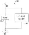
功率收集电路246可以被配置为从外部RF发射器接收RF能量,并从RF能量收集功率以为一个或多个电子部件供电或充电。例如,从RF能量收集的功率可以用于为气溶胶递送设备100的传感器供电,该传感器可以是或包括加速度计、陀螺仪、接近度传感器等。在另一个示例中,从RF能量收集的功率可以用于为气溶胶递送设备的显示器(例如,LED显示器)供电。The
图3更具体地示出了根据本公开的示例实现的图1和图2的控制主体102,其包括用于为至少一个电子部件302供电或充电的功率收集电路246。应注意,一个或多个电子部件可以被包括在气溶胶递送设备100的控制主体或料筒104中的任一个或两个中。如图3所示,功率收集电路246可以包括:天线304,被配置为从外部RF发射器接收RF能量;以及转换器306,被配置为从RF能量收集功率。3 shows the
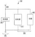
图4、图5和图6更具体地示出了根据本公开的示例实现的图3的控制主体102。根据一些示例实现,控制主体102的功率源212可以是可再充电功率源,诸如可充电锂离子电池(LiB)、薄膜固态电池(SSB)、或薄膜超级电容器,并且因此可以与任何类型的再充电技术组合,其中一些可以包括使用从RF能量收集的功率。因此,如图4所示,在一些示例实现中,至少一个电子部件可以包括功率源,并且功率收集电路246可以被配置为从RF能量收集功率以为功率源充电。4, 5, and 6 illustrate the
如图4中还示出的,功率源212可以连接到电负载402,电负载402包括控制主体的各种部件以形成电子电路,并且当控制主体与料筒104耦合时,电负载402还可以包括加热器222。更具体地,电负载可以包括控制部件208,控制部件208也可以与功率源耦合。在一些实现中,至少一个电子部件可以包括电负载。在一些实现中,从RF能量收集的功率可以用于独立于功率源212(例如,锂离子电池、固态电池或超级电容器)或与功率源212接合为各种电子部件供电。因此,在这些示例中的一些示例中,功率收集电路246可以被配置为从RF能量收集功率以为功率源充电,并且功率源可以被配置为为至少一个其他电子部件(诸如,显示器、或传感器、或加热器)供电。As also shown in FIG. 4 , the
如图5中所示,在一些示例实现中,功率收集电路246包括蓄电池502。在这些示例实现中,功率收集电路可以被配置为从RF能量收集功率以为蓄电池充电,蓄电池被配置为为至少一个电子部件302供电或充电。蓄电池可以是或包括合适的能量存储部件,诸如,可充电锂离子电池、可充电薄膜固态电池、可充电超级电容器等。在一些示例中,转换器306可以被配置为将RF能量转换为DC功率并将功率存储在蓄电池中,直到达到蓄电池的充电阈值。在已经实现蓄电池的充电阈值的实例中,蓄电池可以被配置为通过使用直流(DC)升压转换器电路来升高其输出电压电平。当电荷下降到低于充电阈值时,可以禁用电压输出。As shown in FIG. 5 , in some example implementations, the
如图5中还示出的,在一些示例中,功率收集电路246可以包括许多其他电子部件,诸如,放大器、模数(ADC)转换器、数模(DAC)转换器、电阻器、指示器等以形成电子电路。在一些示例中,蓄电池502可以被配置为通过运算放大器504(例如,反相或非反相运算放大器)放电,其中运算放大器可以被配置为放大和调节从蓄电池到至少一个电子部件302的放电电流。功率收集电路还可以包括可变电阻器506,其中蓄电池可以被配置为将电流通过电阻器放电到至少一个电子部件。电阻器可以具有可变电阻,并且由此电流可以具有可变安培数,其可以影响可变的瓦数。例如,电阻器可以是或包括三端电阻器,诸如电位计。这样,电阻器可以被配置为调节从蓄电池释放到至少一个电子部件的功率的电压或电流范围。在一些示例中,蓄电池的输出电压可以被设置为3.3伏特,并且可以通过使用可变电阻器将电压从1.8伏特调节到高达5.25伏特。As also shown in FIG. 5 , in some examples, the
功率收集电路246还可以包括指示器508(例如,可以包括有机发光二极管(LED)的LED 214),其被配置为在视觉上指示蓄电池502的电压电平。在一些示例中,指示器可以耦合到控制组件208并且包括在控制主体102中。在这些示例中,功率收集电路可以生成信号并将信号发送到控制部件,用于驱动指示器,其中信号可以对应于蓄电池的电压电平。The
如图6所示,在一些示例中,功率收集电路246可以包括被配置成从光能收集功率的光伏电池PC。在这些示例中,至少一个电子部件302可以从转换器306或光伏电池供电或充电,或者可以从转换器和光伏电池两者切换地供电或充电。在一些示例实现中,至少一个电子部件可以被配置为从转换器接收功率,并且仅在转换器已经放电至少阈值量之后切换到光伏电池。As shown in FIG. 6, in some examples, the
再次参照图2,除了控制主体102之外或代替控制主体102,料筒104可以包括功率收集电路248,其可以被配置成与控制主体的功率收集电路246相似并且起到与控制主体的功率收集电路246相似的功能,如上文参考图3-6所讨论的。例如,料筒可以包括功率收集电路,其被配置为从RF能量收集功率,用于为料筒以及一些实例中的控制主体的各种电子部件(诸如,加热器222、传感器、显示器、或其他合适的电子部件)供电或充电。在这些示例中,根据本文讨论的各种示例实现,功率收集电路可以被配置为从外部RF发射器接收RF能量,并且从RF能量收集功率以为各种电子部件供电或充电。Referring again to FIG. 2, in addition to or in place of the
图7示出了根据本公开的示例实现用于控制气溶胶递送设备的方法700的各种操作。气溶胶递送设备可以包括控制主体,控制主体与料筒耦合或可以与料筒耦合,以形成气溶胶递送设备。料筒可以配备有加热元件,加热元件被配置为活化和蒸发气溶胶前体组合物的组分。该方法可以包括通过天线从外部RF发射器接收RF能量,如框702所示。该方法还可以包括使用转换器从RF能量收集功率,用于为至少一个电子部件供电或充电,如框704所示。7 illustrates various operations implementing a
(多种)制品的前述使用描述可以通过微小修改应用于本文中所描述的各种示例实现,鉴于本文中所提供的更多公开内容所述微小修改对于所属领域的技术人员而言可以是明显的。然而,以上使用描述并不旨在限制制品的使用,而是提供以符合本公开的公开内容的所有必要需求。图1-7中所图示的或如上文以其它方式所描述的一种或多种制品中所示的元件中的任一种可以包含于根据本公开的气溶胶递送设备中。The foregoing description of use of the article(s) can be implemented with minor modifications applied to the various examples described herein, which minor modifications may be apparent to those skilled in the art in view of the further disclosure provided herein of. However, the above description of use is not intended to limit the use of the article of manufacture, but to provide all necessary requirements to comply with the disclosure of the present disclosure. Any of the elements illustrated in Figures 1-7 or shown in one or more articles of manufacture as otherwise described above may be included in an aerosol delivery device according to the present disclosure.
得益于前述描述和相关图式中所呈现的教示,公开内容涉及的所属领域的技术人员将了解本文中阐述的这个公开内容的许多修改和其它实施方案。因此,应理解,本公开不限于所公开的特定实施方案,且其修改和其它实施方案意图包含于所附权利要求书的范围内。此外,尽管前述描述和相关图式在元件和/或功能的某些示例组合的上下文中描述示例实现,但应了解,可以在不脱离所附权利要求书的范围的情况下,通过替代实施方案提供元件和/或功能的不同组合。就此而言,例如,还涵盖与上文明确描述的那些组合不同的元件和/或功能的组合,如同阐述于所附权利要求书中的一些中的一样。尽管本文中采用特定术语,但所述术语仅在通用意义和描述性意义上使用,而不用于局限性目的。Many modifications and other embodiments of the disclosure set forth herein will come to mind to one skilled in the art to which the disclosure pertains having the benefit of the teachings presented in the foregoing descriptions and the associated drawings. Therefore, it is to be understood that the present disclosure is not to be limited to the specific embodiments disclosed and that modifications and other embodiments thereof are intended to be included within the scope of the appended claims. Furthermore, while the foregoing description and associated drawings describe example implementations in the context of certain example combinations of elements and/or functions, it should be understood that alternative implementations may be employed without departing from the scope of the appended claims Different combinations of elements and/or functions are provided. In this regard, for example, different combinations of elements and/or functions than those expressly described above are also contemplated as set forth in some of the appended claims. Although specific terms are employed herein, these terms are used in a generic and descriptive sense only and not for purposes of limitation.
Claims (16)
Translated fromChineseApplications Claiming Priority (4)
| Application Number | Priority Date | Filing Date | Title |
|---|---|---|---|
| US15/205,903 | 2016-07-08 | ||
| US15/205,903US10231485B2 (en) | 2016-07-08 | 2016-07-08 | Radio frequency to direct current converter for an aerosol delivery device |
| PCT/IB2017/054021WO2018007938A1 (en) | 2016-07-08 | 2017-07-03 | Radio frequency to direct current converter for an aerosol delivery device |
| CN201780054762.1ACN109689142B (en) | 2016-07-08 | 2017-07-03 | Radio frequency to direct current converter for aerosol delivery device |
Related Parent Applications (1)
| Application Number | Title | Priority Date | Filing Date |
|---|---|---|---|
| CN201780054762.1ADivisionCN109689142B (en) | 2016-07-08 | 2017-07-03 | Radio frequency to direct current converter for aerosol delivery device |
Publications (2)
| Publication Number | Publication Date |
|---|---|
| CN115137097Atrue CN115137097A (en) | 2022-10-04 |
| CN115137097B CN115137097B (en) | 2025-07-29 |
Family
ID=59523200
Family Applications (2)
| Application Number | Title | Priority Date | Filing Date |
|---|---|---|---|
| CN201780054762.1AActiveCN109689142B (en) | 2016-07-08 | 2017-07-03 | Radio frequency to direct current converter for aerosol delivery device |
| CN202210539599.0AActiveCN115137097B (en) | 2016-07-08 | 2017-07-03 | RF to DC converter for aerosol delivery device |
Family Applications Before (1)
| Application Number | Title | Priority Date | Filing Date |
|---|---|---|---|
| CN201780054762.1AActiveCN109689142B (en) | 2016-07-08 | 2017-07-03 | Radio frequency to direct current converter for aerosol delivery device |
Country Status (9)
| Country | Link |
|---|---|
| US (1) | US10231485B2 (en) |
| EP (2) | EP3481474B1 (en) |
| JP (3) | JP7109006B2 (en) |
| KR (3) | KR102766269B1 (en) |
| CN (2) | CN109689142B (en) |
| CA (1) | CA3030097A1 (en) |
| PL (1) | PL3481474T3 (en) |
| RU (1) | RU2745104C2 (en) |
| WO (1) | WO2018007938A1 (en) |
Families Citing this family (27)
| Publication number | Priority date | Publication date | Assignee | Title |
|---|---|---|---|---|
| US10231485B2 (en)* | 2016-07-08 | 2019-03-19 | Rai Strategic Holdings, Inc. | Radio frequency to direct current converter for an aerosol delivery device |
| CA173126S (en)* | 2016-09-30 | 2019-02-14 | Fontem Holdings 1 Bv | Electronic vaping device |
| DE212017000292U1 (en)* | 2017-01-24 | 2019-09-17 | Japan Tobacco Inc. | inhalation device |
| TWI664922B (en)* | 2018-04-30 | 2019-07-11 | 黃庭輝 | Heating device |
| US10959459B2 (en) | 2018-05-16 | 2021-03-30 | Rai Strategic Holdings, Inc. | Voltage regulator for an aerosol delivery device |
| WO2020058146A1 (en)* | 2018-09-21 | 2020-03-26 | Koninklijke Philips N.V. | Radio frequency powered airway pressure support device |
| KR102167498B1 (en)* | 2018-10-23 | 2020-10-19 | 주식회사 이엠텍 | Microwave heating fine particle generator using wireless rf frequency |
| KR102178423B1 (en)* | 2018-11-09 | 2020-11-16 | 주식회사 이엠텍 | Microwave heating type fine particle generator |
| KR102214679B1 (en)* | 2018-12-26 | 2021-02-10 | 주식회사 이노아이티 | Microwave heating type fine particle generator |
| KR102214675B1 (en)* | 2018-12-26 | 2021-02-10 | 주식회사 이노아이티 | Microwave heating type fine particle generator |
| US11456480B2 (en)* | 2019-02-07 | 2022-09-27 | Rai Strategic Holdings, Inc. | Non-inverting amplifier circuit for an aerosol delivery device |
| US12239165B2 (en)* | 2019-03-11 | 2025-03-04 | Nicoventures Trading Limited | Aerosol provision device |
| CA3132765C (en)* | 2019-03-11 | 2023-12-05 | Nicoventures Trading Limited | Aerosol generating device |
| KR102389832B1 (en)* | 2019-06-18 | 2022-04-22 | 주식회사 케이티앤지 | Apparatus for generating aerosol by using microwave and method thereof |
| JP7458473B2 (en)* | 2019-07-08 | 2024-03-29 | イーエム-テック・カンパニー・リミテッド | Portable aerosol generator with sensing function for aerosol-forming substrate and method of operating the same |
| CA3152232A1 (en)* | 2019-09-03 | 2021-03-11 | Trudell Medical International | Medical device with energy harvesting system |
| US11631983B2 (en) | 2020-03-02 | 2023-04-18 | Rai Strategic Holdings, Inc. | Reusable shipping container with charging interface |
| JP6952851B1 (en)* | 2020-09-07 | 2021-10-27 | 日本たばこ産業株式会社 | Controller for aspirator |
| KR102608972B1 (en) | 2021-04-30 | 2023-12-01 | 주식회사 케이티앤지 | Aerosol generating device |
| GB202117825D0 (en)* | 2021-12-09 | 2022-01-26 | Nicoventures Trading Ltd | Charging an aerosol provision device |
| GB202117814D0 (en)* | 2021-12-09 | 2022-01-26 | Nicoventures Trading Ltd | Charging device having an antenna |
| GB202117822D0 (en)* | 2021-12-09 | 2022-01-26 | Nicoventures Trading Ltd | Control of use of extracted electrical power |
| GB202117815D0 (en)* | 2021-12-09 | 2022-01-26 | Nicoventures Trading Ltd | Charging device |
| GB202117818D0 (en)* | 2021-12-09 | 2022-01-26 | Nicoventures Trading Ltd | Radio frequency transmitter |
| CN120112187A (en) | 2022-10-14 | 2025-06-06 | 艾柔品牌公司 | Dispensing device with electromechanical feedback system and method of use |
| CN120322174A (en)* | 2022-12-12 | 2025-07-15 | 菲利普莫里斯生产公司 | Aerosol generating device with radio frequency energy harvesting system |
| WO2025014667A2 (en) | 2023-07-07 | 2025-01-16 | Airo Brands Inc. | A dispensing device with an electromechanical feedback system and methods of use |
Citations (8)
| Publication number | Priority date | Publication date | Assignee | Title |
|---|---|---|---|---|
| US20120133213A1 (en)* | 2010-11-24 | 2012-05-31 | Georgia-Pacific Consumer Products Lp | Apparatus and method for wirelessly powered dispensing |
| US20120160251A1 (en)* | 2010-12-27 | 2012-06-28 | Jeff Hammel | Electronic rechargeable smoking unit |
| US20130220315A1 (en)* | 2009-07-27 | 2013-08-29 | Fuma International Llc | Electronic vaporizer |
| US20140278258A1 (en)* | 2013-03-15 | 2014-09-18 | Altria Client Services Inc. | Accessory for electronic cigarette |
| CN104113224A (en)* | 2013-12-19 | 2014-10-22 | 西安电子科技大学 | Radio frequency energy acquisition circuit system |
| WO2015192336A1 (en)* | 2014-06-18 | 2015-12-23 | 吉瑞高新科技股份有限公司 | Battery assembly and electronic cigarette |
| US20160120221A1 (en)* | 2014-05-21 | 2016-05-05 | Philip Morris Products S.A. | Aerosol-generating system comprising a mesh susceptor |
| CN205263852U (en)* | 2015-11-27 | 2016-05-25 | 深圳市中远达智能科技有限公司 | Passive label circuit and electronic tags |
Family Cites Families (212)
| Publication number | Priority date | Publication date | Assignee | Title |
|---|---|---|---|---|
| US2057353A (en) | 1936-10-13 | Vaporizing unit fob therapeutic | ||
| US1771366A (en) | 1926-10-30 | 1930-07-22 | R W Cramer & Company Inc | Medicating apparatus |
| US2104266A (en) | 1935-09-23 | 1938-01-04 | William J Mccormick | Means for the production and inhalation of tobacco fumes |
| US3200819A (en) | 1963-04-17 | 1965-08-17 | Herbert A Gilbert | Smokeless non-tobacco cigarette |
| US4284089A (en) | 1978-10-02 | 1981-08-18 | Ray Jon P | Simulated smoking device |
| US4303083A (en) | 1980-10-10 | 1981-12-01 | Burruss Jr Robert P | Device for evaporation and inhalation of volatile compounds and medications |
| SE8405479D0 (en) | 1984-11-01 | 1984-11-01 | Nilsson Sven Erik | WANT TO ADMINISTER VOCABULARY, PHYSIOLOGY, ACTIVE SUBJECTS AND DEVICE FOR THIS |
| US4735217A (en) | 1986-08-21 | 1988-04-05 | The Procter & Gamble Company | Dosing device to provide vaporized medicament to the lungs as a fine aerosol |
| GB8713645D0 (en) | 1987-06-11 | 1987-07-15 | Imp Tobacco Ltd | Smoking device |
| US5019122A (en) | 1987-08-21 | 1991-05-28 | R. J. Reynolds Tobacco Company | Smoking article with an enclosed heat conductive capsule containing an aerosol forming substance |
| US4947875A (en) | 1988-09-08 | 1990-08-14 | R. J. Reynolds Tobacco Company | Flavor delivery articles utilizing electrical energy |
| US4947874A (en) | 1988-09-08 | 1990-08-14 | R. J. Reynolds Tobacco Company | Smoking articles utilizing electrical energy |
| US4922901A (en) | 1988-09-08 | 1990-05-08 | R. J. Reynolds Tobacco Company | Drug delivery articles utilizing electrical energy |
| US4986286A (en) | 1989-05-02 | 1991-01-22 | R. J. Reynolds Tobacco Company | Tobacco treatment process |
| US4945931A (en) | 1989-07-14 | 1990-08-07 | Brown & Williamson Tobacco Corporation | Simulated smoking device |
| US5154192A (en) | 1989-07-18 | 1992-10-13 | Philip Morris Incorporated | Thermal indicators for smoking articles and the method of application of the thermal indicators to the smoking article |
| US5408574A (en) | 1989-12-01 | 1995-04-18 | Philip Morris Incorporated | Flat ceramic heater having discrete heating zones |
| US5144962A (en)* | 1989-12-01 | 1992-09-08 | Philip Morris Incorporated | Flavor-delivery article |
| US5060671A (en) | 1989-12-01 | 1991-10-29 | Philip Morris Incorporated | Flavor generating article |
| US5093894A (en) | 1989-12-01 | 1992-03-03 | Philip Morris Incorporated | Electrically-powered linear heating element |
| US5042510A (en) | 1990-01-08 | 1991-08-27 | Curtiss Philip F | Simulated cigarette |
| US5505214A (en) | 1991-03-11 | 1996-04-09 | Philip Morris Incorporated | Electrical smoking article and method for making same |
| US5726421A (en) | 1991-03-11 | 1998-03-10 | Philip Morris Incorporated | Protective and cigarette ejection system for an electrical smoking system |
| US5249586A (en) | 1991-03-11 | 1993-10-05 | Philip Morris Incorporated | Electrical smoking |
| US5530225A (en) | 1991-03-11 | 1996-06-25 | Philip Morris Incorporated | Interdigitated cylindrical heater for use in an electrical smoking article |
| US5261424A (en) | 1991-05-31 | 1993-11-16 | Philip Morris Incorporated | Control device for flavor-generating article |
| IL104930A (en) | 1992-03-25 | 1995-12-31 | Reynolds Tobacco Co R | Components for smoking articles and their manufacture |
| US5353813A (en) | 1992-08-19 | 1994-10-11 | Philip Morris Incorporated | Reinforced carbon heater with discrete heating zones |
| US5322075A (en) | 1992-09-10 | 1994-06-21 | Philip Morris Incorporated | Heater for an electric flavor-generating article |
| US5498850A (en) | 1992-09-11 | 1996-03-12 | Philip Morris Incorporated | Semiconductor electrical heater and method for making same |
| US5369723A (en) | 1992-09-11 | 1994-11-29 | Philip Morris Incorporated | Tobacco flavor unit for electrical smoking article comprising fibrous mat |
| US5441060A (en) | 1993-02-08 | 1995-08-15 | Duke University | Dry powder delivery system |
| US5372148A (en) | 1993-02-24 | 1994-12-13 | Philip Morris Incorporated | Method and apparatus for controlling the supply of energy to a heating load in a smoking article |
| US5468936A (en) | 1993-03-23 | 1995-11-21 | Philip Morris Incorporated | Heater having a multiple-layer ceramic substrate and method of fabrication |
| US5666977A (en) | 1993-06-10 | 1997-09-16 | Philip Morris Incorporated | Electrical smoking article using liquid tobacco flavor medium delivery system |
| DK0706352T3 (en) | 1993-06-29 | 2002-07-15 | Ponwell Entpr Ltd | Dispenser |
| US5388574A (en) | 1993-07-29 | 1995-02-14 | Ingebrethsen; Bradley J. | Aerosol delivery article |
| CH686872A5 (en) | 1993-08-09 | 1996-07-31 | Disetronic Ag | Medical Inhalationsgeraet. |
| DE4328243C1 (en) | 1993-08-19 | 1995-03-09 | Sven Mielordt | Smoke or inhalation device |
| IE72523B1 (en) | 1994-03-10 | 1997-04-23 | Elan Med Tech | Nicotine oral delivery device |
| US5649554A (en) | 1995-10-16 | 1997-07-22 | Philip Morris Incorporated | Electrical lighter with a rotatable tobacco supply |
| US5564442A (en) | 1995-11-22 | 1996-10-15 | Angus Collingwood MacDonald | Battery powered nicotine vaporizer |
| US5743251A (en) | 1996-05-15 | 1998-04-28 | Philip Morris Incorporated | Aerosol and a method and apparatus for generating an aerosol |
| DE69724559T2 (en) | 1996-06-17 | 2004-07-15 | Japan Tobacco Inc. | FLAVORED ARTICLE |
| US6125853A (en) | 1996-06-17 | 2000-10-03 | Japan Tobacco, Inc. | Flavor generation device |
| US6089857A (en) | 1996-06-21 | 2000-07-18 | Japan Tobacco, Inc. | Heater for generating flavor and flavor generation appliance |
| US5934289A (en) | 1996-10-22 | 1999-08-10 | Philip Morris Incorporated | Electronic smoking system |
| US6040560A (en) | 1996-10-22 | 2000-03-21 | Philip Morris Incorporated | Power controller and method of operating an electrical smoking system |
| US5878752A (en) | 1996-11-25 | 1999-03-09 | Philip Morris Incorporated | Method and apparatus for using, cleaning, and maintaining electrical heat sources and lighters useful in smoking systems and other apparatuses |
| US5865186A (en) | 1997-05-21 | 1999-02-02 | Volsey, Ii; Jack J | Simulated heated cigarette |
| KR100289448B1 (en) | 1997-07-23 | 2001-05-02 | 미즈노 마사루 | Flavor generator |
| US5954979A (en) | 1997-10-16 | 1999-09-21 | Philip Morris Incorporated | Heater fixture of an electrical smoking system |
| US5967148A (en) | 1997-10-16 | 1999-10-19 | Philip Morris Incorporated | Lighter actuation system |
| DE1149602T1 (en) | 1997-11-19 | 2002-04-04 | Microflow Engineering S.A., Neuenburg/Neuchatel | Spray device for an inhaler suitable for respiratory therapy |
| CN1044314C (en) | 1997-12-01 | 1999-07-28 | 蒲邯名 | Healthy cigarette |
| US6164287A (en) | 1998-06-10 | 2000-12-26 | R. J. Reynolds Tobacco Company | Smoking method |
| US6095153A (en) | 1998-06-19 | 2000-08-01 | Kessler; Stephen B. | Vaporization of volatile materials |
| US6234167B1 (en) | 1998-10-14 | 2001-05-22 | Chrysalis Technologies, Incorporated | Aerosol generator and methods of making and using an aerosol generator |
| US6053176A (en) | 1999-02-23 | 2000-04-25 | Philip Morris Incorporated | Heater and method for efficiently generating an aerosol from an indexing substrate |
| US6196218B1 (en) | 1999-02-24 | 2001-03-06 | Ponwell Enterprises Ltd | Piezo inhaler |
| CA2385324C (en) | 1999-09-22 | 2008-03-25 | Miodrag Oljaca | Liquid atomization methods and devices |
| CA2403378C (en) | 2000-03-23 | 2010-01-05 | Philip Morris Products Inc. | Electrical smoking system and method |
| US7559324B2 (en) | 2000-06-21 | 2009-07-14 | Fisher & Paykel Healthcare Limited | Conduit with heated wick |
| EP1247447B1 (en) | 2001-04-05 | 2004-09-15 | C.T.R., Consultoria, Técnica e Representaçoes Lda | Device for vaporising fluids, particularly insecticides and/or perfumes |
| EP2295619B1 (en) | 2001-01-26 | 2014-04-23 | MEMC Electronic Materials, Inc. | Process for producing Low Defect Density Silicon Having a Vacancy-Dominated Core Substantially Free of Oxidation Induced Stacking Faults |
| US6598607B2 (en) | 2001-10-24 | 2003-07-29 | Brown & Williamson Tobacco Corporation | Non-combustible smoking device and fuel element |
| AU2002357599A1 (en) | 2001-12-28 | 2003-07-24 | Japan Tobacco Inc. | Smoking implement |
| US6772756B2 (en) | 2002-02-09 | 2004-08-10 | Advanced Inhalation Revolutions Inc. | Method and system for vaporization of a substance |
| US6615840B1 (en) | 2002-02-15 | 2003-09-09 | Philip Morris Incorporated | Electrical smoking system and method |
| AU2003222642A1 (en) | 2002-05-10 | 2003-11-11 | Chrysalis Technologies Incorporated | Aerosol generator for drug formulation and methods of generating aerosol |
| US6803545B2 (en) | 2002-06-05 | 2004-10-12 | Philip Morris Incorporated | Electrically heated smoking system and methods for supplying electrical power from a lithium ion power source |
| CN1700934B (en) | 2002-09-06 | 2011-08-03 | 菲利普莫里斯美国公司 | Liquid aerosol preparation and aerosol generating device and method for preparing aerosol |
| CA2502171C (en) | 2002-10-31 | 2013-01-15 | Philip Morris Products S.A. | Electrically heated cigarette including controlled-release flavoring |
| US6810883B2 (en) | 2002-11-08 | 2004-11-02 | Philip Morris Usa Inc. | Electrically heated cigarette smoking system with internal manifolding for puff detection |
| CN100381082C (en) | 2003-03-14 | 2008-04-16 | 韩力 | Non-combustible electronic atomized cigarette |
| CN100381083C (en) | 2003-04-29 | 2008-04-16 | 韩力 | Non-combustible electronic spray cigarette |
| US7293565B2 (en) | 2003-06-30 | 2007-11-13 | Philip Morris Usa Inc. | Electrically heated cigarette smoking system |
| JP2005034021A (en) | 2003-07-17 | 2005-02-10 | Seiko Epson Corp | Electronic Cigarette |
| US7084605B2 (en) | 2003-10-29 | 2006-08-01 | University Of Pittsburgh | Energy harvesting circuit |
| CN2719043Y (en) | 2004-04-14 | 2005-08-24 | 韩力 | Atomized electronic cigarette |
| US7775459B2 (en) | 2004-06-17 | 2010-08-17 | S.C. Johnson & Son, Inc. | Liquid atomizing device with reduced settling of atomized liquid droplets |
| US20060016453A1 (en) | 2004-07-22 | 2006-01-26 | Kim In Y | Cigarette substitute device |
| US7513253B2 (en) | 2004-08-02 | 2009-04-07 | Canon Kabushiki Kaisha | Liquid medication cartridge and inhaler using the cartridge |
| DE102004061883A1 (en) | 2004-12-22 | 2006-07-06 | Vishay Electronic Gmbh | Heating device for inhalation device, inhaler and heating method |
| DE102005034169B4 (en) | 2005-07-21 | 2008-05-29 | NjoyNic Ltd., Glen Parva | Smoke-free cigarette |
| US20070215167A1 (en) | 2006-03-16 | 2007-09-20 | Evon Llewellyn Crooks | Smoking article |
| US20070102013A1 (en) | 2005-09-30 | 2007-05-10 | Philip Morris Usa Inc. | Electrical smoking system |
| US20070074734A1 (en) | 2005-09-30 | 2007-04-05 | Philip Morris Usa Inc. | Smokeless cigarette system |
| KR20080064986A (en)* | 2005-10-21 | 2008-07-10 | 더 리젠트스 오브 더 유니버시티 오브 콜로라도 | System and method for receiving and managing power in wireless devices |
| WO2007078273A1 (en) | 2005-12-22 | 2007-07-12 | Augite Incorporation | No-tar electronic smoking utensils |
| FR2895644B1 (en) | 2006-01-03 | 2008-05-16 | Didier Gerard Martzel | SUBSTITUTE OF CIGARETTE |
| DE102006004484A1 (en) | 2006-01-29 | 2007-08-09 | Karsten Schmidt | Re-usable part for smoke-free cigarette, has filament preheated by attaching filter, where filament is brought to operating temperature, when pulling on entire construction of cigarette |
| CN201067079Y (en) | 2006-05-16 | 2008-06-04 | 韩力 | Simulated aerosol inhaler |
| JP4895388B2 (en) | 2006-07-25 | 2012-03-14 | キヤノン株式会社 | Drug delivery device |
| US7734159B2 (en) | 2006-08-31 | 2010-06-08 | S.C. Johnson & Son, Inc. | Dispersion device for dispersing multiple volatile materials |
| DE102006041042B4 (en) | 2006-09-01 | 2009-06-25 | W + S Wagner + Söhne Mess- und Informationstechnik GmbH & Co.KG | Device for dispensing a nicotine-containing aerosol |
| DE102007026979A1 (en) | 2006-10-06 | 2008-04-10 | Friedrich Siller | inhalator |
| US7726320B2 (en) | 2006-10-18 | 2010-06-01 | R. J. Reynolds Tobacco Company | Tobacco-containing smoking article |
| EP2083642A4 (en) | 2006-11-06 | 2013-02-20 | Rock Sci Intellectual Llc | Mechanically regulated vaporization pipe |
| CN200966824Y (en) | 2006-11-10 | 2007-10-31 | 韩力 | Inhalation atomizing device |
| CN100536951C (en) | 2006-11-11 | 2009-09-09 | 达福堡国际有限公司 | Intrapulmonary administration device |
| CN200997909Y (en) | 2006-12-15 | 2008-01-02 | 王玉民 | Disposable electric purified cigarette |
| US7845359B2 (en) | 2007-03-22 | 2010-12-07 | Pierre Denain | Artificial smoke cigarette |
| US20080257367A1 (en) | 2007-04-23 | 2008-10-23 | Greg Paterno | Electronic evaporable substance delivery device and method |
| EP1989946A1 (en) | 2007-05-11 | 2008-11-12 | Rauchless Inc. | Smoking device, charging means and method of using it |
| US8115448B2 (en)* | 2007-06-01 | 2012-02-14 | Michael Sasha John | Systems and methods for wireless power |
| EP2162025B1 (en) | 2007-06-25 | 2014-06-25 | Kind Consumer Limited | A simulated cigarette device |
| CN100593982C (en) | 2007-09-07 | 2010-03-17 | 中国科学院理化技术研究所 | Electronic cigarette with nanoscale ultra-fine space heating atomization function |
| US8123082B2 (en) | 2008-01-22 | 2012-02-28 | McNeil-AB | Hand-held dispensing device |
| ES2706326T3 (en) | 2008-02-29 | 2019-03-28 | Yunqiang Xiu | Electronic simulated cigarette and smoking equipment comprising said electronic simulated cigarette |
| EP2100525A1 (en) | 2008-03-14 | 2009-09-16 | Philip Morris Products S.A. | Electrically heated aerosol generating system and method |
| EP2110034A1 (en) | 2008-04-17 | 2009-10-21 | Philip Morris Products S.A. | An electrically heated smoking system |
| RU2360583C1 (en) | 2008-04-28 | 2009-07-10 | Владимир Николаевич Урцев | Tobacco pipe for smokeless smoking |
| EP2113178A1 (en) | 2008-04-30 | 2009-11-04 | Philip Morris Products S.A. | An electrically heated smoking system having a liquid storage portion |
| US20090283103A1 (en) | 2008-05-13 | 2009-11-19 | Nielsen Michael D | Electronic vaporizing devices and docking stations |
| CN202197836U (en) | 2008-06-27 | 2012-04-25 | 马斯·伯纳德 | alternative to cigarettes |
| EP2143346A1 (en) | 2008-07-08 | 2010-01-13 | Philip Morris Products S.A. | A flow sensor system |
| WO2010009469A2 (en) | 2008-07-18 | 2010-01-21 | Peckerar Martin C | Thin flexible rechargeable electrochemical energy cell and method of fabrication |
| AT507187B1 (en) | 2008-10-23 | 2010-03-15 | Helmut Dr Buchberger | INHALER |
| CA2641869A1 (en) | 2008-11-06 | 2010-05-06 | Hao Ran Xia | Environmental friendly, non-combustible, atomizing electronic cigarette having the function of a cigarette substitute |
| US20110101789A1 (en) | 2008-12-01 | 2011-05-05 | Salter Jr Thomas Steven | Rf power harvesting circuit |
| EP2201850A1 (en) | 2008-12-24 | 2010-06-30 | Philip Morris Products S.A. | An article including identification information for use in an electrically heated smoking system |
| CN201379072Y (en) | 2009-02-11 | 2010-01-13 | 韩力 | An improved atomized electronic cigarette |
| CN101518361B (en) | 2009-03-24 | 2010-10-06 | 北京格林世界科技发展有限公司 | High-simulation electronic cigarette |
| US8803474B2 (en)* | 2009-03-25 | 2014-08-12 | Qualcomm Incorporated | Optimization of wireless power devices |
| CN201683029U (en) | 2009-04-15 | 2010-12-29 | 中国科学院理化技术研究所 | Heating atomization electronic cigarette adopting capacitor for power supply |
| GB2469850A (en) | 2009-04-30 | 2010-11-03 | British American Tobacco Co | Volatilization device |
| EP2253233A1 (en) | 2009-05-21 | 2010-11-24 | Philip Morris Products S.A. | An electrically heated smoking system |
| CN101606758B (en) | 2009-07-14 | 2011-04-13 | 方晓林 | Electronic cigarette |
| KR20110008374A (en)* | 2009-07-20 | 2011-01-27 | 김포대학산학협력단 | RF energy harvesting device |
| ITNA20090023U1 (en) | 2009-07-21 | 2011-01-22 | Rml S R L | ELECTRONIC CIGARETTE WITH ATOMISER INCORPORATED IN THE FAILED FILTER. |
| DE202009010400U1 (en) | 2009-07-31 | 2009-11-12 | Asch, Werner, Dipl.-Biol. | Control and control of electronic inhalation smoke machines |
| WO2011022431A1 (en) | 2009-08-17 | 2011-02-24 | Chong Corporation | Vaporized tobacco product and methods of use |
| US9254002B2 (en) | 2009-08-17 | 2016-02-09 | Chong Corporation | Tobacco solution for vaporized inhalation |
| MX344758B (en) | 2009-10-09 | 2017-01-05 | Philip Morris Products Sa | Aerosol generator including multi-component wick. |
| EP2319334A1 (en) | 2009-10-27 | 2011-05-11 | Philip Morris Products S.A. | A smoking system having a liquid storage portion |
| EP2316286A1 (en) | 2009-10-29 | 2011-05-04 | Philip Morris Products S.A. | An electrically heated smoking system with improved heater |
| EP2327318A1 (en) | 2009-11-27 | 2011-06-01 | Philip Morris Products S.A. | An electrically heated smoking system with internal or external heater |
| EP2340730A1 (en) | 2009-12-30 | 2011-07-06 | Philip Morris Products S.A. | A shaped heater for an aerosol generating system |
| EP2340729A1 (en) | 2009-12-30 | 2011-07-06 | Philip Morris Products S.A. | An improved heater for an electrically heated aerosol generating system |
| US9439455B2 (en) | 2010-04-30 | 2016-09-13 | Fontem Holdings 4 B.V. | Electronic smoking device |
| US20120042885A1 (en) | 2010-08-19 | 2012-02-23 | James Richard Stone | Segmented smoking article with monolithic substrate |
| US10159278B2 (en) | 2010-05-15 | 2018-12-25 | Rai Strategic Holdings, Inc. | Assembly directed airflow |
| US8314591B2 (en) | 2010-05-15 | 2012-11-20 | Nathan Andrew Terry | Charging case for a personal vaporizing inhaler |
| US9259035B2 (en) | 2010-05-15 | 2016-02-16 | R. J. Reynolds Tobacco Company | Solderless personal vaporizing inhaler |
| JP2012018098A (en)* | 2010-07-08 | 2012-01-26 | Seiko Instruments Inc | Portable electronic apparatus with charging function |
| SMT202000393T1 (en) | 2010-08-24 | 2020-09-10 | Jt Int Sa | Inhalation device including substance usage controls |
| US8499766B1 (en) | 2010-09-15 | 2013-08-06 | Kyle D. Newton | Electronic cigarette with function illuminator |
| WO2012065310A1 (en) | 2010-11-19 | 2012-05-24 | Liu Qiuming | Electronic cigarette, electronic cigarette flare and atomizer thereof |
| KR20120058138A (en) | 2010-11-29 | 2012-06-07 | 삼성전자주식회사 | Micro heater and micro heater array |
| EP2460423A1 (en) | 2010-12-03 | 2012-06-06 | Philip Morris Products S.A. | An electrically heated aerosol generating system having improved heater control |
| EP2460424A1 (en) | 2010-12-03 | 2012-06-06 | Philip Morris Products S.A. | An aerosol generating system with leakage prevention |
| EP2468118A1 (en) | 2010-12-24 | 2012-06-27 | Philip Morris Products S.A. | An aerosol generating system with means for disabling a consumable |
| WO2012100523A1 (en) | 2011-01-27 | 2012-08-02 | Tu Martin | Multi-functional inhalation type electronic smoke generator with memory device |
| US20120231464A1 (en) | 2011-03-10 | 2012-09-13 | Instrument Technology Research Center, National Applied Research Laboratories | Heatable Droplet Device |
| US20120318882A1 (en) | 2011-06-16 | 2012-12-20 | Vapor Corp. | Vapor delivery devices |
| US8528569B1 (en) | 2011-06-28 | 2013-09-10 | Kyle D. Newton | Electronic cigarette with liquid reservoir |
| CN102349699B (en) | 2011-07-04 | 2013-07-03 | 郑俊祥 | Preparation method for electronic cigarette liquid |
| US9078473B2 (en) | 2011-08-09 | 2015-07-14 | R.J. Reynolds Tobacco Company | Smoking articles and use thereof for yielding inhalation materials |
| US9351522B2 (en) | 2011-09-29 | 2016-05-31 | Robert Safari | Cartomizer e-cigarette |
| US9205220B2 (en) | 2011-09-30 | 2015-12-08 | Carefusion 207, Inc. | Fluted heater wire |
| US8646461B2 (en)* | 2011-12-14 | 2014-02-11 | Sentiens, Llc | Device and method for simulating chemosensation of smoking |
| MY154105A (en) | 2011-12-15 | 2015-04-30 | Foo Kit Seng | An electronic vaporisation cigarette |
| US20130180553A1 (en) | 2012-01-12 | 2013-07-18 | Meiko Maschinenbau Gmbh & Co. Kg | Dishwasher |
| US9854839B2 (en) | 2012-01-31 | 2018-01-02 | Altria Client Services Llc | Electronic vaping device and method |
| WO2013138384A2 (en) | 2012-03-12 | 2013-09-19 | Uptoke Llc | Electronic vaporizing device and methods for use |
| KR20140063532A (en) | 2012-03-23 | 2014-05-27 | 엔조이, 인코포레이티드 | Electronic cigarette configured to simulate the natural burn of a traditional cigarette |
| US20130255702A1 (en) | 2012-03-28 | 2013-10-03 | R.J. Reynolds Tobacco Company | Smoking article incorporating a conductive substrate |
| US20130340775A1 (en) | 2012-04-25 | 2013-12-26 | Bernard Juster | Application development for a network with an electronic cigarette |
| US11517042B2 (en) | 2012-04-25 | 2022-12-06 | Altria Client Services Llc | Digital marketing applications for electronic cigarette users |
| US10004259B2 (en) | 2012-06-28 | 2018-06-26 | Rai Strategic Holdings, Inc. | Reservoir and heater system for controllable delivery of multiple aerosolizable materials in an electronic smoking article |
| US8881737B2 (en) | 2012-09-04 | 2014-11-11 | R.J. Reynolds Tobacco Company | Electronic smoking article comprising one or more microheaters |
| US8910639B2 (en) | 2012-09-05 | 2014-12-16 | R. J. Reynolds Tobacco Company | Single-use connector and cartridge for a smoking article and related method |
| CN103960781A (en) | 2013-09-29 | 2014-08-06 | 深圳市麦克韦尔科技有限公司 | Electronic cigarette |
| US10117460B2 (en) | 2012-10-08 | 2018-11-06 | Rai Strategic Holdings, Inc. | Electronic smoking article and associated method |
| US9854841B2 (en)* | 2012-10-08 | 2018-01-02 | Rai Strategic Holdings, Inc. | Electronic smoking article and associated method |
| US10058122B2 (en) | 2012-10-25 | 2018-08-28 | Matthew Steingraber | Electronic cigarette |
| CA2890204C (en)* | 2012-11-28 | 2022-04-05 | E-Nicotine Technology, Inc. | Methods and devices for compound delivery |
| US9210738B2 (en) | 2012-12-07 | 2015-12-08 | R.J. Reynolds Tobacco Company | Apparatus and method for winding a substantially continuous heating element about a substantially continuous wick |
| US20140174459A1 (en)* | 2012-12-21 | 2014-06-26 | Vapor Innovations, LLC | Smart Electronic Cigarette |
| US9735835B2 (en)* | 2012-12-28 | 2017-08-15 | Avago Technologies General Ip (Singapore) Pte. Ltd. | Power transfer architecture with charging history |
| US8910640B2 (en)* | 2013-01-30 | 2014-12-16 | R.J. Reynolds Tobacco Company | Wick suitable for use in an electronic smoking article |
| CN104026742A (en)* | 2013-03-05 | 2014-09-10 | 向智勇 | Heating control method and device for electronic cigarette |
| US10031183B2 (en) | 2013-03-07 | 2018-07-24 | Rai Strategic Holdings, Inc. | Spent cartridge detection method and system for an electronic smoking article |
| US20140261486A1 (en) | 2013-03-12 | 2014-09-18 | R.J. Reynolds Tobacco Company | Electronic smoking article having a vapor-enhancing apparatus and associated method |
| US20140261487A1 (en) | 2013-03-14 | 2014-09-18 | R. J. Reynolds Tobacco Company | Electronic smoking article with improved storage and transport of aerosol precursor compositions |
| US9277770B2 (en) | 2013-03-14 | 2016-03-08 | R. J. Reynolds Tobacco Company | Atomizer for an aerosol delivery device formed from a continuously extending wire and related input, cartridge, and method |
| US9423152B2 (en)* | 2013-03-15 | 2016-08-23 | R. J. Reynolds Tobacco Company | Heating control arrangement for an electronic smoking article and associated system and method |
| SG11201507442TA (en)* | 2013-03-15 | 2015-10-29 | Philip Morris Products Sa | An aerosol-generating system with a replacable mouthpiece cover |
| US9220302B2 (en) | 2013-03-15 | 2015-12-29 | R.J. Reynolds Tobacco Company | Cartridge for an aerosol delivery device and method for assembling a cartridge for a smoking article |
| US9609893B2 (en) | 2013-03-15 | 2017-04-04 | Rai Strategic Holdings, Inc. | Cartridge and control body of an aerosol delivery device including anti-rotation mechanism and related method |
| US9491974B2 (en) | 2013-03-15 | 2016-11-15 | Rai Strategic Holdings, Inc. | Heating elements formed from a sheet of a material and inputs and methods for the production of atomizers |
| GB2514758B (en) | 2013-03-26 | 2015-06-24 | Kind Consumer Ltd | A Pressurised Refill Canister with an Outlet Valve |
| CN105263345A (en) | 2013-05-06 | 2016-01-20 | 派克斯实验公司 | Nicotine salt formulations for aerosol devices and methods thereof |
| US10004262B2 (en)* | 2013-06-26 | 2018-06-26 | Huizhou Kimree Technology Co., Ltd. Shenzhen Branch | Electronic cigarette and method for supplying constant power therein |
| UA122320C2 (en) | 2013-07-19 | 2020-10-26 | Олтріа Клайєнт Сервісиз Ллк | Liquid aerosol formulation of an electronic smoking article |
| US10251422B2 (en) | 2013-07-22 | 2019-04-09 | Altria Client Services Llc | Electronic smoking article |
| US20150216232A1 (en) | 2014-02-03 | 2015-08-06 | R.J. Reynolds Tobacco Company | Aerosol Delivery Device Comprising Multiple Outer Bodies and Related Assembly Method |
| US9973367B2 (en)* | 2014-02-11 | 2018-05-15 | University Of Washington | Apparatuses, systems, and methods for communicating using MIMO and spread spectrum coding in backscatter of ambient signals |
| US20150272222A1 (en)* | 2014-03-25 | 2015-10-01 | Nicotech, LLC | Inhalation sensor for alternative nicotine/thc delivery device |
| CN106413443B (en)* | 2014-06-18 | 2019-06-28 | 吉瑞高新科技股份有限公司 | Battery component and electronic cigarette |
| EP3183797B1 (en)* | 2014-08-19 | 2020-10-07 | California Institute of Technology | Wireless power transfer |
| RU2564611C1 (en)* | 2014-08-27 | 2015-10-10 | Общество с ограниченной ответственностью "Качество Жизни" | Electronic inhaler |
| CN104886780A (en)* | 2015-05-14 | 2015-09-09 | 深圳思格雷科技有限公司 | Electronic cigarette with detection device and detection method |
| CN204667224U (en)* | 2015-06-15 | 2015-09-23 | 彭玉刚 | A kind of electronic cigarette Auto-matching temperature control circuit |
| CN204861167U (en)* | 2015-06-17 | 2015-12-16 | 深圳市新宜康科技有限公司 | Electron smog temperature -control circuit and controllable temperature electron smog core |
| CN105011375B (en)* | 2015-07-21 | 2017-12-15 | 昆山祥维电子科技有限公司 | A kind of electronic cigarette that is atomized silk resistance and can automatically control |
| CN105186719B (en)* | 2015-10-21 | 2018-02-09 | 浙江大学 | Wireless structural health monitoring node based on RF energy collection |
| US11291252B2 (en) | 2015-12-18 | 2022-04-05 | Rai Strategic Holdings, Inc. | Proximity sensing for an aerosol delivery device |
| US10079515B2 (en)* | 2016-12-12 | 2018-09-18 | Energous Corporation | Near-field RF charging pad with multi-band antenna element with adaptive loading to efficiently charge an electronic device at any position on the pad |
| US10945462B2 (en)* | 2016-04-12 | 2021-03-16 | Rai Strategic Holdings, Inc. | Detachable power source for an aerosol delivery device |
| US10231485B2 (en)* | 2016-07-08 | 2019-03-19 | Rai Strategic Holdings, Inc. | Radio frequency to direct current converter for an aerosol delivery device |
- 2016
- 2016-07-08USUS15/205,903patent/US10231485B2/enactiveActive
- 2017
- 2017-07-03WOPCT/IB2017/054021patent/WO2018007938A1/ennot_activeCeased
- 2017-07-03JPJP2019500516Apatent/JP7109006B2/enactiveActive
- 2017-07-03EPEP17748929.1Apatent/EP3481474B1/enactiveActive
- 2017-07-03EPEP22199292.8Apatent/EP4159066A1/enactivePending
- 2017-07-03RURU2019103017Apatent/RU2745104C2/enactive
- 2017-07-03CACA3030097Apatent/CA3030097A1/enactivePending
- 2017-07-03PLPL17748929.1Tpatent/PL3481474T3/enunknown
- 2017-07-03KRKR1020237044596Apatent/KR102766269B1/enactiveActive
- 2017-07-03CNCN201780054762.1Apatent/CN109689142B/enactiveActive
- 2017-07-03KRKR1020197003810Apatent/KR102516977B1/enactiveActive
- 2017-07-03CNCN202210539599.0Apatent/CN115137097B/enactiveActive
- 2017-07-03KRKR1020237010673Apatent/KR102619028B1/enactiveActive
- 2022
- 2022-07-06JPJP2022108850Apatent/JP2022133403A/enactivePending
- 2024
- 2024-06-12JPJP2024094901Apatent/JP2024119932A/enactivePending
Patent Citations (8)
| Publication number | Priority date | Publication date | Assignee | Title |
|---|---|---|---|---|
| US20130220315A1 (en)* | 2009-07-27 | 2013-08-29 | Fuma International Llc | Electronic vaporizer |
| US20120133213A1 (en)* | 2010-11-24 | 2012-05-31 | Georgia-Pacific Consumer Products Lp | Apparatus and method for wirelessly powered dispensing |
| US20120160251A1 (en)* | 2010-12-27 | 2012-06-28 | Jeff Hammel | Electronic rechargeable smoking unit |
| US20140278258A1 (en)* | 2013-03-15 | 2014-09-18 | Altria Client Services Inc. | Accessory for electronic cigarette |
| CN104113224A (en)* | 2013-12-19 | 2014-10-22 | 西安电子科技大学 | Radio frequency energy acquisition circuit system |
| US20160120221A1 (en)* | 2014-05-21 | 2016-05-05 | Philip Morris Products S.A. | Aerosol-generating system comprising a mesh susceptor |
| WO2015192336A1 (en)* | 2014-06-18 | 2015-12-23 | 吉瑞高新科技股份有限公司 | Battery assembly and electronic cigarette |
| CN205263852U (en)* | 2015-11-27 | 2016-05-25 | 深圳市中远达智能科技有限公司 | Passive label circuit and electronic tags |
Also Published As
| Publication number | Publication date |
|---|---|
| KR102516977B1 (en) | 2023-04-04 |
| WO2018007938A1 (en) | 2018-01-11 |
| KR20190039406A (en) | 2019-04-11 |
| US20180007969A1 (en) | 2018-01-11 |
| EP4159066A1 (en) | 2023-04-05 |
| RU2019103017A (en) | 2020-08-10 |
| JP2019525747A (en) | 2019-09-12 |
| CN109689142B (en) | 2022-06-07 |
| CN109689142A (en) | 2019-04-26 |
| RU2745104C2 (en) | 2021-03-19 |
| KR20230047510A (en) | 2023-04-07 |
| JP7109006B2 (en) | 2022-07-29 |
| EP3481474B1 (en) | 2022-10-05 |
| JP2024119932A (en) | 2024-09-03 |
| PL3481474T3 (en) | 2023-01-23 |
| KR20240007291A (en) | 2024-01-16 |
| CN115137097B (en) | 2025-07-29 |
| US10231485B2 (en) | 2019-03-19 |
| KR102619028B1 (en) | 2023-12-29 |
| CA3030097A1 (en) | 2018-01-11 |
| KR102766269B1 (en) | 2025-02-11 |
| RU2019103017A3 (en) | 2020-09-30 |
| EP3481474A1 (en) | 2019-05-15 |
| JP2022133403A (en) | 2022-09-13 |
Similar Documents
| Publication | Publication Date | Title |
|---|---|---|
| CN109689142B (en) | Radio frequency to direct current converter for aerosol delivery device | |
| CN110381757B (en) | Secondary battery for aerosol delivery device | |
| US12194235B2 (en) | Differential pressure sensor for an aerosol delivery device | |
| CN110022707B (en) | Lithium ion battery with linear regulator for aerosol delivery device | |
| CN110177477B (en) | Rechargeable lithium ion battery for aerosol delivery device | |
| CN108348708A (en) | Power supply for aerosol delivery device | |
| CN119054970A (en) | Boost Converter for Aerosol Delivery Devices | |
| CN117137203A (en) | Proximity sensing for aerosol delivery devices | |
| CN108463126A (en) | Capacitive sensing input device for aerosol delivery device | |
| CN110022706B (en) | Rechargeable lithium-ion capacitors for aerosol delivery devices | |
| KR102873488B1 (en) | Differential pressure sensor for an aerosol delivery device |
Legal Events
| Date | Code | Title | Description |
|---|---|---|---|
| PB01 | Publication | ||
| PB01 | Publication | ||
| SE01 | Entry into force of request for substantive examination | ||
| SE01 | Entry into force of request for substantive examination | ||
| GR01 | Patent grant | ||
| GR01 | Patent grant |