CN115135416A - Syringe piston gripping mechanism of electric external piston type pipettor - Google Patents
Syringe piston gripping mechanism of electric external piston type pipettorDownload PDFInfo
- Publication number
- CN115135416A CN115135416ACN202080082820.3ACN202080082820ACN115135416ACN 115135416 ACN115135416 ACN 115135416ACN 202080082820 ACN202080082820 ACN 202080082820ACN 115135416 ACN115135416 ACN 115135416A
- Authority
- CN
- China
- Prior art keywords
- syringe
- plunger
- piston
- carrier
- pipette
- Prior art date
- Legal status (The legal status is an assumption and is not a legal conclusion. Google has not performed a legal analysis and makes no representation as to the accuracy of the status listed.)
- Granted
Links
Images


Classifications
- B—PERFORMING OPERATIONS; TRANSPORTING
- B01—PHYSICAL OR CHEMICAL PROCESSES OR APPARATUS IN GENERAL
- B01L—CHEMICAL OR PHYSICAL LABORATORY APPARATUS FOR GENERAL USE
- B01L9/00—Supporting devices; Holding devices
- B01L9/54—Supports specially adapted for pipettes and burettes
- B01L9/543—Supports specially adapted for pipettes and burettes for disposable pipette tips, e.g. racks or cassettes
- B—PERFORMING OPERATIONS; TRANSPORTING
- B01—PHYSICAL OR CHEMICAL PROCESSES OR APPARATUS IN GENERAL
- B01L—CHEMICAL OR PHYSICAL LABORATORY APPARATUS FOR GENERAL USE
- B01L3/00—Containers or dishes for laboratory use, e.g. laboratory glassware; Droppers
- B01L3/02—Burettes; Pipettes
- B01L3/021—Pipettes, i.e. with only one conduit for withdrawing and redistributing liquids
- B01L3/0217—Pipettes, i.e. with only one conduit for withdrawing and redistributing liquids of the plunger pump type
- B01L3/0227—Details of motor drive means
- B—PERFORMING OPERATIONS; TRANSPORTING
- B01—PHYSICAL OR CHEMICAL PROCESSES OR APPARATUS IN GENERAL
- B01L—CHEMICAL OR PHYSICAL LABORATORY APPARATUS FOR GENERAL USE
- B01L2200/00—Solutions for specific problems relating to chemical or physical laboratory apparatus
- B01L2200/04—Exchange or ejection of cartridges, containers or reservoirs
- B—PERFORMING OPERATIONS; TRANSPORTING
- B01—PHYSICAL OR CHEMICAL PROCESSES OR APPARATUS IN GENERAL
- B01L—CHEMICAL OR PHYSICAL LABORATORY APPARATUS FOR GENERAL USE
- B01L2300/00—Additional constructional details
- B01L2300/06—Auxiliary integrated devices, integrated components
- B01L2300/0609—Holders integrated in container to position an object
- B—PERFORMING OPERATIONS; TRANSPORTING
- B01—PHYSICAL OR CHEMICAL PROCESSES OR APPARATUS IN GENERAL
- B01L—CHEMICAL OR PHYSICAL LABORATORY APPARATUS FOR GENERAL USE
- B01L2300/00—Additional constructional details
- B01L2300/08—Geometry, shape and general structure
- B01L2300/0848—Specific forms of parts of containers
- B—PERFORMING OPERATIONS; TRANSPORTING
- B01—PHYSICAL OR CHEMICAL PROCESSES OR APPARATUS IN GENERAL
- B01L—CHEMICAL OR PHYSICAL LABORATORY APPARATUS FOR GENERAL USE
- B01L2400/00—Moving or stopping fluids
- B01L2400/04—Moving fluids with specific forces or mechanical means
- B01L2400/0475—Moving fluids with specific forces or mechanical means specific mechanical means and fluid pressure
- B01L2400/0478—Moving fluids with specific forces or mechanical means specific mechanical means and fluid pressure pistons
- B—PERFORMING OPERATIONS; TRANSPORTING
- B01—PHYSICAL OR CHEMICAL PROCESSES OR APPARATUS IN GENERAL
- B01L—CHEMICAL OR PHYSICAL LABORATORY APPARATUS FOR GENERAL USE
- B01L2400/00—Moving or stopping fluids
- B01L2400/06—Valves, specific forms thereof
- B01L2400/0633—Valves, specific forms thereof with moving parts
- B01L2400/0666—Solenoid valves
- B—PERFORMING OPERATIONS; TRANSPORTING
- B01—PHYSICAL OR CHEMICAL PROCESSES OR APPARATUS IN GENERAL
- B01L—CHEMICAL OR PHYSICAL LABORATORY APPARATUS FOR GENERAL USE
- B01L3/00—Containers or dishes for laboratory use, e.g. laboratory glassware; Droppers
- B01L3/02—Burettes; Pipettes
- B01L3/0275—Interchangeable or disposable dispensing tips
- B01L3/0279—Interchangeable or disposable dispensing tips co-operating with positive ejection means
Landscapes
- Health & Medical Sciences (AREA)
- Clinical Laboratory Science (AREA)
- Chemical & Material Sciences (AREA)
- Chemical Kinetics & Catalysis (AREA)
- Sampling And Sample Adjustment (AREA)
- Devices For Use In Laboratory Experiments (AREA)
- Automatic Analysis And Handling Materials Therefor (AREA)
Abstract
Translated fromChinese
Description
Translated fromChinese技术领域technical field
本发明总体构思的示例性实施方式涉及电动手持式外置活塞式移液器和移液器组件,包括用于所述移液器的新型注射器,以及用于可释放地保持、弹出和可能自动识别所述注射器的相关机构。Exemplary embodiments of the present general inventive concept relate to electric hand-held external piston pipettes and pipette assemblies, including novel syringes for the same, and for releasably holding, ejecting, and possibly automatic Identify the relevant mechanism of the syringe.
背景技术Background technique
如本领域技术人员将理解的,移液器通常是气体活塞式或外置活塞式设计。与通过气垫来分离所抽吸的液体和移液器活塞的气体活塞式移液器相比,外置活塞式移液器被设计成移液器活塞与所抽吸的液体直接接触。As will be appreciated by those skilled in the art, pipettes are typically of a gas piston or external piston design. In contrast to gas piston pipettes which separate the aspirated liquid from the pipette piston by means of an air cushion, external piston pipettes are designed so that the pipette piston is in direct contact with the aspirated liquid.
外置活塞式移液器的设计消除了可能由于不同液体性质和/或环境条件对气体活塞式移液器的气垫的影响而导致的潜在的气体活塞式移液器不准确性。例如,气体活塞式移液器可能经受的高度变化、蒸发和其他条件可能会影响气体活塞式移液器的准确性。The design of the external piston pipette eliminates potential gas piston pipette inaccuracies that may be caused by the effect of different liquid properties and/or environmental conditions on the gas cushion of the gas piston pipette. For example, altitude changes, evaporation, and other conditions to which gas-displacement pipettes may be subjected can affect the accuracy of gas-displacement pipettes.
虽然外置活塞式移液器可以提供上述优于气体活塞式移液器的优点,但是已知的外置活塞式移液器具有其自身的缺点。通常已知的缺点是外置活塞式移液器不能提供非常小的液体体积(包括低于1μl的体积)的准确、非接触分配。更具体地,当使用已知的外置活塞式移液器分配非常小的液体体积时,在分配冲程之后,存在一定量的液体会粘附到移液器尖端的内部,这需要后续的移液器尖端与液体接收容器的物理接触(“接触”)以从移液器尖端排出所述粘附液体。While external piston pipettes may provide the above-mentioned advantages over gas piston pipettes, known external piston pipettes have their own disadvantages. A commonly known disadvantage is that external piston pipettes do not provide accurate, non-contact dispensing of very small liquid volumes, including volumes below 1 μl. More specifically, when using known external piston pipettes to dispense very small volumes of liquid, after the dispensing stroke, there is a certain amount of liquid that sticks to the inside of the pipette tip, which requires subsequent pipetting. Physical contact ("contact") of the pipette tip with the liquid receiving container to expel the adhering liquid from the pipette tip.
另外,在正常使用期间,外置活塞式移液器的活塞与所关注的液体之间的直接接触意味着活塞不能重复使用。因此,外置活塞式移液器通常使用一次性注射器形式的“消耗品”,该一次性注射器不仅包括具有尖端部分的中空筒(毛细管),还包括活塞,该活塞驻留并密封在毛细管内,并且能够通过移液器在毛细管内往复移动,以在毛细管和活塞可释放地附接到移液器时抽吸并分配所需量的所关注的液体。在移液操作完成之后,整个注射器通常从外置活塞式移液器移除并丢弃。Additionally, during normal use, the direct contact between the piston of an external piston pipette and the liquid of interest means that the piston cannot be reused. Therefore, external piston pipettes typically use a "consumable" in the form of a disposable syringe that includes not only a hollow barrel (capillary) with a tip portion, but also a plunger that resides and is sealed within the capillary , and can be reciprocated within the capillary by the pipette to aspirate and dispense the desired amount of liquid of interest when the capillary and plunger are releasably attached to the pipette. After the pipetting operation is complete, the entire syringe is typically removed from the external piston pipette and discarded.
与外置活塞式移液器注射器的插入、保持和弹出相关的复杂性大于与典型的气体活塞式移液器尖端相关的复杂性,典型的气体活塞式移液器尖端在构造上简单得多并且通常仅通过摩擦而在气体活塞式移液器主体的分配端上保持就位。在外置活塞式移液器中,注射器必须牢固地保持在移液器主体上,直到有意地弹出,而活塞同时适当地定位在移液器内,以通过移液器的抽吸/分配机构可释放地接合和往复移动。The complexity associated with insertion, retention and ejection of an external piston pipette syringe is greater than that associated with a typical gas piston pipette tip, which is much simpler in construction And generally held in place on the dispensing end of the gas piston pipette body by friction only. In an external piston pipette, the syringe must be held securely on the pipette body until it is intentionally ejected, while the piston is properly positioned within the pipette so that it can be accessed by the pipette's aspiration/dispensing mechanism. Releasably engages and reciprocates.
现在需要一种可提供各种体积的液体(包括非常小的液体体积)的准确且可重复的非接触式分配的外置活塞式移液器。还存在对具备改良机构的外置活塞式移液器的需求,通过该改良机构,注射器可以容易且可靠地安装到移液器、由移液器可释放地保持、以及从移液器弹出。根据本发明总体构思的示例性外置活塞式移液器以及所述示例性外置活塞式移液器的各种特征满足这些需求。There is a need for an external piston pipette that can provide accurate and repeatable non-contact dispensing of various volumes of liquid, including very small liquid volumes. There is also a need for an external piston pipette with an improved mechanism by which a syringe can be easily and reliably mounted to, releasably retained by, and ejected from the pipette. Exemplary external piston pipettes in accordance with the present general inventive concept and various features of the exemplary external piston pipettes meet these needs.
发明内容SUMMARY OF THE INVENTION
根据本发明总体构思的电动手持式外置活塞式移液器的一个示例性实施方式将通常包括基本上中空的主体,该主体优选地成形为用户的人体工程学抓握,并且充当移液器的各种内部组件的外壳。主体的近端可以包括用户界面部分,而主体的远端被构造成且用作注射器的连接端。An exemplary embodiment of an electric hand-held external piston pipette in accordance with the present general inventive concept will generally include a substantially hollow body, preferably shaped for a user's ergonomic grip, and acting as a pipette of various internal components. The proximal end of the body may include a user interface portion, while the distal end of the body is configured and used as a connection end for the syringe.
示例性移液器通常还包括电动驱动组件、分配螺线管组件、注射器保持机构、注射器活塞抓握机构和注射器弹出机构,所有这些都容纳在移液器主体内。上述部件中的至少一些还可以驻留在也位于移液器主体内的内部壳体内。Exemplary pipettes also typically include a motorized drive assembly, a dispensing solenoid assembly, a syringe retention mechanism, a syringe plunger gripping mechanism, and a syringe ejection mechanism, all housed within the pipette body. At least some of the above components may also reside within an inner housing that is also within the pipette body.
注射器可释放地安装到移液器的远端,用于抽吸和分配所关注的流体。注射器可以以许多不同的体积提供。然而,无论体积如何,每个注射器通常包括大致中空的外部筒体(毛细管),其可以是管状形状或一些其他形状,例如但不限于椭圆形或长圆形。毛细管包括在其远端处具有孔口的尖端,并且用于容纳待分配的流体样本。在每个毛细管的顶部存在注射器保持元件,其可以是毛细管的整体部分。注射器保持元件的形状和尺寸与移液器的注射器保持机构相配合。A syringe is releasably mounted to the distal end of the pipette for aspirating and dispensing the fluid of interest. Syringes are available in many different volumes. However, regardless of volume, each syringe typically includes a generally hollow outer barrel (capillary), which may be tubular in shape or some other shape, such as, but not limited to, oval or oblong. The capillary includes a tip having an orifice at its distal end and is used to receive the fluid sample to be dispensed. At the top of each capillary there is a syringe retention element, which may be an integral part of the capillary. The shape and size of the syringe retaining element is compatible with the syringe retaining mechanism of the pipette.
每个注射器还包括活塞和活塞头,活塞具有布置在毛细管内的第一流体接触部分,活塞头与其连接并且当活塞位于毛细管中时位于注射器保持元件的近侧。活塞头构造成与移液器的注射器活塞抓握机构的活塞载体可释放地接合。Each syringe also includes a plunger having a first fluid contacting portion disposed within the capillary, the plunger head being connected thereto and proximal of the syringe retaining element when the plunger is in the capillary, and a plunger head. The plunger head is configured to releasably engage with the plunger carrier of the pipette's syringe plunger gripping mechanism.
电动驱动组件负责设置附接至移液器的注射器的各种位置,用于将注射器活塞拉向移液器的近侧方向以将流体抽吸到注射器中,用于将注射器活塞沿远侧方向上移动以从注射器分配流体,并且用于产生注射器弹出运动。The motorized drive assembly is responsible for setting the various positions of the syringe attached to the pipette, for pulling the syringe plunger in the proximal direction of the pipette to draw fluid into the syringe, for pulling the syringe plunger in the distal direction Up movement to dispense fluid from the syringe and to create a syringe ejection motion.
分配螺线管组件包括在螺线管主体中的孔内浮动并且可相对于其线性位移的电枢。电枢包括轴,该轴延伸穿过螺线管主体中的开口并且将电枢连接到活塞载体,该活塞载体形成移液器的注射器活塞保持机构的一部分并且与注射器活塞的活塞头接合。The distribution solenoid assembly includes an armature that floats within a bore in the solenoid body and is linearly displaceable relative thereto. The armature includes a shaft that extends through an opening in the solenoid body and connects the armature to a piston carrier that forms part of the pipette's syringe plunger retention mechanism and engages the plunger head of the syringe plunger.
分配螺线管组件和注射器活塞抓握机构基本上驻留在活塞托架内,该活塞托架通过导螺杆连接到电动驱动组件的驱动电机的输出。在一个示例性实施方式中,驱动电机的操作可以将接合到导螺杆但线性位移受限的驱动螺母旋转,从而将电机的旋转输出转换成导螺杆和活塞托架以及诸如连接到活塞托架的分配螺线管的部件的线性位移。在另一个示例性实施方式中,驱动电机的操作可以使导螺杆在驱动螺母内旋转,该驱动螺母可线性位移但旋转受限,从而将电机的旋转输出转换成导螺杆、活塞托架和连接到活塞托架的各种部件的线性位移。在其他示例性实施方式中,导螺杆和/或驱动螺母可以用其他部件代替,这些部件导致活塞托架和连接到活塞托架的各种部件的所需的受控位移。The dispensing solenoid assembly and syringe plunger gripping mechanism reside substantially within a plunger carrier that is connected by a lead screw to the output of the drive motor of the electric drive assembly. In one exemplary embodiment, operation of the drive motor may rotate a drive nut, which is engaged to the lead screw but limited in linear displacement, thereby converting the rotational output of the motor into the lead screw and piston carrier and, for example, connected to the piston carrier. Linear displacement of the component that distributes the solenoid. In another exemplary embodiment, operation of the drive motor may cause the lead screw to rotate within a drive nut that is linearly displaceable but rotationally constrained, translating the rotational output of the motor into the lead screw, piston carrier and connection Linear displacement to various components of the piston carrier. In other exemplary embodiments, the lead screw and/or drive nut may be replaced with other components that cause the desired controlled displacement of the piston carrier and various components connected to the piston carrier.
示例性移液器的分配螺线管组件构造成根据所选择的分配体积和分配模式,独立地产生所选择体积的流体的脉冲分配,或者通过确保每个所选择的分配体积实际上都从注射器分配,而无需将注射器尖端触碰样品接收容器,从而辅助电动驱动组件具有分配功能。更具体地,将螺线管主体(线圈)通电以产生螺线管电枢朝向移液器的远端的快速且有力的位移,从而引起活塞载体和注射器活塞的类似的快速移动,并且从注射器尖端排出流体射流。在欧洲专利申请EP1344565A1中可以回顾相对于台式移液器仪器的脉冲流体分配的通常概念。可以根据需要重复活塞托架的位移,然后致动分配螺线管组件,以分配多个等分试样,每个等分试样表示由注射器保持的整个液体体积的一部分。The dispensing solenoid assembly of the exemplary pipette is configured to independently generate pulsed dispensing of selected volumes of fluid, depending on the selected dispensing volume and dispensing mode, or by ensuring that each selected dispensing volume is actually dispensed from the syringe. Dispensing without touching the syringe tip to the sample receiving container, thereby assisting the dispensing function of the motorized drive assembly. More specifically, the solenoid body (coil) is energized to produce a rapid and forceful displacement of the solenoid armature towards the distal end of the pipette, causing a similarly rapid movement of the plunger carrier and syringe plunger, and removing the plunger from the syringe. The tip discharges the fluid jet. The general concept of pulsatile fluid dispensing with respect to benchtop pipette instruments can be reviewed in European patent application EP1344565A1. The displacement of the piston carrier can be repeated as needed, followed by actuation of the dispensing solenoid assembly to dispense multiple aliquots, each aliquot representing a portion of the entire volume of liquid held by the syringe.
电动驱动组件和分配螺线管组件的操作由控制器控制,该控制器接收来自用户输入和/或来自内部编程的指令信号。控制器还从编码器接收位置信息信号。The operation of the electric drive assembly and the distribution solenoid assembly is controlled by a controller that receives command signals from user input and/or from internal programming. The controller also receives the position information signal from the encoder.
选定的注射器通过注射器保持机构牢固地但可释放地保持在移液器上,并且注射器活塞经由注射器活塞抓握机构的活塞载体连接到螺线管电枢以及连接到电动驱动系统。The selected syringe is securely but releasably retained on the pipette by the syringe retention mechanism, and the syringe plunger is connected to the solenoid armature and to the motorized drive system via the plunger carrier of the syringe plunger gripping mechanism.
一旦完成抽吸和分配操作,注射器弹出机构可操作以使注射器的注射器保持元件与注射器保持机构分离并且使注射器活塞头与活塞载体分离。然后,电动驱动系统朝向移液器的远端驱动活塞托架,该活塞托架经由与活塞托架相关的释放元件而使注射器保持机构释放注射器毛细管,并且使注射器活塞抓握机构与注射器活塞头脱离,此后注射器将自动地从移液器中弹出。Once the aspiration and dispense operation is complete, the syringe ejection mechanism is operable to disengage the syringe retention element of the syringe from the syringe retention mechanism and the syringe plunger head from the plunger carrier. The motorized drive system then drives the plunger carrier towards the distal end of the pipette, which via the release element associated with the plunger carrier causes the syringe retention mechanism to release the syringe capillary and the syringe plunger gripping mechanism with the syringe plunger head Disengage, after which the syringe will automatically be ejected from the pipette.
使用示例性移液器的各种分配操作可以以自动模式或手动模式来实现。用户能够通过移液器的用户界面部分访问并选择性地启动所需的自动移液程序。Various dispensing operations using the exemplary pipette can be accomplished in an automatic mode or a manual mode. The user is able to access and selectively initiate desired automated pipetting programs through the user interface portion of the pipette.
自动模式分配可以包括多个不同的和可选择的分配过程。例如,这些分配过程可能导致:抽吸全注射器体积的流体,然后在一个分配操作中分配整个抽吸流体体积;将一定体积的流体抽吸到注射器中,然后以相等体积的多个剂量分配抽吸流体;将一定体积的流体抽吸到注射器中,然后以可变体积的多个剂量分配抽吸流体;或者将一定体积的流体抽吸到注射器中,然后以相等或可变体积的多个剂量分配抽吸流体,直到已分配抽吸体积的一部分(例如,50%),然后执行另一个抽吸操作。分配操作也可由用户以手动模式执行,而不是由移液器的控制器以自动模式操作。Automatic mode dispensing can include a number of different and alternative dispensing processes. For example, these dispensing processes may result in: aspirating a full syringe volume of fluid, then dispensing the entire aspirated fluid volume in one dispensing operation; aspirating a volume of fluid into a syringe and then dispensing multiple doses of equal volume. Aspirate fluid; draw a volume of fluid into a syringe and then dispense the aspirated fluid in multiple doses of variable volume; or draw a volume of fluid into a syringe and then dispense the fluid in multiple doses of equal or variable volume The dose dispenses suctions fluid until a portion (eg, 50%) of the suction volume has been dispensed, and then another suction operation is performed. The dispensing operation can also be performed by the user in manual mode rather than by the pipette's controller in automatic mode.
也可以执行滴定程序。示例性移液器的滴定程序可包括表示已分配的滴定剂的体积的滴定体积计数器,并且该计数器可以是可重置的,以允许对单次抽吸的体积的滴定剂进行多次滴定操作。Titration programs can also be performed. The titration program for an exemplary pipette may include a titration volume counter representing the volume of titrant dispensed, and the counter may be resettable to allow multiple titration operations for a single aspiration volume of titrant .
示例性移液器还可包括流体粘度检测能力,诸如通过例如但不限于为移液器提供适当的电路或其他装置,用于监测在抽吸或分配操作期间使注射器活塞相对于注射器毛细管移动所需的电动驱动组件电机的电流消耗的增加;通过使用所提供的负荷传感器,其测量在抽吸或分配操作期间使注射器活塞相对于注射器毛细管移动所需的力;通过机械弹簧;或者通过本领域技术人员将理解的另一种技术。电流消耗的值可用于对流体的粘度进行分类,并且移液器控制器可基于所识别的流体粘度类别来调整移液器的分配操作参数。Exemplary pipettes may also include fluid viscosity detection capabilities, such as by, for example, but not limited to, providing the pipette with appropriate circuitry or other means for monitoring the movement of the syringe plunger relative to the syringe capillary during an aspiration or dispense operation. An increase in the current draw of the required motorized drive assembly motor; by use of the provided load cell, which measures the force required to move the syringe plunger relative to the syringe capillary during an aspiration or dispense operation; by mechanical springs; or by the art Another technique that the skilled person will understand. The value of the current draw can be used to classify the viscosity of the fluid, and the pipette controller can adjust the pipette's dispensing operating parameters based on the identified fluid viscosity class.
示例性移液器还可以设置有自动注射器识别系统。这样的系统将允许移液器的控制器为给定的注射器容积自动选择适当的操作参数,从而简化设置过程并且可能消除与错误地识别正在使用的注射器的容积相关的操作员错误。这样的系统例如可以通过将每个注射器体积与不同颜色相关联、在注射器上放置相应颜色的区域、在移液器中定位颜色传感器、并将图像数据从颜色传感器传输到移液器控制器来实现,该颜色传感器被构造和定位成对注射器上的有色区域进行成像。移液器控制器的信号表示注射器上的有色区域的颜色,并且控制器被编程为分析该信号并因最终识别所安装的注射器的体积。Exemplary pipettes may also be provided with an auto-injector identification system. Such a system would allow the pipette's controller to automatically select the appropriate operating parameters for a given syringe volume, simplifying the setup process and potentially eliminating operator error associated with erroneously identifying the volume of the syringe being used. Such a system may be implemented, for example, by associating each syringe volume with a different color, placing areas of the corresponding color on the syringe, positioning a color sensor in the pipette, and transmitting image data from the color sensor to the pipette controller Implementing, the color sensor is constructed and positioned to image a colored area on the syringe. The signal from the pipette controller represents the color of the colored area on the syringe, and the controller is programmed to analyze the signal and ultimately identify the volume of the syringe installed.
根据本发明总体构思的示例性移液器能够准确且可重复地将亚微升(sub-microliter)体积的流体剂量分配到毫升或更多体积。无需触碰注射器尖端即可自动分配选定体积的所关注流体的能力意味着分配操作也与用户无关,因此与可能的用户引入的误差隔离。这些是对已知外置活塞式移液器的能力的显著改进。Exemplary pipettes in accordance with the present general inventive concept are capable of accurately and repeatably dispensing sub-microliter volumes of fluid doses to milliliter or more volumes. The ability to automatically dispense a selected volume of fluid of interest without touching the syringe tip means that the dispensing operation is also user-independent and therefore isolated from possible user-introduced errors. These are significant improvements over the capabilities of known external piston pipettes.
在阅读以下示例性实施方式的详细描述以及附图之后,本领域技术人员将清楚本发明总体构思的其他方面和特征。Other aspects and features of the present general inventive concept will become apparent to those skilled in the art after reading the following detailed description of the exemplary embodiments together with the accompanying drawings.
附图说明Description of drawings
在以下对附图和示例性实施方式的描述中,若干视图中的相同附图标记表示相同或等同的特征,并且:In the following description of the drawings and exemplary embodiments, the same reference numbers represent the same or equivalent features throughout the several views, and:
图1是根据本发明总体构思的电机驱动的外置活塞式移液器的示例性实施方式的透视图,并且包括在插入移液器之前示出的注射器;1 is a perspective view of an exemplary embodiment of a motor-driven external piston pipette in accordance with the present general inventive concept and includes a syringe shown prior to insertion of the pipette;
图2示出了图1的示例性移液器的组件,其中注射器安装到移液器中并由移液器保持;Figure 2 shows the assembly of the exemplary pipette of Figure 1 with a syringe mounted into and held by the pipette;
图3是图1-2的示例性移液器的用户端的放大视图;Figure 3 is an enlarged view of the user end of the exemplary pipette of Figures 1-2;
图4表示在根据本发明总体构思的示例性移液器的用户端上提供的示例性用户界面;4 represents an exemplary user interface provided on a user end of an exemplary pipette according to the present general inventive concept;
图5A是图2的示例性移液器组件的横截面侧视图,其中移液器的各种内部组件和注射器的活塞展示为处于抽吸位置;5A is a cross-sectional side view of the exemplary pipette assembly of FIG. 2 with the various internal components of the pipette and the plunger of the syringe shown in an aspiration position;
图5B是图5A的移液器的一部分的放大透明视图;Figure 5B is an enlarged transparent view of a portion of the pipette of Figure 5A;
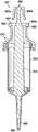
图6A-6B分别是与示例性发明性移液器一起使用的示例性0.1ml注射器的透视图和横截面侧视图;6A-6B are perspective and cross-sectional side views, respectively, of an exemplary 0.1 ml syringe for use with an exemplary inventive pipette;
图7A-7B分别是与示例性发明性移液器一起使用的示例性1.0ml注射器的透视图和横截面侧视图;7A-7B are perspective and cross-sectional side views, respectively, of an exemplary 1.0 ml syringe for use with an exemplary inventive pipette;
图8A-8B分别是与示例性发明性移液器一起使用的示例性10ml注射器的透视图和横截面侧视图;8A-8B are perspective and cross-sectional side views, respectively, of an exemplary 10 ml syringe for use with an exemplary inventive pipette;
图9A-9B分别是与示例性发明性移液器一起使用的示例性25ml注射器的透视图和横截面侧视图;9A-9B are perspective and cross-sectional side views, respectively, of an exemplary 25 ml syringe for use with an exemplary inventive pipette;
图10A-10B分别是与示例性发明性移液器一起使用的示例性50ml注射器的透视图和横截面侧视图;10A-10B are perspective and cross-sectional side views, respectively, of an exemplary 50 ml syringe for use with an exemplary inventive pipette;
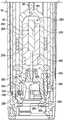
图11是图1A的示例性移液器的横截面侧视图,其中移除了移液器的外壳部分以更好地显示移液器的各种内部组件;11 is a cross-sectional side view of the exemplary pipette of FIG. 1A with a housing portion of the pipette removed to better show the various internal components of the pipette;
图12是图11的示例性移液器的各种内部驱动部件的放大横截面透视图;12 is an enlarged cross-sectional perspective view of various internal drive components of the exemplary pipette of FIG. 11;
图13是示例性电机驱动的外置活塞式移液器的远侧部分的放大剖视图,示出了形成示例性注射器保持机构的各种内部部件;13 is an enlarged cross-sectional view of a distal portion of an exemplary motor-driven external piston pipette showing various internal components forming an exemplary syringe retention mechanism;
图14A是示例性注射器活塞抓握机构的活塞托架元件的透视图,图14B-14C是该活塞载体元件的正视图;14A is a perspective view of a piston carrier member of an exemplary syringe piston gripping mechanism, and FIGS. 14B-14C are front views of the piston carrier member;
图15A是示出插入到图14A-14C的活塞载体元件中的示例性注射器的活塞头的分解图,其中还存在示例性注射器弹出机构的某些活塞释放元件;15A is an exploded view showing the plunger head of the exemplary syringe inserted into the plunger carrier element of FIGS. 14A-14C in which certain plunger release elements of the exemplary syringe ejection mechanism are also present;
图15B是图15A的稍微较少的分解图,其中还存在示例性注射器弹出机构的附加元件;Figure 15B is a slightly less exploded view of Figure 15A with additional elements of the exemplary syringe ejection mechanism also present;
图16表示如何将示例性注射器插入到示例性电机驱动的外置活塞式移液器中;Figure 16 shows how to insert an exemplary syringe into an exemplary motor-driven external piston pipette;
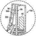
图17A是示出图16的注射器和移液器的放大视图,其中注射器部分地插入到移液器中,使得注射器的活塞头仅部分地由移液器的活塞头抓握机构接合;17A is an enlarged view showing the syringe and pipette of FIG. 16 with the syringe partially inserted into the pipette such that the plunger head of the syringe is only partially engaged by the plunger head gripping mechanism of the pipette;
图17B是示出图17A的注射器和移液器的放大视图,其中注射器进一步插入到移液器中,但尚未完全与其注射器保持机构接合;Figure 17B is an enlarged view showing the syringe and pipette of Figure 17A with the syringe further inserted into the pipette but not yet fully engaged with its syringe retention mechanism;
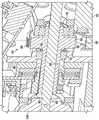
图18示出了图17的注射器和移液器,其中注射器完全插入到移液器中,使得注射器与移液器的注射器保持机构接合,并且注射器的活塞头与移液器的注射器活塞抓握机构接合;Figure 18 shows the syringe and pipette of Figure 17 with the syringe fully inserted into the pipette such that the syringe is engaged with the pipette's syringe retaining mechanism and the syringe's plunger head is gripped with the pipette's syringe plunger institutional engagement;
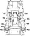
图19是图18的一部分的放大剖视图,示出了注射器保持机构和注射器活塞抓握机构的各种部件与注射器的元件的相互作用;19 is an enlarged cross-sectional view of a portion of FIG. 18 showing the interaction of various components of the syringe retention mechanism and syringe plunger gripping mechanism with elements of the syringe;
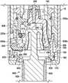
图20A-20D示出了示例性电机驱动的外置活塞式移液器的示例性注射器弹出机构的各种部件;20A-20D illustrate various components of an exemplary syringe ejection mechanism of an exemplary motor-driven external piston pipette;
图21A示出了图20A-20D的各种注射器弹出机构部件连同移液器的其他相关部件在注射器弹出操作开始之后不久的位置;Fig. 21A shows the various syringe ejection mechanism components of Figs. 20A-20D, together with other associated components of the pipette, in position shortly after the initiation of a syringe ejection operation;
图21B-21E进一步示出了图20A-20D的各种注射器弹出机构部件在注射器弹出操作进行时的位置;Figures 21B-21E further illustrate the positions of the various syringe ejection mechanism components of Figures 20A-20D during a syringe ejection operation;
图21F表示在示例性注射器弹出操作的最后阶段期间移液器的活塞载体部分的缩回运动;Figure 21F shows the retraction motion of the piston carrier portion of the pipette during the final stage of an exemplary syringe ejection operation;
图22是示例性电机驱动的外置活塞式移液器的一部分的放大横截面侧视图,示出了当移液器处于原始位置时其各种内部组件;22 is an enlarged cross-sectional side view of a portion of an exemplary motor-driven external piston pipette showing various internal components of the pipette when it is in a home position;
图23A-23B是根据本发明总体构思的具有附接的注射器的示例性电机驱动的外置活塞式移液器的横截面侧视图,并且图示了当移液器从原始位置移动到准备好完全抽吸的位置(例如可能由流体抽吸操作引起)时移液器和注射器活塞的各种内部部件的位置变化;23A-23B are cross-sectional side views of an exemplary motor-driven external piston pipette with an attached syringe in accordance with the present general inventive concept, and illustrate when the pipette is moved from a home position to ready Changes in the position of various internal components of pipettes and syringe plungers in the fully aspirated position (such as may be caused by fluid aspiration operations);
图24描绘了在一种示例性类型的流体分配操作期间示例性移液器和注射器组件的各种内部部件从图23B所示的完全抽吸位置的位置变化;以及Figure 24 depicts the positional change of various internal components of the exemplary pipette and syringe assembly from the fully aspirated position shown in Figure 23B during an exemplary type of fluid dispensing operation; and
图25是示例性电机驱动的外置活塞式移液器的底部透视图,其中颜色传感器连同各种其他组件一起可见。25 is a bottom perspective view of an exemplary motor-driven external piston pipette with the color sensor visible along with various other components.
具体实施方式Detailed ways
图1示出了根据本发明总体构思的手持式电机驱动的外置活塞式移液器5(为简洁起见,下文称为“移液器”)的一个示例性实施方式。图1中还示出了示例性一次性注射器600(参见图8A-8B)形式的消耗品,其安装到移液器以执行移液操作。与示例性创造性移液器一起使用的各种示例性注射器在图6A-10B中示出并在下面更详细地描述。图2示出了图1的移液器5和注射器600的组件。FIG. 1 shows an exemplary embodiment of a hand-held motor-driven external piston pipette 5 (hereinafter referred to as “pipette” for brevity) according to the present general inventive concept. Also shown in FIG. 1 is a consumable in the form of an exemplary disposable syringe 600 (see FIGS. 8A-8B ) that is mounted to the pipette to perform pipetting operations. Various exemplary syringes for use with exemplary inventive pipettes are shown in FIGS. 6A-10B and described in more detail below. FIG. 2 shows the assembly of the
图1-2的示例性移液器5包括用于由用户抓握的主体10。主体10通常是基本上中空的结构,其还用作移液器5的各种内部部件的外壳。在其他实施方式中,主体10可以具有不同的形状和/或尺寸,但是形状和尺寸通常在至少一定程度上由使用的人体工程学决定。The
主体10还包括近侧(用户)的近端10a和用作注射器600的连接端部的远端10b。在该示例中,主体10的近端10a包括用户界面部分15。还参考图3-4,可以观察到,该示例性移液器5的用户界面部分15进一步包括显示器20和各种致动器,诸如输入/选择按钮25a、25b、以及操纵杆27,如本领域技术人员将理解的,所述操纵杆27允许用户观察和选择移液器功能、观察和改变移液器设置以及参与与移液器的可编程控制器的各种其他交互。在移液器5的该示例性实施方式中,还提供触发开关30来用于启动移液器操作,且提供弹出按钮32来用于启动注射器弹出操作。The
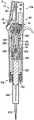
图5A是图2的示例性移液器5和注射器600组件的横截面侧视图,其揭示了移液器的被主体10隐藏的各种内部部件。如可以观察到的,除了其他部件之外,示例性移液器5包括电动驱动组件40、分配螺线管组件250、注射器保持机构150和注射器活塞抓握机构200,所有这些都在下面更详细地描述。图5A的组件还包括注射器600,其由移液器5的注射器保持机构150可释放地保持,并且被示出为处于抽吸后和分配前位置。图5B中示出了移液器主体10的近端10a的一部分的放大且透明的视图,并且展示了附加的移液器部件,诸如印刷电路板和各种电子部件,包括包含控制器90的电机控制电路。FIG. 5A is a cross-sectional side view of the
可与根据本发明总体构思的示例性移液器一起使用的各种示例性注射器在图6A-10B的透视图和横截面正视图中示出。示例性注射器500-600以体积增加的顺序布置,其中图6A-6B表示具有0.1ml体积的示例性注射器500,图7A-7B表示具有1.0ml体积的示例性注射器550,图8A-8B表示具有10ml体积的示例性注射器600,图9A-9B表示具有25ml体积的示例性注射器650,并且图10A-10B表示具有50ml体积的示例性注射器700。因此,虽然为了说明的目的,图8A-8B的示例性注射器600已经被任意选择为示例性移液器和注射器组件的注射器部件,但应当理解的是,示例性创造性移液器可与多个不同的注射器一起使用,以在宽体积范围内准确且可重复地分配样品。Various exemplary syringes that may be used with exemplary pipettes in accordance with the present general inventive concept are shown in perspective and cross-sectional elevation views of FIGS. 6A-10B . Exemplary syringes 500-600 are arranged in order of increasing volume, with FIGS. 6A-6B showing an
图6A-8B中所示的示例性注射器500、550、600中的每一个包括外部筒体,在本文中称为毛细管505、555、605,其具有大致中空和管状的构造并且用于容纳待分配的流体样本。每个毛细管505、550、605的远端包括具有孔口515、565、615的尖端510、560、610,先前抽吸到毛细管中的流体可以通过孔口515、565、615分配。每个毛细管505、555、605的顶部形成相同形状和尺寸的注射器保持元件520、570、620。注射器保持元件520、570、620的形状和尺寸允许其与位于移液器5中的注射器保持机构150接合。例如,在所示的特定注射器实施方式中,每个注射器保持元件520、570、620包括周向边缘535、585、635和可以由注射器保持机构150的元件接合的下表面540、590、640。Each of the
每个注射器500、550、600还包括活塞525、575、625(有时也称为柱塞),其具有同心地布置在毛细管505、555、605内用于抽吸和分配流体的第一流体接触部分、位于注射器保持元件520、570、620近侧的头530、580、630部分、以及穿过注射器保持元件中的缝隙以将活塞头与流体接触部分连接的连接部分。本文所示的示例性注射器500、550、600的活塞头530、580、630基本上为钟形,并且包括允许其至少一定程度的弹性变形的相对臂530a-530b、580a-580b、630a-630b。在其他实施方式中,其他活塞头形状和其他数量的臂也是可能的。Each
当注射器500、550、600适当地安装到移液器5时,注射器通过注射器的注射器保持元件520、570、620和移液器的注射器保持机构150的接合而保持在固定位置,并且活塞525、575、625的头530、580、630部分通过移液器的活塞抓握机构200接合,使得活塞的流体接触部分能够通过移液器在毛细管505、555、605内往复移动。注射器500、550、600在使用之后可从移液器5弹出,如下文更详细地描述。When the
分别在图9A-9B和图10A-10B中示出的示例性注射器650、700被设计成用于较大流体体积的移液中。在这些示例性注射器实施方式中,再次包括具有带孔口665、715的尖端660、710的毛细管655、705,并且活塞670、720再次布置成在毛细管内往复移动。然而,与图6A-8B所示的示例性注射器实施方式500、550、600不同,注射器650、700的毛细管655、705具有开口顶部(近端)并且不包括注射器保持元件。相反,每个注射器650、700包括用于将注射器连接到移液器5的可重复使用的适配器675、725。The
每个适配器675、725具有开口远端,该开口远端定尺寸成接收注射器650、700的近端。毛细管655、705的近端处和适配器675、725的远端处的保持元件协作以将毛细管固定到适配器。适配器675、725的近端形成注射器保持元件680、730,其形状和尺寸被设计成与移液器5中的注射器保持机构接合。例如,在所示的特定注射器实施方式中,每个注射器保持元件680、730包括周向边缘690、740和可以由注射器保持机构150的元件接合的下表面695、745。Each
每个注射器650、700包括:活塞620、720,其具有同心地布置在毛细管655、705内用于抽吸和分配流体的第一流体接触部分;头685、735部分,其位于适配器675、725的注射器保持元件680、730的近侧;以及连接部分,其穿过注射器保持元件中的缝隙以将活塞头与流体接触部分连接。本文所示的示例性注射器650、700的活塞头685、735也是大致钟形的,并且包括允许其至少一定程度的弹性变形的相对臂685a-685b、735a-735b。在其他实施方式中,其他活塞头形状和其他数量的臂也是可能的。Each
当大体积注射器650、700适当地安装到移液器5时,注射器通过适配器675、725的注射器保持元件680、730与移液器的注射器保持机构150的接合而保持在固定位置,且活塞头685、735通过移液器的活塞抓握机构200接合,使得活塞的流体接触部分能够通过移液器在毛细管655、705内往复移动。注射器650、700在使用之后可从移液器5弹出,如下文更详细地描述。When the
应当理解的是,图6A至图10B的注射器仅出于说明的目的而提供,当然也可以进行变更。例如但不限于,给定注射器的活塞头和活塞可以是单独的可接合元件,而不是如本文所述的单个元件的整体部分。It should be understood that the syringes of Figures 6A-10B are provided for illustrative purposes only and may of course be modified. For example and without limitation, the plunger head and plunger of a given syringe may be separate engageable elements rather than integral parts of a single element as described herein.
同样地,虽然仅将图9A-10B的示例性较大体积注射器650、700示出和描述为采用具有顶部开口的毛细管的适配器,但是同样可能的是,图6A-8B的较小体积注射器500、550、600可以具有类似的设计并且还包括适配器。当给定的注射器包括适配器时,适配器可以是可重复使用的部件而不是可消耗的部件,这在大多数注射器实施方式中将是注射器的其余部分。Likewise, while the exemplary
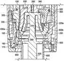
在图11中示出了图1的示例性移液器5的横截面侧视图,其中移除了其主体10以更好地揭示移液器的各种内部组件。如上面简要描述的,可以看到移液器5包括在近端的电动驱动组件40、在远端的注射器保持机构150、以及置于其间的分配螺线管组件250和注射器活塞抓握机构200。移液器5还包括内部壳体35,其容纳分配螺线管组件250、注射器活塞抓握机构200和注射器保持机构150中的每一个。电动驱动组件40附接到内部壳体35的近端。A cross-sectional side view of the
电动驱动组件40负责设置附接到移液器5的注射器600的各种位置,用于在远侧到近侧方向上移动注射器活塞以将流体抽吸到注射器中,用于在近侧到远侧方向上移动注射器活塞以从注射器分配流体,并且用于产生弹出注射器所需的运动。还参考图12,可观察到,在此示例性移液器5中,电动驱动组件40包含驱动电机45,其输出轴通过驱动带55连接到可旋转驱动螺母50,借此驱动电机对驱动螺母的旋转会引起导螺杆95的线性位移,导螺杆95穿过驱动螺母且与驱动螺母螺纹接合。在其他实施方式中可以使用其他驱动方案,例如直接驱动方案,其中驱动电机的输出通过连接器直接连接到导螺杆95,或者可能通过减速齿轮组件连接。The
在该示例性电动驱动组件40中,驱动带55可以将固定到电机45的输出轴的输出小齿轮60连接到输入小齿轮65,输入小齿轮65连接到驱动螺母50或与驱动螺母50成一体。驱动螺母50可具备轴承70以促进驱动螺母的旋转,且驱动螺母还可预加载有弹簧75(例如,波形弹簧),该弹簧75朝向移液器5的近端偏置驱动螺母以帮助解决电动驱动组件40内的任何制造(例如,堆叠)公差变化且将齿轮侧隙最小化,否则可能导致分配操作期间的不准确性。可以提供安装块80或类似的结构/部件以便安装电动驱动组件40的各种部件。In this exemplary
分配螺线管组件250构造成根据所选择的分配体积来独立地分配所选择的体积的流体,或者通过确保所有所选择的分配体积实际上从注射器600分配而无需使注射器尖端610接触样品接收容器来辅助电动驱动组件40具有分配功能(如下所述)。分配螺线管组件250包括螺线管体(线圈)255,螺线管体255位于活塞托架100内并且连接到活塞托架100,使得螺线管体随活塞托架轴向移动。螺线管主体255包括轴向孔270,轴向孔270从螺线管主体的轴向端部延伸到螺线管主体中一定距离。电枢260同心地位于孔270内,并且能够通过在孔内产生的磁场在孔内并相对于移液器5线性往复移动,如本领域技术人员将理解的。当电枢260在孔270内浮动而不是像螺线管主体255那样连接到活塞托架100时,电枢不受限制(在一定距离内)而随活塞托架线性移动。孔270的底壁在电枢260的近侧到远侧移动期间用作电枢硬止动件275。在所示的示例性分配螺线管组件250中,电枢260包括轴265,轴265朝向移液器5的远端延伸穿过孔270的底壁中的开口。Dispense
电动驱动组件40和分配螺线管组件250的操作由控制器90控制(参见图5B)。控制器90从诸如致动器25、30的用户输入和/或从内部编程接收指令信号。控制器90还从连接到驱动螺母50的编码器85接收位置信息信号。Operation of
驱动螺母50的旋转运动通过导螺杆95转换成线性(轴向)运动,导螺杆95穿过驱动螺母并与其螺纹接合。驱动螺母50可自由旋转,而导螺杆95旋转受限但可线性位移。因此,由驱动电机45引起的驱动螺母50的旋转将导致导螺杆95沿移液器5的纵轴在近端或远端方向上移动。The rotational motion of the
导螺杆95的远端95b以防止导螺杆95旋转的方式附接到活塞托架100的近端。活塞托架100位于托架保持器105中,托架保持器105安装在内部壳体35内以被限制相对于其移动。活塞托架100在托架保持器105内并且相对于移液器5的纵向轴线可轴向位移和往复移动,但旋转受到限制。The
分配螺线管组件250和注射器活塞抓握机构200(均在下文详细描述)基本上位于活塞托架100内。因此,在活塞托架在移液器5内线性位移期间,分配螺线管组件250和注射器活塞抓握机构200都与活塞托架100一起移动。Dispense
为了恰当的移液,注射器600必须牢固地保持在移液器5上,并且移液器5的电动驱动系统40必须连接到注射器活塞625以使注射器活塞在注射器毛细管605内往复移动。这些注射器保持和活塞连接功能分别由移液器5的示例性注射器保持机构150和注射器活塞抓握机构200执行。For proper pipetting, the
通过另外参考图13可以更好地理解移液器5的示例性注射器保持机构150,图13提供了示例性移液器5的远端的放大横截面视图。示例性注射器保持机构150被示出为包括多个间隔开的注射器闩锁元件155,这些注射器闩锁元件诸如通过销连接185固定在移液器5的远端内,以便可以在一些旋转运动范围内枢转,但限制轴向移动。在该示例性移液器5中,存在三个注射器闩锁元件155(在图11中仅两个可见),但是在其他实施方式中可以使用不同数量的闩锁元件。The exemplary
注射器保持机构150的注射器闩锁元件155在图11中示出为处于闭合位置,并且通过弹性O形环160或类似的弹性元件保持在常闭位置,弹性O形环160或类似的弹性元件环绕三个注射器闩锁元件155并且位于设置在每个闩锁元件中的狭槽165内。注射器闩锁元件155使用安装销185(参见图20D)连接到活塞载体205,这允许注射器闩锁机构在注射器插入过程期间枢转,这将在下文更全面地解释。The
注射器保持机构150的每个注射器闩锁元件155还包括在其远端处的闩锁钩170。注射器闩锁元件155的闩锁钩170设计成当注射器插入到移液器5的远端时接合注射器毛细管上的注射器保持元件。例如,关于图5中所示的移液器5和注射器600的布置,注射器闩锁元件155的闩锁钩170被设计成接合注射器毛细管605上的注射器保持元件620(例如,沿着下表面640)。Each
当注射器保持机构150将注射器600的毛细管固定到移液器5并将毛细管保持在相对于其的固定位置时,注射器活塞抓握机构200接合并可释放地保持注射器活塞625的头630。为此,注射器活塞抓握机构200包括基本上位于活塞托架100内的活塞载体205。如在图14A-14C中更详细地观察到的,至少活塞载体205的内部形状可以基本上与注射器活塞头630的外部形状一致。示例性活塞载体205还包括位于远侧的致动套环285,致动套环285具有活塞头保持唇缘210和多个径向间隔开的缝隙215,孔215允许通过示例性注射器弹出机构的活塞头释放元件305穿过活塞载体的壁进入活塞头630的臂630a、630b,如下文进一步描述。The syringe
多个间隔开的活塞头释放元件引导件220从活塞载体205的致动套环285横向向外延伸。如可以观察到的(也参见图17A-17B和图21A-21E),每个活塞头释放元件引导件220的朝内的面220a具有倾斜(凸轮)形状,其在注射器弹出操作期间引导相应一个活塞头释放元件305的远侧部分的移动。每个活塞头释放元件引导件220的朝外的表面220b可以促进活塞载体205在内部壳体35内的轴向移动和/或可以起到限制活塞载体旋转的作用。A plurality of spaced apart piston head release element guides 220 extend laterally outward from the
活塞载体205的近端205a构造成便于将活塞载体连接到分配螺线管组件250的电枢轴265的远端。因此,在组装好的移液器5中,活塞载体205能够通过电动驱动组件40与活塞托架100一起往复移动,并且还能够通过分配螺线管组件250在活塞托架内独立地往复移动。The
通过参考图15A-15B的分解视图可以更好地理解活塞载体205的操作。图15A示出了示例性注射器600,其活塞头630插入到图13和图14A-14C的活塞载体205中,其中示例性注射器弹出机构的活塞头释放元件305可枢转地位于活塞载体中的缝隙215中。活塞头630优选地紧密地装配在活塞载体的内部内,并且可以观察到,活塞头臂630a、630b的远端与活塞载体205中的活塞头保持唇缘210接合,从而防止活塞头630从活塞载体取下。因此,活塞头630被活塞载体205牢固地抓住,并且确保注射器600的活塞625将随着活塞载体的任何轴向移动而轴向移动。The operation of the
现在参考图16-17B,可以观察将示例性注射器600插入到示例性移液器5的过程。图16示出了位于移液器5的远端下方并且与其基本上轴向对准的注射器600。箭头表示注射器600朝向移液器5的接合移动的方向。Referring now to FIGS. 16-17B , the process of inserting the
在图17A中,注射器600已经部分地插入到移液器5中。在注射器600的插入期间,注射器活塞625的活塞头630开始与注射器活塞抓握机构200的活塞载体205接合。在图17A中可以观察到,在注射器插入过程期间,活塞头630的活塞头臂630a、630b经由与由活塞载体205的致动套环285中的远侧开口290形成的壁接触而向内压缩(即,经历向内定向的弹性变形)。活塞头臂630a、630b的向内压缩允许注射器活塞头630穿过致动套环285中的远侧开口。In FIG. 17A , the
图17B描绘了由于注射器600的近端继续插入到移液器5的远端中超过图17A所示的点而导致的注射器600和移液器5的部分接合。注射器600的这种持续插入导致注射器闩锁元件155的远端在施加到注射器600的插入力下向外枢转移动。更具体地,当注射器600插入到移液器5中时,注射器保持元件620在注射器闩锁元件155的远端上施加所产生的向外朝向的力,该力足以克服由O形环160在注射器闩锁元件上施加的朝内的力。Figure 17B depicts the partial engagement of the
随着注射器600继续插入移液器5,注射器毛细管605的注射器保持元件620的近侧(上)面与保持在移液器5内的一个或多个弹簧300邻接接触。如可以在图17B中观察到的那样,在注射器保持元件620的近侧(上)面和弹簧300之间的接触点处,注射器保持元件620优选地已经移动经过注射器闩锁元件155的闩锁钩170(尽管或许可能需要弹簧的轻微压缩才能到达所述点),这允许注射器闩锁元件155通过O形环160的收缩力返回到它们的常闭位置。在注射器闩锁元件155返回到其常闭位置时(也参见图18-19),每个注射器闩锁钩170上的平坦部175覆盖并接合注射器保持元件620的下表面640,同时每个注射器闩锁元件155的面向内的表面180优选地通过O形环160的收缩弹簧力压靠注射器保持元件的周向边缘635。注射器毛细管605由此被截留抵靠移液器5并可释放地锁定到移液器5,这意味着注射器毛细管也相对于移液器牢固地保持在固定位置。As the
在将注射器600可释放地锁定到移液器5之后,如图17B所示并且如上所述,在注射器上继续施加插入力导致注射器轻微但额外向近侧移动到移液器中。注射器600的这种额外移动是由于施加在注射器上的插入力压缩移液器中的弹簧300而产生的。After the
如图18中所示,注射器600进入移液器5中的额外近侧移动允许注射器的活塞头630变得完全插入到活塞载体中,此后活塞头臂630a、630b将弹性返回到其正常静态位置并与位于活塞载体的致动套环285中的活塞头保持唇缘210接合,如图18中所示。活塞头臂630、630b与致动套环285的接合将活塞头630保持在活塞载体205中。在图18中还可观察到,在移液器205的此示例性实施方式中,活塞头630紧贴地装配在活塞载体205的内部。As shown in Figure 18, the additional proximal movement of the
在图18-19中,注射器600完全安装到移液器5。在完全安装位置,注射器600如上所述可释放地锁定到移液器5,并且注射器的活塞头由移液器的注射器活塞抓握机构200完全接合。一旦放置在所示的完全安装位置,注射器600可用于抽吸和分配流体。In FIGS. 18-19 , the
除了在注射器毛细管605的注射器保持元件620已经到达与移液器的注射器保持机构150的接合位置之后提供注射器600到移液器5中的额外插入之外,弹簧300还提供注射器600到移液器5的增加的保持安全性和固定接合。更具体地,在注射器600安装到移液器5的情况下,弹簧300抵靠注射器保持元件620的上表面并施加朝向远侧的力,这将注射器保持元件的下表面640紧紧地压靠在注射器闩锁元件155的钩170的平坦部175上。由弹簧300施加的朝向远侧的力还将活塞头630推向移液器5的远端,这将活塞头臂630a、630b的远端紧紧地压靠在活塞载体205的致动套环285部分中的活塞头保持唇缘210上。因此,注射器保持元件620相对于注射器保持机构150的注射器闩锁元件155的任何可能的意外移动和/或活塞头630相对于活塞载体205的移动都会受到弹簧300所施加的轴向力的阻止,从而进一步将注射器600固定到移液器5。弹簧300可以是例如但不限于金属片弹簧。也可以使用其他类型的弹簧。In addition to providing additional insertion of the
因为外置活塞式移液器注射器是一次性的,即,旨在在完成相关移液操作之后丢弃,所以示例性注射器600必须能够从移液器5弹出。如从图20A-20D的分解透视图和图21A-21F的横截面图(也参见图13、图15A-15B和图17A-19)的回顾可最佳理解,移液器5具备用于此目的的示例性注射器顶出机构。一般而言,注射器弹出机构可操作以将注射器600的注射器保持元件620从注射器保持机构150分离,并且将注射器活塞头630从活塞载体205分离,此后注射器将自动地从移液器5弹出。如下面更详细解释的,示例性移液器5的注射器弹出机构通常包括电动驱动组件40和导螺杆95、活塞托架100及其楔形注射器闩锁元件释放部分335、注射器闩锁元件155、活塞载体205的致动套环部分285上的活塞头释放元件引导件220、以及多个活塞头释放元件305。Because the external piston pipette syringe is disposable, ie, intended to be discarded after the associated pipetting operation is completed, the
图20A基本上提供了插入到图15A中所示的活塞载体205中的示例性注射器600的活塞头630的相同视图,除了在图20A中为了进一步清楚起见已移除活塞载体205。在图20A中可以观察到,注射器弹出机构的活塞头释放元件305(其在图15A中示出为与活塞载体205中的缝隙215对准)布置成当活塞头插入到活塞载体205中时至少部分地覆盖注射器活塞头630的相对臂630a、630b。每个示例性活塞头释放元件305可在其远端包括辊310。辊310用于减小活塞头释放元件305与活塞载体205的每个活塞头释放元件引导件220的朝内的倾斜面220a之间以及活塞头释放元件与注射器活塞头630的臂630a、630b之间的摩擦。然而,在其它注射器弹出机构实施方式中,例如通过使用低摩擦材料等,可以消除辊310。Figure 20A provides substantially the same view of the
活塞头释放元件305通过销315可枢转地固定在活塞托架100内,使得活塞头释放元件的近端的向内移动将导致活塞头释放元件的远端的向外移动。虽然为了清楚起见未在图20A-20D中示出,但是活塞头释放元件305通过O形环320或另一个类似弹性元件保持在常开位置(参见例如图13、16-19、21A-21B、22和24),O形环320或另一个类似弹性元件环绕活塞头释放元件305并位于设置在每个活塞头释放元件中的槽325内。O形环320对每个活塞头释放元件305的近端施加向内方向的力,使得活塞头释放元件的常开位置是活塞头释放元件的远端从活塞载体205推离的位置。Piston
图21A-21F中示出了示例性注射器弹出操作。在注射器弹出操作期间,活塞载体205抵靠硬止动件225来放置,并且命令电动驱动组件40以引起活塞托架100向远侧移动某一预定距离。在移液器5的此示例性实施方式中,活塞托架在注射器弹出操作期间在远端方向上移动约3.25mm,但该距离在其他实施方式中可能会不同。An exemplary syringe ejection operation is shown in Figures 21A-21F. During a syringe ejection operation, the
因为活塞载体205在抵靠硬止动件225时被约束以防止进一步的朝向远侧的轴向移动,所以活塞托架100的上述朝向远侧的轴向位移将导致其闩锁元件释放部分335相对于活塞载体以及可枢转地连接到活塞托架100的活塞头释放元件305的朝向远侧的轴向位移。Because the
参考图21A,可以观察到,当活塞托架100向远侧移动时,活塞托架的注射器闩锁元件释放部分335开始接触注射器闩锁元件的近端,该注射器闩锁元件释放部分335布置成与注射器闩锁元件155对准并且定位成在注射器闩锁元件与活塞载体205之间的空间中移动。同样,活塞托架100的远侧移动产生活塞头释放元件305的辊310和与活塞载体205的致动套环285相关的每个活塞头释放元件引导件220的向内定向的倾斜面220a之间的接触。Referring to Figure 21A, it can be observed that as the
图21B示出了活塞托架100的持续远侧移动最终导致其楔形注射器闩锁元件释放部分335与注射器闩锁元件155的近端之间的充分接触,以引起注射器闩锁元件的远端围绕安装销185向外枢转并抵抗O形环160的抵消收缩力和弹簧300的轴向力。如上所示,注射器闩锁元件155的这种枢转移动导致其闩锁钩170从注射器600的注射器保持元件620脱离(也如图20D所示),从而将注射器保持元件和注射器毛细管605从与移液器5的保持接合中释放。Figure 21B shows that continued distal movement of the
现在参考图21C-21E,可以进一步观察到,活塞托架100的额外远侧移动使得活塞头释放元件305的辊310跟随活塞载体致动套环285的相应对准的活塞头释放元件引导件220的倾斜面220a。因此,活塞头释放元件305的远端朝向活塞载体205向内枢转。如图21D-21E所示,活塞头释放元件305的远端的这种向内移动导致附接到其上的辊310通过其中的缝隙215进入活塞载体205,并且接触注射器活塞头630的相对臂630a、630b并开始向内压缩(变形)该相对臂。Referring now to FIGS. 21C-21E , it can be further observed that the additional distal movement of the
如图21E所示,由活塞头释放元件305产生的注射器活塞头臂630a、630b的向内变形量最终足以使臂从活塞载体205的致动套环285中的活塞头保持唇缘210脱离。注射器活塞头臂630a、630b的这种脱离将活塞头630从活塞载体205释放,并且允许注射器活塞头630此后通过活塞载体中的远侧开口290沿近侧至远侧方向返回。21E, the amount of inward deformation of the syringe
当活塞头臂630a、630b在活塞托架100的向下移动期间被活塞头释放元件305的远端向内压缩时,每个活塞头释放元件的位于近侧的弹出片340同时在活塞头630的顶部上施加朝向远侧的(弹出力)。该朝向远侧的力导致活塞头630和毛细管605的类似位移,并且还导致活塞头臂630a、630b的自由端进入活塞载体205中的远侧开口290。When the
在注射器元件如上所述定位的情况下,整个注射器600可以从移液器5弹出。在该示例性实施方式中,注射器600的实际弹出通过首先将活塞托架100(参见图21F)缩回到其原始位置而发生,该缩回移动允许活塞头臂630a、630b在弹出期间清除活塞头释放元件305的辊310。此后,物理弹出可由于重力结合由弹簧300施加在注射器保持元件620上的轴向力而自动发生,和/或注射器600可以由用户从移液器5移除。活塞托架100的弹出移动以及返回移动可根据来自移液器控制器90的弹出操作程序命令自动发生。With the syringe elements positioned as described above, the
现在将参照图22-24描述示例性移液器5的各种状态和操作。图22表示示例性移液器5的原始位置。在原始位置,活塞载体205的远端基本上保持抵靠硬止动件225,应当理解的是,保持抵靠硬止动件允许在硬止动件和活塞载体之间存在最小的组装间隙。同样地,在移液器5的原始位置,分配螺线管组件250的电枢260在其远侧硬止动件处抵靠芯270的底壁,并且分配螺线管组件的线圈260不通电。在移液器5的原始位置中,活塞托架100在远端定位成使得在活塞载体205与活塞头释放元件305的辊310之间存在微小间隙400,使得在将注射器插入到移液器5中时在辊与活塞头630之间不存在意外干涉。可以提供原始位置传感器405以向控制器90表明活塞托架处于原始位置。Various states and operations of the
在图23A-23B中通过使用图2的示例性移液器5和注射器600组件来表示示例性移液器的抽吸功能。图23A示出了处于原始位置的示例性移液器5,上面刚刚说明。可进一步观察到,当移液器5处于原始位置且注射器600安装到其上时,注射器活塞625的活塞头630与移液器的活塞载体205接合,但活塞尚未有意地朝向移液器的近端移动(除了使活塞头与活塞载体接合所必需的任何偶然轴向移动之外)。因此,活塞625仍然基本上抵靠注射器毛细管605的远侧内部。The aspiration function of the exemplary pipette is represented in FIGS. 23A-23B using the
图23B的移液器组件描绘为处于准备分配或完全抽吸位置,即,移液器5展示为已执行抽吸功能,通过所述抽吸功能,所关注流体的全注射器体积被抽吸到注射器600中。还可以抽吸小于全注射器体积的流体。为了抽吸流体,将注射器600的尖端610放置在流体中,且经由移液器的用户界面部分15或用户操纵致动器来启动抽吸程序以将电动驱动组件40的电机45通电,从而朝向移液器5的近端驱动活塞托架100和连接到其的相关联组件某一所要距离。活塞托架100的这种朝向近侧的轴向移动产生螺线管主体260的类似移动,这又产生电枢260和附接到电枢轴265的活塞载体205的类似移动。由于注射器活塞625的头630与活塞载体205接合,所以注射器活塞也在注射器毛细管610内向近侧移动相等的距离,这将所关注的流体抽吸到现在排空的毛细管中。The pipette assembly of Figure 23B is depicted in a ready-to-dispens or full aspirate position, i.e.,
当示例性移液器5处于完全抽吸位置时,例如图23B中所示,移液器组件中的各种组件仍将相对于其他组件驻留在与移液器驻留在原始位置时相同的位置。例如,分配螺线管组件250的电枢260抵靠孔270的底壁保持在其远侧硬止动件275处,并且分配螺线管组件的线圈260不通电。同样,当移液器5处于抽吸位置时,活塞载体205与活塞头释放元件305的辊310之间的间隙400也得以维持。When the
参考图23B和图24描述在分配操作期间各种移液器部件的动作。在分配操作期间启动移液器5的分配部件的具体方式取决于所选择的分配体积。也就是说,优选地使用螺线管组件250执行小体积分配,而优选地单独使用电动驱动组件40或使用电动驱动组件40结合螺线管组件250执行大体积分配。The action of various pipette components during a dispensing operation is described with reference to FIGS. 23B and 24 . The specific way in which the dispensing components of the
在不同的移液器实施方式中,小分配体积和大分配体积之间的界限可能会有所不同,因为可以由螺线管组件250单独分配的流体的最大体积取决于螺线管电枢260的最大冲程,该最大冲程又由活塞托架100在导致流体从注射器600意外分配之前从完全抽吸位置朝向移液器5的远端移动的最大距离来确定。出于说明而非限制的目的,在移液器5的该示例性实施方式中,可以在不引起意外分配的情况下产生的最大活塞托架位移为0.5mm。The boundaries between the small and large dispensing volumes may vary in different pipette implementations, as the maximum volume of fluid that can be dispensed by the
因为螺线管主体255连接到活塞托架100,所以螺线管主体在活塞托架的类似移动期间朝向移液器5的远端移动。然而,由于螺线管的电枢260在螺线管主体255中的孔内自由浮动,由于螺线管电枢也通过电枢轴265连接到活塞载体205,并且由于活塞载体通过注射器600中的抽吸流体推动注射器活塞670的压力朝向移液器5的近端偏置,螺线管电枢保持在其当前位置并且在活塞托架的前述移动期间不与活塞托架和螺线管主体一起移动。这在电枢260的远侧面260b与螺线管主体255中的孔270的底壁之间产生螺线管冲程间隙280,该螺线管冲程间隙280的距离与活塞托架100的前述远侧移动相当(在该示例中高达0.5mm)。该螺线管冲程间隙280是螺线管电枢260的最大冲程,因此在移液器5的该示例性实施方式中也是0.5mm。Because the
螺线管电枢260的0.5mm最大冲程导致安装到移液器的给定注射器的总体积的约0.01(1%)的相应分配体积。因此,对于该特定示例,小分配体积将被认为是0.1ml体积注射器500的约0.001ml或更小、1.0ml体积注射器550的约0.01ml或更小、10ml体积注射器600的约0.1ml或更小、25ml体积注射器650的约0.25ml或更小、以及50ml体积注射器700的约0.5ml或更小。在该特定示例中,大于这些近似小体积分配体积的分配体积将被认为是大体积分配体积。请注意,单独使用电动驱动组件40或电动驱动组件40与螺线管组件250组合的最小可输送分配体积通常与单独使用螺线管组件的最大可输送分配体积相同(尽管可能存在一些重叠)。The 0.5mm maximum stroke of the
在开始小体积分配操作时,移液器5的控制器90指示电动驱动组件40将活塞托架100朝向移液器的远端移动一定距离(小于或等于0.5mm,取决于待分配的选定小体积)。活塞托架100移动的具体距离取决于待分配的流体的选定小体积。在该示例性移液器5中,最大活塞托架100位移距离和所产生的螺线管电枢260冲程为0.5mm。At the start of a small volume dispensing operation, the
在活塞托架100移动到小体积分配位置且因此产生螺线管组件中的间隙280的情况下,控制器90暂时为螺线管主体255通电,如本领域技术人员将理解的,螺线管主体255产生磁场,所述磁场朝向移液器5的远端快速且有力地触发电枢260且停止与电枢硬止动件275接触。螺线管组件电枢260的这种快速且向远侧定向的移动产生活塞载体205和与其连接的注射器活塞625的类似移动,这使得选定分配体积的流体以足够的速度从注射器600的尖端610喷出,以破坏流体和注射器毛细管610的内壁表面之间的任何表面张力,从而确保最后一滴流体被分配,而无需接触接收容器上的注射器尖端610。可以重复移动活塞托架100和通过触发螺线管组件250分配小流体体积的过程,直到完全分配抽吸体积或直到已经完成所需数量的分配操作。With the
从前面的描述可以理解,在示例性移液器的上下文中的大体积分配仅仅是分配大于能够通过螺线管组件单独的动作分配的最大可能流体体积的流体体积。因此,关于本文所示和所述的示例性移液器5和示例性注射器500、550、600、650、700,大体积分配涵盖大于0.1ml体积注射器500的约0.001ml、1.0ml体积注射器550的0.01ml、大于10ml体积注射器600的约0.1ml、大于25ml体积注射器650的约0.25ml、大于50ml体积注射器700的约0.5ml。在单次大体积分配操作期间可以分配的最大体积是给定注射器500、550、600、650、700的整个体积。As can be appreciated from the foregoing description, a large volume dispensing in the context of an exemplary pipette is simply dispensing a volume of fluid that is greater than the maximum possible volume of fluid that can be dispensed by a single action of the solenoid assembly. Thus, with respect to the
如上所述,大体积分配的两种方法是可能的。根据第一种方法,仅使用电动驱动组件40执行大体积分配,而根据第二种方法,使用电动驱动组件40结合螺线管组件250执行大体积分配。所采用的大体积分配方法可取决于移液器的具体构造,并且还可能取决于要分配的流体的特性。As mentioned above, two methods of large volume dispensing are possible. According to the first method, only the
根据上述大体积分配方法的第一种方法,已经发现,在分配大流体体积时,或者至少在分配落入示例性移液器5的整个大体积分配范围的某个体积范围内的流体体积时,可以在无需来自螺线管组件250的辅助的情况下执行分配。更具体地,已经发现,在分配大的流体体积时,活塞托架100单独移动,加上由于注射器600中的流体被迫从较大直径的毛细管605通过直径小得多的尖端610和孔口615而导致的流体速度的增加,可以足以产生足够大的流体分配速度,以克服流体和注射器毛细管的内壁表面之间的任何表面张力,从而确保最后一滴流体从注射器分配,而无需接触接收容器上的注射器尖端。In accordance with the first of the aforementioned large volume dispensing methods, it has been found that when dispensing large fluid volumes, or at least when dispensing fluid volumes that fall within a certain volume range of the entire large volume dispensing range of the
移液器控制器90可以根据用户选择的分配程序、安装到移液器5的注射器、与所选择的分配程序相关联的分配体积等,仅通过活塞托架100的移动来自动引导大体积分配。在任何情况下,在仅通过活塞托架100的移动开始大体积分配操作时,控制器90确定喷射待分配的选定大体积流体所需的活塞托架的位移。电动驱动组件40随后旋转驱动螺母50以使丝杠95和活塞托架100线性位移,直到活塞载体205和活塞头释放元件305的辊310之间的间隙400闭合,这产生活塞载体205和与其接合的注射器活塞625的类似位移。因此实现了选定的大流体体积的分配。The
替代地,大体积分配可以通过活塞托架移动和螺线管组件250的触发的组合来实现。与第一种大体积分配方法一样,第二种大体积分配方法可以由移液器控制器90基于用户选择的分配程序、安装到移液器5的注射器、与所选分配程序相关联的分配体积等来自动选择。在任何情况下,在开始第二种大体积分配操作时,控制器90再次确定喷射待分配的选定大体积流体所需的活塞托架的位移。电动驱动组件40随后旋转驱动螺母50以使导螺杆95和活塞托架100线性位移所需距离,这产生活塞载体205和与其接合的注射器活塞625的类似位移、以及从注射器相应地分配流体。Alternatively, bulk dispensing may be achieved by a combination of piston carrier movement and activation of
在完成活塞托架100的运动和来自注射器600的流体的相应分配时,控制器90暂时对螺线管主体255通电,这会向移液器5的远端触发螺线管组件250的电枢260并停止与电枢硬止动件275的接触。螺线管组件电枢260的这种快速且向远侧定向的移动产生活塞载体205和注射器活塞625的类似移动,这将分配由于流体和注射器毛细管610的内壁表面之间的表面张力而残留在注射器尖端610中的任何未分配的流体。因此,可以确保旨在分配的流体体积的最后一滴实际上被分配并且不会无意地保持在注射器尖端610中。当在大体积流体分配操作期间分配的流体的体积小于注射器600中的流体的总体积时,可以重复分配操作,直到已经完成所需数量的分配操作,直到流体体积耗尽,或者直到剩余流体体积不足以执行所需流体体积的另一个分配操作。Upon completion of movement of the
使用示例性移液器5的分配操作可经由以自动型(自动)模式或经由手动模式操作移液器的所选移液程序来完成。如上所述,用户能够经由移液器5的用户界面部分15访问并选择性地启动所需的吸量程序。Dispensing operations using the
自动模式分配可以包括多个不同的和可选择的分配过程。这种分配过程的一个简单示例导致流体的全部注射器体积的抽吸,随后在一个分配操作中分配全部抽吸的流体体积。Automatic mode dispensing can include a number of different and alternative dispensing processes. A simple example of such a dispensing process results in the aspiration of the entire syringe volume of fluid, followed by dispensing the entire aspirated fluid volume in one dispensing operation.
在另一个自动模式分配程序示例中,将一定体积的流体抽吸到注射器600中,如前所述,且随后以相等体积的多个剂量分配,直到已完成所需数量的分配操作,直到流体体积耗尽为止,或直到剩余流体体积不足以执行选定流体体积的另一个分配操作为止。在又一自动模式分配程序示例中,将一定体积的流体抽吸到注射器600中,如前所述,且随后以可变体积的多个剂量分配,直到已完成所需数量的分配操作,直到流体体积耗尽为止,或直到剩余流体体积不足以执行所要的流体体积的另一个分配操作为止。在又一自动模式分配过程示例中,如前所述,一定体积的流体被抽吸到注射器600中,并且随后以相等或可变体积的多个剂量分配,直到已经分配了抽吸体积的一些部分(例如,50%)。此时,执行另一个抽吸操作以增加注射器600中的流体体积,并且再次执行分配。可以重复该过程,直到已经完成所需数量的分配操作,直到流体体积耗尽,或者直到剩余流体体积不足以执行选定流体体积的另一个分配操作。In another example of an automatic mode dispensing procedure, a volume of fluid is drawn into the
在任何上述示例性自动模式分配程序中,抽吸的流体体积可以是安装的注射器的整个流体体积,或一些较小的体积。流体的分配可以通过单独触发螺线管组件250、通过单独移动活塞托架100或通过其组合来实现。如上所述,可以基于移液器构造(例如,分辨率)、安装的注射器、所需的分配体积、它们的一些组合和/或其他因素来选择所使用的分配方法。In any of the above-described exemplary automatic mode dispensing procedures, the fluid volume drawn may be the entire fluid volume of the installed syringe, or some smaller volume. Dispensing of fluid can be accomplished by actuating
可以在示例性移液器的自动模式下执行的示例性过程的菜单还可包括滴定过程。如本领域技术人员将理解的,使用示例性移液器5的滴定程序通常涉及将一定量的已经被抽吸到注射器600中的滴定剂添加到分析物和指示剂的容器中,直到指示剂改变颜色或实现一些其他可观察的特性,表明反应已经达到中和状态。由于需要添加到分析物溶液中以达到中和的滴定剂的量通常是未知的,因此滴定程序可以包括表示已经分配的滴定剂的体积的滴定体积计数器。计数器可以是可重置的,以允许来自单次吸入体积的滴定剂的多次滴定操作。The menu of example procedures that may be performed in the automatic mode of the example pipette may also include a titration procedure. As will be understood by those skilled in the art, a titration procedure using the
分配操作也可以由用户在手动模式下执行,而不是由移液器5的控制器90在自动模式下操作。在手动模式中,用户操作电动驱动组件40以从注射器600产生快速或缓慢抽吸和/或分配流体。The dispensing operation can also be performed by the user in manual mode, rather than by the
示例性移液器也可以具有流体粘度检测能力。更具体地,可以间接地确定所关注的流体的粘度,诸如通过向移液器提供适当的电路350(参见图5B)或用于监测和分析由驱动电机引起的增加的电流消耗的其他装置,该增加的电流消耗是由于在抽吸或分配操作期间相对于注射器毛细管移动注射器活塞所需的增加的电机扭矩;通过使用所提供的负荷传感器355(参见图5B),其测量在抽吸或分配操作期间相对于注射器毛细管移动注射器活塞所需的力;通过机械弹簧;或者经由本领域技术人员将理解的另一种技术。Exemplary pipettes may also have fluid viscosity detection capabilities. More specifically, the viscosity of the fluid of interest can be determined indirectly, such as by providing appropriate circuitry 350 (see Figure 5B) to the pipette or other means for monitoring and analyzing the increased current draw caused by the drive motor, This increased current draw is due to the increased motor torque required to move the syringe plunger relative to the syringe capillary during an aspiration or dispense operation; by using the provided load cell 355 (see Figure 5B), which measures the The force required to move the syringe plunger relative to the syringe capillary during operation; by a mechanical spring; or via another technique that will be understood by those skilled in the art.
当利用电流消耗监测技术时,电流消耗的值可用于对流体的粘度进行分类,并且移液器控制器可基于所识别的流体粘度类别来调整移液器的分配操作参数。例如但不限于,如果确定所关注的流体具有低粘度,则控制器可以在流体分配操作期间应用正常分配设置。如果确定所关注的流体具有中等粘度,则控制器可以增加驱动电机的电压,并且还可以实施回吸模式(将空气吸入注射器毛细管的导螺杆的缩回),在分配低粘度的流体期间通常无需回吸的等分试样。如果所关注的流体被确定为具有高粘度,则控制器可以禁用螺线管组件,因此仅经由活塞托架的移动可以进行分配,并且还可以通知用户将需要注射器尖端接触以确保没有液体留在注射器尖端中。When utilizing current draw monitoring techniques, the value of current draw can be used to classify the viscosity of the fluid, and the pipette controller can adjust the pipette's dispensing operating parameters based on the identified fluid viscosity class. For example and without limitation, if the fluid of interest is determined to have low viscosity, the controller may apply normal dispensing settings during a fluid dispensing operation. If it is determined that the fluid of interest is of moderate viscosity, the controller can increase the voltage to the drive motor, and can also implement a suck back mode (retraction of the lead screw that draws air into the syringe capillary), typically not required during dispensing of low viscosity fluids Aspirate the aliquot back. If the fluid of interest is determined to be of high viscosity, the controller can disable the solenoid assembly so that only movement of the piston carrier can be dispensed, and can also notify the user that syringe tip contact will be required to ensure no liquid is left behind in the tip of the syringe.
诸如示例性移液器5之类的示例性移液器也可被编程为执行丢弃分配功能。丢弃分配功能优选地是使用示例性移液器5时的移液过程的一部分,并且可由控制器90实施。一般而言,丢弃分配功能可操作以去除任何侧隙并解决驱动器、螺线管和整个系统中的任何制造和/或组装公差问题,并且还可以去除夹带在注射器尖端的远端附近的任何空气。控制器90可以被编程为在每次抽吸操作之后启动丢弃分配功能。废弃分配功能还可以在先前抽吸到注射器中的所有流体完全分配的任何时间启动。丢弃的分配体积将基于所使用的液体的粘度和注射器结构而变化。Exemplary pipettes, such as
可以根据本发明总体构思提供的另一个可能的示例性移液器特征是自动注射器识别功能。因为示例性移液器可与许多不同体积的注射器一起使用,所以应认识到,如果示例性移液器可在将注射器安装到移液器时自动地识别注射器体积将是有益的。这种能力将允许移液器的控制器针对给定的注射器容积自动选择适当的操作参数,从而简化设置过程并且可能消除与错误地识别所使用的注射器的容积相关联的操作员错误。Another possible exemplary pipette feature that may be provided in accordance with the present general inventive concept is an auto-injector identification function. Because the example pipette can be used with many syringes of different volumes, it will be appreciated that it would be beneficial if the example pipette could automatically identify the syringe volume when the syringe is mounted to the pipette. This capability would allow the pipette's controller to automatically select the appropriate operating parameters for a given syringe volume, simplifying the setup process and potentially eliminating operator error associated with erroneously identifying the volume of the syringe used.
在一个示例性实施方式中,颜色编码用作注射器识别的机制。更具体地,每个注射器体积与不同的颜色相关联,并且相应颜色的区域位于注射器上。In one exemplary embodiment, color coding is used as a mechanism for syringe identification. More specifically, each syringe volume is associated with a different color, and areas of the corresponding color are located on the syringe.
使用图6A-10B中描绘的示例性注射器500、550、600、650、700作为示例,对应于每个给定注射器的体积的色带450、455、460、465、470沿着注射器保持元件520、570、620、680、730的上肩部520a、570a、620a、680a、730a放置。在一些实施方式中,给定注射器的色带可以仅部分地围绕注射器保持元件延伸,而在其他实施方式中,色带可以围绕注射器保持元件的整个圆周延伸。还可以以颜色的连续块、颜色的离散块的形式或任何其他可读形式(诸如但不限于点、分段线等的集合)提供颜色编码。颜色也可以模制到制成给定注射器保持元件的材料中。此外,在替代实施方式中,可以将颜色编码放置在注射器活塞上,而不是放置在给定注射器的注射器保持元件上或除此之外。Using the
如图24所示,一个或多个颜色传感器475可以位于示例性移液器5的远端内,并且可以被构造和定位成将色带成像在示例性注射器500、550、600、650、700的注射器保持元件520、570、620、680、730上。在将示例性注射器500、550、600、650、700安装到移液器5时,颜色传感器475对色带450、455、460、465、470进行成像,并向移液器控制器90发送表示色带颜色的信号。控制器90被提供适当的数据(例如,查找表等)—例如通过使用颜色传感器475的初步和离线颜色识别和配准操作的过程—分析从颜色传感器475接收的信号以识别色带450、455、460、465、470的颜色,并因此识别安装的注射器500、550、600、650、700的体积。如上所述,在识别注射器体积的情况下,控制器90可以继续自动设置各种移液参数中的任何参数和/或向移液器5的用户表明注射器体积。As shown in FIG. 24, one or
在本文提出的示例性移液器和注射器实施方式中,注射器保持元件520、570、620、680、730的上肩部520a、570a、620a、680a、730a优选地以一定角度(例如,相对于保持元件的上表面在30°和60°之间)倒角。注射器保持元件520、570、620、680、730的倒角上肩部520a、570a、620a、680a、730a便于将注射器保持元件插入到移液器5中。另外,每个注射器保持元件的倒角上肩部520a、570a、620a、680a、730a提供有角度的表面,由颜色传感器475的发射器部分(照明源)480发出的光可以从该有角度的表面朝向颜色传感器475的检测面485反射,该检测面485可以以对应的角度安装到移液器。使用这种倒角肩部还允许使用垂直移印工艺来施加色带,这是最有效的印刷方式。In the exemplary pipette and syringe embodiments presented herein, the
虽然本文出于说明的目的示出和描述了使用颜色传感器475来读取注射器保持元件520、570、620、680、730的倒角上肩部520a、570a、620a、680a、730a上的颜色编码的颜色感测,但是应当理解的是,示例性移液器实施方式不限于这种布置。例如但不限于,传感器可以替代地定位成在注射器的其他区域上读取颜色编码、印刷等。Although the use of the
虽然上面出于说明的目的详细描述了本发明构思的某些实施方式,但是本发明构思的范围不被认为受到这样的公开的限制,并且在不脱离由所附权利要求书证明的本发明构思的精神的情况下,可以进行修改。While certain embodiments of the inventive concept have been described in detail above for illustrative purposes, the scope of the inventive concept is not to be considered limited by such disclosure, and without departing from the inventive concept as evidenced by the appended claims The spirit of the case can be modified.
Claims (20)
Translated fromChineseApplications Claiming Priority (3)
| Application Number | Priority Date | Filing Date | Title |
|---|---|---|---|
| US16/664,720US11446672B2 (en) | 2019-10-25 | 2019-10-25 | Powered positive displacement pipette syringe piston grasping mechanism |
| US16/664,720 | 2019-10-25 | ||
| PCT/US2020/057419WO2021081530A1 (en) | 2019-10-25 | 2020-10-26 | Powered positive displacement pipette syringe piston grasping mechanism |
Publications (2)
| Publication Number | Publication Date |
|---|---|
| CN115135416Atrue CN115135416A (en) | 2022-09-30 |
| CN115135416B CN115135416B (en) | 2024-04-02 |
Family
ID=73498291
Family Applications (1)
| Application Number | Title | Priority Date | Filing Date |
|---|---|---|---|
| CN202080082820.3AActiveCN115135416B (en) | 2019-10-25 | 2020-10-26 | Syringe piston gripping mechanism of electric external piston pipette |
Country Status (6)
| Country | Link |
|---|---|
| US (1) | US11446672B2 (en) |
| JP (1) | JP7433424B2 (en) |
| KR (1) | KR102782313B1 (en) |
| CN (1) | CN115135416B (en) |
| CA (1) | CA3158785C (en) |
| WO (1) | WO2021081530A1 (en) |
Citations (14)
| Publication number | Priority date | Publication date | Assignee | Title |
|---|---|---|---|---|
| EP0691158A2 (en)* | 1994-07-07 | 1996-01-10 | Brand GmbH + Co | Pipetting system |
| US5770160A (en)* | 1995-09-15 | 1998-06-23 | Bio-Plas, Inc. | Positive displacement liquid drawing and dispensing apparatus |
| US5947935A (en)* | 1996-11-12 | 1999-09-07 | Medrad, Inc. | Syringes, syringe plungers and injector systems |
| US7108108B1 (en)* | 2002-09-27 | 2006-09-19 | Heinzeroth Jerry E | Rod clamping device |
| US20060263261A1 (en)* | 2005-05-20 | 2006-11-23 | Jurgen Lenz | Pipette |
| US20090139351A1 (en)* | 2007-09-05 | 2009-06-04 | Eppendorf Ag | Pipette |
| CN101850279A (en)* | 2010-06-10 | 2010-10-06 | 上海理工大学 | A device that assists a pipette to facilitate the transfer of liquids |
| CN101854970A (en)* | 2007-09-19 | 2010-10-06 | 哈美顿博纳图斯股份公司 | Syringe with exchangeable needle |
| CN101968408A (en)* | 2009-07-27 | 2011-02-09 | 埃佩多夫股份公司 | Syringe, syringe set and metering device |
| US20160051978A1 (en)* | 2013-03-25 | 2016-02-25 | Gilson Sas | Ejection function for a positive-displacement pipetting system |
| US20160271602A1 (en)* | 2013-11-07 | 2016-09-22 | Gilson Sas | Positive displacement pipetting system, having a design facilitating the gripping of the piston of the capillary-piston assembly |
| US20180148200A1 (en)* | 2016-11-30 | 2018-05-31 | Mallinckrodt Nuclear Medicine Llc | Systems and methods for dispensing radioactive liquids |
| DE102017103748A1 (en)* | 2017-02-23 | 2018-08-23 | Brand Gmbh + Co Kg | Attaching and detaching a piston-cylinder unit to or from a dispenser for receiving and dispensing fluid volumes |
| CN208641448U (en)* | 2016-06-13 | 2019-03-26 | 大一橡胶技术株式会社 | Prevent the disposable syringe reused |
Family Cites Families (37)
| Publication number | Priority date | Publication date | Assignee | Title |
|---|---|---|---|---|
| US4567780A (en) | 1984-03-12 | 1986-02-04 | American Hospital Supply Corporation | Hand-held pipette with disposable capillary |
| US4978335A (en) | 1989-09-29 | 1990-12-18 | Medex, Inc. | Infusion pump with bar code input to computer |
| US5383858B1 (en) | 1992-08-17 | 1996-10-29 | Medrad Inc | Front-loading medical injector and syringe for use therewith |
| DE4342178C2 (en) | 1993-12-10 | 1995-09-28 | Eppendorf Geraetebau Netheler | Pipette system |
| FR2723700B1 (en) | 1994-08-16 | 1996-11-15 | Marteau D Autry Eric | PIPETTE FOR DISPENSING SUCCESSIVE LIQUID VOLUMES |
| DE19915066C2 (en) | 1999-04-01 | 2001-09-13 | Brand Gmbh & Co Kg | Method for recognizing the type of exchangeable device-specific piston-cylinder units for pipetting or dosing devices as well as pipetting and dosing systems |
| DE19963141A1 (en) | 1999-12-24 | 2001-07-12 | Brand Gmbh & Co Kg | Pipette for a pipetting system |
| US6652489B2 (en) | 2000-02-07 | 2003-11-25 | Medrad, Inc. | Front-loading medical injector and syringes, syringe interfaces, syringe adapters and syringe plungers for use therewith |
| US6749812B2 (en) | 2000-06-26 | 2004-06-15 | Vistalab Technologies | Automatic pipette detipping |
| EP1344565A1 (en) | 2002-03-13 | 2003-09-17 | The Automation Partnership (Cambridge) Limited | Low volume droplet dispensing |
| DE10247731B4 (en) | 2002-10-12 | 2007-04-12 | Eppendorf Ag | Gripping tool, dosing tool and tool holder for a laboratory automat |
| DE102006009816A1 (en) | 2006-02-28 | 2007-09-06 | Eppendorf Ag | System and method for titrating liquids |
| FI118955B (en) | 2006-04-25 | 2008-05-30 | Biohit Oyj | Method for selecting the pipette tip and apparatus for carrying out the method |
| DE102007010299B4 (en) | 2007-03-02 | 2009-01-29 | Eppendorf Ag | Handpipettiervorrichtung |
| JP2008253980A (en)* | 2007-03-13 | 2008-10-23 | Nichiriyoo:Kk | Pipette and its plunger sealing mechanism |
| ATE510215T1 (en) | 2007-07-09 | 2011-06-15 | Parker Hannifin Corp | AUTONOMOUS SPRAYER AND GRID SYSTEMS |
| ES2784010T3 (en) | 2007-11-08 | 2020-09-21 | Aea Srl | Set to drive a syringe |
| DE102009016590A1 (en) | 2009-03-31 | 2010-10-07 | Eppendorf Ag | metering |
| DE202009019205U1 (en) | 2009-07-27 | 2019-04-23 | Eppendorf Ag | Syringe, syringe family and dosing device |
| US8813584B2 (en) | 2009-07-27 | 2014-08-26 | Eppendorf Ag | Syringe, syringe family and metering device |
| DE202010009747U1 (en) | 2010-07-01 | 2010-11-18 | Brand Gmbh + Co Kg | Pipette for a pipette system with pipette and syringe |
| US8632738B2 (en) | 2010-08-30 | 2014-01-21 | Health Robotics S.r.l | Syringe actuating method and assembly |
| DE102010035891A1 (en) | 2010-08-30 | 2012-03-01 | Eppendorf Ag | Syringe for use with a dosing device |
| FI123648B (en)* | 2010-11-15 | 2013-08-30 | Thermo Fisher Scientific Oy | a multichannel pipette, |
| DE102011114591B3 (en) | 2011-09-30 | 2012-12-27 | Eppendorf Ag | A syringe for use with a metering device, syringe system comprising a plurality of syringes for use with a metering device, metering device for use with a syringe, metering system comprising a syringe and a metering device, and method of operating a metering system |
| PL2641656T3 (en) | 2012-03-20 | 2019-08-30 | Eppendorf Ag | Electrical pipette device and method for operating same |
| US9579644B2 (en) | 2012-04-23 | 2017-02-28 | Eppendorf Ag | Pipette for operating a syringe |
| US9289762B2 (en) | 2012-04-23 | 2016-03-22 | Eppendorf Ag | Method for dosing a liquid using a pipette and a syringe, and pipette for operating a syringe for dosing a liquid |
| US20140010732A1 (en) | 2012-06-18 | 2014-01-09 | Eppendorf Ag | Pipette for Operating a Syringe |
| DE102012016020A1 (en) | 2012-08-13 | 2014-02-13 | Eppendorf Ag | Pipetting device, pipetting container and method for its production |
| DE102014109345A1 (en) | 2014-07-04 | 2016-01-07 | Eppendorf Ag | Pipette for actuating a syringe |
| DE102014017971A1 (en) | 2014-12-04 | 2016-06-09 | Eppendorf Ag | Pipetting device and method for operating a pipetting device |
| DK3341048T3 (en) | 2015-08-28 | 2023-08-21 | Bayer Healthcare Llc | SYSTEM AND METHOD FOR VERIFYING INJECTION FLUID FILLING AND IMAGE RECOGNITION OF POWER INJECTOR SYSTEM TRAITS |
| DE202017101009U1 (en) | 2017-02-23 | 2018-05-24 | Brand Gmbh + Co Kg | Attaching and detaching a piston-cylinder unit to or from a dispenser for receiving and dispensing fluid volumes |
| DE202017101007U1 (en) | 2017-02-23 | 2018-05-24 | Brand Gmbh + Co Kg | Replaceable piston-cylinder unit for a dispenser, dispenser and system for receiving and dispensing fluid volumes |
| EP3399214B1 (en) | 2017-05-05 | 2020-07-15 | Eppendorf AG | Electronic dosing drive |
| EP3434373A1 (en) | 2017-07-27 | 2019-01-30 | Eppendorf AG | Pipette device with functional test and method for performing a functional test for a pipette device |
- 2019
- 2019-10-25USUS16/664,720patent/US11446672B2/enactiveActive
- 2020
- 2020-10-26KRKR1020227017265Apatent/KR102782313B1/enactiveActive
- 2020-10-26CACA3158785Apatent/CA3158785C/enactiveActive
- 2020-10-26JPJP2022524099Apatent/JP7433424B2/enactiveActive
- 2020-10-26CNCN202080082820.3Apatent/CN115135416B/enactiveActive
- 2020-10-26WOPCT/US2020/057419patent/WO2021081530A1/ennot_activeCeased
Patent Citations (14)
| Publication number | Priority date | Publication date | Assignee | Title |
|---|---|---|---|---|
| EP0691158A2 (en)* | 1994-07-07 | 1996-01-10 | Brand GmbH + Co | Pipetting system |
| US5770160A (en)* | 1995-09-15 | 1998-06-23 | Bio-Plas, Inc. | Positive displacement liquid drawing and dispensing apparatus |
| US5947935A (en)* | 1996-11-12 | 1999-09-07 | Medrad, Inc. | Syringes, syringe plungers and injector systems |
| US7108108B1 (en)* | 2002-09-27 | 2006-09-19 | Heinzeroth Jerry E | Rod clamping device |
| US20060263261A1 (en)* | 2005-05-20 | 2006-11-23 | Jurgen Lenz | Pipette |
| US20090139351A1 (en)* | 2007-09-05 | 2009-06-04 | Eppendorf Ag | Pipette |
| CN101854970A (en)* | 2007-09-19 | 2010-10-06 | 哈美顿博纳图斯股份公司 | Syringe with exchangeable needle |
| CN101968408A (en)* | 2009-07-27 | 2011-02-09 | 埃佩多夫股份公司 | Syringe, syringe set and metering device |
| CN101850279A (en)* | 2010-06-10 | 2010-10-06 | 上海理工大学 | A device that assists a pipette to facilitate the transfer of liquids |
| US20160051978A1 (en)* | 2013-03-25 | 2016-02-25 | Gilson Sas | Ejection function for a positive-displacement pipetting system |
| US20160271602A1 (en)* | 2013-11-07 | 2016-09-22 | Gilson Sas | Positive displacement pipetting system, having a design facilitating the gripping of the piston of the capillary-piston assembly |
| CN208641448U (en)* | 2016-06-13 | 2019-03-26 | 大一橡胶技术株式会社 | Prevent the disposable syringe reused |
| US20180148200A1 (en)* | 2016-11-30 | 2018-05-31 | Mallinckrodt Nuclear Medicine Llc | Systems and methods for dispensing radioactive liquids |
| DE102017103748A1 (en)* | 2017-02-23 | 2018-08-23 | Brand Gmbh + Co Kg | Attaching and detaching a piston-cylinder unit to or from a dispenser for receiving and dispensing fluid volumes |
Also Published As
| Publication number | Publication date |
|---|---|
| CA3158785C (en) | 2024-01-02 |
| CN115135416B (en) | 2024-04-02 |
| CA3158785A1 (en) | 2021-04-29 |
| JP2022554193A (en) | 2022-12-28 |
| US11446672B2 (en) | 2022-09-20 |
| US20210121890A1 (en) | 2021-04-29 |
| WO2021081530A1 (en) | 2021-04-29 |
| JP7433424B2 (en) | 2024-02-19 |
| KR102782313B1 (en) | 2025-03-18 |
| KR20220088893A (en) | 2022-06-28 |
Similar Documents
| Publication | Publication Date | Title |
|---|---|---|
| CN115135415B (en) | Electric displacement type pipettor | |
| CN115135417B (en) | Injector for electric external piston type pipettor | |
| CN115135414A (en) | Electric external piston pipette assembly | |
| US20240189825A1 (en) | Positive displacement pipette syringe identification system | |
| CN115135416B (en) | Syringe piston gripping mechanism of electric external piston pipette | |
| CN114786817B (en) | Electric external piston type distribution method |
Legal Events
| Date | Code | Title | Description |
|---|---|---|---|
| PB01 | Publication | ||
| PB01 | Publication | ||
| SE01 | Entry into force of request for substantive examination | ||
| SE01 | Entry into force of request for substantive examination | ||
| GR01 | Patent grant | ||
| GR01 | Patent grant |