CN115128814A - Head-up display - Google Patents
Head-up displayDownload PDFInfo
- Publication number
- CN115128814A CN115128814ACN202210935476.9ACN202210935476ACN115128814ACN 115128814 ACN115128814 ACN 115128814ACN 202210935476 ACN202210935476 ACN 202210935476ACN 115128814 ACN115128814 ACN 115128814A
- Authority
- CN
- China
- Prior art keywords
- light
- display device
- combiner
- image
- windshield
- Prior art date
- Legal status (The legal status is an assumption and is not a legal conclusion. Google has not performed a legal analysis and makes no representation as to the accuracy of the status listed.)
- Granted
Links
Images


Classifications
- B—PERFORMING OPERATIONS; TRANSPORTING
- B60—VEHICLES IN GENERAL
- B60J—WINDOWS, WINDSCREENS, NON-FIXED ROOFS, DOORS, OR SIMILAR DEVICES FOR VEHICLES; REMOVABLE EXTERNAL PROTECTIVE COVERINGS SPECIALLY ADAPTED FOR VEHICLES
- B60J1/00—Windows; Windscreens; Accessories therefor
- B60J1/002—Windows; Windscreens; Accessories therefor with means for clear vision, e.g. anti-frost or defog panes, rain shields
- G—PHYSICS
- G02—OPTICS
- G02B—OPTICAL ELEMENTS, SYSTEMS OR APPARATUS
- G02B27/00—Optical systems or apparatus not provided for by any of the groups G02B1/00 - G02B26/00, G02B30/00
- G02B27/01—Head-up displays
- G02B27/0101—Head-up displays characterised by optical features
- G—PHYSICS
- G02—OPTICS
- G02B—OPTICAL ELEMENTS, SYSTEMS OR APPARATUS
- G02B27/00—Optical systems or apparatus not provided for by any of the groups G02B1/00 - G02B26/00, G02B30/00
- G02B27/01—Head-up displays
- G02B27/017—Head mounted
- G02B27/0172—Head mounted characterised by optical features
- B—PERFORMING OPERATIONS; TRANSPORTING
- B60—VEHICLES IN GENERAL
- B60K—ARRANGEMENT OR MOUNTING OF PROPULSION UNITS OR OF TRANSMISSIONS IN VEHICLES; ARRANGEMENT OR MOUNTING OF PLURAL DIVERSE PRIME-MOVERS IN VEHICLES; AUXILIARY DRIVES FOR VEHICLES; INSTRUMENTATION OR DASHBOARDS FOR VEHICLES; ARRANGEMENTS IN CONNECTION WITH COOLING, AIR INTAKE, GAS EXHAUST OR FUEL SUPPLY OF PROPULSION UNITS IN VEHICLES
- B60K35/00—Instruments specially adapted for vehicles; Arrangement of instruments in or on vehicles
- B60K35/20—Output arrangements, i.e. from vehicle to user, associated with vehicle functions or specially adapted therefor
- B60K35/21—Output arrangements, i.e. from vehicle to user, associated with vehicle functions or specially adapted therefor using visual output, e.g. blinking lights or matrix displays
- B60K35/23—Head-up displays [HUD]
- B—PERFORMING OPERATIONS; TRANSPORTING
- B60—VEHICLES IN GENERAL
- B60K—ARRANGEMENT OR MOUNTING OF PROPULSION UNITS OR OF TRANSMISSIONS IN VEHICLES; ARRANGEMENT OR MOUNTING OF PLURAL DIVERSE PRIME-MOVERS IN VEHICLES; AUXILIARY DRIVES FOR VEHICLES; INSTRUMENTATION OR DASHBOARDS FOR VEHICLES; ARRANGEMENTS IN CONNECTION WITH COOLING, AIR INTAKE, GAS EXHAUST OR FUEL SUPPLY OF PROPULSION UNITS IN VEHICLES
- B60K35/00—Instruments specially adapted for vehicles; Arrangement of instruments in or on vehicles
- B60K35/20—Output arrangements, i.e. from vehicle to user, associated with vehicle functions or specially adapted therefor
- B60K35/28—Output arrangements, i.e. from vehicle to user, associated with vehicle functions or specially adapted therefor characterised by the type of the output information, e.g. video entertainment or vehicle dynamics information; characterised by the purpose of the output information, e.g. for attracting the attention of the driver
- B—PERFORMING OPERATIONS; TRANSPORTING
- B60—VEHICLES IN GENERAL
- B60K—ARRANGEMENT OR MOUNTING OF PROPULSION UNITS OR OF TRANSMISSIONS IN VEHICLES; ARRANGEMENT OR MOUNTING OF PLURAL DIVERSE PRIME-MOVERS IN VEHICLES; AUXILIARY DRIVES FOR VEHICLES; INSTRUMENTATION OR DASHBOARDS FOR VEHICLES; ARRANGEMENTS IN CONNECTION WITH COOLING, AIR INTAKE, GAS EXHAUST OR FUEL SUPPLY OF PROPULSION UNITS IN VEHICLES
- B60K35/00—Instruments specially adapted for vehicles; Arrangement of instruments in or on vehicles
- B60K35/60—Instruments characterised by their location or relative disposition in or on vehicles
- G—PHYSICS
- G02—OPTICS
- G02B—OPTICAL ELEMENTS, SYSTEMS OR APPARATUS
- G02B27/00—Optical systems or apparatus not provided for by any of the groups G02B1/00 - G02B26/00, G02B30/00
- G02B27/28—Optical systems or apparatus not provided for by any of the groups G02B1/00 - G02B26/00, G02B30/00 for polarising
- G02B27/286—Optical systems or apparatus not provided for by any of the groups G02B1/00 - G02B26/00, G02B30/00 for polarising for controlling or changing the state of polarisation, e.g. transforming one polarisation state into another
- G—PHYSICS
- G02—OPTICS
- G02B—OPTICAL ELEMENTS, SYSTEMS OR APPARATUS
- G02B5/00—Optical elements other than lenses
- G02B5/30—Polarising elements
- G02B5/3025—Polarisers, i.e. arrangements capable of producing a definite output polarisation state from an unpolarised input state
- B—PERFORMING OPERATIONS; TRANSPORTING
- B60—VEHICLES IN GENERAL
- B60K—ARRANGEMENT OR MOUNTING OF PROPULSION UNITS OR OF TRANSMISSIONS IN VEHICLES; ARRANGEMENT OR MOUNTING OF PLURAL DIVERSE PRIME-MOVERS IN VEHICLES; AUXILIARY DRIVES FOR VEHICLES; INSTRUMENTATION OR DASHBOARDS FOR VEHICLES; ARRANGEMENTS IN CONNECTION WITH COOLING, AIR INTAKE, GAS EXHAUST OR FUEL SUPPLY OF PROPULSION UNITS IN VEHICLES
- B60K2360/00—Indexing scheme associated with groups B60K35/00 or B60K37/00 relating to details of instruments or dashboards
- B60K2360/16—Type of output information
- B60K2360/167—Vehicle dynamics information
- B—PERFORMING OPERATIONS; TRANSPORTING
- B60—VEHICLES IN GENERAL
- B60K—ARRANGEMENT OR MOUNTING OF PROPULSION UNITS OR OF TRANSMISSIONS IN VEHICLES; ARRANGEMENT OR MOUNTING OF PLURAL DIVERSE PRIME-MOVERS IN VEHICLES; AUXILIARY DRIVES FOR VEHICLES; INSTRUMENTATION OR DASHBOARDS FOR VEHICLES; ARRANGEMENTS IN CONNECTION WITH COOLING, AIR INTAKE, GAS EXHAUST OR FUEL SUPPLY OF PROPULSION UNITS IN VEHICLES
- B60K2360/00—Indexing scheme associated with groups B60K35/00 or B60K37/00 relating to details of instruments or dashboards
- B60K2360/20—Optical features of instruments
- B60K2360/23—Optical features of instruments using reflectors
- B—PERFORMING OPERATIONS; TRANSPORTING
- B60—VEHICLES IN GENERAL
- B60K—ARRANGEMENT OR MOUNTING OF PROPULSION UNITS OR OF TRANSMISSIONS IN VEHICLES; ARRANGEMENT OR MOUNTING OF PLURAL DIVERSE PRIME-MOVERS IN VEHICLES; AUXILIARY DRIVES FOR VEHICLES; INSTRUMENTATION OR DASHBOARDS FOR VEHICLES; ARRANGEMENTS IN CONNECTION WITH COOLING, AIR INTAKE, GAS EXHAUST OR FUEL SUPPLY OF PROPULSION UNITS IN VEHICLES
- B60K2360/00—Indexing scheme associated with groups B60K35/00 or B60K37/00 relating to details of instruments or dashboards
- B60K2360/77—Instrument locations other than the dashboard
- B60K2360/785—Instrument locations other than the dashboard on or in relation to the windshield or windows
- G—PHYSICS
- G02—OPTICS
- G02B—OPTICAL ELEMENTS, SYSTEMS OR APPARATUS
- G02B27/00—Optical systems or apparatus not provided for by any of the groups G02B1/00 - G02B26/00, G02B30/00
- G02B27/01—Head-up displays
- G02B27/0101—Head-up displays characterised by optical features
- G02B2027/0118—Head-up displays characterised by optical features comprising devices for improving the contrast of the display / brillance control visibility
- G—PHYSICS
- G02—OPTICS
- G02B—OPTICAL ELEMENTS, SYSTEMS OR APPARATUS
- G02B5/00—Optical elements other than lenses
- G02B5/30—Polarising elements
- G02B5/3025—Polarisers, i.e. arrangements capable of producing a definite output polarisation state from an unpolarised input state
- G02B5/3033—Polarisers, i.e. arrangements capable of producing a definite output polarisation state from an unpolarised input state in the form of a thin sheet or foil, e.g. Polaroid
Landscapes
- Engineering & Computer Science (AREA)
- Physics & Mathematics (AREA)
- Mechanical Engineering (AREA)
- Chemical & Material Sciences (AREA)
- Combustion & Propulsion (AREA)
- Transportation (AREA)
- General Physics & Mathematics (AREA)
- Optics & Photonics (AREA)
- Instrument Panels (AREA)
Abstract
Translated fromChinese
Description
Translated fromChinese本申请是申请号为201780054622.4、申请日为2017年8月1日的发明名称为“平视显示器及其使用的影像显示装置”的申请的分案申请。This application is a divisional application of an application with an application number of 201780054622.4 and an application date of August 1, 2017, titled "Head-Up Display and the Image Display Device Using It".
技术领域technical field
本发明涉及平视显示器(Head Up Display:下面称为“HUD”)装置的技术,特别是涉及一种适用于将影像投影在车辆的挡风玻璃(前玻璃)或设置在其跟前的透明或半透明的板状显示部件即组合器(combiner,也称为“叠像镜”)上的HUD装置的有效的技术。The present invention relates to the technology of a head-up display (Head Up Display: hereinafter referred to as "HUD") device, and in particular to a transparent or semi-transparent device suitable for projecting an image on a windshield (front glass) of a vehicle or disposed in front of it. An effective technology for HUD devices on a transparent panel-shaped display component, that is, a combiner (also known as a "combiner").
背景技术Background technique
在汽车等车辆中,通常车速和发动机转速等信息被显示在仪表器内的仪表盘(仪表板)上。另外,车辆导航等画面被显示在装入仪表器或设置于仪表器上的显示器上。由于驾驶员在识别这些信息时需要大幅度地移动视线,所以作为减少视线的移动量的技术,已知有将车速等信息或关于车辆导航的指示等信息投射至挡风玻璃(前玻璃)或组合器等上加以显示的HUD装置。In a vehicle such as an automobile, information such as the vehicle speed and the engine speed is usually displayed on a dashboard (dash panel) in the instrument. In addition, screens such as car navigation are displayed on a display built into the instrument or provided on the instrument. Since the driver needs to move the line of sight to a large extent when recognizing such information, as a technique for reducing the amount of movement of the line of sight, it is known to project information such as vehicle speed or instructions related to vehicle navigation on the windshield (front glass) or A HUD device displayed on a combiner, etc.
此外,作为与该HUD相关的技术,例如在日本特开2015-194707号公报(专利文献1)中记载了一种显示装置,其包括显示影像的器件和对显示器件上显示的影像进行投射的投射光学系统,在观察者的整个视点区域减小画面失真,并且实现小型化。此外,在该现有技术中,投射光学系统按从显示器件到观察者的光路的顺序具有第一反射镜和第二反射镜。而且,记载有这样的内容:通过构成为使第一反射镜在影像的较长方向上的入射角、第一反射镜在影像的较短方向上的入射角、显示器件的影像显示面与第一反射镜的间隔、与观察者所识别的虚像的水平方向的宽度的关系满足规定的关系,实现HUD装置的小型化。In addition, as a technology related to this HUD, for example, Japanese Patent Laid-Open No. 2015-194707 (Patent Document 1) describes a display device including a device for displaying an image and a device for projecting the image displayed on the display device. The projection optical system reduces picture distortion in the entire viewpoint area of the observer and realizes miniaturization. Furthermore, in this prior art, the projection optical system has the first reflection mirror and the second reflection mirror in the order of the optical path from the display device to the observer. Furthermore, it is described that the incident angle of the first reflecting mirror in the long direction of the image, the incident angle of the first reflecting mirror in the short direction of the image, the image display surface of the display device and the The relationship between the interval of one mirror and the width in the horizontal direction of the virtual image recognized by the observer satisfies a predetermined relationship, thereby realizing the miniaturization of the HUD device.
现有技术文献prior art literature
专利文献Patent Literature
专利文献1:日本特开2015-194707号公报Patent Document 1: Japanese Patent Laid-Open No. 2015-194707
发明内容SUMMARY OF THE INVENTION
发明要解决的技术问题The technical problem to be solved by the invention
在现有的HUD装置中,通常,作为用于显示虚像的光线,考虑反射等特性,例如,对于反射面,多利用S偏振光等直线偏振光。In conventional HUD devices, generally, characteristics such as reflection are considered as light rays for displaying virtual images, and for example, linearly polarized light such as S-polarized light is often used for the reflective surface.
另一方面,车辆的驾驶员为了有选择地降低路面的刺眼的反射,有时使用具有偏振作用的太阳镜。但是,当佩戴具有偏振作用的太阳镜时,在利用这样的直线偏振光显示虚像的现有的HUD装置中,存在看不见HUD影像的问题,稍后对该问题进行详细说明。On the other hand, the driver of the vehicle sometimes uses sunglasses having a polarizing effect in order to selectively reduce the dazzling reflection of the road surface. However, in the conventional HUD device that displays a virtual image using such linearly polarized light when wearing sunglasses having a polarizing effect, there is a problem that the HUD image cannot be seen, and this problem will be described in detail later.
于是,本发明的目的在于,提供一种HUD装置及其使用的影像显示装置,使得即使佩戴具有偏振作用的太阳镜,也能看见HUD影像,并且与上述现有技术相比,模块化、小型化且光利用效率高。Therefore, the object of the present invention is to provide a HUD device and an image display device used therefor, so that the HUD image can be seen even when wearing sunglasses with polarizing effect, and compared with the above-mentioned prior art, it is modular and miniaturized And the light utilization efficiency is high.
用于解决接收问题的技术方案Technical solutions for solving reception problems
作为用于实现上述目的的一个实施方式,依照本发明,提供一种车辆用平视显示器,其包括:影像显示装置,其利用偏振光将影像投射至挡风玻璃或组合器上;和偏振变换单元(也称为“偏振转换单元”),其设置在从所述影像显示装置至所述挡风玻璃或所述组合器的光路中,用于对从所述影像显示装置投射的所述影像的偏振光的偏振进行变换。As one embodiment for achieving the above object, according to the present invention, there is provided a head-up display for a vehicle, comprising: an image display device that projects an image onto a windshield or a combiner using polarized light; and a polarization conversion unit (also referred to as "polarization conversion unit"), which is provided in the light path from the image display device to the windshield or the combiner, and is used to convert the image projected from the image display device The polarization of polarized light is transformed.
另外,依照本发明,提供一种用于车辆用平视显示器的影像显示装置,其包括:光源;准直光学系统,其将从所述光源出射的光转换成大致平行光;和导光体,从所述准直光学系统出射的光入射至所述导光体,该导光体使所述光向与入射方向不同的方向出射,所述影像显示装置还包括使所述光的偏振方向为一个方向的偏振变换元件。Further, according to the present invention, there is provided an image display device for a head-up display for a vehicle, comprising: a light source; a collimating optical system that converts light emitted from the light source into substantially parallel light; and a light guide body, The light emitted from the collimating optical system is incident on the light guide body, and the light guide body causes the light to be emitted in a direction different from the incident direction, and the image display device further includes making the polarization direction of the light as One-directional polarization conversion element.
发明效果Invention effect
依照上述的本发明,能够实现解决上述现有技术中的问题,能够以低成本制造,小型化且高效率的模块化的HUD装置及其使用的影像显示装置。According to the present invention described above, it is possible to solve the above-mentioned problems in the prior art, to realize a low-cost, compact and highly efficient modular HUD device and an image display device used therefor.
附图说明Description of drawings
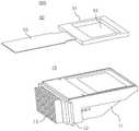
图1是表示本发明的HUD装置的基本结构及其影像显示装置的内部结构的一例的图。FIG. 1 is a diagram showing an example of the basic structure of the HUD device and the internal structure of the video display device of the present invention.
图2是说明解决本发明的现有技术中的问题的原理的图。FIG. 2 is a diagram illustrating the principle of solving the problems in the prior art of the present invention.
图3是表示本发明实施例1的影像显示装置的光源装置的外观的展开立体图。3 is a developed perspective view showing an appearance of a light source device of the video display device according to
图4是表示本发明实施例1的方式的影像显示装置的光源装置的光学系统概观的立体图。4 is a perspective view showing an overview of the optical system of the light source device of the video display device according to the first embodiment of the present invention.
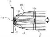
图5是详细说明实施例1的影像显示装置中的准直器的截面图。5 is a cross-sectional view illustrating in detail the collimator in the video display device of the first embodiment.
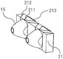
图6是表示实施例1的影像显示装置中的准直器和偏振变换元件的配置结构的立体图。6 is a perspective view showing an arrangement configuration of a collimator and a polarization conversion element in the video display device of Example 1. FIG.
图7是表示实施例1的影像显示装置中,配置于偏振变换元件的出射面的合成扩散块的立体图。7 is a perspective view showing a synthesis diffusion block arranged on an output surface of a polarization conversion element in the video display device of Example 1. FIG.
图8是表示实施例1的影像显示装置中的导光体的详情的立体图、截面图和局部放大截面图。8 is a perspective view, a cross-sectional view, and a partially enlarged cross-sectional view showing details of a light guide body in the video display device of Example 1. FIG.
图9是表示构成实施例1的影像显示装置中的导光体的反射面和连接面以及光线反射的详情的放大截面图。9 is an enlarged cross-sectional view showing details of a reflection surface and a connection surface constituting a light guide body and light reflection in the image display device of Example 1. FIG.
图10是表示实施例1的影像显示装置中的结构和光线的状态的俯视图和侧视截面图。10 is a plan view and a side cross-sectional view showing the structure and the state of light in the image display device of Example 1. FIG.
图11是表示用于说明实施例1的影像显示装置中的导光体的作用的比较例的图。FIG. 11 is a diagram showing a comparative example for explaining the function of the light guide in the video display device of Example 1. FIG.
图12是说明实施例1的影像显示装置的导光体成型用的模具的加工方法的图。12 is a diagram illustrating a method of processing a mold for molding a light guide body of the video display device of Example 1. FIG.
图13是表示构成实施例1的影像显示装置中的导光体的反射面和连接面以及光线反射的设定的一例的放大截面图。13 is an enlarged cross-sectional view showing an example of the setting of the reflection surface and the connection surface constituting the light guide body and the light reflection in the image display device of the first embodiment.
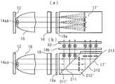
图14是表示本发明的其他实施例的影像显示装置中的结构和光线的状态的俯视图和侧视截面图。14 is a plan view and a side cross-sectional view showing the structure and the state of light in the video display device according to another embodiment of the present invention.
具体实施方式Detailed ways
下面,参照附图对本发明的实施方式进行详细说明。Hereinafter, embodiments of the present invention will be described in detail with reference to the accompanying drawings.
<HUD的基本结构和本发明的原理><Basic structure of HUD and principle of the present invention>
图1(a)表示本发明的HUD装置的基本结构。从该图可明确看出,HUD装置100基本上具有影像显示装置300,该影像显示装置300包括由投影仪、LCD(Liquid Crystal Display:液晶显示器)等构成的光源装置,HUD装置100利用反射镜151(例如,具有自由曲面反射镜或光轴非对称的形状的反射镜等)、其他反射镜152将来自该影像显示装置的光(此情况下为影像光)反射而投射至车辆102的挡风玻璃103或配置于其跟前的组合器200上。另一方面,驾驶员105通过观察挡风玻璃103或组合器200上投射的影像,透过透明的挡风玻璃103在其前方将上述影像识别为虚像。此时,也可以将反射镜151置换为凹面反射镜,将其他反射镜152置换为冷光反射镜。此处,为了避免重复说明,对将影像光投射至组合器200上的例子进行说明。Fig. 1(a) shows the basic structure of the HUD device of the present invention. As is clear from this figure, the
图1(b)表示上述HUD装置100、特别是其影像显示装置300的内部结构的一例。从该图可明确看出,表示影像显示装置300构成投影仪的情况,影像显示装置300例如具有光源301、照明光学系统302和显示元件303等各部分。此外,作为该光源301,通过采用以下详述的本发明的光源装置,能够生成投射用的良好的照明光。FIG. 1( b ) shows an example of the internal structure of the above-described
此外,在该例中,包括:将光源301生成的照明光聚光且更均匀地照射至显示元件303的光学系统即照明光学系统302和生成所投射的影像的元件即显示元件303。但是,这些构成要素在下面描述的实施例中,如图4所示,在本发明的光源装置(参照图3的光源装置壳11)内包括合成扩散块16、第一扩散板18a、导光体17、第二扩散板18b以及液晶显示面板52。因此,可直接将本发明的光源装置10(参照图3)用作HDU装置100的影像显示装置300。据此,可容易地安装在特别是像车辆内的仪表器这样的狭小空间内的HUD装置100得以实现。此外,从上述影像显示装置300出射的光进而经显示距离调节机构400、反射镜驱动部500被投射于车辆102的挡风玻璃103或组合器200,这对本领域技术人员而言是显而易见的。In addition, in this example, the illumination
接着,参照图2,在本发明中,说明用于解决上述问题即当驾驶员佩戴具有偏振作用的太阳镜(下面也称为“偏光太阳镜”)时,因来自HUD装置100的直线偏振光而看不见车辆102的挡风玻璃103或组合器200上显示的虚像这样的问题的原理。在该图中,表示将来自HUD装置100的影像光显示在组合器200上来代替显示在挡风玻璃103上的例子,但是,对本领域技术人员而言,很明显将来自HUD装置100的影像光投射至挡风玻璃103上的情况下也是同样的。Next, referring to FIG. 2 , in the present invention, a description will be given to solve the above-mentioned problem, that is, when the driver wears sunglasses with polarization (hereinafter also referred to as “polarized sunglasses”), the driver will see the problem due to the linearly polarized light from the
组合器200例如是在由聚碳酸酯板、玻璃板等透明的板状部件构成的基板210的表面(与驾驶员侧相对的面,图中为右侧面)形成有高分子膜220的器件。该高分子膜220是如图中虚线的椭圆所示,由高分子形成的双折射椭圆体按规定的方向排列而成的膜。图中的附图标记230表示安装于基板210的背面的半反射镜,附图标记240表示在高分子膜220的表面即组合器200的最表面侧形成的防反射(AR)膜。The
关于这样的组合器200,如图中的实线的箭头所示,在来自HUD装置100的S偏振的影像光入射至该组合器200的情况下,对于此情况下的入射光,在法线截面高分子膜220的双折射椭圆体的主轴与偏振面之间的关系如图2的左下所示。即,高分子膜220的安装成,作为其光学主轴的双折射椭圆体的主轴的朝向与入射至组合器200的光的偏振面一致。Regarding such a
依照上述的结构,入射至组合器200的光沿着高分子膜220的主轴,保持直线偏振地传播。其结果是,由于使S偏振的直线偏振光入射至半反射镜230面,因此,半反射镜能够以高反射率将构成HUD的图像的光线反射。According to the above structure, the light incident on the
之后,光线被基板210背面的半反射镜230反射,再次入射至高分子膜220。另一方面,在该高分子膜220,对于来自组合器200的反射光,因光的行进方向改变,在反射光的法线截面高分子膜220的主轴与偏振面之间的关系如图2的右下所示,角度彼此不同。因此,半反射镜230反射的直线偏振光随着在高分子膜220内传播,受到高分子膜的延迟的影响而变成椭圆偏振。After that, the light is reflected by the
即,来自HUD装置100的S偏振的影像光,因构成组合器200的高分子膜220的作用,在到达驾驶员的眼中时成为椭圆偏振光而入射。通常的偏光太阳镜由于拦截路面的强光、挡风玻璃的反射光,因此,对于路面、挡风玻璃具有拦截S偏振的偏振光的特性。因此,在现有的通常的HUD光学系统中,由于佩戴偏光太阳镜而无法识别HUD影像,但在本发明中,因为在挡风玻璃或组合器发生反射的HUD影像的光被变换成椭圆偏振光,所以即使在戴上偏光太阳镜的状态下也能够识别HUD影像。That is, the S-polarized video light from the
在上述例子中,作为用于将S偏振的影像光变换成椭圆偏振光的一个技术手段,描述了由高分子形成的双折射椭圆体沿规定的方向排列而成的高分子膜220,但本发明不限于此,也可利用具有与上述技术手段同样的效果的技术手段。关于上述的偏振变换单元的位置,在上述说明中,该高分子膜220形成于组合器200的基板210的表面(与驾驶员侧相对的面)。但是,本发明不限于此,虽然挡风玻璃或组合器的反射率会稍微降低,该偏振变换单元也可配置于来自影像显示装置300的偏振的影像光的传播光路,更具体地说,可配置于从液晶显示面板52的影像光出射面至组合器200(或挡风玻璃103)的内侧表面的光路的一部分。In the above example, as a technical means for converting S-polarized image light into elliptically polarized light, the
关于上述高分子膜的制造方法,通过使用耐热性高的例如金属板等夹住聚碳酸酯等光弹性比较大的膜,一边加热至t℃,一边施加剪切应力,这样进行制作。上述t℃优选为高分子膜的热软化点温度以上,且期望低于熔融溶融。这里,将聚碳酸酯作为高分子膜,使加热温度为127℃。高分子膜的制造方法不限于此,可根据材料、特性进行适当选择。The production method of the polymer film described above is produced by sandwiching a relatively photoelastic film such as polycarbonate with a metal plate having high heat resistance, and applying shear stress while heating to t°C. The above-mentioned t°C is preferably equal to or higher than the thermal softening point temperature of the polymer film, and desirably lower than the melting point. Here, polycarbonate was used as the polymer film, and the heating temperature was 127°C. The manufacturing method of a polymer film is not limited to this, According to a material and a characteristic, it can select suitably.
另外,在HUD装置中,需要顾虑太阳光自身对HUD装置的损害。如图2中粗的虚线即光线401所示,当太阳处于特定的方向(图2中为相对于组合器200的反射面成θ角的方向)时,其光线如光线401p所示,沿HUD影像光的光路逆行而到达影像显示装置300,因此影像显示装置可能会受到损害。In addition, in the HUD device, it is necessary to consider the damage of the sunlight itself to the HUD device. As shown by the thick dotted line in Fig. 2, namely
在本发明中,为了避免上述损害,对于如上述那样以入射角θ从外部入射至组合器的光,使半反射镜230对S偏振光的反射率为50%以上。通过采用本结构,太阳光相对于组合器面的S偏振光的50%以上的部分如光线401s所示,向外部反射,剩余部分成为光线401p,沿HUD影像光的光路逆行。光线401s的S偏振光、P偏振光成分与HUD影像光同样地与上述高分子膜的双折射椭圆体的主轴平行或正交,因此,保存偏振状态地传播。之后,被图1所示的反射镜151反射,进而被其他反射镜152反射后,入射至影像显示装置300。此处,其他反射镜152对可见光的反射率高,对红外光的反射率低,为所谓的冷光镜(Cold mirror)的结构,进而具有这样的偏振光特性,即,可见光域的S偏振光的反射率高达90%以上,对P偏振光的反射率在30%以下。采用本结构,光线401p的P偏振光成分的大部分如图所示透过其他反射镜152而不会到达影像显示装置300。为了具有上述的偏振光特性,优选主要光线对于其他反射镜152的入射角ψ为30度以上。如果主要光线的入射角度小于30度,则难以实现偏振方向导致的充分的反射率特性变化。通过采用本结构,对于组合器面,大部分的P偏振光成分被拦截,剩余的S偏振光成分为主体。因此,到达影像显示装置300的太阳光,相比于入射至组合器200的可见光域的太阳光,P偏振光成分在30%以下,S偏振光成分在50%以下,即平均为40%以下。另外,红外光因上述其他反射镜152,大部分红外光被拦截,能够大幅度地降低太阳光对影像显示装置300的损害。In the present invention, in order to avoid the above-mentioned damage, the reflectance of the
另一方面,HUD影像光从上述显示元件303向组合器200以S偏振光出射,因此,在上述其他反射镜152,反射90%以上的可见光线,上述其他反射镜152对影像光的影响小。另外,代替使上述其他反射镜152具有上述的偏振光特性,在组合器200与影像显示装置300之间设置将对于组合器200为P偏振光的偏振光拦截的偏振光滤光器,能够得到同样的效果,但在图中未示出这样的结构。进而,半反射镜230通过将电介质多层膜层叠规定的层数,能够实现上述特性。以上描述了使用组合器的情况下保护HUD装置不受太阳光损害的对策,本领域技术人员明显可知,在代替组合器使用挡风玻璃反射影像光的情况下,在该挡风玻璃的外部表面实施与上述的对策同样的对策即可。On the other hand, the HUD image light is emitted from the above-mentioned
<影像显示装置的详细结构><Detailed structure of video display device>
接着,在下面详细说明在HUD装置100内射出S偏振的影像光的影像显示装置300的结构,特别是适用于模块化且用于实现光利用效率高的小型HUD装置的结构。Next, the structure of the
图3是表示本发明的一个实施方式的影像显示装置300的概观的展开立体图。从图中可以看出,影像显示装置(主体)300例如由塑料等形成,由内部收纳有稍后详述的LED、准直器、合成扩散块、导光体等的光源装置壳11构成。在其上表面安装有液晶显示元件50。在光源装置壳11的一个侧面上安装有LED基板12,该LED基板12安装有作为半导体光源的LED(Light Emitting Diode:发光二极管)元件及其控制电路,在该LED基板12的外侧面安装有用于冷却上述LED元件及控制电路产生的热量的散热器13。3 is a developed perspective view showing an overview of a
安装于光源装置壳11的上表面的液晶显示元件50,由液晶显示面板框架51、安装于该框架的液晶显示面板52和与该面板电连接的FPC(Flexible Printed Circuits:柔性配线基板)53构成。即,液晶显示面板52与作为固体光源的LED元件一起,基于来自构成电子装置的控制电路(此处未图示)的控制信号,生成并控制所要显示的影像,关于这点,在后面进行详细说明。The liquid
下面,参照作为附图的图4~图13详细地说明上述影像显示装置300的内部,即,光源装置壳11内收纳的光学系统的结构。Next, the inside of the above-mentioned
在图4中,构成光源的多个(在本例中为2个)LED14a、14b(此处未图示出)相对于LED准直器15安装于规定的位置。该LED准直器15分别例如由聚碳酸酯等透光性的树脂形成。而且,该LED准直器15也如图5所示,具有使大致抛物截面旋转而得到的圆锥凸形状的外周面156,并且,在其顶部,具有在中央部形成有凸部(即凸透镜面)157的凹部153。在其平面部的中央部具有向外侧凸出的凸透镜面(或也可以是向内侧凹陷的凹透镜面)154。形成LED准直器15的圆锥形状的外周面的抛物面(外周面)156,在可将从LED14a或14b向周边方向射出的光在其内部进行全反射的角度范围内设定,或者形成有反射面。In FIG. 4 , a plurality of (two in this example)
另一方面,LED14a、14b分别配置于其电路基板即所谓的LED基板12的表面上的规定位置。根据图5明显可知,该LED12基板相对于LED准直器15被配置并固定成,其表面上的LED14a或14b分别位于凹部153的中央部。On the other hand, LED14a, 14b is arrange|positioned at the predetermined position on the surface of the so-called
采用上述的结构,利用上述LED准直器15,从LED14a或14b发射的光中,尤其是从其中央部分向上方(图的右方向)发射的光如图中箭头所示,被形成LED准直器15的外形的两个凸透镜面157、154聚光而成为平行光,而从其他部分向周边方向射出的光被形成LED准直器15的圆锥形状的外周面的抛物面(外周面)156反射,因此,同样地被聚光而成为平行光。换言之,采用在中央部构成凸透镜并且在周边部形成有抛物面(外周面)156的LED准直器15,可将由LED14a或14b发出的几乎全部的光作为平行光取出,可提高产生的光的利用效率。With the above-mentioned structure, using the above-mentioned
在该LED准直器15的光的射出侧设置有下面详述的偏振变换元件21。该偏振变换元件21如图6所示,将截面为平行四边形的柱状(下面,称为平行四边形柱)的透光性部件和截面为三角形的柱状(下面,称为三角形柱)的透光性部件组合,与相对于来自LED准直器15的平行光的光轴正交的面平行且呈阵列状地排列多个而构成。进而,在这些呈阵列状地排列的相邻的透光性部件间的界面处,交替地设置有偏振分束器(下面简称为“PBS”)膜211和反射膜212,并且,在向偏振变换元件21入射而透过PBS膜211的光的出射面,设置有1/2λ相位板213。The
在该偏振变换元件21的出射面,进而设置有图7所示的矩形的合成扩散块16。即,从LED14a或14b射出的光,由于LED准直器15的作用成为平行光而入射至合成扩散块16,被出射侧(即,射出侧)的纹理结构部(texture)161扩散后,到达下面所述的导光体17。A rectangular
返回上述图4,在上述合成扩散块16的出射面侧,隔着第一扩散板18a设置有截面大致为三角形的角柱状的导光体17,在其上表面安装有第二扩散板18b。通过采用这样的结构,上述LED准直器15的水平光由于该导光体17的作用而被向图的上方反射,被引导至上述液晶显示元件50的入射面。此时,利用上述第一以及第二扩散板18a、18b,使入射光的强度均匀。Returning to FIG. 4 , a
下面,参照附图对构成上述影像显示装置300的导光体17进行详细说明。图8(a)是表示该导光体17整体的立体图,图8(b)是表示其截面的图,图8(c)和图8(d)是表示截面的详情的局部放大截面图。Next, the
导光体17例如是使用丙烯酸等透光性树脂形成为截面大致为三角形(参照图8(b))的棒状的部件,而且,从图4和图8(a)可知,包括:隔着第一扩散板18a与上述合成扩散块16的出射面相对的导光体光入射部(面)171、形成斜面的导光体光反射部(面)172和隔着第二扩散板18b与上述液晶显示元件50的液晶显示面板52相对的导光体光射出部(面)173。The
在该导光体17的导光体光反射部(面)172,如作为其局部放大图的图8(c)和(d)所示,交替且呈锯齿状地形成有大量的反射面172a和连接面172b。反射面172a(图中右上去的线段)相对于图中点划线所示的水平面形成有αn(n为自然数,在本例中例如为1~130),作为其一例,此处,将αn设定为43度以下(但在0度以上)。In the light guide body light reflection part (surface) 172 of the
另一方面,连接面172b(图中右下去的线段)相对于反射面形成有βn(n为自然数,在本例中例如为1~130)。即,反射部的连接面172b对于入射光以在后述的散射体的半值角的范围内呈现阴影的角度倾斜。α1、α2、α3、α4……形成反射面仰角,β1、β2、β3、β4……形成反射面与连接面的相对角度,作为其一例,设定为90度以上(但在180度以下),关于这一点,稍后进行详细说明。在本例中,β1=β2=β3=β4=……=β122=……β130。On the other hand, βn (n is a natural number, for example, 1 to 130 in this example) is formed on the connecting
图9和图10为了方便说明,表示使反射面172a和连接面172b的大小相对于导光体17相对地增大了的示意图。在导光体17的导光体光入射部(面)171,主要光线向相对于反射面172a入射角变大的方向偏转了δ(参照图10(b))。即,导光体光入射部(面)171形成为向光源侧倾斜的弯曲的凸形状。通过采用这样的结构,来自合成扩散块16的出射面的平行光经第一扩散板18a扩散而入射,从图中可以看出,由于导光体光入射部(面)171而向上方稍微折弯(偏转),到达导光体光反射部(面)172(参照图11的比较例)。9 and 10 are schematic diagrams in which the sizes of the
在该导光体光反射部(面)172,大量的反射面172a和连接面172b交替且呈锯齿状形成,扩散光在各个反射面172a上被全反射而朝向上方行进,进而,经导光体光射出部(面)173和图4所示的第二扩散板18b作为平行的扩散光入射至液晶显示元件50的液晶显示面板52。因此,反射面仰角α1、α2、α3、α4……设定为,各个反射面172a相对于上述扩散光为临界角以上的角度,另一方面,反射面172a与连接面172b的相对角度β1、β2、β3、β4……如上所述那样设定为规定的角度,更优选设定为90度以上的角度(βn≥90度),其理由稍后详述。In this light guide light reflecting portion (surface) 172, a large number of reflecting
通过采用上述的结构,各反射面172a相对于上述扩散光总是为临界角以上的角度,因此,即使在导光体光反射部(面)172不形成金属等反射膜,也能进行全反射,能够实现低成本的光源装置。另一方面,如作为比较例的图11所示,在导光体17的导光体入射部主要的光线没有发生折弯(偏转)的情况下,扩散光的一部分相对于反射面172a为临界角以下,无法确保充分的反射率,因此,无法实现良好特性的(明亮的)光源装置。By adopting the above-described structure, each reflecting
另外,反射面仰角α1、α2、α3、α4……为随着从导光体光反射部(面)172的下部向上部移动而逐一稍微增加的值。这是为了实现这样的结构,由于透过液晶显示元件50的液晶显示面板52的光具有一定程度的发散角,因此尤其是透过液晶显示面板52的周边部的光的一部分照射在配置于下游的反射镜的周缘,即所谓周边减光,为了防止周边减光的发生,如图9的光线30所示,使周边部的光线稍微向中心轴方向偏转。In addition, the reflection plane elevation angles α1, α2, α3, α4 . . . are values that slightly increase one by one as they move from the lower part to the upper part of the light guide light reflection part (surface) 172 . This is to realize such a configuration. Since the light passing through the liquid
如上所述,构成为了β1=β2=β3=β4……βn≥90度,之所以采用这样的结构,是为了如图12所示,在用于通过注射成型(Injection Molding)制作导光体17的模具40的加工中,能够利用底面与侧面的相对角度为β的立铣刀35,同时加工反射面172a和连接面172b。另外,由于相对于反射面172a和连接面172b,能够使用相对粗的工具进行加工,因此能够大幅度地缩短加工时间,大幅度地降低加工费。并且,能够高精度地加工反射面172a与连接面172b的边界边缘,能够提高导光体17的导光特性。As described above, β1 = β2 = β3 = β4... In the machining of the
图9中的Lr1、Lr2、Lr3、Lr4……表示反射面172a相对于水平面的投影长度,Lc1、Lc2、Lc3、Lc4……表示连接面172b相对于水平面的投影长度,Lr/Lc即反射面172a与连接面172b之比可根据位置而改变。入射至导光体17的主要光线30的强度分布不一定与液晶显示面板52的入射面所希望的强度分布一致。于是,采用根据反射面172a与连接面172b之比Lr/Lc,调节强度分布的结构。而且,该比越高,越能够提高使该部分的反射光的平均强度。一般而言,入射至导光体的光线30在中央部变强,为了纠正这一点,使上述比Lr/Lc根据位置而不同,尤其是,使中央部变小。由于为上述比Lr/Lc根据位置而不同并且上述反射面仰角α1、α2、α3、α4……根据位置而不同的结构,因此,表示导光体光反射部(面)172的大致形状的包络线172c如图9所示为曲线形状。In FIG. 9, Lr1, Lr2, Lr3, Lr4...represent the projected lengths of the
进而,构成为了Lr1+Lc1=Lr2+Lc2=Lr3+Lc3=Lr4+Lc4……=Lr+Lc≤0.6mm。通过采用这样的结构,能够使从导光体17的导光体光射出部(面)173观看到的反射面的重复间距相同。由于该间距为0.6mm以下,因此,结合扩散板18a、18b的作用/效果,在经液晶显示面板52观察的情况下,各个出射面不分离,看起来为连续面,因此,能够实现经液晶显示面板52观看时的空间亮度的均匀化,因此,显示特性提高。即,依照本结构,能够使液晶显示面板52上的入射光强度分布均匀化。另一方面,当Lr+Lc之值小于0.2mm时,不仅耗费加工时间,还难以高精度地加工各反射面172a,因此优选Lr+Lc之值为0.2mm以上。Furthermore, Lr1+Lc1=Lr2+Lc2=Lr3+Lc3=Lr4+Lc4 ......=Lr+Lc≦0.6 mm. By adopting such a structure, the repetition pitch of the reflection surfaces seen from the light guide body light emitting portion (surface) 173 of the
依照上述导光体17的导光体光反射部(面)172的形状,能够满足主要光的全反射条件,无需在上述导光体光反射部(面)172设置铝等反射膜,能够高效地反射光,也无需进行会导致制造成本上升的氧化铝薄膜的蒸镀操作等,能够实现成本更低的明亮的光源。另外,将各相对角β设定为连接面172b相对于主要光线30因合成扩散块16和扩散板18a而扩散了的光成为阴影(被遮蔽)的角度。通过采用这样的结构,通过抑制不需要的对连接面172b的光的入射,能够降低不需要的光的反射,能够实现特性良好的光源装置。According to the shape of the light guide light reflection part (surface) 172 of the
另外,依照上述导光体17,特别是,通过适当地设定反射面仰角α1、α2、α3、α4……,能够自由地改变光轴方向上的导光体光射出部(面)173的长度,因此,能够实现相对于导光体光入射部(面)171,可将导光体光射出部(面)173的大小(面尺寸)改变为适于上述液晶显示面板52等装置的适宜的所需的大小(面尺寸)的光源装置。关于这一点,由于不依赖于构成光源的LED14a、14b的配置形状即可使导光体光射出部(面)173为期望的大小,因此能够得到期望的大小的面状发光源。进而,还能够确保包括构成光源的LED14a、14b的配置在内的设计的自由度,有利于装置整体的小型化。In addition, according to the above-mentioned
不仅如此,依照上述导光体17,如图13所示,通过适当地设定构成导光体光反射部(面)172的连接面172b(在此例中,构成为在其中央部的一部分的反射面172a不反射光),能够在导光体17的导光体光射出部(面)173,根据位置改变反射面172a与连接面172b之比Lr/Lc。图示的例子表示,导光体17的导光体光射出部(面)173的光显示,在光轴的方向上左右分开的样子。此情况尤其适用于在HUD装置中将虚像画面上下或左右分开显示的情况等。Furthermore, according to the above-mentioned
此处,入射至液晶显示面板52的主要光线的倾斜通常期望接近垂直,但是,根据液晶显示面板的特性,如图10(b)所示,也可倾斜角度η。即,在市售的液晶显示面板中,有使入射角倾斜5~15度左右时特性良好的液晶显示面板,在此情况下,优选根据其特性使上述η为5~15度。Here, the inclination of the main light rays incident on the liquid
另外,代替使液晶显示元件50倾斜η,通过调节反射面172a的角度,也可使射向液晶显示面板52的主要光线的倾斜度倾斜。进而,在需要使上述光线的倾斜度向导光体的侧面方向倾斜的情况下,可通过使在合成扩散块16的出射面形成的三角形状的纹理结构部161的斜面倾斜度为左右非对称、或改变由反射面172a、172b构成的纹理结构部的形成方向来实现。In addition, instead of tilting the liquid
如以上详述的那样,依照本发明的影像显示装置300,能够进一步提高来自光源的光的光利用效率其其均匀的照明特性,并且能够作为模块化的光源装置小型且低成本地制造。As described in detail above, according to the
即,依照上述影像显示装置300,由于利用上述的偏振变换元件21使入射至构成液晶显示元件50的液晶显示面板52的光成为S偏振光波,因此,可提高该光在液晶显示面板52中的透射率(透过率)。因此,能够利用更少的发光源(LED),能够更廉价地实现更小型且高效率的模块化光源装置。上述说明中,将偏振变换元件21安装于LED准直器15之后,但是,本发明不限于此,本领域技术人员明显可知,将偏振变换元件21设置在至液晶显示元件的光路中,也能够得到同样的作用/效果。That is, according to the
<其他实施例><Other Examples>
如图14所示,也可以代替通常的透光性树脂,由偏振变换元件构成(导光体17’),即,由偏振变换元件构成配置于合成扩散块16的后方的导光体17。在该结构中,从图中可以看出,组合三角形柱的透光性部件211’和平行四边形柱的透光性部件212’,在它们的边界面,反射从LED14a或14b射出后经LED准直器15成为了平行光的入射光的S偏振光波(参照图中的记号(×)),另一方面,形成P偏振光波(参照图中的上下箭头)透过的PBS膜211,并且,在平行四边形柱的透光性部件212’的上表面形成有1/2λ相位板213,在其侧面形成有反射膜212。As shown in FIG. 14 , instead of the usual light-transmitting resin, a polarization conversion element (light guide 17') may be used, that is, the
依照上述结构,从图中可以看出,从LED14a或14b射出后经LED准直器15成为了平行光的入射光,因代替导光体17由偏振变换元件构成的导光体17’而成为S偏振光波,从该元件的上表面向上方射出。即,在上述的结构中,特别是通过除去由通常的透光性树脂构成的导光体17,能够实现装置的大幅度小型化以及装置的制造成本的降低。According to the above-mentioned structure, it can be seen from the figure that the incident light which is emitted from the
上面,说明了各种本发明实施例的影像显示装置的结构,该影像显示装置用于实现适于模块化的、小型且光利用效率高的HUD装置。但是,如下所述的内容与上述是相同的,即,对于挡风玻璃或组合器,来自该影像显示装置的S偏振的影像光因构成挡风玻璃或组合器的高分子膜220的作用,到达驾驶员的眼中的影像光被变换成椭圆偏振光,由此,即使在戴上偏光太阳镜的状态下也能识别HUD影像。The structure of the video display device according to various embodiments of the present invention has been described above, and the video display device is used to realize a HUD device suitable for modularization, small size, and high light utilization efficiency. However, the following content is the same as the above, that is, for the windshield or the combiner, the S-polarized image light from the image display device is due to the action of the
上面,对各种实施例进行了详述,但是,本发明不限于上述实施例,包含各种变形例。例如,上述实施例为了使本发明易于理解而对整个装置进行了详细说明,但不限定于具备所说明的全部结构。可将某实施例的结构的一部分置换为其他实施例的结构,另外,也可在某实施例的结构上添加其他实施例的结构。另外,关于各实施例的结构的一部分,可进行其他结构的增加/删除/置换。The various embodiments have been described in detail above, but the present invention is not limited to the above-described embodiments and includes various modifications. For example, in the above-mentioned embodiments, the entire apparatus has been described in detail in order to facilitate the understanding of the present invention, but it is not limited to having all the structures described. A part of the structure of a certain embodiment may be replaced with the structure of another embodiment, and the structure of another embodiment may be added to the structure of a certain embodiment. In addition, addition/deletion/replacement of other structures may be performed with respect to a part of the structures of the respective embodiments.
附图标记的说明Explanation of reference numerals
100HUD装置、300影像显示装置、102车辆、103挡风玻璃、200组合器、210基板、220高分子膜、230半反射镜、50液晶显示元件、10光源装置、11光源装置壳、12LED基板、13散热器、50液晶显示元件、51液晶显示面板框架、52液晶显示面板、53FPC(柔性配线基板)、14a、14b LED、15LED准直器、17导光体、18a、b扩散板、172a反射面、172b连接面、16合成扩散块、161纹理结构部、21偏振变换元件、211PBS膜、212反射膜、151反射镜、152其他反射镜。100HUD device, 300 video display device, 102 vehicle, 103 windshield, 200 combiner, 210 substrate, 220 polymer film, 230 half mirror, 50 liquid crystal display element, 10 light source device, 11 light source device case, 12 LED substrate, 13 radiator, 50 liquid crystal display element, 51 liquid crystal display panel frame, 52 liquid crystal display panel, 53 FPC (flexible wiring board), 14a, 14b LED, 15LED collimator, 17 light guide body, 18a, b diffuser plate, 172a Reflective surface, 172b connection surface, 16 synthetic diffuser, 161 textured structure, 21 polarization conversion element, 211 PBS film, 212 reflective film, 151 mirror, 152 other mirrors.
Claims (10)
Translated fromChinesePriority Applications (1)
| Application Number | Priority Date | Filing Date | Title |
|---|---|---|---|
| CN202210935476.9ACN115128814B (en) | 2016-09-06 | 2017-08-01 | Head-up display |
Applications Claiming Priority (5)
| Application Number | Priority Date | Filing Date | Title |
|---|---|---|---|
| JP2016-173548 | 2016-09-06 | ||
| JP2016173548 | 2016-09-06 | ||
| PCT/JP2017/027834WO2018047522A1 (en) | 2016-09-06 | 2017-08-01 | Head-up display device and video display device therefor |
| CN201780054622.4ACN109661606B (en) | 2016-09-06 | 2017-08-01 | Head-up display and image display device used by same |
| CN202210935476.9ACN115128814B (en) | 2016-09-06 | 2017-08-01 | Head-up display |
Related Parent Applications (1)
| Application Number | Title | Priority Date | Filing Date |
|---|---|---|---|
| CN201780054622.4ADivisionCN109661606B (en) | 2016-09-06 | 2017-08-01 | Head-up display and image display device used by same |
Publications (2)
| Publication Number | Publication Date |
|---|---|
| CN115128814Atrue CN115128814A (en) | 2022-09-30 |
| CN115128814B CN115128814B (en) | 2023-09-15 |
Family
ID=61561790
Family Applications (2)
| Application Number | Title | Priority Date | Filing Date |
|---|---|---|---|
| CN201780054622.4AActiveCN109661606B (en) | 2016-09-06 | 2017-08-01 | Head-up display and image display device used by same |
| CN202210935476.9AActiveCN115128814B (en) | 2016-09-06 | 2017-08-01 | Head-up display |
Family Applications Before (1)
| Application Number | Title | Priority Date | Filing Date |
|---|---|---|---|
| CN201780054622.4AActiveCN109661606B (en) | 2016-09-06 | 2017-08-01 | Head-up display and image display device used by same |
Country Status (4)
| Country | Link |
|---|---|
| US (1) | US11571952B2 (en) |
| JP (2) | JP6638077B2 (en) |
| CN (2) | CN109661606B (en) |
| WO (1) | WO2018047522A1 (en) |
Families Citing this family (20)
| Publication number | Priority date | Publication date | Assignee | Title |
|---|---|---|---|---|
| JP7000937B2 (en)* | 2018-03-16 | 2022-01-19 | 株式会社リコー | Display devices and equipment |
| JP7117066B2 (en)* | 2019-02-15 | 2022-08-12 | マクセル株式会社 | Vehicle information display device and vehicle information display system |
| CN210072208U (en)* | 2019-05-29 | 2020-02-14 | 3M创新有限公司 | display device |
| CN112444973A (en)* | 2019-09-02 | 2021-03-05 | 未来(北京)黑科技有限公司 | Head-up display device |
| JP6972423B2 (en)* | 2019-09-11 | 2021-11-24 | 日本化薬株式会社 | Image display system and head-up display system |
| WO2021070789A1 (en)* | 2019-10-10 | 2021-04-15 | 株式会社小糸製作所 | Lens component and light source module |
| US11235706B2 (en)* | 2019-10-30 | 2022-02-01 | Panasonic Intellectual Property Management Co., Ltd. | Display system |
| CN110989173A (en)* | 2019-12-27 | 2020-04-10 | 厦门天马微电子有限公司 | Display system |
| CN113126296B (en)* | 2020-01-15 | 2023-04-07 | 未来(北京)黑科技有限公司 | Head-up display equipment capable of improving light utilization rate |
| JP7332495B2 (en)* | 2020-01-31 | 2023-08-23 | マクセル株式会社 | VEHICLE INFORMATION DISPLAY SYSTEM AND INFORMATION DISPLAY SYSTEM |
| JP7409953B2 (en)* | 2020-04-27 | 2024-01-09 | マクセル株式会社 | Light source device and head-up display device |
| EP4147088A4 (en)* | 2020-05-08 | 2024-06-12 | 3M Innovative Properties Company | Display system for vehicle |
| US12181666B2 (en)* | 2020-05-25 | 2024-12-31 | Samsung Electronics Co., Ltd. | System of virtual image projection on screen with effect of eliminating influence of solar radiation |
| CN114063284A (en)* | 2020-07-30 | 2022-02-18 | 未来(北京)黑科技有限公司 | Image sources, head-up displays, and transportation equipment |
| CN114137725A (en)* | 2020-09-04 | 2022-03-04 | 未来(北京)黑科技有限公司 | A head-up display system capable of displaying three-dimensional images |
| CN114252993A (en)* | 2020-09-23 | 2022-03-29 | 未来(北京)黑科技有限公司 | Visual image display device, vehicle and main control system |
| CN114252992A (en)* | 2020-09-23 | 2022-03-29 | 未来(北京)黑科技有限公司 | Head-up display device, motor vehicle and control system |
| CN115097672A (en)* | 2022-07-25 | 2022-09-23 | 业成科技(成都)有限公司 | Backlight module, image generation unit, head-up display and vehicle |
| US12399361B2 (en)* | 2023-01-11 | 2025-08-26 | Infineon Technologies Ag | Distributed optical architecture for vehicle head up display |
| WO2024195934A1 (en)* | 2023-03-23 | 2024-09-26 | 엘지전자 주식회사 | Vehicle image-device having sunlight-avoidance structure |
Citations (16)
| Publication number | Priority date | Publication date | Assignee | Title |
|---|---|---|---|---|
| JPH06273691A (en)* | 1993-03-24 | 1994-09-30 | Nissan Motor Co Ltd | Head-up type vehicle display device |
| JPH08169254A (en)* | 1994-12-19 | 1996-07-02 | Asahi Glass Co Ltd | Holographic display device |
| JP2001004953A (en)* | 1999-06-18 | 2001-01-12 | Asahi Glass Co Ltd | Display device for vehicles |
| CN1362633A (en)* | 2000-12-28 | 2002-08-07 | Lg电子株式会社 | Projector |
| TW200935090A (en)* | 2008-02-04 | 2009-08-16 | Ind Tech Res Inst | Display system |
| CN102998839A (en)* | 2012-12-10 | 2013-03-27 | 友达光电股份有限公司 | Head-up display |
| US20130279016A1 (en)* | 2010-12-23 | 2013-10-24 | Eckhard Finger | Head-up display for a motor vehicle |
| DE102012210503A1 (en)* | 2012-06-21 | 2013-12-24 | Bayerische Motoren Werke Aktiengesellschaft | Unification optics of a head-up display and head-up display |
| TW201409074A (en)* | 2012-08-30 | 2014-03-01 | Coretronic Corp | Head up display |
| CN103792662A (en)* | 2014-01-15 | 2014-05-14 | 深圳市矽韦氏科技有限公司 | Double-image-eliminating head-up display device |
| CN203688913U (en)* | 2014-01-15 | 2014-07-02 | 深圳市矽韦氏科技有限公司 | Anti-ghost head-up display device |
| WO2015092867A1 (en)* | 2013-12-17 | 2015-06-25 | パイオニア株式会社 | Virtual-image generation element and heads-up display |
| WO2015125247A1 (en)* | 2014-02-20 | 2015-08-27 | パイオニア株式会社 | Projection device |
| WO2015177833A1 (en)* | 2014-05-19 | 2015-11-26 | パイオニア株式会社 | Virtual image generating element and head-up display |
| JP2015225236A (en)* | 2014-05-28 | 2015-12-14 | 株式会社デンソー | Projection member, head-up display device, and polarized sunglass |
| US20160091716A1 (en)* | 2014-09-29 | 2016-03-31 | Honeywell International Inc. | Apparatus and method for supressing double images on a combiner head-up display |
Family Cites Families (21)
| Publication number | Priority date | Publication date | Assignee | Title |
|---|---|---|---|---|
| IL86402A (en)* | 1987-06-23 | 1991-07-18 | Kaiser Aerospace & Electronics | Heads-up display combiner utilizing a cholesteric liquid crystal element |
| JPH02294615A (en)* | 1989-05-10 | 1990-12-05 | Nissan Motor Co Ltd | Display device for vehicles |
| JP2503704B2 (en)* | 1989-12-27 | 1996-06-05 | 日本精機株式会社 | Vehicle display |
| JPH052118U (en) | 1991-06-20 | 1993-01-14 | 矢崎総業株式会社 | Vehicle display |
| JPH11271665A (en)* | 1998-01-22 | 1999-10-08 | Central Glass Co Ltd | Display device |
| US6952312B2 (en)* | 2002-12-31 | 2005-10-04 | 3M Innovative Properties Company | Head-up display with polarized light source and wide-angle p-polarization reflective polarizer |
| JP4841815B2 (en)* | 2004-07-23 | 2011-12-21 | 株式会社村上開明堂 | Display device |
| JP5101257B2 (en)* | 2007-11-26 | 2012-12-19 | 株式会社東芝 | Optical film for head-up display, head-up display, and moving body |
| JP6027727B2 (en)* | 2011-09-09 | 2016-11-16 | 矢崎総業株式会社 | Vehicle display device |
| JP6135048B2 (en)* | 2012-04-24 | 2017-05-31 | 日本精機株式会社 | Head-up display device |
| JP5999434B2 (en) | 2013-03-27 | 2016-09-28 | 日本精機株式会社 | Head-up display device |
| JP2014202835A (en)* | 2013-04-03 | 2014-10-27 | 三菱電機株式会社 | Illumination device and image display device |
| DE102013206505B4 (en)* | 2013-04-12 | 2020-11-05 | Bayerische Motoren Werke Aktiengesellschaft | Translucent pane for displaying an image of a head-up display for polarized sunglasses, a head-up display arrangement and a vehicle with a head-up display arrangement |
| JP2015007763A (en) | 2013-05-27 | 2015-01-15 | 旭化成イーマテリアルズ株式会社 | Video display system and video display device setting method |
| JP2015194707A (en) | 2014-03-27 | 2015-11-05 | パナソニックIpマネジメント株式会社 | Display device |
| JP6221941B2 (en)* | 2014-05-26 | 2017-11-01 | 株式会社デンソー | Head-up display device |
| US9740004B2 (en)* | 2014-06-05 | 2017-08-22 | Making Virtual Solid—California LLC. | Pupil-expanded biocular volumetric display |
| CN203909400U (en)* | 2014-06-30 | 2014-10-29 | 李艳龙 | Head-up display system based on polarized light |
| JP6114728B2 (en)* | 2014-09-29 | 2017-04-12 | 富士フイルム株式会社 | Projected image display member and projected image display system |
| JP6455339B2 (en)* | 2015-06-26 | 2019-01-23 | 株式会社デンソー | Head-up display device |
| US9823472B2 (en)* | 2015-07-17 | 2017-11-21 | Lg Electronics Inc. | Head up display for vehicle |
- 2017
- 2017-08-01WOPCT/JP2017/027834patent/WO2018047522A1/ennot_activeCeased
- 2017-08-01CNCN201780054622.4Apatent/CN109661606B/enactiveActive
- 2017-08-01CNCN202210935476.9Apatent/CN115128814B/enactiveActive
- 2017-08-01USUS16/330,392patent/US11571952B2/enactiveActive
- 2017-08-01JPJP2018538289Apatent/JP6638077B2/enactiveActive
- 2019
- 2019-12-23JPJP2019231196Apatent/JP6831900B2/enactiveActive
Patent Citations (16)
| Publication number | Priority date | Publication date | Assignee | Title |
|---|---|---|---|---|
| JPH06273691A (en)* | 1993-03-24 | 1994-09-30 | Nissan Motor Co Ltd | Head-up type vehicle display device |
| JPH08169254A (en)* | 1994-12-19 | 1996-07-02 | Asahi Glass Co Ltd | Holographic display device |
| JP2001004953A (en)* | 1999-06-18 | 2001-01-12 | Asahi Glass Co Ltd | Display device for vehicles |
| CN1362633A (en)* | 2000-12-28 | 2002-08-07 | Lg电子株式会社 | Projector |
| TW200935090A (en)* | 2008-02-04 | 2009-08-16 | Ind Tech Res Inst | Display system |
| US20130279016A1 (en)* | 2010-12-23 | 2013-10-24 | Eckhard Finger | Head-up display for a motor vehicle |
| DE102012210503A1 (en)* | 2012-06-21 | 2013-12-24 | Bayerische Motoren Werke Aktiengesellschaft | Unification optics of a head-up display and head-up display |
| TW201409074A (en)* | 2012-08-30 | 2014-03-01 | Coretronic Corp | Head up display |
| CN102998839A (en)* | 2012-12-10 | 2013-03-27 | 友达光电股份有限公司 | Head-up display |
| WO2015092867A1 (en)* | 2013-12-17 | 2015-06-25 | パイオニア株式会社 | Virtual-image generation element and heads-up display |
| CN103792662A (en)* | 2014-01-15 | 2014-05-14 | 深圳市矽韦氏科技有限公司 | Double-image-eliminating head-up display device |
| CN203688913U (en)* | 2014-01-15 | 2014-07-02 | 深圳市矽韦氏科技有限公司 | Anti-ghost head-up display device |
| WO2015125247A1 (en)* | 2014-02-20 | 2015-08-27 | パイオニア株式会社 | Projection device |
| WO2015177833A1 (en)* | 2014-05-19 | 2015-11-26 | パイオニア株式会社 | Virtual image generating element and head-up display |
| JP2015225236A (en)* | 2014-05-28 | 2015-12-14 | 株式会社デンソー | Projection member, head-up display device, and polarized sunglass |
| US20160091716A1 (en)* | 2014-09-29 | 2016-03-31 | Honeywell International Inc. | Apparatus and method for supressing double images on a combiner head-up display |
Also Published As
| Publication number | Publication date |
|---|---|
| WO2018047522A1 (en) | 2018-03-15 |
| JP6638077B2 (en) | 2020-01-29 |
| JPWO2018047522A1 (en) | 2019-07-04 |
| JP2020060784A (en) | 2020-04-16 |
| CN109661606B (en) | 2022-08-23 |
| CN109661606A (en) | 2019-04-19 |
| US11571952B2 (en) | 2023-02-07 |
| CN115128814B (en) | 2023-09-15 |
| JP6831900B2 (en) | 2021-02-17 |
| US20200189363A1 (en) | 2020-06-18 |
Similar Documents
| Publication | Publication Date | Title |
|---|---|---|
| CN109661606B (en) | Head-up display and image display device used by same | |
| CN114312308B (en) | Head-up display | |
| CN113238315B (en) | Light source device and head-up display device | |
| CN114690431B (en) | Head-up display device | |
| JP2019003081A (en) | Light source device, and head-up display device | |
| WO2018229961A1 (en) | Light source device and headup display device | |
| JP6798847B2 (en) | Head-up display device and its light source device | |
| JP2024152743A (en) | Light source | |
| JP2021063992A (en) | Head-up display device | |
| JP7244556B2 (en) | Light source device and head-up display device | |
| JP7671135B2 (en) | Light source device and head-up display device | |
| JP7324919B2 (en) | vehicle |
Legal Events
| Date | Code | Title | Description |
|---|---|---|---|
| PB01 | Publication | ||
| PB01 | Publication | ||
| SE01 | Entry into force of request for substantive examination | ||
| SE01 | Entry into force of request for substantive examination | ||
| GR01 | Patent grant | ||
| GR01 | Patent grant |