CN115127509A - Deformation monitoring device and monitoring system - Google Patents
Deformation monitoring device and monitoring systemDownload PDFInfo
- Publication number
- CN115127509A CN115127509ACN202210695768.XACN202210695768ACN115127509ACN 115127509 ACN115127509 ACN 115127509ACN 202210695768 ACN202210695768 ACN 202210695768ACN 115127509 ACN115127509 ACN 115127509A
- Authority
- CN
- China
- Prior art keywords
- sleeve
- sliding body
- monitoring device
- fixing
- deformation monitoring
- Prior art date
- Legal status (The legal status is an assumption and is not a legal conclusion. Google has not performed a legal analysis and makes no representation as to the accuracy of the status listed.)
- Pending
Links
Images


Classifications
- G—PHYSICS
- G01—MEASURING; TESTING
- G01B—MEASURING LENGTH, THICKNESS OR SIMILAR LINEAR DIMENSIONS; MEASURING ANGLES; MEASURING AREAS; MEASURING IRREGULARITIES OF SURFACES OR CONTOURS
- G01B21/00—Measuring arrangements or details thereof, where the measuring technique is not covered by the other groups of this subclass, unspecified or not relevant
- G01B21/32—Measuring arrangements or details thereof, where the measuring technique is not covered by the other groups of this subclass, unspecified or not relevant for measuring the deformation in a solid
- G—PHYSICS
- G01—MEASURING; TESTING
- G01C—MEASURING DISTANCES, LEVELS OR BEARINGS; SURVEYING; NAVIGATION; GYROSCOPIC INSTRUMENTS; PHOTOGRAMMETRY OR VIDEOGRAMMETRY
- G01C15/00—Surveying instruments or accessories not provided for in groups G01C1/00 - G01C13/00
Landscapes
- Physics & Mathematics (AREA)
- General Physics & Mathematics (AREA)
- Engineering & Computer Science (AREA)
- Radar, Positioning & Navigation (AREA)
- Remote Sensing (AREA)
- Testing Or Calibration Of Command Recording Devices (AREA)
Abstract
Description
Translated fromChinese技术领域technical field
本发明涉及测量技术领域,更具体地说,涉及一种变形监测装置及监测系统。The invention relates to the technical field of measurement, and more particularly, to a deformation monitoring device and a monitoring system.
背景技术Background technique
隧道是我国山区公路和铁路的修建中极为重要的组成部分。目前,隧道修建一般采用新奥法进行施工,新奥法是应用岩体力学理论,以维护和利用围岩的自承能力为基点,采用锚杆和喷射混凝土为主要支护手段,及时的进行支护,控制围岩的变形和松弛,使围岩成为支护体系的组成部分。在采用新奥法进行施工的过程以及在建成投入使用后,为了使用安全,都需要对隧道断面变形进行监测,隧道变形监测的主要目的在于确保施工安全与隧道的长期稳定。Tunnels are an extremely important part of the construction of highways and railways in mountainous areas of our country. At present, tunnel construction is generally carried out by the New Austrian method. The new Austrian method is based on the application of rock mechanics theory, with the maintenance and utilization of the self-supporting capacity of the surrounding rock as the base point, and the use of bolts and shotcrete as the main supporting means. Support, control the deformation and relaxation of the surrounding rock, so that the surrounding rock becomes an integral part of the support system. During the construction process using the new Austrian method and after it is completed and put into use, it is necessary to monitor the tunnel section deformation for safe use. The main purpose of tunnel deformation monitoring is to ensure construction safety and long-term stability of the tunnel.
在现有技术中,隧道变形方面的监测主要有两种方式。一种是将监测器设置在隧道拱顶和隧道两侧,采用全站仪或水准仪测出拱顶测点的高程变化量作为隧道拱顶的竖向变形量,再利用全站仪测出两点水平距离的变化量作为两点连线上的水平变形量,根据水平变形量和竖向变形量描绘出隧道变形轮廓,上述这种方式,不能对整个隧道断面形成完整的监测;另一种是通过监测车进行监测,但因为交通的运行,监测车并不能实时检测,这种监测方式,不仅监测不精确,而且需要投入较高的成本。In the prior art, there are mainly two ways to monitor the tunnel deformation. One is to set the monitors on the tunnel vault and on both sides of the tunnel, and use the total station or level to measure the elevation change of the vault measuring point as the vertical deformation of the tunnel vault, and then use the total station to measure the two. The change in the horizontal distance of the point is used as the horizontal deformation on the line connecting the two points, and the deformation profile of the tunnel is depicted according to the horizontal deformation and the vertical deformation. The above method cannot form a complete monitoring of the entire tunnel section; another Monitoring is carried out by monitoring vehicles, but because of the operation of traffic, monitoring vehicles cannot detect in real time. This monitoring method is not only inaccurate, but also requires a high cost.
因此,如何在较低投入成本的情况下,能够精确完整地监测到隧道断面的变形成为本领域技术人员亟待解决的技术问题。Therefore, how to accurately and completely monitor the deformation of the tunnel section with low input cost has become a technical problem to be solved urgently by those skilled in the art.
发明内容SUMMARY OF THE INVENTION
有鉴于此,本发明的目的在于提供一种变形监测装置,以在较低投入成本的情况下,能够精确完整地监测到隧道断面的变形。In view of this, the purpose of the present invention is to provide a deformation monitoring device, which can accurately and completely monitor the deformation of the tunnel section with low investment cost.
本发明的另一目的在于提供一种具有上述变形监测装置的监测系统。Another object of the present invention is to provide a monitoring system having the above deformation monitoring device.
为实现上述目的,本发明提供如下技术方案:To achieve the above object, the present invention provides the following technical solutions:
一种变形监测装置,包括:A deformation monitoring device, comprising:
套管,设置有空腔以及套管固定部;a casing, which is provided with a cavity and a casing fixing part;
滑动体,第一端伸入到所述套管的空腔内,第二端外伸于所述套管,以与所述套管滑动配合,所述滑动体设置有滑动体固定部,所述套管固定部和所述滑动体固定部为用于固定待监测位置的固定点;A sliding body, a first end protrudes into the cavity of the sleeve, and a second end extends out of the sleeve to be slidably matched with the sleeve, the sliding body is provided with a sliding body fixing part, so The sleeve fixing part and the sliding body fixing part are fixed points for fixing the position to be monitored;
拉线式位移传感器,安装在所述套管的空腔内,且所述拉线式位移传感器的牵引件连接在所述滑动体,用于测量所述滑动体沿所述套管的轴向位移变化量;A pull-wire displacement sensor is installed in the cavity of the sleeve, and the pulling member of the pull-wire displacement sensor is connected to the sliding body, for measuring the axial displacement change of the sliding body along the sleeve quantity;
倾角传感器,设置在所述套管外壁上,用于测定所述套管的轴线方向相对水平面的角度变化值。The inclination sensor is arranged on the outer wall of the sleeve, and is used for measuring the angle change value of the axial direction of the sleeve relative to the horizontal plane.
可选地,在上述变形监测装置中,所述套管的空腔内设置有第一限位件和第二限位件,所述滑动体的第一端设置有限位在所述第一限位件和所述第二限位件之间的限位凸起,所述限位凸起与所述第一限位件和所述第二限位件配合,使得所述限位凸起在所述第一限位件和所述第二限位件之间活动。Optionally, in the above deformation monitoring device, a first limiting member and a second limiting member are provided in the cavity of the sleeve, and the first end of the sliding body is provided with a limiting position at the first limiting member. A limit protrusion between the limit piece and the second limit piece, the limit protrusion cooperates with the first limit piece and the second limit piece, so that the limit protrusion is in the The first limiting member and the second limiting member are movable.
可选地,在上述变形监测装置中,所述第一限位件和所述第二限位件均设置于所述套管的内壁上,且所述第二限位件外凸于所述套管的内壁的长度大于所述第一限位件外凸于所述套管的内壁的长度,所述第一限位件朝向所述套管轴线的一端与所述滑动体滑动配合。Optionally, in the above deformation monitoring device, both the first limiting member and the second limiting member are arranged on the inner wall of the sleeve, and the second limiting member protrudes outward from the The length of the inner wall of the sleeve is greater than the length of the first limiting member protruding from the inner wall of the sleeve, and one end of the first limiting member facing the axis of the sleeve is slidably fitted with the sliding body.
可选地,在上述变形监测装置中,所述套管的一端设置有用于供所述滑动体伸入所述套管空腔内的内腔开口,另一端设置有所述套管固定部,所述滑动体固定部设置于所述滑动体的第二端。Optionally, in the above deformation monitoring device, one end of the sleeve is provided with an inner cavity opening for the sliding body to extend into the cavity of the sleeve, and the other end is provided with the sleeve fixing portion, The sliding body fixing portion is disposed at the second end of the sliding body.
可选地,在上述变形监测装置中,所述滑动体设置有与所述牵引件配合连接的固定杆。Optionally, in the above-mentioned deformation monitoring device, the sliding body is provided with a fixing rod that is cooperatively connected with the traction member.
可选地,在上述变形监测装置中,所述牵引件远离所述拉线式位移传感器的一端设置有挂环,所述挂环用于挂设在所述固定杆上。Optionally, in the above-mentioned deformation monitoring device, a hanging ring is provided at one end of the traction member away from the pull-wire type displacement sensor, and the hanging ring is used for hanging on the fixing rod.
可选地,在上述变形监测装置中,所述固定杆端部设有堵头,以防止所述挂环由所述固定杆上脱落。Optionally, in the above deformation monitoring device, a plug is provided at the end of the fixing rod to prevent the hanging ring from falling off from the fixing rod.
可选地,在上述变形监测装置中,所述套管的空腔内还设置有与所述滑动体滑动配合的环形导轨。Optionally, in the above deformation monitoring device, an annular guide rail slidably matched with the sliding body is further provided in the cavity of the sleeve.
一种监测系统,包括:A monitoring system comprising:
固定件,为预埋在隧道壁结构中的多个;Fixing parts, which are multiple pre-buried in the tunnel wall structure;
所述变形监测装置为如上任一项所述的变形监测装置,通过所述套管固定部和所述滑动体固定部依次连接在相邻两个所述固定件上,用于测量相邻两个所述固定件间沿所述变形监测装置的轴向位移变化量和沿所述变形监测装置轴线方向相对水平面的角度变化值;The deformation monitoring device is the deformation monitoring device according to any one of the above, and is sequentially connected to two adjacent fixing parts through the sleeve fixing part and the sliding body fixing part, and is used to measure the adjacent two adjacent fixing parts. The axial displacement change along the deformation monitoring device and the angle change relative to the horizontal plane along the axial direction of the deformation monitoring device between the fixing members;
分析模块,用于接收并分析所述变形监测装置测量得到的轴向位移变化量和角度变化值。The analysis module is used for receiving and analyzing the axial displacement change amount and angle change value measured by the deformation monitoring device.
可选地,在上述监测系统中,所述分析模块包括传输模块和计算模块;Optionally, in the above monitoring system, the analysis module includes a transmission module and a calculation module;
所述传输模块用于将所述变形监测装置监测得到的轴向位移变化量和角度变化值数据传输给所述计算模块;The transmission module is configured to transmit the axial displacement change amount and angle change value data monitored by the deformation monitoring device to the calculation module;
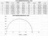
所述计算模块用于接收轴向位移变化量和角度变化值数据后进行计算,得到各测点实时坐标值,并根据各测点实时坐标值以及各测点原始位置坐标值,生成各测点原始及实时坐标对比图。The calculation module is used for calculating after receiving the data of the axial displacement change and the angle change value, obtaining the real-time coordinate value of each measuring point, and generating each measuring point according to the real-time coordinate value of each measuring point and the original position coordinate value of each measuring point. Comparison of raw and real-time coordinates.
可选地,在上述监测系统中,所述分析模块还包括阈值报警模块;Optionally, in the above monitoring system, the analysis module further includes a threshold alarm module;
在轴向位移变化量超过预设位移变化量时,所述阈值报警模块发起报警响应;和/或,When the axial displacement change exceeds the preset displacement change, the threshold alarm module initiates an alarm response; and/or,
在角度变化值超过预设角度变化值时,所述阈值报警模块发起报警响应。When the angle change value exceeds the preset angle change value, the threshold alarm module initiates an alarm response.
本发明提供的变形监测装置在使用时,将套管固定部和滑动体固定部固定在待测位置的固定点,通过滑动体在套管内滑动,同时拉动拉线式位移传感器的牵引件,即可测出待测位置的轴向位移变化量;再通过设置在套管外壁上的倾角传感器即可测出待测位置轴线方向相对水平面的角度变化值。When the deformation monitoring device provided by the present invention is in use, the fixing part of the casing and the fixing part of the sliding body are fixed at the fixed point of the position to be measured, and the sliding body slides in the casing while pulling the traction member of the wire-pulling displacement sensor. The axial displacement change of the position to be measured is measured; then the angle change value of the axial direction of the position to be measured relative to the horizontal plane can be measured through the inclination sensor arranged on the outer wall of the casing.
本发明通过拉线式位移传感器和倾角传感器,即可测量出待测位置的轴向位移变化量和角度变化值,与现有技术中,通过全站仪或监测车测量高程变化量和水平距离变化量相比,投入较低的成本,并实现了对整个隧道断面完整地监测。The invention can measure the axial displacement change and the angle change of the position to be measured through the pull-wire displacement sensor and the inclination sensor, which is different from that in the prior art, which is measured by a total station or a monitoring vehicle to measure the change in elevation and horizontal distance. Compared with the volume, the investment is lower, and the complete monitoring of the entire tunnel section is realized.
附图说明Description of drawings
为了更清楚地说明本发明实施例或现有技术中的技术方案,下面将对实施例或现有技术描述中所需要使用的附图作简单地介绍,显而易见地,下面描述中的附图仅仅是本发明的一些实施例,对于本领域普通技术人员来讲,在不付出创造性劳动的前提下,还可以根据这些附图获得其他的附图。In order to explain the embodiments of the present invention or the technical solutions in the prior art more clearly, the following briefly introduces the accompanying drawings that need to be used in the description of the embodiments or the prior art. Obviously, the accompanying drawings in the following description are only These are some embodiments of the present invention. For those of ordinary skill in the art, other drawings can also be obtained according to these drawings without creative efforts.
图1为本发明实施例提供的变形监测装置的主视图;1 is a front view of a deformation monitoring device provided by an embodiment of the present invention;
图2为本发明实施例提供的变形监测装置的俯视图;2 is a top view of a deformation monitoring device provided by an embodiment of the present invention;
图3为图1中滑动体结构示意图;FIG. 3 is a schematic structural diagram of the sliding body in FIG. 1;
图4为图1中套管结构示意图;Fig. 4 is a schematic diagram of the casing structure in Fig. 1;
图5为本发明实施例提供的固定螺栓的结构示意图;5 is a schematic structural diagram of a fixing bolt provided by an embodiment of the present invention;
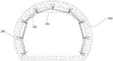
图6为本发明实施例提供的变形监测装置布置点位图;FIG. 6 is an arrangement point map of a deformation monitoring device provided by an embodiment of the present invention;
图7为本发明实施例提供的各测点原始位置及实时位置坐标图。FIG. 7 is a coordinate diagram of the original position and real-time position of each measuring point provided by an embodiment of the present invention.
其中,100为变形监测装置,110为滑动体,111为滑动体固定部,112为固定杆,113为限位凸起,114为滑动体壁,120为套管,121为倾角传感器,122为拉线式位移传感器,123为基座,124为牵引件,125为第一限位件,126为第二限位件,127为套管固定部,128为挂环,200为固定件,201为固定端,202为预埋端,300为隧道壁结构,301为连接线。100 is a deformation monitoring device, 110 is a sliding body, 111 is a sliding body fixing part, 112 is a fixing rod, 113 is a limit protrusion, 114 is a sliding body wall, 120 is a sleeve, 121 is an inclination sensor, and 122 is a Pull-wire displacement sensor, 123 is the base, 124 is the traction member, 125 is the first limiter, 126 is the second limiter, 127 is the sleeve fixing part, 128 is the hanging ring, 200 is the fixing piece, 201 is the The fixed end, 202 is the embedded end, 300 is the tunnel wall structure, and 301 is the connecting line.
具体实施方式Detailed ways
本发明的核心在于提供一种变形监测装置,以在较低投入成本的情况下,能够精确完整地监测到隧道断面的变形。The core of the present invention is to provide a deformation monitoring device, which can accurately and completely monitor the deformation of the tunnel section under the condition of low investment cost.
本发明的另一核心在于提供一种具有上述变形监测装置的监测系统。Another core of the present invention is to provide a monitoring system having the above deformation monitoring device.
以下,参照附图对实施例进行说明。此外,下面所示的实施例不对权利要求所记载的发明内容起任何限定作用。另外,下面实施例所表示的构成的全部内容不限于作为权利要求所记载的发明的解决方案所必需的。Hereinafter, the embodiment will be described with reference to the drawings. In addition, the embodiments shown below do not have any limiting effect on the content of the invention described in the claims. In addition, the whole content of the structure shown in the following embodiment is not limited to what is necessary for the solution of the invention described in the claim.
如图1和图2所示,本发明实施例公开了一种变形监测装置,包括套管120、滑动体110、拉线式位移传感器122和倾角传感器121。As shown in FIGS. 1 and 2 , an embodiment of the present invention discloses a deformation monitoring device, which includes a
其中,套管120设置有一端贯通的空腔,需要说明的是,空腔深度需要本领域相关技术人员根据变形监测装置100量程确定,在套管120背离开口的一端固定连接有套管固定部127,用于固定在待测位置的固定点。当然,本领域技术人员也可根据需求将套管固定部127设置在套管120的其他位置,不是只能设置在套管120的端部。The
滑动体110内设有空腔,且滑动体110嵌套于套管120的空腔内,并且可以与套管120滑动配合,为了方便理解,将伸入到套管120的空腔内的一端称为第一端,外伸于套管120的一端称为第二端,滑动体110的第二端固定有滑动体固定部111,用于固定在待监测位置的固定点。The sliding
在一具体实施例中,为了方便套管固定部127和滑动体固定部111与待监测位置的固定点的固定,套管固定部127和滑动体固定部111可以为环状固定部,环状固定部穿设于待监测位置的固定点,套管固定部127和滑动体固定部111也可以为挂钩状固定部,挂钩状固定部勾住待测位置的固定点,为了更加稳固连接在待测位置的固定点,本发明优选的一种方案,即选用环状固定部穿设于固定点,需要说明的是,只要采用本实施例的固定部,均属于本申请的保护范围。In a specific embodiment, in order to facilitate the fixing of the
拉线式位移传感器122可通过基座123固定安装在套管120的空腔内,也可直接安装在套管120的空腔内,且拉线式位移传感器122具有牵引件124,牵引件124由拉线式位移传感器122伸出,并连接在滑动体110上。当滑动体110在套管120的空腔内的滑动时,同时拉动牵引件124,从而测量出滑动体110沿套管120的轴向位移变化量。The pull-
倾角传感器121固定安装在套管120外壁上,用于测定套管120的轴线方向相对水平面的角度变化值。The
在一具体实施例中,倾角传感器121可以为单轴倾角传感器,即只测量一个方向的水平面的角度变化值,倾角传感器121也可以为双轴倾角传感器,即可以测量两个方向的水平面的角度变化值,需要说明的是,一个方向指的是只有俯仰方向;两个方向指的是既有俯仰方向又有横滚方向,具体选择倾角传感器的种类需要本领域相关技术人员根据实际情况确定。In a specific embodiment, the
本发明提供的变形监测装置,将套管固定部127和滑动体固定部111固定在待测位置的固定点,通过滑动体110在套管120内滑动,同时拉动拉线式位移传感器122的牵引件124,即可测出待测位置的轴向位移变化量;再通过设置在套管120外壁上的倾角传感器121即可测出待测位置轴线方向相对水平面的角度变化值。In the deformation monitoring device provided by the present invention, the
本发明通过拉线式位移传感器122和倾角传感器121,即可测量出待测位置的轴向位移变化量和角度变化值,与现有技术中,通过全站仪或监测车测量高程变化量和水平距离变化量相比,投入较低的成本,并实现了对整个隧道断面完整地监测。The present invention can measure the axial displacement change amount and the angle change value of the position to be measured through the pull-
进一步地,如图4所示,套管120的空腔内分别设置有第一限位件125和第二限位件126,滑动体110的第一端设置有凸起113,凸起113被限制在第一限位件125和第二限位件126之间活动。Further, as shown in FIG. 4 , a first limiting
在一具体实施例中,第一限位件125和第二限位件126为固定在套管120内壁上的环状凸起,当滑动体110位移较大时,由于在滑动体110的凸起113两端设置有环状凸起(即第一限位件125和第二限位件126),阻挡了滑动体110的活动,防止变形监测装置100在使用时,因滑动体110位移过大,超出变形监测装置100的量程,导致变形监测装置100损坏。In a specific embodiment, the first limiting
在另一具体实施例中,第一限位件125和第二限位件126还为沿套管120内壁均匀分布的若干个凸块,其与滑动体110的凸起113配合过程类似于上一具体实施例,在此不再赘述。In another specific embodiment, the first limiting
进一步地,第一限位件125和第二限位件126均设置于套管120的内壁上,在一具体实施例中,为了防止滑动体110的位移超过第二限位件126而破坏拉线式位移传感器122,第二限位件126外凸于套管120的内壁的长度大于第一限位件125外凸于套管120的内壁的长度。Further, the first limiting
进一步地,第一限位件125朝向套管120轴线的一端与滑动体壁114抵接,并且当滑动体110在套管120的空腔内活动时,第一限位件125朝向套管120轴线的一端与滑动体壁114滑动配合。Further, one end of the first limiting
进一步地,如图1和图3所示,为了方便牵引件124连接在滑动体110上,滑动体110的第一端的内腔里设置有与牵引件124配合连接的固定杆112,需要说明的是,固定杆112的具体位置需要本领域相关技术人员根据拉线式位移传感器122的量程确定。本实施例中,通过在滑动体110上设置固定杆112,可方便与牵引件124的连接,与直接将牵引件124固定在滑动体110上相比,通过设置固定杆112,为牵引件124提供了附着基础,可方便、快捷的完成牵引件124与滑动体110的连接。Further, as shown in FIG. 1 and FIG. 3 , in order to facilitate the connection of the
为了方便与滑动体110上设置的固定杆112配合,在牵引件124远离拉线式位移传感器122的一端设置有挂环128,挂环128挂设在固定杆112上。本实施例通过在牵引件124上设置挂环128,只需要将挂环128直接挂在固定杆112上,即可完成牵引件124与滑动体110的连接,与上一实施例相比,安装速度更加快捷。In order to facilitate cooperation with the fixing
由于隧道在投入使用后,车辆经过时,会产生振动,使得挂环128在滑动体110移动,如果位移量较大,可能存在挂环128由固定杆112上脱落的情况。基于此,本发明一具体实施例,在固定杆112端部设置有堵头,堵头可通过过盈的方式固定在固定杆112上,也可通过螺纹固定的方式固定。在变形监测装置受外力或振动影响,而使得挂环128沿固定杆112产生位移时,通过设置堵头,可限制挂环128沿固定杆112向外移动而脱离。After the tunnel is put into use, the vehicle will vibrate when passing through, causing the hanging
进一步地,套管120的空腔内还设置有与滑动体110滑动配合的环形导轨,环形导轨为多个,多个环形导轨分布在第一限位件125朝向套管120开口方向的一侧,多个环形导轨用于限定滑动体110在沿套管120滑动时发生的横向位移,与上一实施例相比,设置多个环形导轨可减小外力或振动对滑动体110的影响,使得变形监测装置100测量更加稳定。Further, the cavity of the
如图5和图6所示,本发明实施例还公开了一种监测系统,包括固定件200、变形监测装置100和分析模块。As shown in FIG. 5 and FIG. 6 , an embodiment of the present invention further discloses a monitoring system including a fixing
其中,固定件200,设置有多个,且多个固定件200的预埋端202依次预埋在隧道壁结构300中,多个固定件200可在隧道壁结构300浇筑前预埋,也可在隧道壁结构300浇筑后埋入,相邻两个固定件200间的距离可由本领域相关技术人员根据变形监测装置100的原始长度而定,需要说明的是,固定件200的位置即为上述实施例中提到的待测位置(即测点)。Among them, a plurality of fixing
如图5所示,固定件200可包括固定端201和预埋端202,其中预埋端202可包括预埋板和设置于预埋板一侧的多个折弯形成的挂钩,预埋板和挂钩均需要预埋在隧道壁结构300中,以增加固定件200与隧道壁结构300的固定强度,防止外力作用下脱落。固定端201可以为固定于预埋板另一侧的固定螺杆,在需要安装变形监测装置100时,可通过滑动体固定部111和套管固定部127挂接在相邻两个固定端201上,然后用螺母旋紧即可实现变形监测装置100的安装。As shown in FIG. 5 , the fixing
变形监测装置100为如上述实施例公开的变形监测装置100,因此兼具上述变形监测装置100的所有技术效果,变形监测装置100通过套管固定部127和滑动体固定部111依次连接在相邻两个固定件200上,通过拉线式位移传感器122测量相邻两个固定件200间沿变形监测装置100的轴向位移变化量;通过倾角传感器121测量出沿变形监测装置100轴线方向相对水平面的角度变化值,通过连接线301传递给分析模块。The
分析模块,接收到拉线式位移传感器122测量的轴向位移变化量和倾角传感器121测量的角度变化值,并进行分析计算得到固定件200位置的实时坐标值。The analysis module receives the axial displacement change measured by the pull-
进一步地,如图7所示,分析模块设置有传输模块和计算模块,传输模块将变形监测装置100监测得到的轴向位移变化量和角度变化值数据传输给计算模块;计算模块接收到传输模块传输过来的轴向位移变化量和角度变化值数据后进行计算,得到各测点实时坐标值,并根据各测点实时坐标值以及各测点原始位置坐标值(各测点原始位置坐标值在确定各测点位置后,可手动输入),生成各测点原始及实时坐标对比图。Further, as shown in FIG. 7 , the analysis module is provided with a transmission module and a calculation module, and the transmission module transmits the axial displacement change amount and angle change value data monitored by the
进一步地,为了防止位移过大而损坏变形监测装置100,分析模块还设置了阈值报警模块。当轴向位移变化量过大并超过了预设位移变化量时,阈值报警模块发起报警响应;和/或,当角度变化值过大并超过了预设角度变化值时,阈值报警模块发起报警响应。与未增加阈值报警模块相比,可提醒相关技术人员隧道壁结构300的变形量超出了变形安全范围,需要及时维护,避免造成更大的事故。需要说明的是,预设位移变化量和预设角度变化值为本领域相关技术人员根据实际工程情况确定。Further, in order to prevent the
本发明的说明书和权利要求书及上述附图中的术语“第一”和“第二”等是用于区别不同的对象,而不是用于描述特定的顺序。此外术语“包括”和“具有”以及他们任何变形,意图在于覆盖不排他的包含。例如包含了一系列步骤或单元的过程、方法、系统、产品或设备没有设定于已列出的步骤或单元,而是可包括没有列出的步骤或单元。The terms "first" and "second" in the description and claims of the present invention and the above drawings are used to distinguish different objects, rather than to describe a specific order. Furthermore, the terms "comprising" and "having" and any variations thereof are intended to cover non-exclusive inclusion. For example, a process, method, system, product, or device that includes a series of steps or elements is not provided with the listed steps or elements, but may include unlisted steps or elements.
对所公开的实施例的上述说明,使本领域专业技术人员能够实现或使用本发明。对这些实施例的多种修改对本领域的专业技术人员来说将是显而易见的,本文中所定义的一般原理可以在不脱离本发明的精神或范围的情况下,在其它实施例中实现。因此,本发明将不会被限制于本文所示的这些实施例,而是要符合与本文所公开的原理和新颖特点相一致的最宽的范围。The above description of the disclosed embodiments enables any person skilled in the art to make or use the present invention. Various modifications to these embodiments will be readily apparent to those skilled in the art, and the generic principles defined herein may be implemented in other embodiments without departing from the spirit or scope of the invention. Thus, the present invention is not intended to be limited to the embodiments shown herein, but is to be accorded the widest scope consistent with the principles and novel features disclosed herein.
Claims (11)
Priority Applications (1)
| Application Number | Priority Date | Filing Date | Title |
|---|---|---|---|
| CN202210695768.XACN115127509A (en) | 2022-06-20 | 2022-06-20 | Deformation monitoring device and monitoring system |
Applications Claiming Priority (1)
| Application Number | Priority Date | Filing Date | Title |
|---|---|---|---|
| CN202210695768.XACN115127509A (en) | 2022-06-20 | 2022-06-20 | Deformation monitoring device and monitoring system |
Publications (1)
| Publication Number | Publication Date |
|---|---|
| CN115127509Atrue CN115127509A (en) | 2022-09-30 |
Family
ID=83378588
Family Applications (1)
| Application Number | Title | Priority Date | Filing Date |
|---|---|---|---|
| CN202210695768.XAPendingCN115127509A (en) | 2022-06-20 | 2022-06-20 | Deformation monitoring device and monitoring system |
Country Status (1)
| Country | Link |
|---|---|
| CN (1) | CN115127509A (en) |
Citations (9)
| Publication number | Priority date | Publication date | Assignee | Title |
|---|---|---|---|---|
| KR200305156Y1 (en)* | 2002-10-25 | 2003-02-25 | 주식회사 동우지오시스템 | 2 dimension tunnel inner wall mutation measurement sensor organizations |
| KR20050072213A (en)* | 2004-01-06 | 2005-07-11 | 정광우 | Unit retrocession displacement measurement system and the measuring method of tunnel |
| CN101769899A (en)* | 2009-10-27 | 2010-07-07 | 中国飞机强度研究所 | Track tracing device |
| CN103791805A (en)* | 2014-01-15 | 2014-05-14 | 重庆市高新工程勘察设计院有限公司 | Landslide deep displacement monitoring system |
| CN104807431A (en)* | 2015-04-25 | 2015-07-29 | 东北大学 | Underground roadway convergence and deformation continuous monitoring device |
| CN204530796U (en)* | 2015-01-28 | 2015-08-05 | 北京城建勘测设计研究院有限责任公司 | A kind of system for the monitoring of base pit engineering fender post Horizontal Displacement |
| CN105136115A (en)* | 2015-10-08 | 2015-12-09 | 北京中力智研物联科技有限公司 | Method and device for automatic measurement of tunnel section deformation |
| JP2020041994A (en)* | 2018-09-13 | 2020-03-19 | 株式会社大林組 | Underground displacement gauge and underground displacement calculation method |
| CN212158519U (en)* | 2020-06-28 | 2020-12-15 | 四川航天电液控制有限公司 | External stay wire displacement sensor |
- 2022
- 2022-06-20CNCN202210695768.XApatent/CN115127509A/enactivePending
Patent Citations (9)
| Publication number | Priority date | Publication date | Assignee | Title |
|---|---|---|---|---|
| KR200305156Y1 (en)* | 2002-10-25 | 2003-02-25 | 주식회사 동우지오시스템 | 2 dimension tunnel inner wall mutation measurement sensor organizations |
| KR20050072213A (en)* | 2004-01-06 | 2005-07-11 | 정광우 | Unit retrocession displacement measurement system and the measuring method of tunnel |
| CN101769899A (en)* | 2009-10-27 | 2010-07-07 | 中国飞机强度研究所 | Track tracing device |
| CN103791805A (en)* | 2014-01-15 | 2014-05-14 | 重庆市高新工程勘察设计院有限公司 | Landslide deep displacement monitoring system |
| CN204530796U (en)* | 2015-01-28 | 2015-08-05 | 北京城建勘测设计研究院有限责任公司 | A kind of system for the monitoring of base pit engineering fender post Horizontal Displacement |
| CN104807431A (en)* | 2015-04-25 | 2015-07-29 | 东北大学 | Underground roadway convergence and deformation continuous monitoring device |
| CN105136115A (en)* | 2015-10-08 | 2015-12-09 | 北京中力智研物联科技有限公司 | Method and device for automatic measurement of tunnel section deformation |
| JP2020041994A (en)* | 2018-09-13 | 2020-03-19 | 株式会社大林組 | Underground displacement gauge and underground displacement calculation method |
| CN212158519U (en)* | 2020-06-28 | 2020-12-15 | 四川航天电液控制有限公司 | External stay wire displacement sensor |
Similar Documents
| Publication | Publication Date | Title |
|---|---|---|
| CN107478370B (en) | Device and method for monitoring displacement and strain stress of whole roadway | |
| US10472793B2 (en) | Method of monitoring subsurface concrete structures | |
| CN108225262B (en) | Method for monitoring settlement of tunnel section based on submillimeter displacement sensor | |
| CN110243335A (en) | A kind of constructing tunnel wall rock loosening ring deformation auto-monitoring prior-warning device and method | |
| AU2017204543A1 (en) | System for dynamically monitoring roadway roof separation based on fibre grating and pre-warning method | |
| CN110453970A (en) | A tower system with internal suspension and internal guyed wires for real-time monitoring of tension and inclination | |
| CN110359961B (en) | Disaster early warning anchor rod based on multi-information perception and disaster early warning method | |
| CN104515791A (en) | Concrete pumping capability monitoring method and device | |
| CN104264589A (en) | Real-time monitoring method for hanging basket states | |
| CN108168513A (en) | A kind of hydraulic support height measuring device and method | |
| CN108680115B (en) | Device for monitoring bidirectional displacement deformation of pipe gallery | |
| CN115127509A (en) | Deformation monitoring device and monitoring system | |
| CN208183704U (en) | The safety pre-warning system in tunnel portal slope construction stage | |
| CN207335700U (en) | A kind of verticality measuring tool | |
| CN108716891A (en) | A kind of underworkings surrouding rock deformation quickly accurately monitors system and its monitoring method | |
| CN208125122U (en) | A kind of hydraulic support height measuring device and system | |
| CN206709816U (en) | High-supported formwork deformation monitoring device in Structural Engineering construction | |
| CN111827242A (en) | A soil slope stability monitoring and early warning device | |
| CN210570632U (en) | Iron tower stability detection alarm device | |
| CN209130452U (en) | Suspension device for laser scanning equipment | |
| CN211012902U (en) | Crack dislocation displacement measurement system | |
| CN115326130B (en) | Deformation measurement early warning system and method for deep buried tunnel crossing active fault | |
| CN210154573U (en) | Highway tunnel earth's surface subsides automatic monitoring early warning device | |
| CN113378269B (en) | Tunnel settlement deformation prediction method | |
| CN216410142U (en) | Road and bridge roughness check out test set |
Legal Events
| Date | Code | Title | Description |
|---|---|---|---|
| PB01 | Publication | ||
| PB01 | Publication | ||
| SE01 | Entry into force of request for substantive examination | ||
| SE01 | Entry into force of request for substantive examination |