CN115126770A - A rotating shaft mechanism and terminal equipment - Google Patents
A rotating shaft mechanism and terminal equipmentDownload PDFInfo
- Publication number
- CN115126770A CN115126770ACN202110312420.3ACN202110312420ACN115126770ACN 115126770 ACN115126770 ACN 115126770ACN 202110312420 ACN202110312420 ACN 202110312420ACN 115126770 ACN115126770 ACN 115126770A
- Authority
- CN
- China
- Prior art keywords
- rotating
- assembly
- sliding
- damping
- spindle
- Prior art date
- Legal status (The legal status is an assumption and is not a legal conclusion. Google has not performed a legal analysis and makes no representation as to the accuracy of the status listed.)
- Pending
Links
Images


Classifications
- H—ELECTRICITY
- H04—ELECTRIC COMMUNICATION TECHNIQUE
- H04M—TELEPHONIC COMMUNICATION
- H04M1/00—Substation equipment, e.g. for use by subscribers
- H04M1/02—Constructional features of telephone sets
- H04M1/0202—Portable telephone sets, e.g. cordless phones, mobile phones or bar type handsets
- H04M1/0206—Portable telephones comprising a plurality of mechanically joined movable body parts, e.g. hinged housings
- H04M1/0208—Portable telephones comprising a plurality of mechanically joined movable body parts, e.g. hinged housings characterized by the relative motions of the body parts
- H04M1/0214—Foldable telephones, i.e. with body parts pivoting to an open position around an axis parallel to the plane they define in closed position
- H04M1/0216—Foldable in one direction, i.e. using a one degree of freedom hinge
- H04M1/022—The hinge comprising two parallel pivoting axes
- F—MECHANICAL ENGINEERING; LIGHTING; HEATING; WEAPONS; BLASTING
- F16—ENGINEERING ELEMENTS AND UNITS; GENERAL MEASURES FOR PRODUCING AND MAINTAINING EFFECTIVE FUNCTIONING OF MACHINES OR INSTALLATIONS; THERMAL INSULATION IN GENERAL
- F16C—SHAFTS; FLEXIBLE SHAFTS; ELEMENTS OR CRANKSHAFT MECHANISMS; ROTARY BODIES OTHER THAN GEARING ELEMENTS; BEARINGS
- F16C11/00—Pivots; Pivotal connections
- F16C11/04—Pivotal connections
- F16C11/12—Pivotal connections incorporating flexible connections, e.g. leaf springs
- F—MECHANICAL ENGINEERING; LIGHTING; HEATING; WEAPONS; BLASTING
- F16—ENGINEERING ELEMENTS AND UNITS; GENERAL MEASURES FOR PRODUCING AND MAINTAINING EFFECTIVE FUNCTIONING OF MACHINES OR INSTALLATIONS; THERMAL INSULATION IN GENERAL
- F16C—SHAFTS; FLEXIBLE SHAFTS; ELEMENTS OR CRANKSHAFT MECHANISMS; ROTARY BODIES OTHER THAN GEARING ELEMENTS; BEARINGS
- F16C11/00—Pivots; Pivotal connections
- F16C11/04—Pivotal connections
- G—PHYSICS
- G06—COMPUTING OR CALCULATING; COUNTING
- G06F—ELECTRIC DIGITAL DATA PROCESSING
- G06F1/00—Details not covered by groups G06F3/00 - G06F13/00 and G06F21/00
- G06F1/16—Constructional details or arrangements
- G06F1/1613—Constructional details or arrangements for portable computers
- G06F1/1615—Constructional details or arrangements for portable computers with several enclosures having relative motions, each enclosure supporting at least one I/O or computing function
- G06F1/1616—Constructional details or arrangements for portable computers with several enclosures having relative motions, each enclosure supporting at least one I/O or computing function with folding flat displays, e.g. laptop computers or notebooks having a clamshell configuration, with body parts pivoting to an open position around an axis parallel to the plane they define in closed position
- G—PHYSICS
- G06—COMPUTING OR CALCULATING; COUNTING
- G06F—ELECTRIC DIGITAL DATA PROCESSING
- G06F1/00—Details not covered by groups G06F3/00 - G06F13/00 and G06F21/00
- G06F1/16—Constructional details or arrangements
- G06F1/1613—Constructional details or arrangements for portable computers
- G06F1/1633—Constructional details or arrangements of portable computers not specific to the type of enclosures covered by groups G06F1/1615 - G06F1/1626
- G06F1/1637—Details related to the display arrangement, including those related to the mounting of the display in the housing
- G06F1/1641—Details related to the display arrangement, including those related to the mounting of the display in the housing the display being formed by a plurality of foldable display components
- G—PHYSICS
- G06—COMPUTING OR CALCULATING; COUNTING
- G06F—ELECTRIC DIGITAL DATA PROCESSING
- G06F1/00—Details not covered by groups G06F3/00 - G06F13/00 and G06F21/00
- G06F1/16—Constructional details or arrangements
- G06F1/1613—Constructional details or arrangements for portable computers
- G06F1/1633—Constructional details or arrangements of portable computers not specific to the type of enclosures covered by groups G06F1/1615 - G06F1/1626
- G06F1/1637—Details related to the display arrangement, including those related to the mounting of the display in the housing
- G06F1/1652—Details related to the display arrangement, including those related to the mounting of the display in the housing the display being flexible, e.g. mimicking a sheet of paper, or rollable
- G—PHYSICS
- G06—COMPUTING OR CALCULATING; COUNTING
- G06F—ELECTRIC DIGITAL DATA PROCESSING
- G06F1/00—Details not covered by groups G06F3/00 - G06F13/00 and G06F21/00
- G06F1/16—Constructional details or arrangements
- G06F1/1613—Constructional details or arrangements for portable computers
- G06F1/1633—Constructional details or arrangements of portable computers not specific to the type of enclosures covered by groups G06F1/1615 - G06F1/1626
- G06F1/1675—Miscellaneous details related to the relative movement between the different enclosures or enclosure parts
- G06F1/1681—Details related solely to hinges
- G—PHYSICS
- G09—EDUCATION; CRYPTOGRAPHY; DISPLAY; ADVERTISING; SEALS
- G09F—DISPLAYING; ADVERTISING; SIGNS; LABELS OR NAME-PLATES; SEALS
- G09F9/00—Indicating arrangements for variable information in which the information is built-up on a support by selection or combination of individual elements
- G09F9/30—Indicating arrangements for variable information in which the information is built-up on a support by selection or combination of individual elements in which the desired character or characters are formed by combining individual elements
- G09F9/301—Indicating arrangements for variable information in which the information is built-up on a support by selection or combination of individual elements in which the desired character or characters are formed by combining individual elements flexible foldable or roll-able electronic displays, e.g. thin LCD, OLED
- H—ELECTRICITY
- H05—ELECTRIC TECHNIQUES NOT OTHERWISE PROVIDED FOR
- H05K—PRINTED CIRCUITS; CASINGS OR CONSTRUCTIONAL DETAILS OF ELECTRIC APPARATUS; MANUFACTURE OF ASSEMBLAGES OF ELECTRICAL COMPONENTS
- H05K5/00—Casings, cabinets or drawers for electric apparatus
- H05K5/02—Details
- H05K5/0217—Mechanical details of casings
- H05K5/0226—Hinges
- E—FIXED CONSTRUCTIONS
- E05—LOCKS; KEYS; WINDOW OR DOOR FITTINGS; SAFES
- E05D—HINGES OR SUSPENSION DEVICES FOR DOORS, WINDOWS OR WINGS
- E05D3/00—Hinges with pins
- E05D3/06—Hinges with pins with two or more pins
- E05D3/12—Hinges with pins with two or more pins with two parallel pins and one arm
- E—FIXED CONSTRUCTIONS
- E05—LOCKS; KEYS; WINDOW OR DOOR FITTINGS; SAFES
- E05Y—INDEXING SCHEME ASSOCIATED WITH SUBCLASSES E05D AND E05F, RELATING TO CONSTRUCTION ELEMENTS, ELECTRIC CONTROL, POWER SUPPLY, POWER SIGNAL OR TRANSMISSION, USER INTERFACES, MOUNTING OR COUPLING, DETAILS, ACCESSORIES, AUXILIARY OPERATIONS NOT OTHERWISE PROVIDED FOR, APPLICATION THEREOF
- E05Y2999/00—Subject-matter not otherwise provided for in this subclass
- H—ELECTRICITY
- H04—ELECTRIC COMMUNICATION TECHNIQUE
- H04M—TELEPHONIC COMMUNICATION
- H04M1/00—Substation equipment, e.g. for use by subscribers
- H04M1/02—Constructional features of telephone sets
- H04M1/0202—Portable telephone sets, e.g. cordless phones, mobile phones or bar type handsets
- H04M1/026—Details of the structure or mounting of specific components
- H04M1/0266—Details of the structure or mounting of specific components for a display module assembly
- H04M1/0268—Details of the structure or mounting of specific components for a display module assembly including a flexible display panel
Landscapes
- Engineering & Computer Science (AREA)
- Theoretical Computer Science (AREA)
- Computer Hardware Design (AREA)
- General Engineering & Computer Science (AREA)
- Physics & Mathematics (AREA)
- General Physics & Mathematics (AREA)
- Human Computer Interaction (AREA)
- Mechanical Engineering (AREA)
- Microelectronics & Electronic Packaging (AREA)
- Mathematical Physics (AREA)
- Signal Processing (AREA)
- Pivots And Pivotal Connections (AREA)
- Telephone Set Structure (AREA)
Abstract
Translated fromChinese
Description
Translated fromChinese技术领域technical field
本申请涉及到终端设备技术领域,尤其涉及到一种转轴机构及终端设备。The present application relates to the technical field of terminal equipment, and in particular, to a rotating shaft mechanism and terminal equipment.
背景技术Background technique
随着柔性折叠屏技术日趋成熟,促使终端设备的显示方式发生了非常大的变化,可折叠终端产品必将是未来终端产品发展的一大趋势。可折叠终端产品(如折叠手机、折叠平板、折叠电脑等电子设备)需要满足较高的可靠性,较好的操作体验,才容易被消费者所接受。With the maturity of flexible folding screen technology, the display mode of terminal equipment has undergone great changes, and foldable terminal products will definitely be a major trend in the development of terminal products in the future. Foldable terminal products (such as foldable mobile phones, foldable tablets, foldable computers and other electronic devices) need to meet higher reliability and better operating experience before they are easily accepted by consumers.
以可折叠手机为例,其柔性屏可以根据不同的使用场景灵活变化以切换使用模式,这也是当下手机厂商的研发方向。但是,柔性屏只是可折叠手机的结构中的一部分,要实现整个终端产品的可折叠还需要转轴机构的配合。转轴机构除了可用于实现可折叠手机的折叠状态的改变,还可以为整个可折叠手机在不同的折叠状态下提供足够的阻尼力,以使可折叠手机在进行折叠状态切换的过程中具有可靠的支撑力。Taking a foldable mobile phone as an example, its flexible screen can be flexibly changed according to different usage scenarios to switch usage modes, which is also the current research and development direction of mobile phone manufacturers. However, the flexible screen is only a part of the structure of the foldable mobile phone, and the cooperation of the hinge mechanism is also required to realize the foldability of the entire terminal product. In addition to realizing the change of the folded state of the foldable mobile phone, the hinge mechanism can also provide sufficient damping force for the entire foldable mobile phone in different folding states, so that the foldable mobile phone has reliable performance during the process of switching the folding state. support.
可折叠终端产品具有可靠的支撑力,可有效的降低柔性屏损坏的风险。因此,转轴机构能够为整个终端产品提供的有效的阻尼力的大小和稳定性,已成为目前本领域的技术人员重点研究的课题。The foldable terminal product has reliable support, which can effectively reduce the risk of damage to the flexible screen. Therefore, the size and stability of the effective damping force that the rotating shaft mechanism can provide for the entire end product has become a key research topic for those skilled in the art at present.
发明内容SUMMARY OF THE INVENTION
本申请提供了一种转轴机构及终端设备,以使转轴机构能够为整个终端设备提供满足要求的阻尼力。The present application provides a rotating shaft mechanism and terminal equipment, so that the rotating shaft mechanism can provide damping force that meets the requirements for the entire terminal equipment.
第一方面,提供了一种转轴机构,该转轴机构可应用于可折叠的终端设备,终端设备包括两个壳体,两个壳体可分别绕转轴机构转动以实现终端设备的闭合以及展开。转轴机构包括主轴组件和阻尼组件,阻尼组件与主轴组件转动连接。在具体设置阻尼组件时,阻尼组件可以包括凸轮件和转动组件,凸轮件固定于主轴组件,凸轮件具有凸轮面。而转动组件包括转动件和滑动件,转动件与主轴组件转动连接,以带动整个转动组件绕主轴组件的转动。另外,滑动件可相对转动件沿朝向或者背离主轴组件的方向滑动,且在滑动件相对转动件转动的过程中,滑动件还与凸轮面弹性抵接,以在主轴组件与阻尼组件之间产生阻尼力。该弹性抵接形成的抵接力可转化为凸轮件和转动组件相对转动的阻力,从而在主轴组件与阻尼组件之间产生阻尼力。另外,通过合理设计滑动件和凸轮面之间的弹性抵接力以及凸轮面的具体形态,可以有效的提高对终端设备的折叠操作体验的舒适度,另外,还可以使阻尼组件的寿命得到保证。In a first aspect, a hinge mechanism is provided. The hinge mechanism can be applied to a foldable terminal device. The terminal device includes two housings that can be rotated around the hinge mechanism to realize closing and unfolding of the terminal device. The rotating shaft mechanism includes a main shaft assembly and a damping assembly, and the damping assembly is rotatably connected with the main shaft assembly. When specifically setting the damping assembly, the damping assembly may include a cam member and a rotating assembly, the cam member is fixed to the main shaft assembly, and the cam member has a cam surface. The rotating assembly includes a rotating member and a sliding member, and the rotating member is rotatably connected with the main shaft assembly to drive the entire rotating assembly to rotate around the main shaft assembly. In addition, the sliding member can slide relative to the rotating member in a direction toward or away from the main shaft assembly, and during the rotation of the sliding member relative to the rotating member, the sliding member also elastically abuts against the cam surface, so as to generate a gap between the main shaft assembly and the damping member. damping force. The abutting force formed by the elastic abutment can be converted into a resistance against the relative rotation of the cam member and the rotating component, thereby generating a damping force between the main shaft component and the damping component. In addition, by reasonably designing the elastic contact force between the slider and the cam surface and the specific shape of the cam surface, the comfort of the folding operation experience of the terminal device can be effectively improved, and the service life of the damping component can also be guaranteed.
转动件作为转动组件绕主轴组件转动的关键结构,在具体设置时,可使转动件包括本体部和连接部。其中,连接部与本体部固定连接,连接部用于与主轴组件转动连接,连接部可以设置为圆弧轴,相适应的主轴组件设置有圆弧槽,圆弧轴与圆弧槽滑动配合以使转动件与主轴组件之间通过虚拟轴实现转动连接。该连接方式可以有利于实现转轴机构的薄型化设计。本体部设置有滑槽,滑动件的至少部分容置于滑槽。这样可使滑动件的至少部分容置于滑槽,并在滑槽内滑动。As a key structure for the rotating component to rotate around the main shaft component, the rotating member can be set to include a main body portion and a connecting portion during specific setting. The connecting part is fixedly connected with the main body part, and the connecting part is used for rotating connection with the main shaft assembly; The rotation connection between the rotating part and the main shaft assembly is realized through a virtual axis. This connection method can be beneficial to realize the thin design of the rotating shaft mechanism. The main body is provided with a chute, and at least part of the sliding piece is accommodated in the chute. This allows at least part of the slider to be accommodated in the chute and slide within the chute.
转动件除了采用上述的设置方式外,在本申请一个可能的实现方式中,转动件还可以包括第一转动臂、第二转动臂和连接臂。其中,第一转动臂和第二转动臂分别与主轴组件转动连接,第一转动臂和第二转动臂的背离主轴组件的端部通过连接臂固定连接。另外,第一转动臂、第二转动臂和连接部的用于围成滑槽的部分可作为转动件的本体部;第一转动臂和第二转动臂的用于与主轴组件转动连接的端部可作为转动件的连接部。In addition to the above-mentioned arrangement of the rotating member, in a possible implementation manner of the present application, the rotating member may further include a first rotating arm, a second rotating arm and a connecting arm. Wherein, the first rotating arm and the second rotating arm are respectively rotatably connected with the main shaft assembly, and the ends of the first rotating arm and the second rotating arm facing away from the main shaft assembly are fixedly connected by the connecting arms. In addition, the parts of the first rotating arm, the second rotating arm and the connecting part used to enclose the chute can be used as the body part of the rotating member; the ends of the first rotating arm and the second rotating arm used for rotating connection with the spindle assembly The part can be used as the connecting part of the rotating part.
在转轴机构中,可包括成对设置的两个阻尼组件,该两个阻尼组件的同步转动,可提高转轴机构的运动稳定性。为了实现两个阻尼组件的同步转动,在本申请一个可能的实现方式中,可使第一转动臂的用于与主轴组件转动连接的端部设置有齿轮结构,第二转动臂的用于与主轴组件转动连接的端部设置有齿轮结构。这样,该成对设置的两个阻尼组件中一个阻尼组件的第一转动臂的齿轮结构,与另一个阻尼组件的对应侧的第一转动臂或第二转动臂的齿轮结构相啮合。相类似的,该成对设置的两个阻尼组件中一个阻尼组件的第二转动臂的齿轮结构,与另一个阻尼组件的对应侧的第二转动臂或第一转动臂的齿轮结构相啮合。从而使两个阻尼组件通过对应侧的转动臂的齿轮结构之间的啮合来实现其同步运动。In the rotating shaft mechanism, two damping assemblies arranged in pairs may be included, and the synchronous rotation of the two damping assemblies can improve the motion stability of the rotating shaft mechanism. In order to realize the synchronous rotation of the two damping assemblies, in a possible implementation manner of the present application, a gear structure may be provided at the end of the first rotating arm that is used for rotational connection with the main shaft assembly, and the end of the second rotating arm is used to connect with the main shaft assembly. A gear structure is provided at the end of the main shaft assembly that is rotatably connected. In this way, the gear structure of the first rotating arm of one damping assembly in the paired damping assembly meshes with the gear structure of the first rotating arm or the second rotating arm on the corresponding side of the other damping assembly. Similarly, the gear structure of the second rotating arm of one damping assembly in the paired damping assemblies meshes with the gear structure of the second rotating arm or the first rotating arm on the corresponding side of the other damping assembly. Therefore, the two damping assemblies can achieve their synchronous movement through the meshing between the gear structures of the rotating arms on the corresponding side.
另外,在主轴组件的长度方向上,相啮合的两个齿轮结构的两侧还各设置有一个挡板,该挡板用于对两个齿轮结构的中心距进行限位,从而可提高该两个齿轮结构之间运动传动的稳定性。In addition, in the length direction of the main shaft assembly, a baffle plate is provided on each side of the two meshing gear structures, and the baffle plates are used to limit the center distance of the two gear structures, so that the two gear structures can be improved The stability of the motion transmission between the gear structures.
在本申请一个可能的实现方式中,在具体设置滑动件时,滑动件可以包括滑块,滑块可在滑槽内沿朝向或者背离主轴组件的方向滑动。为了提高滑块在滑槽内滑动的稳定性,在本申请一个可能的实现方式中,在滑槽的两个相对的槽壁上可分别设置有第一滑动部和第二滑动部,而在滑块上设置有第三滑动部和第四滑动部。其中,第三滑动部与第一滑动部滑动配合,第四滑动部与第二滑动部滑动配合。In a possible implementation manner of the present application, when the sliding member is specifically arranged, the sliding member may include a sliding block, and the sliding block may slide in a direction toward or away from the main shaft assembly in the sliding groove. In order to improve the sliding stability of the slider in the chute, in a possible implementation manner of the present application, a first sliding part and a second sliding part may be respectively provided on two opposite groove walls of the The slider is provided with a third sliding part and a fourth sliding part. Wherein, the third sliding part is slidably matched with the first sliding part, and the fourth sliding part is slidably matched with the second sliding part.
另外,在滑槽内还设置有弹性元件,滑块与该弹性元件弹性连接。由于凸轮件可固定于主轴组件,这样,在滑块在相对转动件沿朝向或者背离主轴组件的方向滑动的过程中,弹性元件可将滑块压向凸轮件,从而实现滑块与凸轮件的弹性抵接。In addition, an elastic element is also arranged in the chute, and the sliding block is elastically connected with the elastic element. Since the cam member can be fixed to the main shaft assembly, in the process of sliding the slider relative to the rotating member in the direction toward or away from the main shaft assembly, the elastic element can press the slider towards the cam member, thereby realizing the connection between the slider and the cam member. Elastic abutment.
为了减小滑块沿凸轮面运动的过程中造成的磨损,在本申请一个可能的实现方式中,还可以在滑块上设置滚轮,该滚轮通过滚轮轴与滑块转动连接,滚轮可与凸轮面弹性抵接。从而使滑动件与凸轮之间的摩擦为滚动摩擦。In order to reduce the wear caused by the sliding block moving along the cam surface, in a possible implementation manner of the present application, a roller can also be provided on the sliding block, the roller is rotatably connected with the sliding block through the roller shaft, and the roller can Surface elastic contact. Thus, the friction between the slider and the cam is rolling friction.
在本申请另一个可能的实现方式中,滑块的端部还可以设置有抵接部,该抵接部与凸轮面相抵接。另外,抵接部的表面可以为圆弧面或者球面,其同样可以起到减小滑块与凸轮面之间的磨损的作用。In another possible implementation manner of the present application, the end portion of the slider may further be provided with an abutment portion, and the abutment portion abuts against the cam surface. In addition, the surface of the abutting portion can be a circular arc surface or a spherical surface, which can also play the role of reducing the wear between the slider and the cam surface.
第二方面,还提供了一种转轴机构,该转轴机构包括主轴组件和阻尼组件,阻尼组件与主轴组件转动连接。在具体设置阻尼组件时,阻尼组件可以包括凸轮件和转动组件,凸轮件设置于转动组件,凸轮件具有凸轮面。而转动组件包括转动件和滑动件,转动件与主轴组件转动连接,以带动整个转动组件绕主轴组件的转动。另外,滑动件可相对转动件沿朝向或者背离主轴组件的方向滑动,且在滑动件相对转动件转动的过程中,滑动件还与凸轮面弹性抵接,以在主轴组件与阻尼组件之间产生阻尼力。该弹性抵接形成的抵接力可转化为凸轮件和转动组件相对转动的阻力,从而在主轴组件与阻尼组件之间产生阻尼力。另外,通过合理设计滑动件和凸轮面之间的弹性抵接力以及凸轮面的具体形态,可以有效的提高对终端设备的折叠操作体验的舒适度,另外,还可以使阻尼组件的寿命得到保证。In a second aspect, a rotating shaft mechanism is also provided. The rotating shaft mechanism includes a main shaft assembly and a damping assembly, and the damping assembly is rotatably connected to the main shaft assembly. When the damping assembly is specifically provided, the damping assembly may include a cam member and a rotating assembly, the cam member is disposed on the rotating assembly, and the cam member has a cam surface. The rotating assembly includes a rotating member and a sliding member, and the rotating member is rotatably connected with the main shaft assembly to drive the entire rotating assembly to rotate around the main shaft assembly. In addition, the sliding member can slide relative to the rotating member in a direction toward or away from the main shaft assembly, and during the rotation of the sliding member relative to the rotating member, the sliding member also elastically abuts against the cam surface, so as to generate a gap between the main shaft assembly and the damping member. damping force. The abutting force formed by the elastic abutment can be converted into a resistance against the relative rotation of the cam member and the rotating component, thereby generating a damping force between the main shaft component and the damping component. In addition, by reasonably designing the elastic contact force between the slider and the cam surface and the specific shape of the cam surface, the comfort of the folding operation experience of the terminal device can be effectively improved, and the service life of the damping component can also be guaranteed.
在本申请一个可能的实现方式中,在具体设置转动件时,转动件包括本体部和连接部。其中,连接部与本体部固定连接,连接部用于与主轴组件转动连接,连接部可以设置为圆弧轴,相适应的主轴组件设置有圆弧槽,圆弧轴与圆弧槽滑动配合以使转动件与主轴组件之间通过虚拟轴实现转动连接。该连接方式可以有利于实现转轴机构的薄型化设计。本体部设置有滑槽,滑动件的至少部分容置于滑槽。这样可使滑动件的至少部分容置于滑槽,并在滑槽内滑动。In a possible implementation manner of the present application, when the rotating member is specifically arranged, the rotating member includes a body portion and a connecting portion. The connecting part is fixedly connected with the main body part, and the connecting part is used for rotating connection with the main shaft assembly; The rotation connection between the rotating part and the main shaft assembly is realized through a virtual axis. This connection method can be beneficial to realize the thin design of the rotating shaft mechanism. The main body is provided with a chute, and at least part of the sliding piece is accommodated in the chute. This allows at least part of the slider to be accommodated in the chute and slide within the chute.
在具体设置滑动件时,滑动件可以包括滑块和转动部,转动部与主轴组件转动连接,滑块与转动部转动连接。另外,转动部绕主轴组件转动的轴线,与转动件绕主轴组件转动的轴线相互平行但不重合。从而在转动组件绕主轴组件转动的过程中,使滑块和转动件的运动之间产生相位差,从而实现滑块在滑槽内的沿朝向或者背离主轴组件的方向滑动。When the sliding member is specifically arranged, the sliding member may include a sliding block and a rotating part, the rotating part is rotatably connected with the main shaft assembly, and the sliding block is rotatably connected with the rotating part. In addition, the axis of rotation of the rotating part around the main shaft assembly is parallel to but not coincident with the axis of rotation of the rotating part around the main shaft assembly. Therefore, during the rotation of the rotating assembly around the main shaft assembly, a phase difference is generated between the movement of the sliding block and the rotating member, so that the sliding block can slide in the direction toward or away from the main shaft assembly in the chute.
在转动部上可以设置有齿轮结构,而转轴机构可以包括成对设置的两个阻尼组件,两个阻尼组件的转动部的齿轮结构相啮合,从而实现两个阻尼组件的同步转动,以提高转轴机构的运动稳定性。A gear structure may be provided on the rotating part, and the rotating shaft mechanism may include two damping assemblies arranged in pairs, and the gear structures of the rotating parts of the two damping assemblies are meshed, so as to realize the synchronous rotation of the two damping assemblies, so as to improve the rotation speed of the rotating shaft. Movement stability of the mechanism.
另外,在主轴组件的长度方向上,相啮合的两个齿轮结构的两侧还各设置有一个挡板,该挡板用于对两个齿轮结构的中心距进行限位,从而可提高该两个齿轮结构之间运动传动的稳定性。In addition, in the length direction of the main shaft assembly, a baffle plate is provided on each side of the two meshing gear structures, and the baffle plates are used to limit the center distance of the two gear structures, so that the two gear structures can be improved The stability of the motion transmission between the gear structures.
为了将凸轮件设置于转动组件,在转动件的本体部上还设置有安装槽。安装槽为两个,沿主轴组件的长度方向上,两个安装槽分别设置于滑槽的两侧,安装槽通过过孔与滑槽相连通。在将凸轮件安装于安装槽后,凸轮件设置有凸轮面的一端伸入过孔。凸轮件可在安装槽内沿朝向或者背离滑槽的方向运动。In order to set the cam member on the rotating assembly, a mounting groove is also provided on the main body of the rotating member. There are two installation grooves. Along the length direction of the main shaft assembly, the two installation grooves are respectively arranged on both sides of the chute, and the installation grooves are communicated with the chute through through holes. After the cam piece is installed in the installation groove, the end of the cam piece provided with the cam surface extends into the through hole. The cam member can move in the mounting groove in a direction toward or away from the chute.
另外,在安装槽内设置有弹性元件,凸轮件与弹性元件弹性连接,这样弹性元件可将凸轮件压向滑块,以使滑块与凸轮件的凸轮面弹性抵接。In addition, an elastic element is arranged in the installation groove, and the cam element is elastically connected with the elastic element, so that the elastic element can press the cam element to the slider, so that the slider and the cam surface of the cam element are in elastic contact.
在本申请一个可能的实现方式中,还可以使滑块的朝向凸轮件的端部设置有倾斜面。此实现方案中,凸轮件的凸轮面可与倾斜面相抵接,以对滑块施加沿远离主轴组件的推力。可以理解的是,通过对凸轮的凸轮面和滑块的倾斜面的合理设计,可对阻尼组件提供的阻尼力进行调整,从而满足用户对操作手感的要求。In a possible implementation manner of the present application, the end of the slider facing the cam member may also be provided with an inclined surface. In this implementation solution, the cam surface of the cam member can abut with the inclined surface, so as to exert a thrust force on the slider away from the main shaft assembly. It can be understood that the damping force provided by the damping component can be adjusted through reasonable design of the cam surface of the cam and the inclined surface of the slider, so as to meet the user's requirements for the operation feel.
另外,凸轮件还可以设置有凸台,滑块对凸台朝向安装槽的槽口方向的运动进行限位,以将凸轮件限位于安装槽。从而可避免凸轮件从安装槽中脱落,提高转轴机构的结构稳定性。In addition, the cam member may also be provided with a boss, and the slider limits the movement of the boss towards the notch of the installation groove, so as to limit the cam member to the installation groove. Therefore, the cam piece can be prevented from falling off from the installation groove, and the structural stability of the rotating shaft mechanism can be improved.
在本申请一个可能的实现方式中,在具体设置主轴组件时,主轴组件可与包括主内轴和主外轴。其中,主内轴和主外轴相扣合以围成用于容纳转轴机构的其它部件的容纳空间。可以理解的是,上述转动组件的用于与主轴组件转动连接的部分也可容纳于该容纳空间。In a possible implementation manner of the present application, when the main shaft assembly is specifically configured, the main shaft assembly may include a main inner shaft and a main outer shaft. Wherein, the main inner shaft and the main outer shaft are fastened together to enclose an accommodating space for accommodating other components of the rotating shaft mechanism. It can be understood that, the part of the above-mentioned rotating assembly for rotatably connecting with the main shaft assembly can also be accommodated in the accommodating space.
第三方面,提供了一种终端设备,终端设备包括柔性屏、第一壳体、第二壳体以及上述第一方面或第二方面的转轴机构。其中,第一壳体和第二壳体分列在转轴机构两侧,且第一壳体和第二壳体分别与对应侧的阻尼组件连接。柔性屏可连续覆盖于第一壳体、第二壳体以及转轴机构上,且柔性屏与第一壳体和第二壳体固定连接。在本申请技术方案中,通过滑动件与凸轮件的弹性抵接,以在主轴组件与阻尼组件之间产生阻尼力。从而能够为终端设备处于展平状态时提供足够的支撑力。另外,可通对凸轮件的凸轮面的具体形态进行合理设计,来提高转轴机构对终端设备的折叠操作体验的舒适度,并使阻尼组件的寿命得到保证。In a third aspect, a terminal device is provided, where the terminal device includes a flexible screen, a first casing, a second casing, and the rotating shaft mechanism of the first aspect or the second aspect. Wherein, the first casing and the second casing are arranged on both sides of the rotating shaft mechanism, and the first casing and the second casing are respectively connected with the damping components on the corresponding side. The flexible screen can be continuously covered on the first casing, the second casing and the rotating shaft mechanism, and the flexible screen is fixedly connected with the first casing and the second casing. In the technical solution of the present application, a damping force is generated between the main shaft assembly and the damping assembly through elastic contact between the sliding member and the cam member. Thus, sufficient support can be provided for the terminal device when it is in a flattened state. In addition, the specific shape of the cam surface of the cam member can be reasonably designed to improve the comfort of the rotating shaft mechanism for the folding operation experience of the terminal device, and to ensure the service life of the damping component.
附图说明Description of drawings
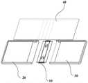
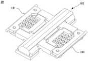
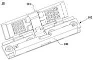
图1为本申请一实施例提供的终端设备的分解结构示意图;FIG. 1 is a schematic diagram of an exploded structure of a terminal device provided by an embodiment of the present application;
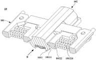
图2为本申请一实施例提供的转轴机构处于展平状态的结构示意图;2 is a schematic structural diagram of a rotating shaft mechanism provided in an embodiment of the application in a flattened state;
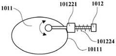
图3为本申请一实施例提供的转轴机构的阻尼组件的结构原理图;3 is a schematic structural diagram of a damping component of a rotating shaft mechanism provided by an embodiment of the application;
图4a为本申请一实施例提供的转轴机构的结构示意图;4a is a schematic structural diagram of a rotating shaft mechanism provided by an embodiment of the application;
图4b为图4a中转轴机构的另一角度下的结构示意图;Figure 4b is a schematic structural diagram of the rotating shaft mechanism in Figure 4a from another angle;
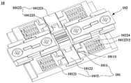
图5为本申请一实施例提供的转轴机构的分解结构示意图;5 is a schematic diagram of an exploded structure of a rotating shaft mechanism provided by an embodiment of the present application;
图6为本申请一实施例提供的转动件的结构示意图;6 is a schematic structural diagram of a rotating member provided by an embodiment of the present application;
图7为本申请一实施例提供的主轴组件的分解结构示意图;7 is a schematic diagram of an exploded structure of a spindle assembly provided by an embodiment of the application;
图8为本申请一实施例提供的主内轴的结构示意图;8 is a schematic structural diagram of a main inner shaft provided by an embodiment of the present application;
图9为图8中的A-A剖面图;Fig. 9 is A-A sectional view in Fig. 8;
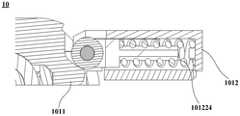
图10为本申请一实施例提供的转轴机构的局部结构示意图;10 is a schematic partial structure diagram of a rotating shaft mechanism provided by an embodiment of the application;
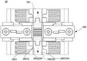
图11a至图11d为本申请一实施例提供的转轴机构处于不同折叠程度的剖面图;11a to 11d are cross-sectional views of the rotating shaft mechanism provided in an embodiment of the application at different degrees of folding;
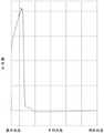
图12为本申请一实施例提供的转轴机构从展平状态到闭合状态过程中操作力示意图;12 is a schematic diagram of the operating force of the rotating shaft mechanism in the process from a flat state to a closed state according to an embodiment of the application;
图13a为本申请另一实施例提供的转轴机构的结构示意图;13a is a schematic structural diagram of a rotating shaft mechanism provided by another embodiment of the present application;
图13b为图13a中转轴机构的另一角度下的结构示意图;Fig. 13b is a schematic structural diagram of the rotating shaft mechanism in Fig. 13a from another angle;
图14为本申请另一实施例提供的转轴机构的分解结构示意图;14 is a schematic diagram of an exploded structure of a rotating shaft mechanism provided by another embodiment of the present application;
图15为本申请另一实施例提供的滑块的结构示意图;15 is a schematic structural diagram of a slider provided by another embodiment of the present application;
图16为本申请另一实施例提供的相啮合的第一转动臂和第二转动臂的连接关系示意图;16 is a schematic diagram of the connection relationship between the meshed first rotating arm and the second rotating arm provided by another embodiment of the application;
图17为本申请另一实施例提供的主内轴的结构示意图;17 is a schematic structural diagram of a main inner shaft provided by another embodiment of the application;
图18为本申请另一实施例提供的转轴机构的局部结构示意图;18 is a schematic partial structure diagram of a rotating shaft mechanism provided by another embodiment of the present application;
图19a至图19c为本申请另一实施例提供的转轴机构处于不同折叠程度的剖面图;19a to 19c are cross-sectional views of the rotating shaft mechanism provided in another embodiment of the application at different degrees of folding;
图20为本申请一实施例提供的转轴机构从展平状态到闭合状态过程中操作力示意图;20 is a schematic diagram of the operating force of the rotating shaft mechanism in the process from a flat state to a closed state according to an embodiment of the application;
图21a为本申请另一实施例提供的转轴机构处于展平状态的结构示意图;FIG. 21a is a schematic structural diagram of a rotating shaft mechanism in a flattened state provided by another embodiment of the present application;
图21b为图21a中转轴机构的另一角度下的结构示意图;Fig. 21b is a schematic structural diagram of the rotating shaft mechanism in Fig. 21a from another angle;
图21c为本申请另一实施例提供的转轴机构处于中间状态的结构示意图;21c is a schematic structural diagram of a rotating shaft mechanism in an intermediate state provided by another embodiment of the present application;
图22为本申请另一实施例提供的转轴机构的分解结构示意图;22 is a schematic diagram of an exploded structure of a rotating shaft mechanism provided by another embodiment of the present application;
图23为本申请另一实施例提供的转动件的结构示意图;23 is a schematic structural diagram of a rotating member provided by another embodiment of the application;
图24为本申请另一实施例提供的凸轮件的结构示意图;24 is a schematic structural diagram of a cam member provided by another embodiment of the application;
图25为本申请另一实施例提供的转动部的结构示意图;25 is a schematic structural diagram of a rotating part provided by another embodiment of the application;
图26为本申请另一实施例提供的相啮合的两个转动部的分解结构示意图;26 is a schematic exploded view of the exploded structure of two meshing rotating parts provided by another embodiment of the application;
图27为本申请另一实施例提供的相啮合的两个转动部的连接关系示意图;FIG. 27 is a schematic diagram of the connection relationship of two meshing rotating parts provided by another embodiment of the application;
图28为本申请另一实施例提供的滑块的结构示意图;FIG. 28 is a schematic structural diagram of a slider provided by another embodiment of the present application;
图29为本申请另一实施例提供的主轴组件的分解结构示意图;FIG. 29 is a schematic diagram of an exploded structure of a spindle assembly provided by another embodiment of the application;
图30为本申请另一实施例提供的主内轴的结构示意图;30 is a schematic structural diagram of a main inner shaft provided by another embodiment of the application;
图31为本申请另一实施例提供的压盖的结构示意图;31 is a schematic structural diagram of a gland provided by another embodiment of the application;
图32a至图32c为本申请另一实施例提供的转轴机构处于不同折叠程度的结构示意图;32a to 32c are schematic structural diagrams of the rotating shaft mechanism provided in another embodiment of the present application in different degrees of folding;
图33为本申请另一实施例提供的转轴机构从展平状态到闭合状态过程中操作力示意图。FIG. 33 is a schematic diagram of the operating force of the rotating shaft mechanism during the process from the flattened state to the closed state according to another embodiment of the present application.
附图标记:Reference number:
10-转轴机构;101-阻尼组件;1011-凸轮件;10111-凸轮面;10112-凸台;1012-转动组件;10121-转动件;101211-本体部;1012111-滑槽;10121111-第一滑动部;10-rotating shaft mechanism; 101-damping assembly; 1011-cam piece; 10111-cam surface; 10112-boss; 1012-rotating assembly; 10121-rotating piece; 101211-body part; department;
10121112-第二滑动部;1012112-避让口;1012113-安装槽;1012114-过孔;101212-连接部;101213-第一转动臂;1012131-第一通孔;1012132-齿轮结构;10121112-second sliding part; 1012112-avoidance opening; 1012113-installation slot; 1012114-via hole; 101212-connecting part; 101213-first rotating arm; 1012131-first through hole;
101214-第二转动臂;101215-连接臂;101216-第一转轴;101217-挡板;101214-Second rotating arm; 101215-Connecting arm; 101216-First rotating shaft; 101217-Baffle plate;
1012171-第二通孔;10122-滑动件;101221-滑块;1012211-安装孔;1012212-导向杆;1012171-second through hole; 10122-slider; 101221-slider; 1012211-installation hole; 1012212-guide rod;
1012213-挖空区;1012214-抵接部;1012215-第三滑动部;1012216-第四滑动部;1012213 - hollow area; 1012214 - abutting part; 1012215 - third sliding part; 1012216 - fourth sliding part;
1012217-第三转轴;1012218-开口;1012219-倾斜面;101222-滚轮;101223-滚轮轴;1012217-third shaft; 1012218-opening; 1012219-inclined surface; 101222-roller; 101223-roller shaft;
101224-弹性元件;101225-转动部;1012251-第二转轴;1012252-齿轮结构;10123-盖板;101224-elastic element; 101225-rotating part; 1012251-second shaft; 1012252-gear structure; 10123-cover plate;
102-主轴组件;1021-主外轴;10211-压盖;1022-主内轴;10221-圆弧槽;102-spindle assembly; 1021-main outer shaft; 10211- gland; 1022-main inner shaft; 10221-arc groove;
10222-第一表面;10223-开槽;102231-轴孔;103-紧固件;10222-first surface; 10223-slotted; 102231-shaft hole; 103-fastener;
20-第一壳体;30-第二壳体;40-柔性屏。20-first shell; 30-second shell; 40-flexible screen.
具体实施方式Detailed ways
为了使本申请的目的、技术方案和优点更加清楚,下面将结合附图对本申请作进一步地详细描述。In order to make the objectives, technical solutions and advantages of the present application clearer, the present application will be further described in detail below with reference to the accompanying drawings.
应当理解的是,以下实施例中所使用的术语只是为了描述特定实施例的目的,而并非旨在作为对本申请的限制。如在本申请的说明书和所附权利要求书中所使用的那样,单数表达形式“一个”、“一种”、“所述”、“上述”、“该”和“这一”旨在也包括例如“一个或多个”这种表达形式,除非其上下文中明确地有相反指示。It should be understood that the terms used in the following embodiments are only for the purpose of describing specific embodiments, and are not intended to be used as limitations of the present application. As used in the specification of this application and the appended claims, the singular expressions "a," "an," "the," "above," "the," and "the" are intended to also Expressions such as "one or more" are included unless the context clearly dictates otherwise.
在本说明书中描述的参考“一个实施例”或“一些实施例”等意味着在本申请的一个或多个实施例中包括结合该实施例描述的特定特征、结构或特点。由此,在本说明书中的不同之处出现的语句“在一个实施例中”、“在一些实施例中”、“在其它一些实施例中”、“在另外一些实施例中”等不是必然都参考相同的实施例,而是意味着“一个或多个但不是所有的实施例”,除非是以其它方式另外特别强调。术语“包括”、“包含”、“具有”及它们的变形都意味着“包括但不限于”,除非是以其它方式另外特别强调。References in this specification to "one embodiment" or "some embodiments" and the like mean that a particular feature, structure, or characteristic described in connection with the embodiment is included in one or more embodiments of the present application. Thus, appearances of the phrases "in one embodiment," "in some embodiments," "in other embodiments," "in other embodiments," etc. in various places in this specification are not necessarily All refer to the same embodiment, but mean "one or more but not all embodiments" unless specifically emphasized otherwise. The terms "including", "including", "having" and their variants mean "including but not limited to" unless specifically emphasized otherwise.
为了方便理解本申请实施例提供的转轴机构,下面首先说明一下其应用场景。该转轴机构可应用于终端设备,尤其用于可折叠的终端设备,示例性的,可以但不限于为手机、掌上电脑(personal digital assistant,PDA)、笔记本电脑或平板电脑等。参照图1,图1展示了本申请一种可能的实施例的可折叠的终端设备的结构。该可折叠的终端设备通常可以包含转轴机构10、第一壳体20、第二壳体30及柔性屏40。其中,第一壳体20和第二壳体30分设于转轴机构10的两侧。柔性屏40覆盖于第一壳体20、第二壳体30及转轴机构10,并可与第一壳体20、第二壳体30及转轴机构10粘接连接。In order to facilitate the understanding of the rotating shaft mechanism provided by the embodiments of the present application, an application scenario thereof will be first described below. The hinge mechanism can be applied to terminal equipment, especially a foldable terminal equipment, for example, but not limited to, a mobile phone, a PDA (personal digital assistant, PDA), a notebook computer or a tablet computer. Referring to FIG. 1 , FIG. 1 shows the structure of a foldable terminal device according to a possible embodiment of the present application. The foldable terminal device may generally include a
在本申请实施例中,第一壳体20和第二壳体30中的至少一个可与转轴机构10转动连接,从而可实现终端设备在展平状态、闭合状态,以及处于展平状态和闭合状态之间的中间状态(以下简称中间状态)之间的切换。具体实施时,可首先参照图2,图2中示出了终端设备处于展平状态下的结构。在该展平状态下,第一壳体20、第二壳体30分设在转轴机构10的两侧。另外,第一壳体20、第二壳体30和转轴机构10的用于与柔性屏40接触的表面处于近似同一平面,由于柔性屏40与第一壳体20、第二壳体30和转轴机构10粘接连接,故此时柔性屏40在第一壳体20、第二壳体30和转轴机构10的支撑作用下也可处于展平的状态。In the embodiment of the present application, at least one of the
在本申请中,终端设备可以为外折式的终端设备,也可以为内折式的终端设备。其中,外折式的终端设备在由展平状态到闭合状态的过程中,柔性屏40始终位于终端设备的外侧;而对于内折式的电子设备来说,在其由展平状态到闭合状态的过程中,柔性屏40始终位于终端设备的内侧。以外折式的终端设备为例,在对终端设备进行折叠的过程中,第一壳体20与第二壳体30可沿如图2中所示的带箭头的曲线所示的方向相对转动,柔性屏40跟随第一壳体20和第二壳体30发生折弯。In this application, the terminal device may be an externally folded terminal device, or may be an internally folded terminal device. The
由于柔性屏40是可折叠的终端设备中的关键部件,可折叠的终端设备在展平状态、闭合状态和中间状态之间进行折叠模式切换的过程中,若可折叠的终端设备的第一壳体20、第二壳体30以及转轴机构10不能为柔性屏40提供稳定的支撑力,可能会使柔性屏40在外力拉扯或者挤压的影响下导致其显示异常。由上述实施例对终端设备的介绍可以理解,整个终端设备要实现可折叠需要依赖于转轴机构10的配合。基于此,通常可在转轴机构10中设置阻尼组件,以在终端设备进行折叠模式切换的过程中,使阻尼组件能够为整个终端设备提供可靠的阻尼力,从而实现对柔性屏40的稳定支撑。Since the
目前,阻尼组件所提供的阻尼力多是通过相接触的部件之间的相对运动产生的摩擦力来实现的。而为了能够提供满足要求的阻尼力,会在相接触的部件之间产生较大的摩擦力,其长期使用易造成磨损,从而可能会导致阻尼组件的阻尼力的衰减。At present, the damping force provided by the damping assembly is mostly realized by the friction force generated by the relative motion between the contacting components. However, in order to provide a damping force that meets the requirements, a large friction force will be generated between the contacting components, which may cause wear and tear after long-term use, which may lead to the attenuation of the damping force of the damping component.
本申请提供的转轴机构旨在解决上述问题,以减小该转轴机构的阻尼组件的阻尼力衰减程度,延长其使用寿命,从而为应用有该转轴机构的终端设备提供有效的支撑。The rotating shaft mechanism provided by the present application aims to solve the above problems, so as to reduce the damping force attenuation degree of the damping component of the rotating shaft mechanism and prolong its service life, thereby providing effective support for the terminal equipment applied with the rotating shaft mechanism.
由上述实施例的介绍可以知道,阻尼组件的阻尼力的产生可依赖于发生相对运动的部件之间的作用力。参照图3,图3展示了本申请一个实施例提供的阻尼组件的结构原理图。该阻尼组件包括可以相互转动的两个零件,分别为凸轮件1011和转动组件1012。其中,凸轮件1011为具有曲线轮廓的构件,在本申请中,将凸轮件1011的由曲线轮廓构成的表面称为凸轮件1011的凸轮面10111;转动组件1012上设置有滑道,同时设置有一个可以沿滑道滑动的滑块101221。在转动组件1012相对转动的过程中,滑块101221可沿朝向或者背离转动组件1012的转动中心的方向在滑道内滑动。It can be known from the description of the above embodiments that the generation of the damping force of the damping assembly may depend on the acting force between the components that undergo relative motion. Referring to FIG. 3 , FIG. 3 shows a schematic structural diagram of a damping assembly provided by an embodiment of the present application. The damping assembly includes two parts that can rotate with each other, namely a
另外,阻尼组件101还可以设置有弹性元件101224,滑块101221在弹性元件101224(例如弹簧)的作用下直接或者间接的与上述凸轮件1011的凸轮面10111相抵接;或者凸轮件1011在弹性元件101224的作用下与滑块101221相抵接,以实现滑块101221与凸轮面10111之间的弹性抵接。这样,当凸轮件1011和转动组件1012相对转动时,滑块101221可在凸轮面10111的推动作用下在滑道内滑动,从而不同程度的压缩或者拉伸弹性元件101224。由于弹性元件101224被压缩或者拉伸的程度不同,其所积蓄的弹性力也不同,从而使凸轮件1011和转动组件1012在相对转动的过程中所受到的阻力也不同,这样可实现相对转动的凸轮件1011和转动组件1012之间的变阻尼效果。可以理解的是,凸轮面10111的具体形态对于弹性元件101224被压缩或者拉伸的程度有很大的影响,因此,可通过对凸轮面10111的具体形态的调整来实现对阻尼组件101所提供的阻尼力的调整。In addition, the damping
本申请所提供的转轴机构10的阻尼组件101可基于此结构原理进行设计。为方便理解本申请实施例提供的转轴机构1010,接下来结合附图对其结构进行详细的说明。The damping
参考图4a和图4b,图4a展示了本申请一个可能的实施例提供的转轴机构10的结构示意图;图4b展示了图4a中的转轴机构10的另一角度下的结构示意图。该转轴机构10可以包括阻尼组件101以及主轴组件102。其中,主轴组件102可作为转轴机构10的承载部件,以用于承载上述的阻尼组件101。阻尼组件101可与主轴组件102转动连接,在本申请中,可将阻尼组件101转动所绕的转轴的轴线方向定义为主轴组件102的长度方向。Referring to Figures 4a and 4b, Figure 4a shows a schematic structural diagram of the
可继续参考图4a和图4b,在本申请该实施例中,阻尼组件101可以为多个,且该多个阻尼组件101分设于主轴组件102的垂直于其长度方向的两侧。这样可使位于主轴组件102的一侧的阻尼组件101与上述图1所示实施例中提到的终端设备的第一壳体20固定连接,相类似的,位于主轴组件102的另一侧的阻尼组件101与上述图1所示实施例中提到的终端设备的第二壳体30固定连接,从而可使阻尼组件101产生的阻尼力能够传递到对应的壳体,进而为整个终端设备提供可靠的支撑力。可以理解的是,同侧设置的阻尼组件101与壳体可以直接接触并固定,也可以使阻尼组件101通过其它可能的结构固定于壳体,从而实现阻尼组件101与壳体的间接固定。4a and 4b, in this embodiment of the present application, there may be a plurality of damping
在本申请一个可能的实施例中,位于主轴组件102的两侧的阻尼组件101的数量可以相同,这样可使阻尼组件101能够为终端设备的两个壳体提供几乎相同的阻尼力,其有利于提高终端设备的结构稳定性。另外,当位于主轴组件102的两侧的阻尼组件101的数量相同时,可以使主轴组件102的两侧的阻尼组件101一一对应的设置或者交错设置,在本申请中不做具体限定。In a possible embodiment of the present application, the number of damping
参照图5,图5为本申请一实施例提供的转轴机构10的分解结构图。在本申请该实施例中,阻尼组件101可以包括凸轮件1011和转动组件1012。其中,凸轮件1011可固定于主轴组件102,凸轮件1011具有凸轮面10111。转动组件1012包括转动件10121和滑动件10122,转动件10121可绕主轴组件102转动,从而带动转动组件1012绕主轴组件102转动。具体实施时,可参照图6,图6展示了本申请一种实施例的转动件10121的结构。转动件10121可以包括本体部101211和连接部101212,其中,连接部101212设置于本体部101211的一侧,且连接部101212与本体部101211固定连接。可以理解的是,在图6所示的实施例,转动件可为一体成型结构,这样可有效的提高转动件10121的结构可靠性,从而提高其运动的稳定性。在本申请另外一些实施例中,还可以使转动件10121为分体结构,本体部101211与连接部101212可以但不限于通过螺栓等紧固件103固定连接,其可使转动件10121的结构设置较为灵活。Referring to FIG. 5 , FIG. 5 is an exploded structural diagram of the
可一并参照图5和图6,连接部101212可用于与主轴组件102转动连接,在该实施例中,连接部101212可设置为圆弧轴。其中,圆弧轴的数量可以为多个,以用于提高连接部101212与主轴组件102连接的可靠性。另外,在主轴组件102上设置有圆弧槽10221,圆弧槽10221与圆弧轴一一对应的设置,这样可使每个圆弧轴容置于对应的圆弧槽10221内,并且圆弧轴的弧形面可沿圆弧槽10221的槽壁滑动,从而实现连接部101212与主轴组件102的相对转动。可以理解的是,在该实施例中,圆弧轴和圆弧槽10221的滑动配合形成了虚拟轴,从而使转动件10121与主轴组件102之间通过虚拟轴实现转动连接,其可使用于实现转动件10121与主轴组件102转动连接的结构所占用的主轴组件102的空间较小,从而有利于实现转轴机构10的小型化以及薄型化设计。在本申请另外一些可能的实施例中,转动件10121与主轴组件102还可以通过实心轴实现转动连接,其可有效的简化转轴机构10的结构,降低其制备工艺的管控难度。Referring to FIG. 5 and FIG. 6 together, the connecting
可继续参照图5和图6,在具体设置转动件10121的本体部101211时,本体部101211设置有滑槽1012111,滑动件10122的至少部分容置于滑槽1012111,并且滑动件10122可在该滑槽1012111内沿朝向或者背离主轴组件102的方向(图6中箭头所示的方向)滑动。另外,滑动件10122的一端可与凸轮件1011的凸轮面10111相抵接,可以理解的是,滑动件10122与凸轮件1011之间的抵接力可转换成阻尼组件101的阻尼力向外输出。5 and 6, when the
在具体设置滑动件10122时,滑动件10122包括滑块101221,滑块101221容置于上述转动件10121的本体部101211的滑槽1012111内,且可在该滑槽1012111内相对转动件10121的本体部101211沿朝向或者背离转动件10121的转动中心的方向滑动。在本申请各实施例中,不对滑块101221的具体形状进行限定,示例性的,可为矩形、梯形等规则形状,也可为非规则形状。When the sliding
由于滑动件10122可与凸轮件1011相抵接,为了减小滑动件10122的磨损,还可使滑动件10122设置有滚轮101222,滚轮101222可通过滚轮轴101223与滑块101221的一个端部转动连接,滚轮101222可与凸轮件1011相抵接,从而使滑动件10122与凸轮件1011之间的摩擦副为滚动摩擦副。具体实施时,可参照图5,在滑块101221的一个端部开设有安装孔1012211,滚轮轴101223的两个端部分别安装于一个安装孔1012211。其中,滚轮轴101223在安装于安装孔1012211后可与滑块101221固定连接,滚轮101222可绕滚轮轴101223转动,从而实现滚轮101222与滑块101221的转动连接。在本申请另一个可能的实施例中,滚轮101222还可与滚轮轴101223固定连接,而滚轮轴101223在安装于安装孔1012211后,可在安装孔1012211内转动,以此来实现滚轮101222与滑块101221的转动连接。Since the sliding
由上述对滑动件10122的介绍可知,滚轮101222位于滑块101221的朝向主轴组件102的一侧,又由于滑动件10122在转动件10121的本体部101211的滑槽1012111内滑动的过程中,滚轮101222在与凸轮件1011的凸轮面10111相抵接的同时,还会随滑块101221在滑槽1012111内滑动。可继续参照图5,为了避免对滚轮101222与凸轮件1011的接触造成干涉,在转动件10121的滑槽1012111的朝向主轴组件102的一侧还开设有避让口1012112,滚轮101222可从该避让口1012112伸出至滑槽1012111的外部,以用于与凸轮件1011接触。It can be seen from the above description of the sliding
为了实现滑动件10122在滑槽1012111内沿朝向和背离主轴组件102的方向的往复运动,参照图5,在本申请一些实施例中,滑块101221还可与一弹性元件101224连接。该弹性元件101224可以但不限于为弹簧、弹片等。具体实施时,弹性元件101224可容置于滑槽1012111内,且弹性元件101224设置于滑块101221的背离主轴组件102的一侧,弹性元件101224的一端与滑块101221弹性连接,另一端与滑槽1012111的槽壁弹性连接,以将滑块101221压向凸轮件1011。在该实施例中,弹性元件的具体数量可以根据阻尼组件101所要提供的阻尼力的大小,以及滑槽1012111的空间等进行设置。In order to realize the reciprocating movement of the sliding
当弹性元件101224为弹簧时,可参照图5,在滑块101221的背离主轴组件102的一侧还可以设置有导向杆1012212,这样可使弹性元件101224套设于该导向杆1012212,以便于弹性元件101224与滑块101221的安装,还可以避免弹性元件101224在产生弹性形变时出现起拱等问题,从而有利于提高滑块101221在滑槽1012111内滑动的可靠性。When the
另外,在滑块101221的背离主轴组件102的一侧还可以设置有挖空区1012213,上述实施例中的导向杆1012212可设置于挖空区1012213内。这样,可使滑动件10122的结构较为紧凑,其可使转动组件1012的体积较小,从而有利于实现转轴机构10的小型化设计。另外,套设于导向杆1012212的弹性元件101224的至少部分也可容置于挖空区1012213,其有利于对弹性元件101224进行限位,提高弹性元件101224的运动稳定性。In addition, a
值得一提的是,在本申请一些实施例中,滑块101221可为一体成型结构,此时挖空区1012213可为滑块101221上开设的凹槽。在本申请另外一些实施例中,滑块101221还可以为分体结构,在该实施例中,挖空区1012213可由用于组成的多个挡块固定连接围成的区域。It is worth mentioning that, in some embodiments of the present application, the
可以理解的是,在图5所示的实施例中,弹性元件101224可以为压簧,其可在滑块101221沿滑槽1012111滑动的过程中被压缩并积蓄弹性作用力。而该弹性作用力作用于滑块101221,以将滑块101221压向凸轮件1011,从而实现滑块101221与凸轮件1011的抵接。It can be understood that, in the embodiment shown in FIG. 5 , the
可继续参照图5,转动组件1012还可以包括盖板10123,该盖板10123盖设于滑槽1012111的开口处。另外,在本申请实施例中,可以但不限于使盖板10123与转动件10121通过螺钉、螺栓等紧固件103实现螺纹联接;或者通过卡扣等进行卡接;又或者通过粘接剂进行粘接等方式进行固定连接。可以理解的是,盖板10123盖设于滑槽1012111后,可在盖板10123和转动件10121之间形成滑槽腔,上述实施例中提到的滑动件10122的至少部分可容置于该滑槽腔内,其可避免滑动件10122从转动件10121上脱落。Continuing to refer to FIG. 5 , the rotating
参照图7,图7为本申请一种实施例的主轴组件102的分解图。在本申请中,主轴组件102可以包括主外轴1021和主内轴1022,其中,主外轴1021可以但不限于为一个一体成型的板状结构。主内轴1022与主外轴1021相扣合,在主内轴1022与主外轴1021之间可围成容纳转轴机构10的其它部件的容纳空间。另外,主外轴1021与主内轴1022在扣合后可以但不限于通过螺栓、螺钉等紧固件103连接,或者通过卡扣固定连接。Referring to FIG. 7 , FIG. 7 is an exploded view of the
参照图8,图8展示了本申请一个可能的实施例的主内轴1022的结构示意图。主内轴1022具有用于支撑柔性屏40的第一表面10222,在本申请一个可能的实施例中,第一表面10222可以为弧形面。这样,在图1中所示的柔性屏40随转轴机构进行折叠时,该第一表面10222可用于支撑柔性屏40。另外,该第一表面10222的弧度可根据柔性屏40折弯部分的折弯弧度进行设计,以减小柔性屏40被挤压或者拉扯造成损坏的风险。Referring to FIG. 8 , FIG. 8 shows a schematic structural diagram of the main
可一并参照图8和图9,图9为图8中主内轴1022的A-A处的剖面图。上述实施例中提到的转动组件1012的凸轮件1011可以固定于主内轴1022。在本申请一些可能的实施例中,凸轮件1011还可以与主内轴1022为一体成型的结构,以简化转轴机构10的结构,并提高其结构稳定性。Referring to FIGS. 8 and 9 together, FIG. 9 is a cross-sectional view of the main
在对本申请上述实施例的转轴机构10的结构进行了了解之后,接下来结合附图对阻尼组件101相对主轴组件102转动不同角度时,阻尼组件101所产生的阻尼力的情况进行说明。After understanding the structure of the
首先可参照10,图10展示了转轴机构10处于展平状态下的局部结构示意图。在该展平状态下,滑动件10122在弹性元件101224的弹性力作用下实现与凸轮件1011的凸轮面10111的弹性抵接。该弹性抵接形成的抵接力可转化为凸轮件1011和转动组件1012相对转动的阻力,从而在主轴组件102与阻尼组件101之间产生阻尼力。这样可使转轴机构10能够维持在该展平状态下,以为终端设备提供足够的支撑力。First, reference may be made to 10. FIG. 10 shows a partial structural schematic diagram of the
其次,可一并参照图11a至图11d,图11a展示了转轴机构10处于展平状态下的剖面图,图11b至图11d分别展示了转轴机构10处于不同折叠程度的中间状态时的剖面图。可以理解的是,图11a至图11d中均只示意了转轴机构10一侧的结构,而转轴机构10另一侧的结构与其相类似,故在本申请该实施例中仅以图11a至图11d所示转轴机构10的一侧的结构为例进行说明。11a to 11d, FIG. 11a shows a cross-sectional view of the
可一并参照图11a至图11d,通过对处于不同折叠程度的转轴机构10的对比可以发现:在转轴机构10处于不同的折叠程度时,弹性元件101224被压缩或者拉伸的程度不同,故其储蓄的弹性力不同,从而使转动组件1012在相对凸轮件1011转动的过程中所受到的阻尼力也不同,从而实现转轴机构10的变阻尼效果。11a to 11d together, it can be found from the comparison of the
由上述实施例的介绍可以知道,构成凸轮件1011的凸轮面10111的轮廓曲线的具体形态,可根据转轴机构10在不同折叠程度下所需要的操作力进行设计。可参照图12,图12展示了本申请一种实施例的转轴机构10从展平状态到闭合状态过程中的操作力示意图。可以理解的是,在图12中,横坐标表示从展平状态到闭合状态的过程,纵坐标表示操作力大小。From the description of the above embodiments, it can be known that the specific shape of the contour curve of the
可结合图10和图12,由于展平状态为终端设备的比较常见的使用状态,在此状态下,需要转轴机构10能够提供较大的阻尼力来保持整个设备的平整度。当对终端设备进行折叠时,转动件10121绕主轴组件102转动,滑动件10122沿着凸轮件1011的凸轮面10111运动,并在凸轮件1011的作用下压缩弹性元件101224。可以理解的是,通过合理设计弹性元件101224的弹性力以及凸轮面10111的具体形态,可以有效的提高对终端设备的折叠操作体验的舒适度,另外,还可以使阻尼组件的寿命得到保证。10 and 12, since the flattened state is a relatively common use state of terminal equipment, in this state, the
参照图13a和图13b,图13a为本申请另一种实施例提供的转轴机构10的结构示意图;13a and 13b, FIG. 13a is a schematic structural diagram of a
图13b为图13a中转轴机构10另一角度下的结构示意图。该实施例的转轴机构10与上述实施例提供的转轴机构10的不同之处主要在于阻尼组件101的具体设置方式。FIG. 13b is a schematic structural diagram of the
参照图14,图14展示了本申请另一种实施例的转轴机构10的分解图。在该实施例中,具体设置阻尼组件101时,该阻尼组件101也可以包括凸轮件1011和转动组件1012。其中,凸轮件1011固定于转轴机构10的主轴组件102,凸轮件1011具有凸轮面10111。转动组件1012包括转动件10121和滑动件10122,转动件10121可绕主轴组件102转动,从而带动整个转动组件1012绕主轴组件102转动。具体实施时,转动件10121包括第一转动臂101213、第二转动臂101214和连接臂101215。第一转动臂101213和第二转动臂101214相对设置,且分别与主轴组件102转动连接。在一个可能的实施例中,还可以使第一转动臂101213和第二转动臂101214的结构相同。Referring to FIG. 14 , FIG. 14 shows an exploded view of the
另外,第一转动臂101213的背离主轴组件102的端部和第二转动臂101214的背离主轴组件102的端部通过连接臂101215固定连接,以使转动件10121形成一个整体的框架结构。另外,第一转动臂101213和第二转动臂101214可以但不限于通过螺钉、螺栓等紧固件103与连接臂101215固定连接。In addition, the end of the first
可继续参照图14,第一转动臂101213和第二转动臂101214与连接臂101215连接后可围成一个滑槽1012111。其中,第一转动臂101213和第二转动臂101214与连接臂101215连接后形成的框架结构中,用于围成滑槽1012111的部分可作为转动件10121的本体部,第一转动臂101213和第二转动臂101214的用于与主轴组件102转动连接的端部可作为转动件10121的连接部。滑动件10122可安装于该滑槽1012111,并可在该滑槽1012111内滑动。另外,滑动件10122的一端可与凸轮件1011的凸轮面10111相抵接,可以理解的是,滑动件10122与凸轮件1011之间的抵接力可转换成阻尼组件101的阻尼力向外输出。14, the first
在具体设置滑动件10122时,滑动件10122包括滑块101221,滑块101221容置于滑槽1012111,且可在滑槽1012111内滑动。在本申请各实施例中,不对滑块101221的具体形状进行限定,示例性的,可为矩形、梯形等规则形状,也可为非规则形状。When the sliding
参照图15,图15展示了一种实施例的滑块101221的结构。可一并参照图14和图15,在该实施例中,滑块101221的朝向主轴组件102的一侧可设置有抵接部1012214,该抵接部1012214可用于与凸轮件1011的凸轮面10111相抵接。为了减小滑动件10122的磨损,可以使抵接部1012214的表面为圆弧面或者球面,从而使滑块101221与凸轮件1011之间的摩擦副为滚动摩擦副。另外,滑块101221可为一体成型结构,此时抵接部1012214为滑块101221的一部分,以简化滑动件10122的结构。在一些实施例中,抵接部1012214还可与滑块101221为分体结构,此时可使抵接部1012214与滑块101221通过螺纹联接或者卡接等方式进行固定。在另外一些实施例中,该抵接部1012214也可以设置为上述实施例中的滚轮,并使滚轮通过滚轮轴与滑块转动连接。Referring to FIG. 15, FIG. 15 shows the structure of the
继续参照图14,为了实现滑块101221在滑槽1012111内的稳定滑动,在本申请一个实施例中,滑槽1012111的两个相对的槽壁上分别设置有第一滑动部10121111和第二滑动部10121112。具体实施时,可在第一转动臂101213的朝向滑槽1012111的一侧设置第一滑动部10121111,在第二转动臂101214的朝向滑槽1012111的一侧设置第二滑动部10121112。另外,可一并参照图14和图15,在滑块101221的朝向第一转动臂101213的一侧设置有第三滑动部1012215,滑块101221的朝向第二转动臂101214的一侧设置有第四转动部101225。其中,第三滑动部1012215与第一滑动部10121111滑动配合,第四滑动部1012216与第二滑动部10121112滑动配合。14, in order to realize the stable sliding of the
第一滑动部10121111、第二滑动部10121112、第三滑动部1012215和第四滑动部1012216的具体设置方式可以有多种,示例性的,第一滑动部10121111和第二滑动部10121112可设置为凹槽,同时第三滑动部1012215和第四滑动部1012216可设置为凸起;或者第一滑动部10121111和第二滑动部10121112可设置为凸起,同时第三滑动部1012215和第四滑动部1012216可设置为凹槽;又或者,第一滑动部10121111和第四滑动部1012216可设置为凹槽,同时第二滑动部10121112和第三滑动部1012215可设置为凸起,只要实现同侧的两个滑动部的滑动配合即可。The first sliding
参照图14,在本申请该实施例中,滑块101221也可与一弹性元件101224连接,以实现滑动件10122在滑槽1012111内沿朝向和背离主轴组件102的方向的往复运动。另外,当弹性元件101224为弹簧时,在滑块101221的背离主轴组件102的一侧还可以设置有导向杆1012212,这样可使弹性元件101224套设于该导向杆1012212。在该实施例中,滑块101221的背离主轴组件102的一侧也可以设置有挖空区1012213,导向杆1012212和弹性元件101224可设置于挖空区1012213内。其中,弹性元件101224、导向杆1012212以及挖空区1012213的具体设置方式均可参照上述实施例,在此不进行赘述。14 , in this embodiment of the present application, the
应当说明的是,在图15所示的实施例中,滑块101221可为一体成型结构,此时挖空区1012213可为滑块101221上的开设的凹槽,另外,第三滑动部1012215和第四滑动部1012216也为滑块101221的一部分。当滑块101221为分体结构时,挖空区1012213可由组成滑块101221的多个挡块固定连接围成的区域,而第三滑动部1012215和第四滑动部1012216可分别形成于对应侧的挡块上。It should be noted that, in the embodiment shown in FIG. 15 , the
为了实现转动件10121与主轴组件102的转动连接,可继续参照图14,在本申请一个实施例中,第一转动臂101213的靠近主轴组件102的一端可通过第一转轴101216与主轴组件102转动连接。具体实施时,可使第一转动臂101213的靠近主轴组件102的一端开设有第一通孔1012131,第一转轴101216穿设于第一通孔1012131,第一转轴101216的两端安装于主轴组件102。其中,第一转轴101216的轴线方向与主轴组件102的长度方向相同,第一转轴101216可固定于主轴组件102,第一转动臂101213可绕转轴转动。在另外一个实施例中,还可以使第一转动臂101213与第一转轴101216固定连接,而第一转轴101216安装于主轴组件102后可与主轴组件102转动连接,以实现第一转动臂101213与主轴组件102的转动连接。第二转动臂101214与主轴组件102的转动连接可参照第一转动臂101213侧,在此不进行赘述。值得一提的是,第一转动臂101213和第二转动臂101214可分别通过一个第一转轴101216与主轴组件102转动连接,也可以共用一个第一转轴101216,以简化转轴机构10的结构。In order to realize the rotational connection between the rotating
可以理解的是,在该实施例中,第一转动臂101213和第二转动臂101214通过第一转轴101216与主轴组件102转动连接,以使转动件10121与主轴组件102通过实心轴实现转动连接。在本申请另外一些实施例中,还可以使转动件10121与主轴组件102采用虚拟轴的方式实现转动连接,以实现转轴机构10的小型化设计。It can be understood that, in this embodiment, the first
在该实施例中,阻尼组件101也可以为多个,该多个阻尼组件101分设于主轴组件102的垂直于其长度方向的两侧。位于主轴组件102的两侧的阻尼组件101的数量可以相同,这样可使阻尼组件101能够为终端设备的两个壳体提供几乎相同的阻尼力,其有利于提高终端设备的结构稳定性。In this embodiment, there may also be a plurality of damping
另外,当位于主轴组件102的两侧的阻尼组件101的数量相同时,可以使主轴组件102的两侧的阻尼组件101一一对应的设置或者交错设置。在本申请一个可能的实施例中,阻尼组件101还可以成对设置,该成对设置的两个阻尼组件101分别设置于主轴组件102的垂直于其长度方向上的两侧。In addition, when the damping
可参照图14,在本申请一个实施例中,还可以使第一转动臂101213的用于与主轴组件102转动连接的端部设置有齿轮结构1012132,该齿轮结构1012132可为单独的结构,并与第一转动臂101213固定连接。或者,该齿轮结构1012132还可以直接形成于第一转动臂101213的端部的表面,以使第一转动臂101213的结构得到简化。第二转动臂101214的用于与主轴转动连接的一端也可以设置有齿轮结构1012132,其具体设置方式可参照第一转动臂101213,在此不进行赘述。这样可使成对设置的两个阻尼组件101中的一个阻尼组件101的第一转动臂101213的齿轮结构1012132,与另一个阻尼组件101的第二转动臂101214的齿轮结构1012132相啮合。由于在本申请中,可使第一转动臂101213和第二转动臂101214的结构相同,在一些可能的实施例中,也可以使成对设置的两个阻尼组件101中的一个阻尼组件101的第一转动臂101213的齿轮结构1012132,与另一个阻尼组件101的第一转动臂101213的齿轮结构1012132相啮合。相类似的,可以使成对设置的两个阻尼组件101中的一个阻尼组件101的第二转动臂101214的齿轮结构1012132,与另一个阻尼组件101的对应侧的第一转动臂101213或第二转动臂101214的齿轮结构1012132相啮合。从而使该成对设置的两个阻尼组件101通过对应侧的转动臂的齿轮结构1012132之间的啮合来实现同步转动。Referring to FIG. 14 , in an embodiment of the present application, a
可一并参照图14和图16,图16展示了两个阻尼组件101的第一转动臂101213与第二转动臂101214的连接关系。从而在其中一个阻尼组件101绕主轴组件102转动的过程中,可带动另一个阻尼组件101朝相对或者相背的方向运动,以实现两个阻尼组件101的同步运动。其有利于提高转轴机构10两侧的阻尼力的一致性,以提高转轴机构10的结构稳定性。14 and 16 together, FIG. 16 shows the connection relationship between the first
可继续参照图14和图16,为了提高相啮合的第一转动臂101213和第二转动臂101214之间传动关系的可靠性,可在该相啮合的第一转动臂101213和第二转动臂101214的沿主轴组件102的长度方向的两侧各设置一个挡板101217,该两个挡板101217可用于对第一转动臂101213的齿轮结构1012132和第二转动臂101214的齿轮结构1012132在主轴组件102的长度方向的运动进行限位,从而使第一转动臂101213和第二转动臂101214的齿轮结构1012132之间的啮合长度较长,从而提高二者之间运动传递的稳定性。另外,在各挡板101217上还设置有第二通孔1012171,以使各转动臂的第一转轴101216能够一一对应的穿过对应的第二通孔1012171,从而可对两个齿轮结构1012132的中心距进行限位,以有利于提高二者之间运动传递的可靠性。14 and 16, in order to improve the reliability of the transmission relationship between the meshed first
为了适应阻尼组件101的结构设计,本申请该实施例的主轴组件102在具体设置时,可参照图14,其中,主轴组件102可以包括主外轴1021和主内轴1022,其中,主内轴1022具有用于支撑柔性屏40的第一表面10222,在本申请一个可能的实施例中,第一表面10222可以为弧形面。这样,在图1中所示的柔性屏40折叠时,该第一表面10222可用于支撑柔性屏40。另外,该第一表面10222的弧度可根据柔性屏40折弯部分的折弯弧度进行设计,以减小柔性屏40被挤压或者拉扯造成损坏的风险。In order to adapt to the structural design of the damping
图17展示了本申请另一实施例的主内轴的结构,上述实施例中提到的转动组件1012的凸轮件1011可以固定于主内轴1022。在本申请一些可能的实施例中,凸轮件1011还可以与主内轴1022为一体成型的结构,以简化转轴机构10的结构,并提高其结构稳定性。FIG. 17 shows the structure of the main inner shaft according to another embodiment of the present application. The
在主内轴1022上设置有开槽10223,图14所示实施例中的第一转动臂101213和第二转动臂101214的用于与主轴组件102转动连接的端部安装于对应的开槽10223内。另外,在开槽10223的沿主轴组件102的长度方向上的槽壁上可以设置有轴孔102231,该轴孔102231可以但不限于为U形孔,上述的第一转动臂101213和第二转动臂101214的第一转轴101216的两端可以一一对应的安装于一个轴孔102231内。A
可参照图14,主外轴1021可与主内轴1022相扣合,在主外轴1021可与主内轴1022之间可围成容纳转轴机构10的其它部件的容纳空间。另外,主外轴1021可与主内轴1022在扣合后可以但不限于通过螺栓、螺钉等紧固件103连接,或者通过卡扣固定连接。Referring to FIG. 14 , the main
在本申请一个实施例中,为了避免第一转动臂101213和第二转动臂101214的第一转轴101216从对应的轴孔102231内脱落,可将主外轴1021设置为分体结构。此时主外轴1021包括多个相互独立的压盖10211,压盖10211盖设于轴孔102231的开口处,以将第一转轴101216的端部限位于轴孔102231与压盖10211之间。另外,每个压盖10211均可以但不限于通过螺栓、螺钉等紧固件103,或者通过卡扣等与主内轴1022固定连接。In an embodiment of the present application, in order to prevent the first
参照图18,图18展示了本申请一种实施例的转轴机构10的局部结构示意图。图18中所示的转轴机构10处于展平状态。在该展平状态下,滑动件10122在弹性元件101224的弹性力作用下实现与凸轮件1011的凸轮面10111的弹性抵接。该弹性抵接形成的抵接力可转化为凸轮件1011和转动组件1012相对转动的阻力,从而在主轴组件102与阻尼组件101之间产生阻尼力。这样可使转轴机构10能够维持在该展平状态下,以为终端设备提供足够的支撑力。Referring to FIG. 18 , FIG. 18 shows a partial structural schematic diagram of the
另外,可一并参照图19a,图19a为图18中转轴机构10的B向视图。展平状态为终端设备的比较常见的使用状态,在此状态下,需要转轴机构10能够提供较大的阻尼力来保持整个设备的平整度。In addition, FIG. 19a may also be referred to. FIG. 19a is a view of the
一并参照图19a至图19c,图19a至图19c展示了转轴机构10处于不同折叠程度下的结构示意图。通过对处于不同折叠程度的转轴机构10的对比可以发现:在转轴机构10处于不同的折叠程度时,弹性元件101224被压缩或者拉伸的程度不同,故其储蓄的弹性力不同,从而使转动组件1012在相对凸轮件1011转动的过程中所受到的阻尼力也不同,从而实现转轴机构10的变阻尼效果。Referring to FIGS. 19a to 19c together, FIGS. 19a to 19c show structural schematic diagrams of the
由上述对转轴机构10的介绍可以理解,构成凸轮件1011的凸轮面10111的轮廓曲线的具体形态,可根据转轴机构10在不同折叠程度下所需要的操作力进行设计。可参照图20,图20展示了本申请一种实施例的转轴机构10从展平状态到闭合状态过程中的操作力示意图。可以理解的是,在图20中,横坐标表示从展平状态待闭合状态的过程,纵坐标表示操作力大小。It can be understood from the above description of the
展平状态为终端设备的比较常见的使用状态,在此状态下,需要转轴机构10能够提供较大的阻尼力来保持整个设备的平整度。当对终端设备由展平状态进行折叠时,转动件10121绕主轴组件102转动,滑动件10122沿着凸轮件1011的凸轮面10111运动,并在凸轮件1011的作用下压缩弹性元件101224。因此,通过合理设计弹性元件101224的弹性力以及凸轮面10111的具体形态,可以有效的提高对终端设备的折叠操作体验的舒适度,另外,还可以使阻尼组件的寿命得到保证。The flattened state is a relatively common use state of the terminal equipment. In this state, the
本申请的转轴机构10除了可以采用上述实施例提供的设置方式外,还有其它可能的设置方式。示例性的,参照图21a和图21b,图21a展示了本申请又一种实施例的转轴机构10的结构示意图;图21b展示了图21a中转轴机构10的另一个角度下的结构示意图。在图21a和图21b所示的实施例中,转轴机构10处于展平状态。另外,还可以参照图21c,图21c展示了转轴机构10处于中间状态的结构示意图。在本申请该实施例中,转轴机构10也可以包括主轴组件102和阻尼组件101,阻尼组件101与主轴组件102转动连接。其中,阻尼组件101可以为多个,且该多个阻尼组件101分设于主轴组件102的垂直于其长度方向的两侧,以在转轴机构10的两侧均可产生满足要求的阻尼力。In addition to the setting methods provided in the above-mentioned embodiments, the
参照图22,图22为图21a至图21c中所示转轴机构的分解结构示意图。在具体设置阻尼组件101时,阻尼组件101也可以包括转动组件1012和凸轮件1011。其中,转动组件1012包括转动件10121和滑动件10122,转动件10121可绕主轴组件102转动,以带动整个转动组件1012绕主轴组件102的转动。具体实施时,可一并参照图22和图23,图23展示了转动件10121的结构。该转动件10121可以包括本体部101211和连接部101212,其中,连接部101212设置于本体部101211的一侧,且连接部101212与本体部101211固定连接。可以理解的是,在图23所示的实施例,转动件10121可为一体成型结构,这样可有效的提高转动件10121的结构可靠性,从而提高其运动的稳定性。在本申请另外一些实施例中,还可以使转动件10121为分体结构,本体部101211与连接部101212可以但不限于通过螺栓等紧固件103固定连接,其可使转动件10121的结构设置较为灵活。Referring to FIG. 22 , FIG. 22 is a schematic diagram of an exploded structure of the rotating shaft mechanism shown in FIGS. 21 a to 21 c . When the damping
连接部101212可用于与图22中的主轴组件102转动连接,在图23所示的实施例中,连接部101212可设置为圆弧轴。其中,圆弧轴的数量可以为多个,以用于提高连接部101212与主轴组件102连接的可靠性。另外,参照图22,在主轴组件102上可设置有圆弧槽10221,圆弧槽10221与圆弧轴一一对应的设置,这样可使每个圆弧轴容置于对应的圆弧槽10221内,并且圆弧轴的弧形面可沿圆弧槽10221的槽壁滑动,从而实现连接部101212与主轴组件102的相对转动。可以理解的是,在该实施例中,圆弧轴和圆弧槽10221的滑动配合形成了虚拟轴,从而使转动件10121与主轴组件102之间通过虚拟轴实现转动连接,其可使用于实现转动件10121与主轴组件102转动连接的结构所占用的主轴组件102的空间较小,从而有利于实现转轴机构10的小型化以及薄型化设计。在本申请另外一些可能的实施例中,转动件10121与主轴组件102还可以通过实心轴实现转动连接,其可有效的简化转轴机构10的结构,降低其制备工艺的管控难度。The connecting
可继续参照图23,该实施例的转动件10121的本体部101211也设置有滑槽1012111,一并参照图22和图23,滑动件10122的至少部分容置于滑槽1012111,且可在滑槽1012111内滑动。滑动件10122在滑槽1012111内滑动的过程中,滑动件10122的端部可与凸轮件1011的凸轮面10111相抵接,二者相抵接的抵接力可转换为阻尼组件101的阻尼力输出。23, the
另外,与上述实施例不同的是,在该实施例中,凸轮件1011设置于转动组件1012。具体实施时,参照图23,在转动件10121的本体部101211还设置有两个安装槽1012113,在沿主轴组件102的长度方向上,该两个安装槽1012113分别位于滑槽1012111的两侧。另外,每个安装槽1012113可通过过孔1012114与滑槽1012111相连通。In addition, different from the above-mentioned embodiment, in this embodiment, the
继续参照图22,凸轮件1011可安装于安装槽1012113。另外,参照图24,图24展示了本申请一种实施例的凸轮件1011的结构示意图。凸轮件1011设置有凸轮面10111的一端可伸入过孔1012114,并可在安装槽1012113内沿朝向或背离滑槽1012111的方向运动。可继续参照图22,在本申请一个实施例中,凸轮件1011还与弹性元件101224连接,该弹性元件101224可对凸轮件1011施加朝向滑槽1012111的弹性力,以将凸轮件1011压向滑动件10122,该弹性元件101224可参照上述任一实施例进行设置,在此不进行赘述。Continuing to refer to FIG. 22 , the
在图22所示的实施例中,弹性元件101224为弹簧,在凸轮件1011的远离过孔1012114的一侧设置有导向杆1012212,弹性元件101224可套设于导向杆1012212,以便于弹性元件101224与凸轮件1011的安装,还可以避免弹性元件101224在产生弹性形变时出现起拱等问题,从而有利于提高凸轮件1011在安装槽1012113内滑动的可靠性。另外,弹性元件101224的一端与安装槽1012113的槽壁弹性抵接,另一端与凸轮件1011弹性抵接,以将凸轮件1011压向滑槽1012111。In the embodiment shown in FIG. 22 , the
在本申请该实施例中,具体设置滑动件10122时,可参照图22,滑动件10122可以包括转动部101225和滑块101221。其中,滑块101221与转动部101225转动连接,转动部101225与主轴组件102转动连接。另外,转动部101225绕主轴组件102转动的轴线的延伸方向,与主轴组件102的长度方向相同。但是,转动部101225绕主轴组件102转动的轴线,与转动件10121的连接部101212绕主轴组件102转动的轴线相互平行但不重合。这样,可在转动组件1012相对主轴组件102转动的过程中,滑动件10122与转动件10121之间存在相位差,从而使滑动件10122可以相对转动件10121发生滑动。In this embodiment of the present application, when the sliding
参照图25,图25展示了本申请一种实施例的转动部101225的结构。在该实施例中,转动部101225可以设置有齿轮结构1012252,该齿轮结构1012252可为单独的结构,并与转动部101225固定连接。或者,该齿轮结构1012252还可以直接形成于转动部101225的端部的表面,以使转动部101225的结构得到简化。这样可使成对设置的如图22中所示的两个阻尼组件101的转动部101225的齿轮结构1012252相啮合,从而在其中一个阻尼组件101绕主轴组件102转动的过程中,可带动另一个阻尼组件101朝相对或者相背的方向运动,以实现两个阻尼组件101的同步运动。其有利于提高转轴机构10两侧的阻尼力的一致性,以提高转轴机构10的结构稳定性。Referring to FIG. 25 , FIG. 25 shows the structure of the
图26为本申请两个转动部101225的连接关系图;图27为本申请两个转动部101225的连接关系的分解图。参照图26,为了提高相啮合的两个转动部101225之间传动关系的可靠性,可在该相啮合的两个转动部101225的沿图22中所示的主轴组件102的长度方向的两侧各设置一个挡板101217,该两个挡板101217可用于对该两个转动部101225的齿轮结构1012252在主轴组件102的长度方向的运动进行限位,从而使两个转动部101225的齿轮结构1012252之间的啮合长度较长,以提高二者之间运动传递的可靠性。另外,参照图27,在各挡板101217上还设置有第二通孔1012171,以使各转动部101225的第二转轴1012251能够穿过对应的第二通孔1012171,从而对相啮合的两个齿轮结构1012252的中心距进行限位,其有利于提高两个齿轮结构1012252运动的可靠性。FIG. 26 is a diagram of the connection relationship between the two
滑块101221可通过第三转轴1012217与转动部101225转动连接,参照图28,图28展示了本申请一种可能的实施例的滑块101221的结构。在滑块101221的一个端部可开设有安装孔1012211,第三转轴1012217的两个端部分别安装于一个安装孔1012211。另外,在滑块101221的端部开设有凹陷部,安装孔1012211设置于该凹陷部的侧面,这样可使转动部101225的部分伸入到该凹陷部中,以实现其与滑块101221的转动连接,其可使滑块101221和转动部101225组成的结构较为紧凑,从而有利于实现转轴机构10的小型化设计。The sliding
由上述对本申请该实施例的滑动件10122与转动件10121之间发生滑动的原理的介绍可以知道,在本申请实施例中,滑块101221的至少部分可容置于转动件10121的滑槽1012111,并可在滑槽1012111内滑动。另外,参照图23,在滑槽1012111的两个相对的槽壁上可以分别设置有第一滑动部10121111和第二滑动部10121112。同时参照图28,在滑块101221上设置有第三滑动部1012215和第四滑动部1012216。其中,第三滑动部1012215与第一滑动部10121111滑动配合,第四滑动部1012216与第二滑动部10121112滑动配合。From the above description of the principle of sliding between the sliding
第一滑动部10121111、第二滑动部10121112、第三滑动部1012215和第四滑动部1012216的具体设置方式可以有多种,示例性的,第一滑动部10121111和第二滑动部10121112可设置为凹槽,同时第三滑动部1012215和第四滑动部1012216可设置为凸起;或者第一滑动部10121111和第二滑动部10121112可设置为凸起,同时第三滑动部1012215和第四滑动部1012216可设置为凹槽;又或者,第一滑动部10121111和第四滑动部1012216可设置为凹槽,同时第二滑动部10121112和第三滑动部1012215可设置为凸起,只要实现同侧的两个滑动部的滑动配合即可。The first sliding
由上述对凸轮件1011的介绍可知,凸轮件1011安装于安装槽1012113,且凸轮件1011可伸入过孔1012114,并可在安装槽1012113内沿朝向或背离滑槽1012111的方向运动。继续参照图28,在本申请中,还可在滑块101221的朝向凸轮件1011的端部设置有倾斜面1012219。一并参照图22和图28,该凸轮件1011的凸轮面10111与倾斜面1012219相抵接,以可对滑块101221施加沿远离主轴组件102的方向的推力。可以理解的是,通过对该凸轮面10111和倾斜面1012219的合理设计,可实现对阻尼组件101提供的阻尼力的调整。From the above description of the
继续参照图28,当滑块101221的第三滑动部1012215和第四滑动部1012216设置为凸起时,上述倾斜面1012219可为开设于凸起的凹陷部的表面。另外,在本申请一个可能的实施例中,还可以使图24中的凸轮件1011设置有凸台10112,滑块101221可对凸台10112的朝向转动件10121的安装槽1012113的槽口方向的运动进行限位,以将凸轮件1011限位于安装槽内1012113,以避免凸轮件1011从安装槽1012113内脱落。具体实施时,可使滑块101221的第三滑动部1012215和第四滑动部1012216设置为凸起,对应侧的凸起位于凸台10112的靠近安装槽1012113的槽口的位置,从而实现对凸台10112的限位。Continuing to refer to FIG. 28 , when the third sliding
参照图29,图29展示了本申请一种实施例的主轴组件102的结构示意图。在该实施例中,主轴组件102也包括主内轴1022和主外轴1021。参照图30,图30为该实施例的主内轴1022的结构示意图。与上述实施例相类似,该实施例的主内轴1022也具有用于支撑柔性屏40的第一表面10222,该第一表面10222可参照上述实施例进行设置,在此不进行赘述。Referring to FIG. 29 , FIG. 29 shows a schematic structural diagram of a
可继续参照图29,在主内轴1022上设置有开槽10223,其中,上述的滑动件10122的转动部101225可安装于开槽10223内。另外,在开槽10223的沿主轴组件102的长度方向上的槽壁上可以设置有轴孔102231,该轴孔102231可以但不限于为U形孔。图27中所示的转动部101225的第二转轴1012251的两端可以安装于对应的轴孔102231。29, a
主外轴1021可与主内轴1022相扣合,在主外轴1021与主内轴1022之间可围成容纳转轴机构10的其它部件的容纳空间。另外,主外轴1021与主内轴1022在扣合后可以但不限于通过螺栓、螺钉等紧固件连接,或者通过卡扣固定连接。The main
为了避免对转动部101225的运动造成干涉,可继续参照图29,在本申请一个实施例中,可以将主外轴1021设置为分体结构。此时主外轴1021包括多个相互独立的压盖10211,参照图31,图31为该实施例的压盖10211的结构示意图,其中,压盖10211的结构可以但不限于为板状,每个压盖10211与主外轴1021相扣合,并在每个压盖10211与主外轴1021之间形成容纳空间,转动件10121的连接部101212可容置于该容纳空间内,并与主轴组件102转动连接。In order to avoid interference with the movement of the
由于展平状态为转轴机构10的比较常见的状态,由上述实施例对转轴机构10的具体结构的介绍可以理解,针对上述图21a和图21b所示的展平状态的转轴机构10,弹性元件101224可推动凸轮件1011挤压滑块101221,以使凸轮件1011与滑块101221弹性抵接,同时弹性元件101224受到凸轮件1011所施加的远离滑块101221方向的推力。在此状态下,凸轮件1011的凸轮面10111与滑块101221的倾斜面1012219的远离过孔1012114的位置抵接。通过对倾斜面1012219的倾斜角度的合理设置,可以使其将来自凸轮件1011的挤压力转化为施加于滑块101221的沿远离主轴组件102方向(图21b中箭头所示的方向)的推力,从而在主轴组件102与阻尼组件101之间产生阻尼力。Since the flattened state is a relatively common state of the
图32a展示了本申请一实施例的转轴机构10处于展平状态时滑块101221与转动件10121的相对位置关系。当对转轴机构10进行折叠时,可参照图32b和图32c,图32b和图32c分别展示了转轴机构10处于不同折叠程度的中间状态时滑块101221与转动件10121的相对位置关系。通过对处于不同折叠程度的转轴机构10进行对比可以发现:当转轴机构10由展平状态到闭合状态的过程中,滑块101221相对于转动件10121向靠近主轴组件102的方向滑动;而当转轴机构10由闭合状态到展平状态的过程中,滑块101221相对于转动件10121向背离主轴组件102的方向滑动。由此可知,转轴机构10处于展平状态时,滑块101221所受到的力使其有朝向背离主轴组件102的方向滑动的趋势,以使整个转轴机构10有朝与其折叠方向相反的一侧转动的趋势。由于通常情况下会在转动件10121与主轴组件102之间设置转动限位的结构,该运动趋势可以使整个转轴机构10即便在受到一定外力的情况下仍然可保持在展平状态。32a shows the relative positional relationship between the
当需要折叠转轴机构10时,由图32b和图32c可知,滑块101221需要沿朝向主轴组件102的方向滑动。通过图21b中展示的滑块101221的倾斜面1012219和凸轮的凸轮面10111之间的配合关系可以知道,当滑块101221朝向主轴组件102运动时,滑块101221的倾斜面1012219会推动凸轮向背离滑槽1012111的方向滑动,以使弹性元件101224的压缩量加大。在此过程中,从转轴机构10来看,其是克服弹性元件101224的弹性力来实现转轴机构10的折叠。而从转轴机构10的操作角度来看,需要对转轴机构10施加一个较大的力才能实现折叠。另外,可以理解的是,在转轴机构10展开到接近展平状态时,凸轮件1011沿倾斜面1012219朝向滑槽1012111运动,弹性元件101224会释放弹性力,其也可为转轴机构10提供一定的展平助力。在本申请中,可将这种随折叠程度变化而变化的操作力也称作操作手感。When the
图33为转轴机构10从展平状态到闭合状态过程中的操作力示意图。由于展平状态为转轴机构10的比较常见的使用状态,在此状态下,需要转轴机构10能够提供较大的阻尼力来保持整个设备的平整度。当对转轴机构10进行折叠时,可参照图32a至图32c,可使滑块101221滑动,以推动凸轮件1011挤压弹性元件101224。另外,可参照图21b,在本申请该实施例中,可通过合理的设计,在转轴机构10达到一定的折叠程度时,使凸轮的凸轮面10111与滑块101221的接触面由倾斜面滑移到平面区,这样可使之后对于转轴机构10进行折叠的操作力大幅度减小,其仅需克服转轴机构10内部的摩擦力即可实现转轴机构10的进一步折叠,其可以使阻尼组件的寿命得到保证。FIG. 33 is a schematic diagram of the operating force of the
可以理解的是,在本申请上述各实施例提供的转轴机构10中,阻尼组件101可以集成于其它可能的结构中,例如用于实现转轴机构10与终端设备的壳体直接连接的结构,从而可提高转轴机构10的结构集成度,满足其小型化设计的要求。另外,当转轴机构10的空间较为充足时,还可以使阻尼组件101的设置不依赖与其它结构的设置,以实现阻尼组件101与其它结构之间的解耦,从而使阻尼组件101的设置较为灵活。It can be understood that, in the
另外,当本申请提供的转轴机构10包括多个阻尼组件101时,该多个阻尼组件101的设置方式可以相同,其可采用本申请上述任一实施例中提到的阻尼组件101。另外,该多个阻尼组件101的设置方式也可以不同,其可以采用本申请上述至少两个实施例中提到的阻尼组件101。In addition, when the
显然,本领域的技术人员可以对本申请进行各种改动和变型而不脱离本申请的精神和范围。这样,倘若本申请的这些修改和变型属于本申请权利要求及其等同技术的范围之内,则本申请也意图包含这些改动和变型在内。Obviously, those skilled in the art can make various changes and modifications to the present application without departing from the spirit and scope of the present application. Thus, if these modifications and variations of the present application fall within the scope of the claims of the present application and their equivalents, the present application is also intended to include these modifications and variations.
Claims (13)
Priority Applications (4)
| Application Number | Priority Date | Filing Date | Title |
|---|---|---|---|
| CN202110312420.3ACN115126770A (en) | 2021-03-24 | 2021-03-24 | A rotating shaft mechanism and terminal equipment |
| PCT/CN2022/081769WO2022199493A1 (en) | 2021-03-24 | 2022-03-18 | Rotating shaft mechanism and terminal device |
| EP22774154.3AEP4300254A4 (en) | 2021-03-24 | 2022-03-18 | ROTARY SHAFT MECHANISM AND TERMINAL DEVICE |
| US18/472,399US20240015909A1 (en) | 2021-03-24 | 2023-09-22 | Rotating shaft mechanism and terminal device |
Applications Claiming Priority (1)
| Application Number | Priority Date | Filing Date | Title |
|---|---|---|---|
| CN202110312420.3ACN115126770A (en) | 2021-03-24 | 2021-03-24 | A rotating shaft mechanism and terminal equipment |
Publications (1)
| Publication Number | Publication Date |
|---|---|
| CN115126770Atrue CN115126770A (en) | 2022-09-30 |
Family
ID=83374123
Family Applications (1)
| Application Number | Title | Priority Date | Filing Date |
|---|---|---|---|
| CN202110312420.3APendingCN115126770A (en) | 2021-03-24 | 2021-03-24 | A rotating shaft mechanism and terminal equipment |
Country Status (4)
| Country | Link |
|---|---|
| US (1) | US20240015909A1 (en) |
| EP (1) | EP4300254A4 (en) |
| CN (1) | CN115126770A (en) |
| WO (1) | WO2022199493A1 (en) |
Cited By (9)
| Publication number | Priority date | Publication date | Assignee | Title |
|---|---|---|---|---|
| CN115978082A (en)* | 2023-02-08 | 2023-04-18 | 荣耀终端有限公司 | A rotating mechanism, supporting device and electronic equipment |
| CN116221266A (en)* | 2023-03-03 | 2023-06-06 | 荣耀终端有限公司 | Damping rotating shaft mechanism and foldable electronic equipment |
| CN116576188A (en)* | 2023-06-05 | 2023-08-11 | 维沃移动通信有限公司 | Hinge assembly and electronic device |
| CN116592046A (en)* | 2023-06-14 | 2023-08-15 | 京东方科技集团股份有限公司 | A hinge device and a folding display device |
| CN116677703A (en)* | 2022-11-21 | 2023-09-01 | 荣耀终端有限公司 | Shaft structure and electronic equipment |
| WO2024139404A1 (en)* | 2022-12-30 | 2024-07-04 | 华为技术有限公司 | Folding apparatus and electronic device |
| CN119267417A (en)* | 2024-01-19 | 2025-01-07 | 荣耀终端有限公司 | Hinge mechanism and foldable device |
| WO2025011049A1 (en)* | 2023-07-10 | 2025-01-16 | 荣耀终端有限公司 | Rotating shaft mechanism and electronic device |
| WO2025112623A1 (en)* | 2023-11-30 | 2025-06-05 | 荣耀终端股份有限公司 | Rotating shaft mechanism, support device and foldable screen terminal |
Families Citing this family (4)
| Publication number | Priority date | Publication date | Assignee | Title |
|---|---|---|---|---|
| EP4318181B1 (en)* | 2021-07-20 | 2025-09-17 | Samsung Electronics Co., Ltd. | Electronic device including hinge module |
| CN114244926B (en)* | 2021-11-30 | 2022-08-26 | 荣耀终端有限公司 | Foldable electronic equipment |
| US20230412716A1 (en)* | 2022-06-15 | 2023-12-21 | Anand Naishadh Mandaliya | Convertible smartphone case apparatus |
| CN117605752A (en)* | 2023-11-23 | 2024-02-27 | 维沃移动通信有限公司 | Hinge mechanism and electronic equipment |
Family Cites Families (7)
| Publication number | Priority date | Publication date | Assignee | Title |
|---|---|---|---|---|
| KR20190067400A (en)* | 2017-12-07 | 2019-06-17 | 주식회사 한빛티앤아이 | Dual Hinge Apparatus for Foldable Display Device |
| US10491725B1 (en)* | 2018-09-14 | 2019-11-26 | Motorola Mobility Llc | Hinged electronic device with moving support plates for a flexible display and corresponding systems |
| CN209798368U (en)* | 2019-01-28 | 2019-12-17 | 无锡小天鹅电器有限公司 | Damper, door cover assembly and washing machine |
| CN112243053A (en)* | 2019-07-17 | 2021-01-19 | 华为技术有限公司 | A rotating shaft mechanism and mobile terminal |
| CN110442196B (en)* | 2019-07-30 | 2025-05-06 | 华为技术有限公司 | Rotating mechanism, folding display terminal |
| CN111043149B (en)* | 2019-12-20 | 2021-09-14 | 深圳市长盈精密技术股份有限公司 | Folding hinge and folding display device |
| CN212643301U (en)* | 2020-07-08 | 2021-03-02 | 拓米(成都)应用技术研究院有限公司 | Folding hinge mechanism capable of carrying small-size flexible screen and folding equipment |
- 2021
- 2021-03-24CNCN202110312420.3Apatent/CN115126770A/enactivePending
- 2022
- 2022-03-18EPEP22774154.3Apatent/EP4300254A4/enactivePending
- 2022-03-18WOPCT/CN2022/081769patent/WO2022199493A1/ennot_activeCeased
- 2023
- 2023-09-22USUS18/472,399patent/US20240015909A1/enactivePending
Cited By (11)
| Publication number | Priority date | Publication date | Assignee | Title |
|---|---|---|---|---|
| CN116677703A (en)* | 2022-11-21 | 2023-09-01 | 荣耀终端有限公司 | Shaft structure and electronic equipment |
| WO2024139404A1 (en)* | 2022-12-30 | 2024-07-04 | 华为技术有限公司 | Folding apparatus and electronic device |
| CN115978082A (en)* | 2023-02-08 | 2023-04-18 | 荣耀终端有限公司 | A rotating mechanism, supporting device and electronic equipment |
| CN115978082B (en)* | 2023-02-08 | 2023-08-11 | 荣耀终端有限公司 | Rotating mechanism, supporting device and electronic equipment |
| CN116221266A (en)* | 2023-03-03 | 2023-06-06 | 荣耀终端有限公司 | Damping rotating shaft mechanism and foldable electronic equipment |
| CN116221266B (en)* | 2023-03-03 | 2023-11-07 | 荣耀终端有限公司 | A damping rotating shaft mechanism and foldable electronic device |
| CN116576188A (en)* | 2023-06-05 | 2023-08-11 | 维沃移动通信有限公司 | Hinge assembly and electronic device |
| CN116592046A (en)* | 2023-06-14 | 2023-08-15 | 京东方科技集团股份有限公司 | A hinge device and a folding display device |
| WO2025011049A1 (en)* | 2023-07-10 | 2025-01-16 | 荣耀终端有限公司 | Rotating shaft mechanism and electronic device |
| WO2025112623A1 (en)* | 2023-11-30 | 2025-06-05 | 荣耀终端股份有限公司 | Rotating shaft mechanism, support device and foldable screen terminal |
| CN119267417A (en)* | 2024-01-19 | 2025-01-07 | 荣耀终端有限公司 | Hinge mechanism and foldable device |
Also Published As
| Publication number | Publication date |
|---|---|
| EP4300254A1 (en) | 2024-01-03 |
| EP4300254A4 (en) | 2024-08-28 |
| US20240015909A1 (en) | 2024-01-11 |
| WO2022199493A1 (en) | 2022-09-29 |
Similar Documents
| Publication | Publication Date | Title |
|---|---|---|
| WO2022199493A1 (en) | Rotating shaft mechanism and terminal device | |
| CN111997991A (en) | A rotating shaft mechanism and electronic equipment | |
| US20240219978A1 (en) | Rotating shaft mechanism and electronic device | |
| US20250048572A1 (en) | Hinge mechanism and electronic device | |
| CN116201808B (en) | Hinge structure and electronic device | |
| JP7743640B2 (en) | Hinge mechanism and electronic device | |
| CN112081815A (en) | Folding hinge and electronic equipment | |
| WO2023051469A1 (en) | Support assembly, protection mechanism, motor assembly and electronic device | |
| CN112901649A (en) | Three-section type internal folding hinge | |
| WO2024222234A1 (en) | Rotating shaft mechanism and electronic device | |
| CN116085377A (en) | Hinge components and electronics | |
| US20250169002A1 (en) | Hinge Mechanism and Electronic Device | |
| CN112901646A (en) | Internal folding hinge | |
| WO2024234797A1 (en) | Rotating shaft mechanism and electronic device | |
| US20240248519A1 (en) | Rotating shaft mechanism and electronic device | |
| WO2025175732A1 (en) | Keyboard assembly and electronic device | |
| CN117419098A (en) | Rotating mechanisms and foldable electronics | |
| WO2024222240A1 (en) | Rotating shaft mechanism and electronic device | |
| EP4560159A1 (en) | Rotating shaft mechanism and electronic device | |
| CN116641989A (en) | A damping module, a rotating shaft mechanism and electronic equipment | |
| CN117948497A (en) | Folding mechanism and electronic equipment | |
| WO2025145664A1 (en) | Foldable device and hinge mechanism | |
| CN117478777A (en) | Folding mechanisms and electronic devices | |
| WO2024255310A1 (en) | Rotating shaft mechanism and electronic device | |
| CN116085384A (en) | Synchronous rotating device, rotating shaft mechanism and folding electronic equipment |
Legal Events
| Date | Code | Title | Description |
|---|---|---|---|
| PB01 | Publication | ||
| PB01 | Publication | ||
| SE01 | Entry into force of request for substantive examination | ||
| SE01 | Entry into force of request for substantive examination |