CN115120112A - Control method for food processor, and storage medium - Google Patents
Control method for food processor, and storage mediumDownload PDFInfo
- Publication number
- CN115120112A CN115120112ACN202110324541.XACN202110324541ACN115120112ACN 115120112 ACN115120112 ACN 115120112ACN 202110324541 ACN202110324541 ACN 202110324541ACN 115120112 ACN115120112 ACN 115120112A
- Authority
- CN
- China
- Prior art keywords
- food processor
- driving device
- extrusion mechanism
- driving
- control
- Prior art date
- Legal status (The legal status is an assumption and is not a legal conclusion. Google has not performed a legal analysis and makes no representation as to the accuracy of the status listed.)
- Granted
Links
- 235000013305foodNutrition0.000titleclaimsabstractdescription115
- 238000000034methodMethods0.000titleclaimsabstractdescription55
- 238000003860storageMethods0.000titleclaimsabstractdescription12
- 230000007246mechanismEffects0.000claimsabstractdescription139
- 238000003825pressingMethods0.000claimsabstractdescription101
- 238000001125extrusionMethods0.000claimsabstractdescription89
- 239000002002slurrySubstances0.000claimsabstractdescription44
- 238000007599dischargingMethods0.000claimsdescription5
- 238000001514detection methodMethods0.000claimsdescription4
- 238000004886process controlMethods0.000abstractdescription5
- 230000000694effectsEffects0.000abstractdescription4
- 239000000463materialSubstances0.000description19
- 230000008569processEffects0.000description18
- 239000000243solutionSubstances0.000description12
- 230000001276controlling effectEffects0.000description10
- 238000004140cleaningMethods0.000description9
- 108010038764cytoplasmic linker protein 170Proteins0.000description9
- 238000010586diagramMethods0.000description8
- 238000009434installationMethods0.000description5
- 230000001960triggered effectEffects0.000description5
- 230000008901benefitEffects0.000description3
- 238000005266castingMethods0.000description3
- 238000011010flushing procedureMethods0.000description3
- 239000010794food wasteSubstances0.000description3
- 239000004615ingredientSubstances0.000description3
- 238000007789sealingMethods0.000description3
- 230000000875corresponding effectEffects0.000description2
- 230000006870functionEffects0.000description2
- 238000001746injection mouldingMethods0.000description2
- 210000001503jointAnatomy0.000description2
- 230000007774longtermEffects0.000description2
- 239000007769metal materialSubstances0.000description2
- 238000011084recoveryMethods0.000description2
- 235000010469Glycine maxNutrition0.000description1
- 244000068988Glycine maxSpecies0.000description1
- 230000009471actionEffects0.000description1
- 230000009286beneficial effectEffects0.000description1
- 230000006835compressionEffects0.000description1
- 238000007906compressionMethods0.000description1
- 238000010411cookingMethods0.000description1
- 230000002596correlated effectEffects0.000description1
- 230000007423decreaseEffects0.000description1
- 230000007547defectEffects0.000description1
- 230000005489elastic deformationEffects0.000description1
- 238000005516engineering processMethods0.000description1
- 239000012530fluidSubstances0.000description1
- 239000007788liquidSubstances0.000description1
- 238000004519manufacturing processMethods0.000description1
- 235000013336milkNutrition0.000description1
- 239000008267milkSubstances0.000description1
- 210000004080milkAnatomy0.000description1
- 230000003287optical effectEffects0.000description1
- 230000000149penetrating effectEffects0.000description1
- 229920001296polysiloxanePolymers0.000description1
- 235000021067refined foodNutrition0.000description1
- 235000013322soy milkNutrition0.000description1
- 230000009466transformationEffects0.000description1
Images


Classifications
- A—HUMAN NECESSITIES
- A47—FURNITURE; DOMESTIC ARTICLES OR APPLIANCES; COFFEE MILLS; SPICE MILLS; SUCTION CLEANERS IN GENERAL
- A47J—KITCHEN EQUIPMENT; COFFEE MILLS; SPICE MILLS; APPARATUS FOR MAKING BEVERAGES
- A47J43/00—Implements for preparing or holding food, not provided for in other groups of this subclass
- A47J43/04—Machines for domestic use not covered elsewhere, e.g. for grinding, mixing, stirring, kneading, emulsifying, whipping or beating foodstuffs, e.g. power-driven
- A47J43/046—Machines for domestic use not covered elsewhere, e.g. for grinding, mixing, stirring, kneading, emulsifying, whipping or beating foodstuffs, e.g. power-driven with tools driven from the bottom side
- A—HUMAN NECESSITIES
- A47—FURNITURE; DOMESTIC ARTICLES OR APPLIANCES; COFFEE MILLS; SPICE MILLS; SUCTION CLEANERS IN GENERAL
- A47J—KITCHEN EQUIPMENT; COFFEE MILLS; SPICE MILLS; APPARATUS FOR MAKING BEVERAGES
- A47J27/00—Cooking-vessels
- A—HUMAN NECESSITIES
- A47—FURNITURE; DOMESTIC ARTICLES OR APPLIANCES; COFFEE MILLS; SPICE MILLS; SUCTION CLEANERS IN GENERAL
- A47J—KITCHEN EQUIPMENT; COFFEE MILLS; SPICE MILLS; APPARATUS FOR MAKING BEVERAGES
- A47J36/00—Parts, details or accessories of cooking-vessels
- A—HUMAN NECESSITIES
- A47—FURNITURE; DOMESTIC ARTICLES OR APPLIANCES; COFFEE MILLS; SPICE MILLS; SUCTION CLEANERS IN GENERAL
- A47J—KITCHEN EQUIPMENT; COFFEE MILLS; SPICE MILLS; APPARATUS FOR MAKING BEVERAGES
- A47J43/00—Implements for preparing or holding food, not provided for in other groups of this subclass
- A47J43/04—Machines for domestic use not covered elsewhere, e.g. for grinding, mixing, stirring, kneading, emulsifying, whipping or beating foodstuffs, e.g. power-driven
- A47J43/07—Parts or details, e.g. mixing tools, whipping tools
Landscapes
- Engineering & Computer Science (AREA)
- Food Science & Technology (AREA)
- Mechanical Engineering (AREA)
- Food-Manufacturing Devices (AREA)
Abstract
Translated fromChinese
Description
Translated fromChinese技术领域technical field
本发明涉及生活电器技术领域,尤其涉及食品加工机的控制方法、食品加工机及计算机可读存储介质。The present invention relates to the technical field of household electrical appliances, and in particular, to a control method of a food processing machine, a food processing machine and a computer-readable storage medium.
背景技术Background technique
豆浆机和料理机等食品加工机已经成为十分常见的生活电器。为了提高食品加工机的使用便捷性,许多食品加工机设置有排浆阀。在相关技术中,排浆阀一般设置为手动控制的机扩,这样导致在使用过程中,需要用户主观判断机扩控制是否到位,从而存在控制步骤繁琐的缺陷。Food processors such as soymilk machines and food processors have become very common household appliances. To improve the ease of use of food processors, many food processors are provided with a slush valve. In the related art, the slurry valve is generally set as a manually controlled expansion valve, which requires the user to subjectively judge whether the expansion control is in place during the use process, and thus has the defect of cumbersome control steps.
上述内容仅用于辅助理解本发明的技术方案,并不代表承认上述内容是现有技术。The above content is only used to assist the understanding of the technical solutions of the present invention, and does not mean that the above content is the prior art.
发明内容SUMMARY OF THE INVENTION
本发明的主要目的在于提供一种食品加工机的控制方法、食品加工机及计算机可读存储介质,旨在达成提升食品加工机的使用便捷性的效果。The main purpose of the present invention is to provide a control method of a food processor, a food processor and a computer-readable storage medium, aiming to achieve the effect of improving the convenience of use of the food processor.
为实现上述目的,本发明提供一种食品加工机的控制方法,所述食品加工机包括排浆阀、挤压机构以及驱动装置,所述挤压机构与所述驱动装置连接,其中,所述挤压机构设置为在驱动装置的驱动下,控制排浆阀在导通状态和闭合状态之间切换,所述食品加工机的控制方法包括:In order to achieve the above object, the present invention provides a control method for a food processing machine, the food processing machine comprises a slurry valve, a pressing mechanism and a driving device, the pressing mechanism is connected with the driving device, wherein the The extrusion mechanism is configured to control the slurry discharge valve to switch between a conducting state and a closed state under the driving of the driving device, and the control method of the food processing machine includes:
在接收到控制指令时,控制所述驱动装置驱动所述挤压机构,以使所述排浆阀在导通状态和闭合状态之间切换;When receiving a control command, controlling the driving device to drive the pressing mechanism, so as to switch the slurry valve between a conducting state and a closing state;
获取所述挤压机构的行程控制参数,其中,所述行程控制参数包括所述挤压机构的运动时长以及所述挤压机构的当前位置中的至少一个;Acquire a stroke control parameter of the extrusion mechanism, wherein the stroke control parameter includes at least one of a movement duration of the extrusion mechanism and a current position of the extrusion mechanism;
在所述行程控制参数满足预设条件时,控制所述驱动装置停止驱动所述挤压机构运动;When the stroke control parameter satisfies a preset condition, controlling the driving device to stop driving the extruding mechanism to move;
所述预设条件包括以下至少一个:The preset conditions include at least one of the following:
所述挤压机构的运动时长大于或者等于预设时长;The movement duration of the extrusion mechanism is greater than or equal to a preset duration;
所述挤压机构的当前位置处于预设的闭合位置或者导通位置。The current position of the pressing mechanism is in the preset closed position or the conduction position.
可选地,所述控制指令为排浆指令或者排浆阀闭合指令,所述控制所述驱动装置驱动所述挤压机构的步骤包括:Optionally, the control command is a slurry discharge command or a slurry valve closing command, and the step of controlling the driving device to drive the extrusion mechanism includes:
在接收到所述排浆指令时,控制所述驱动装置驱动所述挤压机构向第一方向运动,以使所述排浆阀切换至导通状态,所述预设条件包括所述挤压机构向第一方向运动的运动时长大于或者等于第一时长;When receiving the ejection command, control the driving device to drive the extrusion mechanism to move in a first direction, so as to switch the ejection valve to a conducting state, and the preset condition includes the extrusion The movement duration of the mechanism moving in the first direction is greater than or equal to the first duration;
或者,在接收到所述排浆阀闭合指令时,控制所述驱动装置驱动所述挤压机构向第二方向运动,以使所述排浆阀切换至闭合状态,所述预设条件包括所述挤压机构向第二方向运动的运动时长大于或者等于第二时长。Or, when receiving the closing instruction of the slurry valve, control the driving device to drive the pressing mechanism to move in the second direction, so as to switch the slurry valve to the closed state, and the preset condition includes all The movement duration of the extrusion mechanism moving in the second direction is greater than or equal to the second duration.
可选地,所述第一时长和所述第二时长设置为大于或者等于0.5s,或者设置为1s~10s,或者设置为1s~6s。Optionally, the first duration and the second duration are set to be greater than or equal to 0.5s, or set to be 1s to 10s, or set to be 1s to 6s.
可选地,所述控制所述驱动装置停止驱动所述挤压机构运动的步骤之后,还包括:Optionally, after the step of controlling the driving device to stop driving the extruding mechanism to move, it further includes:
在停止驱动所述挤压机构向第一方向运动后,控制所述驱动装置驱动所述挤压装置在停止位置保持第三时长;After stopping driving the pressing mechanism to move in the first direction, controlling the driving device to drive the pressing device to maintain the stop position for a third period of time;
在停止驱动所述挤压机构向第二方向运动后,控制所述驱动装置驱动所述挤压装置在停止位置保持第四时长。After stopping the driving of the pressing mechanism to move in the second direction, the driving device is controlled to drive the pressing device to remain at the stop position for a fourth period of time.
可选地,所述第三时长和所述第四时长设置为大于或者等于0.1s,或者设置为1s~6s,或者设置为0.5s~10s。Optionally, the third duration and the fourth duration are set to be greater than or equal to 0.1 s, or set to 1 s to 6 s, or set to 0.5 s to 10 s.
可选地,所述控制指令包括排浆阀闭合指令,所述在接收到控制指令时,控制所述驱动装置驱动所述挤压机构的步骤之前,还包括:Optionally, the control instruction includes a slurry valve closing instruction, and when the control instruction is received, before the step of controlling the driving device to drive the extrusion mechanism, the method further includes:
接收用户下发的所述控制指令;或者Receive the control instruction issued by the user; or
在检测到所述食品加工机上电、接收到上料指令和/或所述食品加工机处于食品加工状态时,触发所述排浆阀闭合指令。When it is detected that the food processor is powered on, a feeding instruction is received, and/or the food processor is in a food processing state, the closing instruction of the slurry valve is triggered.
此外,为实现上述目的,本发明还提供一种食品加工机,所述食品加工机包括排浆阀、挤压机构、驱动装置、存储器、处理器及存储在所述存储器上并可在所述处理器上运行的食品加工机的控制程序,所述挤压机构与所述驱动装置连接,其中,所述挤压机构设置为在驱动装置的驱动下,所述食品加工机的控制程序被所述处理器执行时实现如上所述的食品加工机的控制方法的步骤。In addition, in order to achieve the above object, the present invention also provides a food processing machine, the food processing machine includes a slurry valve, a pressing mechanism, a driving device, a memory, a processor, and a food processor that is stored on the memory and can be stored in the memory. The control program of the food processor running on the processor, the extrusion mechanism is connected with the driving device, wherein the extrusion mechanism is arranged so that the control program of the food processor is driven by the driving device. The steps of the above-mentioned control method of the food processor are realized when the processor is executed.
此外,为实现上述目的,本发明还提供一种计算机可读存储介质,所述计算机可读存储介质上存储有食品加工机的控制程序,所述食品加工机的控制程序被处理器执行时实现如上所述的食品加工机的控制方法的步骤。In addition, in order to achieve the above object, the present invention also provides a computer-readable storage medium on which a control program of a food processor is stored, and the control program of the food processor is implemented when executed by a processor The steps of the control method of the food processor as described above.
本发明实施例提出的一种食品加工机的控制方法、食品加工机及计算机可读存储介质,在接收到控制指令时,控制所述驱动装置驱动所述挤压机构,以使所述排浆阀在导通状态和闭合状态之间切换,进而获取所述挤压机构的行程控制参数,在所述程控制参数满足预设条件时,控制所述驱动装置停止驱动所述挤压机构运动,由于可以通过控制参数判定控制所述驱动装置停止驱动所述挤压机构运动的时机,从而使得排浆阀的行程控制更加准确,避免了手动控制排浆阀行程,导致排浆阀机扩的运动行程不到位,排浆阀出现漏液或者排浆不畅的现象发生,达成了在提升食品加工的使用便捷性的同时,提高排浆阀的性能的效果。A method for controlling a food processing machine, a food processing machine, and a computer-readable storage medium proposed by the embodiments of the present invention, when receiving a control instruction, control the driving device to drive the extrusion mechanism, so as to make the slurry discharge The valve is switched between the on state and the closed state, and then the stroke control parameters of the extrusion mechanism are obtained, and when the stroke control parameters meet the preset conditions, the drive device is controlled to stop driving the extrusion mechanism to move, Since the timing of controlling the driving device to stop driving the movement of the extrusion mechanism can be determined by the control parameters, the stroke control of the discharge valve is more accurate, and manual control of the stroke of the discharge valve is avoided, resulting in the expansion of the discharge valve. If the stroke is not in place, the discharge valve leaks or the discharge is not smooth, which achieves the effect of improving the performance of the discharge valve while improving the convenience of food processing.
附图说明Description of drawings
为了更清楚地说明本发明实施例的技术方案,下面将对实施例描述中所需要使用的附图做简单地介绍,显而易见地,下面描述中的附图仅仅是本发明的一些实施例,对于本领域普通技术人员来讲,在不付出创造性劳动的前提下,还可以根据这些附图获得其他的附图。In order to illustrate the technical solutions of the embodiments of the present invention more clearly, the following briefly introduces the accompanying drawings used in the description of the embodiments. Obviously, the drawings in the following description are only some embodiments of the present invention. For those of ordinary skill in the art, other drawings can also be obtained from these drawings without any creative effort.
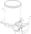
图1为本发明一实施例的阀体装置安装于食品加工机的结构示意图;1 is a schematic structural diagram of a valve body device installed in a food processor according to an embodiment of the present invention;
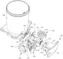
图2为图1中的结构的支架脱离阀座状态下的结构示意图;FIG. 2 is a schematic structural diagram of the structure in FIG. 1 when the support is separated from the valve seat;
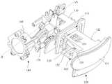
图3为图1中的结构的分解结构示意图;Fig. 3 is the exploded structure schematic diagram of the structure in Fig. 1;
图4为图1中的阀体装置的立体结构示意图;FIG. 4 is a schematic three-dimensional structure diagram of the valve body device in FIG. 1;
图5为图4中A-A处的剖视图;Fig. 5 is the sectional view at A-A place in Fig. 4;
图6为图5中B-B处的剖视图;Fig. 6 is the sectional view at B-B place in Fig. 5;
图7为图4中的阀体装置的一视角的分解结构示意图;FIG. 7 is a schematic exploded structural diagram of the valve body device in FIG. 4 from a perspective;
图8为图4中的阀体装置的另一视角的分解结构示意图;FIG. 8 is a schematic exploded structural diagram of the valve body device in FIG. 4 from another perspective;
图9为本发明食品加工机的控制方法的一实施例的流程示意图;9 is a schematic flowchart of an embodiment of a control method for a food processor of the present invention;
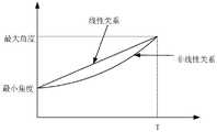
图10为本发明实施例涉及的挤压机构与运动时长的一种关系示意图;10 is a schematic diagram of a relationship between the extrusion mechanism and the movement duration involved in the embodiment of the present invention;
图11为本发明实施例涉及的挤压机构与运动时长的另一种关系示意图;11 is another schematic diagram of the relationship between the extrusion mechanism and the movement duration involved in the embodiment of the present invention;
图12为本发明食品加工机的控制方法的一实施例中的一种可选实施方式的流程示意图;FIG. 12 is a schematic flowchart of an optional embodiment of an embodiment of a control method for a food processor of the present invention;
图13为本发明食品加工机的控制方法的另一实施例的流程示意图。FIG. 13 is a schematic flowchart of another embodiment of the control method of the food processor of the present invention.
附图标号说明:Description of reference numbers:
本发明目的的实现、功能特点及优点将结合实施例,参照附图做进一步说明。The realization, functional characteristics and advantages of the present invention will be further described with reference to the accompanying drawings in conjunction with the embodiments.
具体实施方式Detailed ways
应当理解,此处所描述的具体实施例仅仅用以解释本发明,并不用于限定本发明。It should be understood that the specific embodiments described herein are only used to explain the present invention, but not to limit the present invention.
本发明所述的食品加工机的控制方法,应用于食品加工机The control method of the food processing machine of the present invention is applied to the food processing machine
在一实施方式中,食品加工机设置有阀体装置100,食品加工机具有排料口201,阀体装置100包括阀座110、支架120、排料管130以及挤压机构140。阀座110能安装到食品加工机上,如图中示出的结构中,阀座110可以是采用金属材质并通过铸造方式生产制成,或者是塑料材质通过注塑成型,食品加工机包括容器200,容器200上开设有排料口201,容器200的外壁上连接有连接柱202,其中,容器200可以采用金属材质通过铸造方式生产制成,连接柱202可以是与容器200为一体成型,阀座110上设置有连接孔113,阀座110通过例如螺丝或者螺栓等连接件与连接孔113和连接柱202的配合可拆卸地固定在一起。支架120的材质可以是与阀座110的材质相同,排料管130安装于支架120,排料管130能够对接排料口201,排料管130优选具有弹性变形恢复能力的软管,例如可以是采用食品级硅胶材质、橡胶材质等。挤压机构140在使用过程中能与排料管130接触,从而挤压机构140使得排料管130在自然导通状态或者受力闭合状态之间切换,也即挤压机构140能接触并作用于排料管130的外壁,通过挤压机构140施加外力,可以使得排料管130产生形变,导致其内部的通道导通,并且在挤压撤掉外力的情况下,排料管130可以依靠其自身的形变恢复能力,到达其自然状态下导通的情况。阀体装置100,在使用过程中可以通过挤压机构140作用于排料管130,使得食品加工机在容器200中进行搅打加工食材时,因为排出路径关闭而不会产生泄漏,而在食材加工完成后,通过挤压机构140释放排料管130,使得容器200中加工好了的食材可以通过排料口201以及排料管130排出。即可以通过挤压机构140控制排浆阀在导通状态和闭合状态之间切换。In one embodiment, the food processor is provided with a
在长时间使用过程中,流体的食材或者食材中的颗粒残渣容易粘附在排料管130的内壁或者滞留在排料口201和排料管130的接合处,久而久之,这些食材会有发霉、变质的变化趋势,这将对接下来的食品制作产生食品安全问题。为此,为了实现对这些异物食材清洗方便,在将排料管130安装于支架120的基础上,进一步地将支架120与阀座110活动连接,而且所述支架120能相对于阀座110移动,以带动排料管130进入阀座110并与排料口201对接,或者带动排料管130退出阀座110并与排料口201断开。也即排料管130与支架120联动,在通过支架120带动排料管130退出阀座110后,在使用过程中可以至少对支架120以及支架120上的排料管130进行冲洗,可以有效清除排料管130上的食材残渣,降低了因为长时间使用时,食材残渣出现霉变的可能性。During long-term use, the fluid ingredients or the particulate residues in the ingredients tend to adhere to the inner wall of the
本实施方式提出的食品加工机,通过设置挤压机构140,作用于排料管130以实现排料管130的导通和关闭,因为挤压机构140在挤压过程中只会作用于排料管130的外壁,而不会像传统的阀结构,通过阀芯伸入到排料管130中进行导通和关闭的控制,因此避免了食材残渣滞留在阀芯上的情况,并且进一步将排料管130安装在支架120上,而且支架120能相对于阀座110活动,以能将排料管130带出阀座110,从而较为方便地将排料管130进行冲洗干净,如此,从多个方面提升了食品加工机使用过程中的卫生安全性。In the food processing machine proposed in this embodiment, the
在另一实施方式中,排料管130与支架120可拆卸连接,当所述支架120带动所述排料管130退出阀座110后,排料管130能从支架120拆出。如此设置,则在清洗过程中,可以直接将排料管130从支架120上取出,这样清洗操作更为便利,清洗时更为彻底。在其他实施方式中,还可以将排料管130与支架120设置为固定连接方式,则在清洗过程中,支架120和排料管130将可以是一同进行拆洗。进一步地,支架120能带动排料管130一同由阀座110抽离在排料管130和支架120在固定连接或者可拆卸连接的情况下,都可以将支架120设置为可以从阀座110抽离的方案,这样设置,则在支架120和排料管130冲洗过程中,可以在阀座110以外的地方进行,冲洗操作更为便利。而在其他实施方式中,支架120与阀座110活动连接的方式,也可以是支架120不能完全从阀座110上抽离的方案,例如,支架120与阀座110是通过枢轴进行转动连接的方案,支架120可以带动排料管130绕枢轴进行翻转而进入或者脱出阀座110,进而方便进行冲洗。接下来的内容,还是以支架120能带动排料管130一同由阀座110抽离的方案进行进一步展开。In another embodiment, the
在一实施方式中,所述阀座110形成有导槽111,支架120能沿导槽111滑动,以带动排料管130进入阀座110内而与所述排料口201对接,或者,支架120能沿导槽111活动,而带动排料管130一同由阀座110抽离,使得排料管130与排料口201断开,使得支架120和排料管130能够方便进行冲洗操作。In one embodiment, the
具体地,的阀座110为一中空的框体构造,其内部形成有在朝向容器200的方向上两端贯通的所述导槽111,其中,作为一种较佳的结构形式,导槽111的底部开设有沿其长度方向延伸并且向下贯通的开口,该开口可以用于避位排料管130,则在支架120带动排料管130抽拉进出阀座110时,阀座110的结构不会与排料管130产生干涉。上述的连接孔113开设于阀座110靠近容器200的端部,支架120包括有端盖部121和主体部122两部分,其中主体部122呈长形的方柱状,端盖部121封盖在主体部122的端部,其中导槽111的形状与主体部122的形状相适配,端盖部121的覆盖面积要大于导槽111的入口面积,在使用过程中,主体部122插入到导槽111内,而端盖部121外露于导槽111,使用时,可以通过施力于端盖部121而方便将对支架120进行抽拉操作。Specifically, the
进一步地,所述挤压机构140包括驱动件160以及与驱动件160传动连接的挤压组件150,挤压组件150至少部分伸入导槽111内,挤压组件150在驱动件160的驱动下,能使排料管130受力闭合,优选采用自动驱动挤压组件150进行打开和关闭排料管130的方案,其中,驱动件160可以由食品加工机进行供电,并接入到食品加工机的控制回路中,这样设置的好处在于,可以将阀体装置100的通断控制与食品加工机的自动烹饪或者清洗功能进行结合,如此使用过程中自动化程度高,使用更为便利。Further, the
参照图4至图8,在一实施方式中,所述挤压组件150包括第一压板151及第二压板152,所述排料管130进入所述阀座110时,由第一压板151与所述第二压板152之间穿过,驱动件160能驱动所述第一压板151与第二压板152中的至少一者靠近排料管130移动,以配合挤压排料管130。本实施例可以是在驱动件160的驱动下,第一压板151或者第二压板152进行动作,使得第一压板151和第二压板152之间的距离变小从而实现对排料管130进行内部通道关闭控制,当然,也可以是通过驱动件160同时驱动第一压板151和第二压板152进行相向运动,以实现快速关闭排料管130的目的。可以理解的,在其他实施例中,挤压组件150也可以是设置有一个压板的结构形式,通过该压板在下压过程中与阀座110或者支架120进行配合,从而实现对排料管130内部通道的关闭操作。为了确保在关闭排料管130内部通道操作时的可靠性,优选采用第一压板151和第二压板152同时动作的方案,接下来的内容将进一步地对该方案进行详细描述。Referring to FIGS. 4 to 8 , in one embodiment, the
为了能实现第一压板151和第二压板152能够挤压排料管130,在一实施例中,所述支架120形成有安装腔123并设置有与安装腔123连通的第一开口1231、第二开口1232、第三开口1233以及第四开口1234,其中,第一开口1231位于主体部122远离端盖部121的一端,第二开口1232位于主体部122的底面,第三开口1233和第四开口1234则相对设置在主体部122水平方向上相对的两个侧面上,则支架120通过上述安装腔123和多个开口的结构基本成镂空构造。排料管130的两端分别由所述第一开口1231和所述第二开口1232伸出,请参照图6,进一步地,为了实现排料管130的固定,排料管130的伸出第一开口1231的一端以及在排料管130的中部设置有限位筋131构造,限位筋131可以是呈环状并突出与排料管130的表面,并且支架120在安装腔123内凸设有支撑结构,其中,位于排料管130端部的限位筋131构造卡接在第一开口1231的外壁,位于排料管130中部的限位筋131则抵接在安装腔123内部支撑结构背离第一开口1231的一侧,从而排料管130通过两侧卡接限位实现在支架120上的固定,而不易松脱。可以理解的,形成在排料管130端口处的限位筋131,通过厚度增加或者构造上进行相应设计,也可以作为排料管130与排料口201对接的密封圈构造,从而确保对接处的密封性。In order to enable the first
上述的第一压板151和第二压板152通过第四开口1234伸入安装腔123内,并且第一压板151和第二压板152位于排料管130同一侧的端部分别与固定于支架120的转轴153转动连接,由此,第一压板151、第二压板152以及转轴153三者所构成的为一个夹子结构,接下来称之为料管夹,其中,转轴153可以是与支架120通过一体注塑或者铸造成型,也可以是通过其他座体结构安装到支架120的侧壁上,所述驱动件160在支架120和排料管130进入阀座110后,能由第三开口1233伸入安装腔123内以接触第一压板151和所述第二压板152的至少其中之一,以通过改变第一压板151与第二压板152之间的夹角而挤压排料管130。本实施例通过以上结构设计,则在使用过程中,可以实现支架120带动排料管130从阀座110进行抽离,进而方便进行清洗操作。The above-mentioned first
进一步地,请再次参照图4和图5,所述挤压机构140还包括与驱动件160连接的驱动夹170,阀座110设置有连通导槽111的限位槽112,所述驱动件160能驱动驱动夹170沿限位槽112移动以进入导槽111或者退出导槽111。Further, please refer to FIG. 4 and FIG. 5 again, the
在一实施例中,驱动夹170包括第一驱动板171、第二驱动板172和连接第一驱动板171与所述第二驱动板172的连接板,第一驱动板171和第二驱动板172分别具有相对设置的第一斜面173和第二斜面174,第一斜面173与所述第二斜面174之间的距离在靠近所述转轴153的方向上逐渐减小;In one embodiment, the driving
其中,所述驱动件160驱动所述驱动夹170进入所述导槽111时,料管夹中的所述第一压板151与所述第二压板152远离所述转轴153的一端分别与所述第一斜面173与所述第二斜面174滑动接触,并且所述第一斜面173和所述第二斜面174驱使所述第一压板151和第二压板152之间的夹角变小。Wherein, when the driving
结合上面的内容,通过同时驱动第一压板151和第二压板152进行运动以能稳靠的进行夹持关闭排料管130,因此驱动夹170设置为第一驱动板171和第二驱动板172的结构形式。在图中示出的方案中,在驱动夹170的连接板中开设有螺孔,而驱动件160为电机,电机的电机轴上安装有螺杆,通过电机带动螺杆以推动驱动夹170移动,驱动夹170因为限位槽112的设置,只能进行朝向料管夹的转轴153靠近的以及远离料管夹的转轴153的线性运动,进一步地,还以穿过转轴153以及电机的电机轴的虚拟连线为基准,其中,定义在自然状态下,第一压板151与第二压板152之间能张开的最大角度(即为料管夹能张开的最大角度)为α,而第一驱动板171与第二驱动板172之间能张开的最大角度(即为驱动夹170能张开的最大角度)为β,在一实施例中,为了实现整体结构较为紧凑,体积较小,将β的角度设置为大于α,如此,在驱动夹170朝向转轴153运动时,第一压板151或第二压板152的端部外壁面将首先接触第一驱动板171或者第二驱动板172的第一斜面173或者第二斜面174,驱动夹170进一步地运动时,将使得第一压板151和第二压板152相对转轴153进行转动进行相互靠近以夹紧排料管130。进一步地,为了确保在驱动夹170驱动料管夹过程中,第一压板151与第二压板152在开合变形过程稳定可靠,其中,α+β<180°,通过该参数设置,在驱动夹170朝向料管夹运动时,料管夹的两个压板能够顺利的沿着驱动夹170上的两个斜面运动而相互靠近以夹紧排料管130,而不是角度扩张的运动。以上设置,可以实现在排料管130打开和关闭的操作过程较为稳定可靠。In combination with the above content, by simultaneously driving the first
进一步地,为了实现挤压机构140在上述动作过程时,较为顺畅。优选在自然状态下,当支架120带动排料管130插入导槽111时,支架120的主体部122与导槽111之间为松配合,并且为了避免零部件之间产生干涉,定义第一压板151或第二压板152的端部与导槽111的内壁或者限位槽112的槽口的间距(或者公差)为ΔC,其中ΔC≥0,定义第一驱动板171或第二驱动板172的端部与导槽111的内壁或者限位槽112的槽口的间距(或者公差)为ΔL,其中,ΔL≥0。Further, in order to realize the smoothness of the
可以理解的,上述内容介绍的是挤压机构140设置为以电机驱动两个压板向下运动进行关闭排料管130的方案,在其他实施例中,还可以是将驱动件160设置为气缸,以气缸推动驱动夹170直接进行线性移动以实现上述功能,或者在单独驱动第一压板151或者第二压板152运动时,可以是直接使用电机或者气缸在以上结构的基础上,直接作用第一压板151或者第二压板152进行排料管130的通断操作。It can be understood that the above content describes a solution in which the
以上内容介绍了排料管130通过拆装设计而方便清洗的内容,在一实施例中,为了实现排料管130对接排料口201密封性较高,不易在二者的连接处产生泄漏,还在阀座110和所述支架120之间还设置有锁定结构,支架120带动排料管130进入阀座110并与所述排料口201对接时,所述支架120通过所述锁定结构相对固定于所述阀座110。的锁定结构主要是提供一个预紧力,避免在使用过程中,因为排料过程中,或者由于食品加工机的振动,导致支架120带动排料管130滑移进而导致对接处出现泄漏的情况。The above content introduces the convenient cleaning of the
在一实施例中,所述锁定结构包括设置在所述阀座110上的第一锁定部114以及设置在所述支架120上的第二锁定部124,所述第一锁定部114在所述支架120带动所述排料管130进入所述阀座110并与所述排料口201对接时,与所述第二锁定部124连接。本实施例,第一锁定部114为形成于阀座110上的卡槽,第二锁定部124为形成在所述支架120上的卡勾。通过卡勾和卡槽的配合,在实现排料管130和排料口201对接后,支架120与阀座110进行相对固定的同时,在需要将排料管130抽出清洗过程中,也较为容易实现支架120和阀座110的解锁。可以理解的,在其他实施例中,锁定结构中的第一锁定部114和第二锁定部124,可以分别是两个安装在支架120和阀座110上的磁性块,或者是分别安装在支架120和阀座110上的插销和与插销配合限位的槽或孔的构造,或者是例如弹簧锁和锁位的构造。In one embodiment, the locking structure includes a
本发明还提出一种食品加工机,该食品加工机包括容器200和阀体装置100,该阀体装置100的具体结构参照上述实施例,由于本食品加工机采用了上述所有实施例的全部技术方案,因此至少具有上述实施例的技术方案所带来的所有有益效果,在此不再一一赘述。The present invention also provides a food processing machine, which includes a
其中,食品加工机可以是市面上例如豆浆机、料理机、破壁机、榨汁机、搅拌机、咖啡机等机器。Wherein, the food processor may be a machine on the market, such as a soybean milk machine, a food processor, a wall breaker, a juicer, a blender, a coffee machine, and the like.
参照图9,基于如上任一实施方式的食品加工机,在本发明食品加工机的控制方法的一实施例中,所述食品加工机的控制方法包括以下步骤:9 , based on the food processor of any of the above embodiments, in an embodiment of the control method of the food processor of the present invention, the control method of the food processor includes the following steps:
步骤S10、在接收到控制指令时,控制所述驱动装置驱动所述挤压机构,以使所述排浆阀在导通状态和闭合状态之间切换;Step S10, when receiving a control command, control the driving device to drive the pressing mechanism, so as to switch the slurry discharge valve between an on state and a closed state;
步骤S20、获取所述挤压机构的行程控制参数,其中,所述行程控制参数包括所述挤压机构的运动时长和/或所述挤压机构的当前位置;Step S20, acquiring the stroke control parameters of the extrusion mechanism, wherein the stroke control parameters include the movement duration of the extrusion mechanism and/or the current position of the extrusion mechanism;
步骤S30、在所述程控制参数满足预设条件时,控制所述驱动装置停止驱动所述挤压机构运动。Step S30 , when the process control parameter satisfies a preset condition, control the driving device to stop driving the extruding mechanism to move.
在本实施例中,食品加工机可以接收控制指令。其中,所述控制指令是包括排浆指令或者排浆阀闭合指令。当接收到排浆指令时,通过控制驱动装置驱动挤压机构运动,以使得排浆阀进入导通状态。从而使得食品加工机中的浆体可以从排浆阀中流出。当接收到排浆阀闭合指令时,则通过控制驱动装置驱动挤压机构运动,以使得排浆阀进入闭合状态,从而使得食品加工机中的浆体,无法从排浆阀中流出。In this embodiment, the food processor may receive control instructions. Wherein, the control command includes a slurry discharge command or a slurry valve closing command. When receiving the ejection command, the extruding mechanism is driven to move by controlling the driving device, so that the ejection valve enters the conducting state. This allows the slurry in the food processor to flow out of the drain valve. When receiving the closing command of the slurry valve, the extruding mechanism is driven to move by the control driving device, so that the slurry valve enters a closed state, so that the slurry in the food processor cannot flow out of the slurry valve.
具体地,当接收到所述控制指令时,可以控制驱动装置驱动所述挤压机构超第一方向运动或者朝第二方向运动。其中,,控制所述驱动装置驱动所述挤压机构向第一方向运动,以使所述排浆阀切换至导通状态,在接收到所述排浆阀闭合指令时,控制所述驱动装置驱动所述挤压机构向第二方向运动,以使所述排浆阀切换至闭合状态。Specifically, when the control instruction is received, the driving device can be controlled to drive the pressing mechanism to move beyond the first direction or move toward the second direction. Wherein, the driving device is controlled to drive the extrusion mechanism to move in the first direction, so that the slurry valve is switched to the conducting state, and the driving device is controlled when receiving the closing instruction of the slurry valve. The pressing mechanism is driven to move in the second direction, so that the slurry discharge valve is switched to a closed state.
在驱动所述挤压机构运动的过程中,排浆阀还可以获取所述挤压机构的行程控制参数,其中,所述行程控制参数包括所述挤压机构的运动时长和/或所述挤压机构的当前位置。进而在所述程控制参数满足预设条件时,控制所述驱动装置停止驱动所述挤压机构运动。可选地,所述预设条件包括:所述挤压机构的运动时长大于或者等于预设时长,和/或所述挤压机构的当前位置处于预设的闭合位置或者导通位置。In the process of driving the extrusion mechanism to move, the slurry valve may also acquire stroke control parameters of the extrusion mechanism, wherein the stroke control parameters include the movement duration of the extrusion mechanism and/or the extrusion mechanism. current position of the pressing mechanism. Further, when the process control parameter meets a preset condition, the driving device is controlled to stop driving the extruding mechanism to move. Optionally, the preset conditions include: the movement duration of the pressing mechanism is greater than or equal to the predetermined duration, and/or the current position of the pressing mechanism is in a predetermined closed position or a conduction position.
为使本领域技术人员可以更好地理解本发明权利要求的保护范围,以下通过一些具体示例,对本发明进行进一步地解释说明。In order for those skilled in the art to better understand the protection scope of the claims of the present invention, the present invention will be further explained below through some specific examples.
示例1,在一实施方式中,食品加工机设置有位置检测传感器。所述位置检测创器用户获取挤压机构的当前位置。当接收到排浆指令时检测挤压机构的当前位置,进而在其当前位置未到达导通位置时,食品加工机可以控制挤压机构向第一方向运动,在所述当前位置到达导通位置时,判定排浆阀已经完全打开,从而控制挤压机构停止运动。或者,接收到排浆阀闭合指令时,实时获取挤压机构的当前位置,挤压机构未达到预设的闭合位置时,控制其向第二方向运动,并在挤压机构的当前位置到达预设的闭合位置时,控制挤压机构停止运动。Example 1, in one embodiment, a food processor is provided with a position detection sensor. The position detection tool user obtains the current position of the compression mechanism. When the current position of the extrusion mechanism is detected when receiving the pulp discharge command, and when the current position does not reach the conduction position, the food processor can control the extrusion mechanism to move in the first direction and reach the conduction position at the current position. When it is determined that the slurry valve has been fully opened, the extruding mechanism is controlled to stop moving. Or, when receiving the closing command of the discharge valve, the current position of the extrusion mechanism is obtained in real time, and when the extrusion mechanism does not reach the preset closing position, it is controlled to move in the second direction, and the current position of the extrusion mechanism reaches the preset position. When the closed position is set, the control extrusion mechanism stops moving.
示例2,在一实施方式中,当挤压机构达到最大角度时,排浆阀处于导通状态。挤压机构处于最小角度时,排浆阀处于闭合状态。其中,参照图10给出的,挤压机构向第一方向运动时,挤压机构的角度值与运动时长T的关系,以及参照图11给出的,挤压机构向第二方向运动时,挤压机构的角度值与运动时长T的关系。其中,在图10中,挤压机构的运动时长T于角度值之间呈正相关。可以理解的是,根据驱动机构和挤压机构的运动方式不同,挤压机构的运动时长T于角度值之间可以线性关系,也可以是非线性关系。同理,图11中给出的挤压机构的运动时长T于角度值之间关系,也可以是线性关系或者非线性关系。进一步,基于图10和11给出的挤压机构的运动时长T于角度值之间关系,可以所述挤压机构向第一方向运动的运动时长大于或者等于第一时长,时判定挤压机构对应的角度值为最大角度,即排浆阀已经处于完全导通状态。或者所述挤压机构向第二方向运动的运动时长大于或者等于第二时长时,判定挤压机构对应的角度值为最小角度,即排浆阀已经处于完全闭合状态。因此,可以将上述预设条件设置为所述挤压机构向第一方向运动的运动时长大于或者等于第一时长;或者所述挤压机构向第二方向运动的运动时长大于或者等于第二时长。Example 2, in one embodiment, when the extrusion mechanism reaches the maximum angle, the slurry discharge valve is in an on state. When the extrusion mechanism is at the minimum angle, the discharge valve is closed. Among them, as shown in FIG. 10, when the extrusion mechanism moves in the first direction, the relationship between the angle value of the extrusion mechanism and the movement duration T, and with reference to FIG. 11, when the extrusion mechanism moves in the second direction, The relationship between the angle value of the extrusion mechanism and the movement duration T. Among them, in FIG. 10 , the movement duration T of the pressing mechanism is positively correlated with the angle value. It can be understood that, according to the different movement modes of the driving mechanism and the pressing mechanism, the movement duration T of the pressing mechanism and the angle value may have a linear relationship or a non-linear relationship. Similarly, the relationship between the movement duration T of the extrusion mechanism and the angle value shown in FIG. 11 may also be a linear relationship or a nonlinear relationship. Further, based on the relationship between the movement duration T of the extrusion mechanism and the angle value given in FIGS. 10 and 11 , the extrusion mechanism can be determined when the movement duration of the extrusion mechanism in the first direction is greater than or equal to the first duration. The corresponding angle value is the maximum angle, that is, the discharge valve is already in a fully conducting state. Or when the movement duration of the extrusion mechanism in the second direction is greater than or equal to the second duration, it is determined that the angle value corresponding to the extrusion mechanism is the minimum angle, that is, the discharge valve is already in a fully closed state. Therefore, the above preset conditions can be set as the movement duration of the pressing mechanism in the first direction is greater than or equal to the first duration; or the movement duration of the pressing mechanism in the second direction is greater than or equal to the second duration .
需要说明的是,在示例2中,上述第一时长和所述第二时长可以相等,也可以不相等。其中,所述第一时长和第二时长一般设置为大于或等于0.5s。例如,可以设置为[1s,10s]中的任一数值。在一较佳实施方式中,第一时长和第二时长设置为处于[1s,6s]区间内。It should be noted that, in Example 2, the above-mentioned first duration and the second duration may or may not be equal. Wherein, the first duration and the second duration are generally set to be greater than or equal to 0.5s. For example, it can be set to any value in [1s, 10s]. In a preferred embodiment, the first duration and the second duration are set to be within the interval of [1s, 6s].
示例3,基于上述示例2,参照图12,所述控制所述驱动装置停止驱动所述挤压机构运动的步骤之后,还包括:Example 3, based on the above example 2, referring to FIG. 12 , after the step of controlling the driving device to stop driving the movement of the pressing mechanism, further includes:
步骤S40、在停止驱动所述挤压机构向第一方向运动时,控制所述驱动装置驱动所述挤压装置在当前位置保持第三时长;或者在停止驱动所述挤压机构向第二方向运动时,控制所述驱动装置驱动所述挤压装置在当前位置保持第四时长。Step S40, when stopping driving the pressing mechanism to move in the first direction, control the driving device to drive the pressing device to maintain the current position for a third period of time; or stop driving the pressing mechanism to the second direction During movement, the driving device is controlled to drive the pressing device to maintain the current position for a fourth period of time.
在示例3中,在停止驱动挤压机构向第一方向或者第二方向运动时,为了确保释放掉机构的运动惯性,还可以在停止驱动所述挤压机构向第一方向运动时,控制所述驱动装置驱动所述挤压装置在当前位置(停止向第一方向运动的位置,即停止位置)保持第三时长,或者在停止驱动所述挤压机构向第二方向运动时,控制所述驱动装置驱动所述挤压装置在当前位置(停止向第二方向运动的位置,即停止位置)保持第四时长。In Example 3, when stopping the driving of the pressing mechanism to move in the first direction or the second direction, in order to ensure that the motion inertia of the mechanism is released, when the pressing mechanism is stopped to move in the first direction, control all The driving device drives the pressing device to maintain the current position (the position where the movement in the first direction is stopped, that is, the stop position) for a third period of time, or when the pressing mechanism is stopped to move in the second direction, controls the The driving device drives the pressing device to maintain the current position (the position where the movement in the second direction is stopped, that is, the stop position) for a fourth period of time.
需要说明的是,在示例3中,所述第三时长和所述第四时长可以设置为相等也可以设置为不相等。其中,所第三时长和所述第四时长均大于或者等于0.1s。例如,所述第三时长和所述第四时长可以设置于[0.5s,10s]区间内。在一较佳实施例中,所述第三时长和所述第四时长设置于[1s,6s]区间内。It should be noted that, in Example 3, the third duration and the fourth duration may be set to be equal or unequal. Wherein, the third duration and the fourth duration are both greater than or equal to 0.1s. For example, the third duration and the fourth duration may be set within an interval of [0.5s, 10s]. In a preferred embodiment, the third duration and the fourth duration are set in the interval of [1s, 6s].
示例4,基于上述示例1,以及示例2和示例3中的任一个,食品加工机可以设置有运动时长和位置检测两种机制,即在挤压机构向第一方向运动时,在检测到运动时长大于或者等于第一时长,且当前位置处于导通位置时,判定所述程控制参数满足预设条件,控制所述驱动装置停止驱动所述挤压机构运动。或者在挤压机构向第二方向运动时,在检测到运动时长大于或者等于第二时长,且当前位置处于闭合位置时,判定所述程控制参数满足预设条件,控制所述驱动装置停止驱动所述挤压机构运动。Example 4, based on the above example 1, and any one of the examples 2 and 3, the food processor may be provided with two mechanisms of movement duration and position detection, that is, when the extrusion mechanism moves in the first direction, when the movement is detected. When the duration is greater than or equal to the first duration, and the current position is in the conducting position, it is determined that the process control parameter satisfies a preset condition, and the driving device is controlled to stop driving the extruding mechanism to move. Or when the extrusion mechanism moves in the second direction, when it is detected that the movement duration is greater than or equal to the second duration, and the current position is in the closed position, it is determined that the process control parameters meet the preset conditions, and the driving device is controlled to stop driving. The extrusion mechanism moves.
需要说明的是,图9并不用于限定步骤S10和步骤S20的执行顺序,即在接收到控制指令时,获取所述挤压机构的行程控制参数和控制所述驱动装置驱动所述挤压机构可以同时执行,或者在接收到控制指令时,先获取所述挤压机构的行程控制参数,再控制所述驱动装置驱动所述挤压机构。It should be noted that FIG. 9 is not used to limit the execution sequence of steps S10 and S20, that is, when a control command is received, the stroke control parameters of the extrusion mechanism are acquired and the driving device is controlled to drive the extrusion mechanism. It can be performed at the same time, or when a control instruction is received, the stroke control parameters of the pressing mechanism are obtained first, and then the driving device is controlled to drive the pressing mechanism.
在本实施例中,在接收到控制指令时,控制所述驱动装置驱动所述挤压机构,以使所述排浆阀在导通状态和闭合状态之间切换,进而获取所述挤压机构的行程控制参数,在所述程控制参数满足预设条件时,控制所述驱动装置停止驱动所述挤压机构运动,由于可以通过控制参数判定控制所述驱动装置停止驱动所述挤压机构运动的时机,从而使得排浆阀的行程控制更加准确,避免了手动控制排浆阀行程,导致排浆阀机扩的运动行程不到位,排浆阀出现漏液或者排浆不畅的现象发生,达成了在提升食品加工的使用便捷性的同时,提高排浆阀的性能的效果。In this embodiment, when a control command is received, the driving device is controlled to drive the pressing mechanism, so that the slurry discharge valve is switched between an on state and a closed state, and then the pressing mechanism is acquired When the stroke control parameters meet the preset conditions, the driving device is controlled to stop driving the movement of the extrusion mechanism, because the driving device can be controlled to stop driving the movement of the extrusion mechanism by determining the control parameters. Therefore, the stroke control of the discharge valve is more accurate, and the manual control of the stroke of the discharge valve is avoided, resulting in the insufficient movement stroke of the discharge valve machine expansion, and the phenomenon of liquid leakage or poor discharge of the discharge valve. It achieves the effect of improving the performance of the slurry valve while improving the convenience of food processing.
参照图13,基于上述实施例,在另一实施例中,所述步骤S10之前,还包括:Referring to FIG. 13, based on the above-mentioned embodiment, in another embodiment, before the step S10, the method further includes:
步骤S50、接收用户下发的所述控制指令;或者在检测到所述食品加工机上电、接收到上料指令和/或所述食品加工机处于食品加工状态时,触发所述排浆阀闭合指令。Step S50, receiving the control instruction issued by the user; or triggering the closing of the slurry valve when it is detected that the food processing machine is powered on, a feeding instruction is received, and/or the food processing machine is in a food processing state instruction.
在本实施例中,所述食品加工机可以设置有用户接口。其中,所述用户接口可以设置为案件或者触摸屏或者遥控装置等等。在一些实施方式中,用户接口还可以是食品加工机,其中食品加工机可以通过局域网或者互联网与食品加工机通信连接,使得食品加工机可以以食品加工机为用户接口,与用户进行交互。In this embodiment, the food processor may be provided with a user interface. Wherein, the user interface can be set as a case or a touch screen or a remote control device and so on. In some embodiments, the user interface can also be a food processor, wherein the food processor can communicate with the food processor through a local area network or the Internet, so that the food processor can use the food processor as a user interface to interact with the user.
作为一种可选实施方式,用户可以通过用户接口向食品加工机发送控制指令。当食品加工机接收到所述控制指令时,可以执行步骤S10-S30。As an optional implementation, the user may send control commands to the food processor through the user interface. When the food processor receives the control instruction, steps S10-S30 may be executed.
作为另一中实施方式,食品加工机可以自主触发控制指令。例如,当食品加工机设置为在断电状态下,排浆阀处于导通或者半导通状态时,为避免上电工作后,用户未下发排浆阀闭合指令,就加入待加工材料,导致待加工材料从排浆口流出的现象发生,可以在机器上电后,自动触发排浆阀闭合指令。可选地,为了避免待加工材料流出,还可以在接收到上料指令和/或所述食品加工机处于食品加工状态时,自主触发所述排浆阀闭合指令。As another embodiment, the food processor can autonomously trigger the control command. For example, when the food processor is set to be in a power-off state and the discharge valve is in a conducting or semi-conducting state, in order to prevent the user from issuing a closing command for the discharge valve after power-on, the material to be processed is added. The phenomenon that causes the material to be processed to flow out of the discharge port occurs, and the closing command of the discharge valve can be automatically triggered after the machine is powered on. Optionally, in order to prevent the material to be processed from flowing out, when a feeding instruction is received and/or the food processing machine is in a food processing state, the closing instruction of the slurry discharge valve may be triggered autonomously.
可选地,在本实施方式中,为了避免食品加工机频繁触发排浆阀闭合指令,还可以在自出触发排浆阀闭合指令前,先检测排浆阀的状态,进而若其状态为闭合状态,则不触发排浆阀闭合指令,否则自主触发排浆阀闭合指令。Optionally, in this embodiment, in order to prevent the food processor from frequently triggering the closing command of the discharge valve, it is also possible to detect the state of the discharge valve before triggering the closing command of the discharge valve, and then if its state is closed. state, the closing command of the slurry valve will not be triggered, otherwise the closing command of the slurry valve will be triggered autonomously.
在本实施例公开的技术方案中,接收用户下发的所述控制指令;或者在检测到所述食品加工机上电、接收到上料指令和/或所述食品加工机处于食品加工状态时,触发所述排浆阀闭合指令。这样可以减少用户的操作步骤,提高食品加工机的使用便捷性。In the technical solution disclosed in this embodiment, the control instruction issued by the user is received; or when it is detected that the food processing machine is powered on, a feeding instruction is received, and/or the food processing machine is in a food processing state, Trigger the slush valve closing command. In this way, the user's operation steps can be reduced, and the convenience of use of the food processor can be improved.
此外,本发明实施例还提出一种食品加工机,所述食品加工机包括排浆阀、挤压机构、驱动装置、存储器、处理器及存储在所述存储器上并可在所述处理器上运行的食品加工机的控制程序,所述挤压机构与所述驱动装置连接,其中,所述挤压机构设置为在驱动装置的驱动下,所述食品加工机的控制程序被所述处理器执行时实现如上各个实施例所述的食品加工机的控制方法的步骤。In addition, an embodiment of the present invention also provides a food processing machine, the food processing machine includes a slurry valve, a pressing mechanism, a driving device, a memory, a processor, and storage on the memory and on the processor A control program of a food processor in operation, the extrusion mechanism is connected to the drive device, wherein the extrusion mechanism is arranged to be driven by the drive device, and the control program of the food processor is controlled by the processor When executed, the steps of the control method of the food processing machine described in each of the above embodiments are realized.
此外,本发明实施例还提出一种计算机可读存储介质,所述计算机可读存储介质上存储有食品加工机的控制程序,所述食品加工机的控制程序被处理器执行时实现如上各个实施例所述的食品加工机的控制方法的步骤。In addition, an embodiment of the present invention further provides a computer-readable storage medium, where a control program of a food processor is stored on the computer-readable storage medium, and each of the above implementations is implemented when the control program of the food processor is executed by a processor The steps of the control method of the food processor described in the example.
需要说明的是,在本文中,术语“包括”、“包含”或者其任何其他变体意在涵盖非排他性的包含,从而使得包括一系列要素的过程、方法、物品或者系统不仅包括那些要素,而且还包括没有明确列出的其他要素,或者是还包括为这种过程、方法、物品或者系统所固有的要素。在没有更多限制的情况下,由语句“包括一个……”限定的要素,并不排除在包括该要素的过程、方法、物品或者系统中还存在另外的相同要素。It should be noted that, herein, the terms "comprising", "comprising" or any other variation thereof are intended to encompass non-exclusive inclusion, such that a process, method, article or system comprising a series of elements includes not only those elements, It also includes other elements not expressly listed or inherent to such a process, method, article or system. Without further limitation, an element qualified by the phrase "comprising a..." does not preclude the presence of additional identical elements in the process, method, article or system that includes the element.
上述本发明实施例序号仅仅为了描述,不代表实施例的优劣。The above-mentioned serial numbers of the embodiments of the present invention are only for description, and do not represent the advantages or disadvantages of the embodiments.
通过以上的实施方式的描述,本领域的技术人员可以清楚地了解到上述实施例方法可借助软件加必需的通用硬件平台的方式来实现,当然也可以通过硬件,但很多情况下前者是更佳的实施方式。基于这样的理解,本发明的技术方案本质上或者说对现有技术做出贡献的部分可以以软件产品的形式体现出来,该计算机软件产品存储在如上所述的一个存储介质(如ROM/RAM、磁碟、光盘)中,包括若干指令用以使得一台食品加工机执行本发明各个实施例所述的方法。From the description of the above embodiments, those skilled in the art can clearly understand that the method of the above embodiment can be implemented by means of software plus a necessary general hardware platform, and of course can also be implemented by hardware, but in many cases the former is better implementation. Based on such understanding, the technical solutions of the present invention can be embodied in the form of software products in essence or the parts that make contributions to the prior art, and the computer software products are stored in a storage medium (such as ROM/RAM) as described above. , magnetic disk, optical disk), including several instructions for causing a food processor to perform the method described in the various embodiments of the present invention.
以上仅为本发明的优选实施例,并非因此限制本发明的专利范围,凡是利用本发明说明书及附图内容所作的等效结构或等效流程变换,或直接或间接运用在其他相关的技术领域,均同理包括在本发明的专利保护范围内。The above are only preferred embodiments of the present invention, and are not intended to limit the scope of the present invention. Any equivalent structure or equivalent process transformation made by using the contents of the description and drawings of the present invention, or directly or indirectly applied in other related technical fields , are similarly included in the scope of patent protection of the present invention.
Claims (10)
Priority Applications (1)
| Application Number | Priority Date | Filing Date | Title |
|---|---|---|---|
| CN202110324541.XACN115120112B (en) | 2021-03-25 | 2021-03-25 | Food processor control method, food processor and storage medium |
Applications Claiming Priority (1)
| Application Number | Priority Date | Filing Date | Title |
|---|---|---|---|
| CN202110324541.XACN115120112B (en) | 2021-03-25 | 2021-03-25 | Food processor control method, food processor and storage medium |
Publications (2)
| Publication Number | Publication Date |
|---|---|
| CN115120112Atrue CN115120112A (en) | 2022-09-30 |
| CN115120112B CN115120112B (en) | 2024-11-22 |
Family
ID=83374262
Family Applications (1)
| Application Number | Title | Priority Date | Filing Date |
|---|---|---|---|
| CN202110324541.XAActiveCN115120112B (en) | 2021-03-25 | 2021-03-25 | Food processor control method, food processor and storage medium |
Country Status (1)
| Country | Link |
|---|---|
| CN (1) | CN115120112B (en) |
Citations (6)
| Publication number | Priority date | Publication date | Assignee | Title |
|---|---|---|---|---|
| CN204372286U (en)* | 2014-12-03 | 2015-06-03 | 广州粤有研矿物资源科技有限公司 | A kind of board concentrating box controls pulp-expelling valve automatically |
| CN107319961A (en)* | 2017-07-25 | 2017-11-07 | 九阳股份有限公司 | A kind of food processor rotary valve control method |
| CN107606300A (en)* | 2017-09-22 | 2018-01-19 | 九阳股份有限公司 | A kind of plasma discharge rotary valve control method of food processor |
| CN108056694A (en)* | 2018-01-15 | 2018-05-22 | 北京风语智格物联科技有限公司 | A kind of liquid bottle pumping equipment |
| CN209437079U (en)* | 2018-11-23 | 2019-09-27 | 九阳股份有限公司 | A kind of food processor that drain effect is good |
| CN212186255U (en)* | 2020-03-11 | 2020-12-22 | 广东美的生活电器制造有限公司 | Food processor |
- 2021
- 2021-03-25CNCN202110324541.XApatent/CN115120112B/enactiveActive
Patent Citations (6)
| Publication number | Priority date | Publication date | Assignee | Title |
|---|---|---|---|---|
| CN204372286U (en)* | 2014-12-03 | 2015-06-03 | 广州粤有研矿物资源科技有限公司 | A kind of board concentrating box controls pulp-expelling valve automatically |
| CN107319961A (en)* | 2017-07-25 | 2017-11-07 | 九阳股份有限公司 | A kind of food processor rotary valve control method |
| CN107606300A (en)* | 2017-09-22 | 2018-01-19 | 九阳股份有限公司 | A kind of plasma discharge rotary valve control method of food processor |
| CN108056694A (en)* | 2018-01-15 | 2018-05-22 | 北京风语智格物联科技有限公司 | A kind of liquid bottle pumping equipment |
| CN209437079U (en)* | 2018-11-23 | 2019-09-27 | 九阳股份有限公司 | A kind of food processor that drain effect is good |
| CN212186255U (en)* | 2020-03-11 | 2020-12-22 | 广东美的生活电器制造有限公司 | Food processor |
Also Published As
| Publication number | Publication date |
|---|---|
| CN115120112B (en) | 2024-11-22 |
Similar Documents
| Publication | Publication Date | Title |
|---|---|---|
| US4303110A (en) | Toothpaste dispenser | |
| CN210124549U (en) | Drip-proof horizontal screw extrusion juicer | |
| CN115120112A (en) | Control method for food processor, and storage medium | |
| CN111227735A (en) | Flat mop cleaning tool | |
| CN116687299A (en) | Control method of base station for cleaning equipment | |
| CN214274621U (en) | Valve body device and food processor | |
| CN110604530B (en) | Detergent additive for dishwasher and dishwasher | |
| CN216876082U (en) | Drain valve assembly, cup assembly, and food processor | |
| CN215980935U (en) | Valve body device and food processor | |
| CN216797422U (en) | Processing cup subassembly and food processor | |
| CN212035678U (en) | Water storage tank water discharge structure and dough mixing machine | |
| AU767824B2 (en) | A control strategy for a thermally activated diverter valve used in a washing appliance | |
| CN221753581U (en) | Drain valves and kitchen equipment | |
| CN112982599B (en) | Intelligent closestool with overheat protection function | |
| CN211883668U (en) | Mop bucket | |
| CN216876081U (en) | Arrange thick liquid valve gear, processing cup subassembly and food processor | |
| CN216876083U (en) | Arrange thick liquid valve gear, processing cup subassembly and food processor | |
| JPH0638945Y2 (en) | Solenoid switching valve lead wire fixing device | |
| JPH1028667A (en) | Dishwasher | |
| EP4442179A1 (en) | Milk discharge valve device, processing cup assembly, and food processor | |
| CN222992280U (en) | Concealed drainage valve port for swimming pool cleaning | |
| CN222367640U (en) | Dish washer | |
| CN221813715U (en) | Coffee machine and coffee machine | |
| CN217161674U (en) | Cup cover and cup | |
| CN211834261U (en) | Mop bucket |
Legal Events
| Date | Code | Title | Description |
|---|---|---|---|
| PB01 | Publication | ||
| PB01 | Publication | ||
| SE01 | Entry into force of request for substantive examination | ||
| SE01 | Entry into force of request for substantive examination | ||
| GR01 | Patent grant | ||
| GR01 | Patent grant |