CN115118017A - Open type liquid carbon dioxide energy storage system - Google Patents
Open type liquid carbon dioxide energy storage systemDownload PDFInfo
- Publication number
- CN115118017A CN115118017ACN202211015654.2ACN202211015654ACN115118017ACN 115118017 ACN115118017 ACN 115118017ACN 202211015654 ACN202211015654 ACN 202211015654ACN 115118017 ACN115118017 ACN 115118017A
- Authority
- CN
- China
- Prior art keywords
- carbon dioxide
- energy storage
- communicated
- storage system
- liquid carbon
- Prior art date
- Legal status (The legal status is an assumption and is not a legal conclusion. Google has not performed a legal analysis and makes no representation as to the accuracy of the status listed.)
- Pending
Links
- CURLTUGMZLYLDI-UHFFFAOYSA-NCarbon dioxideChemical compoundO=C=OCURLTUGMZLYLDI-UHFFFAOYSA-N0.000titleclaimsabstractdescription310
- 229910002092carbon dioxideInorganic materials0.000titleclaimsabstractdescription155
- 239000001569carbon dioxideSubstances0.000titleclaimsabstractdescription155
- 239000007788liquidSubstances0.000titleclaimsabstractdescription108
- 238000004146energy storageMethods0.000titleclaimsabstractdescription66
- 238000010248power generationMethods0.000claimsdescription32
- 239000007789gasSubstances0.000claimsdescription28
- 239000002918waste heatSubstances0.000claimsdescription27
- 238000005338heat storageMethods0.000claimsdescription19
- 238000001816coolingMethods0.000claimsdescription15
- 238000000926separation methodMethods0.000claimsdescription14
- 238000011084recoveryMethods0.000claimsdescription12
- UGFAIRIUMAVXCW-UHFFFAOYSA-NCarbon monoxideChemical compound[O+]#[C-]UGFAIRIUMAVXCW-UHFFFAOYSA-N0.000claimsdescription11
- 239000003546flue gasSubstances0.000claimsdescription11
- 238000010438heat treatmentMethods0.000claimsdescription9
- 238000002485combustion reactionMethods0.000claimsdescription4
- 238000011144upstream manufacturingMethods0.000claimsdescription3
- 238000007906compressionMethods0.000abstractdescription8
- 230000005611electricityEffects0.000description8
- 230000006835compressionEffects0.000description6
- OKTJSMMVPCPJKN-UHFFFAOYSA-NCarbonChemical compound[C]OKTJSMMVPCPJKN-UHFFFAOYSA-N0.000description5
- 229910052799carbonInorganic materials0.000description5
- 238000010586diagramMethods0.000description5
- 238000000034methodMethods0.000description5
- 238000005516engineering processMethods0.000description4
- 238000004891communicationMethods0.000description3
- 238000006243chemical reactionMethods0.000description2
- 238000005265energy consumptionMethods0.000description2
- 238000010276constructionMethods0.000description1
- 230000008878couplingEffects0.000description1
- 238000010168coupling processMethods0.000description1
- 238000005859coupling reactionMethods0.000description1
- 230000007547defectEffects0.000description1
- 238000002309gasificationMethods0.000description1
- 239000002440industrial wasteSubstances0.000description1
- 238000012986modificationMethods0.000description1
- 230000004048modificationEffects0.000description1
- 238000004064recyclingMethods0.000description1
- 150000003839saltsChemical class0.000description1
- 230000026676system processEffects0.000description1
Images


Classifications
- H—ELECTRICITY
- H02—GENERATION; CONVERSION OR DISTRIBUTION OF ELECTRIC POWER
- H02J—CIRCUIT ARRANGEMENTS OR SYSTEMS FOR SUPPLYING OR DISTRIBUTING ELECTRIC POWER; SYSTEMS FOR STORING ELECTRIC ENERGY
- H02J15/00—Systems for storing electric energy
- H02J15/006—Systems for storing electric energy in the form of pneumatic energy, e.g. compressed air energy storage [CAES]
- F—MECHANICAL ENGINEERING; LIGHTING; HEATING; WEAPONS; BLASTING
- F01—MACHINES OR ENGINES IN GENERAL; ENGINE PLANTS IN GENERAL; STEAM ENGINES
- F01K—STEAM ENGINE PLANTS; STEAM ACCUMULATORS; ENGINE PLANTS NOT OTHERWISE PROVIDED FOR; ENGINES USING SPECIAL WORKING FLUIDS OR CYCLES
- F01K23/00—Plants characterised by more than one engine delivering power external to the plant, the engines being driven by different fluids
- F01K23/02—Plants characterised by more than one engine delivering power external to the plant, the engines being driven by different fluids the engine cycles being thermally coupled
- F01K23/06—Plants characterised by more than one engine delivering power external to the plant, the engines being driven by different fluids the engine cycles being thermally coupled combustion heat from one cycle heating the fluid in another cycle
- F—MECHANICAL ENGINEERING; LIGHTING; HEATING; WEAPONS; BLASTING
- F01—MACHINES OR ENGINES IN GENERAL; ENGINE PLANTS IN GENERAL; STEAM ENGINES
- F01K—STEAM ENGINE PLANTS; STEAM ACCUMULATORS; ENGINE PLANTS NOT OTHERWISE PROVIDED FOR; ENGINES USING SPECIAL WORKING FLUIDS OR CYCLES
- F01K25/00—Plants or engines characterised by use of special working fluids, not otherwise provided for; Plants operating in closed cycles and not otherwise provided for
- F01K25/08—Plants or engines characterised by use of special working fluids, not otherwise provided for; Plants operating in closed cycles and not otherwise provided for using special vapours
- F01K25/10—Plants or engines characterised by use of special working fluids, not otherwise provided for; Plants operating in closed cycles and not otherwise provided for using special vapours the vapours being cold, e.g. ammonia, carbon dioxide, ether
- F01K25/103—Carbon dioxide
- F—MECHANICAL ENGINEERING; LIGHTING; HEATING; WEAPONS; BLASTING
- F01—MACHINES OR ENGINES IN GENERAL; ENGINE PLANTS IN GENERAL; STEAM ENGINES
- F01K—STEAM ENGINE PLANTS; STEAM ACCUMULATORS; ENGINE PLANTS NOT OTHERWISE PROVIDED FOR; ENGINES USING SPECIAL WORKING FLUIDS OR CYCLES
- F01K7/00—Steam engine plants characterised by the use of specific types of engine; Plants or engines characterised by their use of special steam systems, cycles or processes; Control means specially adapted for such systems, cycles or processes; Use of withdrawn or exhaust steam for feed-water heating
- F01K7/02—Steam engine plants characterised by the use of specific types of engine; Plants or engines characterised by their use of special steam systems, cycles or processes; Control means specially adapted for such systems, cycles or processes; Use of withdrawn or exhaust steam for feed-water heating the engines being of multiple-expansion type
- F—MECHANICAL ENGINEERING; LIGHTING; HEATING; WEAPONS; BLASTING
- F02—COMBUSTION ENGINES; HOT-GAS OR COMBUSTION-PRODUCT ENGINE PLANTS
- F02C—GAS-TURBINE PLANTS; AIR INTAKES FOR JET-PROPULSION PLANTS; CONTROLLING FUEL SUPPLY IN AIR-BREATHING JET-PROPULSION PLANTS
- F02C6/00—Plural gas-turbine plants; Combinations of gas-turbine plants with other apparatus; Adaptations of gas-turbine plants for special use
- F02C6/18—Plural gas-turbine plants; Combinations of gas-turbine plants with other apparatus; Adaptations of gas-turbine plants for special use using the waste heat of gas-turbine plants outside the plants themselves, e.g. gas-turbine power heat plants
- F—MECHANICAL ENGINEERING; LIGHTING; HEATING; WEAPONS; BLASTING
- F04—POSITIVE - DISPLACEMENT MACHINES FOR LIQUIDS; PUMPS FOR LIQUIDS OR ELASTIC FLUIDS
- F04B—POSITIVE-DISPLACEMENT MACHINES FOR LIQUIDS; PUMPS
- F04B25/00—Multi-stage pumps
- F—MECHANICAL ENGINEERING; LIGHTING; HEATING; WEAPONS; BLASTING
- F04—POSITIVE - DISPLACEMENT MACHINES FOR LIQUIDS; PUMPS FOR LIQUIDS OR ELASTIC FLUIDS
- F04B—POSITIVE-DISPLACEMENT MACHINES FOR LIQUIDS; PUMPS
- F04B41/00—Pumping installations or systems specially adapted for elastic fluids
- F04B41/02—Pumping installations or systems specially adapted for elastic fluids having reservoirs
- H—ELECTRICITY
- H02—GENERATION; CONVERSION OR DISTRIBUTION OF ELECTRIC POWER
- H02J—CIRCUIT ARRANGEMENTS OR SYSTEMS FOR SUPPLYING OR DISTRIBUTING ELECTRIC POWER; SYSTEMS FOR STORING ELECTRIC ENERGY
- H02J3/00—Circuit arrangements for AC mains or AC distribution networks
- H02J3/28—Arrangements for balancing of the load in a network by storage of energy
Landscapes
- Engineering & Computer Science (AREA)
- Mechanical Engineering (AREA)
- General Engineering & Computer Science (AREA)
- Chemical & Material Sciences (AREA)
- Combustion & Propulsion (AREA)
- Power Engineering (AREA)
- Chemical Kinetics & Catalysis (AREA)
- Carbon And Carbon Compounds (AREA)
Abstract
Description
Translated fromChinese技术领域technical field
本发明涉及二氧化碳储能技术领域,具体涉及一种开放式液态二氧化碳储能系统。The invention relates to the technical field of carbon dioxide energy storage, in particular to an open liquid carbon dioxide energy storage system.
背景技术Background technique
可再生能源规模利用是实现“碳达峰、碳中和”的主要技术途径之一,然而可再生能源具有间歇性、波动性等问题,其大规模消纳离不开储能。同时储能还是提高电力系统效率、安全性和可靠性的关键技术,也是分布式能源系统和智能电网的关键技术。The large-scale utilization of renewable energy is one of the main technical ways to achieve "carbon peaking and carbon neutrality". However, renewable energy has problems such as intermittency and volatility, and its large-scale consumption cannot be separated from energy storage. At the same time, energy storage is also a key technology to improve the efficiency, safety and reliability of the power system, as well as a key technology for distributed energy systems and smart grids.
二氧化碳储能技术是一种利用二氧化碳的压缩和膨胀进行能量存储与释放的储能技术。在用电低谷期,可以用多余电力将二氧化碳进行压缩,并以液态形式存储起来。在用电高峰期,再将二氧化碳释放,通过透平驱动发电机输出电力,从而充分利用能量,实现调峰填谷。然而现有技术中为了方便二氧化碳的利用,提升二氧化碳液化率,避免二氧化碳冷凝时冷量不足,会预先将二氧化碳处理为超临界状态,利用超临界二氧化碳与液态二氧化碳之间转换进行储能和放能,导致现有技术中的二氧化碳储能系统必须设置为封闭式,系统结构、二氧化碳的储存设备较为复杂,系统成本较高,而且系统中二氧化碳的转过过程较多,储能效率低。Carbon dioxide energy storage technology is an energy storage technology that utilizes the compression and expansion of carbon dioxide for energy storage and release. During periods of low electricity consumption, carbon dioxide can be compressed with excess electricity and stored in liquid form. During the peak period of electricity consumption, carbon dioxide is released, and the turbine drives the generator to output electricity, so as to make full use of energy and realize peak regulation and valley filling. However, in the prior art, in order to facilitate the utilization of carbon dioxide, improve the liquefaction rate of carbon dioxide, and avoid insufficient cooling capacity when the carbon dioxide is condensed, the carbon dioxide is processed into a supercritical state in advance, and the conversion between supercritical carbon dioxide and liquid carbon dioxide is used to store and discharge energy. As a result, the carbon dioxide energy storage system in the prior art must be set to a closed type, the system structure and carbon dioxide storage equipment are relatively complex, the system cost is high, and the carbon dioxide in the system has many transfer processes, and the energy storage efficiency is low.
发明内容SUMMARY OF THE INVENTION
因此,本发明要解决的技术问题在于克服现有技术中的闭式二氧化碳储能系统结构复杂,储能效率低的缺陷,从而提供一种开放式液态二氧化碳储能系统,该系统可应用于有二氧化碳输出的能源系统。Therefore, the technical problem to be solved by the present invention is to overcome the defects of complex structure and low energy storage efficiency of the closed carbon dioxide energy storage system in the prior art, thereby providing an open liquid carbon dioxide energy storage system, which can be applied to Energy system for carbon dioxide output.
为了解决上述技术问题,本发明提供一种开放式液态二氧化碳储能系统,包括:In order to solve the above technical problems, the present invention provides an open liquid carbon dioxide energy storage system, comprising:
储液件,用于储存液态二氧化碳;Liquid storage parts for storing liquid carbon dioxide;
压缩机组,其出口端与储液件连通,压缩机组与储液件之间安装有常温冷却器;The compressor unit, the outlet end of which is communicated with the liquid storage part, and a normal temperature cooler is installed between the compressor unit and the liquid storage part;
膨胀机组,其入口端与储液件连通。The expansion unit, the inlet end of which is communicated with the liquid storage member.
可选地,膨胀机组包括串联设置的多组膨胀机本体,每组膨胀机本体的入口端均安装有外源加热器。Optionally, the expansion unit includes multiple sets of expander bodies arranged in series, and an external heater is installed at the inlet end of each set of expander bodies.
可选地,膨胀机本体的入口端有再热器,再热器的冷侧与膨胀机本体连通,再热器的热侧连通供热管路。Optionally, a reheater is provided at the inlet end of the expander body, the cold side of the reheater is communicated with the expander body, and the hot side of the reheater is communicated with the heating pipeline.
可选地,压缩机组包括串联设置的多组压缩机本体,压缩机本体的出口端安装有间冷器,间冷器的热侧与压缩机本体连通,间冷器的冷侧连通有供冷管路。Optionally, the compressor set includes multiple sets of compressor bodies arranged in series, an intercooler is installed at the outlet end of the compressor body, the hot side of the intercooler is communicated with the compressor body, and the cold side of the intercooler is communicated with a cooling supply. pipeline.
可选地,还包括:储热件,其入口端与供冷管路的出口端连通,其出口端与供热管路的入口端连通。Optionally, it also includes: a heat storage element, the inlet end of which is communicated with the outlet end of the cooling supply pipe, and the outlet end of which is communicated with the inlet end of the heating pipe.
可选地,储热件的出口端安装有第一介质泵。Optionally, a first medium pump is installed at the outlet end of the heat storage element.
可选地,还包括:储冷件,其入口端与供热管路的出口端连通,其出口端与供冷管路的入口端连通。Optionally, it also includes: a cold storage element, the inlet end of which is communicated with the outlet end of the heating pipe, and the outlet end of which is communicated with the inlet end of the cooling pipe.
可选地,储冷件的出口端安装有第二介质泵。Optionally, a second medium pump is installed at the outlet end of the cold storage element.
可选地,储冷件的入口端安装有辅助冷却器。Optionally, an auxiliary cooler is installed at the inlet end of the cold storage.
可选地,储液件与膨胀机组之间安装升压泵。Optionally, a booster pump is installed between the liquid storage member and the expansion unit.
可选地,还包括:燃气发电子系统,通过燃气通道与蒸汽发电子系统连通,蒸汽发电子系统的烟气排放通道上安装有二氧化碳分离装置,二氧化碳分离装置与压缩机组的入口端连通。Optionally, it also includes: a gas power generation subsystem, communicated with the steam power generation subsystem through a gas channel, a carbon dioxide separation device is installed on the flue gas discharge channel of the steam power generation subsystem, and the carbon dioxide separation device is communicated with the inlet end of the compressor unit.
可选地,燃气发电子系统中的第一发电件与压缩机组的驱动件电连接,以为压缩机组运行提供电力。Optionally, the first power generating element in the gas power generation subsystem is electrically connected with the driving element of the compressor unit, so as to provide electric power for the operation of the compressor unit.
可选地,燃气发电子系统包括依次串联设置的燃气轮机压缩机、燃烧室和燃气轮机透平机,燃气轮机透平机上安装有第一发电件。Optionally, the gas-fired power generation subsystem includes a gas turbine compressor, a combustion chamber, and a gas turbine turbine arranged in series in sequence, and the gas turbine turbine is mounted with a first power generation component.
可选地,蒸汽发电子系统包括:Optionally, the steam power generation subsystem includes:
余热锅炉,其热侧入口端与燃气通道连通,其热侧出口端连通有烟气排放通道;The waste heat boiler, the inlet end of the hot side is communicated with the gas channel, and the outlet end of the hot side is communicated with the flue gas discharge channel;
还包括:蒸汽轮机和冷凝器,蒸汽轮机的入口端与余热锅炉冷侧出口连通,冷凝器的出口端与余热锅炉的冷侧入口连通;It also includes: a steam turbine and a condenser, the inlet end of the steam turbine is communicated with the outlet of the cold side of the waste heat boiler, and the outlet end of the condenser is communicated with the inlet of the cold side of the waste heat boiler;
蒸汽轮机上安装有第二发电件。A second power generating element is installed on the steam turbine.
可选地,烟气排放通道上还安装有余热回收装置,余热回收装置设于二氧化碳分离装置上游。Optionally, a waste heat recovery device is also installed on the flue gas discharge channel, and the waste heat recovery device is arranged upstream of the carbon dioxide separation device.
本发明技术方案,具有如下优点:The technical scheme of the present invention has the following advantages:
1.本发明提供的开放式液态二氧化碳储能系统,包括:储液件,用于储存液态二氧化碳;压缩机组,其出口端与所述储液件连通,所述压缩机组与所述储液件之间安装有常温冷却器;膨胀机组,其入口端与所述储液件连通。1. The open liquid carbon dioxide energy storage system provided by the present invention includes: a liquid storage part for storing liquid carbon dioxide; a compressor unit, the outlet end of which is communicated with the liquid storage part, and the compressor unit is connected with the liquid storage part A normal temperature cooler is installed between; the expansion unit, the inlet end of which is communicated with the liquid storage part.
常温常压的二氧化碳气体从压缩机组的入口端进入到压缩机组中进行压缩,压缩过程中二氧化碳气体压力增加,温度升高。压缩完成后的二氧化碳经过常温冷却器降温液化后,储存到储液件中,以实现储能。在需要用能时,液态二氧化碳从储液件中流出进入到膨胀机组中膨胀做功带动外部的发电机或其他设备运行以对外输出能量,完成能量的释放。二氧化碳膨胀完成后,可直接排放到大气中或将二氧化碳输送到二氧化碳回收利用系统或二氧化碳储存系统中进行再利用。开放式液态二氧化碳储能系统中压缩机组入口和膨胀机组出口直接与外界连通,压缩机组中输入的二氧化碳与膨胀机组中输出的二氧化碳无需存储,系统中只需设置一个储液件对液态二氧化碳进行储存,无需对高压气态或超临界态二氧化碳进行储存。而液态二氧化碳的储存结构较为简单,使得开放式液态二氧化碳储能系统中无需设置复杂的高压或低压气态二氧化碳存储设备,简化了系统结构,能够极大地降低二氧化碳储能系统的成本。且将二氧化碳从常温常压态转换到常压液态储存进行储能,将二氧化碳从常压液态转换为常温常压气态进行释能,二氧化碳的转化过程较长,能够提升二氧化碳的储能效率。The carbon dioxide gas at normal temperature and pressure enters the compressor unit from the inlet end of the compressor unit for compression. During the compression process, the pressure of the carbon dioxide gas increases and the temperature rises. The compressed carbon dioxide is cooled and liquefied by the normal temperature cooler, and then stored in the liquid storage part to realize energy storage. When energy is needed, the liquid carbon dioxide flows out from the liquid storage element and enters the expansion unit to expand and do work to drive an external generator or other equipment to operate to output energy to the outside, and complete the release of energy. After the carbon dioxide expansion is completed, it can be directly discharged into the atmosphere or transported to a carbon dioxide recovery system or a carbon dioxide storage system for reuse. In the open liquid carbon dioxide energy storage system, the inlet of the compressor unit and the outlet of the expansion unit are directly connected to the outside world. The carbon dioxide input into the compressor unit and the carbon dioxide output from the expansion unit do not need to be stored, and only a liquid storage element is required in the system to store the liquid carbon dioxide. , without the need for storage of high-pressure gaseous or supercritical carbon dioxide. The storage structure of liquid carbon dioxide is relatively simple, so that the open liquid carbon dioxide energy storage system does not need to set up complex high-pressure or low-pressure gaseous carbon dioxide storage equipment, which simplifies the system structure and can greatly reduce the cost of the carbon dioxide energy storage system. In addition, carbon dioxide is converted from normal temperature and normal pressure state to normal pressure liquid storage for energy storage, and carbon dioxide is converted from normal pressure liquid state to normal temperature and normal pressure gas state for energy release. The conversion process of carbon dioxide is longer, which can improve the energy storage efficiency of carbon dioxide.
2.本发明提供的开放式液态二氧化碳储能系统,膨胀机组包括串联设置的多组膨胀机本体,每组所述膨胀机本体的入口端均安装有外源加热器。通过在膨胀机本体入口处安装外源加热器,对进入到每一级膨胀机本体的二氧化碳均预先进行升温后再进行膨胀,能够大大降低液态二氧化碳的膨胀难度,降低膨胀机本体的运行功率,降低膨胀机本体的工作能耗,提升储能系统的运行效率。2. In the open liquid carbon dioxide energy storage system provided by the present invention, the expansion unit includes multiple groups of expander bodies arranged in series, and an external heater is installed at the inlet end of each group of the expander bodies. By installing an external heater at the inlet of the expander body, the carbon dioxide entering the expander body of each stage is pre-heated and then expanded, which can greatly reduce the expansion difficulty of liquid carbon dioxide and reduce the operating power of the expander body. Reduce the working energy consumption of the expander body and improve the operation efficiency of the energy storage system.
3.本发明提供的开放式液态二氧化碳储能系统,所述压缩机组包括串联设置的多组压缩机本体,所述压缩机本体的出口端安装有间冷器,所述间冷器的热侧与所述压缩机本体连通,所述间冷器的冷侧连通有供冷管路。通过设置间冷器吸收每一级压缩机本体出口输出的压缩后的二氧化碳中的热量,对二氧化碳进行降温,以降低二氧化碳进一步压缩的难度,降低压缩机本体的运行功率,降低压缩机本体的工作能耗,提升储能系统的运行效率。3. In the open liquid carbon dioxide energy storage system provided by the present invention, the compressor group includes multiple groups of compressor bodies arranged in series, an intercooler is installed at the outlet end of the compressor body, and the hot side of the intercooler is installed. In communication with the compressor body, the cold side of the intercooler is communicated with a cooling pipeline. By arranging an intercooler to absorb the heat in the compressed carbon dioxide output from the outlet of the compressor body of each stage, the carbon dioxide is cooled down, so as to reduce the difficulty of further compressing the carbon dioxide, reduce the operating power of the compressor body, and reduce the work of the compressor body. energy consumption and improve the operating efficiency of the energy storage system.
4.本发明提供的开放式液态二氧化碳储能系统,还包括:储热件,其入口端与供冷管路的出口端连通,其出口端与供热管路的入口端连通。利用储热件将间冷器吸收的热量储存,用于再热器对膨胀机本体入口处二氧化碳升温的热能。对系统内部的能量进行充分利用,提升储能系统的运行效率。4. The open liquid carbon dioxide energy storage system provided by the present invention further comprises: a heat storage element, the inlet end of which is communicated with the outlet end of the cooling supply pipeline, and the outlet end is communicated with the inlet end of the heating supply pipeline. The heat absorbed by the intercooler is stored by the heat storage element, which is used for the heat energy of the reheater to heat up the carbon dioxide at the inlet of the expander body. Make full use of the energy inside the system to improve the operating efficiency of the energy storage system.
5.本发明提供的开放式液态二氧化碳储能系统,还包括:燃气发电子系统,通过燃气通道与蒸汽发电子系统连通,蒸汽发电子系统的烟气排放通道上安装有二氧化碳分离装置,二氧化碳分离装置与压缩机组的入口端连通。通过燃气发电子系统和蒸汽发电子系统配合发电,生产的二氧化碳通过二氧化碳分离装置分离后通过压缩机组压缩后经过常温冷却器变为液态二氧化碳最终储存在储液件内。在用电高峰期态二氧化碳从储液件中流出进入到膨胀机组中,膨胀做功带动外部的发电设备运行以对外输出电能。使得开放式液态二氧化碳储能系统能够在更宽的用电需求工况下高效运行。通过对蒸汽发电子系统烟气排放通道排出的二氧化碳进行回收利用,系统中无需设置气态二氧化碳储罐。5. The open liquid carbon dioxide energy storage system provided by the present invention further includes: a gas power generation subsystem, which is communicated with the steam power generation subsystem through a gas channel, and a carbon dioxide separation device is installed on the flue gas discharge channel of the steam power generation subsystem, and the carbon dioxide separation The device communicates with the inlet end of the compressor pack. The gas-fired power generation subsystem and the steam power generation subsystem cooperate to generate electricity. The produced carbon dioxide is separated by a carbon dioxide separation device, compressed by a compressor unit, and then converted into liquid carbon dioxide by a normal temperature cooler and finally stored in the liquid storage part. During the peak period of electricity consumption, carbon dioxide flows out from the liquid storage element and enters the expansion unit, and the expansion work drives the external power generation equipment to operate to output electric energy to the outside. This enables the open liquid carbon dioxide energy storage system to operate efficiently under a wider range of power demand conditions. By recycling the carbon dioxide discharged from the flue gas discharge channel of the steam power generation subsystem, there is no need to set up a gaseous carbon dioxide storage tank in the system.
6.本发明提供的开放式液态二氧化碳储能系统,燃气发电子系统中的第一发电件与压缩机组的驱动件电连接,以为压缩机组运行提供电力。在用电低谷期储能,多余的电能利用燃气发电子系统中的第一发电件驱动压缩机组运行,减少系统外部能量输入,提升系统的运行效率。6. In the open liquid carbon dioxide energy storage system provided by the present invention, the first power generating element in the gas-fired power generation subsystem is electrically connected with the driving element of the compressor unit to provide power for the operation of the compressor unit. During the low electricity consumption period, the energy storage is stored, and the excess electric energy is used to drive the compressor unit to operate by the first power generating element in the gas power generation subsystem, thereby reducing the external energy input of the system and improving the operating efficiency of the system.
附图说明Description of drawings
为了更清楚地说明本发明具体实施方式或现有技术中的技术方案,下面将对具体实施方式或现有技术描述中所需要使用的附图作简单地介绍,显而易见地,下面描述中的附图是本发明的一些实施方式,对于本领域普通技术人员来讲,在不付出创造性劳动的前提下,还可以根据这些附图获得其他的附图。In order to illustrate the specific embodiments of the present invention or the technical solutions in the prior art more clearly, the following briefly introduces the accompanying drawings that need to be used in the description of the specific embodiments or the prior art. Obviously, the accompanying drawings in the following description The drawings are some embodiments of the present invention. For those of ordinary skill in the art, other drawings can also be obtained based on these drawings without creative efforts.
图1为本发明的实施方式中提供的开放式液态二氧化碳储能系统的示意图。FIG. 1 is a schematic diagram of an open liquid carbon dioxide energy storage system provided in an embodiment of the present invention.
图2为本发明的另一实施方式中提供的开放式液态二氧化碳储能系统的示意图。FIG. 2 is a schematic diagram of an open liquid carbon dioxide energy storage system provided in another embodiment of the present invention.
图3为本发明的另一实施方式中提供的开放式液态二氧化碳储能系统的示意图。3 is a schematic diagram of an open liquid carbon dioxide energy storage system provided in another embodiment of the present invention.
图4为本发明的另一实施方式中提供的开放式液态二氧化碳储能系统的示意图。FIG. 4 is a schematic diagram of an open liquid carbon dioxide energy storage system provided in another embodiment of the present invention.
图5为本发明的另一实施方式中提供的开放式液态二氧化碳储能系统的示意图。FIG. 5 is a schematic diagram of an open liquid carbon dioxide energy storage system provided in another embodiment of the present invention.
附图标记说明:1、储液件;2、常温冷却器;3、膨胀机本体;4、外源加热器;5、再热器;6、升压泵;7、间冷器;8、压缩机本体;9、辅助发电机;10、电动机;11、储热件;12、储冷件;13、第一介质泵;14、第二介质泵;15、辅助冷却器;16、燃气轮机压缩机;17、燃烧室;18、燃气轮机透平机;19、第一发电件;20、余热锅炉;21、蒸汽轮机;22、冷凝器;23、第二发电件;24、驱动泵;25、余热回收装置;26、二氧化碳分离装置。Description of reference numerals: 1. Liquid storage part; 2. Room temperature cooler; 3. Expander body; 4. External heater; 5. Reheater; 6. Booster pump; 7. Intercooler; 8. Compressor body; 9. Auxiliary generator; 10. Electric motor; 11. Heat storage element; 12. Cold storage element; 13. First medium pump; 14. Second medium pump; 15. Auxiliary cooler; 16. Gas turbine compressor engine; 17. Combustion chamber; 18. Gas turbine turbine; 19. The first power generating part; 20. Waste heat boiler; 21. Steam turbine; 22. Condenser; 23. The second power generating part; 24. Driving pump; Waste heat recovery device; 26. Carbon dioxide separation device.
具体实施方式Detailed ways
下面将结合附图对本发明的技术方案进行清楚、完整地描述,显然,所描述的实施例是本发明一部分实施例,而不是全部的实施例。基于本发明中的实施例,本领域普通技术人员在没有做出创造性劳动前提下所获得的所有其他实施例,都属于本发明保护的范围。The technical solutions of the present invention will be clearly and completely described below with reference to the accompanying drawings. Obviously, the described embodiments are a part of the embodiments of the present invention, but not all of the embodiments. Based on the embodiments of the present invention, all other embodiments obtained by those of ordinary skill in the art without creative efforts shall fall within the protection scope of the present invention.
在本发明的描述中,需要说明的是,术语“中心”、“上”、“下”、“左”、“右”、“竖直”、“水平”、“内”、“外”等指示的方位或位置关系为基于附图所示的方位或位置关系,仅是为了便于描述本发明和简化描述,而不是指示或暗示所指的装置或元件必须具有特定的方位、以特定的方位构造和操作,因此不能理解为对本发明的限制。此外,术语“第一”、“第二”、“第三”仅用于描述目的,而不能理解为指示或暗示相对重要性。In the description of the present invention, it should be noted that the terms "center", "upper", "lower", "left", "right", "vertical", "horizontal", "inner", "outer", etc. The indicated orientation or positional relationship is based on the orientation or positional relationship shown in the accompanying drawings, which is only for the convenience of describing the present invention and simplifying the description, rather than indicating or implying that the indicated device or element must have a specific orientation or a specific orientation. construction and operation, and therefore should not be construed as limiting the invention. Furthermore, the terms "first", "second", and "third" are used for descriptive purposes only and should not be construed to indicate or imply relative importance.
在本发明的描述中,需要说明的是,除非另有明确的规定和限定,术语“安装”、“相连”、“连接”应做广义理解,例如,可以是固定连接,也可以是可拆卸连接,或一体地连接;可以是机械连接,也可以是电连接;可以是直接相连,也可以通过中间媒介间接相连,可以是两个元件内部的连通。对于本领域的普通技术人员而言,可以具体情况理解上述术语在本发明中的具体含义。In the description of the present invention, it should be noted that the terms "installed", "connected" and "connected" should be understood in a broad sense, unless otherwise expressly specified and limited, for example, it may be a fixed connection or a detachable connection Connection, or integral connection; can be mechanical connection, can also be electrical connection; can be directly connected, can also be indirectly connected through an intermediate medium, can be internal communication between two elements. For those of ordinary skill in the art, the specific meanings of the above terms in the present invention can be understood in specific situations.
此外,下面所描述的本发明不同实施方式中所涉及的技术特征只要彼此之间未构成冲突就可以相互结合。In addition, the technical features involved in the different embodiments of the present invention described below can be combined with each other as long as they do not conflict with each other.
实施例Example
如图1所示为本实施例提供的一种开放式液态二氧化碳储能系统,该系统中常压二氧化碳来源可为燃煤机组碳捕集等方式,储能系统包括:储液件1、连接在储液件1进口端的压缩机组和连接在储液件1出口端的膨胀机组。本实施例中储液件1选用液态二氧化碳储罐。As shown in FIG. 1, an open liquid carbon dioxide energy storage system provided in this embodiment is provided. In the system, the source of atmospheric carbon dioxide can be a method such as carbon capture of a coal-fired unit. The energy storage system includes: a
储液件1用于储存经过压缩机组压缩后的液态二氧化碳。压缩机组的出口端与储液件1连通,压缩机组与储液件1之间安装有常温冷却器2。膨胀机组的入口端与储液件1连通。The
膨胀机组包括串联设置的多组膨胀机本体3,每组膨胀机本体3的入口端均安装有外源加热器4。外源加热器的热源可为工业余热、地热、太阳能和其他可能的热源等。膨胀机本体3的入口端还有再热器5,再热器5的冷侧与膨胀机本体3连通,再热器5的热侧连通供热管路。为了使液态二氧化碳顺利从储液件1中流出到膨胀机组中,在储液件1与膨胀机组之间安装升压泵6。升压泵6将液态二氧化碳预先升压后输送到膨胀机组中。压缩机组包括串联设置的多组压缩机本体8,压缩机本体8的出口端安装有间冷器7,间冷器7的热侧与压缩机本体8连通,间冷器7的冷侧连通有供冷管路。本实施例中,膨胀机组中的多级膨胀机本体3之间同轴设置,末级膨胀机本体3上同轴安装有辅助发电机9,以使储能系统对外输出电能。压缩机组中的多级压缩机本体8之间同轴设置,首级压缩机本体8上同轴安装有电动机10以驱动压缩机本体8运行。The expansion unit includes multiple sets of
系统中还包括储热件11和储冷件12。储热件11的入口端与供冷管路的出口端连通,储热件11的出口端与供热管路的入口端连通。在储热件11的出口端安装有第一介质泵13。储冷件入口端与供热管路的出口端连通,储冷件出口端与供冷管路的入口端连通。储冷件12的出口端安装有第二介质泵14。为了降低储冷件内介质的温度,增加储冷件内储存的冷能,使储冷件储存的冷能的量与储热件11内储存的热能的量相匹配,在储冷件的入口端安装有辅助冷却器15。储冷件和储热件11可以为双罐蓄热形式,也可为填充床蓄热、导热油蓄热、熔融盐蓄热等多种形式。The system also includes a heat storage element 11 and a
本实施例中提供的开放式液态二氧化碳储能系统,不是闭式循环,而是一种开式循环。二氧化碳的饱和温度较高,容易实现液化,因此该系统采用二氧化碳液态储存,当储能时将二氧化碳压缩冷却液化,然后储存;释能时液态二氧化碳升温气化然后膨胀做功发电,膨胀做功后二氧化碳排放出去。液态二氧化碳储存仅需液态二氧化碳储罐即可,系统中无需气态二氧化碳或超临界态二氧化碳进行储存,使得储能系统能够具有更小的设备尺寸。而且二氧化碳液态储存使系统具有较高的能量密度;与传统二氧化碳储能系统比较,系统流程简单,系统中部件减少,过程㶲损失小,使系统整体的储能效率提高。储能时,二氧化碳经多级间冷降温和多级压缩机本体8压缩至高压状态,该压力为高于常温对应的饱和压力,该高压状态二氧化碳经常温冷却器2冷却后变为液态,并储存于液态二氧化碳的储液件1中,同时压缩热被来源于储冷件中的蓄冷工质吸收并储存于储热件11中;释能时,来自储液件1中的液态二氧化碳被液体升压泵6升至一定压力后,然后进入多级膨胀机本体3膨胀做功发电,每级膨胀机本体3前在再热器5中被蓄热介质加热,膨胀做功后的二氧化碳排出系统。各级膨胀机本体3入口二氧化碳在吸收压缩热的基础上,也可吸收外界热量,增加系统输出功率。The open liquid carbon dioxide energy storage system provided in this embodiment is not a closed cycle, but an open cycle. The saturation temperature of carbon dioxide is high, and it is easy to achieve liquefaction. Therefore, the system uses carbon dioxide for liquid storage. When storing energy, the carbon dioxide is compressed, cooled, liquefied, and then stored; when the energy is released, the liquid carbon dioxide is heated and gasified and then expanded to generate power, and carbon dioxide is emitted after expansion and work. go out. The storage of liquid carbon dioxide only requires a liquid carbon dioxide storage tank, and no gaseous carbon dioxide or supercritical carbon dioxide is required for storage in the system, which enables the energy storage system to have a smaller equipment size. Moreover, the carbon dioxide liquid storage makes the system have a higher energy density; compared with the traditional carbon dioxide energy storage system, the system process is simple, the number of components in the system is reduced, and the process exergy loss is small, which improves the overall energy storage efficiency of the system. When storing energy, the carbon dioxide is compressed to a high-pressure state through multi-stage intercooling and
作为替代的实施方式,如图2所示,在膨胀机本体的入口端不安装有外源加热器,直接利用再热器对二氧化碳进行升温。As an alternative embodiment, as shown in FIG. 2 , an external heater is not installed at the inlet end of the expander body, and a reheater is directly used to heat up the carbon dioxide.
作为替代的实施方式,如图3所示,在膨胀机本体的入口端不安装再热器,仅通过外源加热器对进入到膨胀机本体中的二氧化碳升温。系统中不设置储冷件和储热件,供冷管路的出口端与外界连通,将热量直接排放或对外部设备进行供热。As an alternative embodiment, as shown in FIG. 3 , a reheater is not installed at the inlet end of the expander body, and the carbon dioxide entering the expander body is only heated by an external heater. There are no cold storage and heat storage components in the system, and the outlet end of the cooling pipeline is connected to the outside world to directly discharge heat or supply heat to external equipment.
作为替代的实施方式,如图4所示,系统中不设置再热器、间冷器、储热件和储冷件。进入到膨胀机本体中的二氧化碳仅通过外源加热器进行升温,压缩机本体压缩二氧化碳产生的热量直接排放。As an alternative embodiment, as shown in FIG. 4, no reheater, intercooler, heat storage member and cold storage member are provided in the system. The carbon dioxide entering the expander body is only heated up by the external heater, and the heat generated by the compressor body compressing the carbon dioxide is directly discharged.
以上实施方式中的开放式二氧化碳储能系统可与其他具有二氧化碳输出的热能动力系统结合,比如一种方案是燃煤火电机组、碳捕获与封存(CCS)和开放式二氧化碳储能系统的结合。开放式二氧化碳储能系统置于燃煤火电厂碳捕集和CCS封存之间,实现能量的储存和释放,起到调峰、调频等目的。The open carbon dioxide energy storage system in the above embodiments can be combined with other thermal power systems with carbon dioxide output, for example, a solution is a combination of coal-fired thermal power units, carbon capture and storage (CCS), and open carbon dioxide energy storage systems. The open carbon dioxide energy storage system is placed between carbon capture and CCS storage in coal-fired thermal power plants to achieve energy storage and release, and achieve peak regulation and frequency regulation.
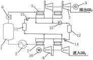
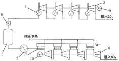
作为替代的实施方式,如图5所示,还包括燃气发电子系统,燃气发电子系统通过燃气通道与蒸汽发电子系统连通,蒸汽发电子系统的烟气排放通道上安装有二氧化碳分离装置26,二氧化碳分离装置26与压缩机组的入口端连通。燃气发电子系统中的第一发电件19与压缩机组的驱动件电连接,以为压缩机组运行提供电力。As an alternative embodiment, as shown in FIG. 5 , a gas-fired power generation subsystem is also included. The gas-fired power generation subsystem communicates with the steam power generation subsystem through a gas passage, and a carbon
具体地,燃气发电子系统包括依次串联设置的燃气轮机压缩机16、燃烧室17和燃气轮机透平机18,燃气轮机透平机18上安装有作为第一发电件19的发电机。蒸汽发电子系统包括余热锅炉20、蒸汽轮机21、冷凝器22和驱动泵24。余热锅炉20的热侧入口端与燃气通道连通,余热锅炉20的热侧出口端连通有烟气排放通道。蒸汽轮机21的入口端与余热锅炉20冷侧出口连通,冷凝器22的出口端与余热锅炉20的冷侧入口连通。驱动泵24设于冷凝器22与余热锅炉20之间,以驱动换热介质在余热锅炉20冷侧、蒸汽轮机21、冷凝器22中循环流动。在蒸汽轮机21上安装有作为第二发电件23的发电机,以对外输出电能。烟气排放通道上还安装有余热回收装置25,余热回收装置25设于二氧化碳分离装置26上游。余热回收装置25的冷侧可以连通在膨胀机组入口端的二氧化碳管路上,对二氧化碳进行预升温,在膨胀机本体的入口端不安装有外源加热器。通过对系统内的热能充分利用,减少外部能量输入,提升系统运行效率。Specifically, the gas power generation subsystem includes a
在压缩机组的入口端与膨胀机组的出口端之间连通都有二氧化碳支路,输送到压缩机组入口端的二氧化碳量大于压缩机组的工作负荷时,多余的二氧化碳通过二氧化碳支路直接排放。A carbon dioxide branch is connected between the inlet end of the compressor unit and the outlet end of the expansion unit. When the amount of carbon dioxide delivered to the inlet end of the compressor unit is greater than the working load of the compressor unit, the excess carbon dioxide is directly discharged through the carbon dioxide branch.
用电低谷储能时,来源于第一发电件19或第二发电件23多余的电能带动压缩机组压缩二氧化碳,二氧化碳来源于余热锅炉20出口的二氧化碳分离装置26,期间产生的压缩热储存在储热件中,被压缩后的高压二氧化碳经常温冷却器冷却至液态形式,后储存于作为储液件的液态二氧化碳储罐中,进而系统一部分电能转化为液态二氧化碳的内能及储热件中的热能,系统输出电能减少。当外界电能需要较大、需要释能时,液态二氧化碳储罐中的液态二氧化碳被升压泵加压后输送至余热回收装置25用于二氧化碳自身气化及提升二氧化碳自身的温度,余热回收装置25的热源为余热锅炉20排气。被余热回收装置25加热后的高压气态二氧化碳进入膨胀机组膨胀做功,各级再热器热源为储热件中储存的压缩热,进而整个耦合系统的输出电能增加,排放的二氧化碳被输送至地下储存。显然,上述实施例仅仅是为清楚地说明所作的举例,而并非对实施方式的限定。对于所属领域的普通技术人员来说,在上述说明的基础上还可以做出其它不同形式的变化或变动。这里无需也无法对所有的实施方式予以穷举。而由此所引伸出的显而易见的变化或变动仍处于本发明创造的保护范围之中。When the electricity is used to store energy in a low valley, the excess electric energy from the first
Claims (15)
Translated fromChinesePriority Applications (1)
| Application Number | Priority Date | Filing Date | Title |
|---|---|---|---|
| CN202211015654.2ACN115118017A (en) | 2022-08-24 | 2022-08-24 | Open type liquid carbon dioxide energy storage system |
Applications Claiming Priority (1)
| Application Number | Priority Date | Filing Date | Title |
|---|---|---|---|
| CN202211015654.2ACN115118017A (en) | 2022-08-24 | 2022-08-24 | Open type liquid carbon dioxide energy storage system |
Publications (1)
| Publication Number | Publication Date |
|---|---|
| CN115118017Atrue CN115118017A (en) | 2022-09-27 |
Family
ID=83335377
Family Applications (1)
| Application Number | Title | Priority Date | Filing Date |
|---|---|---|---|
| CN202211015654.2APendingCN115118017A (en) | 2022-08-24 | 2022-08-24 | Open type liquid carbon dioxide energy storage system |
Country Status (1)
| Country | Link |
|---|---|
| CN (1) | CN115118017A (en) |
Cited By (5)
| Publication number | Priority date | Publication date | Assignee | Title |
|---|---|---|---|---|
| CN116388405A (en)* | 2023-06-07 | 2023-07-04 | 势加透博(河南)能源科技有限公司 | System and method for integrating carbon dioxide seal and energy storage power generation |
| CN116658265A (en)* | 2023-04-10 | 2023-08-29 | 东方电气集团东方汽轮机有限公司 | A peak-shaving steam turbine unit energy storage and peak-shaving system |
| CN117514385A (en)* | 2023-10-20 | 2024-02-06 | 中国长江三峡集团有限公司 | A carbon dioxide energy storage and power generation system |
| CN117514388A (en)* | 2023-10-20 | 2024-02-06 | 中国长江三峡集团有限公司 | Transcritical carbon dioxide energy storage system |
| CN117578744A (en)* | 2024-01-16 | 2024-02-20 | 合肥通用机械研究院有限公司 | A compressed air energy storage power generation system and method coupled with cold recovery |
Citations (9)
| Publication number | Priority date | Publication date | Assignee | Title |
|---|---|---|---|---|
| CN105927299A (en)* | 2016-04-22 | 2016-09-07 | 石家庄新华能源环保科技股份有限公司 | Carbon dioxide energy storage and supply system |
| CN109173558A (en)* | 2018-10-19 | 2019-01-11 | 中国科学院工程热物理研究所 | A kind of low energy consumption collecting carbonic anhydride and Plugging Technology Applied and system |
| CN110159370A (en)* | 2019-05-15 | 2019-08-23 | 上海发电设备成套设计研究院有限责任公司 | A kind of coal generating system and method with carbon capture device |
| CN112392599A (en)* | 2020-11-24 | 2021-02-23 | 丁玉龙 | Power generation system and method based on liquid air |
| CN112923595A (en)* | 2021-01-28 | 2021-06-08 | 西安交通大学 | Self-condensation type compressed carbon dioxide energy storage system and method based on vortex tube |
| CN113739516A (en)* | 2021-08-17 | 2021-12-03 | 西安交通大学 | Air separation energy storage coupling oxygen-enriched combustion system and method |
| CN114382562A (en)* | 2022-01-24 | 2022-04-22 | 清华大学 | Shunt recompression pure oxygen combustion circulation system |
| CN114777419A (en)* | 2022-03-30 | 2022-07-22 | 上海发电设备成套设计研究院有限责任公司 | System and method for flue gas compression energy storage coupling carbon capture |
| CN114856738A (en)* | 2022-05-20 | 2022-08-05 | 西安交通大学 | A combined cooling, heating and power energy storage system and method based on liquid carbon dioxide storage |
- 2022
- 2022-08-24CNCN202211015654.2Apatent/CN115118017A/enactivePending
Patent Citations (9)
| Publication number | Priority date | Publication date | Assignee | Title |
|---|---|---|---|---|
| CN105927299A (en)* | 2016-04-22 | 2016-09-07 | 石家庄新华能源环保科技股份有限公司 | Carbon dioxide energy storage and supply system |
| CN109173558A (en)* | 2018-10-19 | 2019-01-11 | 中国科学院工程热物理研究所 | A kind of low energy consumption collecting carbonic anhydride and Plugging Technology Applied and system |
| CN110159370A (en)* | 2019-05-15 | 2019-08-23 | 上海发电设备成套设计研究院有限责任公司 | A kind of coal generating system and method with carbon capture device |
| CN112392599A (en)* | 2020-11-24 | 2021-02-23 | 丁玉龙 | Power generation system and method based on liquid air |
| CN112923595A (en)* | 2021-01-28 | 2021-06-08 | 西安交通大学 | Self-condensation type compressed carbon dioxide energy storage system and method based on vortex tube |
| CN113739516A (en)* | 2021-08-17 | 2021-12-03 | 西安交通大学 | Air separation energy storage coupling oxygen-enriched combustion system and method |
| CN114382562A (en)* | 2022-01-24 | 2022-04-22 | 清华大学 | Shunt recompression pure oxygen combustion circulation system |
| CN114777419A (en)* | 2022-03-30 | 2022-07-22 | 上海发电设备成套设计研究院有限责任公司 | System and method for flue gas compression energy storage coupling carbon capture |
| CN114856738A (en)* | 2022-05-20 | 2022-08-05 | 西安交通大学 | A combined cooling, heating and power energy storage system and method based on liquid carbon dioxide storage |
Non-Patent Citations (1)
| Title |
|---|
| MARCO A 等: "A novel energy storage system based on carbon dioxide unique thermodynamic properties", JOURNAL OF ENGINEERING FOR GAS TURBINES AND POWER-TRANSACTIONS OF THE ASME, 12 August 2022 (2022-08-12), pages 144* |
Cited By (7)
| Publication number | Priority date | Publication date | Assignee | Title |
|---|---|---|---|---|
| CN116658265A (en)* | 2023-04-10 | 2023-08-29 | 东方电气集团东方汽轮机有限公司 | A peak-shaving steam turbine unit energy storage and peak-shaving system |
| CN116388405A (en)* | 2023-06-07 | 2023-07-04 | 势加透博(河南)能源科技有限公司 | System and method for integrating carbon dioxide seal and energy storage power generation |
| CN116388405B (en)* | 2023-06-07 | 2023-08-29 | 势加透博(河南)能源科技有限公司 | System and method for integrating carbon dioxide seal and energy storage power generation |
| CN117514385A (en)* | 2023-10-20 | 2024-02-06 | 中国长江三峡集团有限公司 | A carbon dioxide energy storage and power generation system |
| CN117514388A (en)* | 2023-10-20 | 2024-02-06 | 中国长江三峡集团有限公司 | Transcritical carbon dioxide energy storage system |
| CN117578744A (en)* | 2024-01-16 | 2024-02-20 | 合肥通用机械研究院有限公司 | A compressed air energy storage power generation system and method coupled with cold recovery |
| CN117578744B (en)* | 2024-01-16 | 2024-03-26 | 合肥通用机械研究院有限公司 | A compressed air energy storage power generation system and method coupled with cold recovery |
Similar Documents
| Publication | Publication Date | Title |
|---|---|---|
| CN112325497B (en) | Liquefied carbon dioxide energy storage system and application thereof | |
| CN103233820B (en) | Caes and the integrated power generation system of combined cycle | |
| CN115118017A (en) | Open type liquid carbon dioxide energy storage system | |
| CN111121390B (en) | A method for using a liquefied air energy storage power generation system coupled with a steam-water system of a coal-fired generator set | |
| CN111305919A (en) | A flexible peak-shaving system and method for air energy storage in a power plant | |
| CN111121389B (en) | A method for using a deep-coupled coal-fired unit liquefied air energy storage power generation system | |
| CN109681279B (en) | Supercritical carbon dioxide power generation system and method containing liquid air energy storage | |
| US20120128463A1 (en) | System and method for managing thermal issues in one or more industrial processes | |
| CN203374333U (en) | Power generation system capable of stabilizing electricity peak-valley fluctuation | |
| CN111173719A (en) | Liquefied air energy storage system with preheating evaporator | |
| CN113090507B (en) | Combined cooling, heating and power system and method based on compressed air energy storage and organic Rankine cycle | |
| CN213807777U (en) | Coupling system of thermal power generation system and compressed air energy storage system | |
| CN115142924A (en) | Carbon dioxide energy storage system with cold accumulation device | |
| CN112412561B (en) | Coupling control method for compressed air energy storage system and thermal power plant control system | |
| CN114109547A (en) | Coal-fired power plant peak regulation system based on supercritical carbon dioxide energy storage and operation method | |
| CN114370391B (en) | A supercritical compressed air energy storage system | |
| CN114991895A (en) | Coal-fired power generating unit with coupled compressed air energy storage function and operation method thereof | |
| WO2023226666A1 (en) | Carbon dioxide energy storage system and method coupled with coal power unit | |
| CN111271143A (en) | System and method for improving electric power flexibility | |
| CN114961910A (en) | Series-parallel connection combined type compressed air energy storage device system and method | |
| CN117569881A (en) | Supercritical compressed carbon dioxide and spray packed bed fire storage coupling method and system | |
| CN119617304A (en) | Low-energy-consumption double-medium compressed air energy storage system | |
| CN115370428A (en) | Multi-energy coupling compressed air energy storage power generation system and operation method | |
| CN206256940U (en) | A kind of deep cooling liquid air energy storage systems of waste heat boosting type | |
| CN115306500B (en) | Transcritical compressed carbon dioxide energy storage system and operation method thereof |
Legal Events
| Date | Code | Title | Description |
|---|---|---|---|
| PB01 | Publication | ||
| PB01 | Publication | ||
| SE01 | Entry into force of request for substantive examination | ||
| SE01 | Entry into force of request for substantive examination |