CN115117827A - Busway and Power Distribution System - Google Patents
Busway and Power Distribution SystemDownload PDFInfo
- Publication number
- CN115117827A CN115117827ACN202210885298.3ACN202210885298ACN115117827ACN 115117827 ACN115117827 ACN 115117827ACN 202210885298 ACN202210885298 ACN 202210885298ACN 115117827 ACN115117827 ACN 115117827A
- Authority
- CN
- China
- Prior art keywords
- groove
- accommodating
- length direction
- slot
- bus duct
- Prior art date
- Legal status (The legal status is an assumption and is not a legal conclusion. Google has not performed a legal analysis and makes no representation as to the accuracy of the status listed.)
- Pending
Links
- 238000003780insertionMethods0.000claimsabstractdescription75
- 230000037431insertionEffects0.000claimsabstractdescription75
- 238000005192partitionMethods0.000claimsdescription10
- 238000009413insulationMethods0.000claimsdescription4
- 238000009434installationMethods0.000description11
- 230000005540biological transmissionEffects0.000description6
- 238000010586diagramMethods0.000description5
- 230000005611electricityEffects0.000description5
- 229910052751metalInorganic materials0.000description4
- 239000002184metalSubstances0.000description4
- 238000013461designMethods0.000description3
- RYGMFSIKBFXOCR-UHFFFAOYSA-NCopperChemical compound[Cu]RYGMFSIKBFXOCR-UHFFFAOYSA-N0.000description2
- 229910052782aluminiumInorganic materials0.000description2
- XAGFODPZIPBFFR-UHFFFAOYSA-NaluminiumChemical compound[Al]XAGFODPZIPBFFR-UHFFFAOYSA-N0.000description2
- 230000009286beneficial effectEffects0.000description2
- 239000004020conductorSubstances0.000description2
- 229910052802copperInorganic materials0.000description2
- 239000010949copperSubstances0.000description2
- 239000011810insulating materialSubstances0.000description2
- 238000004519manufacturing processMethods0.000description2
- 230000007935neutral effectEffects0.000description2
- 206010014357Electric shockDiseases0.000description1
- 230000000694effectsEffects0.000description1
- 230000017525heat dissipationEffects0.000description1
- 238000012423maintenanceMethods0.000description1
- 238000000034methodMethods0.000description1
- 238000012986modificationMethods0.000description1
- 230000004048modificationEffects0.000description1
- 238000003032molecular dockingMethods0.000description1
Images


Classifications
- H—ELECTRICITY
- H01—ELECTRIC ELEMENTS
- H01R—ELECTRICALLY-CONDUCTIVE CONNECTIONS; STRUCTURAL ASSOCIATIONS OF A PLURALITY OF MUTUALLY-INSULATED ELECTRICAL CONNECTING ELEMENTS; COUPLING DEVICES; CURRENT COLLECTORS
- H01R25/00—Coupling parts adapted for simultaneous co-operation with two or more identical counterparts, e.g. for distributing energy to two or more circuits
- H01R25/16—Rails or bus-bars provided with a plurality of discrete connecting locations for counterparts
- H01R25/161—Details
- H01R25/162—Electrical connections between or with rails or bus-bars
- H—ELECTRICITY
- H02—GENERATION; CONVERSION OR DISTRIBUTION OF ELECTRIC POWER
- H02G—INSTALLATION OF ELECTRIC CABLES OR LINES, OR OF COMBINED OPTICAL AND ELECTRIC CABLES OR LINES
- H02G5/00—Installations of bus-bars
- H02G5/06—Totally-enclosed installations, e.g. in metal casings
- H—ELECTRICITY
- H02—GENERATION; CONVERSION OR DISTRIBUTION OF ELECTRIC POWER
- H02G—INSTALLATION OF ELECTRIC CABLES OR LINES, OR OF COMBINED OPTICAL AND ELECTRIC CABLES OR LINES
- H02G5/00—Installations of bus-bars
- H02G5/06—Totally-enclosed installations, e.g. in metal casings
- H02G5/08—Connection boxes therefor
- Y—GENERAL TAGGING OF NEW TECHNOLOGICAL DEVELOPMENTS; GENERAL TAGGING OF CROSS-SECTIONAL TECHNOLOGIES SPANNING OVER SEVERAL SECTIONS OF THE IPC; TECHNICAL SUBJECTS COVERED BY FORMER USPC CROSS-REFERENCE ART COLLECTIONS [XRACs] AND DIGESTS
- Y02—TECHNOLOGIES OR APPLICATIONS FOR MITIGATION OR ADAPTATION AGAINST CLIMATE CHANGE
- Y02T—CLIMATE CHANGE MITIGATION TECHNOLOGIES RELATED TO TRANSPORTATION
- Y02T10/00—Road transport of goods or passengers
- Y02T10/60—Other road transportation technologies with climate change mitigation effect
- Y02T10/70—Energy storage systems for electromobility, e.g. batteries
- Y—GENERAL TAGGING OF NEW TECHNOLOGICAL DEVELOPMENTS; GENERAL TAGGING OF CROSS-SECTIONAL TECHNOLOGIES SPANNING OVER SEVERAL SECTIONS OF THE IPC; TECHNICAL SUBJECTS COVERED BY FORMER USPC CROSS-REFERENCE ART COLLECTIONS [XRACs] AND DIGESTS
- Y02—TECHNOLOGIES OR APPLICATIONS FOR MITIGATION OR ADAPTATION AGAINST CLIMATE CHANGE
- Y02T—CLIMATE CHANGE MITIGATION TECHNOLOGIES RELATED TO TRANSPORTATION
- Y02T10/00—Road transport of goods or passengers
- Y02T10/60—Other road transportation technologies with climate change mitigation effect
- Y02T10/7072—Electromobility specific charging systems or methods for batteries, ultracapacitors, supercapacitors or double-layer capacitors
Landscapes
- Installation Of Bus-Bars (AREA)
- Connector Housings Or Holding Contact Members (AREA)
- Buckles (AREA)
Abstract
Description
Translated fromChinese本公开要求于2022年03月17日提交的申请号为202210266566.3、发明名称为“母线插接结构、母线槽、插接头和锁止结构”的中国专利申请的优先权,其全部内容通过引用结合在本申请中。The present disclosure claims the priority of the Chinese patent application filed on March 17, 2022 with application number 202210266566.3 and titled "Busbar Plug-in Structure, Busway, Plug Connector and Locking Structure", the entire contents of which are incorporated by reference in this application.
技术领域technical field
本公开属于母线槽配电技术领域,特别涉及一种母线槽及配电系统。The present disclosure belongs to the technical field of busbar trunking power distribution, and in particular relates to a busbar trunking and a power distribution system.
背景技术Background technique
母线槽是以铜板或铝板等金属板作为导体板,以绝缘材料作为支撑,搭配金属壳体而形成的大电流输送设备。The bus duct is a large current transmission equipment formed by using a metal plate such as a copper plate or an aluminum plate as a conductor plate, supported by an insulating material, and matched with a metal shell.
在电力输送上,母线槽相对于传统的电缆,具有安装和维护方便,以及使用寿命长等突出的优点,其应用越来越广泛。In power transmission, compared with traditional cables, bus ducts have outstanding advantages such as easy installation and maintenance, and long service life, and their applications are becoming more and more extensive.
发明内容SUMMARY OF THE INVENTION
本公开实施例提供了一种母线槽及配电系统,能够实现母线槽的快速装配。所述技术方案如下:The embodiments of the present disclosure provide a busbar trunking and a power distribution system, which can realize rapid assembly of the busbar trunking. The technical solution is as follows:
一方面,本公开实施例提供了一种母线槽,所述母线槽包括:In one aspect, an embodiment of the present disclosure provides a busway, the busway comprising:
壳体,具有沿着长度方向分布的多个插接槽,且多个所述插接槽的槽口位于所述壳体的同一侧,所述插接槽的槽壁具有多个连接凸条,所述连接凸条的长度方向和所述插接槽的槽壁长度方向一致;The casing has a plurality of insertion slots distributed along the length direction, the slots of the plurality of insertion slots are located on the same side of the casing, and the groove walls of the insertion slots have a plurality of connecting protruding strips , the length direction of the connecting protruding strip is consistent with the length direction of the groove wall of the insertion slot;
绝缘支架,位于所述插接槽中,所述绝缘支架的外壁具有多个连接凹槽,所述连接凹槽的长度方向和所述插接槽的槽壁长度方向一致,所述连接凸条可移动地插接在对应的所述连接凹槽内;an insulating bracket, located in the insertion slot, the outer wall of the insulating bracket has a plurality of connection grooves, the length direction of the connection groove is consistent with the length direction of the slot wall of the insertion slot, and the connection convex strip Removably inserted in the corresponding connecting groove;
导电板,位于所述绝缘支架中,所述导电板具有暴露在所述插接槽中的接电面。A conductive plate is located in the insulating support, and the conductive plate has an electrical connection surface exposed in the insertion slot.
在本公开的一种实现方式中,多个所述连接凸条包括第一凸条,所述第一凸条位于所述插接槽的槽底;In an implementation manner of the present disclosure, a plurality of the connecting protruding strips include a first protruding strip, and the first protruding strip is located at a groove bottom of the insertion slot;
多个所述连接凹槽包括第一凹槽,所述第一凹槽的内轮廓与所述第一凸条的外轮廓相匹配;The plurality of connecting grooves include a first groove, and the inner contour of the first groove matches the outer contour of the first protruding strip;
所述第一凸条可移动地插接在所述第一凹槽内。The first protruding strip is movably inserted into the first groove.
在本公开的一种实现方式中,多个所述连接凸条包括第二凸条,所述第二凸条位于所述插接槽的槽壁侧部,所述第二凸条远离所述插接槽的槽壁一端具有第一限位台,所述第一限位台的长度方向和所述第二凸条的长度方向均与所述插接槽的槽壁长度方向一致;In an implementation of the present disclosure, a plurality of the connecting protruding strips include second protruding strips, the second protruding strips are located at the side of the groove wall of the insertion slot, and the second protruding strips are far from the One end of the slot wall of the insertion slot is provided with a first limit platform, and the length direction of the first limit platform and the length direction of the second protruding strip are both consistent with the length direction of the slot wall of the insertion slot;
多个所述连接凹槽包括第二凹槽,所述第二凹槽的内轮廓与所述第一限位台的外轮廓相匹配;The plurality of connecting grooves include second grooves, and the inner contour of the second groove matches the outer contour of the first stop;
所述第一限位台可移动地卡接在所述第二凹槽内。The first limiting platform is movably clamped in the second groove.
在本公开的一种实现方式中,多个所述连接凸条包括第三凸条,所述第三凸条位于所述插接槽的槽口,所述第三凸条远离所述插接槽的槽壁一端具有第二限位台,所述第二限位台的长度方向和所述第三凸条的长度方向均与所述插接槽的槽壁长度方向一致;In an implementation manner of the present disclosure, a plurality of the connecting protruding strips includes a third protruding strip, the third protruding strip is located at a notch of the insertion slot, and the third protruding strip is away from the insertion socket One end of the slot wall of the slot is provided with a second limit platform, and the length direction of the second limit platform and the length direction of the third protruding strip are consistent with the length direction of the slot wall of the insertion slot;
多个所述连接凹槽包括第三凹槽,所述第三凹槽的内轮廓与所述第二限位台的外轮廓相匹配;The plurality of connecting grooves include third grooves, and the inner contour of the third groove matches the outer contour of the second limiting platform;
所述第二限位台可移动地卡接在所述第三凹槽内。The second limiting platform is movably clamped in the third groove.
在本公开的一种实现方式中,所述绝缘支架的外壁具有沿自身长度方向延伸的容置通槽;In an implementation manner of the present disclosure, the outer wall of the insulating support has an accommodating through groove extending along its own length direction;
所述导电板位于所述容置通槽中,所述导电板的接电面通过所述容置通槽的槽口暴露在所述插接槽中。The conductive plate is located in the accommodating through groove, and the electrical connection surface of the conductive plate is exposed in the insertion groove through the notch of the accommodating through groove.
在本公开的一种实现方式中,所述容置通槽的槽壁具有凸止口;In an implementation manner of the present disclosure, a groove wall of the accommodating through groove has a convex stop;
所述凸止口凸出于所述容置通槽的槽壁,且所述凸止口位于所述容置通槽的槽口处;The protruding stop is protruding from the groove wall of the accommodating through slot, and the protruding stop is located at the notch of the accommodating through slot;
所述导电板的接电面具有凹止口,所述凹止口与所述凸止口插接在一起。The electrical connection surface of the conductive plate has a concave stop, and the concave stop and the convex stop are inserted together.
在本公开的一种实现方式中,所述容置通槽的槽底具有支撑凸条;In an implementation manner of the present disclosure, the groove bottom of the receiving through groove has a supporting ridge;
所述支撑凸条的长度方向和所述容置通槽的长度方向一致,所述导电板的背离所述接电面的一面与所述支撑凸条相抵,以使所述导电板与所述容置通槽的槽底相间隔。The length direction of the support protruding strip is consistent with the length direction of the accommodating through groove. The groove bottoms of the accommodating through grooves are spaced apart.
在本公开的一种实现方式中,所述容置通槽的槽口与所述插接槽的槽口之间的距离为10-20mm。In an implementation manner of the present disclosure, the distance between the notch of the accommodating through slot and the notch of the insertion slot is 10-20 mm.
在本公开的一种实现方式中,所述容置通槽包括地线容置通槽;In an implementation manner of the present disclosure, the accommodating through groove includes a ground wire accommodating through groove;
当所述母线槽为直流母线槽,所述地线容置通槽为第一尺寸,当所述母线槽为交流母线槽,所述地线容置通槽为第二尺寸,第一尺寸大于第二尺寸。When the bus duct is a DC bus duct, the ground wire accommodating through slot has a first size, and when the bus duct is an AC bus duct, the ground wire accommodating through slot has a second size, and the first size is larger than second size.
在本公开的一种实现方式中,所述壳体内具有多个隔板;In an implementation manner of the present disclosure, the housing has a plurality of partitions;
多个所述隔板相互间隔,以在所述壳体内形成多个所述插接槽,所述隔板的相对两侧均具有所述绝缘支架和所述导电板。A plurality of the partitions are spaced apart from each other to form a plurality of the insertion slots in the housing, and opposite sides of the partitions are provided with the insulating support and the conductive plate.
另一方面,本公开实施例提供了一种配电系统,包括前文所述的母线槽。On the other hand, an embodiment of the present disclosure provides a power distribution system including the aforementioned bus duct.
本公开实施例提供的技术方案带来的有益效果至少包括:The beneficial effects brought by the technical solutions provided by the embodiments of the present disclosure include at least:
壳体上具有多个插接槽,用于容置绝缘支架和导电板,并为绝缘支架提供安装基础。由于插接槽的槽壁具有多个连接凸条,相应的,绝缘支架的外壁具有多个连接凹槽,且连接凸条的长度方向和连接凹槽的长度方向均与插接槽的槽壁长度方向一致,所以将连接凸条对准连接凹槽,沿插接槽的槽壁长度将连接凸条插入相应的连接凹槽,即可实现绝缘支架在壳体内的安装,有效的提高了母线槽的装配效率。并且,导电板设置在绝缘支架内,导电板的接电面暴露在插接槽中,从而既实现了导电板与壳体之间的绝缘安装,保证了用电安全,又实现了导电板与插接箱的插接头电连接。The housing has a plurality of insertion slots for accommodating the insulating bracket and the conductive plate, and providing the installation foundation for the insulating bracket. Since the slot wall of the insertion slot has a plurality of connecting ridges, correspondingly, the outer wall of the insulating bracket has a plurality of connecting grooves, and the length direction of the connecting ridge and the length direction of the connecting groove are both the same as the slot wall of the insertion slot. The length direction is the same, so align the connecting protruding strips with the connecting grooves, and insert the connecting protruding strips into the corresponding connecting grooves along the length of the groove wall of the insertion slot, so as to realize the installation of the insulating bracket in the shell, which effectively improves the busbar. slot assembly efficiency. In addition, the conductive plate is arranged in the insulating bracket, and the electrical connection surface of the conductive plate is exposed in the insertion slot, so as to realize the insulation installation between the conductive plate and the shell, ensure the safety of electricity use, and realize the connection between the conductive plate and the shell. The plug connectors of the plug box are electrically connected.
附图说明Description of drawings
为了更清楚地说明本公开实施例中的技术方案,下面将对实施例描述中所需要使用的附图作简单地介绍,显而易见地,下面描述中的附图仅仅是本公开的一些实施例,对于本领域普通技术人员来讲,在不付出创造性劳动的前提下,还可以根据这些附图获得其他的附图。In order to illustrate the technical solutions in the embodiments of the present disclosure more clearly, the following briefly introduces the accompanying drawings used in the description of the embodiments. Obviously, the accompanying drawings in the following description are only some embodiments of the present disclosure. For those of ordinary skill in the art, other drawings can also be obtained from these drawings without creative effort.
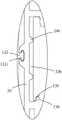
图1是本公开实施例提供的母线槽的结构示意图;1 is a schematic structural diagram of a busway provided by an embodiment of the present disclosure;
图2是本公开实施例提供的母线槽的剖视图;2 is a cross-sectional view of a busbar provided by an embodiment of the present disclosure;
图3是本公开实施例提供的图2的A部分局部放大图;3 is a partial enlarged view of part A of FIG. 2 provided by an embodiment of the present disclosure;
图4是本公开实施例提供的图2的B部分局部放大图;FIG. 4 is a partial enlarged view of part B of FIG. 2 provided by an embodiment of the present disclosure;
图5是本公开实施例提供的图2的C部分局部放大图;FIG. 5 is a partial enlarged view of part C of FIG. 2 provided by an embodiment of the present disclosure;
图6是本公开实施例提供的图2的D部分局部放大图;6 is a partial enlarged view of part D of FIG. 2 provided by an embodiment of the present disclosure;
图7是本公开实施例提供的母线槽插接示意图;7 is a schematic diagram of the insertion of a busway provided by an embodiment of the present disclosure;
图8是本公开实施例提供的配电系统的结构示意图。FIG. 8 is a schematic structural diagram of a power distribution system provided by an embodiment of the present disclosure.
图中各符号表示含义如下:The meanings of the symbols in the figure are as follows:
10、壳体;10. Shell;
110、插接槽;120、连接凸条;121、第一凸条;122、第二凸条;1221、第一限位台;123、第三凸条;1231、第二限位台;130、隔板;110, socket slot; 120, connecting ridge; 121, first ridge; 122, second ridge; 1221, first limit table; 123, third ridge; 1231, second limit table; 130 , partition;
20、绝缘支架;20. Insulation bracket;
210、连接凹槽;211、第一凹槽;212、第二凹槽;213、第三凹槽;220、容置通槽;230、凸止口;240、支撑凸条;210, connecting groove; 211, first groove; 212, second groove; 213, third groove; 220, accommodating through groove; 230, convex stop; 240, supporting convex strip;
30、导电板;30. Conductive plate;
310、接电面;320、凹止口;310, electrical connection surface; 320, concave stop;
100、母线槽;200、插接箱;2100、插接头。100, busway; 200, plug box; 2100, plug connector.
具体实施方式Detailed ways
为使本公开的目的、技术方案和优点更加清楚,下面将结合附图对本公开实施方式作进一步地详细描述。In order to make the objectives, technical solutions and advantages of the present disclosure clearer, the embodiments of the present disclosure will be further described in detail below with reference to the accompanying drawings.
本公开实施例提供了一种母线槽,该母线槽应用于配电系统中。母线槽是以铜板或铝板等金属板作为导体板,以绝缘材料作为支撑,搭配金属壳体而形成的大电流输送设备,在电力输送干线工程项目中已越来越多地代替了电缆。相匹配的,配电系统包括插接箱,插接箱也可以称为取电箱,用于插接在母线槽中,从中取电。Embodiments of the present disclosure provide a bus duct, which is used in a power distribution system. The bus duct is a high-current transmission equipment formed by using a metal plate such as a copper plate or an aluminum plate as a conductor plate, supported by an insulating material, and matched with a metal casing. It has increasingly replaced cables in power transmission trunk line projects. Correspondingly, the power distribution system includes a plug-in box, which can also be called a power-taking box, which is used for plugging into the busway and taking electricity from it.
例如,包括母线槽的配电系统可以应用在互联网数据中心(Internet DataCenter,简称IDC)中,具体应用可以是,母线槽布置在IDC的机房中,外部的配电(如市电和蓄电池等)引入到IDC机房以后,接入母线槽。插接箱插在母线槽中,从中取电,插接箱包括输电口,电缆插在插接箱的输电口上,并引向IDC机房中的各个机柜(如各个列头柜)中,为各个机柜供电。For example, the power distribution system including the busbar can be applied in the Internet Data Center (IDC), and the specific application can be that the busbar is arranged in the computer room of the IDC, and the external power distribution (such as mains and batteries, etc.) After being introduced into the IDC room, access the busway. The plug-in box is inserted into the busway, and the power is drawn from it. The plug-in box includes a power transmission port, and the cable is inserted into the power transmission port of the plug-in box and led to each cabinet (such as each column head cabinet) in the IDC room. Cabinet power supply.
下面对母线槽做进一步的介绍。The following is a further introduction to the busway.
图1为母线槽的结构示意图,参见图1,在本实施例中,母线槽包括:壳体10、绝缘支架20和导电板30。FIG. 1 is a schematic structural diagram of a busbar. Referring to FIG. 1 , in this embodiment, the busbar includes: a
图2为母线槽的剖视图,结合图2,壳体10具有沿着长度方向分布的多个插接槽110,且多个插接槽110的槽口位于壳体10的同一侧,插接槽110的槽壁具有多个连接凸条120,连接凸条120的长度方向和插接槽110的槽壁长度方向一致。绝缘支架20位于插接槽110中,绝缘支架20的外壁具有多个连接凹槽210,连接凹槽210的长度方向和插接槽110的槽壁长度方向一致,连接凸条120可移动地插接在对应的连接凹槽210内。导电板30,位于绝缘支架20中,导电板30具有暴露在插接槽110中的接电面310。FIG. 2 is a cross-sectional view of the busway. Referring to FIG. 2, the
壳体10上具有多个插接槽110,用于容置绝缘支架20和导电板30,并为绝缘支架20提供安装基础。由于插接槽110的槽壁具有多个连接凸条120,相应的,绝缘支架20的外壁具有多个连接凹槽210,且连接凸条120的长度方向和连接凹槽210的长度方向均与插接槽110的槽壁长度方向一致,所以将连接凸条120对准连接凹槽210,沿插接槽110的槽壁长度将连接凸条120插入相应的连接凹槽210,即可实现绝缘支架20在壳体10内的安装,有效的提高了母线槽的装配效率。并且,导电板30设置在绝缘支架20内,导电板30的接电面310暴露在插接槽110中,从而既实现了导电板30与壳体10之间的绝缘安装,保证了用电安全,又实现了导电板30与插接箱200的插接头2100电连接。The
在本实施例中,母线槽可以是小母线槽,小母线槽也即是传输的电流在800A以内的母线槽。当然,该母线槽也可以是大母线槽,本申请实施例对母线槽所属的具体类型不做限定。In this embodiment, the bus duct may be a small bus duct, and the small bus duct is a bus duct that transmits a current within 800A. Of course, the bus duct may also be a large bus duct, and the embodiment of the present application does not limit the specific type of the bus duct.
由前文可知,连接凸条120和连接凹槽210之间的配合,能够实现壳体10和绝缘支架20之间的快速装配,下面对连接凸条120和连接凹槽210进行介绍。As can be seen from the foregoing, the cooperation between the connecting protruding
图3为图2的A部分局部放大图,结合图3,在本实施例中,多个连接凸条120包括第一凸条121,第一凸条121位于插接槽110的槽底,多个连接凹槽210包括第一凹槽211,第一凹槽211的内轮廓与第一凸条121的外轮廓相匹配,第一凸条121可移动地插接在第一凹槽211内。FIG. 3 is a partial enlarged view of part A of FIG. 2 . With reference to FIG. 3 , in this embodiment, the plurality of connecting
在上述实现方式中,第一凸条121为多个连接凸条120中的一种类型,相应的,第一凹槽211为多个连接凹槽210中的一种类型。In the above implementation manner, the
示例性地,第一凸条121的外轮廓为圆弧形,将第一凸条121的外轮廓设计为圆弧形,既能够对绝缘支架20进行限位,又能够便于第一凸条121和第一凹槽211之间的插装。Exemplarily, the outer contour of the first
图4为图2的B部分局部放大图,结合图4,在本实施例中,多个连接凸条120包括第二凸条122,第二凸条122位于插接槽110的槽壁侧部,第二凸条122远离插接槽110的槽壁一端具有第一限位台1221,第一限位台1221的长度方向和第二凸条122的长度方向均与插接槽110的槽壁长度方向一致。多个连接凹槽210包括第二凹槽212,第二凹槽212的内轮廓与第一限位台1221的外轮廓相匹配,第一限位台1221可移动地卡接在第二凹槽212内。FIG. 4 is a partial enlarged view of part B of FIG. 2 . With reference to FIG. 4 , in this embodiment, the plurality of connecting protruding
在上述实现方式中,第二凸条122为多个连接凸条120中的一种类型,相应的,第二凹槽212为多个连接凹槽210中的一种类型。第一限位台1221位于第二凸条122远离插接槽110的槽壁的一端,使得第二凸条122和第一限位台1221之间形成一个T字形,如此一来,将第一限位台1221卡接在第二凹槽212内,使得绝缘支架20只能够沿着插接槽110的槽壁长度方向移动,而无法脱出。In the above implementation manner, the
示例性地,第二凸条122和第一限位台1221之间为一体式结构件。如此设计,不仅提高了第二凸条122和第一限位台1221之间的结构强度,还提高了第二凸条122和第一限位台1221之间的制造效率。Exemplarily, the second
图5为图2的C部分局部放大图,结合图5,在本实施例中,多个连接凸条120包括第三凸条123,第三凸条123位于插接槽110的槽口,第三凸条123远离插接槽110的槽壁一端具有第二限位台1231,第二限位台1231的长度方向和第三凸条123的长度方向均与插接槽110的槽壁长度方向一致。多个连接凹槽210包括第三凹槽213,第三凹槽213的内轮廓与第二限位台1231的外轮廓相匹配,第二限位台1231可移动地卡接在第三凹槽213内。FIG. 5 is a partial enlarged view of part C of FIG. 2 . With reference to FIG. 5 , in this embodiment, the plurality of connecting protruding
在上述实现方式中,第三凸条123为多个连接凸条120中的一种类型,相应的,第三凹槽213为多个连接凹槽210中的一种类型。第二限位台1231位于第三凸条123远离插接槽110的槽壁的一端,使得第三凸条123和第二限位台1231之间形成一个P字形,如此一来,将第二限位台1231卡接在第三凹槽213内,使得绝缘支架20只能够沿着插接槽110的槽壁长度方向移动,而无法脱出。In the above implementation manner, the
示例性地,第三凸条123和第二限位台1231之间为一体式结构件。如此设计,不仅提高了第三凸条123和第二限位台1231之间的结构强度,还提高了第三凸条123和第二限位台1231之间的制造效率。Exemplarily, between the third
在本实施例中,第二凸条122和第三凸条123起到主要的卡接装配作用,能够有效的避免绝缘支架20从壳体10上脱出。第一凸条121则起到辅助限位作用,不仅能够有效的避免绝缘支架20出现不必要的摆动,还能够便于对接装配。由第一凸条121、第二凸条122和第三凸条123组成的多个连接凸条120,与由第二凹槽212、第二凹槽212和第三凹槽213组成的多个连接凹槽210相互配合,能够实现绝缘支架20与壳体10之间的快速、稳固装配。In this embodiment, the second protruding strips 122 and the third protruding strips 123 play a major role in snap-fitting and assembling, which can effectively prevent the insulating
再次参见图2,在本实施例中,绝缘支架20的外壁具有沿自身长度方向延伸的容置通槽220,导电板30位于容置通槽220中,导电板30的接电面310通过容置通槽220210的槽口暴露在插接槽110中。Referring to FIG. 2 again, in this embodiment, the outer wall of the insulating
在上述实现方式中,绝缘支架20具有容置通槽220,容置通槽220用于为导电板30提供安装空间,导电板30插接在容置通槽220内,并将接电面310暴露在插接槽110中,从而既实现了导电板30与壳体10之间的绝缘安装,保证了用电安全,又不会影响到导电板30与插接箱200的插接头2100之间的电连接。In the above implementation manner, the insulating
示例性地,容置通槽220的槽壁具有凸止口230,凸止口230凸出于容置通槽220的槽壁,且凸止口230位于容置通槽220的槽口处。导电板30的接电面310具有凹止口320,凹止口320与凸止口230插接在一起。Exemplarily, the groove wall of the accommodating through
在上述实现方式中,凸止口230和凹止口320之间能够相互配合,使得导电板30被卡接在容置通槽220内,从而实现导电板30和绝缘支架20之间的稳固安装。In the above-mentioned implementation manner, the
图6为图2的D部分局部放大图,结合图6,在本实施例中,容置通槽220的槽底具有支撑凸条240,支撑凸条240的长度方向和容置通槽220的长度方向一致,导电板30的背离接电面310的一面与支撑凸条240相抵,以使导电板30与容置通槽220的槽底相间隔。FIG. 6 is a partial enlarged view of part D of FIG. 2 . With reference to FIG. 6 , in this embodiment, the groove bottom of the accommodating through
由于导电板30与支撑凸条240相抵,所以导电板30不直接与容置通槽220的槽底接触,使得导电板30与容置通槽220的槽底之间具有间隙,利用该间隙,能够有效的提高母线槽的散热效果。Since the
示例性地,容置通槽220的槽口与插接槽110的槽口之间的距离d为10-20mm。Exemplarily, the distance d between the notch of the receiving through
在上述实现方式中,若有人员的手指非常的纤细,其能够插入插接槽110内。但是由于容置通槽220的槽口与插接槽110的槽口之间的距离d为10-20mm,所以使得人员插入插接槽110内的手指,无法通过容置通槽220的槽口触碰到导电板30,从而降低了触电的风险,提高了用电安全。In the above implementation manner, if a person's finger is very slender, it can be inserted into the
在本实施例中,母线槽能够应用于不同制式的配电系统中,例如三相五线制的配电系统、三相四线制的配电系统。若配电系统为三相五线制,那么母线槽包括五个导电板30,五个导电板30分别对应三根相线、一根零线、一根地线。相应的,母线槽包括五个绝缘支架20,五个绝缘支架20上均具有用于容置导电板30的容置通槽220。若配电系统为三相四线制,那么母线槽包括四个导电板30,四个导电板30分别对应三根相线和一根零线,或者是三根相线和一根地线。相应的,母线槽包括四个绝缘支架20,四个绝缘支架20上均具有用于容置导电板30的容置通槽220。其中,用于容置地线导电板的容置通槽220为地线容置通槽。当母线槽为直流母线槽,地线容置通槽为第一尺寸,当母线槽为交流母线槽,地线容置通槽为第二尺寸,第一尺寸大于第二尺寸。通过合理的设计地线容置通槽的尺寸,能够使得母线槽适用于不同的配电系统,提高了母线槽的适用性。In this embodiment, the busbar can be applied to power distribution systems of different standards, such as a three-phase five-wire power distribution system and a three-phase four-wire power distribution system. If the power distribution system is a three-phase five-wire system, the busway includes five
需要说明的是,地线容置通槽的尺寸,能够通过调整支撑凸条240的尺寸来实现相应的调整。例如,将支撑凸条240的尺寸设计的较大,地线容置通槽的尺寸就会相应的较小,将支撑凸条240的尺寸设计的较小,地线容置通槽的尺寸就会相应的较大。It should be noted that, the size of the ground wire accommodating through groove can be adjusted accordingly by adjusting the size of the
在本实施例中,壳体10内具有多个隔板130,多个隔板130相互间隔,以在壳体10内形成多个插接槽110,隔板130的相对两侧均具有绝缘支架20和导电板30。In this embodiment, the
在上述实现方式中,一个插接槽110内具有两个导电板30,两个导电板30的接电面310相对间隔布置,能够分别与插接箱200的插接头2100接触,从而实现“一槽两极”,使得母线槽的结构更为紧凑。In the above implementation manner, there are two
在本实施例中,位于插接槽110内的两个绝缘支架20内均具有导电板30,且两个导电板30的极性互不相同。In this embodiment, the two insulating
在上述实现方式中,由于插接槽110中具有两个导电板30,且两个导电板30的极性互不相同,所以当一个插接头2100插接至一个插接槽110内后,即可使得该插接头2100分别与两种极性实现电连接(参见图7)。如此一来,有效的减少了插接槽110的数量,使得母线槽的结构更为简单,有利于实现母线槽的小型化设计。In the above implementation manner, since there are two
除此之外,在插接箱200的插接头2100沿着插接槽110的深度方向,插接至插接槽110中之后,插接头2100就能够与导电板30的接电面310接触,不再需要其他操作,即可实现母线槽与插接箱200之间的快捷电连接。In addition, after the
在一种应用中,插接槽110的槽口所处的一侧为母线槽的插接侧,母线槽的背对插接侧的一侧为安装侧,母线槽的安装侧可以安装在IDC机房的顶部,母线槽的插接槽110朝向IDC机房的地面,技术人员可以手持插接箱200,将插接箱200的插接头2100插入至母线槽中,例如,将插接头2100一一插入至母线槽的插接槽110中,从而实现插接箱200在母线槽中的取电。In one application, the side where the slot of the
图8为本公开实施例提供的一种配电系统的结构示意图,参见图8,在本实施例中,该配电系统包括图1-7所示的母线槽100和插接箱200。FIG. 8 is a schematic structural diagram of a power distribution system according to an embodiment of the present disclosure. Referring to FIG. 8 , in this embodiment, the power distribution system includes the
由于该配电系统包括图1-7所示的母线槽100,所以该配电系统具有图1-7所示的母线槽100的全部有益效果,在此不再赘述。Since the power distribution system includes the
除非另作定义,此处使用的技术术语或者科学术语应当为本公开所属领域内具有一般技能的人士所理解的通常意义。本公开专利申请说明书以及权利要求书中使用的“第一”、“第二”、“第三”以及类似的词语并不表示任何顺序、数量或者重要性,而只是用来区分不同的组成部分。同样,“一个”或者“一”等类似词语也不表示数量限制,而是表示存在至少一个。“包括”或者“包含”等类似的词语意指出现在“包括”或者“包含”前面的元件或者物件涵盖出现在“包括”或者“包含”后面列举的元件或者物件及其等同,并不排除其他元件或者物件。“连接”或者“相连”等类似的词语并非限定于物理的或者机械的连接,而是可以包括电性的连接,不管是直接的还是间接的。“上”、“下”、“左”、“右”等仅用于表示相对位置关系,当被描述对象的绝对位置改变后,则所述相对位置关系也可能相应地改变。Unless otherwise defined, technical or scientific terms used herein shall have the ordinary meaning as understood by one of ordinary skill in the art to which this disclosure belongs. The terms "first," "second," "third," and similar terms used in the description and claims of the presently disclosed patent application do not denote any order, quantity, or importance, but are merely used to distinguish the different components . Likewise, "a" or "an" and the like do not denote a quantitative limitation, but rather denote the presence of at least one. Words like "including" or "comprising" mean that the elements or items listed before "including" or "including" cover the elements or items listed after "including" or "including" and their equivalents, and do not exclude other component or object. Words like "connected" or "connected" are not limited to physical or mechanical connections, but may include electrical connections, whether direct or indirect. "Up", "Down", "Left", "Right", etc. are only used to indicate relative positional relationship, and when the absolute position of the described object changes, the relative positional relationship may also change accordingly.
以上所述仅为本公开的可选实施例,并不用以限制本公开,凡在本公开的精神和原则之内,所作的任何修改、等同替换、改进等,均应包含在本公开的保护范围之内。The above are only optional embodiments of the present disclosure, and are not intended to limit the present disclosure. Any modifications, equivalent replacements, improvements, etc. made within the spirit and principles of the present disclosure shall be included in the protection of the present disclosure. within the range.
Claims (11)
Translated fromChineseApplications Claiming Priority (2)
| Application Number | Priority Date | Filing Date | Title |
|---|---|---|---|
| CN2022102665663 | 2022-03-17 | ||
| CN202210266566 | 2022-03-17 |
Publications (1)
| Publication Number | Publication Date |
|---|---|
| CN115117827Atrue CN115117827A (en) | 2022-09-27 |
Family
ID=83162532
Family Applications (13)
| Application Number | Title | Priority Date | Filing Date |
|---|---|---|---|
| CN202210729981.8APendingCN115051186A (en) | 2022-03-17 | 2022-06-24 | Get electric plug, jack box and generating line transmission of electricity system |
| CN202210729967.8APendingCN115051185A (en) | 2022-03-17 | 2022-06-24 | Plug box and bus system |
| CN202210788002.6APendingCN115085124A (en) | 2022-03-17 | 2022-07-04 | Clamping mechanism, busway and power distribution system |
| CN202221780278.1UActiveCN217881991U (en) | 2022-03-17 | 2022-07-05 | Electricity taking insertion sheet, plug box and bus system |
| CN202221805571.9UActiveCN217983786U (en) | 2022-03-17 | 2022-07-11 | Bus plug-in structure and power distribution system |
| CN202221797149.3UActiveCN217823590U (en) | 2022-03-17 | 2022-07-11 | Bus plugging structure and power distribution system |
| CN202210813453.0APendingCN115579696A (en) | 2022-03-17 | 2022-07-11 | Bus duct and power distribution system |
| CN202221840573.1UActiveCN217823398U (en) | 2022-03-17 | 2022-07-14 | Insulation protection plate, plug, power taking plug, plug box and bus transmission system |
| CN202221917505.0UActiveCN217823536U (en) | 2022-03-17 | 2022-07-21 | Bus plugging structure and power distribution system |
| CN202221917150.5UActiveCN217956266U (en) | 2022-03-17 | 2022-07-21 | Locking structure, plug-in box and power distribution system |
| CN202210863771.8APendingCN115149478A (en) | 2022-03-17 | 2022-07-21 | Connectors and Power Distribution Systems |
| CN202221932818.3UActiveCN217823361U (en) | 2022-03-17 | 2022-07-22 | Bus duct and power distribution system |
| CN202210885298.3APendingCN115117827A (en) | 2022-03-17 | 2022-07-26 | Busway and Power Distribution System |
Family Applications Before (12)
| Application Number | Title | Priority Date | Filing Date |
|---|---|---|---|
| CN202210729981.8APendingCN115051186A (en) | 2022-03-17 | 2022-06-24 | Get electric plug, jack box and generating line transmission of electricity system |
| CN202210729967.8APendingCN115051185A (en) | 2022-03-17 | 2022-06-24 | Plug box and bus system |
| CN202210788002.6APendingCN115085124A (en) | 2022-03-17 | 2022-07-04 | Clamping mechanism, busway and power distribution system |
| CN202221780278.1UActiveCN217881991U (en) | 2022-03-17 | 2022-07-05 | Electricity taking insertion sheet, plug box and bus system |
| CN202221805571.9UActiveCN217983786U (en) | 2022-03-17 | 2022-07-11 | Bus plug-in structure and power distribution system |
| CN202221797149.3UActiveCN217823590U (en) | 2022-03-17 | 2022-07-11 | Bus plugging structure and power distribution system |
| CN202210813453.0APendingCN115579696A (en) | 2022-03-17 | 2022-07-11 | Bus duct and power distribution system |
| CN202221840573.1UActiveCN217823398U (en) | 2022-03-17 | 2022-07-14 | Insulation protection plate, plug, power taking plug, plug box and bus transmission system |
| CN202221917505.0UActiveCN217823536U (en) | 2022-03-17 | 2022-07-21 | Bus plugging structure and power distribution system |
| CN202221917150.5UActiveCN217956266U (en) | 2022-03-17 | 2022-07-21 | Locking structure, plug-in box and power distribution system |
| CN202210863771.8APendingCN115149478A (en) | 2022-03-17 | 2022-07-21 | Connectors and Power Distribution Systems |
| CN202221932818.3UActiveCN217823361U (en) | 2022-03-17 | 2022-07-22 | Bus duct and power distribution system |
Country Status (2)
| Country | Link |
|---|---|
| CN (13) | CN115051186A (en) |
| WO (1) | WO2023174051A1 (en) |
Cited By (1)
| Publication number | Priority date | Publication date | Assignee | Title |
|---|---|---|---|---|
| CN115864268A (en)* | 2022-12-06 | 2023-03-28 | 山东德恒电气有限公司 | Female row of wing section aluminum alloy and switch board |
Families Citing this family (9)
| Publication number | Priority date | Publication date | Assignee | Title |
|---|---|---|---|---|
| CN115051186A (en)* | 2022-03-17 | 2022-09-13 | 公牛集团股份有限公司 | Get electric plug, jack box and generating line transmission of electricity system |
| CN117060304B (en)* | 2023-08-15 | 2024-11-26 | 惠州市克莱沃电子有限公司 | Detachable integrated power distribution system |
| CN117060303B (en)* | 2023-08-15 | 2024-10-01 | 惠州市克莱沃电子有限公司 | Power distribution device capable of taking power step by step |
| CN117060153B (en)* | 2023-08-15 | 2024-10-01 | 惠州市克莱沃电子有限公司 | Plug-in power supply device |
| CN116979314B (en)* | 2023-09-22 | 2023-12-19 | 常州施勤线束有限公司 | Anti-loosening joint device for automobile electricity taking device |
| CN118693573B (en)* | 2024-07-02 | 2024-12-27 | 扬州森源电力科技有限公司 | An anti-drop busbar connector assembly with a positioning structure |
| CN119362049B (en)* | 2024-12-27 | 2025-04-11 | 四川信连电子科技有限公司 | An output terminal |
| CN119542787B (en)* | 2025-01-23 | 2025-04-11 | 浙江桥架母线有限公司 | A busbar conductive connection device |
| CN119891056A (en)* | 2025-03-31 | 2025-04-25 | 上海恒嘉电气有限公司 | Power transmission bus and power distribution system thereof |
Citations (5)
| Publication number | Priority date | Publication date | Assignee | Title |
|---|---|---|---|---|
| US7744386B1 (en)* | 2009-11-02 | 2010-06-29 | Lighting Services Inc. | High amperage busway system |
| US9407079B1 (en)* | 2015-04-16 | 2016-08-02 | Eaton Corporation | Busway systems and related assemblies and methods |
| CN106992482A (en)* | 2017-03-08 | 2017-07-28 | 突破电气(天津)有限公司 | Bus duct, bus-bar system and connection method |
| CN107181080A (en)* | 2017-05-19 | 2017-09-19 | 深圳市海德森科技股份有限公司 | Power taking plug |
| CN213341573U (en)* | 2020-09-29 | 2021-06-01 | 镇江加勒智慧电力科技股份有限公司 | Insulating bus duct |
Family Cites Families (27)
| Publication number | Priority date | Publication date | Assignee | Title |
|---|---|---|---|---|
| JPH05124485A (en)* | 1991-10-31 | 1993-05-21 | Takata Kk | Pretensioner with extension preventing mechanism |
| US6039584A (en)* | 1998-11-09 | 2000-03-21 | Universal Electric Corporation | Electrical power distribution system |
| JP4401506B2 (en)* | 1999-12-27 | 2010-01-20 | 共同カイテック株式会社 | Bus duct connection device |
| US20040144827A1 (en)* | 2003-01-27 | 2004-07-29 | Ted Fox | Uni-directional wire advancing and holding device |
| CN201562757U (en)* | 2009-11-20 | 2010-08-25 | 江苏威腾母线有限公司 | bus connector |
| CN101950936B (en)* | 2010-08-25 | 2012-07-25 | 镇江西门子母线有限公司 | Dense plug-pull bus system |
| CN201901170U (en)* | 2010-12-20 | 2011-07-20 | 赛博实业有限公司 | Stroller Seat Belt Adjuster |
| DE102012005330A1 (en)* | 2012-03-19 | 2013-09-19 | Trw Automotive Gmbh | Belt retractor and method for locking a belt retractor |
| CN202712607U (en)* | 2012-08-03 | 2013-01-30 | 泰科电子(上海)有限公司 | Plug connector and electric connector assembly |
| CN102820560B (en)* | 2012-08-08 | 2015-10-07 | 江苏万奇电器集团有限公司 | The single-phase monolithic transition conductor docking jockey of a kind of bus duct joint and method |
| CN102842779B (en)* | 2012-09-19 | 2014-11-05 | 江苏万奇电器集团有限公司 | Spacing slot insulated plug component for bus duct plug-in box |
| CN105932622B (en)* | 2016-06-27 | 2018-11-23 | 江苏华鹏电力设备股份有限公司 | Dense insulated bus duct |
| CN206650398U (en)* | 2016-11-29 | 2017-11-17 | 湖北睿能电气有限公司 | Bus-bar connecting box apparatus |
| CN108173208A (en)* | 2016-12-07 | 2018-06-15 | 镇江凯勒电力科技有限公司 | A kind of bus duct |
| CN106953189A (en)* | 2017-03-01 | 2017-07-14 | 华为技术有限公司 | A busway device and data center |
| CN206712167U (en)* | 2017-04-20 | 2017-12-05 | 珠海市跳跃自动化科技有限公司 | A kind of bus duct copper bar socket |
| GB201804300D0 (en)* | 2018-03-16 | 2018-05-02 | Turnbull Lee | Remotely actuated strap adjusting mechanism |
| CN108711803A (en)* | 2018-06-15 | 2018-10-26 | 江苏德泽智能电气科技有限公司 | A kind of socket insulation system for bus duct joint device position |
| CN111153045A (en)* | 2018-11-08 | 2020-05-15 | 梁炳基 | Ribbon capable of being used in two-sided and two-way mode |
| CN209805363U (en)* | 2019-04-28 | 2019-12-17 | 北京国电恒嘉科技产业集团有限公司 | Air bus duct |
| CN112072372B (en)* | 2020-08-12 | 2021-11-12 | 突破电气(天津)有限公司 | Bus type PDU |
| CN213585079U (en)* | 2020-09-18 | 2021-06-29 | 河南远明电力科技有限公司 | A plug-in mechanism for a busway plug-in box |
| CN214227757U (en)* | 2020-11-04 | 2021-09-17 | 江苏中远电气设备有限公司 | Connecting structure for fixing bus duct |
| CN113097817B (en)* | 2021-03-26 | 2023-05-30 | 江苏亿能电气有限公司 | Get electric plug |
| CN113285263B (en)* | 2021-07-26 | 2021-11-05 | 突破电气(天津)有限公司 | Plug for taking electricity |
| CN215771624U (en)* | 2021-07-30 | 2022-02-08 | 公牛集团股份有限公司 | Get electric terminal, jack box and get electric system |
| CN115051186A (en)* | 2022-03-17 | 2022-09-13 | 公牛集团股份有限公司 | Get electric plug, jack box and generating line transmission of electricity system |
- 2022
- 2022-06-24CNCN202210729981.8Apatent/CN115051186A/enactivePending
- 2022-06-24CNCN202210729967.8Apatent/CN115051185A/enactivePending
- 2022-07-04CNCN202210788002.6Apatent/CN115085124A/enactivePending
- 2022-07-05CNCN202221780278.1Upatent/CN217881991U/enactiveActive
- 2022-07-11CNCN202221805571.9Upatent/CN217983786U/enactiveActive
- 2022-07-11CNCN202221797149.3Upatent/CN217823590U/enactiveActive
- 2022-07-11CNCN202210813453.0Apatent/CN115579696A/enactivePending
- 2022-07-14CNCN202221840573.1Upatent/CN217823398U/enactiveActive
- 2022-07-21CNCN202221917505.0Upatent/CN217823536U/enactiveActive
- 2022-07-21CNCN202221917150.5Upatent/CN217956266U/enactiveActive
- 2022-07-21CNCN202210863771.8Apatent/CN115149478A/enactivePending
- 2022-07-22CNCN202221932818.3Upatent/CN217823361U/enactiveActive
- 2022-07-26CNCN202210885298.3Apatent/CN115117827A/enactivePending
- 2023
- 2023-02-28WOPCT/CN2023/078877patent/WO2023174051A1/ennot_activeCeased
Patent Citations (5)
| Publication number | Priority date | Publication date | Assignee | Title |
|---|---|---|---|---|
| US7744386B1 (en)* | 2009-11-02 | 2010-06-29 | Lighting Services Inc. | High amperage busway system |
| US9407079B1 (en)* | 2015-04-16 | 2016-08-02 | Eaton Corporation | Busway systems and related assemblies and methods |
| CN106992482A (en)* | 2017-03-08 | 2017-07-28 | 突破电气(天津)有限公司 | Bus duct, bus-bar system and connection method |
| CN107181080A (en)* | 2017-05-19 | 2017-09-19 | 深圳市海德森科技股份有限公司 | Power taking plug |
| CN213341573U (en)* | 2020-09-29 | 2021-06-01 | 镇江加勒智慧电力科技股份有限公司 | Insulating bus duct |
Cited By (1)
| Publication number | Priority date | Publication date | Assignee | Title |
|---|---|---|---|---|
| CN115864268A (en)* | 2022-12-06 | 2023-03-28 | 山东德恒电气有限公司 | Female row of wing section aluminum alloy and switch board |
Also Published As
| Publication number | Publication date |
|---|---|
| CN217983786U (en) | 2022-12-06 |
| CN217823590U (en) | 2022-11-15 |
| CN217956266U (en) | 2022-12-02 |
| CN115051185A (en) | 2022-09-13 |
| WO2023174051A1 (en) | 2023-09-21 |
| CN115051186A (en) | 2022-09-13 |
| CN115085124A (en) | 2022-09-20 |
| CN217823536U (en) | 2022-11-15 |
| CN115149478A (en) | 2022-10-04 |
| CN217823398U (en) | 2022-11-15 |
| CN217881991U (en) | 2022-11-22 |
| CN217823361U (en) | 2022-11-15 |
| CN115579696A (en) | 2023-01-06 |
Similar Documents
| Publication | Publication Date | Title |
|---|---|---|
| CN115117827A (en) | Busway and Power Distribution System | |
| US10770869B2 (en) | AC power adapter and power distribution system employing same | |
| CN106450980B (en) | Bus duct and get electric plug | |
| CN106992482B (en) | Bus duct, bus-bar system and connection method | |
| CN106410617A (en) | Bus duct power supply system | |
| CN106953189A (en) | A busway device and data center | |
| US11217971B2 (en) | AC power adapter and power distribution system employing same | |
| CN108963487B (en) | A copper busbar connection structure | |
| CN204760962U (en) | Power supply system is female to be arranged and insulating bush guard plate system | |
| CN217848892U (en) | Wire arranging buckle, bus duct and power distribution system | |
| CN211126186U (en) | An insulating backing plate and a busbar flexible connector using the insulating backing plate | |
| CN216850468U (en) | Wall socket | |
| CN212257916U (en) | Two-sided joinable's waterproof dirt-proof socket of dustproof of rail mounted | |
| CN111585100B (en) | Socket with improved structure | |
| CN111064034B (en) | Insulating pad and busbar flexible connector using the insulating pad | |
| CN208255291U (en) | A junction box body and a pluggable electric energy meter junction box | |
| CN220122286U (en) | Three-phase busbar | |
| CN219717449U (en) | Power rails, adapters and rail sockets | |
| CN222215113U (en) | Bus duct housing and bus duct | |
| CN222928068U (en) | Rail type bus duct and hot plug system | |
| CN106684623B (en) | A socket and socket | |
| CN111293458A (en) | Modular combined socket and modular power supply assembly | |
| CN220138783U (en) | Socket | |
| CN217824155U (en) | Enclosure, busway and power distribution system | |
| CN218602876U (en) | Server power connector |
Legal Events
| Date | Code | Title | Description |
|---|---|---|---|
| PB01 | Publication | ||
| PB01 | Publication | ||
| SE01 | Entry into force of request for substantive examination | ||
| SE01 | Entry into force of request for substantive examination |