CN115113396A - Display device including combiner with asymmetric magnification - Google Patents
Display device including combiner with asymmetric magnificationDownload PDFInfo
- Publication number
- CN115113396A CN115113396ACN202210026644.2ACN202210026644ACN115113396ACN 115113396 ACN115113396 ACN 115113396ACN 202210026644 ACN202210026644 ACN 202210026644ACN 115113396 ACN115113396 ACN 115113396A
- Authority
- CN
- China
- Prior art keywords
- display device
- virtual image
- combiner
- light
- magnification
- Prior art date
- Legal status (The legal status is an assumption and is not a legal conclusion. Google has not performed a legal analysis and makes no representation as to the accuracy of the status listed.)
- Pending
Links
Images


Classifications
- G—PHYSICS
- G02—OPTICS
- G02B—OPTICAL ELEMENTS, SYSTEMS OR APPARATUS
- G02B27/00—Optical systems or apparatus not provided for by any of the groups G02B1/00 - G02B26/00, G02B30/00
- G02B27/01—Head-up displays
- G02B27/017—Head mounted
- G02B27/0172—Head mounted characterised by optical features
- G—PHYSICS
- G02—OPTICS
- G02B—OPTICAL ELEMENTS, SYSTEMS OR APPARATUS
- G02B27/00—Optical systems or apparatus not provided for by any of the groups G02B1/00 - G02B26/00, G02B30/00
- G02B27/42—Diffraction optics, i.e. systems including a diffractive element being designed for providing a diffractive effect
- G02B27/4205—Diffraction optics, i.e. systems including a diffractive element being designed for providing a diffractive effect having a diffractive optical element [DOE] contributing to image formation, e.g. whereby modulation transfer function MTF or optical aberrations are relevant
- G02B27/4227—Diffraction optics, i.e. systems including a diffractive element being designed for providing a diffractive effect having a diffractive optical element [DOE] contributing to image formation, e.g. whereby modulation transfer function MTF or optical aberrations are relevant in image scanning systems
- G—PHYSICS
- G02—OPTICS
- G02B—OPTICAL ELEMENTS, SYSTEMS OR APPARATUS
- G02B6/00—Light guides; Structural details of arrangements comprising light guides and other optical elements, e.g. couplings
- G02B6/0001—Light guides; Structural details of arrangements comprising light guides and other optical elements, e.g. couplings specially adapted for lighting devices or systems
- G02B6/0011—Light guides; Structural details of arrangements comprising light guides and other optical elements, e.g. couplings specially adapted for lighting devices or systems the light guides being planar or of plate-like form
- G02B6/0033—Means for improving the coupling-out of light from the light guide
- G02B6/0035—Means for improving the coupling-out of light from the light guide provided on the surface of the light guide or in the bulk of it
- G02B6/004—Scattering dots or dot-like elements, e.g. microbeads, scattering particles, nanoparticles
- G02B6/0043—Scattering dots or dot-like elements, e.g. microbeads, scattering particles, nanoparticles provided on the surface of the light guide
- G—PHYSICS
- G02—OPTICS
- G02B—OPTICAL ELEMENTS, SYSTEMS OR APPARATUS
- G02B6/00—Light guides; Structural details of arrangements comprising light guides and other optical elements, e.g. couplings
- G02B6/24—Coupling light guides
- G02B6/26—Optical coupling means
- G02B6/34—Optical coupling means utilising prism or grating
- G—PHYSICS
- G02—OPTICS
- G02B—OPTICAL ELEMENTS, SYSTEMS OR APPARATUS
- G02B27/00—Optical systems or apparatus not provided for by any of the groups G02B1/00 - G02B26/00, G02B30/00
- G02B27/01—Head-up displays
- G02B27/0101—Head-up displays characterised by optical features
- G02B2027/013—Head-up displays characterised by optical features comprising a combiner of particular shape, e.g. curvature
- G—PHYSICS
- G02—OPTICS
- G02B—OPTICAL ELEMENTS, SYSTEMS OR APPARATUS
- G02B27/00—Optical systems or apparatus not provided for by any of the groups G02B1/00 - G02B26/00, G02B30/00
- G02B27/01—Head-up displays
- G02B27/017—Head mounted
- G02B2027/0178—Eyeglass type
Landscapes
- Physics & Mathematics (AREA)
- General Physics & Mathematics (AREA)
- Optics & Photonics (AREA)
- Diffracting Gratings Or Hologram Optical Elements (AREA)
Abstract
Description
Translated fromChinese技术领域technical field
本公开涉及包括具有非对称放大率的组合器的显示装置,更具体地,涉及能够通过使用具有非对称放大率的组合器来增大虚拟图像的高宽比的显示装置。The present disclosure relates to a display device including a combiner with asymmetric magnification, and more particularly, to a display device capable of increasing the aspect ratio of a virtual image by using the combiner with asymmetric magnification.
背景技术Background technique
提供虚拟现实(VR)的头戴式显示器已经在市面上有售并广泛用于娱乐行业。与此同时,头戴式显示器已经发展成适用于医疗领域、教育领域和其他行业的领域。Head mounted displays that provide virtual reality (VR) are already commercially available and widely used in the entertainment industry. At the same time, head-mounted displays have grown into applications in the medical field, education, and other industries.
作为VR显示器的高级形式的增强现实(AR)显示器是将现实世界与VR相结合并能够实现现实与VR之间的交互的图像设备。现实与VR之间的交互基于提供关于现实情景的实时信息的功能,并且现实的效果通过将虚拟对象或信息叠加在现实世界环境上而进一步增加。Augmented reality (AR) displays, which are an advanced form of VR displays, are image devices that combine the real world with VR and enable interaction between reality and VR. The interaction between reality and VR is based on the ability to provide real-time information about real-world situations, and the effect of reality is further increased by superimposing virtual objects or information on the real-world environment.
发明内容SUMMARY OF THE INVENTION
提供了包括具有非对称放大率的组合器的显示装置。A display device including a combiner with asymmetric magnification is provided.
提供了能够通过使用具有非对称放大率的组合器来增大虚拟图像的高宽比的显示装置。A display device capable of increasing the aspect ratio of a virtual image by using a combiner with an asymmetric magnification is provided.
提供了增强现实(AR)显示装置,其配置为提供根据西涅玛斯科普式宽银幕(CinemaScope)标准具有大高宽比的虚拟图像。An augmented reality (AR) display device is provided that is configured to provide virtual images having a high aspect ratio according to the CinemaScope standard.
额外的方面将部分地在以下描述中阐述,并将部分地自该描述明显,或者可以通过本公开的所呈现的实施方式的实践而获悉。Additional aspects will be set forth in part in the following description, and in part will be apparent from this description, or may be learned by practice of the presented embodiments of the present disclosure.
根据本公开的一方面,提供了一种显示装置,其包括:成像器件,配置为形成虚拟图像;以及组合器,配置为将虚拟图像与对应于外部环境的光混合,并向观看者提供彼此混合的虚拟图像和光,其中组合器包括弯曲表面,该弯曲表面基于第一方向上的第一放大率和垂直于第一方向的第二方向上的第二放大率来改变虚拟图像的尺寸,第二放大率小于第一放大率。According to an aspect of the present disclosure, there is provided a display apparatus including: an imaging device configured to form a virtual image; and a combiner configured to mix the virtual image with light corresponding to an external environment and provide a viewer with each other A mixed virtual image and light, wherein the combiner includes a curved surface that changes the size of the virtual image based on a first magnification in a first direction and a second magnification in a second direction perpendicular to the first direction, the first The second magnification is smaller than the first magnification.
组合器包括配置为传输虚拟图像的透明波导,弯曲表面形成在透明波导的表面上。The combiner includes a transparent waveguide configured to transmit a virtual image, and a curved surface is formed on the surface of the transparent waveguide.
透明波导包括:布置为彼此面对的第一表面和第二表面;以及布置在第一表面和第二表面之间的第三表面和第四表面,其中第三表面和第四表面彼此面对,其中弯曲表面包括形成在第一表面上的第一弯曲表面和形成在第二表面上的第二弯曲表面,以及其中第三表面和第四表面彼此平行地布置从而不具有屈光力。The transparent waveguide includes: first and second surfaces arranged to face each other; and third and fourth surfaces arranged between the first and second surfaces, wherein the third and fourth surfaces face each other , wherein the curved surface includes a first curved surface formed on the first surface and a second curved surface formed on the second surface, and wherein the third surface and the fourth surface are arranged parallel to each other so as to have no refractive power.
第一弯曲表面和第二弯曲表面形成:在第一方向上,处于沿着光轴的第一位置处的第一主平面和处于沿着光轴的第二位置处的焦平面;以及在第二方向上,处于沿着光轴的不同于第一位置的第三位置处的第二主平面和处于沿着光轴的第二位置处的所述焦平面。The first curved surface and the second curved surface form: in the first direction, a first principal plane at a first position along the optical axis and a focal plane at a second position along the optical axis; and In two directions, a second principal plane at a third position along the optical axis different from the first position and the focal plane at a second position along the optical axis.
第一弯曲表面和第二弯曲表面中的每个在第一方向上具有比组合器在第一方向上的总宽度小的宽度。Each of the first curved surface and the second curved surface has a width in the first direction that is less than a total width of the combiner in the first direction.
成像器件被布置为朝向第一表面提供虚拟图像,并且第一表面被布置为使得穿过第一表面的虚拟图像传播到透明波导中。The imaging device is arranged to provide a virtual image towards the first surface, and the first surface is arranged such that the virtual image passing through the first surface propagates into the transparent waveguide.
成像器件被布置为面对第三表面的部分区域,并且第一表面被布置为反射穿过第三表面的虚拟图像。The imaging device is arranged to face a partial area of the third surface, and the first surface is arranged to reflect a virtual image passing through the third surface.
成像器件被布置为面对第四表面的部分区域,并且第一表面被布置为反射穿过第四表面的虚拟图像。The imaging device is arranged to face a partial area of the fourth surface, and the first surface is arranged to reflect a virtual image passing through the fourth surface.
组合器还包括透光板,该透光板包括:第五表面,与第二表面接触并具有与形成在第二表面上的第二弯曲表面互补的形状;从第三表面延伸的第六表面;以及从第四表面延伸的第七表面。The combiner also includes a light-transmitting plate including: a fifth surface in contact with the second surface and having a shape complementary to a second curved surface formed on the second surface; a sixth surface extending from the third surface ; and a seventh surface extending from the fourth surface.
组合器还包括在第二表面上的半透半反涂层。The combiner also includes a transflective coating on the second surface.
透明波导包括:布置为彼此面对的第一表面和第二表面;以及布置在第一表面和第二表面之间的第三表面和第四表面,其中第三表面和第四表面彼此面对,以及其中第一表面是倾斜的平坦表面,弯曲表面形成在第二表面上,第三表面和第四表面彼此平行地布置从而不具有屈光力。The transparent waveguide includes: first and second surfaces arranged to face each other; and third and fourth surfaces arranged between the first and second surfaces, wherein the third and fourth surfaces face each other , and wherein the first surface is an inclined flat surface, a curved surface is formed on the second surface, and the third surface and the fourth surface are arranged parallel to each other so as to have no refractive power.
组合器还包括透光板,该透光板包括:第五表面,与弯曲表面接触并具有与弯曲表面互补的形状;从第三表面延伸的第六表面;以及从第四表面延伸的第七表面。The combiner also includes a light-transmitting plate comprising: a fifth surface in contact with the curved surface and having a shape complementary to the curved surface; a sixth surface extending from the third surface; and a seventh surface extending from the fourth surface surface.
成像器件被布置成朝向第一表面提供虚拟图像,并且第一表面被布置为使得穿过第一表面的虚拟图像传播到透明波导中。The imaging device is arranged to provide a virtual image towards the first surface, and the first surface is arranged such that the virtual image passing through the first surface propagates into the transparent waveguide.
成像器件被布置为面对第三表面的部分区域,并且第一表面被布置为反射穿过第三表面的虚拟图像。The imaging device is arranged to face a partial area of the third surface, and the first surface is arranged to reflect a virtual image passing through the third surface.
显示装置还包括在成像器件和第三表面之间的投影光学系统,其中弯曲表面和投影光学系统形成:在第一方向上,处于沿着光轴的第一位置处的第一主平面和处于沿着光轴的第二位置处的焦平面;以及在第二方向上,处于沿着光轴的不同于第一位置的第三位置处的第二主平面和处于沿着光轴的第二位置处的所述焦平面。The display device also includes a projection optical system between the imaging device and the third surface, wherein the curved surface and the projection optical system form: in the first direction, the first principal plane at the first position along the optical axis and the a focal plane at a second location along the optical axis; and in the second direction, a second principal plane at a third location along the optical axis different from the first location and a second principal plane along the optical axis the focal plane at the location.
透明波导包括:布置为彼此面对的第一表面和第二表面;以及布置在第一表面和第二表面之间的第三表面和第四表面,其中第三表面和第四表面彼此面对,其中弯曲表面形成在第一表面上,第三表面和第四表面彼此平行地布置从而不具有屈光力,成像器件被布置为朝向第一表面提供虚拟图像。The transparent waveguide includes: first and second surfaces arranged to face each other; and third and fourth surfaces arranged between the first and second surfaces, wherein the third and fourth surfaces face each other , wherein the curved surface is formed on the first surface, the third surface and the fourth surface are arranged parallel to each other so as to have no refractive power, and the imaging device is arranged to provide a virtual image towards the first surface.
组合器还包括衍射图案,该衍射图案布置在第四表面的部分区域中以朝向第三表面反射虚拟图像。The combiner also includes a diffraction pattern arranged in a partial area of the fourth surface to reflect the virtual image towards the third surface.
衍射图案包括第一表面和第二表面,该第一表面在垂直于第一表面的方向上反射倾斜地入射在第一表面上的对应于虚拟图像的光,该第二表面使垂直入射在第二表面上的对应于外部环境的光穿过。The diffraction pattern includes a first surface that reflects light corresponding to the virtual image obliquely incident on the first surface in a direction perpendicular to the first surface, and the second surface causes the light to be perpendicularly incident on the first surface. Light on the two surfaces corresponding to the external environment passes through.
衍射图案包括全息光学元件、衍射光学元件或超表面。Diffractive patterns include holographic optical elements, diffractive optical elements or metasurfaces.
成像器件被布置为朝向弯曲表面提供虚拟图像,并且显示装置还包括在成像器件和弯曲表面之间的投影光学系统。The imaging device is arranged to provide a virtual image towards the curved surface, and the display device further comprises a projection optical system between the imaging device and the curved surface.
组合器还包括在弯曲表面上的半透半反涂层。The combiner also includes a transflective coating on the curved surface.
组合器还包括支撑半透半反涂层的透光板。The combiner also includes a light-transmitting plate supporting the transflective coating.
根据本公开的另一方面,提供了一种显示装置,其包括:成像器件,配置为形成虚拟图像;以及组合器,配置为将虚拟图像与对应于外部环境的光混合,并向观看者提供彼此混合的虚拟图像和光,其中组合器包括:衍射图案,包括第一表面和第二表面,该第一表面在垂直于第一表面的方向上反射倾斜地入射在第一表面上的对应于虚拟图像的光,该第二表面使垂直入射在第二表面上的对应于外部环境的光穿过;以及投影光学系统,在成像器件和衍射图案之间,其中衍射图案和投影光学系统基于第一方向上的第一放大率和垂直于第一方向的第二方向上的第二放大率来改变虚拟图像的尺寸,第二放大率小于第一放大率。According to another aspect of the present disclosure, there is provided a display apparatus including: an imaging device configured to form a virtual image; and a combiner configured to mix the virtual image with light corresponding to an external environment and provide a viewer with The virtual image and light mixed with each other, wherein the combiner includes: a diffraction pattern including a first surface and a second surface, the first surface reflecting in a direction perpendicular to the first surface obliquely incident on the first surface corresponding to the virtual light of the image, the second surface passing light corresponding to the external environment normally incident on the second surface; and a projection optical system between the imaging device and the diffraction pattern, wherein the diffraction pattern and the projection optical system are based on the first A first magnification in the direction and a second magnification in a second direction perpendicular to the first direction to change the size of the virtual image, the second magnification being smaller than the first magnification.
衍射图案和投影光学系统:在第一方向上形成处于沿着光轴的第一位置处的主平面和处于沿着光轴的第二位置处的焦平面;以及在第二方向上形成处于沿着光轴的不同于第一位置的第三位置处的主平面和处于沿着光轴的第二位置处的焦平面。A diffraction pattern and a projection optical system: a principal plane at a first position along the optical axis and a focal plane at a second position along the optical axis are formed in a first direction; and a second direction is formed at a position along the optical axis A principal plane of the optical axis at a third location different from the first location and a focal plane at a second location along the optical axis.
组合器还包括支撑衍射图案的透光板。The combiner also includes a light-transmitting plate supporting the diffractive pattern.
根据本公开的另一方面,提供了一种显示装置,其包括配置为形成虚拟图像的成像器件和组合器,该组合器配置为:基于第一方向上的第一放大率和垂直于第一方向的第二方向上的第二放大率来改变虚拟图像的高宽比;通过将改变后的虚拟图像与对应于外部环境的光组合来形成增强图像;向观看者提供增强图像,其中第二放大率不同于第一放大率。According to another aspect of the present disclosure, there is provided a display device including an imaging device configured to form a virtual image and a combiner configured to: based on a first magnification in a first direction and perpendicular to a first changing the aspect ratio of the virtual image by a second magnification in a second direction of the direction; forming an enhanced image by combining the changed virtual image with light corresponding to the external environment; providing the viewer with the enhanced image, wherein the second The magnification is different from the first magnification.
组合器包括改变虚拟图像的高宽比的弯曲表面。The combiner includes a curved surface that changes the aspect ratio of the virtual image.
组合器包括改变虚拟图像的高宽比的衍射图案。The combiner includes a diffraction pattern that changes the aspect ratio of the virtual image.
附图说明Description of drawings
本公开的某些实施方式的以上及其他方面、特征和优点将由以下结合附图的描述更加明显,附图中:The above and other aspects, features and advantages of certain embodiments of the present disclosure will be more apparent from the following description taken in conjunction with the accompanying drawings, in which:
图1是示意性示出根据一示例实施方式的显示装置的构造的剖视图;FIG. 1 is a cross-sectional view schematically showing a configuration of a display device according to an example embodiment;
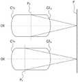
图2是示意性示出根据一示例实施方式的组合器的示例结构的前视图;2 is a front view schematically illustrating an example structure of a combiner according to an example embodiment;
图3是示出光学系统的主平面和焦平面的示例视图,该主平面和焦平面等效于图2所示的组合器的弯曲表面;FIG. 3 is an example view showing the principal and focal planes of the optical system, which principal and focal planes are equivalent to the curved surfaces of the combiner shown in FIG. 2;
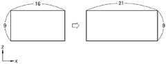
图4是示出通过图2所示的组合器来增大虚拟图像的高宽比的示例的视图;Fig. 4 is a view showing an example of increasing the aspect ratio of a virtual image by the combiner shown in Fig. 2;
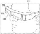
图5是示出采用根据一示例实施方式的显示装置的电子设备的示例的视图;FIG. 5 is a view illustrating an example of an electronic device employing a display device according to an example embodiment;
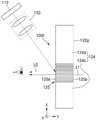
图6是示意性示出根据另一示例实施方式的组合器的示例结构的剖视图;6 is a cross-sectional view schematically illustrating an example structure of a combiner according to another example embodiment;
图7是示意性示出根据另一示例实施方式的显示装置的构造的剖视图;7 is a cross-sectional view schematically showing a configuration of a display device according to another example embodiment;
图8是示意性示出根据另一示例实施方式的显示装置的构造的剖视图;8 is a cross-sectional view schematically showing a configuration of a display device according to another example embodiment;
图9是示意性示出根据另一示例实施方式的显示装置的构造的剖视图;9 is a cross-sectional view schematically showing a configuration of a display device according to another example embodiment;
图10是示意性示出根据另一示例实施方式的显示装置的构造的剖视图;10 is a cross-sectional view schematically showing a configuration of a display device according to another example embodiment;
图11是示意性示出根据另一示例实施方式的显示装置的构造的剖视图;11 is a cross-sectional view schematically showing a configuration of a display device according to another example embodiment;
图12是示意性示出根据另一示例实施方式的显示装置的构造的剖视图;以及12 is a cross-sectional view schematically showing a configuration of a display device according to another example embodiment; and
图13是示意性示出根据另一示例实施方式的显示装置的构造的剖视图。FIG. 13 is a cross-sectional view schematically showing the configuration of a display device according to another example embodiment.
具体实施方式Detailed ways
现在将详细参照实施方式,其示例在附图中示出,其中,相同的附图标记始终指代相同的元件。就此而言,示例实施方式可以具有不同的形式并且不应被解释为限于在此阐述的描述。因此,下面通过参照附图仅描述示例实施方式以解释方面。如这里所使用的,术语“和/或”包括一个或更多个相关所列举项目的任何和所有组合。诸如“中的至少一个”的表述当在一列元素之后时,修饰整列元素,而不修饰该列中的个别元素。Reference will now be made in detail to the embodiments, examples of which are illustrated in the accompanying drawings, wherein like reference numerals refer to the like elements throughout. In this regard, example embodiments may take different forms and should not be construed as limited to the descriptions set forth herein. Accordingly, example embodiments are merely described below to explain aspects by referring to the figures. As used herein, the term "and/or" includes any and all combinations of one or more of the associated listed items. Expressions such as "at least one of," when following a list of elements, modify the entire list of elements and do not modify individual elements in the list.
在下文中,将参照附图描述包括具有非对称放大率的组合器的显示装置。在附图中,相同的附图标记指代相同的元件,并且为了图示的清楚,元件的尺寸可能被夸大。此外,这里描述的实施方式仅出于说明的目的,并且可以由此进行各种修改。Hereinafter, a display device including a combiner having an asymmetric magnification will be described with reference to the accompanying drawings. In the drawings, the same reference numerals refer to the same elements, and the dimensions of the elements may be exaggerated for clarity of illustration. Furthermore, the embodiments described herein are for illustrative purposes only and various modifications may be made therefrom.
在以下描述中,当一元件被称为“在”另一元件“之上”或“在”另一元件“上”时,它可以在与该另一元件接触的同时直接在该另一元件上,或者可以在该另一元件之上而不与该另一元件接触。单数形式的术语可以包括复数形式,除非另有说明。还将理解,这里使用的术语“包括”和/或“包含”指明所陈述的特征或元件的存在,但不排除一个或更多个其他特征或元件的存在或添加。In the following description, when an element is referred to as being "on" another element or "on" another element, it can be directly on the other element while in contact with the other element on, or may be on, the other element without contacting the other element. Terms in the singular may include the plural unless stated otherwise. It will also be understood that the terms "comprising" and/or "comprising" as used herein indicate the presence of stated features or elements, but do not exclude the presence or addition of one or more other features or elements.
用定冠词或指示代词提及的元件可以被解释为一个该元件或多个该元件,即使它具有单数形式。方法的操作可以按适当的顺序执行,除非在顺序方面明确描述或相反描述,并且方法的操作不限于其陈述的顺序。An element referred to with a definite article or demonstrative pronoun may be construed as one or more of the element, even if it has a singular form. The operations of the method may be performed in a suitable order unless explicitly described in terms of order or otherwise, and the operations of the method are not limited to the order in which they are presented.
在本公开中,诸如“单元”或“模块”的术语可以用于表示具有至少一个功能或操作并以硬件、软件或硬件和软件的组合来实现的单元。In the present disclosure, terms such as 'unit' or 'module' may be used to denote a unit having at least one function or operation and implemented in hardware, software, or a combination of hardware and software.
此外,附图中所描绘的元件之间的线路连接或连接构件以举例的方式来表示功能连接和/或物理或电路连接,在实际应用中,它们可以用各种附加的功能连接、物理连接或电路连接来替换或体现。In addition, the line connections or connecting members between the elements depicted in the drawings represent functional connections and/or physical or circuit connections by way of example, and in practical applications, they may be connected with various additional functional connections, physical connections or circuit connections to replace or embody.
示例或示例术语在此仅用于描述技术思想,并且不应出于限制的目的被考虑,除非由权利要求限定。Examples or example terms are used herein only to describe technical ideas and should not be considered for the purpose of limitation unless defined by the claims.
图1是示意性示出根据一示例实施方式的显示装置10的构造的剖视图。参照图1,该示例实施方式的显示装置100可以包括配置为形成虚拟图像的成像器件110、以及组合器120,该组合器120配置为将虚拟图像与包含外部景观的光混合并将该混合物提供给观看者。根据一示例实施方式,组合器120被配置为将虚拟图像与包含周围环境的光混合,并将该混合物提供给观看者。此外,显示装置100还可以包括用于封装成像器件110的壳体130、驱动电路、电源、附加光学系统等。壳体130也可以具有将成像器件110固定到组合器120的功能。FIG. 1 is a cross-sectional view schematically showing the configuration of a display device 10 according to an example embodiment. 1 , the
成像器件110通过根据关于虚拟图像的图像信息调制光来形成虚拟图像,并将产生的虚拟图像提供给观看者。由成像器件110形成的虚拟图像可以是例如分别提供给观看者的左眼和右眼的立体图像、全息图像、光场图像或积分摄影(IP)图像,并且可以包括多视图图像或超级多视图图像。此外,由成像器件110形成的虚拟图像可以是但不限于一般的二维图像。The
成像器件110可以包括例如硅基液晶(LCoS)器件、液晶显示(LCD)器件、有机发光二极管(OLED)显示器件或数字微镜器件(DMD)。此外,成像器件110可以包括诸如微LED显示器件或量子点(QD)LED显示器件的下一代显示器件。当成像器件110是诸如OLED显示器件或微LED显示器件的自发射式显示器件时,成像器件110可以仅包括一个显示面板。然而,当成像器件110是诸如LCoS器件或LCD器件的非发射式显示器件时,成像器件110可以进一步包括配置为提供照明光的光源和配置为调节照明光的路径的光学系统。The
组合器120不仅可以将包含由成像器件110形成的虚拟图像的光L0输出到观看者的眼睛,而且也可以将包含在观看者前方的外部景观的光L1输出到观看者的眼睛。例如,组合器120可以将包含虚拟图像的光L0朝向观看者的眼睛反射,并且可以将包含外部景观的光L1朝向观看者的眼睛透射。The
根据一示例实施方式,来自外部的光L1不是来自显示在单独的显示面板上的人工图像,而是包含存在于观看者前方的实际前景。因此,观看者可以同时感知由成像器件110人工产生的虚拟图像和实际前景。因此,显示装置100可以用作透视型显示器。此外,就此而言,示例实施方式的显示装置100可以用于实现增强现实(AR)或混合现实(MR)。例如,示例实施方式的显示装置100可以是眼镜型、护目镜型或头戴型近眼AR显示装置。According to an example embodiment, the light L1 from the outside is not from an artificial image displayed on a separate display panel, but contains the actual foreground existing in front of the viewer. Therefore, the viewer can perceive the virtual image artificially generated by the
此外,组合器120可以通过将由成像器件110形成的虚拟图像的尺寸增大为在第一方向(即,x方向)上比在垂直于第一方向的第二方向(即z方向)上更大来提供根据西涅玛斯科普式宽银幕标准具有宽视角的虚拟图像,并且可以基本上没有失真地透射包含外部景观的光L1。为此,组合器120可以包括具有非对称放大率并布置在包含虚拟图像的光L0的光路上的光学元件、以及布置在包含外部景观的光L1的路径上的透明平板。In addition, the
根据一示例实施方式,组合器120可以包括配置为引导虚拟图像的透明波导121。透明波导121可以包括多个表面,并且具有自由形状的弯曲表面可以形成在所述多个表面中的至少一个上。如图1所示,透明波导121可以包括布置为在第二方向(z方向)上彼此面对的第一表面S1和第二表面S2、以及布置在第一表面S1和第二表面S2之间并在垂直于第一方向(x方向)和第二方向(z方向)的第三方向(y方向)上彼此面对的第三表面S3和第四表面S4。弯曲表面可以包括形成在第一表面S1上的第一弯曲表面和形成在第二表面S2上的第二弯曲表面。第三表面S3和第四表面S4可以彼此平行,因此可以不具有屈光力。根据一示例实施方式,包含虚拟图像的光L0可以通过形成在第一表面S1上的第一弯曲表面和形成在第二表面S2上的第二弯曲表面聚焦在观看者的眼睛上。因此,观看者可以以宽视角看到虚拟图像。According to an example embodiment, the
成像器件110可以被布置为将包含虚拟图像的光L0提供给透明波导121的第一表面S1。此外,壳体130可以覆盖透明波导121的第一表面S1。成像器件110可以被固定,使得成像器件110可以在壳体130中面对透明波导121的第一表面S1。第一表面S1可以倾斜,使得包含虚拟图像并已穿过第一表面S1的光L0可以倾斜地传播到透明波导121中。例如,第一表面S1的中心轴线可以相对于第三表面S3和第四表面S4倾斜。在这种情况下,如图1所示,包含虚拟图像的光L0可以在透明波导121内部倾斜地入射在第三表面S3和第四表面S4上。The
在包含虚拟图像的光L0穿过第一表面S1进入透明波导121的内部之后,包含虚拟图像的光L0在被第三表面S3和第四表面S4全反射的同时,在透明波导121中沿负z方向传播。然后,包含虚拟图像的光L0被第二表面S2沿负y方向反射,并穿过第三表面S3入射在观看者的眼睛上。这里,负y方向和负z方向可以指与图1所示的坐标中的箭头所指示的方向相反的方向。第二表面S2可以倾斜,使得从第二表面S2反射的光可以基本上在垂直于第三表面S3的方向上入射在第三表面S3上。例如,第二表面S2的中心轴线可以相对于第三表面S3和第四表面S4倾斜。After the light L0 containing the virtual image enters the inside of the
此外,组合器120还可以包括透光板122,其中透光板122可以包括与透明波导121的第二表面S2接触并具有与形成在第二表面S2上的第二弯曲表面互补的形状的表面、以及分别从第三表面S3和第四表面S4连续延伸的表面。因此,透光板122可以与透明波导121共用第二表面S2、第三表面S3和第四表面S4。包含外部景观的光线L1可以在负y方向上入射在第四表面S4上,然后可以依次通过第二表面S2和第三表面S3入射在观看者的眼睛上。In addition, the
半透半反涂层可以布置在第二表面S2上以反射包含虚拟图像的光L0并透射包含外部景观的光L1。半透半反涂层可以仅反射一部分入射光并透射其余的入射光。在这种情况下,包含虚拟图像的光L0的一部分可以被第二表面S2上的半透半反涂层朝向观看者的眼睛反射,包含外部景观的光L1的一部分可以穿过第二表面S2上的半透半反涂层朝向观看者的眼睛。当包含由成像器件110形成的虚拟图像的光L0是偏振光时,半透半反涂层可以反射具有特定偏振分量的光并透射具有不同偏振分量的光。例如,当包含虚拟图像的光L0具有第一偏振分量时,半透半反涂层可以反射具有第一偏振分量的光并透射具有与第一偏振分量垂直的第二偏振分量的光。A transflective coating may be arranged on the second surface S2 to reflect the light L0 containing the virtual image and transmit the light L1 containing the external landscape. Transflective coatings can reflect only a portion of incident light and transmit the rest. In this case, a portion of the light L0 containing the virtual image may be reflected by the transflective coating on the second surface S2 towards the viewer's eyes, and a portion of the light L1 containing the external landscape may pass through the second surface S2 The transflective coating on it faces the viewer's eyes. When the light L0 containing the virtual image formed by the
图2是示意性示出根据一示例实施方式的组合器120的示例结构的前视图。参照图2,当透明波导121和透光板122彼此接合时,组合器120可以具有与眼镜镜片的形状类似的整体形状。在这种情况下,第一弯曲表面C1可以仅形成在第一表面S1的部分区域中,该部分区域是相对于包含虚拟图像的光L0的光学有效区域,第二弯曲表面C2可以仅形成在第二表面S2的部分区域中,该部分区域是关于包含虚拟图像的光L0的光学有效区域。换言之,第一弯曲表面C1和第二弯曲表面C2可以在包含虚拟图像的光L0所穿过的区域中形成在第一表面S1和第二表面S2上。第一表面S1和第二表面S2可以在x方向上延伸,其中第一弯曲表面C1可以在x方向上形成在第一表面S1的部分区域中,第二弯曲表面C2可以在x方向上形成在第二表面S2的部分区域中。因此,第一弯曲表面C1在x方向上的宽度W和第二弯曲表面C2在x方向上的宽度W可以小于组合器120在x方向上的总宽度WT。FIG. 2 is a front view schematically illustrating an example structure of the
包含虚拟图像并离开成像器件110的光L0可以仅在其中形成第一弯曲表面C1的区域中入射在第一表面S1上。此外,包含虚拟图像的光L0可以仅在其中形成第二弯曲表面C2的区域中入射在第二表面S2上。因此,将包含虚拟图像的光L0朝向观看者反射的半透半反涂层123可以不形成在整个第二表面S2上,而是可以仅形成在第二弯曲表面C2上。The light L0 containing the virtual image and exiting the
到达观看者眼睛的虚拟图像的尺寸和高宽比可以由第一弯曲表面C1和第二弯曲表面C2的几何形状确定。第一弯曲表面C1和第二弯曲表面C2可以具有不对称的放大率,以通过增大水平方向即x方向上的视角来提供根据西涅玛斯科普式宽银幕标准具有宽视角的虚拟图像。换言之,第一弯曲表面C1和第二弯曲表面C2可以具有不对称的形状,使得虚拟图像的尺寸可以在水平方向即x方向上以第一放大率来调节并在垂直方向上即在z方向上以第二放大率来调节,其中第二放大率小于第一放大率。根据一示例实施方式,第二放大率可以不同于第一放大率。The size and aspect ratio of the virtual image reaching the viewer's eyes may be determined by the geometry of the first curved surface C1 and the second curved surface C2. The first curved surface C1 and the second curved surface C2 may have an asymmetric magnification to provide a virtual image with a wide viewing angle according to the Sinemaskopian widescreen standard by increasing the viewing angle in the horizontal direction, ie, the x-direction. In other words, the first curved surface C1 and the second curved surface C2 may have asymmetric shapes, so that the size of the virtual image can be adjusted in the horizontal direction, ie, the x-direction, with the first magnification and in the vertical direction, ie, the z-direction Adjusted at a second magnification, wherein the second magnification is smaller than the first magnification. According to an example embodiment, the second magnification may be different from the first magnification.
图3是示出光学系统的主平面和焦平面的示例视图,该主平面和焦平面等效于图2所示的组合器120的第一弯曲表面C1和第二弯曲表面C2。在图1和图2所示的组合器120中,第一弯曲表面C1和第二弯曲表面C2是倾斜的,并且第一弯曲表面C1的光轴和第二弯曲表面C2的光轴彼此不重合,以便将包含虚拟图像的光L0与包含外部景观的光L1组合。然而,可以设置具有弯曲表面的等效光学系统,这些弯曲表面在对于包含虚拟图像的光L0用作第一弯曲表面C1和第二弯曲表面C2的光学等效物的同时,沿着公共光轴彼此面对。在下文中,为了易于描述,等效光学系统的弯曲表面将被描述为组合器120的第一弯曲表面C1和第二弯曲表面C2。FIG. 3 is an example view showing the principal plane and focal plane of the optical system, which are equivalent to the first curved surface C1 and the second curved surface C2 of the
参照图3,第一弯曲表面C1和第二弯曲表面C2中的每个可以在x方向和z方向上具有不同的弯曲形状。换言之,第一弯曲表面C1的x方向弯曲分量C1x可以具有与第一弯曲表面C1的z方向弯曲分量C1z的形状不同的形状,第二弯曲表面C2的x方向弯曲分量C2x可以具有与第二弯曲表面C2的z方向弯曲分量C2z的形状不同的形状。这里,x方向弯曲分量C1x和C2x分别是指沿着包含光轴OX的平面当中的平行于x方向且垂直于z方向的平面截取的第一弯曲表面C1的截面和第二弯曲表面C2的截面,并且x方向弯曲分量C1x和C2x中的每个在x方向上折射入射光。此外,z向弯曲分量C1z和C2z分别是指沿着包含光轴OX的平面当中的平行于z方向且垂直于x方向的平面截取的第一弯曲表面C1的截面和第二弯曲表面C2的截面,并且z方向弯曲分量C1z和C2z中的每个在z方向上折射入射光。Referring to FIG. 3 , each of the first curved surface C1 and the second curved surface C2 may have different curved shapes in the x-direction and the z-direction. In other words, the x-direction curvature component C1x of the first curved surface C1 may have a shape different from that of the z-direction curvature component C1z of the first curved surface C1, and the x-direction curvature component C2x of the second curved surface C2 may have a different shape from that of the second curved surface C2. A shape in which the shape of the z-direction curvature component C2z of the surface C2 is different. Here, the x-direction curvature components C1x and C2x respectively refer to a cross-section of the first curved surface C1 and a cross-section of the second curved surface C2 taken along a plane parallel to the x-direction and perpendicular to the z-direction among the planes containing the optical axis OX , and each of the x-direction bending components C1x and C2x refracts incident light in the x-direction. Further, the z-direction curvature components C1z and C2z respectively refer to a cross-section of the first curved surface C1 and a cross-section of the second curved surface C2 taken along a plane parallel to the z-direction and perpendicular to the x-direction among the planes containing the optical axis OX , and each of the z-direction bending components C1z and C2z refracts incident light in the z-direction.
因此,x方向上的第一放大率可以由第一弯曲表面C1的x方向弯曲分量C1x的形状和第二弯曲表面C2的x方向弯曲分量C2x的形状确定,z方向上的第二放大率可以由第一弯曲表面C1的z方向弯曲分量C1z和第二弯曲表面C2的z方向弯曲分量C2z的形状确定。一般而言,光学系统的放大率可以由光学系统的有效焦距确定。然而,当光学系统的焦平面的位置在x方向和z方向上不同时,观看者可以清楚地看到虚拟图像的位置在x方向和z方向上不同。Therefore, the first magnification in the x-direction may be determined by the shape of the x-direction curvature component C1x of the first curved surface C1 and the shape of the x-direction curvature component C2x of the second curved surface C2, and the second magnification in the z-direction may be It is determined by the shapes of the z-direction curvature component C1z of the first curved surface C1 and the z-direction curvature component C2z of the second curved surface C2. In general, the magnification of an optical system can be determined by the effective focal length of the optical system. However, when the positions of the focal plane of the optical system are different in the x and z directions, the viewer can clearly see that the positions of the virtual images are different in the x and z directions.
根据一示例实施方式,第一弯曲表面C1和第二弯曲表面C2被提供为使得主平面的位置在x方向和z方向上不同。术语“主平面”是指假想折射平面,入射在透镜上的平行光线在该假想折射平面处表现为开始折射。如图3所示,x方向上的主平面Px的位置和z方向上的主平面Pz的位置可以沿着光轴OX彼此不同。然而,焦平面P在x方向上的位置和焦平面P在z方向上的位置可以沿着光轴OX相同。在这种情况下,有效焦距即放大率可以在x方向和z方向上不同,并且虚拟图像在x方向上的像平面可以与虚拟图像在z方向上的像平面重合。主平面Px的位置和焦平面P在x方向上的位置可以由x方向弯曲分量C1x和C2x的形状确定,主平面Pz的位置和焦平面P在z方向上的位置可以由z方向弯曲分量C1z和C2z的形状确定。According to an example embodiment, the first curved surface C1 and the second curved surface C2 are provided such that the positions of the main planes are different in the x-direction and the z-direction. The term "principal plane" refers to the imaginary plane of refraction at which parallel rays incident on the lens appear to begin refraction. As shown in FIG. 3 , the position of the main plane Px in the x direction and the position of the main plane Pz in the z direction may be different from each other along the optical axis OX. However, the position of the focal plane P in the x direction and the position of the focal plane P in the z direction may be the same along the optical axis OX. In this case, the effective focal length, or magnification, may be different in the x and z directions, and the image plane of the virtual image in the x direction may coincide with the image plane of the virtual image in the z direction. The position of the main plane Px and the position of the focal plane P in the x direction can be determined by the shapes of the x-direction curvature components C1x and C2x, and the position of the main plane Pz and the focal plane P in the z direction can be determined by the z-direction curvature component C1z and the shape of C2z is determined.
如上所述,通过使用在x方向和z方向上具有不同截面形状以具有在x方向和z方向上处于不同位置的主平面Px和Pz以及在x方向和z方向上处于相同位置的焦平面P的第一弯曲表面C1和第二弯曲表面C2,组合器120可以增大虚拟图像的高宽比并增大虚拟图像在x方向上的视角。例如,图4是示出通过图2所示的组合器120增大虚拟图像的高宽比的示例的视图。参照图4,当成像器件110形成具有例如16:9的高宽比的虚拟图像时,可以通过组合器120向观看者显示根据西涅玛斯科普式宽银幕标准具有21:9的高宽比的虚拟图像。成像器件110可以通过考虑虚拟图像将在x方向上被放大的程度来形成在x方向上压缩的虚拟图像。然后,可以向观看者显示具有正常高宽比的虚拟图像。尽管图4示出了组合器120将虚拟图像的高宽比从16:9改变到21:9,但这仅是非限制性示例。可以根据显示装置100的设计不同地选择由成像器件110形成的虚拟图像的高宽比和通过组合器120向观看者显示的虚拟图像的高宽比。As described above, by using different cross-sectional shapes in the x and z directions to have the principal planes Px and Pz at different positions in the x and z directions and the focal plane P at the same position in the x and z directions The first curved surface C1 and the second curved surface C2 of the
根据一示例实施方式,代替在组合器120上形成多个复杂的弯曲表面,彼此不对称的第一弯曲表面C1和第二弯曲表面C2仅形成在组合器120的彼此面对的第一表面S1和第二表面S2上,从而减小组合器120的厚度。例如,即使当组合器120具有约3mm至约6mm的小厚度时,第一弯曲表面C1和第二弯曲表面C2也可以形成在组合器120上。因此,可以使用具有小厚度的薄组合器120来提供具有宽视角和大高宽比的虚拟图像。此外,还可以减小包括组合器120的显示装置100的尺寸和重量。According to an example embodiment, instead of forming a plurality of complex curved surfaces on the
如上所述,显示装置100可以用于实现AR或MR。例如,图5是示出电子设备200采用根据一示例实施方式的显示装置100的示例的视图。参照图5,例如,电子设备200可以是可穿戴设备、头戴式显示器(HMD)、眼镜型显示器或护目镜型显示器。电子设备200可以与智能电话结合操作。电子设备200可以是能够提供VR或虚拟图像和真实外部图像的混合的头戴型、眼镜型或护目镜型的虚拟现实(VR)、AR或MR显示器。As described above, the
特别地,当电子设备200是眼镜型近眼显示器或护目镜型近眼显示器时,组合器120可以位于观看者眼睛的前方以用作眼镜的屏幕,并且壳体130可以用作支撑组合器120的眼镜架。壳体130可以延伸到眼镜的镜腿231。包括图像处理处理器等的控制电路可以布置在镜腿231中。电子设备200可以包括配置为分别布置在观看者的左眼和右眼前方的两个显示装置100,或者可以仅包括配置为布置在观看者的左眼和右眼之一的前方的一个显示装置100。In particular, when the
根据另一示例实施方式,在组合器120的第一弯曲表面C1和第二弯曲表面C2当中,第二弯曲表面C2可以用具有与第二弯曲表面C2相同的光学功能的衍射图案来替换。在这种情况下,可以省略透光板122,并且组合器120可以仅包括透明波导121。例如,图6是示意性示出根据另一示例实施方式的组合器120a的示例结构的剖视图。参照图6,组合器120a可以包括透明波导121a和衍射图案125。透明波导121a可以包括布置为彼此面对的第一表面S1和第二表面S2、以及布置在第一表面S1和第二表面S2之间并彼此相对的第三表面S3和第四表面S4。弯曲表面可以仅形成在第一表面S1上,并且第三表面S3和第四表面S4可以彼此平行地布置从而不具有屈光力。According to another example embodiment, among the first curved surface C1 and the second curved surface C2 of the
衍射图案125可以布置在透明波导121a的第四表面S4的部分区域中。包含虚拟图像的光L0可以穿过第一表面S1进入透明波导121a,然后可以在被第三表面S3和第四表面S4全内反射的同时,在透明波导121a内部传播。此后,包含虚拟图像的光L0可以入射在布置于第四表面S4上的衍射图案125上。The
衍射图案125可以配置为使得包含虚拟图像并倾斜地入射在衍射图案125上的光L0可以在被聚焦的同时朝向第三表面S3反射。特别地,衍射图案125可以被配置为提供与第二弯曲表面C2相同的光学效果。此外,衍射图案125可以对于包含外部景观的光L1简单地用作透明平板。为此,衍射图案125可以包括在垂直方向上倾斜地反射入射光的第一表面125a以及与第一表面125a相反并垂直地透射入射光的第二表面125b。衍射图案125的第一表面125a可以布置为与透明波导121a的第四表面S4直接接触。The
衍射图案125可以包括衍射光学元件(DOE)、全息光学元件(HOE)或超表面。DOE可以包括多个周期性精细光栅图案。DOE的光栅图案充当衍射入射光的衍射光栅。特别地,根据光栅图案的尺寸、高度、周期等,在预定角度范围内入射的光可以被衍射并受到相消干涉和相长干涉,因此,在光聚焦的同时,光的传播方向可以改变。HOE可以包括具有不同折射率的材料的周期性精细图案而不是包括光栅图案。HOE可以仅在结构上与DOE不同,并且可以具有与DOE相同的工作原理。或者,衍射图案125可以包括超表面(meta-surface)。超表面可以包括具有比其周围高的折射率和比入射光的波长小的尺寸的纳米级图案。根据纳米级图案的尺寸、高度、周期、分布、折射率等,超表面可以具有给定的光学效果。The
因为衍射图案125对包含虚拟图像的光L0具有与第二弯曲表面C2相同的光学效果,所以形成在第一表面S1上的弯曲表面和衍射图案125可以形成具有与参照图3描述的光学系统相同功能的光学系统。例如,衍射图案125可以以第一方向上的第一放大率和垂直于第一方向的第二方向上的第二放大率来改变虚拟图像的尺寸。第二放大率可以不同于第一放大率。第二放大率可以小于第一放大率。因此,图1所示的组合器120的光学功能的描述可以应用于图6所示的组合器120a。Since the
图7是示意性示出根据另一示例实施方式的显示装置100a的配置的剖视图。参照图7,显示装置100a可以包括成像器件110、组合器120b和壳体130。组合器120b可以包括透明波导121b和透光板122。透明波导121b可以包括布置为彼此面对的第一表面S1和第二表面S2、以及布置在第一表面S1和第二表面S2之间并彼此面对的第三表面S3和第四表面S4。弯曲表面可以仅形成在第二表面S2上,并且第三表面S3和第四表面S4可以彼此平行地布置从而不具有屈光力。第一表面S1可以具有没有屈光力的平坦形状。此外,第一表面S1可以是倾斜的平坦表面,其透射包含虚拟图像的光L0,使得包含虚拟图像的L0可以在透明波导121b中倾斜地传播。成像器件110、壳体130和透光板122与参照图1描述的那些相同,因此这里可以不给出其描述。FIG. 7 is a cross-sectional view schematically showing a configuration of a
图7所示的组合器120b可以通过仅使用形成在透明波导121b的第二表面S2上的弯曲表面来增大包含虚拟图像的光L0的高宽比。在这种情况下,通过弯曲表面聚焦在观看者眼睛上的虚拟图像的像平面的位置可以在x方向和z方向上不同。弯曲表面的x方向放大率和z方向放大率之间的差异可以较小,使得观看者可能感知不到像平面在x方向上的位置和像平面在z方向上的位置之间的差异。例如,形成在透明波导121b的第二表面S2上的弯曲表面的x方向放大率可以是形成在透明波导121b的第二表面S2上的弯曲表面的z方向放大率的约1.05倍至约1.15倍。图7所示的组合器120b可以容易地制造并且可以引发较低的设计成本。The
图8是示意性示出根据另一示例实施方式的显示装置100b的构造的剖视图。参照图8,显示装置100b可以包括成像器件110、组合器120c和壳体130。组合器120c可以包括透明波导121c和透光板122。透明波导121c可以包括布置为彼此面对的第一表面S1和第二表面S2、以及布置在第一表面S1和第二表面S2之间并彼此面对的第三表面S3和第四表面S4。用于聚焦包含虚拟图像的光L0的弯曲表面可以分别形成在第一表面S1和第二表面S2上,第三表面S3和第四表面S4可以彼此平行地布置。FIG. 8 is a cross-sectional view schematically showing the configuration of a
成像器件110可以被布置为面对第三表面S3的部分区域。例如,成像器件110可以被布置为面对第三表面S3的上部区域。尽管图8示出了间隙形成在成像器件110和第三表面S3之间,但是成像器件110可以布置成与第三表面S3紧密接触。包含虚拟图像并由成像器件110形成的光L0可以在y方向上穿过第三表面S3并到达第一表面S1。此后,包含虚拟图像的光L0可以被第一表面S1倾斜地反射。为此,反射涂层可以形成在第一表面S1上。因此,形成在第一表面S1上的弯曲表面可以是凹反射表面。第一表面S1的反射表面可以朝向第三表面S3倾斜。The
图9是示意性示出根据另一示例实施方式的显示装置100c的构造的剖视图。除了成像器件110的位置不同并且组合器120d的透明波导121d的第一表面S1与图8所示的透明波导121c的第一表面S1相比左右颠倒之外,图9所示的显示装置100c具有与图8所示的显示装置100b的构造类似的构造。成像器件110可以被布置为面对透明波导121d的第四表面S4的上部区域。在这种情况下,包含虚拟图像并由成像器件110形成的光L0可以在负y方向上穿过第四表面S4并到达第一表面S1。第一表面S1的反射表面可以朝向第四表面S4倾斜。FIG. 9 is a cross-sectional view schematically showing the configuration of a
图10是示意性示出根据另一示例实施方式的显示装置100d的配置的剖视图。参照图10,显示装置100d可以包括成像器件110、投影光学系统140、组合器120e和壳体130。投影光学系统140可以布置在成像器件110和组合器120e之间,并且可以与成像器件110一起容纳在壳体130中。FIG. 10 is a cross-sectional view schematically showing the configuration of a
组合器120e可以包括透明波导121e和透光板122。弯曲表面形成在透明波导121e的第二表面S2上,并且透明波导121e的第三表面S3和第四表面S4可以彼此平行地布置。透明波导121e的第一表面S1可以是没有屈光力并朝向第三表面S3倾斜的平坦表面。The
成像器件110和投影光学系统140可以被布置为面对第三表面S3的上部区域。包含虚拟图像并由成像器件110形成的光L0可以在正y方向上穿过第三表面S3并到达第一表面S1。然后,包含虚拟图像的光L0可以被第一表面S1倾斜地反射。为此,反射涂层可以形成在透明波导121e的第一表面S1上。The
投影光学系统140可以具有与形成在透明波导121e的第二表面S2上的弯曲表面一起增大虚拟图像的高宽比的功能。换言之,投影光学系统140可以具有与图2所示的第一弯曲表面C1相同的功能。因此,投影光学系统140和形成在透明波导121e的第二表面S2上的弯曲表面可以形成具有与参照图3描述的光学系统相同功能的光学系统。投影光学系统140可以包括多个透镜元件以补偿图像失真或像差。The projection
图7至图10所示的示例实施方式可以与图6所示的示例实施方式结合。例如,形成在图7至图10所示的透明波导121b、121c、121d和121e的第二表面S2上的弯曲表面中的每个可以用图6所示的衍射图案125来替换。The example embodiment shown in FIGS. 7 to 10 may be combined with the example embodiment shown in FIG. 6 . For example, each of the curved surfaces formed on the second surfaces S2 of the
上述组合器120、120a、120b、120c、120d和120e中的每个包括全反射型透明波导。然而,虚拟图像通过空气传输而不使用透明波导。例如,图11是示意性示出根据另一示例实施方式的显示装置100e的配置的剖视图。参照图11,显示装置100e可以包括成像器件110、投影光学系统150和组合器120f。组合器120f可以包括具有弯曲表面的半透半反涂层123。组合器120f还可以包括支撑并固定半透半反涂层123的透光板124。透光板124可以包括彼此接合的第一部分124a和第二部分124b。半透半反涂层123可以布置在透光板124的第一部分124a和第二部分124b之间的接合表面上。透光板124的第一部分124a和第二部分124b之间的接合表面可以具有互补的弯曲表面。Each of the above-described
投影光学系统150可以被布置为将包含虚拟图像的光L0直接提供给半透半反涂层123。为了易于说明,图11示出了成像器件110直接将光发送到投影光学系统150,但是附加的中继光学系统可以布置在成像器件110和投影光学系统150之间。因为虚拟图像通过投影光学系统150被投影到空气中,所以可以提高成像器件110的位置的自由度。
投影光学系统150和半透半反涂层123的弯曲表面可以一起用于增大虚拟图像的高宽比。换言之,投影光学系统150可以具有与图2所示的第一弯曲表面C1相同的功能,并且半透半反涂层123的弯曲表面可以具有与图2所示的第二弯曲表面C2相同的功能。投影光学系统150和半透半反涂层123的弯曲表面可以形成具有与参照图3描述的光学系统相同功能的光学系统。The
图11所示的半透半反涂层123可以用衍射图案来替换。例如,图12是示意性示出根据另一示例实施方式的显示装置100f的配置的剖视图。参照图12,显示装置100f的组合器120g可以包括衍射图案125而不是半透半反涂层123。此外,组合器120g还可以包括支撑并固定衍射图案125的透光板124。透光板124可以包括第一部分124a和第二部分124b,并且衍射图案125可以固定在透光板124的第一部分124a和第二部分124b之间。The
投影光学系统150可以被布置为将包含虚拟图像的光L0直接提供给衍射图案125。衍射图案125可以被配置为使得从投影光学系统150倾斜地入射在衍射图案125上的包含虚拟图像的光L0可以被反射并聚焦到观看者的眼睛上。此外,衍射图案125可以对于包含外部景观的光L1用作透明平板。衍射图案125的构造和操作可以与参照图6描述的衍射图案125的构造和操作相同。此外,投影光学系统150和衍射图案125可以形成具有与参照图3描述的光学系统相同功能的光学系统。
图13是示意性示出根据另一示例实施方式的显示装置100g的配置的剖视图。参照图13,显示装置100g的组合器120h可以包括衍射图案125和支撑并固定衍射图案125的透光板124。与图12所示的示例实施方式不同,图13所示的透光板124是单片式平板,并且衍射图案125可以附接到透光板124的表面。除此之外,显示装置100g可以具有与图12所示的显示装置100f相同的结构和操作。FIG. 13 is a cross-sectional view schematically showing a configuration of a
应理解,这里描述的实施方式应仅在描述性的意义上而不是出于限制的目的被考虑。对每个实施方式内的特征或方面的描述通常应被视为可用于其他实施方式中的其他类似特征或方面。虽然已经参照附图描述了一个或更多个实施方式,但是本领域普通技术人员将理解,在不脱离由所附权利要求限定的精神和范围的情况下,可以在其中进行形式和细节上的各种改变。It should be understood that the embodiments described herein are to be considered in a descriptive sense only and not for purposes of limitation. Descriptions of features or aspects within each embodiment should generally be considered available for other similar features or aspects in other embodiments. Although one or more embodiments have been described with reference to the accompanying drawings, workers of ordinary skill in the art will understand that changes in form and detail may be made therein without departing from the spirit and scope as defined by the appended claims. Various changes.
本申请基于2021年3月22日在韩国知识产权局提交的第10-2021-0036755号韩国专利申请并要求其优先权,该韩国专利申请的公开内容通过引用全文合并于此。This application is based on and claims priority from Korean Patent Application No. 10-2021-0036755 filed in the Korean Intellectual Property Office on March 22, 2021, the disclosure of which is incorporated herein by reference in its entirety.
Claims (28)
Applications Claiming Priority (2)
| Application Number | Priority Date | Filing Date | Title |
|---|---|---|---|
| KR1020210036755AKR20220131720A (en) | 2021-03-22 | 2021-03-22 | Display device including a combiner having an asymmetric magnification |
| KR10-2021-0036755 | 2021-03-22 |
Publications (1)
| Publication Number | Publication Date |
|---|---|
| CN115113396Atrue CN115113396A (en) | 2022-09-27 |
Family
ID=78821465
Family Applications (1)
| Application Number | Title | Priority Date | Filing Date |
|---|---|---|---|
| CN202210026644.2APendingCN115113396A (en) | 2021-03-22 | 2022-01-11 | Display device including combiner with asymmetric magnification |
Country Status (5)
| Country | Link |
|---|---|
| US (1) | US12352969B2 (en) |
| EP (1) | EP4063937A1 (en) |
| JP (1) | JP2022146930A (en) |
| KR (1) | KR20220131720A (en) |
| CN (1) | CN115113396A (en) |
Families Citing this family (1)
| Publication number | Priority date | Publication date | Assignee | Title |
|---|---|---|---|---|
| WO2025028686A1 (en)* | 2023-08-02 | 2025-02-06 | 엘지전자 주식회사 | Electronic device |
Family Cites Families (14)
| Publication number | Priority date | Publication date | Assignee | Title |
|---|---|---|---|---|
| US5999311A (en)* | 1996-03-26 | 1999-12-07 | Canon Kabushiki Kaisha | Small-sized variable magnification optical system |
| US8837880B2 (en)* | 2010-10-08 | 2014-09-16 | Seiko Epson Corporation | Virtual image display device |
| JP5344069B2 (en)* | 2011-08-29 | 2013-11-20 | 株式会社デンソー | Head-up display device |
| JP6036209B2 (en) | 2012-11-19 | 2016-11-30 | セイコーエプソン株式会社 | Virtual image display device |
| US10228561B2 (en) | 2013-06-25 | 2019-03-12 | Microsoft Technology Licensing, Llc | Eye-tracking system using a freeform prism and gaze-detection light |
| IL313875A (en)* | 2013-11-27 | 2024-08-01 | Magic Leap Inc | Virtual and augmented reality systems and methods |
| US9915823B1 (en)* | 2014-05-06 | 2018-03-13 | Google Llc | Lightguide optical combiner for head wearable display |
| US11119315B2 (en)* | 2015-10-15 | 2021-09-14 | Maxell, Ltd. | Information display apparatus |
| JP6641987B2 (en)* | 2015-12-25 | 2020-02-05 | セイコーエプソン株式会社 | Virtual image display |
| US10645374B2 (en)* | 2016-03-04 | 2020-05-05 | Seiko Epson Corporation | Head-mounted display device and display control method for head-mounted display device |
| CN105629478B (en)* | 2016-04-01 | 2019-06-14 | 北京耐德佳显示技术有限公司 | Visual optical imaging device and the binocular near-eye display for using it |
| JP2018054782A (en) | 2016-09-28 | 2018-04-05 | セイコーエプソン株式会社 | Optical element and display device |
| WO2018165123A1 (en) | 2017-03-09 | 2018-09-13 | Arizona Board Of Regents On Behalf Of The University Of Arizona | Freeform prism and head-mounted display with increased field of view |
| US10962782B2 (en)* | 2018-11-27 | 2021-03-30 | Microsoft Technology Licensing, Llc | Exit pupil expansion via curved waveguide |
- 2021
- 2021-03-22KRKR1020210036755Apatent/KR20220131720A/enactivePending
- 2021-12-02EPEP21212026.5Apatent/EP4063937A1/enactivePending
- 2022
- 2022-01-11CNCN202210026644.2Apatent/CN115113396A/enactivePending
- 2022-03-18JPJP2022044069Apatent/JP2022146930A/enactivePending
- 2022-03-22USUS17/700,775patent/US12352969B2/enactiveActive
Also Published As
| Publication number | Publication date |
|---|---|
| US20220299776A1 (en) | 2022-09-22 |
| JP2022146930A (en) | 2022-10-05 |
| EP4063937A1 (en) | 2022-09-28 |
| US12352969B2 (en) | 2025-07-08 |
| KR20220131720A (en) | 2022-09-29 |
Similar Documents
| Publication | Publication Date | Title |
|---|---|---|
| JP7190337B2 (en) | Multiple image display device with diffractive optical lens | |
| CN110431471B (en) | Method and system for waveguide projector with wide field of view | |
| JP6994940B2 (en) | Head-mounted imaging device using optical coupling | |
| US10215986B2 (en) | Wedges for light transformation | |
| CN107771297B (en) | Free-form nanostructured surfaces for virtual and augmented reality near-eye displays | |
| CN113568167B (en) | Lens unit and AR apparatus including the same | |
| CN104914577A (en) | Optical device and assembly method thereof, head-mounted display and alignment device | |
| CN109073882A (en) | The display based on waveguide with exit pupil extender | |
| US12332443B2 (en) | Near-eye display device, augmented reality glasses including same, and operating method therefor | |
| KR20210007818A (en) | Near eye display device, agreegated reality glasses and method of its operation | |
| CN110058410A (en) | Waveguide assemblies and near-eye display device | |
| US20230152592A1 (en) | Augmented reality display device | |
| JP2021033076A (en) | Video display device and head-mounted display using it | |
| CN219349182U (en) | Optical waveguide and near-to-eye display device | |
| US12352969B2 (en) | Display apparatus including combiner having asymmetric magnification | |
| CN113759550B (en) | Display device for providing an extended viewing window | |
| CN110959131A (en) | Wearable display optics using laser beam scanner | |
| CN219609272U (en) | Optical waveguide and near-to-eye display device | |
| JP2010243787A (en) | Video display and head-mounted display | |
| TWI824355B (en) | Optical system and mixed reality apparatus | |
| CN112748572B (en) | Virtual image display device and light guide component | |
| CN114063299B (en) | virtual image display device | |
| US20250102806A1 (en) | Virtual image display device and optical unit | |
| KR20190002299U (en) | Headband type augmented reality display apparatus | |
| US20230033943A1 (en) | Optical element and virtual image display device |
Legal Events
| Date | Code | Title | Description |
|---|---|---|---|
| PB01 | Publication | ||
| PB01 | Publication | ||
| SE01 | Entry into force of request for substantive examination | ||
| SE01 | Entry into force of request for substantive examination |