CN115113134A - A direction finding method of correlation interferometer for direction finding positioning system - Google Patents
A direction finding method of correlation interferometer for direction finding positioning systemDownload PDFInfo
- Publication number
- CN115113134A CN115113134ACN202210556182.5ACN202210556182ACN115113134ACN 115113134 ACN115113134 ACN 115113134ACN 202210556182 ACN202210556182 ACN 202210556182ACN 115113134 ACN115113134 ACN 115113134A
- Authority
- CN
- China
- Prior art keywords
- angle
- length
- signal
- azimuth
- pitch angle
- Prior art date
- Legal status (The legal status is an assumption and is not a legal conclusion. Google has not performed a legal analysis and makes no representation as to the accuracy of the status listed.)
- Granted
Links
Images

Classifications
- G—PHYSICS
- G01—MEASURING; TESTING
- G01S—RADIO DIRECTION-FINDING; RADIO NAVIGATION; DETERMINING DISTANCE OR VELOCITY BY USE OF RADIO WAVES; LOCATING OR PRESENCE-DETECTING BY USE OF THE REFLECTION OR RERADIATION OF RADIO WAVES; ANALOGOUS ARRANGEMENTS USING OTHER WAVES
- G01S3/00—Direction-finders for determining the direction from which infrasonic, sonic, ultrasonic, or electromagnetic waves, or particle emission, not having a directional significance, are being received
- G01S3/02—Direction-finders for determining the direction from which infrasonic, sonic, ultrasonic, or electromagnetic waves, or particle emission, not having a directional significance, are being received using radio waves
- G01S3/14—Systems for determining direction or deviation from predetermined direction
- G01S3/16—Systems for determining direction or deviation from predetermined direction using amplitude comparison of signals derived sequentially from receiving antennas or antenna systems having differently-oriented directivity characteristics or from an antenna system having periodically-varied orientation of directivity characteristic
- G—PHYSICS
- G01—MEASURING; TESTING
- G01S—RADIO DIRECTION-FINDING; RADIO NAVIGATION; DETERMINING DISTANCE OR VELOCITY BY USE OF RADIO WAVES; LOCATING OR PRESENCE-DETECTING BY USE OF THE REFLECTION OR RERADIATION OF RADIO WAVES; ANALOGOUS ARRANGEMENTS USING OTHER WAVES
- G01S5/00—Position-fixing by co-ordinating two or more direction or position line determinations; Position-fixing by co-ordinating two or more distance determinations
- G01S5/02—Position-fixing by co-ordinating two or more direction or position line determinations; Position-fixing by co-ordinating two or more distance determinations using radio waves
- G01S5/04—Position of source determined by a plurality of spaced direction-finders
- G—PHYSICS
- G06—COMPUTING OR CALCULATING; COUNTING
- G06F—ELECTRIC DIGITAL DATA PROCESSING
- G06F17/00—Digital computing or data processing equipment or methods, specially adapted for specific functions
- G06F17/10—Complex mathematical operations
- G06F17/16—Matrix or vector computation, e.g. matrix-matrix or matrix-vector multiplication, matrix factorization
- Y—GENERAL TAGGING OF NEW TECHNOLOGICAL DEVELOPMENTS; GENERAL TAGGING OF CROSS-SECTIONAL TECHNOLOGIES SPANNING OVER SEVERAL SECTIONS OF THE IPC; TECHNICAL SUBJECTS COVERED BY FORMER USPC CROSS-REFERENCE ART COLLECTIONS [XRACs] AND DIGESTS
- Y02—TECHNOLOGIES OR APPLICATIONS FOR MITIGATION OR ADAPTATION AGAINST CLIMATE CHANGE
- Y02D—CLIMATE CHANGE MITIGATION TECHNOLOGIES IN INFORMATION AND COMMUNICATION TECHNOLOGIES [ICT], I.E. INFORMATION AND COMMUNICATION TECHNOLOGIES AIMING AT THE REDUCTION OF THEIR OWN ENERGY USE
- Y02D30/00—Reducing energy consumption in communication networks
- Y02D30/70—Reducing energy consumption in communication networks in wireless communication networks
Landscapes
- Engineering & Computer Science (AREA)
- Physics & Mathematics (AREA)
- General Physics & Mathematics (AREA)
- Mathematical Physics (AREA)
- Pure & Applied Mathematics (AREA)
- Theoretical Computer Science (AREA)
- Mathematical Optimization (AREA)
- Remote Sensing (AREA)
- Computational Mathematics (AREA)
- Radar, Positioning & Navigation (AREA)
- Data Mining & Analysis (AREA)
- Mathematical Analysis (AREA)
- Software Systems (AREA)
- General Engineering & Computer Science (AREA)
- Databases & Information Systems (AREA)
- Algebra (AREA)
- Computing Systems (AREA)
- Variable-Direction Aerials And Aerial Arrays (AREA)
Abstract
Description
Translated fromChinese技术领域technical field
本发明涉及无线电信号测向技术领域,特别涉及一种测向定位系统相关干涉仪测向方法。The invention relates to the technical field of radio signal direction finding, in particular to a direction finding method for a correlation interferometer of a direction finding positioning system.
背景技术Background technique
无线电测向的目的是探测辐射源的来波方向,在军用、民用领域有广泛应用,如电子侦察、雷达、二次雷达、移动通信、室内定位等。相较于其他测向方法,相位干涉仪测向法具有结构简单,易于实现的优点。相对于其他阵型,圆阵在二维测向具有更高的阵面空间利用率。在大多情况下,一般使用均匀圆阵。The purpose of radio direction finding is to detect the incoming wave direction of the radiation source, and it is widely used in military and civil fields, such as electronic reconnaissance, radar, secondary radar, mobile communication, indoor positioning, etc. Compared with other direction finding methods, the phase interferometer direction finding method has the advantages of simple structure and easy implementation. Compared with other formations, the circular array has higher frontal space utilization in 2D direction finding. In most cases, a uniform circular array is generally used.
测向定位系统在基站前端应用相位干涉仪测向算法时,面临通道数多、数据量大、实时性差等问题,本发明通过优化基站天线阵列设计、采用时分模式设计单个接收处理器的天线通道选通顺序,降低了基站成本并减少了数据量,但同时使得接收信号模型发生变化,导致相位干涉仪测向算法无法使用。因此,本发明根据基站到达角度观测范围、角度观测步进长度、测向天线阵列流形以及载波波长等信息,建立入射角度与导向矢量之间的映射关系,构建导向矢量库;本发明根据天线通道选通顺序设计重新构建接收信号模型;本发明设计基于总体搜索次数最小化原则的M级二维分级搜索策略,将第M级能量最大对应的俯仰角、方位角作为到达角度估计值。本发明能够使基站快速获得准确地估计终端广播信号到达角度,具有较低的复杂度与成本。When the direction finding positioning system uses the phase interferometer direction finding algorithm in the front end of the base station, it faces the problems of many channels, large amount of data, poor real-time performance, etc. The present invention designs the antenna channel of a single receiving processor by optimizing the design of the antenna array of the base station and using the time division mode. The gating sequence reduces the cost of the base station and the amount of data, but at the same time changes the received signal model, which makes the phase interferometer direction finding algorithm unusable. Therefore, the present invention establishes the mapping relationship between the incident angle and the steering vector according to the information such as the arrival angle observation range of the base station, the angle observation step length, the direction finding antenna array manifold and the carrier wavelength, and constructs the steering vector library; The channel gating sequence is designed to reconstruct the received signal model; the present invention designs an M-level two-dimensional hierarchical search strategy based on the principle of minimizing the overall search times, and uses the elevation angle and azimuth angle corresponding to the M-th maximum energy as the estimated value of the angle of arrival. The present invention enables the base station to quickly obtain and accurately estimate the arrival angle of the terminal broadcast signal, and has lower complexity and cost.
发明内容SUMMARY OF THE INVENTION
为了克服现有技术中的不足,本发明提供一种测向定位系统相关干涉仪测向方法,能够使基站快速获得准确地估计终端广播信号到达角度,具有较低的复杂度的技术特点。In order to overcome the deficiencies in the prior art, the present invention provides a correlation interferometer direction finding method for a direction finding positioning system, which enables the base station to quickly obtain and accurately estimate the arrival angle of the terminal broadcast signal, and has the technical characteristics of low complexity.
为了达到上述发明目的,解决其技术问题所采用的技术方案如下:In order to achieve the above-mentioned purpose of the invention, the technical solutions adopted to solve the technical problems are as follows:
一种测向定位系统相关干涉仪测向方法,包括以下步骤:A direction finding method for a related interferometer of a direction finding positioning system, comprising the following steps:
步骤S1:根据基站到达角度观测范围、角度观测步进长度、测向天线阵列流形以及载波波长信息,建立入射角度与导向矢量之间的映射关系,构建导向矢量库;Step S1: According to the base station arrival angle observation range, angle observation step length, direction finding antenna array manifold and carrier wavelength information, establish a mapping relationship between the incident angle and the steering vector, and build a steering vector library;
步骤S2:终端广播带有标志信息的数据包信号,数据包信号中包含一段连续的正弦波信号用于测向;Step S2: the terminal broadcasts a data packet signal with flag information, and the data packet signal includes a continuous sine wave signal for direction finding;
步骤S3:基站的中心通信天线接收识别到标志信息后,基站控制射频开关按预设的顺序分时选通测向天线与通信天线接收数据包信号中的正弦波信号;Step S3: after the central communication antenna of the base station receives and identifies the flag information, the base station controls the radio frequency switch to time-division gating the direction finding antenna and the communication antenna in a preset order to receive the sine wave signal in the data packet signal;
步骤S4:对接收信号进行预处理,消除射频通道相位差异、收发载频失配引起的相位差异,构造多通道接收信号R;Step S4: preprocessing the received signal, eliminating the phase difference of the radio frequency channel and the phase difference caused by the mismatch of the receiving and sending carrier frequencies, and constructing a multi-channel received signal R;
步骤S5:基于二维分级搜索算法,结合导向矢量库取得导向矢量A,计算S=AHR,及其能量,取能量最强的角度作为估计值。Step S5: Based on the two-dimensional hierarchical search algorithm, the steering vector A is obtained in combination with the steering vector library, and S=AH R and its energy are calculated, and the angle with the strongest energy is taken as the estimated value.
进一步的,所述步骤S1中包括以下步骤:Further, the step S1 includes the following steps:
步骤S11:基站包含一个阵列天线,阵列天线由一个通信天线阵元与N个测向天线阵元组成,测向天线沿半径为R=λ/2的圆周均匀分布,λ为载波波长,阵元间隔弧度ω=2π/N,依次编号1,2,...,N,且阵元1在X轴上,通信天线阵元位于均匀圆阵圆心处,编号为0;Step S11: The base station includes an array antenna. The array antenna is composed of a communication antenna element and N direction finding antenna elements. The direction finding antennas are uniformly distributed along a circle with a radius of R=λ/2, where λ is the carrier wavelength, and the array element is Interval radian ω=2π/N, numbered 1,2,...,N in sequence, and the array element 1 is on the X axis, the communication antenna array element is located at the center of the uniform circular array, and the number is 0;
步骤S12:俯仰角θ为信号入射方向与XOY平面夹角,其最大值、最小值以及步进长度分别为θmax,θmin以及θstep;Step S12: the pitch angle θ is the angle between the signal incident direction and the XOY plane, and its maximum value, minimum value and step length are respectively θmax , θmin and θstep ;
方位角


俯仰角θ与方位角


其中,in,

步骤S13:根据俯仰角与方位角观测范围[θmin,θmax]与


进一步的,所述步骤S2中包括以下步骤:Further, the step S2 includes the following steps:
步骤S21:标志信息至少包括用于识别区分终端的MAC地址与用于识别包含正弦波的特征标识码;Step S21: the flag information at least includes a MAC address for identifying and distinguishing terminals and a feature identification code for identifying a sine wave;
步骤S22:正弦波信号s(t)由测向信息码经调制后生成,频率为fsin,即s(t)=exp{j2πfsint}。Step S22: The sine wave signal s(t) is generated by modulating the direction finding information code, and the frequency is fsin , that is, s(t)=exp{j2πfsin t}.
进一步的,所述步骤S3中包括以下步骤:Further, the step S3 includes the following steps:
步骤S31:射频开关选通通信天线接收空间无线电信号;Step S31: the radio frequency switch gates the communication antenna to receive the space radio signal;
步骤S32:当检测到用于识别包含正弦波的特征标识码时,基站控制射频开关按预设的顺序分时选通测向天线与通信天线接收正弦波信号;Step S32: when detecting the feature identification code for identifying the sine wave, the base station controls the radio frequency switch to time-division gating the direction finding antenna and the communication antenna to receive the sine wave signal in a preset order;
步骤S33:预设的阵元选通顺序为通信天线阵元、测向天线阵元、通信天线阵元、测向天线阵元交替选通,可选的,循环几轮选通顺序,最终选通通信天线阵元;Step S33: The preset array element gating sequence is alternately gating the communication antenna array element, the direction finding antenna array element, the communication antenna array element, and the direction finding antenna array element. communication antenna array element;
步骤S34:选通时长Tsw,且2fsinTsw为整数;Step S34: gating duration Tsw , and 2fsin Tsw is an integer;
步骤S35:选通阵元接收波长为λ由天线阵俯仰角θ、方位角
当通信天线选通时,即i=0,n=0,2,...,2N-2时,When the communication antenna is gated, i.e. i=0, n=0, 2,..., 2N-2,
yi(t)=s(t-nTsw)exp{j2πΔf(t-nTsw)},yi (t)=s(t-nTsw )exp{j2πΔf(t-nTsw )},
当测向天线选通时,即i=1,...,N,n=1,3,...,2N-1时,When the DF antenna is gated, i.e. i=1,...,N,n=1,3,...,2N-1,

其中,Δf为收发载频失配引起的频率差异;Among them, Δf is the frequency difference caused by the mismatch of the transceiver carrier frequency;
步骤S36:收发载频失配是由终端-基站之间相互运动引入的多普勒频偏与收发本振失配共同作用产生的。Step S36: The mismatch of the transceiving carrier frequency is caused by the combined action of the Doppler frequency offset introduced by the mutual movement between the terminal and the base station and the mismatch of the transceiving local oscillator.
进一步的,所述步骤S4中包括以下步骤:Further, the step S4 includes the following steps:
步骤S41:补偿射频通道相位差异,相位差异通过天线阵远场法线方向的静止信号源进行标校;Step S41: Compensate the phase difference of the radio frequency channel, and the phase difference is calibrated by the static signal source in the normal direction of the far field of the antenna array;
步骤S42:补偿收发载频失配引起的相位差异,并构造多通道接收信号ri(t),i=1,2,...,N,满足:Step S42: Compensate the phase difference caused by the mismatch of the transceiving carrier frequency, and construct a multi-channel received signal ri (t), i=1, 2, . . . , N, satisfying:

其中,exp{jγ}为常量,得到:where exp{jγ} is a constant, and we get:

进一步的,所述步骤S5中包括以下步骤:Further, the step S5 includes the following steps:
步骤S51:采用M级二维分级搜索,根据总体搜索次数最小化原则,确定各级俯仰角、方位角范围长度,段数,段长;Step S51: M-level two-dimensional hierarchical search is adopted, and according to the principle of minimizing the total number of searches, the range lengths of the pitch angles and azimuth angles of all levels, the number of segments, and the segment lengths are determined;
步骤S52:从第一级开始,根据各级搜索中,各段俯仰角方位角组合对应的导向矢量A,计算全部组合S=AHR及其能量P=∑|si|2,si为数据矢量S中的第i个元素,选择能量最大对应的俯仰角、方位角所在段作为下一级搜索范围,直到第M级;Step S52: Starting from the first level, according to the steering vector A corresponding to each segment of the pitch and azimuth combination in the search at each level, calculate all combinations S=AH R and its energy P=∑|si |2 , si For the i-th element in the data vector S, select the segment where the pitch angle and azimuth angle corresponding to the maximum energy are located as the next-level search range, until the M-th level;
步骤S53:将第M级能量最大对应的俯仰角、方位角作为到达角度估计值。Step S53: Take the pitch angle and the azimuth angle corresponding to the M-th maximum energy as the estimated value of the angle of arrival.
优选的,所述步骤S51中,所述总体搜索次数最小化确定采用M级二维分级搜索;Preferably, in the step S51, it is determined that the overall search times are minimized to adopt M-level two-dimensional hierarchical search;
第一级俯仰角范围长度


第一级方位角范围长度


第一级俯仰角、方位角组合数为
第m级俯仰角范围长度


第m级方位角范围长度


第m级俯仰角、方位角组合数为
第M级俯仰角范围长度


第M级方位角范围长度


第M级俯仰角、方位角组合数为
确定各级俯仰角、方位角段数

本发明由于采用以上技术方案,使之与现有技术相比,具有以下的优点和积极效果:Compared with the prior art, the present invention has the following advantages and positive effects due to the adoption of the above technical solutions:
本发明一种测向定位系统相关干涉仪测向方法,能够使基站快速获得准确地估计终端广播信号到达角度,具有较低的复杂度的技术特点。The present invention provides a direction finding method for a correlation interferometer in a direction finding positioning system, which enables the base station to quickly obtain and accurately estimate the arrival angle of the broadcast signal of the terminal, and has the technical characteristics of low complexity.
附图说明Description of drawings
为了更清楚地说明本发明实施例的技术方案,下面将对实施例描述中所需要使用的附图作简单的介绍。显而易见,下面描述中的附图仅仅是本发明的一些实施例,对于本领域技术人员来讲,在不付出创造性劳动的前提下,还可以根据这些附图获得其他的附图。附图中:In order to illustrate the technical solutions of the embodiments of the present invention more clearly, the following briefly introduces the accompanying drawings that need to be used in the description of the embodiments. Obviously, the drawings in the following description are only some embodiments of the present invention, and for those skilled in the art, other drawings can also be obtained from these drawings without creative efforts. In the attached picture:
图1是本发明一种测向定位系统相关干涉仪测向方法的流程示意图;1 is a schematic flow chart of a method for direction finding of a related interferometer in a direction finding positioning system of the present invention;
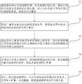
图2是本发明中天线阵列示意图。FIG. 2 is a schematic diagram of an antenna array in the present invention.
具体实施方式Detailed ways
下面将结合附图对本发明的技术方案进行清楚、完整地描述,显然,所描述的实施例是本发明一部分实施例,而不是全部的实施例。基于本发明中的实施例,本领域普通技术人员在没有做出创造性劳动前提下所获得的所有其他实施例,都属于本发明保护的范围。The technical solutions of the present invention will be clearly and completely described below with reference to the accompanying drawings. Obviously, the described embodiments are a part of the embodiments of the present invention, but not all of the embodiments. Based on the embodiments of the present invention, all other embodiments obtained by those of ordinary skill in the art without creative efforts shall fall within the protection scope of the present invention.
如图1所示,本实施例公开了一种测向定位系统相关干涉仪测向方法,包括以下步骤:As shown in FIG. 1 , the present embodiment discloses a direction finding method for a correlation interferometer of a direction finding positioning system, including the following steps:
步骤S1:根据基站到达角度观测范围、角度观测步进长度、测向天线阵列流形以及载波波长等信息,建立入射角度与导向矢量之间的映射关系,构建导向矢量库;Step S1: According to the base station arrival angle observation range, angle observation step length, direction finding antenna array manifold, carrier wavelength and other information, establish the mapping relationship between the incident angle and the steering vector, and build a steering vector library;
步骤S2:终端广播带有标志信息的数据包信号,数据包信号中包含一段连续的正弦波信号用于测向;Step S2: the terminal broadcasts a data packet signal with flag information, and the data packet signal includes a continuous sine wave signal for direction finding;
步骤S3:基站的中心通信天线接收识别到标志信息后,基站控制射频开关按预设的顺序分时选通测向天线与通信天线接收数据包信号中的正弦波信号;Step S3: after the central communication antenna of the base station receives and identifies the flag information, the base station controls the radio frequency switch to time-division gating the direction finding antenna and the communication antenna in a preset order to receive the sine wave signal in the data packet signal;
步骤S4:对接收信号进行预处理,消除射频通道相位差异、收发载频失配引起的相位差异,构造多通道接收信号R;Step S4: preprocessing the received signal, eliminating the phase difference of the radio frequency channel and the phase difference caused by the mismatch of the receiving and sending carrier frequencies, and constructing a multi-channel received signal R;
步骤S5:基于二维分级搜索算法,结合导向矢量库取得导向矢量A,计算S=AHR,及其能量,取能量最强的角度作为估计值。Step S5: Based on the two-dimensional hierarchical search algorithm, the steering vector A is obtained in combination with the steering vector library, and S=AH R and its energy are calculated, and the angle with the strongest energy is taken as the estimated value.
进一步的,所述步骤S1中包括以下步骤:Further, the step S1 includes the following steps:
步骤S11:基站包含一个阵列天线,阵列天线由一个通信天线阵元与N个测向天线阵元组成,测向天线沿半径为R=λ2的圆周均匀分布,λ为载波波长,阵元间隔弧度ω=2π/N,依次编号1,2,...,N,且阵元1在X轴上,通信天线阵元位于均匀圆阵圆心处,编号为0;Step S11: The base station includes an array antenna. The array antenna is composed of a communication antenna element and N direction finding antenna elements. The direction finding antennas are evenly distributed along a circle with a radius of R=λ2, where λ is the carrier wavelength, and the array element is spaced in radians. ω=2π/N, numbered 1,2,...,N in sequence, and array element 1 is on the X-axis, the communication antenna array element is located at the center of the uniform circular array, and the number is 0;
步骤S12:俯仰角θ为信号入射方向与XOY平面夹角,其最大值、最小值以及步进长度分别为θmax,θmin以及θstep;Step S12: the pitch angle θ is the angle between the signal incident direction and the XOY plane, and its maximum value, minimum value and step length are respectively θmax , θmin and θstep ;
方位角


俯仰角θ与方位角


其中,in,

步骤S13:根据俯仰角与方位角观测范围[θmin,θmax]与


进一步的,所述步骤S2中包括以下步骤:Further, the step S2 includes the following steps:
步骤S21:标志信息至少包括用于识别区分终端的MAC地址与用于识别包含正弦波的特征标识码;Step S21: the flag information at least includes a MAC address for identifying and distinguishing terminals and a feature identification code for identifying a sine wave;
步骤S22:正弦波信号s(t)由测向信息码经调制后生成,频率为fsin,即s(t)=exp{j2πfsint}。Step S22: The sine wave signal s(t) is generated by modulating the direction finding information code, and the frequency is fsin , that is, s(t)=exp{j2πfsin t}.
进一步的,所述步骤S3中包括以下步骤:Further, the step S3 includes the following steps:
步骤S31:射频开关选通通信天线接收空间无线电信号;Step S31: the radio frequency switch gates the communication antenna to receive the space radio signal;
步骤S32:当检测到用于识别包含正弦波的特征标识码时,基站控制射频开关按预设的顺序分时选通测向天线与通信天线接收正弦波信号;Step S32: when detecting the feature identification code for identifying the sine wave, the base station controls the radio frequency switch to time-division gating the direction finding antenna and the communication antenna to receive the sine wave signal in a preset order;
步骤S33:预设的阵元选通顺序为通信天线阵元、测向天线阵元、通信天线阵元、测向天线阵元交替选通,可选的,循环几轮选通顺序,最终选通通信天线阵元;Step S33: The preset array element gating sequence is alternately gating the communication antenna array element, the direction finding antenna array element, the communication antenna array element, and the direction finding antenna array element. communication antenna array element;
步骤S34:选通时长Tsw,且2fsinTsw为整数;Step S34: gating duration Tsw , and 2fsin Tsw is an integer;
步骤S35:选通阵元接收波长为λ由天线阵俯仰角θ、方位角
当通信天线选通时,即i=0,n=0,2,...,2N-2时,When the communication antenna is gated, i.e. i=0, n=0, 2,..., 2N-2,
yi(t)=s(t-nTsw)exp{j2πΔf(t-nTsw)},yi (t)=s(t-nTsw )exp{j2πΔf(t-nTsw )},
当测向天线选通时,即i=1,...,N,n=1,3,...,2N-1时,When the DF antenna is gated, i.e. i=1,...,N,n=1,3,...,2N-1,

其中,Δf为收发载频失配引起的频率差异;Among them, Δf is the frequency difference caused by the mismatch of the transceiver carrier frequency;
步骤S36:收发载频失配是由终端-基站之间相互运动引入的多普勒频偏与收发本振失配共同作用产生的。Step S36: The mismatch of the transceiving carrier frequency is caused by the combined action of the Doppler frequency offset introduced by the mutual movement between the terminal and the base station and the mismatch of the transceiving local oscillator.
进一步的,所述步骤S4中包括以下步骤:Further, the step S4 includes the following steps:
步骤S41:补偿射频通道相位差异,相位差异通过天线阵远场法线方向的静止信号源进行标校,因为此时各天线接收信号中不存在入射角度引入的相位差异,解析的相位差异由射频通道与元器件以及收发载频失配引起;Step S41: Compensate the phase difference of the radio frequency channel, and the phase difference is calibrated by the static signal source in the normal direction of the far field of the antenna array, because there is no phase difference introduced by the incident angle in the received signal of each antenna at this time, and the analyzed phase difference is determined by the radio frequency. Caused by mismatch between channels and components, as well as transceiver carrier frequency;
步骤S42:补偿收发载频失配引起的相位差异,并构造多通道接收信号ri(t),i=1,2,...,N,满足:Step S42: Compensate the phase difference caused by the mismatch of the transceiving carrier frequency, and construct a multi-channel received signal ri (t), i=1, 2, . . . , N, satisfying:

其中,exp{jγ}为常量,得到:where exp{jγ} is a constant, and we get:

进一步的,所述步骤S5中包括以下步骤:Further, the step S5 includes the following steps:
步骤S51:采用M级二维分级搜索,根据总体搜索次数最小化原则,确定各级俯仰角、方位角范围长度,段数,段长;Step S51: M-level two-dimensional hierarchical search is adopted, and according to the principle of minimizing the total number of searches, the range lengths of the pitch angles and azimuth angles of all levels, the number of segments, and the segment lengths are determined;
步骤S52:从第一级开始,根据各级搜索中,各段俯仰角方位角组合对应的导向矢量A,计算全部组合S=AHR及其能量P=∑si2,si为数据矢量S中的第i个元素,选择能量最大对应的俯仰角、方位角所在段作为下一级搜索范围,直到第M级;Step S52: Starting from the first level, according to the steering vector A corresponding to each segment of the pitch and azimuth combination in the search at each level, calculate all combinations S=A HR and its energy P=∑si2 , where si is the data For the i-th element in the vector S, select the segment where the pitch angle and azimuth angle corresponding to the maximum energy are located as the next-level search range, until the M-th level;
步骤S53:将第M级能量最大对应的俯仰角、方位角作为到达角度估计值。Step S53: Take the pitch angle and the azimuth angle corresponding to the M-th maximum energy as the estimated value of the angle of arrival.
优选的,所述步骤S51中,所述总体搜索次数最小化确定采用M级二维分级搜索;Preferably, in the step S51, it is determined that the overall search times are minimized to adopt M-level two-dimensional hierarchical search;
第一级俯仰角范围长度


第一级方位角范围长度


第一级俯仰角、方位角组合数为
第m级俯仰角范围长度


第m级方位角范围长度


第m级俯仰角、方位角组合数为
第M级俯仰角范围长度


第M级方位角范围长度


第M级俯仰角、方位角组合数为
确定各级俯仰角、方位角段数

实施例:Example:
基站包含一个阵列天线,阵列天线由一个通信天线阵元与6个测向天线阵元组成,天线阵列如图2所示,测向天线沿半径为R=λ/2的圆周均匀分布,载波波长为λ=12.5cm,阵元间隔弧度ω=π/3,依次编号1,2,...,6,且阵元1在X轴上,通信天线阵元位于均匀圆阵圆心处,编号为0;The base station contains an array antenna. The array antenna consists of a communication antenna element and 6 direction-finding antenna elements. The antenna array is shown in Figure 2. The direction-finding antennas are evenly distributed along a circle with a radius of R=λ/2. The carrier wavelength is λ=12.5cm, the array element interval is radian ω=π/3, numbered 1, 2,..., 6 in turn, and the array element 1 is on the X axis, the communication antenna array element is located at the center of the uniform circular array, and the number is 0;
俯仰角θ为信号入射方向与XOY平面夹角,其最大值、最小值以及步进长度分别为θmax=π/2,θmin=0以及θstep=π/180;The pitch angle θ is the angle between the signal incident direction and the XOY plane, and its maximum value, minimum value and step length are respectively θmax =π/2, θmin =0 and θstep =π/180;
方位角


俯仰角θ与方位角


其中,in,

根据俯仰角与方位角观测范围[0,π/2]与[0,2π]、步进长度θstep与

终端采用蓝牙通信协议广播带有标志信息的数据包信号,数据包信号中包含一段连续的正弦波信号用于测向,数据包中包含如下信息:The terminal uses the Bluetooth communication protocol to broadcast the data packet signal with the flag information. The data packet signal contains a continuous sine wave signal for direction finding, and the data packet contains the following information:
字节编号7~12表示用于识别区分终端的MAC地址;Byte numbers 7 to 12 represent the MAC address used to identify and distinguish terminals;
字节编号15~17表示用于识别包含正弦波的特征标识码;Byte numbers 15 to 17 represent the feature identification code used to identify the sine wave;
字节编号27~43表示测向信息码,如采用CH37广播信道,信号带宽1MHz,所述测向信息码为:0xCC、0x27、0x45、0x67、0xF7、0xDB、0x34、0xC4、0x03、0x8E、0x5C、0x0B、0xAA、0x97、0x30、0x56、0xE6,经过CH37信道白化滤波以及GFSK调制后生成的信号是一个250kHz的正弦波,即fsin=250kHz。Byte numbers 27 to 43 represent the direction finding information code. If the CH37 broadcast channel is used and the signal bandwidth is 1MHz, the direction finding information code is: 0xCC, 0x27, 0x45, 0x67, 0xF7, 0xDB, 0x34, 0xC4, 0x03, 0x8E, 0x5C, 0x0B, 0xAA, 0x97, 0x30, 0x56, 0xE6, the signal generated after CH37 channel whitening filtering and GFSK modulation is a 250kHz sine wave, that is, fsin =250kHz.
当检测到用于识别包含正弦波的特征标识码时,基站控制射频开关按预设的顺序分时选通测向天线与通信天线接收正弦波信号,预设的阵元选通顺序为0,1,0,2,0,3,……,0,6,选通时长Tsw=2μs,2fsinTsw=1;When the feature identification code used to identify the sine wave is detected, the base station controls the radio frequency switch to time-division gating the direction finding antenna and the communication antenna to receive the sine wave signal in a preset sequence. The preset array element gating sequence is 0, 1, 0, 2, 0, 3,..., 0, 6, the gate duration Tsw =2μs, 2fsin Tsw =1;
选通阵元接收波长为λ由天线阵俯仰角θ、方位角
当通信天线选通时,即i=0,n=0,2,...,2N-2时,When the communication antenna is gated, i.e. i=0, n=0, 2,..., 2N-2,
yi(t)=s(t-nTsw)exp{j2πΔf(t-nTsw)},yi (t)=s(t-nTsw )exp{j2πΔf(t-nTsw )},
当测向天线选通时,即i=1,...,N,n=1,3,...,2N-1时,When the DF antenna is gated, i.e. i=1,...,N,n=1,3,...,2N-1,

其中,Δf为收发载频失配引起的频率差异。Among them, Δf is the frequency difference caused by the mismatch of the transmit and receive carrier frequencies.
补偿射频通道相位差异,相位差异通过天线阵远场法线方向的静止信号源进行标校,因为此时各天线接收信号中不存在入射角度引入的相位差异,相位差异由射频通道、元器件以及收发本振失配引起;Compensate the phase difference of the RF channel. The phase difference is calibrated by the static signal source in the normal direction of the far field of the antenna array, because there is no phase difference caused by the incident angle in the received signal of each antenna at this time. The phase difference is determined by the RF channel, components and It is caused by the mismatch of the transceiver local oscillator;
补偿收发载频失配引起的相位差异,并构造多通道接收信号ri(t),i=1,2,...,N,满足:Compensate the phase difference caused by the mismatch of the receiving and sending carrier frequencies, and construct the multi-channel received signal ri (t), i=1,2,...,N, satisfying:

其中,exp{jγ}为常量,得到:where exp{jγ} is a constant, and we get:

进一步地,采用M级二维分级搜索,根据总体搜索次数最小化原则,确定各级俯仰角、方位角度围长度,段数,段长;Further, M-level two-dimensional hierarchical search is adopted, and according to the principle of minimizing the overall search times, the enclosing lengths, the number of segments, and the segment lengths of the pitch angles and azimuth angles of all levels are determined;
确定采用M级二维分级搜索;Determine to use M-level two-dimensional hierarchical search;
第一级俯仰角范围长度


第一级方位角范围长度


第一级俯仰角、方位角组合数为
第m级俯仰角范围长度


第m级方位角范围长度


第m级俯仰角、方位角组合数为
第M级俯仰角范围长度


第M级方位角范围长度


第M级俯仰角、方位角组合数为
确定各级俯仰角、方位角段数

从第一级开始,根据各级搜索中,各段俯仰角方位角组合对应的导向矢量A,计算全部组合S=AHR及其能量P=∑|si|2,si为数据矢量S中的第i个元素,选择能量最大对应的俯仰角、方位角所在段作为下一级搜索范围,直到第M级;Starting from the first level, according to the steering vector A corresponding to the combination of the pitch and azimuth angles of each segment in the search at each level, calculate the total combination S=AH R and its energy P=∑|si |2 , where si is the data vector For the i-th element in S, select the segment where the pitch angle and azimuth angle corresponding to the maximum energy are located as the next-level search range, until the M-th level;
将第M级能量最大对应的俯仰角、方位角作为到达角度估计值。The pitch angle and azimuth angle corresponding to the maximum energy of the M-th stage are taken as the estimated value of the angle of arrival.
以上所述,仅为本发明较佳的具体实施方式,但本发明的保护范围并不局限于此,任何熟悉本技术领域的技术人员在本发明揭露的技术范围内,可轻易想到的变化或替换,都应涵盖在本发明的保护范围之内。因此,本发明的保护范围应该以权利要求的保护范围为准。The above description is only a preferred embodiment of the present invention, but the protection scope of the present invention is not limited to this. Substitutions should be covered within the protection scope of the present invention. Therefore, the protection scope of the present invention should be subject to the protection scope of the claims.
Claims (7)


Priority Applications (1)
| Application Number | Priority Date | Filing Date | Title |
|---|---|---|---|
| CN202210556182.5ACN115113134B (en) | 2022-05-20 | 2022-05-20 | A direction finding method for a direction finding positioning system using a correlation interferometer |
Applications Claiming Priority (1)
| Application Number | Priority Date | Filing Date | Title |
|---|---|---|---|
| CN202210556182.5ACN115113134B (en) | 2022-05-20 | 2022-05-20 | A direction finding method for a direction finding positioning system using a correlation interferometer |
Publications (2)
| Publication Number | Publication Date |
|---|---|
| CN115113134Atrue CN115113134A (en) | 2022-09-27 |
| CN115113134B CN115113134B (en) | 2025-07-04 |
Family
ID=83326065
Family Applications (1)
| Application Number | Title | Priority Date | Filing Date |
|---|---|---|---|
| CN202210556182.5AActiveCN115113134B (en) | 2022-05-20 | 2022-05-20 | A direction finding method for a direction finding positioning system using a correlation interferometer |
Country Status (1)
| Country | Link |
|---|---|
| CN (1) | CN115113134B (en) |
Citations (8)
| Publication number | Priority date | Publication date | Assignee | Title |
|---|---|---|---|---|
| US4633257A (en)* | 1983-11-14 | 1986-12-30 | Sanders Associates, Inc. | Acquisition system employing circular array |
| US20050259006A1 (en)* | 2004-05-24 | 2005-11-24 | Samsung Electronics Co., Ltd. | Beam forming apparatus and method using interference power estimation in an array antenna system |
| WO2006016408A1 (en)* | 2004-08-12 | 2006-02-16 | Fujitsu Limited | Radio wave arrival direction adaptive deduction tracking method and device |
| CN102520390A (en)* | 2011-11-23 | 2012-06-27 | 华中科技大学 | Two-dimensional MUSIC (multiple signal classification) direction-detecting device for uniform circular array |
| CN110161489A (en)* | 2019-05-21 | 2019-08-23 | 西安电子科技大学 | A kind of strong and weak signals direction-finding method based on pseudo- frame |
| CN111366891A (en)* | 2020-03-23 | 2020-07-03 | 电子科技大学 | A Single Snapshot Direction Finding Method for Uniform Circular Arrays Based on Pseudo-Covariance Matrix |
| US20210116531A1 (en)* | 2020-12-24 | 2021-04-22 | Intel Corporation | Radar apparatus, system, and method of generating angle of arrival (aoa) information |
| CN113655435A (en)* | 2021-07-22 | 2021-11-16 | 深圳云里物里科技股份有限公司 | Method and device for determining angle of arrival, signal receiving equipment, system and medium |
- 2022
- 2022-05-20CNCN202210556182.5Apatent/CN115113134B/enactiveActive
Patent Citations (8)
| Publication number | Priority date | Publication date | Assignee | Title |
|---|---|---|---|---|
| US4633257A (en)* | 1983-11-14 | 1986-12-30 | Sanders Associates, Inc. | Acquisition system employing circular array |
| US20050259006A1 (en)* | 2004-05-24 | 2005-11-24 | Samsung Electronics Co., Ltd. | Beam forming apparatus and method using interference power estimation in an array antenna system |
| WO2006016408A1 (en)* | 2004-08-12 | 2006-02-16 | Fujitsu Limited | Radio wave arrival direction adaptive deduction tracking method and device |
| CN102520390A (en)* | 2011-11-23 | 2012-06-27 | 华中科技大学 | Two-dimensional MUSIC (multiple signal classification) direction-detecting device for uniform circular array |
| CN110161489A (en)* | 2019-05-21 | 2019-08-23 | 西安电子科技大学 | A kind of strong and weak signals direction-finding method based on pseudo- frame |
| CN111366891A (en)* | 2020-03-23 | 2020-07-03 | 电子科技大学 | A Single Snapshot Direction Finding Method for Uniform Circular Arrays Based on Pseudo-Covariance Matrix |
| US20210116531A1 (en)* | 2020-12-24 | 2021-04-22 | Intel Corporation | Radar apparatus, system, and method of generating angle of arrival (aoa) information |
| CN113655435A (en)* | 2021-07-22 | 2021-11-16 | 深圳云里物里科技股份有限公司 | Method and device for determining angle of arrival, signal receiving equipment, system and medium |
Non-Patent Citations (11)
| Title |
|---|
| REN XIAO-SONG ET AL.: "Correlative direction finding based on pattern fitting and robust beamforming", SYSTEMS ENGINEERING AND ELECTRONICS, vol. 37, no. 03, 31 July 2015 (2015-07-31)* |
| REN XIAO-SONG ET AL.: "Correlative direction finding based on pattern fitting and robust beamforming", SYSTEMS ENGINEERING AND ELECTRONICS, vol. 37, no. 3, 30 July 2015 (2015-07-30)* |
| 冯洋: "宽带天线阵列及测向算法技术研究", 中国优秀硕士学位论文全文库信息科技辑, no. 05, 15 May 2021 (2021-05-15)* |
| 冯洋: "宽带天线阵列及测向算法技术研究", 中国优秀硕士学位论文全文数据库信息科技辑, no. 05, 15 May 2021 (2021-05-15)* |
| 卢舟等: "基于优化MUSIC算法的云闪定位技术研究", 气象研究与应用, vol. 39, no. 01, 15 March 2018 (2018-03-15)* |
| 卢舟等: "基于优化MUSIC算法的云闪定位技术研究", 气象研究与应用, vol. 39, no. 01, 31 March 2018 (2018-03-31)* |
| 宗平等: "认知无线电技术在ZigBee中的应用研究", 计算机技术与发展, vol. 22, no. 08, 30 September 2012 (2012-09-30)* |
| 宗平等: "认知无线电技术在ZigBee中的应用研究", 计算机技术与发展, vol. 22, no. 08, 31 August 2012 (2012-08-31)* |
| 张智锋等: "低信噪比下相关干涉仪测向处理方法", 舰船电子对抗, vol. 32, no. 06, 25 December 2009 (2009-12-25)* |
| 张智锋等: "低信噪比下相关干涉仪测向处理方法", 舰船电子对抗, vol. 32, no. 06, 31 December 2009 (2009-12-31)* |
| 魏子翔等: "基于对称天线相位干涉仪的入射角估计及跟踪", 电子与信息学报, vol. 37, no. 10, 31 October 2015 (2015-10-31)* |
Also Published As
| Publication number | Publication date |
|---|---|
| CN115113134B (en) | 2025-07-04 |
Similar Documents
| Publication | Publication Date | Title |
|---|---|---|
| Wu et al. | mmTrack: Passive multi-person localization using commodity millimeter wave radio | |
| US9647868B2 (en) | Handling signals | |
| US20220268912A1 (en) | Method and apparatus for locating target object | |
| Saxena et al. | Experimental analysis of RSSI-based location estimation in wireless sensor networks | |
| Jiang et al. | ALRD: AoA localization with RSSI differences of directional antennas for wireless sensor networks | |
| US10206194B1 (en) | Narrowband single base location system | |
| CN107741580B (en) | Bluetooth positioning method | |
| Chen et al. | AWL: Turning spatial aliasing from foe to friend for accurate WiFi localization | |
| US20240337726A1 (en) | Sensing method and apparatus, sensing configuration method and apparatus, and a communication device | |
| Paulino et al. | Self-localization via circular bluetooth 5.1 antenna array receiver | |
| Suchanski et al. | Radio environment maps for military cognitive networks: Deployment of sensors vs. map quality | |
| Tong et al. | Triangular antenna layout facilitates deployability of CSI indoor localization systems | |
| Liu et al. | Indoor passive localization with channel state information using a single access point | |
| WO2024131691A1 (en) | Sensing processing method, device, communication equipment, and readable storage medium | |
| Xiong | Pushing the limits of indoor localization in today’s Wi-Fi networks | |
| Pisa et al. | On the generalization of deep learning models for aoa estimation in bluetooth indoor scenarios | |
| Liu et al. | HiLoc: Sub-meter level indoor localization using a single access point with distributed antennas in wireless sensor networks | |
| CN115113134A (en) | A direction finding method of correlation interferometer for direction finding positioning system | |
| US20250130305A1 (en) | Positioning with carrier phase | |
| TW202515143A (en) | Methods and apparatus for sensing beam management in integrated sensing and communications system | |
| Tian et al. | RTIL: A real-time indoor localization system by using angle of arrival of commodity WiFi signal | |
| Zhou et al. | An Efficient Phase Interferometer Direction-Finding Algorithm Based on Circular Array | |
| Bingbing et al. | An indoor positioning algorithm and its experiment research based on RFID | |
| CN118282541A (en) | Transmission processing method, device, terminal and network side equipment | |
| CN114966533B (en) | Direction finding method of phase interferometer of direction finding positioning system |
Legal Events
| Date | Code | Title | Description |
|---|---|---|---|
| PB01 | Publication | ||
| PB01 | Publication | ||
| SE01 | Entry into force of request for substantive examination | ||
| SE01 | Entry into force of request for substantive examination | ||
| GR01 | Patent grant | ||
| GR01 | Patent grant |