CN115105175A - Puncture navigation system, method, device and storage medium and puncture device - Google Patents
Puncture navigation system, method, device and storage medium and puncture deviceDownload PDFInfo
- Publication number
- CN115105175A CN115105175ACN202210772136.9ACN202210772136ACN115105175ACN 115105175 ACN115105175 ACN 115105175ACN 202210772136 ACN202210772136 ACN 202210772136ACN 115105175 ACN115105175 ACN 115105175A
- Authority
- CN
- China
- Prior art keywords
- puncture
- coordinate system
- image
- needle
- puncture needle
- Prior art date
- Legal status (The legal status is an assumption and is not a legal conclusion. Google has not performed a legal analysis and makes no representation as to the accuracy of the status listed.)
- Granted
Links
- 238000000034methodMethods0.000titleclaimsabstractdescription74
- 230000033001locomotionEffects0.000claimsabstractdescription204
- 239000000523sampleSubstances0.000claimsabstractdescription133
- 238000006243chemical reactionMethods0.000claimsabstractdescription107
- 238000012545processingMethods0.000claimsabstractdescription54
- 230000009466transformationEffects0.000claimsabstractdescription24
- 238000002604ultrasonographyMethods0.000claimsdescription180
- 238000003780insertionMethods0.000claimsdescription31
- 230000037431insertionEffects0.000claimsdescription31
- 239000011295pitchSubstances0.000claimsdescription21
- 238000002372labellingMethods0.000claimsdescription13
- 230000000877morphologic effectEffects0.000claimsdescription13
- 238000004590computer programMethods0.000claimsdescription12
- 238000012937correctionMethods0.000claimsdescription8
- 230000004044responseEffects0.000claimsdescription8
- 238000004891communicationMethods0.000claims5
- 230000004888barrier functionEffects0.000claims2
- 230000003287optical effectEffects0.000abstractdescription11
- 239000003550markerSubstances0.000abstractdescription8
- 238000010586diagramMethods0.000description36
- 230000007246mechanismEffects0.000description23
- 239000011159matrix materialSubstances0.000description21
- 230000008569processEffects0.000description20
- 210000001519tissueAnatomy0.000description15
- 239000000203mixtureSubstances0.000description13
- 210000002307prostateAnatomy0.000description10
- 206010028980NeoplasmDiseases0.000description8
- 230000000694effectsEffects0.000description7
- 230000009286beneficial effectEffects0.000description6
- 230000003902lesionEffects0.000description6
- 230000035515penetrationEffects0.000description6
- 238000004364calculation methodMethods0.000description5
- 230000006870functionEffects0.000description5
- 239000003086colorantSubstances0.000description4
- 238000013461designMethods0.000description3
- 238000003384imaging methodMethods0.000description3
- 238000010317ablation therapyMethods0.000description2
- 238000001574biopsyMethods0.000description2
- 201000011510cancerDiseases0.000description2
- 238000001514detection methodMethods0.000description2
- 210000001503jointAnatomy0.000description2
- 238000013188needle biopsyMethods0.000description2
- 210000000056organAnatomy0.000description2
- 230000000644propagated effectEffects0.000description2
- 208000018084Bone neoplasmDiseases0.000description1
- 206010068771Soft tissue neoplasmDiseases0.000description1
- 238000002679ablationMethods0.000description1
- 230000009471actionEffects0.000description1
- 230000005540biological transmissionEffects0.000description1
- 238000004422calculation algorithmMethods0.000description1
- 230000008878couplingEffects0.000description1
- 238000010168coupling processMethods0.000description1
- 238000005859coupling reactionMethods0.000description1
- 238000011161developmentMethods0.000description1
- 238000002059diagnostic imagingMethods0.000description1
- 201000010099diseaseDiseases0.000description1
- 208000037265diseases, disorders, signs and symptomsDiseases0.000description1
- 210000002310elbow jointAnatomy0.000description1
- 230000005684electric fieldEffects0.000description1
- 230000003631expected effectEffects0.000description1
- 238000000605extractionMethods0.000description1
- 239000000835fiberSubstances0.000description1
- 230000036541healthEffects0.000description1
- 210000002216heartAnatomy0.000description1
- 238000012333histopathological diagnosisMethods0.000description1
- 238000010191image analysisMethods0.000description1
- 238000002513implantationMethods0.000description1
- 210000004185liverAnatomy0.000description1
- 238000013507mappingMethods0.000description1
- 239000013307optical fiberSubstances0.000description1
- 210000000496pancreasAnatomy0.000description1
- 239000002245particleSubstances0.000description1
- 230000000704physical effectEffects0.000description1
- 239000004065semiconductorSubstances0.000description1
- 239000007787solidSubstances0.000description1
- 238000002560therapeutic procedureMethods0.000description1
- 230000001131transforming effectEffects0.000description1
- 230000000007visual effectEffects0.000description1
- 238000012800visualizationMethods0.000description1
Images


Classifications
- A—HUMAN NECESSITIES
- A61—MEDICAL OR VETERINARY SCIENCE; HYGIENE
- A61B—DIAGNOSIS; SURGERY; IDENTIFICATION
- A61B17/00—Surgical instruments, devices or methods
- A61B17/34—Trocars; Puncturing needles
- A61B17/3403—Needle locating or guiding means
- A—HUMAN NECESSITIES
- A61—MEDICAL OR VETERINARY SCIENCE; HYGIENE
- A61B—DIAGNOSIS; SURGERY; IDENTIFICATION
- A61B17/00—Surgical instruments, devices or methods
- A61B17/34—Trocars; Puncturing needles
- A61B17/3403—Needle locating or guiding means
- A61B2017/3405—Needle locating or guiding means using mechanical guide means
- A61B2017/3409—Needle locating or guiding means using mechanical guide means including needle or instrument drives
- A—HUMAN NECESSITIES
- A61—MEDICAL OR VETERINARY SCIENCE; HYGIENE
- A61B—DIAGNOSIS; SURGERY; IDENTIFICATION
- A61B17/00—Surgical instruments, devices or methods
- A61B17/34—Trocars; Puncturing needles
- A61B17/3403—Needle locating or guiding means
- A61B2017/3413—Needle locating or guiding means guided by ultrasound
Landscapes
- Health & Medical Sciences (AREA)
- Surgery (AREA)
- Life Sciences & Earth Sciences (AREA)
- Biomedical Technology (AREA)
- Nuclear Medicine, Radiotherapy & Molecular Imaging (AREA)
- Engineering & Computer Science (AREA)
- Pathology (AREA)
- Heart & Thoracic Surgery (AREA)
- Medical Informatics (AREA)
- Molecular Biology (AREA)
- Animal Behavior & Ethology (AREA)
- General Health & Medical Sciences (AREA)
- Public Health (AREA)
- Veterinary Medicine (AREA)
- Ultra Sonic Daignosis Equipment (AREA)
Abstract
Translated fromChinese
Description
Translated fromChinese技术领域technical field
本公开的实施例涉及一种穿刺导航系统、方法、设备与存储介质以及穿刺装置。Embodiments of the present disclosure relate to a puncture navigation system, method, apparatus, and storage medium, and a puncture device.
背景技术Background technique
癌症是危害人类健康的主要疾病。对于传统的癌症治疗方法和新近发展起来的以微创消融为特征的热消融疗法,以及粒子植入等消融疗法,由于受适应症、禁忌症、治疗副作用、热效应等因素的限制,使得其临床应用受到一定的局限性。Cancer is a major disease endangering human health. For traditional cancer treatment methods and newly developed thermal ablation therapy characterized by minimally invasive ablation, as well as ablation therapy such as particle implantation, due to the limitations of indications, contraindications, treatment side effects, thermal effects and other factors, its clinical The application is subject to certain limitations.
近年来,随着脉冲生物电学的不断发展,电场脉冲以其非热、微创的生物医学效用受到广泛关注,并逐渐应用于肿瘤的临床治疗。微创疗法往往需要通过穿刺针到达人体内的目标组织区域进行治疗,然而穿刺针通常需要在超声或其他医学影像设备的引导下,配合穿刺模板进行定位,从而到达至预期目标位置。In recent years, with the continuous development of pulsed bioelectricity, electric field pulses have attracted extensive attention for their non-thermal and minimally invasive biomedical effects, and have been gradually applied in the clinical treatment of tumors. Minimally invasive therapy often requires a puncture needle to reach the target tissue area in the human body for treatment. However, the puncture needle usually needs to be positioned with the puncture template under the guidance of ultrasound or other medical imaging equipment to reach the desired target position.
目前,临床上普遍采用穿刺设备与超声探头制成一体的形式,在操作中通过超声图像的引导下进行肿瘤的定位穿刺,但由于超声成像的区域是有限的,并且是一个二维平面,因此只有当穿刺针沿着超声成像平面进入超声成像区域之后才能在超声图像中观察到穿刺设备,无法实时显示穿刺针与肿瘤之间的位置关系,从而导致操作者(例如医生)无法通过观察三维图像中穿刺针与肿瘤部位的相对位置关系,对患者进行精确的穿刺。因此,当前急需一种能够实时显示穿刺针与肿瘤之间的位置关系的导航系统。At present, a puncture device and an ultrasonic probe are commonly used in clinical practice to locate and puncture the tumor under the guidance of ultrasonic images. However, since the area of ultrasonic imaging is limited and is a two-dimensional plane, so The puncture device can only be observed in the ultrasonic image after the puncture needle enters the ultrasonic imaging area along the ultrasonic imaging plane, and the positional relationship between the puncture needle and the tumor cannot be displayed in real time, so that the operator (such as a doctor) cannot observe the three-dimensional image by The relative positional relationship between the puncture needle and the tumor site can be accurately punctured for the patient. Therefore, there is an urgent need for a navigation system that can display the positional relationship between the puncture needle and the tumor in real time.
发明内容SUMMARY OF THE INVENTION
本公开至少一实施例提供了一种用于穿刺装置的穿刺导航系统,所述穿刺装置包括基座、穿刺针、超声探头和具有至少一个穿刺控制件的穿刺控制部,所述穿刺导航系统包括定位模块、超声图像获取模块、穿刺规划模块、坐标系转换模块、第一运动路径确定模块、第二运动路径确定模块和导航处理模块。定位模块配置为基于所述基座对所述穿刺针进行定位,确定所述穿刺针在空间坐标系内的第一三维坐标信息,所述空间坐标系是基于所述基座建立的坐标系。超声图像获取模块配置为获取所述超声探头采集的目标组织的一组超声图像,以确定所述一组超声图像对应的三维超声图像。穿刺规划模块配置为基于所述三维超声图像进行用于所述穿刺针的穿刺规划,以确定穿刺规划信息,其中,所述穿刺规划信息包括所述穿刺针的进针点位置、所述穿刺针的进针方向和所述穿刺针的目标穿刺点位置。坐标系转换模块配置为建立所述超声图像的图像坐标系与所述空间坐标系之间的转换关系,使得基于所述转换关系确定所述第一三维坐标信息在所述图像坐标系内的实时图像位置,以实时地在所述图像坐标系中可视化所述穿刺针与所述目标穿刺点位置之间的相对位置。第一运动路径确定模块配置为在所述图像坐标系中,基于所述穿刺针与所述目标穿刺点位置之间的相对位置确定所述穿刺针的第一运动路径。第二运动路径确定模块配置为基于所述图像坐标系内的所述第一运动路径确定与所述穿刺针具有一预定位置关系的穿刺导向件在所述空间坐标系内的第二运动路径。导航处理模块配置为在所述空间坐标系中,基于所述第二运动路径,通过所述至少一个穿刺控制件进行所述穿刺针的导航。At least one embodiment of the present disclosure provides a puncture navigation system for a puncture device, the puncture device includes a base, a puncture needle, an ultrasonic probe, and a puncture control part having at least one puncture control member, the puncture navigation system includes A positioning module, an ultrasound image acquisition module, a puncture planning module, a coordinate system conversion module, a first motion path determination module, a second motion path determination module, and a navigation processing module. The positioning module is configured to position the puncture needle based on the base, and determine first three-dimensional coordinate information of the puncture needle in a space coordinate system, where the space coordinate system is a coordinate system established based on the base. The ultrasound image acquisition module is configured to acquire a set of ultrasound images of the target tissue acquired by the ultrasound probe to determine a three-dimensional ultrasound image corresponding to the set of ultrasound images. The puncture planning module is configured to perform puncture planning for the puncture needle based on the three-dimensional ultrasound image, to determine puncture planning information, wherein the puncture planning information includes the position of the needle insertion point of the puncture needle, the puncture needle The needle insertion direction and the target puncture point position of the puncture needle. The coordinate system transformation module is configured to establish a transformation relationship between the image coordinate system of the ultrasound image and the space coordinate system, so that the real-time real-time transformation of the first three-dimensional coordinate information in the image coordinate system is determined based on the transformation relationship. image position to visualize the relative position between the puncture needle and the target puncture point location in the image coordinate system in real time. The first motion path determination module is configured to determine, in the image coordinate system, a first motion path of the puncture needle based on a relative position between the puncture needle and the target puncture point position. The second motion path determination module is configured to determine a second motion path of the puncture guide having a predetermined positional relationship with the puncture needle in the space coordinate system based on the first motion path in the image coordinate system. The navigation processing module is configured to navigate the puncture needle through the at least one puncture control member based on the second motion path in the space coordinate system.
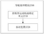
例如,在本公开至少一实施例提供的一种穿刺导航系统中,所述导航处理模块包括:控制件运动轨迹确定单元,配置为基于所述穿刺装置和所述第二运动路径确定所述至少一个穿刺控制件中的每个的运动轨迹;驱动装置,与所述至少一个穿刺控制件驱动连接且配置为驱动所述至少一个穿刺控制件中的每个沿对应的运动轨迹进行运动,以导航所述穿刺针。For example, in a puncture navigation system provided by at least one embodiment of the present disclosure, the navigation processing module includes: a control member motion trajectory determination unit, configured to determine the at least the puncture device and the second motion path based on the puncture device and the second motion path A motion trajectory of each of one puncture control member; a driving device drivingly connected to the at least one puncture control member and configured to drive each of the at least one puncture control member to move along the corresponding motion trajectory to navigate the puncture needle.
例如,在本公开至少一实施例提供的一种穿刺导航系统中,所述穿刺针的所述第一三维坐标信息包括所述穿刺针的针尖在所述空间坐标系内的三维坐标信息,所述穿刺针的所述第一运动路径包括所述穿刺针的针尖的第一运动路径。For example, in a puncture navigation system provided by at least one embodiment of the present disclosure, the first three-dimensional coordinate information of the puncture needle includes the three-dimensional coordinate information of the needle tip of the puncture needle in the space coordinate system, so The first movement path of the puncture needle includes a first movement path of the needle tip of the puncture needle.
例如,在本公开至少一实施例提供的一种穿刺导航系统中,所述至少一个穿刺控制件包括穿刺定位臂组和穿刺深度控制挡板,所述穿刺定位臂组设置在所述基座上,且所述穿刺定位臂组配置为对所述穿刺针进行穿刺定位,所述穿刺深度控制挡板包括所述穿刺导向件;所述穿刺导向件为供所述穿刺针通过的非闭合定位孔,所述第二运动路径确定模块包括:第一确定单元,配置为基于所述穿刺针在所述图像坐标系内的穿刺针图像规格和所述第一运动路径确定所述非闭合定位孔在所述图像坐标系内的第三运动路径;第二确定单元,配置为基于所述转换关系和所述图像坐标系中的所述第三运动路径确定所述非闭合定位孔在所述空间坐标系内的所述第二运动路径。For example, in a puncture navigation system provided by at least one embodiment of the present disclosure, the at least one puncture control member includes a puncture positioning arm set and a puncture depth control baffle, and the puncture positioning arm set is provided on the base , and the puncture positioning arm group is configured to perform puncture positioning on the puncture needle, and the puncture depth control baffle includes the puncture guide; the puncture guide is a non-closed positioning hole for the puncture needle to pass through , the second movement path determination module includes: a first determination unit configured to determine the position of the non-closed positioning hole in the a third motion path in the image coordinate system; a second determination unit configured to determine the spatial coordinates of the non-closed positioning hole based on the conversion relationship and the third motion path in the image coordinate system the second motion path within the system.
例如,在本公开至少一实施例提供的一种穿刺导航系统中,所述定位模块配置为根据所述非闭合定位孔在所述空间坐标系内的三维坐标信息和所述穿刺针在所述空间坐标系内的穿刺针实际物理规格确定所述穿刺针的所述第一三维坐标信息。For example, in a puncture navigation system provided by at least one embodiment of the present disclosure, the positioning module is configured to be based on the three-dimensional coordinate information of the non-closed positioning hole in the space coordinate system and the position of the puncture needle in the The actual physical specification of the puncture needle in the space coordinate system determines the first three-dimensional coordinate information of the puncture needle.
例如,本公开至少一实施例提供的一种穿刺导航系统还包括显示模块,其中,所述显示模块配置为实时地可视化以下的至少一种:所述超声图像、所述三维超声图像、所述穿刺针的针尖、所述穿刺针的针尖与所述目标穿刺点位置之间的相对位置、所述穿刺针的第一运动路径。For example, a puncture navigation system provided by at least one embodiment of the present disclosure further includes a display module, wherein the display module is configured to visualize at least one of the following in real time: the ultrasound image, the three-dimensional ultrasound image, the The needle tip of the puncture needle, the relative position between the needle tip of the puncture needle and the target puncture point position, and the first movement path of the puncture needle.
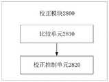
例如,本公开至少一实施例提供的一种穿刺导航系统还包括校正模块,其中,所述校正模块包括:比较单元,配置为比较所述穿刺规划信息的所述进针方向和所述显示模块实时可视化的所述第一运动路径的当前方向,确定所述进针方向与所述当前方向之间的偏差值;校正控制单元,配置为:响应于所述偏差值大于等于预设角度偏差,基于所述偏差值更新所述穿刺针的第一运动路径以更新所述第二运动路径,使得所述导航处理模块基于更新后的第二运动路径,通过所述至少一个穿刺控制件进行所述穿刺针的导航,直至所述进针方向与所述当前方向之间的偏差值小于所述预设角度偏差。For example, a puncture navigation system provided by at least one embodiment of the present disclosure further includes a correction module, wherein the correction module includes: a comparison unit configured to compare the needle insertion direction of the puncture planning information with the display module The current direction of the first motion path visualized in real time is used to determine the deviation value between the needle advancing direction and the current direction; the correction control unit is configured to: in response to the deviation value being greater than or equal to a preset angle deviation, The first motion path of the puncture needle is updated based on the deviation value to update the second motion path, so that the navigation processing module performs the said at least one puncture control element based on the updated second motion path Navigation of the puncture needle until the deviation value between the needle insertion direction and the current direction is less than the preset angle deviation.
例如,在本公开至少一实施例提供的一种穿刺导航系统中,所述定位模块还配置为对所述超声探头进行定位,确定所述超声探头在所述空间坐标系内的第二三维坐标信息。For example, in a puncture navigation system provided in at least one embodiment of the present disclosure, the positioning module is further configured to position the ultrasonic probe and determine the second three-dimensional coordinate of the ultrasonic probe in the space coordinate system information.
例如,在本公开至少一实施例提供的一种穿刺导航系统中,所述基座的中心作为所述空间坐标系的原点或所述基座上与所述至少一个穿刺控制件中对应的穿刺控制件进行连接的位置处作为所述空间坐标系的原点,使得所述定位模块基于所述穿刺针与所述基座之间的位置关系确定所述穿刺针的所述第一三维坐标信息,以及基于所述超声探头与所述基座之间的位置关系确定所述超声探头的所述第二三维坐标信息。For example, in a puncture navigation system provided by at least one embodiment of the present disclosure, the center of the base serves as the origin of the spatial coordinate system or the puncture on the base corresponding to the at least one puncture control member The position where the control member is connected is used as the origin of the spatial coordinate system, so that the positioning module determines the first three-dimensional coordinate information of the puncture needle based on the positional relationship between the puncture needle and the base, and determining the second three-dimensional coordinate information of the ultrasonic probe based on the positional relationship between the ultrasonic probe and the base.
例如,在本公开至少一实施例提供的一种穿刺导航系统中,所述坐标系转换模块包括:坐标系转换单元,配置为基于所述超声图像和所述超声探头的第二三维坐标信息将所述超声图像的图像坐标系转换至所述空间坐标系,以建立所述图像坐标系与所述空间坐标系之间的所述转换关系。For example, in a puncture navigation system provided by at least one embodiment of the present disclosure, the coordinate system conversion module includes: a coordinate system conversion unit configured to convert the ultrasonic image and the second three-dimensional coordinate information of the ultrasonic probe into The image coordinate system of the ultrasound image is converted to the space coordinate system to establish the conversion relationship between the image coordinate system and the space coordinate system.
例如,在本公开至少一实施例提供的一种穿刺导航系统中,所述坐标系转换单元包括:形态学图像处理单元,配置为对所述超声图像进行形态学图像处理以确定目标图像区域;像素统计单元,配置为基于所述目标图像区域获取像素统计分布;转换处理单元,配置为基于所述像素统计分布图以及预先确定的所述超声探头的直径,确定所述超声探头的直径与所述超声探头的直径所占用的像素间距个数之间的转换比率;转换建立单元,配置为基于所述转换比率和所述第二三维坐标信息,将所述图像坐标系转换至所述空间坐标系。For example, in a puncture navigation system provided by at least one embodiment of the present disclosure, the coordinate system conversion unit includes: a morphological image processing unit configured to perform morphological image processing on the ultrasound image to determine a target image area; A pixel statistics unit, configured to obtain a pixel statistical distribution based on the target image area; a conversion processing unit, configured to determine, based on the pixel statistical distribution map and the predetermined diameter of the ultrasonic probe, the difference between the diameter of the ultrasonic probe and the predetermined diameter of the ultrasonic probe. a conversion ratio between the number of pixel pitches occupied by the diameter of the ultrasonic probe; a conversion establishment unit configured to convert the image coordinate system to the space coordinate based on the conversion ratio and the second three-dimensional coordinate information Tie.
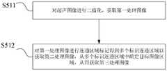
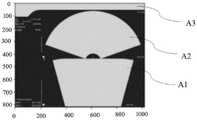
例如,在本公开至少一实施例提供的一种穿刺导航系统中,所述形态学图像处理单元包括:二值化子单元,配置为对所述超声图像进行二值化以获取第一处理图像;标签化处理子单元,配置为通过对所述第一处理图像进行区域连通与标记得到多个标识连通区域以获取第二处理图像,从所述多个标识连通区域中获取所述目标图像区域,从而获取第三处理图像,其中,所述目标图像区域包括所述多个标识连通区域中的区域最大和次大的两个目标标识连通区域。For example, in a puncture navigation system provided by at least one embodiment of the present disclosure, the morphological image processing unit includes: a binarization subunit configured to binarize the ultrasound image to obtain a first processed image The labeling processing subunit is configured to obtain a plurality of marked connected regions by performing regional connectivity and marking on the first processed image to obtain a second processed image, and obtain the target image region from the plurality of marked connected regions , so as to obtain a third processed image, wherein the target image region includes two target identified connected regions with the largest and second largest regions among the plurality of identified connected regions.
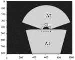
例如,在本公开至少一实施例提供的一种穿刺导航系统中,所述转换处理单元包括:界定处理子单元,配置为基于所述像素统计分布获取所述两个目标标识连通区域的横断面与矢断面的分界线以及所述分界线对应的像素坐标;圆心获取子单元,配置为基于所述分界线确定所述第三处理图像上所述两个目标标识连通区域彼此靠近端围成的半圆区域的圆心,其中,所述半圆区域与所述标识连通区域不同色;像素与物理距离转换子单元,配置为确定所述超声探头的直径,以及基于所述圆心确定所述直径所占用的像素间距个数,并基于所述直径所占用的像素间距个数确定所述转换比率。For example, in a puncture navigation system provided in at least one embodiment of the present disclosure, the conversion processing unit includes: a definition processing subunit configured to obtain a cross-section of the connected area of the two target markers based on the pixel statistical distribution The dividing line of the sagittal section and the pixel coordinates corresponding to the dividing line; the circle center acquiring subunit is configured to determine, based on the dividing line, the adjacent end of the two target mark connected regions on the third processed image enclosed by each other. The center of the semicircle area, wherein the semicircle area and the identified connected area are of different colors; the pixel and physical distance conversion subunit is configured to determine the diameter of the ultrasonic probe, and determine the amount of space occupied by the diameter based on the center of the circle. the number of pixel pitches, and the conversion ratio is determined based on the number of pixel pitches occupied by the diameter.
例如,在本公开至少一实施例提供的一种穿刺导航系统中,所述转换建立单元包括:第一建立子单元,配置为基于所述圆心、所述转换比率和所述分界线对应的像素坐标确定相互垂直的横轴和纵轴;第二建立子单元,配置为将所述超声探头的深度作为竖轴,并基于所述一组超声图像和所述第二三维坐标信息,将所述图像坐标系转换至所述空间坐标系。For example, in a puncture navigation system provided by at least one embodiment of the present disclosure, the conversion establishment unit includes: a first establishment subunit configured to be based on the circle center, the conversion ratio, and the pixel corresponding to the boundary line The coordinates determine a horizontal axis and a vertical axis that are perpendicular to each other; the second establishment subunit is configured to take the depth of the ultrasonic probe as the vertical axis, and based on the set of ultrasonic images and the second three-dimensional coordinate information, the The image coordinate system is converted to the space coordinate system.
本公开至少一实施例还提供了一种用于穿刺装置的穿刺导航方法,所述穿刺装置包括基座、穿刺针、超声探头和具有至少一个穿刺控制件的穿刺控制部。所述穿刺导航方法包括:建立空间坐标系,所述空间坐标系是基于所述基座建立的坐标系;基于所述基座确定所述穿刺针在所述空间坐标系内的第一三维坐标信息;获取所述超声探头采集的目标组织的一组超声图像,以确定所述一组超声图像对应的三维超声图像;基于所述三维超声图像进行用于所述穿刺针的穿刺规划,以确定穿刺规划信息,其中,所述穿刺规划信息包括所述穿刺针的进针点位置、所述穿刺针的进针方向和所述穿刺针的目标穿刺点位置;建立所述超声图像的图像坐标系与所述空间坐标系之间的转换关系,使得基于所述转换关系确定所述第一三维坐标信息在所述图像坐标系内的实时图像位置,以实时地在所述图像坐标系中可视化所述穿刺针与所述目标穿刺点位置之间的相对位置;在所述图像坐标系中,基于所述穿刺针与所述目标穿刺点位置之间的相对位置确定所述穿刺针的第一运动路径;基于所述图像坐标系内的所述第一运动路径确定与所述穿刺针具有一预定位置关系的穿刺导向件在所述空间坐标系内的第二运动路径;在所述空间坐标系中,基于所述第二运动路径,通过所述至少一个穿刺控制件进行所述穿刺针的导航。At least one embodiment of the present disclosure also provides a puncture navigation method for a puncture device, where the puncture device includes a base, a puncture needle, an ultrasonic probe, and a puncture control portion having at least one puncture control member. The puncture navigation method includes: establishing a space coordinate system, the space coordinate system being a coordinate system established based on the base; determining a first three-dimensional coordinate of the puncture needle in the space coordinate system based on the base information; acquiring a set of ultrasound images of the target tissue collected by the ultrasound probe to determine a three-dimensional ultrasound image corresponding to the set of ultrasound images; performing puncture planning for the puncture needle based on the three-dimensional ultrasound images to determine Puncture planning information, wherein the puncture planning information includes the position of the needle insertion point of the puncture needle, the needle insertion direction of the puncture needle, and the target puncture point position of the puncture needle; establishing an image coordinate system of the ultrasound image The transformation relationship with the space coordinate system, so that the real-time image position of the first three-dimensional coordinate information in the image coordinate system is determined based on the transformation relationship, so as to visualize all objects in the image coordinate system in real time. The relative position between the puncture needle and the target puncture point position; in the image coordinate system, the first movement of the puncture needle is determined based on the relative position between the puncture needle and the target puncture point position a path; determining a second motion path of the puncture guide having a predetermined positional relationship with the puncture needle in the space coordinate system based on the first motion path in the image coordinate system; in the space coordinate system wherein, based on the second motion path, the puncture needle is navigated by the at least one puncture control member.
例如,在本公开至少一实施例提供的一种穿刺导航方法中,在所述空间坐标系中,基于所述第二运动路径,通过所述至少一个穿刺控制件进行所述穿刺针的导航,包括:基于所述穿刺装置和所述第二运动路径确定所述至少一个穿刺控制件中的每个的运动轨迹;驱动所述至少一个穿刺控制件中的每个沿对应的运动轨迹进行运动,以导航所述穿刺针。For example, in a puncture navigation method provided by at least one embodiment of the present disclosure, in the space coordinate system, based on the second motion path, the puncture needle is navigated through the at least one puncture control member, comprising: determining a movement trajectory of each of the at least one puncture control member based on the puncture device and the second movement path; driving each of the at least one puncture control member to move along the corresponding movement trajectory, to navigate the needle.
例如,在本公开至少一实施例提供的一种穿刺导航方法中,所述穿刺针的所述第一三维坐标信息包括所述穿刺针的针尖在所述空间坐标系内的三维坐标信息,所述穿刺针的所述第一运动路径包括所述穿刺针的针尖的第一运动路径。For example, in a puncture navigation method provided in at least one embodiment of the present disclosure, the first three-dimensional coordinate information of the puncture needle includes the three-dimensional coordinate information of the needle tip of the puncture needle in the space coordinate system, so The first movement path of the puncture needle includes a first movement path of the needle tip of the puncture needle.
例如,在本公开至少一实施例提供的一种穿刺导航方法中,所述至少一个穿刺控制件包括穿刺定位臂组和穿刺深度控制挡板,所述穿刺定位臂组设置在所述基座上,且所述穿刺定位臂组配置为对所述穿刺针进行穿刺定位,响应于所述穿刺深度控制挡板包括所述穿刺导向件且所述穿刺导向件为供所述穿刺针通过的所述非闭合定位孔,基于所述图像坐标系内的所述第一运动路径确定与所述穿刺针具有一预定位置关系的穿刺导向件在所述空间坐标系内的第二运动路径,包括:基于所述穿刺针在所述图像坐标系内的穿刺针图像规格和所述第一运动路径确定所述非闭合定位孔在所述图像坐标系内的第三运动路径;基于所述转换关系和所述图像坐标系中的所述第三运动路径确定所述非闭合定位孔在所述空间坐标系内的所述第二运动路径。For example, in a puncture navigation method provided by at least one embodiment of the present disclosure, the at least one puncture control member includes a puncture positioning arm set and a puncture depth control baffle, and the puncture positioning arm set is provided on the base , and the puncture positioning arm group is configured to perform puncture positioning on the puncture needle, and in response to the puncture depth control baffle includes the puncture guide and the puncture guide is the puncture guide for the puncture needle to pass through. For a non-closed positioning hole, based on the first motion path in the image coordinate system, determining a second motion path of the puncture guide having a predetermined positional relationship with the puncture needle in the space coordinate system, comprising: based on The puncture needle image specification and the first motion path of the puncture needle in the image coordinate system determine the third motion path of the non-closed positioning hole in the image coordinate system; The third movement path in the image coordinate system determines the second movement path of the non-closed positioning hole in the space coordinate system.
例如,在本公开至少一实施例提供的一种穿刺导航方法中,基于所述基座确定所述穿刺针在所述空间坐标系内的第一三维坐标信息,包括;根据所述非闭合定位孔在所述空间坐标系内的三维坐标信息和所述穿刺针在所述空间坐标系内的穿刺针实际物理规格确定所述穿刺针的所述第一三维坐标信息,使得所述第一三维坐标信息包括所述穿刺针在所述空间坐标系内的三维坐标信息。For example, in a puncture navigation method provided in at least one embodiment of the present disclosure, determining the first three-dimensional coordinate information of the puncture needle in the space coordinate system based on the base includes: according to the non-closed positioning The three-dimensional coordinate information of the hole in the space coordinate system and the actual physical specification of the puncture needle in the space coordinate system determine the first three-dimensional coordinate information of the puncture needle, so that the first three-dimensional coordinate information is The coordinate information includes three-dimensional coordinate information of the puncture needle in the space coordinate system.
例如,本公开至少一实施例提供的一种穿刺导航方法还包括:实时地可视化以下的至少一种:所述超声图像、所述三维超声图像、所述穿刺针的针尖、所述穿刺针的针尖与所述目标穿刺点位置之间的相对位置、所述穿刺针的第一运动路径。For example, a puncture navigation method provided by at least one embodiment of the present disclosure further includes: visualizing in real time at least one of the following: the ultrasonic image, the three-dimensional ultrasonic image, the needle tip of the puncture needle, the The relative position between the needle tip and the position of the target puncture point, and the first movement path of the puncture needle.
例如,本公开至少一实施例提供的一种穿刺导航方法还包括:比较所述穿刺规划信息的所述进针方向和实时可视化的所述第一运动路径的当前方向,确定所述进针方向与所述当前方向之间的偏差值;响应于所述偏差值大于等于预设角度偏差,基于所述偏差值更新所述穿刺针的第一运动路径以更新所述第二运动路径,使得基于更新后的第二运动路径,通过所述至少一个穿刺控制件进行所述穿刺针的导航,直至所述进针方向与所述当前方向之间的偏差值小于所述预设角度偏差。For example, a puncture navigation method provided by at least one embodiment of the present disclosure further includes: comparing the needle insertion direction of the puncture planning information with the current direction of the first movement path visualized in real time, and determining the needle insertion direction A deviation value from the current direction; in response to the deviation value being greater than or equal to a preset angle deviation, updating the first movement path of the puncture needle based on the deviation value to update the second movement path, so that based on the deviation value In the updated second motion path, the puncture needle is navigated through the at least one puncture control member until the deviation value between the needle insertion direction and the current direction is smaller than the preset angle deviation.
例如,本公开至少一实施例提供的一种穿刺导航方法还包括:基于所述基座确定所述超声探头在所述空间坐标系内的第二三维坐标信息。For example, a puncture navigation method provided by at least one embodiment of the present disclosure further includes: determining, based on the base, second three-dimensional coordinate information of the ultrasound probe in the space coordinate system.
例如,在本公开至少一实施例提供的一种穿刺导航方法中,建立所述超声图像的图像坐标系与所述空间坐标系之间的转换关系,包括:基于所述超声图像和所述超声探头的第二三维坐标信息将所述超声图像的图像坐标系转换至所述空间坐标系,以建立所述图像坐标系与所述空间坐标系之间的所述转换关系。For example, in a puncture navigation method provided by at least one embodiment of the present disclosure, establishing a transformation relationship between an image coordinate system of the ultrasound image and the space coordinate system includes: based on the ultrasound image and the ultrasound The second three-dimensional coordinate information of the probe converts the image coordinate system of the ultrasound image to the space coordinate system to establish the conversion relationship between the image coordinate system and the space coordinate system.
例如,在本公开至少一实施例提供的一种穿刺导航方法中,基于所述超声图像和所述超声探头的第二三维坐标信息将所述超声图像的图像坐标系转换至所述空间坐标系,包括:对所述超声图像进行形态学图像处理,确定目标图像区域;基于所述目标图像区域,获取像素统计分布;基于所述像素统计分布图以及预先确定的所述超声探头的直径,确定所述超声探头的直径与所述超声探头的直径所占用的像素间距个数之间的转换比率;基于所述转换比率和所述第二三维坐标信息,将所述图像坐标系转换至所述空间坐标系。For example, in a puncture navigation method provided by at least one embodiment of the present disclosure, the image coordinate system of the ultrasound image is converted to the space coordinate system based on the ultrasound image and the second three-dimensional coordinate information of the ultrasound probe , including: performing morphological image processing on the ultrasonic image to determine a target image area; based on the target image area, obtaining a statistical distribution of pixels; based on the statistical distribution of pixels and the predetermined diameter of the ultrasonic probe, determining The conversion ratio between the diameter of the ultrasonic probe and the number of pixel pitches occupied by the diameter of the ultrasonic probe; based on the conversion ratio and the second three-dimensional coordinate information, the image coordinate system is converted to the space coordinate system.
例如,在本公开至少一实施例提供的一种穿刺导航方法中,对所述超声图像进行形态学图像处理,确定目标图像区域,包括:对所述超声图像进行二值化,获取第一处理图像;对所述第一处理图像进行区域连通与标记得到多个标识连通区域以获取第二处理图像,从所述多个标识连通区域中确定所述目标图像区域,从而获取第三处理图像,其中,所述目标图像区域包括所述多个标识连通区域中的区域最大和次大的两个目标标识连通区域。For example, in a puncture navigation method provided by at least one embodiment of the present disclosure, performing morphological image processing on the ultrasound image to determine a target image area includes: binarizing the ultrasound image, and obtaining a first processing image; perform area connection and labeling on the first processed image to obtain a plurality of marked connected areas to obtain a second processed image, and determine the target image area from the multiple marked connected areas, thereby obtaining a third processed image, Wherein, the target image area includes two target mark connected areas with the largest and second largest area among the plurality of marked connected areas.
例如,在本公开至少一实施例提供的一种穿刺导航方法中,基于所述像素统计分布图以及预先确定的所述超声探头的直径,确定所述直径与所述直径所占用的像素间距个数之间的转换比率,包括:基于所述像素统计分布获取所述两个目标标识连通区域的横断面与矢断面的分界线以及所述分界线对应的像素坐标;基于所述分界线确定所述第三处理图像上所述两个目标标识连通区域彼此靠近端围成的半圆区域的圆心,其中,所述半圆区域与所述标识连通区域不同色;确定所述超声探头的直径,以及基于所述圆心确定所述直径所占用的像素间距个数,并基于所述直径所占用的像素间距个数确定所述转换比率。For example, in a puncture navigation method provided by at least one embodiment of the present disclosure, based on the pixel statistical distribution map and the predetermined diameter of the ultrasonic probe, determine the pixel spacing occupied by the diameter and the diameter. The conversion ratio between the numbers includes: obtaining, based on the statistical distribution of pixels, the boundary line between the transverse section and the sagittal section of the connected regions of the two target markers and the pixel coordinates corresponding to the boundary line; determining the boundary line based on the boundary line. on the third processed image, the center of the semicircle area surrounded by the two target mark connected areas close to each other, wherein the semicircle area and the mark connected area are of different colors; determine the diameter of the ultrasonic probe, and based on The center of the circle determines the number of pixel pitches occupied by the diameter, and the conversion ratio is determined based on the number of pixel pitches occupied by the diameter.
例如,在本公开至少一实施例提供的一种穿刺导航方法中,基于所述转换比率和所述第二三维坐标信息,将所述图像坐标系转换至所述空间坐标系,包括:基于所述圆心、所述转换比率和所述分界线对应的像素坐标确定相互垂直的横轴和纵轴;将所述超声探头的深度作为竖轴,并基于所述一组超声图像对应的第三处理图像和所述第二三维坐标信息,将所述图像坐标系转换至所述空间坐标系。For example, in a puncture navigation method provided in at least one embodiment of the present disclosure, converting the image coordinate system to the space coordinate system based on the conversion ratio and the second three-dimensional coordinate information includes: The center of the circle, the conversion ratio and the pixel coordinates corresponding to the dividing line determine mutually perpendicular horizontal and vertical axes; the depth of the ultrasonic probe is taken as the vertical axis, and based on the third processing corresponding to the set of ultrasonic images the image and the second three-dimensional coordinate information, and convert the image coordinate system to the space coordinate system.
例如,在本公开至少一实施例提供的一种穿刺导航方法中,对所述第一处理图像进行区域连通与标记得到多个标识连通区域以获取第二处理图像,从所述多个标识连通区域中确定所述目标图像区域,从而获取第三处理图像,包括:基于所述第二处理图像,去除所述第二处理图像在纵向上相对的第一侧和第二侧的标识连通区域;在所述多个标识连通区域中选取出区域最大和次大的两个目标标识连通区域;舍弃所述多个标识连通区域中的像素和小于预设值的标识连通区域,获取所述第三处理图像。For example, in a puncture navigation method provided in at least one embodiment of the present disclosure, the first processed image is connected and marked to obtain a plurality of identified connected regions to obtain the second processed image, and the connected regions are obtained from the plurality of identified connected regions. Determining the target image area in the area, thereby obtaining a third processed image, includes: based on the second processed image, removing the identified connected areas on the longitudinally opposite first and second sides of the second processed image; Selecting two target identified connected regions with the largest and second largest regions from the multiple identified connected regions; discarding the pixels in the multiple identified connected regions and the identified connected regions smaller than the preset value, and obtained the third Process images.
例如,在本公开至少一实施例提供的一种穿刺导航方法中,所述像素统计分布包括所述第三处理图像的纵向的像素和的分布。For example, in a puncture navigation method provided by at least one embodiment of the present disclosure, the statistical distribution of pixels includes the distribution of the vertical sum of pixels of the third processed image.
例如,在本公开至少一实施例提供的一种穿刺导航方法中,基于所述像素统计分布获取所述两个目标标识连通区域的横断面与矢断面的分界线以及所述分界线对应的像素坐标,包括:将所述像素统计分布中的极值点对应的像素坐标的横向直线作为所述分界线;基于所述分界线获取所述两个目标标识连通区域的边界,确定所述两个目标标识连通区域中的至少一个的边界的像素坐标。For example, in a puncture navigation method provided by at least one embodiment of the present disclosure, a boundary line between a transverse section and a sagittal section of the connected regions of the two target markers and a pixel corresponding to the boundary line are obtained based on the pixel statistical distribution. coordinates, including: taking the horizontal straight line of the pixel coordinates corresponding to the extreme point in the pixel statistical distribution as the dividing line; obtaining the boundary of the connected regions of the two target marks based on the dividing line, and determining the two The target identifies the pixel coordinates of the boundary of at least one of the connected regions.
例如,在本公开至少一实施例提供的一种穿刺导航方法中,基于所述分界线确定所述第三处理图像上所述两个目标标识连通区域彼此靠近端围成的半圆区域的圆心,包括:基于所述分界线,确定所述分界线或平行于所述分界线的直线经过所述半圆区域而与所述目标标识连通区域相交的四个交点;获取所述四个交点中的中间的两个目标交点;基于所述两个目标交点获取所述半圆区域的所述圆心。For example, in a puncture navigation method provided by at least one embodiment of the present disclosure, the center of a semi-circle area enclosed by the close ends of the two target mark connected areas on the third processed image is determined based on the boundary line, The method includes: determining, based on the dividing line, four intersection points at which the dividing line or a straight line parallel to the dividing line passes through the semicircular area and intersects with the target mark connected area; obtaining the middle of the four intersection points The two target intersection points of ; the center of the semicircle area is obtained based on the two target intersection points.
本公开至少一实施例提供了一种电子设备,包括:处理器和存储器,其中,所述存储器上存储有计算机程序,所述计算机程序被所述处理器执行时,实现如上文任一项所述的穿刺导航方法。At least one embodiment of the present disclosure provides an electronic device, including: a processor and a memory, wherein a computer program is stored on the memory, and when the computer program is executed by the processor, the implementation of any of the above The described puncture navigation method.
本公开至少一实施例提供了一种计算机可读存储介质,其中,所述存储介质内存储有计算机程序,所述计算机程序被处理器执行时,实现如上述任一示例中所述的穿刺导航方法。At least one embodiment of the present disclosure provides a computer-readable storage medium, wherein a computer program is stored in the storage medium, and when the computer program is executed by a processor, the puncture navigation described in any of the foregoing examples is implemented method.
本公开至少一实施例又提供了一种穿刺装置,包括:基座,配置为基于其建立空间坐标系;穿刺针,其中,所述穿刺针在所述空间坐标系内的位置信息为第一三维坐标信息;穿刺控制部,包括至少一个穿刺控制件,其中,所述至少一个穿刺控制件包括穿刺定位臂组和穿刺深度控制挡板,所述穿刺定位臂组设置在所述基座上,且所述穿刺定位臂组配置为对所述穿刺针进行穿刺定位,所述穿刺深度控制挡板具有供所述穿刺针通过的非闭合定位孔;超声探头,配置为采集目标组织的一组超声图像以确定所述一组超声图像对应的三维超声图像,使得基于所述三维超声图像进行用于所述穿刺针的穿刺规划以确定穿刺规划信息以及使得通过建立所述超声图像的图像坐标系与所述空间坐标系之间的转换关系以基于所述转换关系确定所述第一三维坐标信息在所述图像坐标系内的实时图像位置,以实时地在所述图像坐标系中可视化所述穿刺针与所述目标穿刺点位置之间的相对位置,所述穿刺规划信息包括所述穿刺针的进针点位置、所述穿刺针的进针方向和所述穿刺针的目标穿刺点位置;其中,在所述图像坐标系中,基于所述穿刺针与所述目标穿刺点位置之间的相对位置确定所述穿刺针的第一运动路径,基于所述图像坐标系内的所述第一运动路径确定与所述穿刺针具有一预定位置关系的穿刺导向件在所述空间坐标系内的第二运动路径,在所述空间坐标系中,基于所述穿刺导向件的所述第二运动路径,通过所述至少一个穿刺控制件进行所述穿刺针的导航。At least one embodiment of the present disclosure further provides a puncture device, comprising: a base configured to establish a spatial coordinate system based thereon; and a puncture needle, wherein the position information of the puncture needle in the spatial coordinate system is a first three-dimensional coordinate information; the puncture control part includes at least one puncture control member, wherein the at least one puncture control member includes a puncture positioning arm group and a puncture depth control baffle, and the puncture positioning arm group is arranged on the base, And the puncture positioning arm group is configured to perform puncture positioning on the puncture needle, the puncture depth control baffle has a non-closed positioning hole for the puncture needle to pass through; the ultrasonic probe is configured to collect a group of ultrasonic waves of the target tissue. images to determine a three-dimensional ultrasound image corresponding to the set of ultrasound images, so that a puncture plan for the puncture needle is performed based on the three-dimensional ultrasound images to determine puncture planning information, and by establishing the image coordinate system of the ultrasound images and the a transformation relationship between the space coordinate systems to determine a real-time image position of the first three-dimensional coordinate information within the image coordinate system based on the transformation relationship, to visualize the puncture in the image coordinate system in real time The relative position between the needle and the target puncture point position, and the puncture planning information includes the needle insertion point position of the puncture needle, the needle insertion direction of the puncture needle, and the target puncture point position of the puncture needle; wherein , in the image coordinate system, the first motion path of the puncture needle is determined based on the relative position between the puncture needle and the target puncture point position, and based on the first motion in the image coordinate system The path determines a second movement path of the puncture guide having a predetermined positional relationship with the puncture needle in the space coordinate system, and in the space coordinate system, based on the second movement path of the puncture guide , the puncture needle is navigated through the at least one puncture control member.
例如,在本公开至少一实施例提供的一种穿刺装置中,所述超声探头可移动地设置在所述基座上,所述超声探头在所述空间坐标系内的位置信息为第二三维坐标信息,使得基于所述超声图像和所述第二三维坐标信息将所述超声图像的图像坐标系转换至所述空间坐标系,以建立所述图像坐标系与所述空间坐标系之间的所述转换关系。For example, in a puncture device provided by at least one embodiment of the present disclosure, the ultrasonic probe is movably disposed on the base, and the position information of the ultrasonic probe in the space coordinate system is a second three-dimensional coordinate information, so that the image coordinate system of the ultrasound image is converted to the space coordinate system based on the ultrasound image and the second three-dimensional coordinate information, so as to establish a relationship between the image coordinate system and the space coordinate system the conversion relationship.
附图说明Description of drawings
为了更清楚地说明本公开实施例或现有技术中的技术方案,下面将对实施例或现有技术描述中所需要使用的附图作简单地介绍,显而易见地,下面描述中的附图仅仅是本公开的一些实施例,对于本领域普通技术人员来讲,在不付出创造性劳动的前提下,还可以根据这些附图获得其他的附图。In order to more clearly illustrate the embodiments of the present disclosure or the technical solutions in the prior art, the following briefly introduces the accompanying drawings that need to be used in the description of the embodiments or the prior art. Obviously, the drawings in the following description are only These are some embodiments of the present disclosure, and for those of ordinary skill in the art, other drawings can also be obtained from these drawings without creative effort.
图1A-图1B本公开一些实施例提供的穿刺装置的结构示意图;1A-1B are schematic structural diagrams of puncture devices provided by some embodiments of the present disclosure;
图2为本公开一些实施例提供的穿刺装置的穿刺装置的局部结构示意图;FIG. 2 is a schematic partial structure diagram of a puncture device of the puncture device provided by some embodiments of the present disclosure;
图3为本公开一些实施例提供的穿刺导航方法的流程图;3 is a flowchart of a puncture navigation method provided by some embodiments of the present disclosure;
图4为本公开一些实施例提供的图3中步骤S8的流程图;FIG. 4 is a flowchart of step S8 in FIG. 3 provided by some embodiments of the present disclosure;
图5为本公开一些实施例提供的图3中步骤S7的流程图;FIG. 5 is a flowchart of step S7 in FIG. 3 provided by some embodiments of the present disclosure;
图6为本公开一些实施例提供的超声图像的原始图像的示意图;6 is a schematic diagram of an original image of an ultrasound image provided by some embodiments of the present disclosure;
图7为本公开一些实施例提供的非闭合定位孔在空间坐标系内的第二运动路径的原理示意图;7 is a schematic schematic diagram of a second movement path of a non-closed positioning hole in a space coordinate system provided by some embodiments of the present disclosure;
图8为本公开一些实施例提供的图像坐标系转至空间坐标系的流程图;FIG. 8 is a flowchart of converting an image coordinate system to a space coordinate system according to some embodiments of the present disclosure;
图9为本公开一些实施例提供的图8中步骤S51的流程图;FIG. 9 is a flowchart of step S51 in FIG. 8 provided by some embodiments of the present disclosure;
图10为本公开一些实施例提供的第二处理图像的示意图;10 is a schematic diagram of a second processed image provided by some embodiments of the present disclosure;
图11为本公开一些实施例提供的第三处理图像的示意图;11 is a schematic diagram of a third processed image provided by some embodiments of the present disclosure;
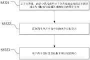
图12为本公开一些实施例提供的图9中步骤S512的流程图;FIG. 12 is a flowchart of step S512 in FIG. 9 provided by some embodiments of the present disclosure;
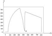
图13为本公开一些实施例提供的像素统计分布的示意图;13 is a schematic diagram of a statistical distribution of pixels provided by some embodiments of the present disclosure;
图14为本公开一些实施例提供的图8中步骤S53的流程图;FIG. 14 is a flowchart of step S53 in FIG. 8 provided by some embodiments of the present disclosure;
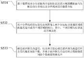
图15为本公开一些实施例提供的图14中步骤S532的流程图;FIG. 15 is a flowchart of step S532 in FIG. 14 provided by some embodiments of the present disclosure;
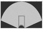
图16为本公开一些实施例提供的第三处理图像的示意图;16 is a schematic diagram of a third processed image provided by some embodiments of the present disclosure;
图17为本公开一些实施例提供的获取弧度的轮廓点集合的示意图;FIG. 17 is a schematic diagram of acquiring a set of contour points of radians provided by some embodiments of the present disclosure;
图18为本公开一些实施例提供的图8中步骤S54的流程图;FIG. 18 is a flowchart of step S54 in FIG. 8 provided by some embodiments of the present disclosure;
图19A为本公开的一些实施例提供的二维的超声图像的横断面示意图;19A is a schematic cross-sectional view of a two-dimensional ultrasound image provided by some embodiments of the present disclosure;
图19B为本公开的一些实施例提供的图19A中二维的超声图像对应的三维超声图像的示意图;19B is a schematic diagram of a three-dimensional ultrasound image corresponding to the two-dimensional ultrasound image in FIG. 19A according to some embodiments of the present disclosure;
图20为本公开一些实施例提供的穿刺导航系统的模块组成示意图;FIG. 20 is a schematic diagram of a module composition of a puncture navigation system provided by some embodiments of the present disclosure;
图21为本公开一些实施例提供的导航处理模块的组成示意图;21 is a schematic diagram of the composition of a navigation processing module provided by some embodiments of the present disclosure;
图22为本公开一些实施例提供的第二运动路径确定模块的组成示意图;22 is a schematic diagram of the composition of a second motion path determination module provided by some embodiments of the present disclosure;
图23为本公开一些实施例提供的坐标系转换单元的组成示意图;23 is a schematic diagram of the composition of a coordinate system conversion unit provided by some embodiments of the present disclosure;
图24为本公开另一些实施例提供的坐标系转换单元的组成示意图;24 is a schematic diagram of the composition of a coordinate system conversion unit provided by other embodiments of the present disclosure;
图25为本公开一些实施例提供的校正模块的组成示意图;25 is a schematic diagram of the composition of a calibration module provided by some embodiments of the present disclosure;
图26为本公开一些实施例提供的一种电子设备的框图。FIG. 26 is a block diagram of an electronic device provided by some embodiments of the present disclosure.
具体实施方式Detailed ways
下面将结合本公开实施例中的附图,对本公开实施例中的技术方案进行清楚、完整地描述,显然,所描述的实施例仅仅是本公开一部分实施例,而不是全部的实施例。基于本公开中的实施例,本领域普通技术人员在没有作出创造性劳动前提下所获得的所有其他实施例,都属于本公开保护的范围。The technical solutions in the embodiments of the present disclosure will be clearly and completely described below with reference to the accompanying drawings in the embodiments of the present disclosure. Obviously, the described embodiments are only a part of the embodiments of the present disclosure, but not all of the embodiments. Based on the embodiments in the present disclosure, all other embodiments obtained by those of ordinary skill in the art without creative efforts shall fall within the protection scope of the present disclosure.
除非另有定义,本公开实施例使用的所有术语(包括技术和科学术语)具有与本公开所属领域的普通技术人员共同理解的相同含义。还应当理解,诸如在通常字典里定义的那些术语应当被解释为具有与它们在相关技术的上下文中的含义相一致的含义,而不应用理想化或极度形式化的意义来解释,除非本公开实施例明确地这样定义。Unless otherwise defined, all terms (including technical and scientific terms) used in the embodiments of the present disclosure have the same meaning as commonly understood by one of ordinary skill in the art to which this disclosure belongs. It should also be understood that terms such as those defined in ordinary dictionaries should be construed as having meanings consistent with their meanings in the context of the related art, and should not be construed in an idealized or highly formalized sense unless the present disclosure Embodiments are explicitly defined as such.
本公开实施例中使用的“第一”、“第二”以及类似的词语并不表示任何顺序、数量或者重要性,而只是用来区分不同的组成部分。“一个”、“一”或者“该”等类似词语也不表示数量限制,而是表示存在至少一个。同样,“包括”或者“包含”等类似的词语意指出现该词前面的元件或者物件涵盖出现在该词后面列举的元件或者物件及其等同,而不排除其他元件或者物件。“连接”或者“相连”等类似的词语并非限定于物理的或者机械的连接,而是可以包括电性的连接,不管是直接的还是间接的。"First", "second" and similar words used in the embodiments of the present disclosure do not denote any order, quantity or importance, but are only used to distinguish different components. "A," "an," or "the" and the like also do not denote a limitation of quantity, but rather denote the presence of at least one. Likewise, words like "comprising" or "comprising" mean that the elements or things appearing before the word encompass the elements or things recited after the word and their equivalents, but do not exclude other elements or things. Words like "connected" or "connected" are not limited to physical or mechanical connections, but may include electrical connections, whether direct or indirect.
本公开中的目标组织是指器官或器官的一部分,例如,前列腺、肝脏、胰腺、心脏等,而病灶则位于目标组织内。The target tissue in the present disclosure refers to an organ or part of an organ, eg, prostate, liver, pancreas, heart, etc., and the lesion is located within the target tissue.
穿刺活检是骨与软组织肿瘤获取组织病理诊断的主要方法,例如对目标组织进行穿刺活检之后,可以获得病灶区域。然而目前一些导航系统都是借助于双目视觉定位装置,通过在穿刺针和超声探头上设置可进行光学定位的光学标记件,将穿刺针与肿瘤的三维位置关系进行实时显示。但是若采用这种方式,不仅需要双目视觉定位装置,还需要在穿刺针和超声探头上设置光学标记件,这样不仅费用较高,而且还使得超声探头和穿刺针的结构更加复杂,给操作者的操作带来极大的不便。Needle biopsy is the main method for obtaining histopathological diagnosis of bone and soft tissue tumors. For example, after needle biopsy of the target tissue, the lesion area can be obtained. However, some current navigation systems rely on binocular vision positioning devices to display the three-dimensional positional relationship between the puncture needle and the tumor in real time by arranging optical markers on the puncture needle and ultrasonic probe that can perform optical positioning. However, if this method is adopted, not only a binocular vision positioning device is required, but also an optical marker needs to be provided on the puncture needle and the ultrasonic probe, which is not only expensive, but also makes the structures of the ultrasonic probe and the puncture needle more complicated, which is difficult for operation. The operator's operation brings great inconvenience.
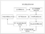
本公开至少一实施例提供了一种用于穿刺装置的穿刺导航系统,穿刺装置包括基座、穿刺针、超声探头和具有至少一个穿刺控制件的穿刺控制部。穿刺导航系统包括定位模块、超声图像获取模块、穿刺规划模块、坐标系转换模块、第一运动路径确定模块、第二运动路径确定模块和导航处理模块。定位模块配置为基于基座对穿刺针进行定位,确定穿刺针在空间坐标系内的第一三维坐标信息,空间坐标系是基于基座建立的坐标系。超声图像获取模块配置为获取超声探头采集的目标组织的一组超声图像,以确定一组超声图像对应的三维超声图像。穿刺规划模块配置为基于三维超声图像进行用于穿刺针的穿刺规划,以确定穿刺规划信息,其中,穿刺规划信息包括穿刺针的进针点位置、穿刺针的进针方向和穿刺针的目标穿刺点位置。坐标系转换模块配置为建立超声图像的图像坐标系与空间坐标系之间的转换关系,使得基于转换关系确定第一三维坐标信息在图像坐标系内的实时图像位置,以实时地在图像坐标系中可视化穿刺针与目标穿刺点位置之间的相对位置。第一运动路径确定模块配置为在图像坐标系中,基于穿刺针与目标穿刺点位置之间的相对位置确定穿刺针的第一运动路径。第二运动路径确定模块配置为基于图像坐标系内的第一运动路径确定与穿刺针具有一预定位置关系的穿刺导向件在空间坐标系内的第二运动路径。导航处理模块配置为在空间坐标系中,基于第二运动路径,通过至少一个穿刺控制件进行穿刺针的导航。之后基于第二运动路径进行穿刺针的导航,对目标组织进行穿刺活检之后,可以获得病灶区域。At least one embodiment of the present disclosure provides a puncture navigation system for a puncture device. The puncture device includes a base, a puncture needle, an ultrasonic probe, and a puncture control portion having at least one puncture control member. The puncture navigation system includes a positioning module, an ultrasonic image acquisition module, a puncture planning module, a coordinate system conversion module, a first motion path determination module, a second motion path determination module and a navigation processing module. The positioning module is configured to position the puncture needle based on the base, and determine the first three-dimensional coordinate information of the puncture needle in a space coordinate system, and the space coordinate system is a coordinate system established based on the base. The ultrasound image acquisition module is configured to acquire a set of ultrasound images of the target tissue acquired by the ultrasound probe, so as to determine a three-dimensional ultrasound image corresponding to the set of ultrasound images. The puncture planning module is configured to perform puncture planning for the puncture needle based on the three-dimensional ultrasound image to determine puncture planning information, wherein the puncture planning information includes the position of the needle insertion point of the puncture needle, the needle insertion direction of the puncture needle and the target puncture of the puncture needle point location. The coordinate system conversion module is configured to establish a conversion relationship between the image coordinate system of the ultrasound image and the space coordinate system, so that the real-time image position of the first three-dimensional coordinate information in the image coordinate system is determined based on the conversion relationship, so that the real-time image coordinate system can be converted into the image coordinate system in real time. Visualize the relative position between the puncture needle and the target puncture site location. The first motion path determination module is configured to determine the first motion path of the puncture needle based on the relative position between the puncture needle and the target puncture point position in the image coordinate system. The second motion path determination module is configured to determine a second motion path of the puncture guide having a predetermined positional relationship with the puncture needle in the space coordinate system based on the first motion path in the image coordinate system. The navigation processing module is configured to navigate the puncture needle through the at least one puncture control member based on the second motion path in the space coordinate system. Then, the puncture needle is navigated based on the second movement path, and after the target tissue is subjected to a puncture biopsy, the lesion area can be obtained.
本公开至少一实施例还提供了一种对应于上述穿刺导航系统的穿刺导航方法,穿刺导航方法包括:建立空间坐标系,空间坐标系是基于基座建立的坐标系;基于基座确定穿刺针在空间坐标系内的第一三维坐标信息;获取超声探头采集的目标组织的一组超声图像,以确定一组超声图像对应的三维超声图像;基于三维超声图像进行用于穿刺针的穿刺规划,以确定穿刺规划信息,其中,穿刺规划信息包括穿刺针的进针点位置、穿刺针的进针方向和穿刺针的目标穿刺点位置;建立超声图像的图像坐标系与空间坐标系之间的转换关系,使得基于转换关系确定第一三维坐标信息在图像坐标系内的实时图像位置,以实时地在图像坐标系中可视化穿刺针与目标穿刺点位置之间的相对位置;在图像坐标系中,基于穿刺针与目标穿刺点位置之间的相对位置确定穿刺针的第一运动路径;基于图像坐标系内的第一运动路径确定与穿刺针具有一预定位置关系的穿刺导向件在空间坐标系内的第二运动路径;在空间坐标系中,基于第二运动路径,通过至少一个穿刺控制件进行穿刺针的导航。At least one embodiment of the present disclosure also provides a puncture navigation method corresponding to the above-mentioned puncture navigation system. The puncture navigation method includes: establishing a space coordinate system, where the space coordinate system is a coordinate system established based on a base; determining a puncture needle based on the base The first three-dimensional coordinate information in the space coordinate system; obtain a set of ultrasound images of the target tissue collected by the ultrasound probe to determine the three-dimensional ultrasound image corresponding to the set of ultrasound images; perform puncture planning for the puncture needle based on the three-dimensional ultrasound images, Determine the puncture planning information, wherein the puncture planning information includes the needle insertion point position of the puncture needle, the needle insertion direction of the puncture needle and the target puncture point position of the puncture needle; establish the transformation between the image coordinate system and the space coordinate system of the ultrasound image relationship, so that the real-time image position of the first three-dimensional coordinate information in the image coordinate system is determined based on the conversion relationship, so as to visualize the relative position between the puncture needle and the target puncture point position in the image coordinate system in real time; in the image coordinate system, The first motion path of the puncture needle is determined based on the relative position between the puncture needle and the target puncture point; based on the first motion path in the image coordinate system, the puncture guide having a predetermined positional relationship with the puncture needle is determined in the space coordinate system the second movement path of the puncture needle; in the space coordinate system, based on the second movement path, the puncture needle is navigated through at least one puncture control member.
本公开的实施例的穿刺导航系统或方法适用于各种具有穿刺主体与超声探头的穿刺装置的导航,在不采用双目视觉定位装置,也不在穿刺针和超声探头上设置光学标记件的情况下,可以实现实时获取并可视化穿刺针与目标穿刺点之间的位置关系,从而能够节省成本,也能降低超声和穿刺针结构的复杂度,便于操作者操作。The puncture navigation system or method of the embodiments of the present disclosure is suitable for the navigation of various puncture devices having a puncture body and an ultrasonic probe, without the use of a binocular vision positioning device or the provision of optical markers on the puncture needle and the ultrasonic probe. In this way, the positional relationship between the puncture needle and the target puncture point can be obtained and visualized in real time, thereby saving costs, reducing the complexity of the ultrasound and the puncture needle structure, and facilitating the operation of the operator.
下面结合附图对本公开的实施例及其示例进行详细说明。The embodiments of the present disclosure and examples thereof will be described in detail below with reference to the accompanying drawings.
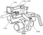
图1A-图1B为本公开一些实施例提供的穿刺装置的结构示意图。图2为本公开一些实施例提供的穿刺装置的局部结构示意图。1A-1B are schematic structural diagrams of a puncture device according to some embodiments of the present disclosure. FIG. 2 is a partial structural schematic diagram of a puncture device provided by some embodiments of the present disclosure.
本公开至少一实施例提供的穿刺装置包括基座、穿刺针、超声探头和穿刺控制部。为了本公开的说明清楚且简明,下文以图1A、图1B和图2示意的穿刺装置为例进行说明,但是本公开的导航系统和导航方法对适用的穿刺装置的结构或构造等并不作限制。A puncture device provided by at least one embodiment of the present disclosure includes a base, a puncture needle, an ultrasonic probe, and a puncture control portion. For the sake of clarity and conciseness in the description of the present disclosure, the puncture device shown in FIGS. 1A , 1B and 2 is used as an example for description below, but the navigation system and navigation method of the present disclosure do not limit the structure or structure of the applicable puncture device. .
例如,如图1A和图1B所示,穿刺装置1000可包括超声组件1100、穿刺针1200和穿刺控制部,通过超声组件1100获取超声图像,以便于指导穿刺针1200在穿刺控制部的控制作用下进行穿刺定位并穿刺到预定深度,以实现对穿刺针1200的导航,从而实现对目标组织的穿刺活检。For example, as shown in FIG. 1A and FIG. 1B , the
在一些示例中,穿刺控制部可包括至少一个穿刺控制件,例如,穿刺控制部可包括一个穿刺控制件、两个穿刺控制件或更多个穿刺控制件等。例如,当穿刺控制部包括两个以上的穿刺控制件时,穿刺控制件彼此之间可具有联动关系,以便更灵活地对穿刺针1200进行导航。当然,本公开的实施例不仅限于此,穿刺控制件彼此之间也可以不具有联动关系,只要能够实现对穿刺针1200的导航即可,本公开的实施例对此不作限制。In some examples, the penetration control may include at least one penetration control, eg, the penetration control may include one penetration control, two penetration controls, or more penetration controls, and the like. For example, when the puncture control part includes more than two puncture control members, the puncture control members may have a linkage relationship with each other, so as to navigate the
在一些示例中,穿刺控制部的至少一个穿刺控制件中的每个被配置为与驱动机构连接并由驱动机构直接驱动运动,以实现对穿刺针1200的导航。In some examples, each of the at least one puncture control member of the puncture control portion is configured to be connected to and directly driven for movement by a drive mechanism to enable navigation of the
本公开的实施例对穿刺控制部的穿刺控制件和穿刺针1200之间的连接或相对位置关系不作限制,例如穿刺控制件可以与穿刺针1200连接,也可以不连接,例如穿刺针1200可以位于穿刺控制件之上,也可以不位于穿刺控制件之上,具体可以根据实际情况进行自由调整,只要能够实现穿刺针1200的穿刺定位和穿刺深度控制即可,本公开的实施例不再穷举和赘述。The embodiments of the present disclosure do not limit the connection or relative positional relationship between the puncture control member of the puncture control portion and the
在一些示例中,如图1A、图1B和图2所示,穿刺装置1000还可包括穿刺导向释放机构1300和穿刺定位臂组1600。In some examples, as shown in FIGS. 1A , 1B and 2 , the
例如,穿刺导向释放机构1300包括穿刺针导向支臂1310和位于穿刺针导向支臂1310侧部的开合瓣1320,开合瓣1320闭合时具有供穿刺针1200通过的过孔1330。穿刺针导向支臂1310包括导向器械盒1360,开合瓣1320设置在导向器械盒1360上。穿刺定位臂组1600被配置为响应于控制信号将穿刺针导向支臂1310移动至穿刺位置。穿刺导向释放机构1300还可包括穿刺深度控制挡板1340,穿刺深度控制挡板1340例如通过滑槽等滑动机构沿穿刺针导向支臂1310的轴向滑动设置在穿刺针导向支臂1310侧部,穿刺深度控制挡板1340上具有供穿刺针1200通过的非闭合定位孔1350。穿刺深度控制挡板1340设置在开合瓣1320的后方,穿刺深度控制挡板1340的非闭合定位孔1350与开合瓣1320闭合形成的过孔1330相对。For example, the puncture
在一些示例中,穿刺装置1000还可包括穿刺板1400。穿刺板1400可以使得穿刺针1200在体外固定,通过在体外固定穿刺针1200,提高了针体的稳定性,进而可以提高手术质量。In some examples, piercing
例如,超声组件1100包括超声探头和探头控制组件,探头控制组件被配置为控制超声探头的探测位置及探测方向,从而使得超声探头获取超声图像。For example, the
在一些示例中,通过超声探头获取超声图像,并基于超声图像,控制穿刺定位臂组1600进行穿刺定位,将穿刺针导向支臂1310移动至穿刺位置,而且还控制穿刺深度控制挡板1340滑动到相应位置。此时,开合瓣1320闭合形成过孔1330,将穿刺针1200与穿刺深度控制挡板1340的非闭合定位孔1350的侧壁贴合并从过孔1330中穿出,经由穿刺板1400,插入到目标穿刺点。In some examples, an ultrasound image is acquired through an ultrasound probe, and based on the ultrasound image, the puncture
在一些示例中,由于穿刺深度控制挡板1340的非闭合定位孔1350和穿刺针的针尖之间的相对位置固定,例如穿刺针的针尖的目标穿刺点位置减去穿刺针1200的穿刺针实际物理规格可得到非闭合定位孔1350需要到达的目标终点位置,因此,本公开一些实施例通过将非闭合定位孔1350从起始位置移带动到终点位置并将穿刺针1200与穿刺深度控制挡板1340的非闭合定位孔1350的侧壁贴合并从过孔1330中穿出,沿着导向器械盒1360的方向进行穿刺,从而可使穿刺针1200的针尖插入到目标穿刺点。In some examples, since the relative position between the
在一些示例中,穿刺控制部的至少一个穿刺控制件包括穿刺定位臂组1600和穿刺深度控制挡板1340。In some examples, the at least one piercing control member of the piercing control portion includes a piercing
例如,穿刺定位臂组1600与对应的驱动机构连接,使得穿刺定位臂组1600被驱动机构驱动,从而带动穿刺针导向支臂1310移动至穿刺位置。例如,穿刺深度控制挡板1340与对应的驱动机构连接,使得穿刺深度控制挡板1340被控制滑动到相应位置。For example, the puncture
在一些示例中,穿刺定位臂组1600可以为连杆机构,此时穿刺定位臂组1600的一部分(记为第一部分)可与驱动机构连接而被直接驱动运动,且穿刺定位臂组1600的另一部分(记为第二部分)不由驱动机构直接驱动连接而由穿刺定位臂组1600的第一部分的运动被带动运动。如此,穿刺控制部的穿刺控制件包括穿刺定位臂组1600的第一部分。当然,此仅仅为示例性的,并不为本公开的限制,可以根据穿刺装置的具体结构形式的穿刺定位臂组1600的结构而定,此处不再赘述。In some examples, the puncture
在一些示例中,穿刺装置1000还可包括基座1500,用于支撑穿刺装置主体。穿刺定位臂组1600设置在基座1500上。超声组件1100设置在基座1500上。例如,超声探头可移动地设置在基座1500上。例如,穿刺定位臂组1600的固定端活动连接在基座1500上。In some examples, the piercing
在一些示例中,超声组件1100的探头控制组件包括超声进给平台1110和超声回转平台(未图示),超声进给平台1110可以使得超声探头沿该超声探头的轴向移动,超声回转平台可以使得超声探头沿该超声探头的轴线转动,由此可控制超声探头的深度和角度。In some examples, the probe control assembly of the
在一些示例中,穿刺控制部的至少一个穿刺控制件为三个穿刺控制件,这三个穿刺控制件中的两个穿刺控制件为穿刺定位臂组1600中的两个穿刺控制件(例如记为第一穿刺控制件和第二穿刺控制件)且第三个穿刺控制件即为穿刺深度控制挡板1340。例如,这三个穿刺控制件中的第一穿刺控制件和第二穿刺控制件分别为:通过一个转轴与基座1500进行活动连接的一个穿刺定位臂,以及基于该转轴可转动的另一个传动杆。此仅仅为示例性的,并不为本公开的限制,有关穿刺定位臂组1600中具有的穿刺控制件的个数和构造等可以根据实际情况进行自由调整,由于此不为本公开需要描述的重点,此处不再赘述。In some examples, at least one puncture control member of the puncture control portion is three puncture control members, and two puncture control members of the three puncture control members are two puncture control members in the puncture positioning arm set 1600 (for example, marked are the first puncture control member and the second puncture control member) and the third puncture control member is the puncture
需要说明的是,为了本公开的说明清楚且简明,本文主要以图1A、图1B和图2示意的穿刺装置为例进行说明,但是本公开的导航系统和导航方法对适用的穿刺装置的结构或构造等并不作限制,其还可适用于其他结构或构造设计的具有基座、穿刺针、穿刺控制部和超声探头的穿刺装置。还需要说明的是,鉴于穿刺装置的具体结构并不为本公开需要描述的重点内容,在此不做赘述。It should be noted that, for the sake of clarity and conciseness of the description of the present disclosure, the puncture device illustrated in FIG. 1A , FIG. 1B and FIG. 2 is mainly used as an example for description, but the navigation system and the navigation method of the present disclosure are applicable to the structure of the puncture device. or the structure is not limited, and it is also applicable to a puncture device with a base, a puncture needle, a puncture control part and an ultrasonic probe with other structures or structural designs. It should also be noted that, since the specific structure of the puncturing device is not the key content to be described in the present disclosure, it will not be repeated here.
图3为本公开一些实施例提供的穿刺导航方法的流程图。FIG. 3 is a flowchart of a puncture navigation method provided by some embodiments of the present disclosure.
例如,如图3所示,本公开至少一实施例提供的用于穿刺装置的穿刺导航方法包括步骤S1至步骤S6。For example, as shown in FIG. 3 , a puncture navigation method for a puncture device provided by at least one embodiment of the present disclosure includes steps S1 to S6 .
步骤S1、建立空间坐标系,其中,该空间坐标系可以是基于基座1500建立的,例如基于基座1500建立的世界坐标系。Step S1 , establishing a space coordinate system, wherein the space coordinate system may be established based on the
步骤S2、基于基座1500确定穿刺针1200在空间坐标系内的第一三维坐标信息。Step S2 , determining the first three-dimensional coordinate information of the
步骤S3、获取超声探头采集的目标组织的一组超声图像,以确定这一组超声图像对应的三维超声图像。Step S3: Acquire a group of ultrasonic images of the target tissue collected by the ultrasonic probe to determine a three-dimensional ultrasonic image corresponding to the group of ultrasonic images.
步骤S4、基于三维超声图像进行用于穿刺针1200的穿刺规划,以确定穿刺规划信息,其中,穿刺规划信息包括穿刺针1200的进针点位置、穿刺针1200的进针方向和穿刺针1200的目标穿刺点位置。Step S4: Perform a puncture plan for the
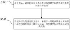
步骤S5、建立超声图像的图像坐标系与空间坐标系之间的转换关系,以使得基于图像坐标系与空间坐标系之间的转换关系确定第一三维坐标信息在图像坐标系内的实时图像位置,以实时地在图像坐标系中可视化穿刺针1200与目标穿刺点位置之间的相对位置。Step S5, establishing the transformation relationship between the image coordinate system of the ultrasound image and the space coordinate system, so that the real-time image position of the first three-dimensional coordinate information in the image coordinate system is determined based on the transformation relationship between the image coordinate system and the space coordinate system , to visualize the relative position between the
步骤S6、在图像坐标系中,基于穿刺针1200与目标穿刺点位置之间的相对位置确定穿刺针1200的第一运动路径。Step S6, in the image coordinate system, determine the first movement path of the
步骤S7、基于图像坐标系内的第一运动路径确定与穿刺针1200具有一预定位置关系的穿刺导向件(例如穿刺导向为穿刺深度控制挡板1340的非闭合定位孔1350,具体可见下文)在空间坐标系内的第二运动路径。Step S7: Determine the puncture guide that has a predetermined positional relationship with the
步骤S8、在空间坐标系中,基于穿刺导向件的第二运动路径,通过至少一个穿刺控制件进行穿刺针1200的导航。Step S8, in the space coordinate system, based on the second movement path of the puncture guide, the
本公开的实施例的穿刺导航方法在不采用双目视觉定位装置,也不在穿刺针和超声探头上设置光学标记件的情况下,可以实时获取穿刺针与目标穿刺点之间的相对位置关系,从而能够节省成本,也能降低超声和穿刺针结构的复杂度,便于操作者操作。The puncture navigation method of the embodiment of the present disclosure can obtain the relative positional relationship between the puncture needle and the target puncture point in real time without using a binocular vision positioning device and without setting optical markers on the puncture needle and the ultrasonic probe. Therefore, the cost can be saved, and the complexity of the ultrasonic wave and the puncture needle structure can also be reduced, which is convenient for the operator to operate.
本公开的实施例通过将穿刺针从空间坐标系转换至图像坐标系,使得能将穿刺针与目标穿刺点之间的相对位置进行可视化,直观地向用于展示,而且本公开的实施例通过直观展示来对穿刺导航进行自动补偿,有利于提升穿刺导航的精准度,实现更精准治疗。In the embodiment of the present disclosure, by converting the puncture needle from the space coordinate system to the image coordinate system, the relative position between the puncture needle and the target puncture point can be visualized and displayed intuitively. Intuitive display to automatically compensate for puncture navigation, which is beneficial to improve the accuracy of puncture navigation and achieve more precise treatment.
本公开的实施例基于坐标系转换和图像穿刺规划,能够巧妙地实现穿刺针的导航,易于达到预期效果,操作简便,避免额外成本的增加。Based on coordinate system transformation and image puncture planning, the embodiments of the present disclosure can subtly realize the navigation of the puncture needle, easily achieve the expected effect, and operate easily, and avoid the increase of extra cost.
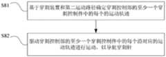
图4为本公开一些实施例提供的图3中步骤S8的流程图。FIG. 4 is a flowchart of step S8 in FIG. 3 provided by some embodiments of the present disclosure.
例如,如图4所示,步骤S8包括步骤S81至步骤S82。For example, as shown in FIG. 4, step S8 includes steps S81 to S82.
步骤S81、基于穿刺装置1000和第二运动路径确定穿刺控制部的至少一个穿刺控制件中的每个的运动轨迹。Step S81 , determining the motion trajectory of each of the at least one puncture control member of the puncture control portion based on the
步骤S82、驱动穿刺控制部的至少一个穿刺控制件中的每个沿对应的运动轨迹进行运动,以导航穿刺针1200。Step S82 , driving each of the at least one puncture control member of the puncture control unit to move along a corresponding movement track, so as to navigate the
本公开的实施例的穿刺导航方法根据穿刺针与目标穿刺点之间的相对位置来确定所选择的穿刺导向件对应的第二运动路径,从而确定穿刺装置中需要运动的各个部件的运动轨迹以实现穿刺导航,这样可使适用的穿刺装置的范围更广,操作简便,成本低。The puncture navigation method of the embodiment of the present disclosure determines the second motion path corresponding to the selected puncture guide according to the relative position between the puncture needle and the target puncture point, so as to determine the motion trajectory of each component that needs to be moved in the puncture device to The puncture navigation is realized, so that the applicable puncture device has a wider range, the operation is simple and the cost is low.
例如,为了表述清楚与方便,将步骤S1中的穿刺装置1000的基座1500上的其中一点的坐标信息记为(0,0,0),步骤S2中的第一三维坐标信息记为(x1,y1,z1)。For example, for the sake of clarity and convenience, the coordinate information of one point on the
在一些示例中,穿刺针1200的第一三维坐标信息(x1,y1,z1)包括穿刺针1200的针尖在空间坐标系内的三维坐标信息。由此,穿刺针1200的第一运动路径包括穿刺针1200的针尖的第一运动路径。本公开的实施例利用穿刺针的针尖来定位穿刺针的三维坐标信息,由于穿刺针的针尖的位置容易获取,使得穿刺针的三维坐标信息也易于获取,从而有利于穿刺针的导航的实现。In some examples, the first three-dimensional coordinate information (x1, y1, z1) of the
在一些示例中,穿刺针的第一三维坐标信息在图像坐标系内的实时图像位置可视为一个起始位置,目标穿刺点位置可视为一个对应起始位置的目标终点位置,从而可以根据起始位置和目标终点位置在图像坐标系内确定穿刺针在起始位置和目标终点位置之间的运动路径规划。In some examples, the real-time image position of the first three-dimensional coordinate information of the puncture needle in the image coordinate system may be regarded as a starting position, and the position of the target puncture point may be regarded as a target end position corresponding to the starting position, so that the The start position and the target end position determine the motion path planning of the puncture needle between the start position and the target end position in the image coordinate system.
在一些示例中,步骤S2可以在步骤S3之前执行,也可以在步骤S3之后执行,步骤S2和步骤S3也可以同时执行,本公开的实施例对两者执行的先后顺序不作限制。In some examples, step S2 may be performed before step S3 or after step S3, and step S2 and step S3 may also be performed at the same time, and the embodiment of the present disclosure does not limit the order of execution of the two.
现根据图5-图18来对本公开实施例中的穿刺导向件为非闭合定位孔1350的情况下的穿刺导航方法进行非限制性说明。5-18, a non-limiting description of the puncture navigation method in the case where the puncture guide is the
图5为本公开一些实施例提供的图3中步骤S7的流程图FIG. 5 is a flowchart of step S7 in FIG. 3 provided by some embodiments of the present disclosure
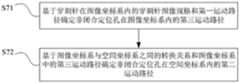
例如,如图5所示,响应于穿刺导向件为非闭合定位孔1350,步骤S7包括步骤S71至步骤S72。For example, as shown in FIG. 5 , in response to the puncture guide being the
步骤S71、基于穿刺针1200在图像坐标系内的穿刺针图像规格和第一运动路径确定非闭合定位孔1350在图像坐标系内的第三运动路径。Step S71 , determining a third motion path of the
步骤S72、基于图像坐标系与空间坐标系之间的转换关系和图像坐标系中的第三运动路径确定非闭合定位孔1350在空间坐标系内的第二运动路径。Step S72 , determining the second movement path of the
本公开的实施例可以根据穿刺装置中作为确定量的非闭合定位孔来确定用于指导穿刺针进行导航的运动路径,导航求解简单方便,适用范围广泛,有利于穿刺针的导航的实现。The embodiments of the present disclosure can determine the movement path for guiding the puncture needle to navigate according to the non-closed positioning hole in the puncture device, which is simple and convenient to solve, has a wide range of applications, and is beneficial to the realization of the puncture needle navigation.
在一些示例中,对于步骤S7,穿刺导向件可以是穿刺深度控制挡板1340的非闭合定位孔1350,但是本公开的实施例的穿刺导向件不仅限于此,例如其还可以是穿刺针导向支臂1310或者过孔1330或者穿刺导向释放机构1300上其他用于穿刺导向的合适位置,只要是与穿刺针1200具有一个确定的相对位置关系的合理位置即可,这里不再赘述。为了本文的清楚与简洁,下文主要以穿刺导向件为穿刺深度控制挡板1340的非闭合定位孔1350为例进行说明。In some examples, for step S7, the puncture guide may be the
在一些示例中,穿刺导航方法的步骤S2包括以下过程或步骤:根据非闭合定位孔1350在空间坐标系内的三维坐标信息和穿刺针1200在空间坐标系内的针规格(即穿刺针实际物理规格)确定穿刺针1200的第一三维坐标信息,使得第一三维坐标信息包括穿刺针1200在空间坐标系内的三维坐标信息。例如,穿刺针1200在空间坐标系内的针规格可记为穿刺针实际物理规格。In some examples, step S2 of the puncture navigation method includes the following process or steps: according to the three-dimensional coordinate information of the
在一些示例中,穿刺针1200的穿刺针实际物理规格包括针的裸露长度,穿刺针实际物理规格可以表示穿刺针1200在空间坐标系下的实际物理尺寸。穿刺针图像规格表示穿刺针1200在图像坐标系下的图像尺寸,该图像尺寸是基于穿刺针的穿刺针实际物理规格映射到图像坐标系得到的一种规格,例如穿刺针的穿刺针实际物理规格按照图像分辨率向图像坐标系进行映射,以确定出穿刺针图像规格。In some examples, the actual physical specification of the
本公开的实施例可以根据穿刺装置中作为确定量的非闭合定位孔来确定穿刺针的三维坐标信息,使得穿刺针的三维坐标信息精确并易于获取,从而有利于穿刺针的导航的实现,适用范围广泛。The embodiments of the present disclosure can determine the three-dimensional coordinate information of the puncture needle according to the non-closed positioning hole in the puncture device as a certain amount, so that the three-dimensional coordinate information of the puncture needle is accurate and easy to obtain, thereby facilitating the realization of the navigation of the puncture needle. Wide range.
在一些示例中,穿刺导航方法还包括以下过程或步骤:实时地可视化以下的至少一种:超声图像、三维超声图像、穿刺针1200的针尖、穿刺针1200的针尖与目标穿刺点位置之间的相对位置、穿刺针1200的第一运动路径。In some examples, the puncture navigation method further includes the process or step of visualizing, in real time, at least one of: an ultrasound image, a three-dimensional ultrasound image, the tip of the
本公开的实施例能够将超声有关图像以及穿刺针与目标穿刺点之间的相对位置等进行可视化,直观地向用于实时展示,能够方便、准确地实时监测穿刺针的导航情况,对穿刺导航具有一定的指导作用。The embodiments of the present disclosure can visualize the relevant ultrasound images and the relative position between the puncture needle and the target puncture point, etc., and display them intuitively in real time. It can conveniently and accurately monitor the navigation of the puncture needle in real time. has a certain guiding role.
图6为本公开一些实施例提供的超声图像的原始图像的示意图。FIG. 6 is a schematic diagram of an original image of an ultrasound image provided by some embodiments of the present disclosure.
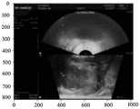
例如,在步骤S3中,获取的一组超声图像包括多张超声图像。例如,如图6所示,每张超声图像均为二维的图像。例如,超声图像包括待分割的病灶区域。For example, in step S3, the acquired set of ultrasound images includes a plurality of ultrasound images. For example, as shown in FIG. 6 , each ultrasound image is a two-dimensional image. For example, the ultrasound image includes the lesion area to be segmented.
在一些示例中,在步骤S3中,本公开的实施例根据所采集前列腺的尖部和底部位置信息,控制超声探头从尖部到底部以固定采集间距进行运动,并截取每个间距的前列腺图像,完成二维的超声图像的采集任务。In some examples, in step S3, the embodiment of the present disclosure controls the ultrasound probe to move from the tip to the bottom at a fixed acquisition interval according to the acquired position information of the tip and bottom of the prostate, and captures images of the prostate at each interval , to complete the acquisition of two-dimensional ultrasound images.
在一些示例中,在步骤S3中,本公开的实施例通过将获取的二维的超声图像进行前列腺外轮廓勾画(例如包括病灶轮廓与外轮廓),然后基于图像坐标系进行三维重建,得到三维超声图像。In some examples, in step S3, the embodiment of the present disclosure obtains a three-dimensional image by delineating the outer contour of the prostate (for example, including the lesion contour and the outer contour) on the acquired two-dimensional ultrasound image, and then performing three-dimensional reconstruction based on the image coordinate system. Ultrasound image.
例如,在步骤S4中,目标穿刺点位置是指需要穿刺到达的目标穿刺位置,其可以根据目标组织的病灶区域的具体情况而定。例如,在步骤S5中,实时图像位置是指穿刺针1200的第一三维坐标信息通过图像坐标系与空间坐标系之间的转换关系对应到图像坐标系中的实时位置。For example, in step S4, the target puncture point position refers to the target puncture position to be reached by puncturing, which may be determined according to the specific conditions of the lesion area of the target tissue. For example, in step S5, the real-time image position means that the first three-dimensional coordinate information of the
为了本文的清楚、简洁,本文主要是以用于前列腺的穿刺装置和前列腺超声图像为例进行说明,例如图6所示为前列腺超声图像,但是本公开对适用的穿刺部位并不作限制,还可适用于其他需要实现穿刺的导航的应用场景,本公开对此不做赘述。For the sake of clarity and brevity, this article mainly takes the puncture device for the prostate and the prostate ultrasound image as an example for description. For example, FIG. 6 shows the prostate ultrasound image. However, the present disclosure does not limit the applicable puncture site. It is applicable to other application scenarios that need to implement puncture navigation, which will not be described in detail in this disclosure.
例如,在步骤S61中,第二运动路径是矢量路径,例如非闭合定位孔1350在空间坐标系内的第二运动路径表示非闭合定位孔1350在穿刺控制部夹持下运动到在规划下需要运动到达的目标空间位置而形成的动作的空间特征,例如非闭合定位孔1350的第二运动路径中的每个点包括位置和姿态等信息。For example, in step S61, the second movement path is a vector path, for example, the second movement path of the
图7为本公开一些实施例提供的非闭合定位孔在空间坐标系内的第二运动路径的原理示意图。FIG. 7 is a schematic schematic diagram of the second movement path of the non-closed positioning hole in the space coordinate system provided by some embodiments of the present disclosure.
例如,如图7所示,黑色实心的圆点O1表示穿刺深度控制挡板1340的非闭合定位孔1350在空间坐标系下的起始位置,即第二运动路径的起始位置;非实心的圆点O2表示穿刺深度控制挡板1340的非闭合定位孔1350在空间坐标系下的目标终点位置,即第二运动路径的目标终点位置。从圆点O1运动到圆点O2之间的运动路径为非闭合定位孔1350在空间坐标系下的第二运动路径,其可以是直线,也可以是曲线,具体可以视实际情况而定。因此,在非闭合定位孔1350从圆点O1运动到圆点O2之后,将穿刺针1200与穿刺深度控制挡板1340的非闭合定位孔1350的侧壁贴合并从过孔1330中穿出,经由穿刺板1400,使得穿刺针1200的针尖插入到空间坐标系下的目标穿刺点。For example, as shown in FIG. 7 , the solid black dot O1 represents the starting position of the
在一些示例中,本公开的实施例可以将基座1500的中心作为空间坐标系的原点(0,0,0),此时,可将基座1500的水平方向作为空间坐标系的横轴、将基座1500的竖直方向作为空间坐标系的竖轴、将与超声组件1100的前进方向作为空间坐标系的纵轴,以此来建立空间坐标系。又例如,可以将基座1500上的与穿刺控制件进行连接的位置处作为空间坐标系的原点(0,0,0),此时空间坐标系的横轴、竖轴、以及纵轴的方向可以与前一示例类似,在此不再赘述。当然,此仅仅为示例性的,并不为本公开的限制,只要是基座1500任一合理的点均可,这里不再赘述。In some examples, the embodiment of the present disclosure may use the center of the base 1500 as the origin (0, 0, 0) of the space coordinate system, and at this time, the horizontal direction of the
在一些示例中,穿刺定位臂组1600的固定端活动连接在基座1500上,基座1500上与穿刺定位臂组1600活动连接的位置记为基座连接处,如此,穿刺定位臂组1600(例如穿刺定位臂组1600可以为连杆机构)的运动都可基于基座1500的基座连接处进行计算,由于在基座1500上选定用于作为空间坐标系的原点与基座连接处的位置相对固定,则基于基座1500建立的空间坐标系与穿刺定位臂组1600之间的位置相对固定,因此,穿刺定位臂组1600的运动也可基于空间坐标系进行计算。例如,将基座1500上的基座连接处作为原点建立空间坐标系,如此,空间坐标系的原点可与穿刺定位臂组1600与基座1500活动连接的位置基座连接处重合,这样有利于简化穿刺控制件的运动轨迹的计算。In some examples, the fixed end of the puncture
在一些示例中,本公开的实施例通过机器人运动学原理实现基于穿刺装置的具体结构和非闭合定位孔1350的第二运动路径来反解每个穿刺控制件的运动轨迹(具体可见下文),这样可适用于任何结构组成的穿刺装置,普适性强。In some examples, the embodiments of the present disclosure implement the inverse solution of the motion trajectory of each puncture control member based on the specific structure of the puncture device and the second motion path of the
例如,在步骤S82中,穿刺装置1000的每个穿刺控制件分别连接一套驱动机构以使穿刺控制件沿着对应的运动轨迹进行运动。这样可使导航系统的驱动机制复杂度较低,操作简单方便。例如,驱动机构是由驱动器、直流电机和减速器主要构成,此仅仅为示例性的,并不为本公开的限制,只要能驱动对应穿刺控制件运动即可,这里不再赘述。For example, in step S82, each puncture control member of the
在一些示例中,本公开的实施例的穿刺控制件是指穿刺装置中的与驱动机构连接并被直接驱动的部件,对于穿刺装置中不由驱动机构直接驱动的部件,在反解至少一个穿刺控制件中的每个的运动轨迹的算法中已将耦合关系解耦,从而可以直接获取每个穿刺控制件的运动轨迹。需要说明的是,由于本公开的实施例对适用的穿刺装置的结构不作限制,本公开的实施例中的与驱动机构相连而被直接驱动运动的穿刺控制件和不与驱动机构连接而直接驱动运动的其他部件的具体划分可以根据实际情况进行自由调整,这里不再赘述。In some examples, the puncture control member of the embodiments of the present disclosure refers to a component in the puncture device that is connected to the driving mechanism and is directly driven. The coupling relationship has been decoupled in the algorithm of the motion trajectory of each of the components, so that the motion trajectory of each puncture control component can be directly obtained. It should be noted that, since the embodiments of the present disclosure do not limit the structure of the applicable puncture device, the puncture control member that is connected to the driving mechanism and is directly driven to move in the embodiments of the present disclosure is not connected to the driving mechanism and is directly driven. The specific division of other moving parts can be freely adjusted according to the actual situation, which will not be repeated here.
在一些示例中,穿刺导航方法还包括以下步骤或过程:基于基座1500对超声探头进行定位,确定超声探头在空间坐标系内的第二三维坐标信息。这样方便获取图像坐标系与空间坐标系之间的转换关系,从而确定在空间坐标系下穿刺针与目标穿刺点之间的相对位置。例如,为了描述的清楚与方便,可将第二三维坐标信息记为(x2,y2,z2),其体现超声探头和基座1500之间的实际物理位置关系。In some examples, the puncture navigation method further includes the following steps or processes: positioning the ultrasound probe based on the
在一些示例中,超声探头为较小尺寸的类圆柱结构,超声探头的第二三维坐标信息包括超声探头的中心在空间坐标系内的三维坐标信息。此仅仅为示例性的,并不为本公开的限制。In some examples, the ultrasonic probe is a cylindrical-like structure with a small size, and the second three-dimensional coordinate information of the ultrasonic probe includes three-dimensional coordinate information of the center of the ultrasonic probe in the space coordinate system. This is exemplary only and not limiting of the present disclosure.
例如,在步骤S5中,建立超声图像的图像坐标系与空间坐标系之间的转换关系包括以下步骤或过程:基于超声图像和超声探头的第二三维坐标信息(x2,y2,z2)将超声图像的图像坐标系转换至空间坐标系,以建立图像坐标系与空间坐标系之间的转换关系。For example, in step S5, establishing the transformation relationship between the image coordinate system of the ultrasound image and the space coordinate system includes the following steps or processes: converting the ultrasound image to the second three-dimensional coordinate information (x2, y2, z2) of the ultrasound image and the ultrasound probe The image coordinate system of the image is converted to the space coordinate system to establish the conversion relationship between the image coordinate system and the space coordinate system.
本公开的实施例通过坐标系转换实现了图像坐标系与空间坐标系之间的转换,使得在不采用双目视觉定位装置,也不在穿刺针和超声探头上设置光学标记件的情况下,能够简单、有效地在图像坐标系下实时确定穿刺针(例如穿刺针的针尖)与目标穿刺点位置之间的相对位置关系并进行可视化,从而实现穿刺针的导航,操作简便,可避免额外成本的增加。The embodiment of the present disclosure realizes the conversion between the image coordinate system and the space coordinate system through the coordinate system conversion, so that without using a binocular vision positioning device, nor setting an optical marker on the puncture needle and the ultrasonic probe, it is possible to Simple and effective real-time determination and visualization of the relative positional relationship between the puncture needle (such as the needle tip of the puncture needle) and the target puncture point under the image coordinate system, so as to realize the navigation of the puncture needle, which is easy to operate and can avoid additional costs. Increase.
例如,对于步骤S5,其在图像坐标系与空间坐标系之间的转换关系建立之后,可使空间坐标系中确定的第一三维坐标信息在已建立图像坐标系与空间坐标系之间的转换关系的基础上,实时地得到图像坐标系中对应的实时图像位置。For example, for step S5, after the conversion relationship between the image coordinate system and the space coordinate system is established, the first three-dimensional coordinate information determined in the space coordinate system can be converted between the established image coordinate system and the space coordinate system On the basis of the relationship, the corresponding real-time image position in the image coordinate system is obtained in real time.
图8为本公开一些实施例提供的图像坐标系转至空间坐标系的流程图。FIG. 8 is a flowchart of converting an image coordinate system to a space coordinate system according to some embodiments of the present disclosure.
例如,如图8所示,在一些示例中,对于基于超声图像和超声探头的第二三维坐标信息将超声图像的图像坐标系转换至空间坐标系,以建立图像坐标系与空间坐标系之间的转换关系,包括步骤S51至步骤S54。For example, as shown in FIG. 8 , in some examples, the image coordinate system of the ultrasound image is converted to the space coordinate system based on the second three-dimensional coordinate information of the ultrasound image and the ultrasound probe to establish a relationship between the image coordinate system and the space coordinate system. The conversion relationship includes steps S51 to S54.
步骤S51、对超声图像进行形态学图像处理,确定目标图像区域。Step S51 , perform morphological image processing on the ultrasound image to determine a target image area.
步骤S52、基于目标图像区域,获取像素统计分布。Step S52, based on the target image area, obtain the statistical distribution of pixels.
步骤S53、基于像素统计分布图以及预先确定的超声探头的直径,确定超声探头的直径与超声探头的直径所占用的像素间距个数之间的转换比率。Step S53: Determine the conversion ratio between the diameter of the ultrasonic probe and the number of pixel pitches occupied by the diameter of the ultrasonic probe based on the statistical distribution of pixels and the predetermined diameter of the ultrasonic probe.
步骤S54、基于转换比率和第二三维坐标信息,将图像坐标系转换至空间坐标系。Step S54: Convert the image coordinate system to a space coordinate system based on the conversion ratio and the second three-dimensional coordinate information.
本公开的实施例通过将图像特征提取和实际物理距离的信息结合来实现图像坐标系与空间坐标系的转换,操作难度较低,解算的复杂度低且准确度高,简单有效,具有很好的应用前景。The embodiment of the present disclosure realizes the conversion of the image coordinate system and the space coordinate system by combining the information of image feature extraction and actual physical distance, with low operation difficulty, low computational complexity and high accuracy, simple and effective, and has great advantages good application prospects.
在一些示例中,本公开的实施例基于图像坐标系与空间坐标系之间的转换关系既可以实现图像坐标系向空间坐标系转换,也可以实现空间坐标系向图像坐标系转换。In some examples, the embodiments of the present disclosure can realize the conversion from the image coordinate system to the spatial coordinate system, and also can realize the conversion from the spatial coordinate system to the image coordinate system based on the conversion relationship between the image coordinate system and the spatial coordinate system.
图9为本公开一些实施例提供的图8中步骤S51的流程图。FIG. 9 is a flowchart of step S51 in FIG. 8 provided by some embodiments of the present disclosure.
例如,如图9所示,步骤S51包括步骤S511和步骤S512。For example, as shown in FIG. 9, step S51 includes step S511 and step S512.
步骤S511、对超声图像进行二值化,获取第一处理图像。Step S511 , binarize the ultrasound image to obtain a first processed image.
步骤S512、对第一处理图像进行区域连通与标记得到多个标识连通区域以获取第二处理图像,从多个标识连通区域中确定目标图像区域,从而获取第三处理图像。例如,目标图像区域包括多个标识连通区域中的区域最大和次大的两个目标标识连通区域。Step S512 , performing region connectivity and marking on the first processed image to obtain multiple identified connected regions to obtain the second processed image, and determining a target image region from the multiple identified connected regions to obtain a third processed image. For example, the target image area includes two target identified connected areas with the largest and second largest area among the multiple identified connected areas.
本公开的实施例通过二值图像分析的连通区域标记来获取图像的各块区域的几何参数,简单方便,适用范围广泛。The embodiment of the present disclosure obtains the geometric parameters of each block region of the image through the connected region mark of the binary image analysis, which is simple and convenient, and has a wide range of applications.
图10为本公开一些实施例提供的第二处理图像的示意图。图11为本公开一些实施例提供的第三处理图像的示意图。FIG. 10 is a schematic diagram of a second processed image provided by some embodiments of the present disclosure. FIG. 11 is a schematic diagram of a third processed image provided by some embodiments of the present disclosure.
在一些示例中,第一处理图像是超声图像的原始图像(例如图6所示的超声图像的原始图像)经过二值化处理之后得到的初始的二值图像。第二处理图像和第三处理图像是初始的二值图像经过标签化处理之后得到的处理后的二值图像。In some examples, the first processed image is an initial binary image obtained after the original image of the ultrasound image (eg, the original image of the ultrasound image shown in FIG. 6 ) is binarized. The second processed image and the third processed image are processed binary images obtained by labeling the original binary image.
在一些示例中,图6所示的超声图像的原始图像经过二值化和区域连通与标记处理之后可得到图10所示的第二处理图像,并且图10所示的第二处理图像在完成标识连通区域的选取和舍弃之后可得到图11所示的第三处理图像。In some examples, the second processed image shown in FIG. 10 can be obtained after the original image of the ultrasound image shown in FIG. 6 undergoes binarization and region connectivity and labeling processing, and the second processed image shown in FIG. 10 is completed after the The third processed image shown in FIG. 11 can be obtained after the selection and rejection of the identified connected regions.
在一些示例中,区域连通与标记作为整个标签化处理的一部分,选取出目标标识连通区域和舍弃较小的标识连通区域的处理也属于整个标签化处理的一部分。In some examples, region connectivity and labeling are part of the entire labeling process, and the process of selecting target identified connected regions and discarding smaller identified connected regions also belongs to the entire labeling process.
例如,图像的灰阶值的范围为0-255,黑色为0,白色为255,因此二值化处理时可将大于等于120的取1且小于120的取0,从而得到初始的二值图像。当然,此仅仅为示例性的,并不为本公开的限制。For example, the grayscale value of the image ranges from 0 to 255, black is 0, and white is 255. Therefore, in the binarization process, the value greater than or equal to 120 can be taken as 1 and the value less than 120 can be taken as 0, so as to obtain the initial binary image. . Of course, this is only exemplary and not limiting of the present disclosure.
在一些示例中,图10中的多个标识连通区域包括区域A1、区域A2和区域A3及其它区域,目标图像区域包括区域A1和区域A2。In some examples, the plurality of identified connected regions in FIG. 10 include region A1 , region A2 , and region A3 and other regions, and the target image region includes region A1 and region A2 .
在一些示例中,图11中的区域A1和区域A2是所有的标识连通区域中最大的两个区域(其中一个记为区域最大,另外一个记为区域次大),区域A1和区域A2的区域大小可以相同或不同,其可视实际情况而定。In some examples, the area A1 and the area A2 in FIG. 11 are the two largest areas in all the identified connected areas (one of which is marked as the largest area and the other is marked as the second largest area), the area of the area A1 and the area A2 The size can be the same or different, it depends on the actual situation.
例如,在步骤S512中,在对第一处理图像进行区域连通与标记的过程中:将标签化取1的连接在一起形成连通区域。例如在区域连通与标记的过程中,可以采用4邻接连通,也可以采用8邻接连通,从而确定出多个连通区域。在确定的多个连通区域中,可以确定出最大和/或次大的连通区域。同时还可对每个连通区域进行标号,从而得到对应的标识连通区域,例如,将第一个连通区域均标记为1,将第二个连通区域均标记为2,将第三个连通区域均标记为3等。当然,此仅仅为示例性的,并不为本公开的限制。For example, in step S512, in the process of performing region connection and labeling on the first processed image: connect the labels with 1 to form a connected region. For example, in the process of area connection and marking, 4-adjacent connection or 8-adjacent connection may be used to determine multiple connected areas. Among the determined plurality of connected regions, the largest and/or second largest connected region may be determined. At the same time, each connected area can be marked to obtain the corresponding connected area. For example, the first connected area is marked as 1, the second connected area is marked as 2, and the third connected area is marked as 2. Labeled as 3 and so on. Of course, this is only exemplary and not limiting of the present disclosure.
图12为本公开一些实施例提供的图9中步骤S512的流程图。FIG. 12 is a flowchart of step S512 in FIG. 9 according to some embodiments of the present disclosure.
例如,如图12所示,步骤S512包括步骤S5121至步骤S5123。For example, as shown in FIG. 12, step S512 includes steps S5121 to S5123.
步骤S5121、基于第二处理图像,去除第二处理图像在纵向上相对的第一侧和第二侧的标识连通区域。Step S5121 , based on the second processed image, remove the identified connected regions on the longitudinally opposite first side and the second side of the second processed image.
步骤S5122、在多个标识连通区域中选取出区域最大和次大的两个目标标识连通区域。Step S5122: Select two target identification connected regions with the largest and second largest regions from the multiple identification connected regions.
步骤S5123、舍弃多个标识连通区域中的像素和小于预设值的标识连通区域,获取第三处理图像。Step S5123: Discard the pixels in the multiple identified connected regions and the identified connected regions smaller than the preset value, and obtain a third processed image.
本公开的实施例通过对连通区域进行选择和舍弃来获取基本仅保留有最大的两个目标图像区域的处理图像,不仅能够简化后续处理过程,还能提高坐标系转换的准确率和效率。The embodiment of the present disclosure obtains a processed image that basically only retains the two largest target image regions by selecting and discarding connected regions, which not only simplifies the subsequent processing process, but also improves the accuracy and efficiency of coordinate system transformation.
例如,在步骤S5121中,基于超声图像的位置确定第二处理图像上侧的标号为连通区域5,则将所有标号为5的连通区域进行去除,即将所有标号为5的连通区域的值修改为0。当然,此仅仅为示例性的,并不为本公开的限制。For example, in step S5121, it is determined based on the position of the ultrasound image that the label on the upper side of the second processed image is the connected region 5, then all the connected regions labeled 5 are removed, that is, the values of all the connected regions labeled 5 are modified to 0. Of course, this is only exemplary and not limiting of the present disclosure.
例如,在步骤S5121中,第二处理图像的纵向为图9-图10的图纸方向的上下方向,第二处理图像的纵向上的第一侧和第二侧分别为上侧和下侧。需要说明的是,本公开的实施例出现的“纵向”、“上”、“下”等方位均是为了说明书的描述的方便与简晰,这并不为实际方位的限制。For example, in step S5121, the longitudinal direction of the second processed image is the vertical direction in the drawing direction of FIGS. 9-10, and the first side and the second side in the longitudinal direction of the second processed image are the upper side and the lower side, respectively. It should be noted that the orientations such as "longitudinal", "upper" and "lower" appearing in the embodiments of the present disclosure are for the convenience and clarity of the description of the specification, and are not limited to the actual orientation.
例如,在步骤S5123中,预设值可设为1000左右,这样可以舍弃多个标识连通区域中的较小的连通区域。此仅仅为示例性的,并不为本公开的限制,可以根据实际情况自由调整,在此不再赘述。For example, in step S5123, the preset value may be set to about 1000, so that smaller connected areas among the multiple identified connected areas can be discarded. This is only an example, and is not a limitation of the present disclosure, and can be freely adjusted according to the actual situation, which will not be repeated here.
图13为本公开一些实施例提供的像素统计分布的示意图。FIG. 13 is a schematic diagram of the statistical distribution of pixels provided by some embodiments of the present disclosure.
例如,在步骤S52中,像素统计分布包括第三处理图像上的纵向(例如记为y)的像素和的分布。第三处理图像上的纵向方向如同第二处理图像的纵向方向,可参照上文描述,这里不做赘述。For example, in step S52, the statistical distribution of pixels includes the distribution of the sum of pixels in the longitudinal direction (for example, denoted as y) on the third processed image. The longitudinal direction on the third processed image is the same as the longitudinal direction of the second processed image, and reference may be made to the above description, which will not be repeated here.
例如,如图13所示,像素统计分布是统计第三处理图像的纵向方向上,每行的像素不为0的个数。在图13的示例中,像素统计分布图的横坐标(X轴)为像素值,即为y的数值,像素统计分布图的纵坐标(Y轴)为像素个数和,即二值化后1的个数。For example, as shown in FIG. 13 , the statistical distribution of pixels is to count the number of pixels in each row that are not 0 in the longitudinal direction of the third processed image. In the example of FIG. 13 , the abscissa (X-axis) of the pixel statistical distribution diagram is the pixel value, that is, the value of y, and the vertical coordinate (Y-axis) of the pixel statistical distribution diagram is the sum of the number of pixels, that is, after binarization 1 number.
例如,在图13的示例中,针对横坐标为100,其对应的纵坐标的个数为M,即表示y方向上像素值为100所对应的那一行有M个1。当然,此仅仅为示例性的,并不为本公开的限制。For example, in the example of FIG. 13 , for an abscissa of 100, the number of corresponding ordinates is M, which means that the row corresponding to a pixel value of 100 in the y direction has M 1s. Of course, this is only exemplary and not limiting of the present disclosure.
图14为本公开一些实施例提供的图8中步骤S53的流程图。FIG. 14 is a flowchart of step S53 in FIG. 8 provided by some embodiments of the present disclosure.
例如,如图14所示,步骤S53包括步骤S531至步骤S533。For example, as shown in FIG. 14, step S53 includes steps S531 to S533.
步骤S531、基于像素统计分布获取两个目标标识连通区域的横断面与矢断面的分界线以及分界线对应的像素坐标。Step S531 , based on the statistical distribution of pixels, obtain the boundary line between the cross section and the sagittal section of the connected regions of the two target markers and the pixel coordinates corresponding to the boundary line.
步骤S532、基于分界线确定第三处理图像上两个目标标识连通区域彼此靠近端围成的半圆区域的圆心,其中,半圆区域与标识连通区域不同色。Step S532 , determining the center of a semicircle area enclosed by the close ends of the two target marker connected areas on the third processed image based on the boundary line, wherein the semicircle area and the marker connected area are of different colors.
步骤S533、确定超声探头的直径,以及基于圆心确定超声探头的直径所占用的像素间距个数,并基于超声探头的直径所占用的像素间距个数确定转换比率。Step S533 , determining the diameter of the ultrasound probe, and determining the number of pixel pitches occupied by the diameter of the ultrasound probe based on the center of the circle, and determining the conversion ratio based on the number of pixel pitches occupied by the diameter of the ultrasound probe.
例如,在图11示例中,区域A2为横断面区域,区域A1是矢断面区域。For example, in the example of FIG. 11 , the area A2 is the transverse section area, and the area A1 is the sagittal section area.
例如,在一些示例中,步骤S531包括以下步骤或过程:将像素统计分布中的极值点对应的像素坐标的横向直线作为分界线;以及,基于分界线获取两个目标标识连通区域的边界,确定两个目标标识连通区域中的至少一个的边界的像素坐标。For example, in some examples, step S531 includes the following steps or processes: taking the horizontal straight line of the pixel coordinates corresponding to the extreme point in the pixel statistical distribution as the dividing line; Pixel coordinates of the boundary of at least one of the two objects identifying connected regions are determined.
例如,对于步骤S531,在一些示例中,图13中位于400-500像素区间中(即X轴坐标值为400-500的区间)存在一个极值点P1,该极值点P1所对应的像素坐标的相应的横向直线(即沿图13中的左右方向的水平线)为横断面与矢断面的分界线。For example, for step S531, in some examples, there is an extreme point P1 in the interval of 400-500 pixels in FIG. 13 (that is, the interval with the X-axis coordinate value of 400-500), and the pixel corresponding to the extreme point P1 The corresponding transverse straight line of the coordinates (ie, the horizontal line along the left-right direction in FIG. 13 ) is the boundary line between the transverse section and the sagittal section.
又例如,如果存在多条分界线,则可将两个目标标识连通区域中的上部区域(例如区域A2)的最下面的边界线作为分界线。For another example, if there are multiple boundary lines, the lowermost boundary line of the upper region (for example, the region A2) in the two target identification connected regions can be used as the boundary line.
例如,在步骤S531中,在确定出分界线后,对两个目标标识连通区域进行计算边界,并基于边界,重新确定区域边界(例如上部的横断面区域)的像素坐标,从而获取分界线对应的像素坐标。For example, in step S531, after the boundary line is determined, a boundary is calculated for the connected regions of the two target markers, and based on the boundary, the pixel coordinates of the region boundary (such as the upper cross-sectional area) are re-determined, so as to obtain the corresponding boundary of the boundary line. pixel coordinates.
例如,对于步骤S532中的半圆区域,可参照图11所示的黑色的半圆区域C1,其是横断面区域和矢断面区域靠近端所形成的半圆区域,该半圆区域的半圆轮廓状是上部的横断面区域的下端部分。为了本文的清楚且简洁,在图11中用虚线方框示意出该半圆区域C1。在图11的示例中,第三处理图像的半圆区域与标识连通区域不同色,例如图11所示的的半圆区域的图像颜色为黑色,标识连通区域的图像颜色区别于黑色。For example, for the semicircular area in step S532, reference may be made to the black semicircular area C1 shown in FIG. 11 , which is a semicircular area formed by the near ends of the transverse section area and the sagittal section area, and the semicircular contour shape of the semicircular area is upper The lower portion of the cross-sectional area. For the clarity and brevity of the text, the semicircular region C1 is indicated by a dotted box in FIG. 11 . In the example of FIG. 11 , the semicircular area of the third processed image is of a different color from the marked connected area. For example, the image color of the semicircular area shown in FIG. 11 is black, and the image color of the marked connected area is different from black.
例如,在步骤S533中,超声探头的直径等于半圆区域的直径,如此,通过基于圆心确定半圆区域的直径对应所占用的像素间距个数即可确定超声探头的直径所占用的像素间距个数。For example, in step S533, the diameter of the ultrasound probe is equal to the diameter of the semicircular region, so the number of pixel pitches occupied by the diameter of the ultrasound probe can be determined by determining the number of pixel pitches occupied by the diameter of the semicircular region based on the center of the circle.
图15为本公开一些实施例提供的图14中步骤S532的流程图。图16为本公开一些实施例提供的第三处理图像的示意图,图16与图11为本公开的实施例具有相同特征的附图,在图16中添加与图11不同的标记,以利于本文描述和附图的清楚示意。FIG. 15 is a flowchart of step S532 in FIG. 14 provided by some embodiments of the present disclosure. FIG. 16 is a schematic diagram of a third processed image provided by some embodiments of the present disclosure, and FIG. 16 and FIG. 11 are drawings with the same features as the embodiments of the present disclosure. In FIG. 16 , symbols different from those in FIG. 11 are added to facilitate the present disclosure. A clear illustration of the description and drawings.
例如,如图15所示,步骤S532包括步骤S5321至步骤S5323。For example, as shown in FIG. 15, step S532 includes steps S5321 to S5323.
步骤S5321、基于分界线,确定分界线或平行于分界线的直线经过半圆区域而与目标标识连通区域的相交的四个交点。Step S5321 , based on the dividing line, determine four intersection points at which the dividing line or a straight line parallel to the dividing line passes through the semicircular area and intersects the connected area of the target mark.
步骤S5322、获取四个交点中的中间的两个目标交点。Step S5322: Obtain two target intersection points in the middle of the four intersection points.
步骤S5323、基于两个目标交点获取半圆区域的圆心。Step S5323: Obtain the center of the semicircle area based on the intersection of the two targets.
例如,在步骤S5321中,在确定出分界线之后,基于该分界线确定出分界线与通过半圆区域而与上部的横断面区域所相交的四个交点,例如极值点所对应的像素坐标的相应的横向直线与上部的横断面区域相交出的四个交点,这四个交点中的中间的两个交点也是分界线与黑色半圆区域C1相交的两个点。For example, in step S5321, after the boundary line is determined, four intersection points where the boundary line intersects with the upper cross-sectional area through the semicircular area are determined based on the boundary line, for example, the pixel coordinates corresponding to the extreme point. There are four intersection points where the corresponding transverse straight line intersects the upper cross-sectional area, and the middle two intersection points among the four intersection points are also the two points where the dividing line intersects the black semicircular area C1.
例如,在步骤S5321中,为了避免出现分界线上不存在与横断面区域相交的交点,在确定出分界线之后还可按照基于历史数据确定的经验值(例如5-10个像素)将分界线在图像坐标系中往上移动,从而确定出计算出移动后的分界线(即平行于分界线的直线)与图中的上部的横断面区域所相交的四个交点。此仅仅为示例性的,并不为本公开的限制。For example, in step S5321, in order to avoid that there is no intersection on the dividing line with the cross-sectional area, after the dividing line is determined, the dividing line can also be determined according to the empirical value (eg, 5-10 pixels) based on historical data. Move upward in the image coordinate system to determine four intersection points where the calculated dividing line (ie, a straight line parallel to the dividing line) intersects with the upper cross-sectional area in the figure. This is exemplary only and not limiting of the present disclosure.
例如,在图16的示例中,两个目标交点分别为中间的A点和B点,其也是分界线与黑色半圆区域C1相交的两个点。为了下文表述方便,将四个交点中的中间的两个目标交点分别记为A点和B点。For example, in the example of FIG. 16 , the two target intersection points are the middle point A and the B point, which are also the two points where the boundary line intersects the black semicircular area C1 . For the convenience of the description below, the two target intersections in the middle of the four intersections are denoted as point A and point B, respectively.
图17为本公开一些实施例提供的获取弧度的轮廓点集合的示意图。FIG. 17 is a schematic diagram of acquiring a set of contour points of radians provided by some embodiments of the present disclosure.
例如,在步骤S5323中,基于两个目标交点获取半圆区域的圆心包括以下步骤或过程:首先以四个交点中的中间的两个目标交点A、B点为端点,确定一个线段,并对该线段进行等分,确定出多个等分点;然后将多个等分点向上移动,确定各个等分点在向上移动的过程中所碰到的连通区域,从而确定出多条等分线与超声图像的半圆区域相交的多个点,例如参见图17中的虚线框示意出的多个点(可记为轮廓点);之后再基于该多个轮廓点和A、B两个点拟合圆并确定圆心O。For example, in step S5323, obtaining the center of the semicircle region based on the two target intersections includes the following steps or processes: first, taking the middle two target intersections A and B of the four intersections as endpoints, determine a line segment, Divide the line segment into equal parts to determine multiple equal points; then move the multiple equal points upward to determine the connected area encountered by each equal point in the process of moving upward, so as to determine the multiple equal lines and Multiple points where the semicircular regions of the ultrasound image intersect, for example, refer to the multiple points indicated by the dashed box in FIG. 17 (which can be recorded as contour points); then fit the two points A and B based on the multiple contour points Circle and determine the center O.
在另外一些实施例中,在步骤S5323中,基于两个目标交点获取半圆区域的圆心还可包括以下步骤或过程:以A、B点为两个端点,确定一个线段,并取该线段的中点C,然后基于A、B和C这三个点,可以确定出一个圆,并确定该圆的圆心O。In some other embodiments, in step S5323, obtaining the center of the semicircle area based on the two target intersection points may further include the following steps or processes: taking points A and B as two endpoints, determining a line segment, and taking the center of the line segment Point C, and then based on the three points A, B, and C, a circle can be determined, and the center O of the circle can be determined.
例如,在步骤S533中,在确定出圆心O之后,将上述步骤S5323中确定出的圆的直径记为直径d(即图像坐标系上的直径d,也即半圆区域对应的直径),并统计该圆的直径d上所占用的像素间距个数N,从而可以计算出直径d与像素间距个数N之间的比率R,R=d/N,比率R也可称之为转换比率。For example, in step S533, after the circle center O is determined, the diameter of the circle determined in the above step S5323 is recorded as the diameter d (that is, the diameter d on the image coordinate system, that is, the diameter corresponding to the semicircle area), and statistics The number N of pixel pitches occupied on the diameter d of the circle, so that the ratio R between the diameter d and the number N of pixel pitches can be calculated, R=d/N, and the ratio R can also be called the conversion ratio.
例如,在步骤S533中,将超声探头在空间坐标系的直径记为直径D,由于超声探头的直径D与半圆区域的直径d相同,且超声探头的直径D预先确定并已知,因此圆的直径d已知(例如为20mm),而且直径d所占用的像素个数通过统计可得知(例如占用81个像素),因此可以确定直径d所占用的像素间距(例如占用80个像素间距,即N=80),从而可以基于直径d所占用的像素间距来确定转换比率R,例如R=20mm/80个像素间距。如此可以确定出一个像素间距所占用的物理距离的多少,从而能够实现将图像坐标系转换至空间坐标系。For example, in step S533, the diameter of the ultrasonic probe in the space coordinate system is recorded as the diameter D. Since the diameter D of the ultrasonic probe is the same as the diameter d of the semicircular region, and the diameter D of the ultrasonic probe is predetermined and known, the circular The diameter d is known (for example, 20mm), and the number of pixels occupied by the diameter d can be obtained through statistics (for example, 81 pixels are occupied), so the pixel spacing occupied by the diameter d can be determined (for example, 80 pixel spacings, That is, N=80), so that the conversion ratio R can be determined based on the pixel pitch occupied by the diameter d, for example, R=20mm/80 pixel pitches. In this way, the physical distance occupied by a pixel pitch can be determined, so that the image coordinate system can be converted into a space coordinate system.
图18为本公开一些实施例提供的图8中步骤S54的流程图。FIG. 18 is a flowchart of step S54 in FIG. 8 provided by some embodiments of the present disclosure.
例如,如图18所示,步骤S54包括步骤S541和步骤S542。For example, as shown in FIG. 18, step S54 includes step S541 and step S542.
步骤S541、基于圆心、转换比率和分界线对应的像素坐标确定相互垂直的横轴和纵轴。Step S541: Determine the horizontal axis and the vertical axis that are perpendicular to each other based on the center of the circle, the conversion ratio, and the pixel coordinates corresponding to the dividing line.
步骤S542、将超声探头的深度作为竖轴,并基于一组超声图像对应的第三处理图像和第二三维坐标信息,将图像坐标系转换至空间坐标系。Step S542 , taking the depth of the ultrasonic probe as the vertical axis, and based on the third processed image and the second three-dimensional coordinate information corresponding to a group of ultrasonic images, convert the image coordinate system to the space coordinate system.
例如,在步骤S541中,以圆心O为坐标系原点,基于转换比率R和基于边界重新确定的区域边界(例如上部横断面区域)的像素坐标,确定相互垂直的横轴(例如记为X1轴)和纵轴(例如记为Y1轴)。For example, in step S541, taking the center of the circle O as the origin of the coordinate system, based on the conversion ratio R and the pixel coordinates of the area boundary (such as the upper cross-sectional area) re-determined based on the boundary, determine the horizontal axis (such as the X1 axis) that are perpendicular to each other. ) and the vertical axis (denoted as the Y1 axis, for example).
例如,在步骤S541中,本公开的实施例基于一张超声图像对应的第三处理图像实现对应的横轴和纵轴的建立,以形成初始的二维坐标系X1-O-Y1,如此基于每张超声图像均可形成对应的一个初始的二维坐标系X1-O-Y1。For example, in step S541, the embodiment of the present disclosure implements the establishment of the corresponding horizontal axis and vertical axis based on the third processed image corresponding to an ultrasound image, so as to form an initial two-dimensional coordinate system X1-O-Y1, and thus based on Each ultrasound image can form a corresponding initial two-dimensional coordinate system X1-O-Y1.
例如,在步骤S542中,由于超声探头可由机械臂组件带动进行前进或后退的运动,则本公开的实施例将获取的超声探头的深度作为竖轴(例如记为Z1轴)。基于每张超声图像均可形成对应的一个二维坐标系X1-O-Y1,在获知超声探头的深度作为竖轴时,不同超声图像对应的二维坐标系X1-O-Y1的零点之间的空间间距即对应于超声探头的相应深度,如此基于采集的一组超声图像可以确定出与横轴、纵轴分别相垂直的竖轴。For example, in step S542, since the ultrasonic probe can be driven by the robotic arm assembly to move forward or backward, the embodiment of the present disclosure uses the acquired depth of the ultrasonic probe as the vertical axis (eg, the Z1 axis). Based on each ultrasonic image, a corresponding two-dimensional coordinate system X1-O-Y1 can be formed. When the depth of the ultrasonic probe is known as the vertical axis, the zero points of the two-dimensional coordinate system X1-O-Y1 corresponding to different ultrasonic images are The spatial spacing corresponds to the corresponding depth of the ultrasound probe, so that the vertical axis perpendicular to the horizontal axis and the vertical axis can be determined based on a set of collected ultrasound images.
因此,本公开的实施例在获知超声探头和基座之间的位置关系(即第二三维坐标信息)的情况下,可实现将图像坐标系转换至空间坐标系内,从而建立好图像坐标系与空间坐标系之间的转换关系,确定穿刺针针尖与目标穿刺点之间的实际物理位置关系。Therefore, in the embodiment of the present disclosure, when the positional relationship between the ultrasonic probe and the base (that is, the second three-dimensional coordinate information) is known, the image coordinate system can be converted into the space coordinate system, thereby establishing the image coordinate system. The conversion relationship with the space coordinate system determines the actual physical position relationship between the puncture needle tip and the target puncture point.
下面通过几个示例或实施例对本公开的实施例提供的坐标系转换和运动学计算方法进行非限制性的说明。The coordinate system conversion and kinematics calculation methods provided by the embodiments of the present disclosure are described below in a non-limiting manner through several examples or embodiments.
在一些示例中,本公开的实施例可将基于基座1500建立的空间坐标系记为空间坐标系{0},将穿刺针导向支臂1310末端处的穿刺深度控制挡板1340的非闭合定位孔1350的坐标系记为坐标系{1},以及将基于超声探头建立的超声探头坐标系记为图像坐标系{2}。坐标系{1}与空间坐标系{0}之间的相对位置关系固定,图像坐标系{2}与空间坐标系{0}之间的相对位置关系固定In some examples, the embodiments of the present disclosure may denote the spatial coordinate system established based on the
由此,如上所述,通过控制超声进给平台1110的移动可使超声探头沿该超声探头的轴向移动,通过超声回转平台可以使得超声探头沿该超声探头的轴线转动(例如顺时针或逆时针),由此可控制超声探头的深度和角度。Therefore, as described above, the ultrasonic probe can be moved along the axis of the ultrasonic probe by controlling the movement of the
在一些示例中,本公开的实施例通过将获取的二维的超声图像进行前列腺外轮廓勾画,然后基于图像坐标系{2}进行三维重建,得到三维超声图像。In some examples, the embodiments of the present disclosure obtain a three-dimensional ultrasound image by delineating the outer contour of the prostate on the acquired two-dimensional ultrasound image, and then performing three-dimensional reconstruction based on the image coordinate system {2}.
图19A为本公开的一些实施例提供的二维的超声图像的横断面示意图,图19B为本公开的一些实施例提供的图19A中二维的超声图像对应的三维超声图像的示意图。19A is a schematic cross-sectional view of a two-dimensional ultrasound image according to some embodiments of the present disclosure, and FIG. 19B is a schematic diagram of a three-dimensional ultrasound image corresponding to the two-dimensional ultrasound image in FIG. 19A according to some embodiments of the present disclosure.
例如,图19A所示为二维的超声图像的横断面,横断面的中间框出的部分为前列腺外轮廓勾画结果。例如,图19B所示为一个通过三维重建得到的三维超声图像的结果。当然,此仅仅为示例性的,并不为本公开的限制。For example, FIG. 19A shows a cross-section of a two-dimensional ultrasound image, and the portion framed in the middle of the cross-section is the result of delineating the outer contour of the prostate. For example, FIG. 19B shows the result of a three-dimensional ultrasound image obtained by three-dimensional reconstruction. Of course, this is only exemplary and not limiting of the present disclosure.
在一些示例中,本公开的实施例通过在三维超声图像上进行穿刺规划,例如规划目标穿刺点位置,由此确定目标穿刺点在图像坐标系{2}中的位置。In some examples, embodiments of the present disclosure determine the location of the target puncture point in the image coordinate system {2} by performing puncture planning, eg, planning the target puncture point location, on the three-dimensional ultrasound image.
在一些示例中,基于穿刺装置1000的穿刺控制部的具体结构特征可以确定刺深度控制挡板1340的非闭合定位孔1350的坐标系{1}相对于空间坐标系{0}的位置与姿态矩阵(简称位姿矩阵)。In some examples, the position and attitude matrix of the coordinate system {1} of the
在一些示例中,本公开的实施例基于穿刺装置1000并根据机器人运动学原理建立机器人的关节坐标系,例如建立的机器人的关节坐标系包括基于穿刺定位臂组1600中的部件的关节坐标系等,其可以根据穿刺装置1000的具体结构或构造进行自由调整,本公开对适用的穿刺装置的结构或构造设计不做限制。鉴于穿刺装置的具体结构并不为本公开需要描述的重点内容,本文不做赘述。下文主要是以一个机器人构型示例进行非限制性的说明。In some examples, the embodiments of the present disclosure establish the joint coordinate system of the robot based on the
例如,根据建立的坐标系关系和机器人正运动学公式可以得到非闭合定位孔1350的坐标系{1}相对于空间坐标系{0}的位姿矩阵10T,其位姿矩阵公式示例如下:For example, according to the established coordinate system relationship and the robot forward kinematics formula, the pose matrix1 0T of the coordinate system {1} of the

其中,a1表示穿刺定位臂组1600中的第一部件的关节轴与穿刺定位臂组1600中的第二部件的关节轴的公垂线长度;a2表示穿刺定位臂组1600中的第二部件的关节轴与穿刺定位臂组1600中的第三部件的关节轴的公垂线长度;a3表示穿刺定位臂组1600中的第三部件的关节轴与穿刺定位臂组1600中的第四部件的关节轴的公垂线长度;d4表示穿刺定位臂组1600中的第三部件的关节轴与穿刺定位臂组1600中的第四部件的关节轴的连杆偏距;d5表示穿刺定位臂组1600中的第三部件的关节轴与穿刺深度控制挡板1340的关节轴的连杆偏距;θi表示部件的关节角度;ci=cos(θi),si=sin(θi),i=1,2,3,4;s123=sin(θ1+θ2+θ3);c123=cos(θ1+θ2+θ3);s12=sin(θ1+θ2)。Wherein, a1 represents the length of the common perpendicular between the joint axis of the first part in the puncture positioning arm set 1600 and the joint axis of the second part in the puncture positioning arm set 1600; a2 represents the length of the second part in the puncture positioning arm set 1600 The length of the common perpendicular between the joint axis and the joint axis of the third member in the puncture positioning arm group 1600; a3 represents the joint between the joint axis of the third member in the puncture positioning arm group 1600 and the fourth member in the puncture positioning arm group 1600 The length of the vertical line of the axis; d4 represents the link offset distance between the joint axis of the third member in the puncture positioning arm set 1600 and the joint axis of the fourth member in the puncture positioning arm set 1600; d5 represents the puncture positioning arm set 1600 The offset distance between the joint axis of the third component and the joint axis of the puncture depth control baffle 1340; θi represents the joint angle of the component; ci=cos(θi ), si=sin(θi ), i=1 , 2, 3, 4; s123=sin(θ1 +θ2 +θ3 ); c123=cos(θ1 +θ2 +θ3 ); s12=sin(θ1 +θ2 ).
示例地,穿刺定位臂组1600中的第一部件、第二部件、第三部件、第四部件可以分别为设置为连杆机构的穿刺定位臂组1600中的各个关节,例如穿刺定位臂组1600中的第一部件、第二部件、第三部件和第四部件可以分别为穿刺定位臂组1600中的穿刺定位臂基关节(例如用于将基座1500和第一穿刺控制件进行活动连接的一个转轴)、穿刺定位臂肘关节(例如穿刺定位臂组1600中的一个转轴)、穿刺定位被动姿态关节(例如穿刺定位臂组1600中的一个转轴)和穿刺定位臂俯仰关节(例如穿刺针导向支臂1310上设置的旋转关节)。当然,此仅仅为示例性的,以便于本领域技术人员更好地理解本公开的技术方案,但是这并不为本公开的限制,本公开的实施例位姿矩阵
示例地,a1=120mm;a2=100mm;a3=122mm;d4=66.5mm;d5=25mm。当然,此仅仅为示例性的,并不为本公开的限制。Exemplarily, a1=120mm; a2=100mm; a3=122mm; d4=66.5mm; d5=25mm. Of course, this is only exemplary and not limiting of the present disclosure.
在一些示例中,本公开的实施例可以基于非闭合定位孔1350的坐标系{1}与穿刺针1200在空间坐标系内的穿刺针实际物理规格确定穿刺针(例如穿刺针的针尖)在空间坐标系{0}中的实时位姿矩阵,由此,本公开的实施例可以根据非闭合定位孔1350在空间坐标系内的三维坐标信息和穿刺针1200在空间坐标系内的穿刺针实际物理规格确定穿刺针1200的针尖的第一三维坐标信息。为了便于描述,将刺针1200的针尖的第一三维坐标信息记为针尖位置坐标{3}。In some examples, the embodiments of the present disclosure may determine the space of the puncture needle (eg, the needle tip of the puncture needle) based on the coordinate system {1} of the
对此,针尖位置坐标{3}相对于非闭合定位孔1350的坐标系{1}的位姿矩阵可以根据穿刺针1200的针规格(即穿刺针实际物理规格)给出,例如针尖位置坐标{3}相对于非闭合定位孔1350的坐标系{1}的位姿矩阵

其中,穿刺针1200的穿刺针实际物理规格包括针的裸露长度,例如L为在空间坐标系内的针的裸露长度。The actual physical specification of the puncture needle of the
由此,本公开的实施例结合非闭合定位孔1350的坐标系{1}相对于空间坐标系{0}的位姿矩阵


据此,本公开的实施例在穿刺导向件为穿刺针1200的针尖的情况下,可以根据非闭合定位孔1350在空间坐标系内的三维坐标信息和穿刺针1200在空间坐标系内的穿刺针实际物理规格确定穿刺针1200的第一三维坐标信息。Accordingly, in the embodiment of the present disclosure, when the puncture guide is the needle tip of the
在一些示例中,本公开的实施例将图像坐标系{2}相对于空间坐标系{0}固定的位姿矩阵记为


在一些示例中,将图像坐标系{2}相对于空间坐标系{0}固定的位姿矩阵

其中,Space[0]表示X方向上每个像素间距所占用的物理距离(例如在超声标定中获得),例如实际的超声探头的直径为20mm,其在图像上占80个像素间距,则Space[0]=20mm/80个像素间距;Space[1]表示Y方向上每个像素间距所占用的物理距离,例如Space[0]=Space[1];Space[2]表示Z方向上每个像素间距所占用的物理距离(超声采集多张超声图像的物理间距),例如通过超声采集十张超声图像,实际采集距离是9mm,而10张超声图像在Z方向有9个像素间距,则Space[2]=9mm/9个像素间距;Offset[0]表示图像坐标原点的X方向的物理偏移量,例如已知该原点在图像上的图像偏移量X pixel,则物理偏移量是X*Space[0];Offset[1]表示图像坐标原点的Y方向的物理偏移量,例如已知该原点在图像上的图像偏移量Ypixel,则物理偏移量是Y*Space[1];Offset[2]表示图像坐标原点的Z方向的物理偏移量,例如已知该原点在图像上的图像偏移量Z pixel,则物理偏移量是Z*Space[2]。Among them, Space[0] represents the physical distance occupied by each pixel spacing in the X direction (for example, obtained in ultrasonic calibration), for example, the diameter of the actual ultrasonic probe is 20mm, which occupies 80 pixel spacing on the image, then Space [0]=20mm/80 pixel spacing; Space[1] represents the physical distance occupied by each pixel spacing in the Y direction, for example Space[0]=Space[1]; Space[2] represents each pixel spacing in the Z direction The physical distance occupied by the pixel spacing (the physical spacing of multiple ultrasound images collected by ultrasound), for example, when ten ultrasound images are collected by ultrasound, the actual acquisition distance is 9mm, and the 10 ultrasound images have 9 pixel spacing in the Z direction, then the Space [2]=9mm/9 pixel spacing; Offset[0] represents the physical offset in the X direction of the origin of the image coordinates. For example, if the image offset X pixel of the origin on the image is known, the physical offset is X*Space[0]; Offset[1] represents the physical offset in the Y direction of the origin of the image coordinates. For example, if the image offset Ypixel of the origin on the image is known, the physical offset is Y*Space[1 ]; Offset[2] represents the physical offset in the Z direction of the origin of the image coordinates. For example, if the image offset Z pixel of the origin on the image is known, the physical offset is Z*Space[2].
由此可得,图像坐标系到空间坐标系之间的转换公式,如下:From this, the conversion formula between the image coordinate system and the space coordinate system is as follows:

由此,本公开的实施例可以将任意一个三维图像坐标(pixel[0],pixel[1],pixel[2])带入上述图像坐标系与空间坐标系之间的转换关系可以得到基于超声探头中心为原点建立的坐标系的物理坐标(py[0],py[1],py[2]),从而实现图像坐标系到空间坐标系之间的转换。当然,此仅仅为示例性的,并不为本公开的限制。Thus, in the embodiments of the present disclosure, any three-dimensional image coordinates (pixel[0], pixel[1], pixel[2]) can be brought into the conversion relationship between the above-mentioned image coordinate system and the spatial coordinate system. The physical coordinates (py[0], py[1], py[2]) of the coordinate system established by the probe center as the origin, so as to realize the conversion between the image coordinate system and the space coordinate system. Of course, this is only exemplary and not limiting of the present disclosure.
之后,经过对上述转换公式进行变换,可得空间坐标系到图像坐标系之间的转换关系,如下:After that, after transforming the above conversion formula, the conversion relationship between the space coordinate system and the image coordinate system can be obtained, as follows:

由此,本公开的实施例可以将基于超声探头中心为原点建立的坐标系的物理坐标(py[0],py[1],py[2])带入上述空间坐标系与图像坐标系之间的转换关系,可以得到任意一个三维图像坐标(pixel[0],pixel[1],pixel[2]),从而可以实现空间坐标系到图像坐标系之间的转换。当然,此仅仅为示例性的,并不为本公开的限制。Therefore, the embodiments of the present disclosure can bring the physical coordinates (py[0], py[1], py[2]) of the coordinate system established based on the center of the ultrasound probe as the origin into the space coordinate system and the image coordinate system. The conversion relationship between the two can obtain any three-dimensional image coordinates (pixel[0], pixel[1], pixel[2]), so that the conversion between the space coordinate system and the image coordinate system can be realized. Of course, this is only exemplary and not limiting of the present disclosure.
在一些示例中,本公开的实施例可将转换后的位姿信息显示到图像坐标系中,从而在可视化界面中实时显示穿刺针的针尖与目标穿刺点之间的相对位置关系。因此,本公开的实施例根据图像坐标系下的针尖与目标穿刺点的相对位置关系可以在图像坐标系下规划针尖到目标穿刺点之间的空间上的运动路径(即上述的第一运动路径),再通过转换将针尖的第一运动路径转化为非闭合定位孔1350的运动路径(即上述的第三运动路径),并将该第三运动路径转换到基于空间坐标系下的第二运动路径,然后进行运动学逆解,得到每个穿刺控制件的运动轨迹,以实现穿刺针1200的导航。例如,在控制过程中,穿刺针的针尖可以实时地在图像中显示。In some examples, the embodiments of the present disclosure may display the transformed pose information in the image coordinate system, so as to display the relative positional relationship between the needle tip of the puncture needle and the target puncture point in real time in the visual interface. Therefore, according to the relative positional relationship between the needle tip and the target puncture point in the image coordinate system, the embodiments of the present disclosure can plan the movement path in space between the needle tip and the target puncture point in the image coordinate system (that is, the above-mentioned first movement path ), and then convert the first motion path of the needle tip into the motion path of the non-closed positioning hole 1350 (that is, the above-mentioned third motion path) through conversion, and convert the third motion path to the second motion based on the space coordinate system path, and then perform the inverse kinematics solution to obtain the motion trajectory of each puncture control element, so as to realize the navigation of the
例如,在图像坐标系中的三维超声图像中,可以获知穿刺针的针尖与目标穿刺点之间的相对位置关系。由此,本公开的实施例可以规划穿刺针的针尖从当前位置到达目标穿刺点的运动路径(即第一运动路径),该第一运动路径为图像坐标系下的针尖的运动轨迹且该运动轨迹上的每个点的位姿矩阵可以记为
在一些示例中,在穿刺针1200的穿刺针实际物理规格确定的情况下,穿刺针的长度确定,而且由上文可知针尖位置坐标{3}相对于非闭合定位孔1350的坐标系{1}的位姿矩阵

在一些示例中,基于上述非闭合定位孔1350在图像坐标系下的第三运动路径,本公开的实施例通过转换来确定基于空间坐标系{0}对应的运动路径(即上述的第二运动路径),该第二运动路径上的每个点的计算公式为:
由上可知,本公开一些实施例基于得到非闭合定位孔1350的坐标系{1}相对于空间坐标系{0}的第二运动路径能够获知第二运动路径上每个点的位姿矩阵为
例如,机器人运动学计算方法的一个示例如下:设置非闭合定位孔1350相对于空间坐标系{0}的位姿矩阵为:For example, an example of the robot kinematics calculation method is as follows: Set the pose matrix of the

其中,rij为旋转矩阵的参数;i=1,2,3,j=1,2,3;px,py,pz分别为位置矢量的参数。Among them, rij is the parameter of the rotation matrix; i=1, 2, 3, j=1, 2, 3; px , py , and pz are the parameters of the position vector, respectively.
例如,穿刺定位臂组1600的正运动学公式示例如下:For example, an example of the forward kinematics formula for the puncture

其中,公式(1)的位姿矩阵已知,公式(1)与公式(2)相等,因此可以计算出公式(2)中每个部件对应的角度值。由此,得到的结果如下:Among them, the pose matrix of formula (1) is known, and formula (1) is equal to formula (2), so the angle value corresponding to each component in formula (2) can be calculated. From this, the results obtained are as follows:
θ1=atan2(py-a3,px+d4)-atan2(k2,k1)θ1 =atan2(py -a3 ,px +d4 )-atan2(k2 ,k1 )
θ2=atan2(s2,c2)θ2 =atan2(s2,c2)
θ3=-θ1-θ2+90°+xθ3 = -θ1 -θ2 +90°+x
θ4=atan2(-r31,-r32)θ4 = atan2(-r31,-r32)
其中,θ1+θ2+θ3=x,k1=a1+a2·c2,k2=a2·s2。Wherein, θ1 +θ2 +θ3 =x, k1 =a1+a2·c2, and k2 =a2·s2.
据前所述,本公开的实施例可以将空间坐标系{0}下的非闭合定位孔的运动轨迹转化为穿刺定位臂组1600中每个关节部件的运动轨迹,从而确定穿刺控制部的每个穿刺控制件的运动轨迹,从而实现穿刺针的导航。As described above, the embodiment of the present disclosure can convert the motion trajectory of the non-closed positioning hole in the space coordinate system {0} into the motion trajectory of each joint component in the puncture
在一些示例中,穿刺导航方法还包括以下过程或步骤:比较穿刺规划信息的进针方向和实时可视化的第一运动路径的当前方向,以确定进针方向与当前方向之间的偏差值;以及响应于偏差值大于等于预设角度偏差,基于偏差值更新穿刺针1200的第一运动路径以更新第二运动路径,使得基于更新后的第二运动路径,通过至少一个穿刺控制件进行穿刺针1200的导航,直至穿刺规划信息的进针方向与当前方向之间的偏差值小于预设角度偏差。In some examples, the puncture navigation method further includes the following processes or steps: comparing the needle advancement direction of the puncture planning information and the real-time visualized current direction of the first motion path to determine a deviation value between the needle advancement direction and the current direction; and In response to the deviation value being greater than or equal to the preset angle deviation, the first movement path of the
本公开的实施例通过实时地直观展示穿刺针的理论进针方向和穿刺针的实时运动方向来对穿刺导航进行自动补偿,有利于提升穿刺导航的精准度,实现更精准治疗。The embodiments of the present disclosure automatically compensate the puncture navigation by visually displaying the theoretical needle insertion direction of the puncture needle and the real-time movement direction of the puncture needle in real time, which is beneficial to improve the accuracy of the puncture navigation and achieve more precise treatment.
在一些示例中,当本公开的实施例的非闭合定位孔1350到达目标终点位置,同时实际的超声探头会移动到所选针号的深度(横断面位置)和角度(矢断面位置),然后在实时超声影像下将所选号针的位置标记出来。当超声探头和穿刺定位臂组1600均运动到位之后,开始执行穿刺操作。例如,在实时的超声图像下,自动进针机构会将穿刺针1200插入到前列腺中,并且在穿刺过程中,将穿刺针1200每次插入5mm(例如插入深度不限于5mm,其可根据实际情况进行设定),自动检查实时超声图像下穿刺针1200与目标穿刺点之间是否在同一直线上。例如,在横断面上显示,如果期望的进针方向与实际的当前穿刺针的方向之间存在偏差值(角度偏差)且该偏差值大于等于预设角度偏差(预设角度偏差大于等于零),则可以将该偏差值反馈给一个控制器(例如下文所述的校正控制单元),控制器据此进行位置姿态的补偿,以更新第二运动路径,使得基于更新后的第二运动路径进行穿刺针1200的导航,直至期望的进针方向与当前方向之间的偏差值符合条件,然后再将穿刺针插入5mm,循环执行插入5mm然后进行检查的方式,直到穿刺针的针尖到达目标穿刺点,从而完成穿刺针的穿刺。当然,此仅仅为示例性的,并不为本公开的限制。In some examples, when the
图20为本公开一些实施例提供的穿刺导航系统的模块组成示意图。FIG. 20 is a schematic diagram of a module composition of a puncture navigation system provided by some embodiments of the present disclosure.
例如,如图21所示,本公开至少一实施例提供的用于穿刺装置1000的穿刺导航系统2000包括定位模块2100、超声图像获取模块2200、穿刺规划模块2300、坐标系转换模块2400、第一运动路径确定模块2500、第二运动路径确定模块2600和导航处理模块2700。For example, as shown in FIG. 21 , a puncture navigation system 2000 for a
定位模块2100配置为基于基座1500对穿刺针1200进行定位,确定穿刺针1200在空间坐标系的第一三维坐标信息,空间坐标系是可以基于基座1500建立的坐标系。本公开的空间坐标系是指客观三维空间的绝对坐标系,也可称世界坐标系,空间坐标系是以基座1500上的一点为原点建立的三维坐标系。The positioning module 2100 is configured to position the
超声图像获取模块2200配置为获取超声探头实时采集的目标组织的一组超声图像,以确定这一组超声图像对应的三维超声图像。The ultrasound image acquisition module 2200 is configured to acquire a set of ultrasound images of the target tissue acquired by the ultrasound probe in real time, so as to determine a three-dimensional ultrasound image corresponding to the set of ultrasound images.
穿刺规划模块2300配置为基于三维超声图像进行用于穿刺针1200的穿刺规划,以确定穿刺规划信息,穿刺规划信息包括穿刺针1200的进针点位置、穿刺针1200的进针方向和穿刺针1200的目标穿刺点位置。The puncture planning module 2300 is configured to perform puncture planning for the
坐标系转换模块2400配置为建立超声图像的图像坐标系与空间坐标系之间的转换关系,使得基于图像坐标系与空间坐标系之间的转换关系确定第一三维坐标信息在图像坐标系内的实时图像位置,以实时地在图像坐标系中可视化穿刺针1200与目标穿刺点位置之间的相对位置。例如,超声图像的图像坐标系也可称之为图像像素坐标系。The coordinate system conversion module 2400 is configured to establish a conversion relationship between the image coordinate system of the ultrasound image and the space coordinate system, so that the conversion relationship between the image coordinate system and the space coordinate system is determined based on the conversion relationship between the first three-dimensional coordinate information in the image coordinate system. Real-time image position to visualize the relative position between the
第一运动路径确定模块2500配置为在图像坐标系中,基于穿刺针1200与目标穿刺点位置之间的相对位置确定穿刺针1200的第一运动路径。The first motion path determination module 2500 is configured to determine the first motion path of the
第二运动路径确定模块2600配置为基于图像坐标系内的第一运动路径确定与穿刺针1200具有一预定位置关系的穿刺导向件在空间坐标系内的第二运动路径。The second motion path determination module 2600 is configured to determine a second motion path of the puncture guide having a predetermined positional relationship with the
导航处理模块2700配置为在空间坐标系中,基于穿刺导向件的第二运动路径,通过穿刺控制部的至少一个穿刺控制件进行穿刺针1200的导航。The navigation processing module 2700 is configured to navigate the
本公开上述实施例的穿刺导航系统在不采用双目视觉定位装置,也不在穿刺针和超声探头上设置光学标记件的情况下,可以实时获取穿刺针与目标穿刺点之间的相对位置关系,从而能够节省成本,也能降低超声和穿刺针结构的复杂度,便于操作者操作。本公开的实施例通过将穿刺针从空间坐标系转换至图像坐标系,使得能将穿刺针与目标穿刺点之间的相对位置进行可视化,直观地向用于展示,而且本公开的实施例通过直观展示来对穿刺导航进行自动补偿,有利于提升穿刺导航的精准度,实现更精准治疗。The puncture navigation system of the above-mentioned embodiments of the present disclosure can acquire the relative positional relationship between the puncture needle and the target puncture point in real time without using a binocular vision positioning device or setting an optical marker on the puncture needle and the ultrasonic probe. Therefore, the cost can be saved, and the complexity of the ultrasonic wave and the puncture needle structure can also be reduced, which is convenient for the operator to operate. In the embodiment of the present disclosure, by converting the puncture needle from the space coordinate system to the image coordinate system, the relative position between the puncture needle and the target puncture point can be visualized and displayed intuitively. Intuitive display to automatically compensate for puncture navigation, which is beneficial to improve the accuracy of puncture navigation and achieve more precise treatment.
图21为本公开一些实施例提供的导航处理模块的组成示意图。FIG. 21 is a schematic diagram of the composition of a navigation processing module provided by some embodiments of the present disclosure.
例如,如图21所示,导航处理模块2700包括控制件运动轨迹确定单元2710和驱动装置2720。控制件运动轨迹确定单元2710配置为基于穿刺装置1000和第二运动路径确定每个穿刺控制件的运动轨迹。驱动装置2720与每个穿刺控制件驱动连接且配置为驱动穿刺控制件沿对应的运动轨迹进行运动,以导航穿刺针1200。For example, as shown in FIG. 21 , the navigation processing module 2700 includes a control element motion trajectory determination unit 2710 and a driving device 2720 . The control member motion trajectory determination unit 2710 is configured to determine the motion trajectory of each puncture control member based on the
图22为本公开一些实施例提供的第二运动路径确定模块的组成示意图。FIG. 22 is a schematic diagram of the composition of a second motion path determination module provided by some embodiments of the present disclosure.
在一些示例中,穿刺导向件为非闭合定位孔1350。由此,第二运动路径确定模块2600包括第一确定单元2610和第二确定单元2620,如图22所示。第一确定单元2610配置为基于穿刺针1200在图像坐标系内的穿刺针图像规格和第一运动路径确定非闭合定位孔1350在图像坐标系内的第三运动路径。第二确定单元2620配置为基于图像坐标系与空间坐标系之间的转换关系和图像坐标系中的第三运动路径确定非闭合定位孔1350在空间坐标系内的第二运动路径。In some examples, the piercing guide is a
例如,对于图22的示例,定位模块2100配置为根据非闭合定位孔1350在空间坐标系内的三维坐标信息和穿刺针1200在空间坐标系内的穿刺针实际物理规格确定穿刺针1200的第一三维坐标信息。For example, for the example of FIG. 22 , the positioning module 2100 is configured to determine the first position of the
在一些示例中,对于图22的示例,穿刺针1200的第一三维坐标信息包括穿刺针1200的针尖在空间坐标系内的三维坐标信息。此仅仅为示例性的,并不为本公开的限制。In some examples, for the example of FIG. 22 , the first three-dimensional coordinate information of the
在一些示例中,定位模块2100还配置为对超声探头进行定位,获取超声探头在空间坐标系内的第二三维坐标信息。In some examples, the positioning module 2100 is further configured to position the ultrasound probe and obtain second three-dimensional coordinate information of the ultrasound probe in the space coordinate system.
在一些示例中,超声探头为较小尺寸的类圆柱结构,超声探头的第二三维坐标信息包括超声探头的中心在空间坐标系内的三维坐标信息。此仅仅为示例性的,并不为本公开的限制。In some examples, the ultrasonic probe is a cylindrical-like structure with a small size, and the second three-dimensional coordinate information of the ultrasonic probe includes three-dimensional coordinate information of the center of the ultrasonic probe in the space coordinate system. This is exemplary only and not limiting of the present disclosure.
在一些示例中,驱动装置2720包括多套驱动机构,每套驱动机构分别与对应的穿刺控制件进行驱动连接,以使穿刺控制件沿着对应的第二轨迹进行运动。In some examples, the driving device 2720 includes multiple sets of driving mechanisms, and each set of driving mechanisms is respectively drivingly connected with the corresponding puncture control member, so that the puncture control member moves along the corresponding second track.
在一些示例中,基座1500的中心可以作为空间坐标系的原点(0,0,0),使得基于穿刺针1200与基座1500之间的位置关系(例如穿刺针1200的针尖与基座1500之间的位置关系)确定穿刺针1200的第一三维坐标信息,以及基于超声探头与基座1500之间的位置关系确定超声探头的第二三维坐标信息。此时,可将基座1500的水平方向作为空间坐标系的横轴、将基座1500的竖直方向作为空间坐标系的竖轴、将与超声组件1100的前进方向作为空间坐标系的纵轴,以此来建立空间坐标系。此仅仅为示例性的,并不为本公开的限制。In some examples, the center of the
本公开的实施例基于穿刺装置的基座建立空间坐标系并基于穿刺针1200与基座1500以及超声探头与基座1500之间的位置关系,能够方便、准确地确定穿刺针和超声探头在空间坐标系中的位置,从而有利于坐标系的转换以实现穿刺针的导航。The embodiment of the present disclosure establishes a space coordinate system based on the base of the puncture device and based on the positional relationship between the
需要说明的是,本公开一些实施例不仅限于上述的基于基座建立空间坐标系,也能以其他位置为原点来建立空间坐标系,例如,还可将基座上的与穿刺控制件进行连接的位置处作为空间坐标系的原点,本公开的实施例对此不作限制,可以根据实际情况进行设置,此处不再穷举和赘述。It should be noted that some embodiments of the present disclosure are not limited to the above-mentioned establishment of a space coordinate system based on the base, but can also establish a space coordinate system with other positions as the origin. For example, the puncture control member on the base can also be connected The position of , is used as the origin of the space coordinate system, which is not limited in the embodiments of the present disclosure, and can be set according to actual conditions, which will not be exhaustively described here.
例如,穿刺导航系统2000还包括显示模块(未图示),显示模块配置为实时地可视化以下的至少一种:超声图像(例如图6所示的实时的原始超声图像)、三维超声图像、穿刺针的针尖、穿刺针的针尖与目标穿刺点位置之间的相对位置、穿刺针的第一运动路径。For example, the puncture navigation system 2000 further includes a display module (not shown) configured to visualize at least one of the following in real-time: an ultrasound image (eg, the real-time raw ultrasound image shown in FIG. 6 ), a three-dimensional ultrasound image, a puncture The needle tip of the needle, the relative position between the needle tip of the puncture needle and the position of the target puncture point, and the first movement path of the puncture needle.
如此,本公开的实施例能够方便、准确地实时监测穿刺针的导航情况,对穿刺导航具有一定的指导作用。例如,本公开的实施例还能够将穿刺针与目标穿刺点之间的相对位置进行可视化,直观地向用于展示,而且本公开的实施例通过直观展示可以实现对穿刺导航的自动补偿,有利于提升穿刺导航的精准度,实现更精准治疗。In this way, the embodiments of the present disclosure can conveniently and accurately monitor the navigation situation of the puncture needle in real time, and have a certain guiding effect on the puncture navigation. For example, the embodiments of the present disclosure can also visualize the relative position between the puncture needle and the target puncture point for intuitive display, and the embodiments of the present disclosure can realize automatic compensation for the puncture navigation through the intuitive display. It is beneficial to improve the accuracy of puncture navigation and achieve more precise treatment.
在一些示例中,本公开可通过实时超声来辅助导航,验证上述通过获取所规划的的穿刺针的运动轨迹是否准确,这样可使导航结果准确以满足预期要求。在另一些示例中,本公开可通过实时超声与MR的结合来辅助导航,以验证上述通过获取所规划的的穿刺针的运动轨迹是否准确。这样可使导航结果准确以满足预期要求。In some examples, the present disclosure can assist navigation through real-time ultrasound to verify whether the above-mentioned planned movement trajectory of the puncture needle is accurate, so that the navigation result can be accurate to meet the expected requirements. In other examples, the present disclosure can assist navigation through the combination of real-time ultrasound and MR, so as to verify whether the above-mentioned planned movement trajectory of the puncture needle is accurate. This allows the navigation results to be accurate to meet expectations.
图23为本公开一些实施例提供的坐标系转换单元的组成示意图。FIG. 23 is a schematic diagram of the composition of a coordinate system conversion unit provided by some embodiments of the present disclosure.
在一些示例中,如图23所示,坐标系转换模块2400包括坐标系转换单元2410,坐标系转换单元2410配置为基于超声图像和超声探头的第二三维坐标信息将超声图像的图像坐标系转换至空间坐标系,以建立图像坐标系与空间坐标系之间的转换关系。In some examples, as shown in FIG. 23 , the coordinate system conversion module 2400 includes a coordinate system conversion unit 2410 configured to convert the image coordinate system of the ultrasound image based on the ultrasound image and the second three-dimensional coordinate information of the ultrasound probe to the space coordinate system to establish the conversion relationship between the image coordinate system and the space coordinate system.
例如,如图23所示,坐标系转换单元2410包括形态学图像处理单元2411、像素统计单元2412、转换处理单元2413和转换建立单元2414。形态学图像处理单元2411配置为对超声图像进行形态学图像处理以确定目标图像区域。像素统计单元2412配置为基于目标图像区域获取像素统计分布。转换处理单元2413配置为基于像素统计分布图以及预先确定的超声探头的直径(超声探头在空间坐标系的直径),确定超声探头的直径与超声探头的直径所占用的像素间距个数之间的转换比率。转换建立单元2414配置为基于转换比率和第二三维坐标信息,将图像坐标系转换至空间坐标系,建立图像坐标系与空间坐标系之间的转换关系。For example, as shown in FIG. 23 , the coordinate system conversion unit 2410 includes a morphological image processing unit 2411 , a pixel statistics unit 2412 , a conversion processing unit 2413 , and a conversion establishment unit 2414 . The morphological image processing unit 2411 is configured to perform morphological image processing on the ultrasound image to determine the target image area. The pixel statistics unit 2412 is configured to obtain a pixel statistics distribution based on the target image area. The conversion processing unit 2413 is configured to determine the difference between the diameter of the ultrasonic probe and the number of pixel pitches occupied by the diameter of the ultrasonic probe based on the statistical distribution of pixels and the predetermined diameter of the ultrasonic probe (the diameter of the ultrasonic probe in the spatial coordinate system). conversion ratio. The conversion establishing unit 2414 is configured to convert the image coordinate system to the space coordinate system based on the conversion ratio and the second three-dimensional coordinate information, and establish a conversion relationship between the image coordinate system and the space coordinate system.
图24为本公开另一些实施例提供的坐标系转换单元的组成示意图。FIG. 24 is a schematic diagram of the composition of a coordinate system conversion unit provided by other embodiments of the present disclosure.
例如,如图24所示,坐标系转换单元2410的形态学图像处理单元2411包括二值化子单元2411a和标签化处理子单元2411b。二值化子单元2411a配置为对超声图像进行二值化以获取第一处理图像。标签化处理子单元2411b配置为通过对第一处理图像进行区域连通与标记得到多个标识连通区域以获取第二处理图像,从多个标识连通区域中确定目标图像区域,从而获取第三处理图像。例如,目标图像区域包括多个标识连通区域中的区域最大和次大的两个目标标识连通区域。For example, as shown in FIG. 24, the morphological image processing unit 2411 of the coordinate system conversion unit 2410 includes a binarization subunit 2411a and a labeling processing subunit 2411b. The binarization subunit 2411a is configured to binarize the ultrasound image to obtain the first processed image. The labeling processing subunit 2411b is configured to obtain a plurality of identified connected regions by performing region connectivity and labeling on the first processed image to obtain a second processed image, and to determine a target image region from the multiple identified connected regions, thereby obtaining a third processed image . For example, the target image area includes two target identified connected areas with the largest and second largest area among the multiple identified connected areas.
在一些示例中,第一处理图像是超声图像的原始图像经过二值化处理之后得到的初始的二值图像。第二处理图像和第三处理图像是初始的二值图像经过标签化处理之后得到的处理后的二值图像。In some examples, the first processed image is an initial binary image obtained after the original image of the ultrasound image is binarized. The second processed image and the third processed image are processed binary images obtained by labeling the original binary image.
例如,如图24所示,坐标系转换单元2410的转换处理单元2413包括界定处理子单元2413a、圆心获取子单元2413b和像素与物理距离转换子单元2413c。界定处理子单元2413a配置为基于像素统计分布获取两个目标标识连通区域的横断面与矢断面的分界线以及分界线对应的像素坐标。圆心子获取单元2413b配置为基于分界线确定第三处理图像上两个目标标识连通区域彼此靠近端围成的半圆区域的圆心,其中,半圆区域与标识连通区域不同色。像素与物理距离转换子单元2413c配置为确定超声探头的直径,以及基于圆心确定直径所占用的像素间距个数,并基于直径所占用的像素间距个数确定转换比率。For example, as shown in FIG. 24, the conversion processing unit 2413 of the coordinate system conversion unit 2410 includes a definition processing subunit 2413a, a circle center acquisition subunit 2413b, and a pixel and physical distance conversion subunit 2413c. The definition processing subunit 2413a is configured to obtain the boundary line between the transverse section and the sagittal section of the two target mark connected regions and the pixel coordinates corresponding to the boundary line based on the pixel statistical distribution. The center sub-acquisition unit 2413b is configured to determine, based on the boundary line, the center of a semicircle area surrounded by two target marker connected areas close to each other on the third processed image, wherein the semicircle area and the marker connected area are of different colors. The pixel-to-physical distance conversion subunit 2413c is configured to determine the diameter of the ultrasound probe, determine the number of pixel pitches occupied by the diameter based on the center of the circle, and determine the conversion ratio based on the number of pixel pitches occupied by the diameter.
例如,如图24所示,转换建立单元2414包括第一建立子单元2414a和第二建立子单元2414b。第一建立子单元2414a配置为基于圆心、转换比率和分界线对应的像素坐标确定相互垂直的横轴和纵轴。第二建立子单元2414b配置为将超声探头的深度作为竖轴,并基于一组超声图像和第二三维坐标信息,将图像坐标系转换至空间坐标系。For example, as shown in FIG. 24, the conversion establishment unit 2414 includes a first establishment subunit 2414a and a second establishment subunit 2414b. The first establishing subunit 2414a is configured to determine the horizontal axis and the vertical axis that are perpendicular to each other based on the center of the circle, the conversion ratio, and the pixel coordinates corresponding to the dividing line. The second establishment subunit 2414b is configured to take the depth of the ultrasound probe as the vertical axis, and convert the image coordinate system to the space coordinate system based on a set of ultrasound images and the second three-dimensional coordinate information.
图25为本公开一些实施例提供的校正模块的组成示意图。FIG. 25 is a schematic diagram of the composition of a calibration module provided by some embodiments of the present disclosure.
例如,如图20和图25所示,穿刺导航系统2000还可以包括校正模块2800,校正模块2800包括比较单元2810和校正控制单元2820。比较单元2810配置为比较穿刺规划信息的进针方向和实时可视化的第一运动路径的当前方向,确定进针方向与当前方向之间的偏差值。校正控制单元2820配置为:响应于偏差值大于等于预设角度偏差,基于偏差值更新穿刺针的第一运动路径以更新第二运动路径,使得导航处理模块2700基于更新后的第二运动路径,通过至少一个穿刺控制件进行穿刺针1200的导航,直至进针方向与当前方向之间的偏差值小于预设角度偏差。For example, as shown in FIGS. 20 and 25 , the puncture navigation system 2000 may further include a calibration module 2800 , and the calibration module 2800 includes a comparison unit 2810 and a calibration control unit 2820 . The comparing unit 2810 is configured to compare the needle advancing direction of the puncture planning information with the current direction of the first movement path visualized in real time, and determine a deviation value between the needle advancing direction and the current direction. The correction control unit 2820 is configured to: in response to the deviation value being greater than or equal to the preset angle deviation, update the first movement path of the puncture needle based on the deviation value to update the second movement path, so that the navigation processing module 2700 based on the updated second movement path, The
需要注意的是,在本公开的实施例中,穿刺导航系统2000可以包括更多或更少的模块,并且各个模块之间的连接关系不受限制,可以根据实际需求而定。各个模块的具体构成方式不受限制。还需要说明的是,本公开一些实施例的穿刺导航系统的具体组成、功能和技术效果可参考上文关于穿刺导航方法的描述,本公开为了说明书描述的简洁,未在文中一一赘述。It should be noted that, in the embodiment of the present disclosure, the puncture navigation system 2000 may include more or less modules, and the connection relationship between the modules is not limited and may be determined according to actual requirements. The specific configuration of each module is not limited. It should also be noted that the specific composition, functions and technical effects of the puncture navigation system of some embodiments of the present disclosure may refer to the above description of the puncture navigation method.
以上实施例中的各个模块可被分别配置为执行特定功能的软件、硬件、固件或上述项的任意组合。例如,这些模块可对应于专用的集成电路,也可对应于纯粹的软件代码,还可对应于软件与硬件相结合的模块。Each module in the above embodiments may be configured as software, hardware, firmware or any combination of the above items to perform specific functions, respectively. For example, these modules may correspond to dedicated integrated circuits, pure software codes, or modules combining software and hardware.
需要说明的是,尽管以上在描述穿刺导航系统时将其划分为用于分别执行相应处理的模块,然而,本领域技术人员清楚的是,各模块执行的处理也可以在穿刺导航系统不进行任何具体模块划分或者各模块之间并无明确划界的情况下执行。It should be noted that, although the puncture navigation system is described above, it is divided into modules for respectively executing corresponding processing. However, it is clear to those skilled in the art that the processing performed by each module may also be performed without any It is executed when the specific module is divided or there is no clear demarcation between the modules.
本公开至少一实施例还提供了一种穿刺装置,该穿刺装置包括基座(例如基座1500)、穿刺针(例如穿刺针1200)、穿刺控制部和超声探头。基座配置为基于其建立空间坐标系。穿刺针在空间坐标系内的位置信息为第一三维坐标信息。穿刺控制部包括至少一个穿刺控制件。该至少一个穿刺控制件包括穿刺定位臂组(例如穿刺定位臂组1600)和穿刺深度控制挡板(例如穿刺深度控制挡板1340)。穿刺定位臂组设置在基座上且穿刺定位臂组配置为对穿刺针进行穿刺定位,穿刺深度控制挡具有供穿刺针通过的非闭合定位孔。超声探头配置为采集目标组织的一组超声图像,以确定这一组超声图像对应的三维超声图像,使得基于三维超声图像进行用于穿刺针的穿刺规划以确定穿刺规划信息以及使得通过建立超声图像的图像坐标系与空间坐标系之间的转换关系以基于该转换关系确定第一三维坐标信息在图像坐标系内的实时图像位置,以实时地在图像坐标系中可视化穿刺针与目标穿刺点位置之间的相对位置,其中,穿刺规划信息包括穿刺针的进针点位置、穿刺针的进针方向和穿刺针的目标穿刺点位置。在图像坐标系中,基于穿刺针与目标穿刺点位置之间的相对位置确定穿刺针的第一运动路径;基于图像坐标系内的第一运动路径确定与穿刺针具有一预定位置关系的穿刺导向件在空间坐标系内的第二运动路径;在空间坐标系中,基于第二运动路径,通过至少一个穿刺控制件进行穿刺针的导航。At least one embodiment of the present disclosure also provides a puncture device, which includes a base (eg, base 1500 ), a puncture needle (eg, puncture needle 1200 ), a puncture control portion, and an ultrasonic probe. The base is configured to establish a spatial coordinate system based thereon. The position information of the puncture needle in the space coordinate system is the first three-dimensional coordinate information. The puncture control portion includes at least one puncture control member. The at least one piercing control member includes a piercing positioning arm set (eg, piercing positioning arm set 1600 ) and a piercing depth control baffle (eg, piercing depth control baffle 1340 ). The puncture positioning arm group is arranged on the base, and the puncture positioning arm group is configured to perform puncture positioning of the puncture needle, and the puncture depth control block has a non-closed positioning hole for the puncture needle to pass through. The ultrasound probe is configured to acquire a set of ultrasound images of the target tissue to determine a three-dimensional ultrasound image corresponding to the set of ultrasound images, so that puncture planning for the puncture needle is performed based on the three-dimensional ultrasound images to determine puncture planning information and to create the ultrasound image by The conversion relationship between the image coordinate system and the space coordinate system is to determine the real-time image position of the first three-dimensional coordinate information in the image coordinate system based on the conversion relationship, so as to visualize the position of the puncture needle and the target puncture point in the image coordinate system in real time The relative position between the puncture planning information includes the needle insertion point position of the puncture needle, the needle insertion direction of the puncture needle, and the target puncture point position of the puncture needle. In the image coordinate system, a first motion path of the puncture needle is determined based on the relative position between the puncture needle and the target puncture point; based on the first motion path in the image coordinate system, a puncture guide having a predetermined positional relationship with the puncture needle is determined The second movement path of the piece in the space coordinate system; in the space coordinate system, based on the second movement path, the puncture needle is navigated through at least one puncture control piece.
在一些示例中,对于上述的穿刺装置,超声探头可移动地设置在基座上,超声探头在空间坐标系内的位置信息为第二三维坐标信息,使得基于超声图像和第二三维坐标信息将超声图像的图像坐标系转换至空间坐标系,以建立图像坐标系与空间坐标系之间的转换关系。In some examples, for the above-mentioned puncturing device, the ultrasonic probe is movably disposed on the base, and the position information of the ultrasonic probe in the space coordinate system is the second three-dimensional coordinate information, so that based on the ultrasonic image and the second three-dimensional coordinate information, the The image coordinate system of the ultrasound image is converted to the space coordinate system to establish a conversion relationship between the image coordinate system and the space coordinate system.
需要说明的是,本公开的实施例的穿刺装置的功能和技术效果等可参考上文关于穿刺导航方法和系统的描述,此处不再赘述。It should be noted that, for the functions and technical effects of the puncture device according to the embodiments of the present disclosure, reference may be made to the above description of the puncture navigation method and system, which will not be repeated here.
图26为本公开至少一实施例提供的一种电子设备的结构示意图,该电子设备3000包括处理器3100和存储器3200,其中,存储器3200上存储有计算机程序,计算机程序被处理器3100执行时,实现本公开至少一些实施例的穿刺导航方法。26 is a schematic structural diagram of an electronic device provided by at least one embodiment of the present disclosure. The electronic device 3000 includes a processor 3100 and a memory 3200, wherein the memory 3200 stores a computer program. When the computer program is executed by the processor 3100, A puncture navigation method is implemented that implements at least some embodiments of the present disclosure.
本公开实施例中的电子设备可以包括但不限于诸如笔记本电脑、平板电脑等等的移动终端以及诸如台式计算机等等的固定终端。图23示出的电子设备仅仅是一个示例,不应对本公开实施例的功能和使用范围带来任何限制。The electronic devices in the embodiments of the present disclosure may include, but are not limited to, mobile terminals such as notebook computers, tablet computers, and the like, and stationary terminals, such as desktop computers, and the like. The electronic device shown in FIG. 23 is only an example, and should not impose any limitation on the function and scope of use of the embodiments of the present disclosure.
例如,根据本公开的实施例,上文参考流程图描述的过程可以被实现为计算机软件程序。例如,本公开的实施例包括一种计算机程序产品,其包括承载在非暂态计算机可读介质上的计算机程序,该计算机程序包含用于执行流程图所示的方法的程序代码。在该计算机程序被处处理器执行时,执行本公开实施例的穿刺导航方法。For example, the processes described above with reference to the flowcharts may be implemented as computer software programs according to embodiments of the present disclosure. For example, embodiments of the present disclosure include a computer program product comprising a computer program carried on a non-transitory computer readable medium, the computer program containing program code for performing the method illustrated in the flowchart. When the computer program is executed by the processor, the puncture navigation method of the embodiment of the present disclosure is executed.
需要说明的是,本公开上述的计算机可读介质可以是计算机可读信号介质或者计算机可读存储介质或者是上述两者的任意组合。计算机可读存储介质例如可以是但不限于电、磁、光、电磁、红外线、或半导体的系统、装置或器件,或者任意以上的组合。计算机可读存储介质的更具体的例子可以包括但不限于:具有一个或多个导线的电连接、便携式计算机磁盘、硬盘、随机访问存储器(RAM)、只读存储器(ROM)、可擦式可编程只读存储器(EPROM或闪存)、光纤、便携式紧凑磁盘只读存储器(CD-ROM)、光存储器件、磁存储器件、或者上述的任意合适的组合。在本公开的实施例中,计算机可读存储介质可以是任何包含或存储程序的有形介质,该程序可以被指令执行系统、装置或者器件使用或者与其结合使用。而在本公开的实施例中,计算机可读信号介质可以包括在基带中或者作为载波一部分传播的数据信号,其中承载了计算机可读的程序代码。这种传播的数据信号可以采用多种形式,包括但不限于电磁信号、光信号或上述的任意合适的组合。计算机可读信号介质还可以是计算机可读存储介质以外的任何计算机可读介质,该计算机可读信号介质可以发送、传播或者传输用于由指令执行系统、装置或者器件使用或者与其结合使用的程序。计算机可读介质上包含的程序代码可以用任何适当的介质传输,包括但不限于:电线、光缆、RF(射频)等等,或者上述的任意合适的组合。It should be noted that the computer-readable medium mentioned above in the present disclosure may be a computer-readable signal medium or a computer-readable storage medium, or any combination of the above two. The computer-readable storage medium may be, for example, but not limited to, an electrical, magnetic, optical, electromagnetic, infrared, or semiconductor system, apparatus or device, or a combination of any of the above. More specific examples of computer readable storage media may include, but are not limited to, electrical connections with one or more wires, portable computer disks, hard disks, random access memory (RAM), read only memory (ROM), erasable Programmable read only memory (EPROM or flash memory), fiber optics, portable compact disk read only memory (CD-ROM), optical storage devices, magnetic storage devices, or any suitable combination of the foregoing. In embodiments of the present disclosure, a computer-readable storage medium may be any tangible medium that contains or stores a program that can be used by or in conjunction with an instruction execution system, apparatus, or device. Rather, in embodiments of the present disclosure, a computer-readable signal medium may include a data signal in baseband or propagated as part of a carrier wave, carrying computer-readable program code therein. Such propagated data signals may take a variety of forms, including but not limited to electromagnetic signals, optical signals, or any suitable combination of the foregoing. A computer-readable signal medium can also be any computer-readable medium other than a computer-readable storage medium that can transmit, propagate, or transport the program for use by or in connection with the instruction execution system, apparatus, or device . Program code embodied on a computer readable medium may be transmitted using any suitable medium including, but not limited to, electrical wire, optical fiber cable, RF (radio frequency), etc., or any suitable combination of the foregoing.
上述计算机可读介质可以是上述电子设备中所包含的;也可以是单独存在,而未装配入该电子设备中。The above-mentioned computer-readable medium may be included in the above-mentioned electronic device; or may exist alone without being assembled into the electronic device.
需要说明的是,本公开的实施例中,电子设备3000的具体功能和技术效果可以参考上文中关于穿刺导航方法的描述,此处不再赘述。It should be noted that, in the embodiment of the present disclosure, for the specific functions and technical effects of the electronic device 3000, reference may be made to the description of the puncture navigation method above, which will not be repeated here.
有以下几点需要说明:The following points need to be noted:
(1)本公开实施例附图只涉及到本公开实施例涉及到的结构,其他结构可参考通常设计。(1) The drawings of the embodiments of the present disclosure only relate to the structures involved in the embodiments of the present disclosure, and other structures may refer to general designs.
(2)在不冲突的情况下,本公开的实施例及实施例中的特征可以相互组合以得到新的实施例。(2) The embodiments of the present disclosure and features in the embodiments may be combined with each other to obtain new embodiments without conflict.
以上,仅为本公开的具体实施方式,但本公开的保护范围并不局限于此,本公开的保护范围应以权利要求的保护范围为准。The above are only specific embodiments of the present disclosure, but the protection scope of the present disclosure is not limited thereto, and the protection scope of the present disclosure should be subject to the protection scope of the claims.
Claims (19)
Priority Applications (1)
| Application Number | Priority Date | Filing Date | Title |
|---|---|---|---|
| CN202210772136.9ACN115105175B (en) | 2022-06-30 | 2022-06-30 | Puncture navigation system, method, device, storage medium and puncture device |
Applications Claiming Priority (1)
| Application Number | Priority Date | Filing Date | Title |
|---|---|---|---|
| CN202210772136.9ACN115105175B (en) | 2022-06-30 | 2022-06-30 | Puncture navigation system, method, device, storage medium and puncture device |
Publications (2)
| Publication Number | Publication Date |
|---|---|
| CN115105175Atrue CN115105175A (en) | 2022-09-27 |
| CN115105175B CN115105175B (en) | 2024-12-24 |
Family
ID=83330856
Family Applications (1)
| Application Number | Title | Priority Date | Filing Date |
|---|---|---|---|
| CN202210772136.9AActiveCN115105175B (en) | 2022-06-30 | 2022-06-30 | Puncture navigation system, method, device, storage medium and puncture device |
Country Status (1)
| Country | Link |
|---|---|
| CN (1) | CN115105175B (en) |
Cited By (6)
| Publication number | Priority date | Publication date | Assignee | Title |
|---|---|---|---|---|
| CN115471559A (en)* | 2022-10-31 | 2022-12-13 | 北京石油化工学院 | Head dynamic positioning and tracking method and system |
| CN115715697A (en)* | 2022-11-24 | 2023-02-28 | 上海导向医疗系统有限公司 | Auxiliary accurate puncture method and system |
| CN116077155A (en)* | 2023-04-06 | 2023-05-09 | 深圳惟德精准医疗科技有限公司 | Puncture method based on optical tracking equipment and mechanical arm and related device |
| CN116158850A (en)* | 2023-02-20 | 2023-05-26 | 珠海横乐医学科技有限公司 | Surgical positioning and guiding method, device, equipment and medium |
| CN116236288A (en)* | 2023-03-14 | 2023-06-09 | 北京邮电大学 | A micro puncture robot, puncture system and puncture control model |
| CN118845094A (en)* | 2024-09-25 | 2024-10-29 | 卡本(深圳)医疗器械有限公司 | Three-dimensional display method, device, computer equipment and medium for puncture needle tract |
Citations (8)
| Publication number | Priority date | Publication date | Assignee | Title |
|---|---|---|---|---|
| CN108135572A (en)* | 2015-07-07 | 2018-06-08 | Zmk医疗技术股份有限公司 | The needle guiding of Perineal approach |
| CN108210024A (en)* | 2017-12-29 | 2018-06-29 | 威朋(苏州)医疗器械有限公司 | Operation piloting method and system |
| WO2019100212A1 (en)* | 2017-11-21 | 2019-05-31 | 深圳迈瑞生物医疗电子股份有限公司 | Ultrasonic system and method for planning ablation |
| CN110930438A (en)* | 2019-11-22 | 2020-03-27 | 上海联影医疗科技有限公司 | Image registration method and device, electronic equipment and storage medium |
| CN112494118A (en)* | 2020-12-04 | 2021-03-16 | 上海睿刀医疗科技有限公司 | Multi-needle puncture system |
| CN112773508A (en)* | 2021-02-04 | 2021-05-11 | 清华大学 | Robot operation positioning method and device |
| CN113413216A (en)* | 2021-07-30 | 2021-09-21 | 武汉大学 | Double-arm puncture robot based on ultrasonic image navigation and puncture method |
| WO2022027251A1 (en)* | 2020-08-04 | 2022-02-10 | 深圳迈瑞生物医疗电子股份有限公司 | Three-dimensional display method and ultrasonic imaging system |
- 2022
- 2022-06-30CNCN202210772136.9Apatent/CN115105175B/enactiveActive
Patent Citations (9)
| Publication number | Priority date | Publication date | Assignee | Title |
|---|---|---|---|---|
| CN108135572A (en)* | 2015-07-07 | 2018-06-08 | Zmk医疗技术股份有限公司 | The needle guiding of Perineal approach |
| WO2019100212A1 (en)* | 2017-11-21 | 2019-05-31 | 深圳迈瑞生物医疗电子股份有限公司 | Ultrasonic system and method for planning ablation |
| CN111093516A (en)* | 2017-11-21 | 2020-05-01 | 深圳迈瑞生物医疗电子股份有限公司 | Ultrasound system and method for planning ablation |
| CN108210024A (en)* | 2017-12-29 | 2018-06-29 | 威朋(苏州)医疗器械有限公司 | Operation piloting method and system |
| CN110930438A (en)* | 2019-11-22 | 2020-03-27 | 上海联影医疗科技有限公司 | Image registration method and device, electronic equipment and storage medium |
| WO2022027251A1 (en)* | 2020-08-04 | 2022-02-10 | 深圳迈瑞生物医疗电子股份有限公司 | Three-dimensional display method and ultrasonic imaging system |
| CN112494118A (en)* | 2020-12-04 | 2021-03-16 | 上海睿刀医疗科技有限公司 | Multi-needle puncture system |
| CN112773508A (en)* | 2021-02-04 | 2021-05-11 | 清华大学 | Robot operation positioning method and device |
| CN113413216A (en)* | 2021-07-30 | 2021-09-21 | 武汉大学 | Double-arm puncture robot based on ultrasonic image navigation and puncture method |
Cited By (7)
| Publication number | Priority date | Publication date | Assignee | Title |
|---|---|---|---|---|
| CN115471559A (en)* | 2022-10-31 | 2022-12-13 | 北京石油化工学院 | Head dynamic positioning and tracking method and system |
| CN115715697A (en)* | 2022-11-24 | 2023-02-28 | 上海导向医疗系统有限公司 | Auxiliary accurate puncture method and system |
| CN116158850A (en)* | 2023-02-20 | 2023-05-26 | 珠海横乐医学科技有限公司 | Surgical positioning and guiding method, device, equipment and medium |
| CN116236288A (en)* | 2023-03-14 | 2023-06-09 | 北京邮电大学 | A micro puncture robot, puncture system and puncture control model |
| CN116236288B (en)* | 2023-03-14 | 2024-03-15 | 北京邮电大学 | Miniature puncture robot, puncture system and puncture control model |
| CN116077155A (en)* | 2023-04-06 | 2023-05-09 | 深圳惟德精准医疗科技有限公司 | Puncture method based on optical tracking equipment and mechanical arm and related device |
| CN118845094A (en)* | 2024-09-25 | 2024-10-29 | 卡本(深圳)医疗器械有限公司 | Three-dimensional display method, device, computer equipment and medium for puncture needle tract |
Also Published As
| Publication number | Publication date |
|---|---|
| CN115105175B (en) | 2024-12-24 |
Similar Documents
| Publication | Publication Date | Title |
|---|---|---|
| CN115105175A (en) | Puncture navigation system, method, device and storage medium and puncture device | |
| US20220346886A1 (en) | Systems and methods of pose estimation and calibration of perspective imaging system in image guided surgery | |
| CN112006777B (en) | Robotic system and control method for nailing surgery based on surface tracking | |
| US11712307B2 (en) | System and method for mapping navigation space to patient space in a medical procedure | |
| EP3081184B1 (en) | System and method for fused image based navigation with late marker placement | |
| US12114933B2 (en) | System and method for interventional procedure using medical images | |
| CN101474075B (en) | Minimally Invasive Surgery Navigation System | |
| US10603118B2 (en) | Method for recovering patient registration | |
| US9265587B2 (en) | Method for determining an insertion trajectory of a tool in a deformable tissular matrix and robotic system executing the method | |
| US10144637B2 (en) | Sensor based tracking tool for medical components | |
| CN110279467A (en) | Ultrasound image under optical alignment and information fusion method in the art of puncture biopsy needle | |
| CN110946654A (en) | An orthopedic surgery navigation system based on multimodal image fusion | |
| CN100591282C (en) | System for guiding a medical device inside a patient | |
| US20180263707A1 (en) | System and method for mapping navigation space to patient space in a medical procedure | |
| CN106108951B (en) | A medical real-time three-dimensional positioning and tracking system and method | |
| JP7111680B2 (en) | Visualization and Manipulation of Results from Device-to-Image Registration Algorithms | |
| JP7221190B2 (en) | Structural masking or unmasking for optimized device-to-image registration | |
| EP3973896B1 (en) | Puncture needle positioning system and computer program | |
| CN118285910B (en) | Method and system for confirming cutting path of spinal surgical instrument | |
| US20250072969A1 (en) | Systems and methods for integrating intra-operative image data with minimally invasive medical techniques | |
| CN115105176A (en) | Puncture navigation system, method, device, storage medium, and puncture device | |
| CN107802347B (en) | Calibration device | |
| US11523871B2 (en) | Optical-based input for medical devices | |
| Xiao et al. | Ultrasound robotic system to multi-approach puncture for endoscopic spinal surgery | |
| CN107260305A (en) | Area of computer aided minimally invasive surgery system |
Legal Events
| Date | Code | Title | Description |
|---|---|---|---|
| PB01 | Publication | ||
| PB01 | Publication | ||
| SE01 | Entry into force of request for substantive examination | ||
| SE01 | Entry into force of request for substantive examination | ||
| CB02 | Change of applicant information | ||
| CB02 | Change of applicant information | Address after:201318, 3 floor, 3 lane, 166 lane, Tian Xiong Road, Pudong New Area, Shanghai. Applicant after:Shanghai RuiDao Medical Technology Co.,Ltd. Address before:201318, 3 floor, 3 lane, 166 lane, Tian Xiong Road, Pudong New Area, Shanghai. Applicant before:SHANGHAI REMEDICINE Co.,Ltd. | |
| GR01 | Patent grant | ||
| GR01 | Patent grant |