CN115104774A - Steam supply system and pipe shell thereof - Google Patents
Steam supply system and pipe shell thereofDownload PDFInfo
- Publication number
- CN115104774A CN115104774ACN202210894198.7ACN202210894198ACN115104774ACN 115104774 ACN115104774 ACN 115104774ACN 202210894198 ACN202210894198 ACN 202210894198ACN 115104774 ACN115104774 ACN 115104774A
- Authority
- CN
- China
- Prior art keywords
- inner container
- casing
- longitudinal axis
- cartridge
- outer shell
- Prior art date
- Legal status (The legal status is an assumption and is not a legal conclusion. Google has not performed a legal analysis and makes no representation as to the accuracy of the status listed.)
- Pending
Links
Images


Classifications
- A—HUMAN NECESSITIES
- A24—TOBACCO; CIGARS; CIGARETTES; SIMULATED SMOKING DEVICES; SMOKERS' REQUISITES
- A24F—SMOKERS' REQUISITES; MATCH BOXES; SIMULATED SMOKING DEVICES
- A24F40/00—Electrically operated smoking devices; Component parts thereof; Manufacture thereof; Maintenance or testing thereof; Charging means specially adapted therefor
- A24F40/40—Constructional details, e.g. connection of cartridges and battery parts
- A24F40/42—Cartridges or containers for inhalable precursors
- A—HUMAN NECESSITIES
- A24—TOBACCO; CIGARS; CIGARETTES; SIMULATED SMOKING DEVICES; SMOKERS' REQUISITES
- A24B—MANUFACTURE OR PREPARATION OF TOBACCO FOR SMOKING OR CHEWING; TOBACCO; SNUFF
- A24B15/00—Chemical features or treatment of tobacco; Tobacco substitutes, e.g. in liquid form
- A24B15/10—Chemical features of tobacco products or tobacco substitutes
- A24B15/16—Chemical features of tobacco products or tobacco substitutes of tobacco substitutes
- A24B15/167—Chemical features of tobacco products or tobacco substitutes of tobacco substitutes in liquid or vaporisable form, e.g. liquid compositions for electronic cigarettes
- A—HUMAN NECESSITIES
- A24—TOBACCO; CIGARS; CIGARETTES; SIMULATED SMOKING DEVICES; SMOKERS' REQUISITES
- A24F—SMOKERS' REQUISITES; MATCH BOXES; SIMULATED SMOKING DEVICES
- A24F40/00—Electrically operated smoking devices; Component parts thereof; Manufacture thereof; Maintenance or testing thereof; Charging means specially adapted therefor
- A24F40/40—Constructional details, e.g. connection of cartridges and battery parts
- A24F40/46—Shape or structure of electric heating means
- A—HUMAN NECESSITIES
- A24—TOBACCO; CIGARS; CIGARETTES; SIMULATED SMOKING DEVICES; SMOKERS' REQUISITES
- A24F—SMOKERS' REQUISITES; MATCH BOXES; SIMULATED SMOKING DEVICES
- A24F40/00—Electrically operated smoking devices; Component parts thereof; Manufacture thereof; Maintenance or testing thereof; Charging means specially adapted therefor
- A24F40/40—Constructional details, e.g. connection of cartridges and battery parts
- A24F40/48—Fluid transfer means, e.g. pumps
- A24F40/485—Valves; Apertures
- A—HUMAN NECESSITIES
- A24—TOBACCO; CIGARS; CIGARETTES; SIMULATED SMOKING DEVICES; SMOKERS' REQUISITES
- A24F—SMOKERS' REQUISITES; MATCH BOXES; SIMULATED SMOKING DEVICES
- A24F40/00—Electrically operated smoking devices; Component parts thereof; Manufacture thereof; Maintenance or testing thereof; Charging means specially adapted therefor
- A24F40/50—Control or monitoring
- A—HUMAN NECESSITIES
- A61—MEDICAL OR VETERINARY SCIENCE; HYGIENE
- A61M—DEVICES FOR INTRODUCING MEDIA INTO, OR ONTO, THE BODY; DEVICES FOR TRANSDUCING BODY MEDIA OR FOR TAKING MEDIA FROM THE BODY; DEVICES FOR PRODUCING OR ENDING SLEEP OR STUPOR
- A61M11/00—Sprayers or atomisers specially adapted for therapeutic purposes
- A61M11/04—Sprayers or atomisers specially adapted for therapeutic purposes operated by the vapour pressure of the liquid to be sprayed or atomised
- A61M11/041—Sprayers or atomisers specially adapted for therapeutic purposes operated by the vapour pressure of the liquid to be sprayed or atomised using heaters
- A61M11/042—Sprayers or atomisers specially adapted for therapeutic purposes operated by the vapour pressure of the liquid to be sprayed or atomised using heaters electrical
- A—HUMAN NECESSITIES
- A61—MEDICAL OR VETERINARY SCIENCE; HYGIENE
- A61M—DEVICES FOR INTRODUCING MEDIA INTO, OR ONTO, THE BODY; DEVICES FOR TRANSDUCING BODY MEDIA OR FOR TAKING MEDIA FROM THE BODY; DEVICES FOR PRODUCING OR ENDING SLEEP OR STUPOR
- A61M15/00—Inhalators
- A61M15/06—Inhaling appliances shaped like cigars, cigarettes or pipes
- F—MECHANICAL ENGINEERING; LIGHTING; HEATING; WEAPONS; BLASTING
- F22—STEAM GENERATION
- F22B—METHODS OF STEAM GENERATION; STEAM BOILERS
- F22B1/00—Methods of steam generation characterised by form of heating method
- F22B1/28—Methods of steam generation characterised by form of heating method in boilers heated electrically
- F22B1/284—Methods of steam generation characterised by form of heating method in boilers heated electrically with water in reservoirs
- H—ELECTRICITY
- H05—ELECTRIC TECHNIQUES NOT OTHERWISE PROVIDED FOR
- H05B—ELECTRIC HEATING; ELECTRIC LIGHT SOURCES NOT OTHERWISE PROVIDED FOR; CIRCUIT ARRANGEMENTS FOR ELECTRIC LIGHT SOURCES, IN GENERAL
- H05B3/00—Ohmic-resistance heating
- H05B3/40—Heating elements having the shape of rods or tubes
- H05B3/42—Heating elements having the shape of rods or tubes non-flexible
- A—HUMAN NECESSITIES
- A24—TOBACCO; CIGARS; CIGARETTES; SIMULATED SMOKING DEVICES; SMOKERS' REQUISITES
- A24F—SMOKERS' REQUISITES; MATCH BOXES; SIMULATED SMOKING DEVICES
- A24F40/00—Electrically operated smoking devices; Component parts thereof; Manufacture thereof; Maintenance or testing thereof; Charging means specially adapted therefor
- A24F40/10—Devices using liquid inhalable precursors
- A—HUMAN NECESSITIES
- A24—TOBACCO; CIGARS; CIGARETTES; SIMULATED SMOKING DEVICES; SMOKERS' REQUISITES
- A24F—SMOKERS' REQUISITES; MATCH BOXES; SIMULATED SMOKING DEVICES
- A24F40/00—Electrically operated smoking devices; Component parts thereof; Manufacture thereof; Maintenance or testing thereof; Charging means specially adapted therefor
- A24F40/60—Devices with integrated user interfaces
Landscapes
- Engineering & Computer Science (AREA)
- Health & Medical Sciences (AREA)
- Life Sciences & Earth Sciences (AREA)
- Sustainable Development (AREA)
- Sustainable Energy (AREA)
- Physics & Mathematics (AREA)
- Thermal Sciences (AREA)
- Mechanical Engineering (AREA)
- General Engineering & Computer Science (AREA)
- Hematology (AREA)
- Public Health (AREA)
- Anesthesiology (AREA)
- Biomedical Technology (AREA)
- Heart & Thoracic Surgery (AREA)
- Veterinary Medicine (AREA)
- Animal Behavior & Ethology (AREA)
- General Health & Medical Sciences (AREA)
- Bioinformatics & Cheminformatics (AREA)
- Pulmonology (AREA)
- Chemical & Material Sciences (AREA)
- Chemical Kinetics & Catalysis (AREA)
- General Chemical & Material Sciences (AREA)
- Packaging Of Annular Or Rod-Shaped Articles, Wearing Apparel, Cassettes, Or The Like (AREA)
- Details Of Rigid Or Semi-Rigid Containers (AREA)
- Packages (AREA)
- Filling Or Discharging Of Gas Storage Vessels (AREA)
- Devices For Medical Bathing And Washing (AREA)
- Cookers (AREA)
- Treatment Of Water By Ion Exchange (AREA)
Abstract
Description
Translated fromChinese本申请是申请日为2016年1月21日,申请号为201680006679.2,发明名称为“蒸汽供应系统及其管壳”的发明专利申请的分案申请。This application is a divisional application for an invention patent application with an application date of January 21, 2016, an application number of 201680006679.2, and an invention title of "steam supply system and its tube shell".
技术领域technical field
本发明涉及一种蒸汽供应系统或蒸汽供应装置,例如电子尼古丁输送系统(例如电子烟),并且涉及一种用于在这种装置中使用的管壳(cartridge,烟弹)。The present invention relates to a vapour supply system or vapour supply device, such as an electronic nicotine delivery system (eg an electronic cigarette), and to a cartridge for use in such a device.
背景技术Background technique
诸如电子烟的电子蒸汽供应系统通常包含管壳,以提供待蒸发液体(通常是尼古丁)的储液器。当用户在装置上吸气时,激活加热器以使少量液体蒸发,以便用户吸入。一旦储液器已经用尽,便可丢弃该装置的包含管壳的至少一部分,以允许用新管壳替换。由于管壳由此可以是大容量消耗品,所以希望其能以划算的(cost-effective)方式生产。Electronic vapor supply systems, such as e-cigarettes, often contain a cartridge to provide a reservoir of the liquid to be vaporized, usually nicotine. When the user inhales on the device, the heater is activated to evaporate a small amount of liquid for the user to inhale. Once the reservoir has been depleted, at least a portion of the device containing the cartridge can be discarded to allow replacement with a new cartridge. Since the cartridge can thus be a high volume consumable, it is desirable that it can be produced in a cost-effective manner.
发明内容SUMMARY OF THE INVENTION
本发明提供了一种用于在蒸汽供应系统中使用的管壳,该管壳包括内容器和外壳体,内容器容纳待蒸发流体的储液器,外壳体具有形成于该外壳体中的吸嘴,其中,外壳体沿着内容器的外部在纵向方向上延伸到内容器的至少大部分。内容器和外壳体设置有闩锁机构,以将内容器保持在外壳体内。The present invention provides a casing for use in a steam supply system, the casing comprising an inner vessel containing a reservoir of fluid to be evaporated and an outer casing having a suction suction formed in the outer casing a mouth, wherein the outer casing extends longitudinally along the exterior of the inner container to at least a majority of the inner container. The inner container and outer casing are provided with a latching mechanism to retain the inner container within the outer casing.
还提供了一种包括这种管壳的蒸汽供应装置。此蒸汽供应装置可以是电子蒸汽供应装置,例如电子烟。There is also provided a steam supply device comprising such a casing. The vapor supply device may be an electronic vapor supply device, such as an electronic cigarette.
附图说明Description of drawings
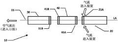
图1是根据本发明的一些实施例的电子烟的示意图(分解图)。1 is a schematic diagram (exploded view) of an electronic cigarette according to some embodiments of the present invention.
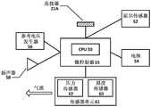
图2是根据本发明的一些实施例的图1的电子烟的本体的主要功能部件的示意图。2 is a schematic diagram of the main functional components of the body of the electronic cigarette of FIG. 1 according to some embodiments of the present invention.
图3A和图3B是根据现有设计的电子烟的管壳部分的示意图;特别地,图3A和图3B是两个在彼此正交的第一平面和第二平面中获得的截面,其均包括电子烟的纵向轴线LA。Figures 3A and 3B are schematic views of the casing part of an electronic cigarette according to a prior art design; in particular, Figures 3A and 3B are two cross-sections obtained in a first plane and a second plane orthogonal to each other, both of which are The longitudinal axis LA of the e-cigarette is included.
图4是根据现有设计的图3的电子烟的管壳部分的示意图,并且示出了在垂直于纵向轴线LA的平面中通过管壳部分的截面,在沿着管壳部分的长度的大约一半处获得该截面。FIG. 4 is a schematic view of the casing portion of the electronic cigarette of FIG. 3 according to the prior art design, and shows a cross-section through the casing portion in a plane perpendicular to the longitudinal axis LA, at approximately the length of the casing portion. This section is obtained halfway through.
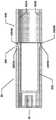
图5A和图5B举例说明了根据本发明的一些实施例的电子烟的管壳的一个实现方式,其中,图5A是通过管壳的水平截面(包括纵向轴线),而图5B是内容器本身的视图(即,如从外壳体内部移除)。Figures 5A and 5B illustrate one implementation of an electronic cigarette casing according to some embodiments of the present invention, wherein Figure 5A is a horizontal cross-section (including the longitudinal axis) through the casing and Figure 5B is the inner container itself view (i.e., as removed from inside the outer casing).
图6A和图6B举例说明了根据本发明的一些实施例的电子烟的管壳的一个实现方式,其中,图6A是通过管壳的水平截面(包括纵向轴线),而图6B是内容器本身的视图(即,如从外壳体内部移除)。Figures 6A and 6B illustrate one implementation of an electronic cigarette casing according to some embodiments of the present invention, wherein Figure 6A is a horizontal cross-section (including the longitudinal axis) through the casing and Figure 6B is the inner container itself view (i.e., as removed from inside the outer casing).
图7A和图7B举例说明了根据本发明的一些实施例的电子烟的管壳的一个实现方式,其中,图7A是通过管壳的水平截面(包括纵向轴线),而图7B是内容器本身的口端部分的视图(即,如从外壳体内部移除)。Figures 7A and 7B illustrate one implementation of an electronic cigarette casing according to some embodiments of the present invention, wherein Figure 7A is a horizontal cross-section (including the longitudinal axis) through the casing and Figure 7B is the inner container itself A view of the port end portion (ie, as removed from inside the outer housing).
图8A和图8B举例说明了根据本发明的一些实施例的电子烟的管壳的一个实现方式,其中,图8A是通过管壳的水平截面(包括纵向轴线),而图8B是内容器本身的视图(即,如从外壳体内部移除)。Figures 8A and 8B illustrate one implementation of an electronic cigarette casing according to some embodiments of the present invention, wherein Figure 8A is a horizontal cross-section (including the longitudinal axis) through the casing and Figure 8B is the inner container itself view (i.e., as removed from inside the outer casing).
图9A、图9B和图9C举例说明了根据本发明的一些实施例的电子烟的管壳的一个实现方式,其中,图9A是通过管壳的水平截面(包括纵向轴线),图9B是从竖直面(包括纵向轴线)向下截的外壳体的视图(即,没有内容器),而图9C是内容器本身的视图(即,如从外壳体内部移除的)。Figures 9A, 9B and 9C illustrate one implementation of an electronic cigarette casing according to some embodiments of the present invention, wherein Figure 9A is a horizontal cross-section (including the longitudinal axis) through the casing, and Figure 9B is taken from The vertical plane (including the longitudinal axis) is a view of the outer casing down (ie, without the inner container), while Figure 9C is a view of the inner container itself (ie, as removed from the interior of the outer casing).
图10举例说明了根据本发明的一些实施例的电子烟的管壳的一个实现方式,示出了通过管壳的水平截面(包括纵向轴线)。Figure 10 illustrates one implementation of an electronic cigarette casing according to some embodiments of the present invention, showing a horizontal cross-section (including the longitudinal axis) through the casing.
具体实施方式Detailed ways
如上所述,本发明涉及一种蒸汽供应系统,例如电子烟。在以下说明书中使用术语“电子烟”;然而,此术语可与(电子)蒸汽供应系统互换地使用。As described above, the present invention relates to a vapor supply system, such as an electronic cigarette. The term "electronic cigarette" is used in the following description; however, this term can be used interchangeably with an (electronic) vapor supply system.
图1是根据本发明的一些实施例的电子烟10的(不按比例的)示意图(分解图)。电子烟包括本体(控制单元)20、管壳30和蒸发器40。管壳包括内腔室,内腔室包含储液器和吸嘴35。储液器中的液体通常包括适当溶剂中的尼古丁,并且可包括其他成分,例如以帮助形成气溶胶,和/或产生额外的味道。管壳储液器可包括泡沫基质,或者任何其他用于保持液体直到需要将液体输送至蒸发器时的结构。控制单元20包括可再充电电池或电池以对电子烟10提供电力,并且包括用于通常控制电子烟的电路板。蒸发器40包括用于使液体蒸发的加热器,并且进一步包括芯子(wick)或类似装置,芯子或类似装置将少量液体从管壳中的储液器运送至加热器上或加热器附近的加热位置。当加热器从电池接收电力时,如由电路板所控制的,加热器使液体从芯子蒸发,然后用户通过吸嘴吸入此蒸汽。Figure 1 is a schematic (not to scale) schematic (exploded view) of an
控制单元20和蒸发器40可彼此拆开,但是当装置10在使用时连接在一起,例如,由螺旋接头或卡口接头(在图1中用41A和21A示意性地指示)连接在一起。控制单元和蒸发器之间的连接在二者之间提供机械连接和电连接。当使控制单元从蒸发器分离时,控制单元上的用来连接到蒸发器的电连接21A也用作用于连接充电装置(未示出)的插槽。充电装置的另一端可插入USB插槽以对电子烟的控制单元中的电池再充电。在其他实现方式中,电子烟可设置有用于在电连接21A和USB插槽之间进行方向连接的缆线。The
控制单元设置有一个或多个用于进气的孔(未在图1中示出)。这些孔通过控制单元连接到气道,连接到通过连接器21A提供的气道。然后,这通过蒸发器40连接到气路,并通过管壳30连接到吸嘴35。管壳30和蒸发器40在使用时由连接器41B和31B(再次在图1中示意性地示出)附接。如以上说明的,管壳包括容纳储液器的腔室,及吸嘴。当用户通过吸嘴35吸入时,将空气通过一个或多个进气孔吸入控制单元20。压力传感器检测到此气流(或者产生的压力变化),接着这激活加热器以使液体从管壳蒸发。气流从控制单元通过蒸发器,气流在蒸发器处与蒸汽结合,然后气流和(尼古丁)蒸汽的此组合物通过管壳并离开吸嘴35以由用户吸入。管壳30可从蒸发器40分离,并且当耗尽液体的供应时进行处理(然后用另一管壳替换)。注意,用户没有设备来再注满管壳。The control unit is provided with one or more holes for air intake (not shown in FIG. 1 ). These holes are connected to the airway through the control unit, to the airway provided by the
电子烟10具有纵向轴线或柱轴,纵向轴线或柱轴沿着电子烟的中心线从管壳30的一端处的吸嘴35延伸至控制单元20的相对端(通常叫做末端)。此纵向轴线在图1中用标记为LA的虚线表示。The
将理解,通过实例来提供图1所示的电子烟10,可采用多种其他实现方式。例如,在一些实施例中,可将蒸发器40集成在管壳中作为一个单元(有时叫做喷雾器),并且充电设备可连接到额外的或另选的电源,例如汽车点烟器。It will be appreciated that the
图2是根据本发明的一些实施例的图1的电子烟10的控制单元20的主要功能部件的示意图。这些部件可安装在位于控制单元20内的电路板上,虽然取决于特殊构造,但是在一些实施例中,一个或多个部件反而可容纳在控制单元中以与电路板联合操作,但是该一个或多个部件不会物理地安装在电路板本身上。FIG. 2 is a schematic diagram of the main functional components of the
控制单元20包括传感器单元61,其位于通过控制单元20从进气口到出气口(到蒸发器)的气路中或该气路附近。传感器单元包括压力传感器62和温度传感器63(也位于此气路中或气路附近)。控制单元进一步包括霍尔效应传感器52、参考电压发生器56、小扬声器58,以及用于连接到蒸发器40或连接到USB充电装置的电插槽或连接器21A。The
微控制器55包括CPU 50。CPU 50和其他电子部件(例如压力传感器62)的操作通常至少部分地由在CPU(或其他部件)上运行的软件程序控制。这种软件程序可储存在非易失性存储器中,例如ROM,其可集成在微控制器55本身中,或者作为单独的部件提供。CPU可访问ROM以当需要时加载并执行各个软件程序。微控制器55还包含合适的通信接口(和控制软件),其用于与控制单元10中的其他装置适当地通信,例如压力传感器62。The microcontroller 55 includes the
CPU控制扬声器58以产生音频输出,从而反映电子烟内的条件或状态,例如低电量警告。可通过使用不同音高和/或音长的声调或哔哔声,和/或通过提供多个这种哔哔声或声调,来提供用于发出不同状态或条件的信号不同的信号。The CPU controls the
如上所述,电子烟10提供这样的气路,其从进气口通过电子烟,经过压力传感器62和(蒸发器中的)加热器,到达吸嘴35。因此,当用户在电子烟的吸嘴上吸气时,CPU 50基于来自压力传感器的信息而检测到这种吸气。响应于这种检测,CPU从电池或电池54向加热器供应电力,从而加热器加热来自芯子的液体并使其蒸发以由用户吸入。As mentioned above, the
图3A和图3B以及图4是根据现有设计的电子烟10的管壳部分30的示意图。图4示出了在与纵向轴线LA垂直的平面中通过管壳部分的截面,在沿着管壳部分的长度的大约一半处获得该截面。图3A和图3B是在第一平面和第二平面中获得的两个截面,均包括纵向轴线LA。这些第一平面和第二平面彼此正交。为了方便起见,我们将把图3A所示的第一平面叫做水平面,并且把图3B所示的第二平面叫做竖直面。然而,将理解,虽然在正常使用中,电子烟10的纵向轴线LA大约是水平的,但是用户通常可以任何旋转角(方位角)将电子烟保持在此纵向轴线周围。因此,为了便于说明而采用术语竖直和水平,而不是特别暗示设定的装置使用方向。3A and 3B and FIG. 4 are schematic diagrams of the
如图3A、图3B和图4所示,管壳包含两个主要部分:外壳体200和内容器350。外壳体200在与纵向轴线LA垂直的平面中具有通常圆形的截面,如可在图4中看到的,从而形成通常柱形的管。外壳体分别具有相对的侧壁301A、301B,以及相对的顶壁301C和底壁301D。(将理解,这些壁301A-301D通常只是形成外壳体200的管的不同的、沿圆周隔开的部分)。As shown in FIGS. 3A , 3B and 4 , the package contains two main parts: an
对应于吸嘴35的位置,外壳体管的一端部分地由端壁39封闭,端壁39与纵向轴线LA垂直。在此端壁的中心形成孔,特别是形成内管37,内管37由内壁36限定。此内壁36同样形成通常为柱形的管,与由壁301A-301D形成的外壳体200的主外管平行。然而,此内管仅(沿着纵向轴线LA)从端壁39的径向最内侧部分向内延伸相对短的距离(与外管的长度相比)。Corresponding to the position of the
内容器350在与纵向轴线LA垂直的平面中也具有通常为圆形的截面,从而形成通常为柱形的管。特别地,内容器由此限定中心腔360,中心腔360容纳待蒸发液体的储液器,该液体通常是(溶液中的)尼古丁。内容器的在与吸嘴相对的一端处的开口352处(如图3A所示)可用薄壁封闭,例如使用金属箔,以产生密封腔室。可将液体保持在泡沫基质中的密封腔室内。外壳体200的内表面可在与口端35相对的一端处包括螺纹,以连接从而使管壳30附接到蒸发器部分40(见图1)。该附接可导致蒸发器部分上的芯子穿透管壳(例如通过刺穿储液器上的密封),从而将液体从储液器抽到蒸发器上。(请注意,为了清楚起见,从图3A和图3B省略了离吸嘴35最远的外壳体200和容器350的端部的细节,包括薄壁或其他密封,以及芯子的构造等)。The
内容器350的水平侧壁与外壳体的对应侧壁301A、301B邻接。特别地,在内容器350的水平侧壁和外壳体的对应侧壁301A、301B之间具有干涉配合,用来将内容器350保持在外壳体200内。此干涉配合的一部分在图3A中用参考数字354来表示,并且形成于外壳体200的侧壁301A和内容器的对应侧壁之间。注意,实际上在外壳体200上具有小锥度(未在图3中示出),以使得能够模制并支持此干涉配合-即,外壳体向内稍微逐渐变细以在口端处较窄。The horizontal side walls of the
内容器350的通常为柱形的管在吸嘴端处由壁370封闭。另外,外壳体200的侧壁301A和内容器的对应侧壁之间的干涉配合通常防止了空气沿着电子烟10流动。因此,虽然内容器350在垂直于纵向轴线LA的平面中具有通常为圆形的截面,但是使此圆形的最顶部变平以允许气流通过电子烟10。The generally cylindrical tube of the
特别地,内容器350的顶壁356由弦部(chord)形成(在图4的横截面中),而不是由弧形成。因此,这在外壳体200的顶壁301C和内容器350的顶壁356之间限定气道355。此气道355也在图3B中示出,连同表示从蒸发器部分40通过吸嘴35流出的气流的箭头一起示出。In particular, the
内容器350的位于吸嘴35附近的端壁370具有凸起358。此凸起在与电子烟10的纵向轴线LA平行的方向上延伸,以与外壳体200的端壁39邻接。该凸起在与电子烟10的纵向轴线LA垂直的平面中具有弧形的截面,并且位于内容器350的底部,即,与顶壁356相对。在此位置中,凸起358不阻止气流从气路355通过吸嘴35流出。The
另外,凸起358(在与纵向轴线LA平行的方向上)的长度比限定吸嘴管37的内壁36的长度大。因此,凸起358用来防止端壁370与吸嘴管37的内端邻接(从而封闭该内端)。因此,此构造再次帮助确保流过气道355的空气然后到达吸嘴管37,以通过吸嘴35离开。In addition, the length of the protrusion 358 (in a direction parallel to the longitudinal axis LA) is greater than the length of the
虽然如图3A、图3B和图4所示,根据现有设计的管壳30是起作用的,但是此设计对内容器350相对于外壳体200的相对尺寸设置严格的公差,以确保可成功地实现干涉配合354。因此,如果外壳体200相对于内容器350而言过大,那么内容器可能变得从其在管壳中的正确位置取出。相反,如果外壳体200相对于内容器350而言过小,那么可能无法将内容器插入外壳体200。内容器350相对于外壳体200的相对尺寸的严格公差会增加制造成本和/或导致产品可靠性问题。Although as shown in Figures 3A, 3B and 4, the
为了解决以上顾虑,已经开发了管壳30,在该管壳中,内容器350和外壳体200通过弹性闩锁机构而锁紧在一起。将理解的是,内容器350和/或外壳体200中的至少一个通常由塑料制成,其通常提供足够的柔性或弹性以支撑这种闩锁机构。To address the above concerns, a
图5A至图10举例说明了闩锁机构的多种不同的实现方式。这些实现方式可认为是相对于图3和图4描述的管壳30的改进。因此,在图5A至图10的讨论中,将不再描述这些实现方式的与已经相对于图3和图4描述的管壳30大致不变的方面,以避免重复。而且,将理解的是,图5A至图10的多种实现方式的目的不是排他的-而是技术人员将认识到多种可能的其他实现方式。另外,图5A至图10的多种实现方式的目的并不是互斥的,因为可适当地组合不同实现方式的一个或多个特征,以产生新的实现方式。Figures 5A-10 illustrate various different implementations of the latch mechanism. These implementations can be considered as improvements to the
图5A和图5B举例说明了管壳30的一个实现方式,其再次包括外壳体200和内容器350。特别地,图5A是通过管壳30的水平截面(包括纵向轴线LA),而图5B是内容器350本身的视图(即,如从外壳体200内部移除的)。FIGS. 5A and 5B illustrate one implementation of the
图5A和图5B的实现方式与图3A、图3B和图4的管壳的不同之处在于包含闩锁机构500。通过提供形成于内容器350中的凹槽510和对应的形成于外壳体200的内部上的伸出部505,来形成此闩锁机构。如可在图5B中看到的,凹槽510(相对于纵向轴线)围绕内容器的周缘延伸,而其不延伸越过顶壁356。凹槽具有稍微类似于数字“7”的形状,并且由两条边形成。第一条边位于离吸嘴35最远的地方并且相对于纵向轴线LA且相对于内容器350的圆柱形外表面具有相对较小的角度(shallow angle)或梯度。第二条边位于更靠近吸嘴35的地方并且相对于纵向轴线LA具有更陡的(可能是垂直的)角度或梯度。The implementation of FIGS. 5A and 5B differs from the casing of FIGS. 3A , 3B and 4 in that a
形成于外壳体200的内部上的伸出部505具有与凹槽510互补的形状。特别地,伸出部505围绕外壳体200的内壁的周缘延伸。然而,伸出部不延伸越过外壳体200的顶壁301C,以不阻塞气道355。伸出部505也具有稍微类似于数字“7”的形状(以与凹槽510匹配),并且由两条边形成。第一条边位于离吸嘴35最远的地方并且相对于纵向轴线LA且相对于外壳体200的柱形内表面具有相对较小的角度或梯度。第二条边位于更靠近吸嘴35的地方并且相对于纵向轴线LA具有更陡的(可能是垂直的)角度或梯度。The
将理解,一旦已按照图5A所示的实现方式将内容器350插入外壳体200,伸出部505的较陡的第二条边便与凹槽510的较陡的第二条边邻接。此邻接防止内容器350和外壳体200之间沿着纵向轴线的运动,特别是在将趋向于使内容器朝向离吸嘴35最远的外壳体200的一端移动的方向上。It will be appreciated that once the
图6A和图6B举例说明了管壳30的另一实现方式,该管壳还包括外壳体200和内容器350。特别地,图6A是通过管壳30的水平截面(包括纵向轴线LA),而图6B是内容器350本身的视图(即,如从外壳体200内部移除的)。FIGS. 6A and 6B illustrate another implementation of a
图6A和图6B的实现方式与图5A和图5B的实现方式类似。差别在于,在图5A和图5B的实现方式中,内容器350的壁的内面沿着管壳的纵向长度是平的。因此,内容器350的壁的形成凹槽510的部分比此壁的其余部分更薄,从而可能比其余部分更脆弱。然而,在图6A和图6B的实现方式中,内容器的壁605实际上具有大约恒定的厚度。这意味着,由内容器的壁605的对应凹口610将凹槽510的凹口反映在内容器的内部体积中。The implementations of FIGS. 6A and 6B are similar to the implementations of FIGS. 5A and 5B . The difference is that, in the implementation of Figures 5A and 5B, the inner face of the wall of the
将理解,图6A和图6B的实现方式中的闩锁机构500的操作与图5A和图5B的实现方式中的闩锁机构500的操作基本上类似。然而,图6A和图6B的实现方式避免对内容器350的壁605具有减小的厚度,这对于一些情况来说可能是重要的。It will be appreciated that the operation of the
图7A和图7B举例说明了管壳30的另一实现方式,该管壳还包括外壳体200和内容器350。特别地,图7A是通过管壳30的水平截面(包括纵向轴线LA),而图7B是内容器350本身(特别是口端35附近的部分)的视图(即,如从外壳体200内部移除的)。FIGS. 7A and 7B illustrate another implementation of a
在图7A和图7B的实现方式中,除了增加伸出部705以外,外壳体200通常与图3A、图3B和图4的实现方式相同。此伸出部位于外壳体200的吸嘴端附近,特别是位于内容器的端壁370和外壳体的端壁39之间。伸出部705直接径向地向内并且围绕外壳体200的内周缘而形成,即,伸出部相对于纵向轴线LA横跨从0度到360度的方位角。In the implementation of FIGS. 7A and 7B , the
伸出部705再次具有稍微类似于数字“7”的形状,并且由两条边形成。第一条边(斜坡部分)位于离吸嘴端35最远的地方并且相对于纵向轴线LA且也相对于外壳体200的柱形内表面具有相对较小的角度或梯度。第二条边(锁住部分)位于更靠近吸嘴35的地方并且相对于纵向轴线LA具有更陡的(可能是垂直的)角度或梯度。The
在图7A和图7B的实现方式中,除了增加第二凸起750以外,内容器350通常与图3A、图3B和图4的实现方式相同。此第二凸起750与第一凸起相同,因为该第二凸起从壁370朝向吸嘴端35延伸。然而,第二凸起比第一凸起稍短,使得第二凸起无法达到外壳体200的端壁39。另外,第二凸起750从内容器的顶壁356延伸,从而与第一凸起358(关于纵向轴线LA)直径相对,第一凸起358从内容器350的底部附近延伸。In the implementation of FIGS. 7A and 7B , the
第二凸起750的形状也与第一凸起358不同。因此,第二凸起750包括第一部分,该第一部分是平的且附接至端壁370。此平的部分实际上可认为是顶壁356的延伸部分。该平的部分也以悬臂的方式支撑凸起部分755。此凸起部分755与外壳体200的伸出部705相互作用,以形成闩锁机构500。然而注意,将外壳体的伸出部705的尺寸构造为不阻碍第一凸起358,第一凸起358可径向地向内通过伸出部705。The shape of the
凸起部分755也具有稍微类似于数字“7”的形状并且由两条边形成。第一条边位于离端壁370最远的地方并且相对于纵向轴线LA且也相对于内容器350的顶壁356具有相对较小的角度或梯度。第二条边位于更靠近吸嘴35的地方并且相对于纵向轴线LA具有更陡的(可能是垂直的)角度或梯度。The raised
可以看到,在操作中,当将内容器插入外壳体200时,第二凸起750的凸起部分755与外容器的向内的伸出部705接触。这导致第二凸起750在径向向内的(向下的)方向上稍微弯曲,从而允许凸起部分755滑过向内的伸出部705(和对着伸出部705滑动)。It can be seen that, in operation, when the inner container is inserted into the
最后,当完全插入内容器时,如图7A所示,伸出部705的拐角(即,较小的边接触陡边的地方)经过凸起部分755的拐角(还是是较小的边接触陡边的地方)。这允许第二凸起750弹性地向上弯曲回到图7A所示的位置。在此构造中,伸出部705的面向口端35的方向的陡边,与第二凸起750的凸起部分755的面向相反方向(远离口端)的陡边邻接。这两条边彼此邻接以对闩锁机构500提供锁紧作用,从而防止将内容器350从外壳体200收回。Finally, when the inner container is fully inserted, as shown in FIG. 7A , the corner of the extension 705 (ie, where the smaller side contacts the steep side) passes the corner of the raised portion 755 (which is also where the smaller side contacts the steep side). edge). This allows the
注意,在圆周(方位)程度上,即,相对于纵向轴线LA对向的旋转角,对于第二凸起750而言比对于第一凸起358而言更小。另外,相对于纵向轴线LA对向的旋转角,对于第二凸起750而言比对于内容器的顶壁356而言更小。这确保沿着气道355(见图3B)流动的空气能够在第二凸起周围流动(即,在第二凸起的任一侧上流动)以前进到吸嘴孔37,然后从电子烟10离开。Note that the extent of the circumference (azimuth), ie the angle of rotation subtended with respect to the longitudinal axis LA, is smaller for the
图7A和图7B所示的实现方式的一个特别的优点是,为了将内容器350插入外壳体200,这两个部件的两条纵向轴线必须相互对准(即重合)。然而,不需要使内容器350相对于外壳体200围绕纵向轴线LA旋转地对准,因为外壳体的向内的伸出部705横跨360度的旋转角。因此,第二凸起750将与向内的伸出部接合,不管在外壳体200和内容器350之间插入的相对旋转角如何。因此,这避免需要在将内容器350插入外壳体200之前在这两个部件之间执行旋转对准,这可帮助减小制造复杂性(从而降低成本)。A particular advantage of the implementation shown in Figures 7A and 7B is that in order to insert the
图7A和图7B的实施例还避免具有在内容器350中形成的凹槽部分,从而避免任何可能的脆弱。另外,与图6A的实施例不同,内容器的内部形状是不变的。这可帮助保持内容器350的最大体积,并且避免任何关于填充过程的可能的困难。The embodiment of Figures 7A and 7B also avoids having grooved portions formed in the
图8A和图8B举例说明了管壳30的另一实现方式,该管壳也包括外壳体200和内容器350。特别地,图8A是通过管壳30的垂直截面(包括纵向轴线LA),而图8B是内容器350本身的视图(即,如从外壳体200内部移除的)。FIGS. 8A and 8B illustrate another implementation of a
在图8A和图8B的实现方式中,除了增加伸出部805以外,外壳体200通常与图3A、图3B和图4的实现方式相同。除了该伸出部的位置以外,此伸出部通常与图7A和图7B的实现方式中的伸出部705类似。因此,伸出部805不在口端35附近,而是位于靠近离口端35最远的内容器350的端部附近(当内容器已经完全插入外壳体200时)。In the implementation of FIGS. 8A and 8B , the
伸出部805是直接径向向内的并且还具有稍微类似于数字“7”的形状并且由两条边形成。第一条边(斜坡部分)位于离吸嘴端35最远的地方并且相对于纵向轴线LA且也相对于外壳体200的柱形内表面具有相对较小的角度或梯度。第二条边(锁住部分)位于更靠近吸嘴35的地方并且相对于纵向轴线LA具有更陡的(可能是垂直的)角度或梯度。The
在图8A和图8B的实现方式中,除了增加伸出部850以外,内容器350通常与图3A、图3B和图4的实现方式相同,伸出部850形成于内容器的顶壁356上并且径向地指向外部。伸出部850也具有稍微类似于数字“7”的形状并且由两条边形成。第一条边位于离端壁370最近的地方并且相对于纵向轴线LA且也相对于内容器350的顶壁356具有相对较小的角度或梯度(斜坡部分)。第二条边位于离端壁370更远的地方并且相对于纵向轴线LA具有更陡的(可能是垂直的)角度或梯度。In the implementation of FIGS. 8A and 8B , the
在操作中,当将内容器插入外壳体200时,内容器350上的伸出部850的斜坡部分与外容器的向内的伸出部805的对应斜坡部分接触。最后,当完全插入内容器时,如图8A所示,伸出部805的面向口端35的方向的陡边,与内容器伸出部850的面向相反方向(远离口端)的陡边邻接。这两条边彼此邻接,以对闩锁机构500提供锁紧作用,从而防止将内容器350从外壳体200收回。In operation, when the inner container is inserted into the
注意,内容器350的顶壁356上的伸出部850的宽度比顶壁356的宽度小。这确保沿着气道355(见图3B)流动的空气能够在伸出部850周围流动,即,在其任一侧上流动,以前进到吸嘴孔37,然后从电子烟10离开。Note that the width of the
图9A、图9B和图9C举例说明了管壳30的另一实现方式,该管壳也包括外壳体200和内容器350。特别地,图9A是通过管壳30的水平截面(包括纵向轴线LA),图9B是已经使竖直面分开的外壳体200(没有内容器350)的视图,并且图9C是内容器350本身的视图(即,如从外壳体200内部移除的)。FIGS. 9A , 9B and 9C illustrate another implementation of a
在图9A至图9C的实现方式中,除了在外壳体的内壁中增加环形槽905以外,外壳体200通常与图3A、图3B和图4的实现方式相同。更特别地,围绕外壳体200的内周缘形成凹槽905,即,凹糟相对于纵向轴线LA横跨从0度到360度的方位角。凹槽905再次具有稍微类似于数字“7”的形状并且由两条边形成。第一条边(斜坡部分)位于离吸嘴端35最远的地方并且相对于纵向轴线LA且也相对于外壳体200的柱形内表面具有相对较小的角度或梯度。第二条边(锁住部分)位于更靠近吸嘴35的地方并且相对于纵向轴线LA具有更陡的(可能是垂直的)角度或梯度。In the implementation of FIGS. 9A-9C , the
在图9A至图9C的实现方式中,除了增加伸出部950A、950B以外,内容器350通常与图3A、图3B和图4的实现方式相同,伸出部950A、950B形成于内容器的每个侧壁上并且径向地指向外部。伸出部950A、950B再次具有稍微类似于数字“7”的形状,并且各自由两条边形成。第一条边位于离端壁370最近的地方并且相对于纵向轴线LA具有相对较小的角度或梯度(斜坡部分)。第二条边位于离端壁370更远的地方并且相对于纵向轴线LA具有更陡的(可能是垂直的)角度或梯度。In the implementation of FIGS. 9A-9C, the
在操作中,当将内容器插入外壳体200时,内容器350上的伸出部950A、950B的斜坡部分与外容器200的对应内壁接触,该对应内壁由此向外稍微弯曲。最后,当完全插入内容器时,如图9A所示,伸出部950A、950B的面向远离口端35的方向的陡边,与凹槽905的面向相反方向(朝向口端)的陡边邻接。这两条边在凹槽位置950A、950B处彼此邻接,以对闩锁机构500提供锁紧作用,从而防止将内容器350从外壳体200收回。In operation, when the inner container is inserted into the
图9A至图9C所示的实现方式的一个特别的优点再次是,不需要使内容器350相对于外壳体200围绕纵向轴线LA旋转地对准,因为外壳体的向内的凹槽905横跨360度的旋转角。因此,外壳体200的凹槽905将与内容器的伸出部950A、950B接合,不管在外壳体200和内容器350之间插入的相对旋转角如何。因此,这避免需要在将内容器350插入外壳体200之前在这两个部件之间执行旋转对准,这可帮助减小制造复杂性(从而降低成本)。A particular advantage of the implementation shown in FIGS. 9A-9C is, again, that there is no need to rotationally align the
图10举例说明了管壳30的另一实现方式,该管壳再次包括外壳体200和内容器350。特别地,图10是通过管壳30的水平截面(包括纵向轴线LA)。图10的实现方式通常与图9A至图9C的实现方式相同,因为具有形成于外壳体200的圆柱形内壁上的环形槽1005,并且这与内容器350的相应侧上的两个对应伸出部1050A、1050B形成闩锁机构500。FIG. 10 illustrates another implementation of the
关于环形槽1005沿着纵向轴线LA的定位,及由此伸出部1050A、1050B的对应定位,图10的实现方式与图9A至图9C的实现方式不同。特别地,伸出部1050A、1050B现在位于内容器的离口端35最远的一端(类似于尾翼)。此定位可提供某些优点。例如,当在接合闩锁机构500之前将内容器350插入外壳体200时,在离端壁39和口端35更远且离外壳体200的(相对的)开口端更近的地方,出现外壳体的弯曲以适应伸出部1050A、1050B。将理解,此开口端将自然地具有稍微增加的柔性。With regard to the positioning of the annular groove 1005 along the longitudinal axis LA, and thus the corresponding positioning of the protrusions 1050A, 1050B, the implementation of Figure 10 differs from the implementation of Figures 9A to 9C. In particular, the
虽然本文已经公开了多种闩锁机构500,但是将理解,这些通过实例提供,并且许多额外的关于闩锁机构的形状、定位、操作等的可能性对于本领域普通技术人员来说将是显而易见的。而且,虽然本文描述的电子烟包括三个可分离的段,即,控制单元、管壳和蒸发器,但是将理解,其他电子烟可包括不同数量的段。While
为了解决各种问题并使技术前进,本发明通过例证示出了多种实施例,在这些实施例中可实践所要求的发明。本发明的优点和特征仅是这些实施例的代表性样本,并不是彻底的和/或排他的。其仅用来帮助理解并教导所要求的发明。将理解,本发明的优点、实施例、实例、功能、特征、结构和/或其他方面并不被认为是对如由权利要求书定义的本发明的限制,或是对与权利要求书等价的内容的限制,并且,在不背离权利要求书的范围的情况下,可利用其他实施例并可进行修改。多种实施例可适当地包括除了本文具体描述的那些以外的所公开的元件、部件、特征、零件、步骤、方式等的各种组合,由这些组合组成,或者本质上由这些组合组成。本发明可包括其他目前未要求但是可能在未来要求的发明。In order to solve various problems and to advance the technology, the present invention presents, by way of illustration, various embodiments in which the claimed invention may be practiced. The advantages and features of the present invention are only a representative sample of these embodiments, and are not exhaustive and/or exclusive. It is used only to aid in understanding and teaching the claimed invention. It is to be understood that advantages, embodiments, examples, functions, features, structures and/or other aspects of the invention are not to be considered limitations of the invention as defined by the claims, or equivalents to the claims content, and other embodiments may be utilized and modifications may be made without departing from the scope of the claims. Various embodiments may suitably include, consist of, or consist essentially of various combinations of the disclosed elements, components, features, parts, steps, means, etc. other than those specifically described herein. The present invention may include other inventions that are not presently claimed, but may be claimed in the future.
Claims (18)
Translated fromChineseApplications Claiming Priority (4)
| Application Number | Priority Date | Filing Date | Title |
|---|---|---|---|
| GBGB1501060.6AGB201501060D0 (en) | 2015-01-22 | 2015-01-22 | Vapour provision system and cartridge therefor |
| GB1501060.6 | 2015-01-22 | ||
| PCT/GB2016/050126WO2016116754A1 (en) | 2015-01-22 | 2016-01-21 | Vapour provision system and cartridge therefor |
| CN201680006679.2ACN107205492A (en) | 2015-01-22 | 2016-01-21 | Steam supply system and its casing |
Related Parent Applications (1)
| Application Number | Title | Priority Date | Filing Date |
|---|---|---|---|
| CN201680006679.2ADivisionCN107205492A (en) | 2015-01-22 | 2016-01-21 | Steam supply system and its casing |
Publications (1)
| Publication Number | Publication Date |
|---|---|
| CN115104774Atrue CN115104774A (en) | 2022-09-27 |
Family
ID=52673777
Family Applications (2)
| Application Number | Title | Priority Date | Filing Date |
|---|---|---|---|
| CN201680006679.2APendingCN107205492A (en) | 2015-01-22 | 2016-01-21 | Steam supply system and its casing |
| CN202210894198.7APendingCN115104774A (en) | 2015-01-22 | 2016-01-21 | Steam supply system and pipe shell thereof |
Family Applications Before (1)
| Application Number | Title | Priority Date | Filing Date |
|---|---|---|---|
| CN201680006679.2APendingCN107205492A (en) | 2015-01-22 | 2016-01-21 | Steam supply system and its casing |
Country Status (17)
| Country | Link |
|---|---|
| US (2) | US10517327B2 (en) |
| EP (2) | EP3524073A3 (en) |
| JP (3) | JP6553195B2 (en) |
| KR (3) | KR102034790B1 (en) |
| CN (2) | CN107205492A (en) |
| BR (1) | BR112017015759B1 (en) |
| CA (1) | CA2973654C (en) |
| DE (3) | DE202016008830U1 (en) |
| ES (1) | ES2733803T3 (en) |
| GB (1) | GB201501060D0 (en) |
| HK (1) | HK1246607B (en) |
| MY (1) | MY188741A (en) |
| PH (1) | PH12017501324A1 (en) |
| PL (1) | PL3247233T3 (en) |
| RU (1) | RU2665451C1 (en) |
| UA (1) | UA123539C2 (en) |
| WO (1) | WO2016116754A1 (en) |
Families Citing this family (45)
| Publication number | Priority date | Publication date | Assignee | Title |
|---|---|---|---|---|
| US20160345631A1 (en) | 2005-07-19 | 2016-12-01 | James Monsees | Portable devices for generating an inhalable vapor |
| US10279934B2 (en) | 2013-03-15 | 2019-05-07 | Juul Labs, Inc. | Fillable vaporizer cartridge and method of filling |
| DE202014011260U1 (en) | 2013-12-23 | 2018-11-13 | Juul Labs Uk Holdco Limited | Systems for an evaporation device |
| USD842536S1 (en) | 2016-07-28 | 2019-03-05 | Juul Labs, Inc. | Vaporizer cartridge |
| USD825102S1 (en) | 2016-07-28 | 2018-08-07 | Juul Labs, Inc. | Vaporizer device with cartridge |
| US20160366947A1 (en) | 2013-12-23 | 2016-12-22 | James Monsees | Vaporizer apparatus |
| US10159282B2 (en) | 2013-12-23 | 2018-12-25 | Juul Labs, Inc. | Cartridge for use with a vaporizer device |
| US10058129B2 (en) | 2013-12-23 | 2018-08-28 | Juul Labs, Inc. | Vaporization device systems and methods |
| US10076139B2 (en) | 2013-12-23 | 2018-09-18 | Juul Labs, Inc. | Vaporizer apparatus |
| MX394125B (en) | 2014-12-05 | 2025-03-24 | Juul Labs Inc | CALIBRATED DOSE CONTROL |
| GB201501060D0 (en)* | 2015-01-22 | 2015-03-11 | Nicoventures Holdings Ltd | Vapour provision system and cartridge therefor |
| EP3135139B1 (en)* | 2015-08-28 | 2024-04-10 | Fontem Ventures B.V. | Electronic smoking device with integrated mouthpiece and capsule assembly |
| CO2018009342A2 (en) | 2016-02-11 | 2018-09-20 | Juul Labs Inc | Secure fixing cartridges for vaporizing devices |
| EP3413960B1 (en) | 2016-02-11 | 2021-03-31 | Juul Labs, Inc. | Fillable vaporizer cartridge and method of filling |
| US10455863B2 (en)* | 2016-03-03 | 2019-10-29 | Altria Client Services Llc | Cartridge for electronic vaping device |
| US10433580B2 (en) | 2016-03-03 | 2019-10-08 | Altria Client Services Llc | Methods to add menthol, botanic materials, and/or non-botanic materials to a cartridge, and/or an electronic vaping device including the cartridge |
| US10368580B2 (en) | 2016-03-08 | 2019-08-06 | Altria Client Services Llc | Combined cartridge for electronic vaping device |
| US10405582B2 (en) | 2016-03-10 | 2019-09-10 | Pax Labs, Inc. | Vaporization device with lip sensing |
| US10357060B2 (en) | 2016-03-11 | 2019-07-23 | Altria Client Services Llc | E-vaping device cartridge holder |
| US10368581B2 (en) | 2016-03-11 | 2019-08-06 | Altria Client Services Llc | Multiple dispersion generator e-vaping device |
| WO2017185051A1 (en) | 2016-04-22 | 2017-10-26 | Pax Labs, Inc. | Aerosol devices having compartmentalized materials |
| USD849996S1 (en) | 2016-06-16 | 2019-05-28 | Pax Labs, Inc. | Vaporizer cartridge |
| USD851830S1 (en) | 2016-06-23 | 2019-06-18 | Pax Labs, Inc. | Combined vaporizer tamp and pick tool |
| USD836541S1 (en) | 2016-06-23 | 2018-12-25 | Pax Labs, Inc. | Charging device |
| US10383367B2 (en) | 2016-07-25 | 2019-08-20 | Fontem Holdings 1 B.V. | Electronic cigarette power supply portion |
| IT201600084349A1 (en)* | 2016-08-10 | 2018-02-10 | Smart Evolution Trading S P A | PALM TREATMENT SYSTEM FOR PERSONAL USE, IN PARTICULAR AN ELECTRONIC CIGARETTE SYSTEM |
| WO2018114441A1 (en) | 2016-12-19 | 2018-06-28 | Philip Morris Products S.A. | An aerosol-generating system comprising multiple aerosol-forming substrates and a piercing element |
| US11045615B2 (en) | 2016-12-19 | 2021-06-29 | Altria Client Services Llc | Vapor-generating systems |
| GB201709201D0 (en)* | 2017-06-09 | 2017-07-26 | Nicoventures Holdings Ltd | Electronic aerosol provision system |
| USD887632S1 (en) | 2017-09-14 | 2020-06-16 | Pax Labs, Inc. | Vaporizer cartridge |
| JP7285856B2 (en) | 2018-04-24 | 2023-06-02 | ジェイティー インターナショナル エス.エイ. | Electronic cigarette with optimized vaporization |
| US11918045B2 (en) | 2018-04-24 | 2024-03-05 | Jt International S.A. | Electronic cigarette with optimised vaporisation |
| WO2019243612A1 (en)* | 2018-06-21 | 2019-12-26 | Philip Morris Products S.A. | Resealable cartridge assembly for an aerosol-generating system |
| CN116898146A (en)* | 2018-06-27 | 2023-10-20 | 尤尔实验室有限公司 | Evaporator device |
| US10888125B2 (en) | 2018-06-27 | 2021-01-12 | Juul Labs, Inc. | Vaporizer device with subassemblies |
| CN119632302A (en) | 2018-07-31 | 2025-03-18 | 尤尔实验室有限公司 | Cartridge-based heat-without-burn vaporizer |
| JP7502015B2 (en) | 2018-11-08 | 2024-06-18 | ジュール・ラブズ・インコーポレイテッド | Vaporizer device with one or more heating elements |
| US11445759B2 (en) | 2018-11-20 | 2022-09-20 | Altria Client Services Llc | E-vaping device |
| US11311049B2 (en) | 2018-11-20 | 2022-04-26 | Altria Client Services Llc | Air intake assembly |
| GB201912477D0 (en) | 2019-08-30 | 2019-10-16 | Nicoventures Trading Ltd | Aerosol provision systems |
| US20230256441A1 (en)* | 2020-08-26 | 2023-08-17 | Sense Biodetection Limited | Devices |
| US11690400B2 (en) | 2020-08-28 | 2023-07-04 | E-Cone LLC | Self-igniting cap for a pipe |
| KR102490572B1 (en) | 2020-09-23 | 2023-01-19 | 주식회사 케이티앤지 | Aerosol generating apparatus |
| DE102023127959A1 (en)* | 2023-10-12 | 2025-04-17 | Hakan Koca | E-cigarette with noise module |
| CN117918593A (en)* | 2024-03-07 | 2024-04-26 | 深圳市吉迩科技有限公司 | Atomizer and assembly method thereof and aerosol generating device |
Citations (2)
| Publication number | Priority date | Publication date | Assignee | Title |
|---|---|---|---|---|
| CN101843368A (en)* | 2010-04-02 | 2010-09-29 | 陈志平 | Suction nozzle of electronic atomizer |
| WO2013110208A1 (en)* | 2012-01-24 | 2013-08-01 | Maas Bernard Karel | Electronic simulation cigarette and simulation cigarette mouthpiece therefor |
Family Cites Families (43)
| Publication number | Priority date | Publication date | Assignee | Title |
|---|---|---|---|---|
| US2968307A (en) | 1955-12-21 | 1961-01-17 | Filtox S A | Cigarette or cigar holder |
| US3515146A (en) | 1967-06-27 | 1970-06-02 | Raymond N Nealis | Aromatic filter |
| EP0235736B1 (en) | 1986-03-06 | 1991-05-15 | Carlo Lugli | Improved mouth-piece for filtering the smoke of cigarettes and the like |
| US5167242A (en) | 1990-06-08 | 1992-12-01 | Kabi Pharmacia Aktiebolaq | Nicotine-impermeable container and method of fabricating the same |
| US5470257A (en)* | 1994-09-12 | 1995-11-28 | John Mezzalingua Assoc. Inc. | Radial compression type coaxial cable end connector |
| ES2363333T3 (en) | 2001-11-14 | 2011-08-01 | Novartis Ag | AEROSOL SPRAYING DEVICE INCLUDING A CONNECTABLE BODY AND TERMINAL PIECE. |
| CN100381083C (en) | 2003-04-29 | 2008-04-16 | 韩力 | Non-combustible electronic spray cigarette |
| CN2719043Y (en) | 2004-04-14 | 2005-08-24 | 韩力 | Atomized electronic cigarette |
| DE202006001663U1 (en) | 2006-02-03 | 2006-04-27 | Kieslich, Dirk | Smoke-free cigarette with nicotine and flavor cushions but without harmful combustion substances and side effects |
| US8042550B2 (en) | 2006-11-02 | 2011-10-25 | Vladimir Nikolaevich Urtsev | Smoke-simulating pipe |
| ATE418276T1 (en) | 2007-01-19 | 2009-01-15 | Grischa Plast Ag | SMOKELESS CIGARETTE, CIGARILLO, CIGAR OR THE LIKE. |
| EP1972215A1 (en) | 2007-03-20 | 2008-09-24 | Wedegree GmbH | Smoke-free cigarette substitute |
| US20090014212A1 (en)* | 2007-07-13 | 2009-01-15 | Malak Stephen P | Micro encapsulation seal for coaxial cable connectors and method of use thereof |
| CA2709071C (en) | 2007-12-14 | 2016-11-15 | Labogroup S.A.S. | Delivering aerosolizable food products |
| US8991402B2 (en) | 2007-12-18 | 2015-03-31 | Pax Labs, Inc. | Aerosol devices and methods for inhaling a substance and uses thereof |
| CN202197836U (en) | 2008-06-27 | 2012-04-25 | 马斯·伯纳德 | alternative to cigarettes |
| JP5355309B2 (en) | 2008-09-24 | 2013-11-27 | キヤノン株式会社 | Chemical solution container and inhalation chemical solution discharge device |
| EP2370209A2 (en)* | 2008-12-03 | 2011-10-05 | Le Labogroup SAS | Delivering aerosolizable food products |
| CN201319860Y (en) | 2008-12-25 | 2009-10-07 | 中国科学院理化技术研究所 | Electronic cigarette adopting capacitor for power supply |
| DK2456329T3 (en) | 2009-07-22 | 2013-07-15 | Philip Morris Prod | Smoke-free cigarette replacement product |
| CA2789362C (en) | 2010-02-24 | 2014-05-27 | Japan Tobacco Inc. | Flavor inhalation pipe |
| US8689786B2 (en) | 2010-05-25 | 2014-04-08 | British American Tobacco (Investments) Limited | Aerosol generator |
| CA2807331C (en) | 2010-08-20 | 2015-05-19 | Japan Tobacco Inc. | Tobacco-flavor-releasing material and non-heating type tobacco flavor inhalator containing same |
| EA019736B1 (en)* | 2010-12-01 | 2014-05-30 | Евгений Иванович Евсюков | Inhaling device |
| CN201888252U (en)* | 2010-12-07 | 2011-07-06 | 罗青 | Electronic cigarette with filtering function |
| RU103281U1 (en)* | 2010-12-27 | 2011-04-10 | Общество с ограниченной ответственностью "ПромКапитал" | ELECTRONIC CIGARETTE |
| CN202005248U (en) | 2011-01-21 | 2011-10-12 | 万利龙 | Electronic atomization device capable substituting cigarette |
| DE102011010532A1 (en) | 2011-02-07 | 2012-08-09 | S.A.S.C. Ag | inhalator |
| CN202068930U (en) | 2011-03-18 | 2011-12-14 | 万利龙 | Filter cigarette holder and electronic cigarette device comprising same |
| WO2012155058A1 (en) | 2011-05-11 | 2012-11-15 | Breathable Foods, Inc. | Aerosol delivery apparatus |
| US20120312313A1 (en) | 2011-06-07 | 2012-12-13 | Vapor Corp. | Padded cartridge for an electronic smoking apparatus |
| KR102059699B1 (en) | 2011-07-13 | 2019-12-26 | 파맥시스 엘티디 | Improvements relating to delivery devices |
| AU2012342570B2 (en) | 2011-11-21 | 2016-11-24 | Philip Morris Products S.A. | Ejector for an aerosol-generating device |
| US8815174B2 (en)* | 2012-08-17 | 2014-08-26 | American Sterilizer Company | Steam sterilizer |
| US8910639B2 (en)* | 2012-09-05 | 2014-12-16 | R. J. Reynolds Tobacco Company | Single-use connector and cartridge for a smoking article and related method |
| GB2507102B (en)* | 2012-10-19 | 2015-12-30 | Nicoventures Holdings Ltd | Electronic inhalation device |
| US9423152B2 (en) | 2013-03-15 | 2016-08-23 | R. J. Reynolds Tobacco Company | Heating control arrangement for an electronic smoking article and associated system and method |
| CN103300480B (en) | 2013-06-06 | 2015-05-13 | 深圳市康尔科技有限公司 | Leak-proof atomizer |
| ITMO20130192A1 (en) | 2013-06-28 | 2014-12-29 | Damco S R L | KIT FOR ELECTRONIC CIGARETTES |
| CN103462224B (en) | 2013-08-31 | 2015-10-14 | 卓尔悦(常州)电子科技有限公司 | Electronic smoke atomizer |
| US20150305409A1 (en)* | 2013-11-12 | 2015-10-29 | VMR Products, LLC | Vaporizer |
| CN103720055A (en)* | 2013-12-13 | 2014-04-16 | 深圳市合元科技有限公司 | Electronic cigarette and atomizing device and power supply device and charging connector thereof |
| GB201501060D0 (en)* | 2015-01-22 | 2015-03-11 | Nicoventures Holdings Ltd | Vapour provision system and cartridge therefor |
- 2015
- 2015-01-22GBGBGB1501060.6Apatent/GB201501060D0/ennot_activeCeased
- 2016
- 2016-01-21DEDE202016008830.1Upatent/DE202016008830U1/enactiveActive
- 2016-01-21KRKR1020177020533Apatent/KR102034790B1/enactiveActive
- 2016-01-21EPEP19165920.0Apatent/EP3524073A3/enactivePending
- 2016-01-21DEDE202016008832.8Upatent/DE202016008832U1/enactiveActive
- 2016-01-21KRKR1020217031796Apatent/KR102581948B1/enactiveActive
- 2016-01-21EPEP16701857.1Apatent/EP3247233B1/enactiveActive
- 2016-01-21ESES16701857Tpatent/ES2733803T3/enactiveActive
- 2016-01-21JPJP2017538605Apatent/JP6553195B2/enactiveActive
- 2016-01-21DEDE202016008829.8Upatent/DE202016008829U1/enactiveActive
- 2016-01-21UAUAA201707716Apatent/UA123539C2/enunknown
- 2016-01-21CACA2973654Apatent/CA2973654C/enactiveActive
- 2016-01-21PLPL16701857Tpatent/PL3247233T3/enunknown
- 2016-01-21MYMYPI2017702616Apatent/MY188741A/enunknown
- 2016-01-21RURU2017125932Apatent/RU2665451C1/enactive
- 2016-01-21HKHK18106142.4Apatent/HK1246607B/enunknown
- 2016-01-21CNCN201680006679.2Apatent/CN107205492A/enactivePending
- 2016-01-21CNCN202210894198.7Apatent/CN115104774A/enactivePending
- 2016-01-21KRKR1020197030281Apatent/KR102311621B1/enactiveActive
- 2016-01-21BRBR112017015759-4Apatent/BR112017015759B1/enactiveIP Right Grant
- 2016-01-21USUS15/544,694patent/US10517327B2/enactiveActive
- 2016-01-21WOPCT/GB2016/050126patent/WO2016116754A1/ennot_activeCeased
- 2017
- 2017-07-21PHPH12017501324Apatent/PH12017501324A1/enunknown
- 2019
- 2019-07-03JPJP2019124230Apatent/JP6891226B2/enactiveActive
- 2019-11-26USUS16/696,784patent/US11006675B2/enactiveActive
- 2021
- 2021-05-26JPJP2021088088Apatent/JP7261263B2/enactiveActive
Patent Citations (2)
| Publication number | Priority date | Publication date | Assignee | Title |
|---|---|---|---|---|
| CN101843368A (en)* | 2010-04-02 | 2010-09-29 | 陈志平 | Suction nozzle of electronic atomizer |
| WO2013110208A1 (en)* | 2012-01-24 | 2013-08-01 | Maas Bernard Karel | Electronic simulation cigarette and simulation cigarette mouthpiece therefor |
Also Published As
Similar Documents
| Publication | Publication Date | Title |
|---|---|---|
| US11006675B2 (en) | Vapor provision system and cartridge therefor | |
| HK1246607A1 (en) | Vapour provision system and cartridge therefor | |
| CN106535682B (en) | Electronic steam supply system and body part for electronic steam supply system | |
| US11872341B2 (en) | Vapor provision cartridge and system | |
| JP6734458B2 (en) | Non-combustion aspirator | |
| TW201515586A (en) | Electronic smoking device and method of manufacturing same | |
| CN110381759B (en) | Cartridge assembly comprising a blocking element | |
| CN108472458A (en) | Cartridge assembly with sliding barrel | |
| WO2020084799A1 (en) | Power source unit for non-combustion-type inhaler, atomization unit, and non-combustion-type inhaler | |
| JP2020074762A (en) | Power supply unit of non-combustion type sucker, body unit and non-combustion type sucker | |
| RU2795871C2 (en) | Vapor preparation system and cartridge for it | |
| EP3871543B1 (en) | Atomization unit of non-combustion suction device, power unit of non-combustion suction device, and non-combustion suction device | |
| HK40009356A (en) | Vapour provision system and cartridge therefor | |
| EP3955998B1 (en) | Aerosol provision system | |
| CN112203535B (en) | Activatable and reclosable cartridge assembly for an aerosol generating system |
Legal Events
| Date | Code | Title | Description |
|---|---|---|---|
| PB01 | Publication | ||
| PB01 | Publication | ||
| SE01 | Entry into force of request for substantive examination | ||
| SE01 | Entry into force of request for substantive examination |