CN115103897A - Connector with a locking member - Google Patents
Connector with a locking memberDownload PDFInfo
- Publication number
- CN115103897A CN115103897ACN202080096868.XACN202080096868ACN115103897ACN 115103897 ACN115103897 ACN 115103897ACN 202080096868 ACN202080096868 ACN 202080096868ACN 115103897 ACN115103897 ACN 115103897A
- Authority
- CN
- China
- Prior art keywords
- connector
- hollow needle
- seal
- housing
- receiver
- Prior art date
- Legal status (The legal status is an assumption and is not a legal conclusion. Google has not performed a legal analysis and makes no representation as to the accuracy of the status listed.)
- Pending
Links
Images


Classifications
- C—CHEMISTRY; METALLURGY
- C12—BIOCHEMISTRY; BEER; SPIRITS; WINE; VINEGAR; MICROBIOLOGY; ENZYMOLOGY; MUTATION OR GENETIC ENGINEERING
- C12M—APPARATUS FOR ENZYMOLOGY OR MICROBIOLOGY; APPARATUS FOR CULTURING MICROORGANISMS FOR PRODUCING BIOMASS, FOR GROWING CELLS OR FOR OBTAINING FERMENTATION OR METABOLIC PRODUCTS, i.e. BIOREACTORS OR FERMENTERS
- C12M23/00—Constructional details, e.g. recesses, hinges
- C12M23/38—Caps; Covers; Plugs; Pouring means
- C—CHEMISTRY; METALLURGY
- C12—BIOCHEMISTRY; BEER; SPIRITS; WINE; VINEGAR; MICROBIOLOGY; ENZYMOLOGY; MUTATION OR GENETIC ENGINEERING
- C12M—APPARATUS FOR ENZYMOLOGY OR MICROBIOLOGY; APPARATUS FOR CULTURING MICROORGANISMS FOR PRODUCING BIOMASS, FOR GROWING CELLS OR FOR OBTAINING FERMENTATION OR METABOLIC PRODUCTS, i.e. BIOREACTORS OR FERMENTERS
- C12M33/00—Means for introduction, transport, positioning, extraction, harvesting, peeling or sampling of biological material in or from the apparatus
- C12M33/04—Means for introduction, transport, positioning, extraction, harvesting, peeling or sampling of biological material in or from the apparatus by injection or suction, e.g. using pipettes, syringes, needles
- A—HUMAN NECESSITIES
- A61—MEDICAL OR VETERINARY SCIENCE; HYGIENE
- A61J—CONTAINERS SPECIALLY ADAPTED FOR MEDICAL OR PHARMACEUTICAL PURPOSES; DEVICES OR METHODS SPECIALLY ADAPTED FOR BRINGING PHARMACEUTICAL PRODUCTS INTO PARTICULAR PHYSICAL OR ADMINISTERING FORMS; DEVICES FOR ADMINISTERING FOOD OR MEDICINES ORALLY; BABY COMFORTERS; DEVICES FOR RECEIVING SPITTLE
- A61J1/00—Containers specially adapted for medical or pharmaceutical purposes
- A61J1/14—Details; Accessories therefor
- A61J1/20—Arrangements for transferring or mixing fluids, e.g. from vial to syringe
- A—HUMAN NECESSITIES
- A61—MEDICAL OR VETERINARY SCIENCE; HYGIENE
- A61J—CONTAINERS SPECIALLY ADAPTED FOR MEDICAL OR PHARMACEUTICAL PURPOSES; DEVICES OR METHODS SPECIALLY ADAPTED FOR BRINGING PHARMACEUTICAL PRODUCTS INTO PARTICULAR PHYSICAL OR ADMINISTERING FORMS; DEVICES FOR ADMINISTERING FOOD OR MEDICINES ORALLY; BABY COMFORTERS; DEVICES FOR RECEIVING SPITTLE
- A61J1/00—Containers specially adapted for medical or pharmaceutical purposes
- A61J1/14—Details; Accessories therefor
- A61J1/20—Arrangements for transferring or mixing fluids, e.g. from vial to syringe
- A61J1/2003—Accessories used in combination with means for transfer or mixing of fluids, e.g. for activating fluid flow, separating fluids, filtering fluid or venting
- A61J1/2006—Piercing means
- A61J1/2013—Piercing means having two piercing ends
- A—HUMAN NECESSITIES
- A61—MEDICAL OR VETERINARY SCIENCE; HYGIENE
- A61J—CONTAINERS SPECIALLY ADAPTED FOR MEDICAL OR PHARMACEUTICAL PURPOSES; DEVICES OR METHODS SPECIALLY ADAPTED FOR BRINGING PHARMACEUTICAL PRODUCTS INTO PARTICULAR PHYSICAL OR ADMINISTERING FORMS; DEVICES FOR ADMINISTERING FOOD OR MEDICINES ORALLY; BABY COMFORTERS; DEVICES FOR RECEIVING SPITTLE
- A61J1/00—Containers specially adapted for medical or pharmaceutical purposes
- A61J1/14—Details; Accessories therefor
- A61J1/20—Arrangements for transferring or mixing fluids, e.g. from vial to syringe
- A61J1/2003—Accessories used in combination with means for transfer or mixing of fluids, e.g. for activating fluid flow, separating fluids, filtering fluid or venting
- A61J1/2048—Connecting means
- A61J1/2055—Connecting means having gripping means
- B—PERFORMING OPERATIONS; TRANSPORTING
- B01—PHYSICAL OR CHEMICAL PROCESSES OR APPARATUS IN GENERAL
- B01L—CHEMICAL OR PHYSICAL LABORATORY APPARATUS FOR GENERAL USE
- B01L3/00—Containers or dishes for laboratory use, e.g. laboratory glassware; Droppers
- B01L3/56—Labware specially adapted for transferring fluids
- B01L3/563—Joints or fittings ; Separable fluid transfer means to transfer fluids between at least two containers, e.g. connectors
- C—CHEMISTRY; METALLURGY
- C12—BIOCHEMISTRY; BEER; SPIRITS; WINE; VINEGAR; MICROBIOLOGY; ENZYMOLOGY; MUTATION OR GENETIC ENGINEERING
- C12M—APPARATUS FOR ENZYMOLOGY OR MICROBIOLOGY; APPARATUS FOR CULTURING MICROORGANISMS FOR PRODUCING BIOMASS, FOR GROWING CELLS OR FOR OBTAINING FERMENTATION OR METABOLIC PRODUCTS, i.e. BIOREACTORS OR FERMENTERS
- C12M23/00—Constructional details, e.g. recesses, hinges
- C12M23/02—Form or structure of the vessel
- C12M23/06—Tubular
- C—CHEMISTRY; METALLURGY
- C12—BIOCHEMISTRY; BEER; SPIRITS; WINE; VINEGAR; MICROBIOLOGY; ENZYMOLOGY; MUTATION OR GENETIC ENGINEERING
- C12M—APPARATUS FOR ENZYMOLOGY OR MICROBIOLOGY; APPARATUS FOR CULTURING MICROORGANISMS FOR PRODUCING BIOMASS, FOR GROWING CELLS OR FOR OBTAINING FERMENTATION OR METABOLIC PRODUCTS, i.e. BIOREACTORS OR FERMENTERS
- C12M23/00—Constructional details, e.g. recesses, hinges
- C12M23/26—Constructional details, e.g. recesses, hinges flexible
- C—CHEMISTRY; METALLURGY
- C12—BIOCHEMISTRY; BEER; SPIRITS; WINE; VINEGAR; MICROBIOLOGY; ENZYMOLOGY; MUTATION OR GENETIC ENGINEERING
- C12M—APPARATUS FOR ENZYMOLOGY OR MICROBIOLOGY; APPARATUS FOR CULTURING MICROORGANISMS FOR PRODUCING BIOMASS, FOR GROWING CELLS OR FOR OBTAINING FERMENTATION OR METABOLIC PRODUCTS, i.e. BIOREACTORS OR FERMENTERS
- C12M23/00—Constructional details, e.g. recesses, hinges
- C12M23/28—Constructional details, e.g. recesses, hinges disposable or single use
- C—CHEMISTRY; METALLURGY
- C12—BIOCHEMISTRY; BEER; SPIRITS; WINE; VINEGAR; MICROBIOLOGY; ENZYMOLOGY; MUTATION OR GENETIC ENGINEERING
- C12M—APPARATUS FOR ENZYMOLOGY OR MICROBIOLOGY; APPARATUS FOR CULTURING MICROORGANISMS FOR PRODUCING BIOMASS, FOR GROWING CELLS OR FOR OBTAINING FERMENTATION OR METABOLIC PRODUCTS, i.e. BIOREACTORS OR FERMENTERS
- C12M23/00—Constructional details, e.g. recesses, hinges
- C12M23/34—Internal compartments or partitions
- C—CHEMISTRY; METALLURGY
- C12—BIOCHEMISTRY; BEER; SPIRITS; WINE; VINEGAR; MICROBIOLOGY; ENZYMOLOGY; MUTATION OR GENETIC ENGINEERING
- C12M—APPARATUS FOR ENZYMOLOGY OR MICROBIOLOGY; APPARATUS FOR CULTURING MICROORGANISMS FOR PRODUCING BIOMASS, FOR GROWING CELLS OR FOR OBTAINING FERMENTATION OR METABOLIC PRODUCTS, i.e. BIOREACTORS OR FERMENTERS
- C12M23/00—Constructional details, e.g. recesses, hinges
- C12M23/40—Manifolds; Distribution pieces
- C—CHEMISTRY; METALLURGY
- C12—BIOCHEMISTRY; BEER; SPIRITS; WINE; VINEGAR; MICROBIOLOGY; ENZYMOLOGY; MUTATION OR GENETIC ENGINEERING
- C12M—APPARATUS FOR ENZYMOLOGY OR MICROBIOLOGY; APPARATUS FOR CULTURING MICROORGANISMS FOR PRODUCING BIOMASS, FOR GROWING CELLS OR FOR OBTAINING FERMENTATION OR METABOLIC PRODUCTS, i.e. BIOREACTORS OR FERMENTERS
- C12M23/00—Constructional details, e.g. recesses, hinges
- C12M23/48—Holding appliances; Racks; Supports
- C—CHEMISTRY; METALLURGY
- C12—BIOCHEMISTRY; BEER; SPIRITS; WINE; VINEGAR; MICROBIOLOGY; ENZYMOLOGY; MUTATION OR GENETIC ENGINEERING
- C12M—APPARATUS FOR ENZYMOLOGY OR MICROBIOLOGY; APPARATUS FOR CULTURING MICROORGANISMS FOR PRODUCING BIOMASS, FOR GROWING CELLS OR FOR OBTAINING FERMENTATION OR METABOLIC PRODUCTS, i.e. BIOREACTORS OR FERMENTERS
- C12M47/00—Means for after-treatment of the produced biomass or of the fermentation or metabolic products, e.g. storage of biomass
- C12M47/02—Separating microorganisms from the culture medium; Concentration of biomass
- C—CHEMISTRY; METALLURGY
- C12—BIOCHEMISTRY; BEER; SPIRITS; WINE; VINEGAR; MICROBIOLOGY; ENZYMOLOGY; MUTATION OR GENETIC ENGINEERING
- C12M—APPARATUS FOR ENZYMOLOGY OR MICROBIOLOGY; APPARATUS FOR CULTURING MICROORGANISMS FOR PRODUCING BIOMASS, FOR GROWING CELLS OR FOR OBTAINING FERMENTATION OR METABOLIC PRODUCTS, i.e. BIOREACTORS OR FERMENTERS
- C12M47/00—Means for after-treatment of the produced biomass or of the fermentation or metabolic products, e.g. storage of biomass
- C12M47/04—Cell isolation or sorting
- B—PERFORMING OPERATIONS; TRANSPORTING
- B01—PHYSICAL OR CHEMICAL PROCESSES OR APPARATUS IN GENERAL
- B01L—CHEMICAL OR PHYSICAL LABORATORY APPARATUS FOR GENERAL USE
- B01L2200/00—Solutions for specific problems relating to chemical or physical laboratory apparatus
- B01L2200/02—Adapting objects or devices to another
- B01L2200/026—Fluid interfacing between devices or objects, e.g. connectors, inlet details
- B—PERFORMING OPERATIONS; TRANSPORTING
- B01—PHYSICAL OR CHEMICAL PROCESSES OR APPARATUS IN GENERAL
- B01L—CHEMICAL OR PHYSICAL LABORATORY APPARATUS FOR GENERAL USE
- B01L2200/00—Solutions for specific problems relating to chemical or physical laboratory apparatus
- B01L2200/06—Fluid handling related problems
- B01L2200/0689—Sealing
- B—PERFORMING OPERATIONS; TRANSPORTING
- B01—PHYSICAL OR CHEMICAL PROCESSES OR APPARATUS IN GENERAL
- B01L—CHEMICAL OR PHYSICAL LABORATORY APPARATUS FOR GENERAL USE
- B01L2300/00—Additional constructional details
- B01L2300/06—Auxiliary integrated devices, integrated components
- B01L2300/0672—Integrated piercing tool
- B—PERFORMING OPERATIONS; TRANSPORTING
- B01—PHYSICAL OR CHEMICAL PROCESSES OR APPARATUS IN GENERAL
- B01L—CHEMICAL OR PHYSICAL LABORATORY APPARATUS FOR GENERAL USE
- B01L2400/00—Moving or stopping fluids
- B01L2400/06—Valves, specific forms thereof
- B01L2400/0677—Valves, specific forms thereof phase change valves; Meltable, freezing, dissolvable plugs; Destructible barriers
- B01L2400/0683—Valves, specific forms thereof phase change valves; Meltable, freezing, dissolvable plugs; Destructible barriers mechanically breaking a wall or membrane within a channel or chamber
Landscapes
- Health & Medical Sciences (AREA)
- Life Sciences & Earth Sciences (AREA)
- Engineering & Computer Science (AREA)
- Chemical & Material Sciences (AREA)
- Zoology (AREA)
- Organic Chemistry (AREA)
- Bioinformatics & Cheminformatics (AREA)
- Wood Science & Technology (AREA)
- General Health & Medical Sciences (AREA)
- Biotechnology (AREA)
- Microbiology (AREA)
- Biochemistry (AREA)
- General Engineering & Computer Science (AREA)
- Biomedical Technology (AREA)
- Genetics & Genomics (AREA)
- Sustainable Development (AREA)
- Clinical Laboratory Science (AREA)
- Public Health (AREA)
- Pharmacology & Pharmacy (AREA)
- Animal Behavior & Ethology (AREA)
- Veterinary Medicine (AREA)
- Molecular Biology (AREA)
- Physics & Mathematics (AREA)
- Fluid Mechanics (AREA)
- Cell Biology (AREA)
- Chemical Kinetics & Catalysis (AREA)
- Infusion, Injection, And Reservoir Apparatuses (AREA)
- Apparatus Associated With Microorganisms And Enzymes (AREA)
- Connector Housings Or Holding Contact Members (AREA)
Abstract
Translated fromChinese
Description
Translated fromChinese技术领域technical field
本发明涉及一种连接器,例如灭菌的连接器。更具体地说,本发明涉及一种用于将材料引入到至少一个接收件或从至少一个接收件中取出材料的连接器。本文所述的连接器可以形成细胞和/或基因治疗制造设备或过程的一部分。The present invention relates to a connector, such as a sterilized connector. More particularly, the present invention relates to a connector for introducing or removing material from at least one receptacle. The connectors described herein can form part of a cell and/or gene therapy manufacturing device or process.
背景技术Background technique
细胞和基因治疗制造过程通常很复杂并且包括跨多种装置的手动或半自动化步骤。在基于细胞的治疗产品(CTP)制造的各个步骤或单元操作中使用的装备系统可以包括用于各种功能的装置。例如,这些各种功能可以是细胞收集、细胞分离、细胞选择、细胞扩增、细胞洗涤、体积减少、细胞储存或运送。基于制造模型(即自体与异体)、细胞类型、预期目的以及其他因素,单元操作可能有很大差异。此外,细胞是对甚至最简单的操作(例如,比如细胞转移程序中的差异)都敏感的“活”实体。细胞制造装备在确保可扩展性和可重复性方面的作用是细胞和基因治疗制造的一个重要因素。Cell and gene therapy manufacturing processes are often complex and include manual or semi-automated steps across a variety of devices. Equipment systems used in various steps or unit operations of cell-based therapeutic product (CTP) manufacture may include devices for various functions. For example, these various functions can be cell collection, cell isolation, cell selection, cell expansion, cell washing, volume reduction, cell storage or transport. Unit operations can vary widely based on the manufacturing model (ie, autologous vs. allogeneic), cell type, intended purpose, and other factors. Furthermore, cells are "living" entities that are sensitive to even the simplest manipulations (eg, such as differences in cell transfer procedures). The role of cell manufacturing equipment in ensuring scalability and reproducibility is an important factor in cell and gene therapy manufacturing.
此外,基于细胞的治疗产品(CTP)已取得显著的发展势头,因此需要改进用于各种细胞制造程序的细胞制造装备。这些制造程序可以包括,例如,干细胞富集、嵌合抗原受体(CAR)T细胞的生成以及各种细胞制造过程,比如收集、纯化、基因修饰、孵育、回收、洗涤、输注到患者体内或冷冻。In addition, cell-based therapeutic products (CTPs) have gained significant momentum, thus requiring improved cell manufacturing equipment for various cell manufacturing procedures. These manufacturing procedures can include, for example, stem cell enrichment, generation of chimeric antigen receptor (CAR) T cells, and various cell manufacturing processes such as collection, purification, genetic modification, incubation, recovery, washing, infusion into patients or frozen.
细胞的培养或处理通常需要使用装置来容纳细胞,例如在培养细胞时容纳在合适的培养基中。已知的装置包括摇瓶、滚瓶、T形烧瓶、袋子等。这种装置通常需要连接到其他装置(比如容器、接口等),使得可以将各种介质引入到容纳细胞的装置中或者可以从容纳细胞的装置中移除各种介质。The culturing or processing of cells often requires the use of a device to hold the cells, eg, in a suitable medium when culturing the cells. Known devices include shake flasks, roller bottles, T-flasks, bags, and the like. Such devices typically require connection to other devices (such as containers, interfaces, etc.) so that various media can be introduced into or removed from the cell-containing device.
因此,在细胞和基因治疗制造过程期间,需要将一个装置连接到另一个装置,以实现装置之间的流体连通。此外,通常希望在各种装置之间提供无菌的或灭菌的连接,从而可以实现无菌的或灭菌的流体连接。然而,已知的连接器有若干缺点。Therefore, during the cell and gene therapy manufacturing process, it is necessary to connect one device to another to achieve fluid communication between the devices. Furthermore, it is often desirable to provide sterile or sterile connections between the various devices so that sterile or sterile fluid connections can be achieved. However, the known connectors suffer from several disadvantages.
在一些已知的连接器中,特别是在灭菌的连接器中,具有第一流体容积的第一装置或容器可以通过无性(genderless)连接器、阳性-阴性连接器、螺纹连接器等连接到具有第二流体容积的第二装置或容器。通常,连接器的第一部分连接到第一装置,并且连接器的第二部分连接到第二装置。连接器的第一部分和第二部分各自包括相对的可移除粘合条带,该粘合条带面向彼此并且提供第一装置和第二装置的灭菌密封端。在使用中,在连接器的第一部分和第二部分之间形成连接,并且相对的粘合条带彼此粘合。然后,使用者移除粘合条带,从而从连接处移除粘合的灭菌条带。以这种方式,在第一装置和第二装置之间提供灭菌的流体路径。In some known connectors, especially sterilized connectors, the first device or container with the first fluid volume may be connected by genderless connectors, male-female connectors, threaded connectors, etc. to a second device or container having a second fluid volume. Typically, the first part of the connector is connected to the first device and the second part of the connector is connected to the second device. The first and second portions of the connector each include opposing removable adhesive strips that face each other and provide sterile-sealed ends of the first and second devices. In use, a connection is formed between the first and second parts of the connector, and the opposing adhesive strips are bonded to each other. The user then removes the adhesive strip, thereby removing the adhesive sterilization strip from the connection. In this way, a sterile fluid path is provided between the first device and the second device.
然而,这种灭菌的连接器有许多缺点。这种灭菌的连接器的主要缺点是第一装置或容器和第二装置或容器不能在灭菌条件下断开和/或重新连接。相反,当连接器的第一部分和第二部分断开时,产生非无菌环境。因此,有必要处理掉这种连接器,或者对这种连接器进行无菌处理,这两种方式对使用者来说都是耗费成本的。此外,这种灭菌的连接器中的粘合条带在其与液体接触或承受压力(即大于大气压的压力)的情况下并不适用。此外,这种粘合条带不适用于自动化过程,并且还需要使用者进行繁琐的组装。However, such sterilized connectors have a number of disadvantages. The main disadvantage of such sterilized connectors is that the first device or container and the second device or container cannot be disconnected and/or reconnected under sterile conditions. Conversely, when the first and second parts of the connector are disconnected, a non-sterile environment is created. Therefore, it is necessary to dispose of the connector or to sterilize the connector, both of which are costly to the user. Furthermore, the adhesive strips in such sterilized connectors are not suitable when they are in contact with liquids or under pressure (ie, pressures greater than atmospheric pressure). Furthermore, such adhesive strips are not suitable for automated processes and also require tedious assembly by the user.
因此,本发明的目的是解决与已知连接器(特别是灭菌的连接器)相关联的一些缺点。It is therefore an object of the present invention to address some of the disadvantages associated with known connectors, in particular sterilized connectors.
发明内容SUMMARY OF THE INVENTION
根据本发明的一个方面,提供了一种连接器,用于将材料引入到至少一个接收件或从至少一个接收件中取出材料,该连接器包括:According to one aspect of the present invention, there is provided a connector for introducing or removing material from at least one receptacle, the connector comprising:
在远端和近端之间延伸的壳体,该壳体至少在一端包括可刺穿密封件;以及a housing extending between the distal end and the proximal end, the housing including a pierceable seal on at least one end; and
至少部分安装在壳体内的空心针,其位于壳体的远端和近端之间,该空心针的第一端连接或可连接到第一接收件,并且该空心针的第二端面向壳体的一端处的可刺穿密封件;A hollow needle mounted at least partially within the housing between the distal and proximal ends of the housing, the first end of the hollow needle being connected or connectable to the first receiver, and the second end of the hollow needle facing the housing a pierceable seal at one end of the body;
致动机构,其作用于壳体或空心针,以使空心针能够刺穿可刺穿密封件,从而形成通过可刺穿密封件的连通,使得材料能够通过连接器转移。An actuation mechanism that acts on the housing or the hollow needle to enable the hollow needle to pierce the pierceable seal, thereby creating communication through the pierceable seal, enabling material to be transferred through the connector.
恰当地,在一些实施例中,连接器包括在远端和近端之间纵向延伸的壳体。Suitably, in some embodiments, the connector includes a housing extending longitudinally between the distal end and the proximal end.
在一些实施例中,连接器的壳体的远端包括可刺穿的密封件。在一些实施例中,连接器的壳体的近端包括可刺穿的密封件。在具体实施例中,连接器的壳体的远端和连接器的壳体的近端都包括可刺穿的密封件。In some embodiments, the distal end of the housing of the connector includes a pierceable seal. In some embodiments, the proximal end of the housing of the connector includes a pierceable seal. In particular embodiments, both the distal end of the housing of the connector and the proximal end of the housing of the connector include a pierceable seal.
在一些实施例中,空心针的第一端可以连接到第一接收件。在一些实施例中,空心针的第一端可以是可连接到第一接收件的。In some embodiments, the first end of the hollow needle may be connected to the first receiver. In some embodiments, the first end of the hollow needle may be connectable to the first receiver.
在一些实施例中,空心针的第一端与第一接收件连通或者能够与第一接收件连通。In some embodiments, the first end of the hollow needle communicates or is capable of communicating with the first receiver.
在一些实施例中,第一接收件包括材料。第一接收件可以是能够容纳材料的任何器皿。In some embodiments, the first receiver includes material. The first receiver may be any vessel capable of holding material.
所述材料可以是固体。所述材料可以是流体。所述材料可以是气体。The material may be solid. The material may be a fluid. The material may be a gas.
在一些实施例中,空心针的第一端可以预先连接到第一接收件。例如,连接器可以是接收件的一部分。In some embodiments, the first end of the hollow needle may be pre-connected to the first receiver. For example, the connector may be part of the receiver.
在一些实施例中,空心针与第一接收件直接连通。In some embodiments, the hollow needle communicates directly with the first receiver.
在本发明的另一方面,还提供了一种接收件,其包括如本文所述的连接器。在一些实施例中,连接器可以是生物反应器的一部分。In another aspect of the present invention, there is also provided a receiver including a connector as described herein. In some embodiments, the connector may be part of a bioreactor.
在一些实施例中,连接器可以被构造和布置成连接到第一接收件。In some embodiments, the connector may be constructed and arranged to connect to the first receiver.
恰当地,空心针被构造为能够突出穿过可刺穿密封件或刺穿可刺穿密封件。例如,空心针可以在一端或两端是尖的。在一些实施例中,空心针包括尖端。在具体实施例中,空心针在两端都是尖的。在具体实施例中,空心针是双头的。在具体实施例中,第一端或第二端包括笔尖闭合端和邻近笔尖闭合端的端口,即惠塔克(Whitacre)端。也就是说,该端口可以允许流体流入和/或流出空心针的空心孔。在具体实施例中,第二端的第一端包括开口端。在具体实施例中,开口端包括斜切的开口端或倒角的开口端。也就是说,开口端(比如斜切的开口端或倒角的开口端)可以允许流体流入和/或流出空心针的空心孔。Suitably, the hollow needle is configured to protrude through or pierce the pierceable seal. For example, a hollow needle may be pointed at one or both ends. In some embodiments, the hollow needle includes a tip. In a specific embodiment, the hollow needle is pointed at both ends. In a specific embodiment, the hollow needle is double ended. In particular embodiments, the first end or the second end includes a closed end of the nib and a port adjacent to the closed end of the nib, a Whitacre end. That is, the port may allow fluid to flow into and/or out of the hollow bore of the hollow needle. In particular embodiments, the first end of the second end includes an open end. In particular embodiments, the open end comprises a chamfered open end or a chamfered open end. That is, an open end, such as a chamfered open end or a chamfered open end, may allow fluid to flow into and/or out of the hollow bore of the hollow needle.
在特定实施例中,纵向延伸的狭槽设置在空心针内,该狭槽从开口端向相对端(比如向套环)延伸。这提供了这样的优点,即借助于纵向延伸的狭槽,有助于从流体连接的接收件中排出流体(例如液体或材料)。In certain embodiments, a longitudinally extending slot is provided within the hollow needle, the slot extending from the open end to the opposite end (eg, towards the collar). This provides the advantage of facilitating the drainage of fluids (eg liquids or materials) from the fluidly connected receptacles by means of the longitudinally extending slots.
在具体实施例中,空心针是18号(18G)针。在其他实施例中,空心针是14号(14G)、15号(15G)、20号(20G)、21号(21G)、22号(22G)、23号(23G)、25号(25G)或27号(G)针。优选地,空心针包括不锈钢。In a specific embodiment, the hollow needle is an eighteen gauge (18G) needle. In other embodiments, the hollow needles are 14 gauge (14G), 15 gauge (15G), 20 gauge (20G), 21 gauge (21G), 22 gauge (22G), 23 gauge (23G), 25 gauge (25G) or 27 gauge (G) needle. Preferably, the hollow needle comprises stainless steel.
为了便于在本文中描述本发明,连接器的远端指的是连接器的上部第一端,其远离第二接收件。为了便于在本文中描述本发明,连接器的近端指的是连接器的下部第二端,其靠近第二接收件。这些用于描述连接器的壳体的端部或连接器的其他部分的术语并不意味着是限制性的,而仅仅是为了帮助描述本发明。For purposes of describing the invention herein, the distal end of the connector refers to the upper first end of the connector, which is remote from the second receiver. For purposes of describing the invention herein, the proximal end of the connector refers to the lower second end of the connector, which is proximate to the second receptacle. These terms used to describe the end of the housing of the connector or other parts of the connector are not meant to be limiting, but are merely to aid in describing the present invention.
有利的是,本发明提供了一种易于使用的连接器,用于将第一接收件与第二接收件连接。有利的是,这可以将例如含有流体或固体的第一接收件与例如含有流体或固体的第二接收件连接。更有利的是,本发明提供了一种适于自动化(例如,适于在自动化的细胞和/或基因治疗制造过程中使用)的连接器。Advantageously, the present invention provides an easy-to-use connector for connecting a first receptacle with a second receptacle. Advantageously, this makes it possible to connect a first receptacle, eg, containing fluid or solid, with a second receptacle, eg, containing fluid or solid. More advantageously, the present invention provides a connector suitable for automation (eg, suitable for use in automated cell and/or gene therapy manufacturing processes).
有利的是,该连接器使得一个或更多个接收件之间能够容易连通,用于引入或取出材料。材料的引入或取出可以是通过连接器的任何一种方式。例如,连接器可以使材料易于引入到容器中,或者连接器可以使材料易于从接收件中取出。Advantageously, the connector enables easy communication between one or more receptacles for introduction or removal of material. The introduction or removal of material can be through the connector by any means. For example, the connector may facilitate introduction of material into the container, or the connector may facilitate removal of material from the receptacle.
本领域的技术人员将清楚的是,本发明适用于任何合适材料的引入或取出,例如流体或固体。流体通常包括液体和气体,但也可以包括溶液、悬浮液、凝胶、糊状物等。固体可以是粒状的,例如粉末。在一些实施例中,第一接收件或第二接收件的一定体积的流体包括一种或更多种固体、一种或更多种流体。在一些实施例中,一种或更多种固体可以悬浮在流体(例如液体)内。在一些实例中,固体可以包括用于在细胞培养或处理中使用的一个或更多个磁珠。一个或更多个磁珠可以悬浮在流体(例如液体)内或可以不悬浮在该流体内。It will be clear to those skilled in the art that the present invention is applicable to the introduction or withdrawal of any suitable material, such as a fluid or a solid. Fluids typically include liquids and gases, but can also include solutions, suspensions, gels, pastes, and the like. Solids can be granular, such as powders. In some embodiments, the volume of fluid of the first receptacle or the second receptacle includes one or more solids, one or more fluids. In some embodiments, one or more solids may be suspended within a fluid (eg, a liquid). In some examples, the solid can include one or more magnetic beads for use in cell culture or processing. The one or more magnetic beads may or may not be suspended within a fluid (eg, a liquid).
该材料可以包括磁珠。该材料可以包括多个磁珠。The material may include magnetic beads. The material may include a plurality of magnetic beads.
本发明的连接器提供的优点是,第一接收件可以通过连接器与第二接收件连接、断开和重新连接。更具体地说,连接、断开和重新连接可以以灭菌的或无菌的方式来实现。此外,连接器可能更适合自动化过程并且可能更容易处理和使用。The connector of the present invention provides the advantage that the first receptacle can be connected, disconnected and reconnected to the second receptacle through the connector. More specifically, connecting, disconnecting and reconnecting can be accomplished in a sterile or sterile manner. Additionally, connectors may be more suitable for automated processes and may be easier to handle and use.
在一些实施例中,致动机构可以包括偏置安装的空心针。In some embodiments, the actuation mechanism may comprise an offset mounted hollow needle.
在一些实施例中,空心针被偏置安装。在具体实施例中,空心针至少部分偏置地安装在连接器的壳体内。在具体实施例中,空心针至少部分偏置地安装在壳体内,该针的纵向长度至少部分地在连接器的壳体的近端和远端之间延伸。空心针可以通过任何方式偏置安装。在一些实施例中,存在一个偏置机构来提供第一偏置力。该第一偏置力可以偏置安装空心针。在具体实施例中,存在两个偏置机构来偏置安装空心针。在有两个偏置机构的实施例中,第二偏置机构可以提供第二偏置力。该第二偏置力可以施加到空心针上。在一些实施例中,连接器包括弹簧,以偏置安装空心针。在具体实施例中,连接器包括两个弹簧,以偏置地安装空心针。空心针可以沿着一个方向或两个方向偏置地安装。在一些实施例中,第一偏置机构包括弹簧。在一些实施例中,第二偏置机构包括弹簧。在具体实施例中,第一偏置机构和第二偏置机构都包括弹簧。在更具体的实施例中,所述弹簧或每个弹簧都可以是螺旋弹簧。In some embodiments, the hollow needle is offset mounted. In particular embodiments, the hollow needle is mounted at least partially offset within the housing of the connector. In particular embodiments, a hollow needle is mounted at least partially offset within the housing, the longitudinal length of the needle extending at least partially between the proximal and distal ends of the housing of the connector. The hollow needle can be offset mounted by any means. In some embodiments, there is a biasing mechanism to provide the first biasing force. The first biasing force may bias the mounting of the hollow needle. In a specific embodiment, there are two biasing mechanisms to bias the mounting of the hollow needle. In embodiments with two biasing mechanisms, the second biasing mechanism may provide the second biasing force. The second biasing force may be applied to the hollow needle. In some embodiments, the connector includes a spring to bias the mounting of the hollow needle. In a specific embodiment, the connector includes two springs to bias the hollow needle. The hollow needle can be mounted offset in one or both directions. In some embodiments, the first biasing mechanism includes a spring. In some embodiments, the second biasing mechanism includes a spring. In particular embodiments, both the first biasing mechanism and the second biasing mechanism comprise springs. In a more specific embodiment, the or each spring may be a helical spring.
在一些实施例中,致动机构包括套环。在一些实施例中,致动机构包括轨道。在一些实施例中,致动机构包括套环和轨道。在一些实施例中,套环与连接器的壳体在一起。在一些实施例中,轨道与壳体在一起。在一些实施例中,套环被构造为能够沿着轨道的长度移动。在一些实施例中,套环包括被构造为与轨道接合的一个或更多个突起。In some embodiments, the actuation mechanism includes a collar. In some embodiments, the actuation mechanism includes a track. In some embodiments, the actuation mechanism includes a collar and a track. In some embodiments, the collar is with the housing of the connector. In some embodiments, the track is with the housing. In some embodiments, the collar is configured to be movable along the length of the track. In some embodiments, the collar includes one or more protrusions configured to engage the track.
在一些实施例中,偏置安装的针由连接器的壳体内的套环容纳。套环可以被视为持针器。In some embodiments, the offset-mounted needle is received by a collar within the housing of the connector. The collar can be thought of as a needle holder.
在某些实施例中,连接器进一步包括致动机构,以使空心针能够刺穿可刺穿密封件,从而连接到第二接收件上。In certain embodiments, the connector further includes an actuation mechanism to enable the hollow needle to pierce the pierceable seal to connect to the second receiver.
在某些实施例中,连接器进一步包括致动机构,以使空心针能够刺穿可刺穿密封件。In certain embodiments, the connector further includes an actuation mechanism to enable the hollow needle to pierce the pierceable seal.
在某些实施例中,连接器进一步包括致动机构,以使空心针能够刺穿可刺穿密封件,从而形成通过可刺穿密封件的连通。In certain embodiments, the connector further includes an actuation mechanism to enable the hollow needle to pierce the pierceable seal, thereby establishing communication through the pierceable seal.
在某些实施例中,连接器进一步包括致动机构,以使空心针能够刺穿可刺穿密封件,从而形成通过可刺穿密封件的连通,使得材料能够通过连接器转移。In certain embodiments, the connector further includes an actuation mechanism to enable the hollow needle to pierce the pierceable seal to form communication through the pierceable seal to enable transfer of material through the connector.
这提供了这样的优点,即连接器可以手动致动,而不存在针刺受伤的风险,或者也可以由自动化系统致动。在某些实施例中,这可以有利地使得两个接收件灭菌连接。This provides the advantage that the connector can be actuated manually without the risk of needle stick injuries, or can also be actuated by an automated system. In certain embodiments, this may advantageously allow for sterile connection of the two receivers.
致动机构可以包括壳体的收缩或部分收缩。在一些实施例中,致动机构包括可收缩的壳体。The actuation mechanism may include retraction or partial retraction of the housing. In some embodiments, the actuation mechanism includes a retractable housing.
有利的是,这是以易于使用的方式实现两个接收件连接的简单机构。用于连接器的可收缩的壳体可能价格便宜且易于制造。有利的是,具有可收缩的壳体的连接器可以是一次性的。Advantageously, this is a simple mechanism for connecting the two receivers in an easy-to-use manner. Shrinkable housings for connectors can be inexpensive and easy to manufacture. Advantageously, the connector with the retractable housing may be disposable.
在某些实施例中,致动机构移动空心针,以使空心针能够刺穿可刺穿密封件,从而连接到第二接收件上。In certain embodiments, the actuation mechanism moves the hollow needle to enable the hollow needle to pierce the pierceable seal to connect to the second receiver.
在某些实施例中,致动机构移动空心针,以使空心针能够刺穿可刺穿密封件。在某些实施例中,致动机构移动空心针,以使空心针能够刺穿可刺穿密封件,从而与第二接收件连通。在某些实施例中,致动机构移动空心针,以使空心针能够刺穿可刺穿密封件,从而形成通过可刺穿密封件的连通,以与第二接收件连通。In certain embodiments, the actuation mechanism moves the hollow needle to enable the hollow needle to pierce the pierceable seal. In certain embodiments, the actuation mechanism moves the hollow needle to enable the hollow needle to pierce the pierceable seal to communicate with the second receiver. In certain embodiments, the actuating mechanism moves the hollow needle to enable the hollow needle to pierce the pierceable seal to establish communication through the pierceable seal to communicate with the second receiver.
在一些实施例中,致动机构使得空心针能够轴向平移。空心针的轴向平移可以使空心针能够刺穿可刺穿密封件。在一些实施例中,致动机构使得空心针能够轴向平移,以刺穿连接器的壳体的近端处的可刺穿密封件。在一些实施例中,致动机构使得空心针能够轴向平移,以刺穿连接器的壳体的远端处的可刺穿密封件。在一些实施例中,致动机构使得连接器的壳体的近端处的可刺穿密封件能够轴向平移,以接触空心针,从而刺穿连接器的壳体的近端处的可刺穿密封件。在一些实施例中,致动机构使得连接器的壳体的远端处的可刺穿密封件能够轴向平移,以接触空心针,从而刺穿连接器的壳体的远端处的可刺穿密封件。In some embodiments, the actuation mechanism enables axial translation of the hollow needle. Axial translation of the hollow needle may enable the hollow needle to pierce the pierceable seal. In some embodiments, the actuation mechanism enables axial translation of the hollow needle to pierce the pierceable seal at the proximal end of the housing of the connector. In some embodiments, the actuation mechanism enables axial translation of the hollow needle to pierce the pierceable seal at the distal end of the housing of the connector. In some embodiments, the actuation mechanism enables axial translation of the pierceable seal at the proximal end of the housing of the connector to contact the hollow needle to pierce the pierceable seal at the proximal end of the housing of the connector Wear seals. In some embodiments, the actuation mechanism enables axial translation of the pierceable seal at the distal end of the housing of the connector to contact the hollow needle to pierce the pierceable seal at the distal end of the housing of the connector Wear seals.
在一些实施例中,刺穿可刺穿密封件从而形成通过可刺穿密封件的连通。In some embodiments, the pierceable seal is pierced to form communication through the pierceable seal.
在一些实施例中,刺穿可刺穿密封件从而形成通过可刺穿密封件的连通,使得材料能够通过连接器转移。In some embodiments, the pierceable seal is pierced to form communication through the pierceable seal, enabling transfer of material through the connector.
在具体实施例中,致动机构使得空心针能够刺穿连接器的壳体的近端和远端处的可刺穿密封件。In particular embodiments, the actuation mechanism enables the hollow needle to pierce the pierceable seals at the proximal and distal ends of the housing of the connector.
在具体实施例中,当致动机构使得空心针能够刺穿连接器的壳体的近端和远端处的可刺穿件时,这可以例如通过空心针的轴向平移和可刺穿密封件之一的轴向平移来实现。In particular embodiments, when the actuation mechanism enables the hollow needle to pierce the pierceables at the proximal and distal ends of the housing of the connector, this can be accomplished, for example, by axial translation of the hollow needle and the pierceable seal This is achieved by axial translation of one of the pieces.
在某些实施例中,致动机构移动壳体或壳体的一部分,以使空心针能够刺穿可刺穿密封件,从而连接到第二接收件上。In certain embodiments, the actuating mechanism moves the housing or a portion of the housing to enable the hollow needle to pierce the pierceable seal to connect to the second receiver.
在某些实施例中,致动机构移动壳体或壳体的一部分,以使空心针能够刺穿可刺穿密封件,从而与第二接收件连通。In certain embodiments, the actuating mechanism moves the housing or a portion of the housing to enable the hollow needle to pierce the pierceable seal to communicate with the second receiver.
在某些实施例中,壳体在近端和远端之间可收缩,以允许空心针刺穿可刺穿密封件,从而连接到第二接收件上。In certain embodiments, the housing is retractable between the proximal and distal ends to allow the hollow needle to pierce the pierceable seal to connect to the second receiver.
在某些实施例中,壳体在近端和远端之间可收缩,以允许空心针刺穿可刺穿密封件,从而与第二接收件连通。In certain embodiments, the housing is retractable between the proximal end and the distal end to allow the hollow needle to pierce the pierceable seal to communicate with the second receiver.
在某些实施例中,致动机构包括外套筒,该外套筒被构造为使得空心针能够刺穿可刺穿密封件以连接到第二接收件上。In certain embodiments, the actuation mechanism includes an outer sleeve configured to enable the hollow needle to pierce the pierceable seal to connect to the second receiver.
在某些实施例中,致动机构包括外套筒,该外套筒被构造为使得空心针能够刺穿可刺穿密封件以与第二接收件连通。In certain embodiments, the actuation mechanism includes an outer sleeve configured to enable the hollow needle to pierce the pierceable seal to communicate with the second receiver.
在某些实施例中,外套筒被构造为使得外套筒的至少部分旋转引起空心针的轴向平移,以刺穿可刺穿密封件,从而连接到第二接收件上。In certain embodiments, the outer sleeve is configured such that at least partial rotation of the outer sleeve causes axial translation of the hollow needle to pierce the pierceable seal for connection to the second receiver.
在某些实施例中,外套筒被构造为使得外套筒的至少部分旋转引起空心针的轴向平移,以刺穿可刺穿密封件,从而与第二接收件连通。In certain embodiments, the outer sleeve is configured such that at least partial rotation of the outer sleeve causes axial translation of the hollow needle to pierce the pierceable seal to communicate with the second receiver.
这提供了这样的优点,即连接器可以手动致动,而不存在针刺受伤的风险。This provides the advantage that the connector can be actuated manually without the risk of needle stick injuries.
在一些实施例中,空心针的第一端连接或可连接到第一接收件,并且致动机构使得空心针能够刺穿可刺穿密封件,以将空心针的第二端连接到第二接收件。In some embodiments, the first end of the hollow needle is connected or connectable to the first receiver, and the actuation mechanism enables the hollow needle to pierce the pierceable seal to connect the second end of the hollow needle to the second Receive pieces.
在一些实施例中,空心针的第一端连接或可连接到第一接收件,并且致动机构使得空心针能够刺穿可刺穿密封件,以使空心针的第二端能够与第二接收件连通。In some embodiments, the first end of the hollow needle is connected or connectable to the first receiver, and the actuation mechanism enables the hollow needle to pierce the pierceable seal to enable the second end of the hollow needle to mate with the second The receiver is connected.
在一些实施例中,致动机构可以被构造为使得其仅在连接器已经与第一接收件和第二接收件都接合时才可操作。也就是说,在一些实施例中,仅当第一接收件连接到壳体的远端时,并且当第二接收件连接到壳体的近端时,致动机构才可操作。In some embodiments, the actuation mechanism may be configured such that it is only operable when the connector has been engaged with both the first and second receptacles. That is, in some embodiments, the actuation mechanism is only operable when the first receiver is connected to the distal end of the housing, and when the second receiver is connected to the proximal end of the housing.
在一些实施例中,致动机构可以包括一个或更多个接合部分,该接合部分被构造为与接收件的相应部分接合,使得在所述接合部分或每个接合部分与相应部分接合时,致动机构是可操作的。In some embodiments, the actuation mechanism may include one or more engagement portions configured to engage corresponding portions of the receiver such that when the or each engagement portion is engaged with the corresponding portion, The actuation mechanism is operable.
这提供了避免针刺受伤的优点,因为空心针只在连接到对应的第一接收件和第二接收件时才能致动。This provides the advantage of avoiding needle stick injuries since the hollow needle can only be actuated when connected to the corresponding first and second receptacles.
在某些实施例中,外套筒被构造为使得外套筒在连接器的外套筒的近端和相应接收件(例如第二接收件)的一部分之间产生可释放的锁定接合。In certain embodiments, the outer sleeve is configured such that the outer sleeve creates a releasable locking engagement between a proximal end of the outer sleeve of the connector and a portion of a corresponding receiver (eg, a second receiver).
这提供了这样的优点,即使用者可以通过触觉、视觉或触视觉轻松识别连接器是否正确地连接到相应接收件。This provides the advantage that the user can easily identify, by touch, sight or touch, whether the connector is correctly connected to the corresponding receptacle.
在一些实施例中,本发明的连接器能够可释放地附接到一个或更多个接收件上。在一些实施例中,连接器能够以流体密封的方式可释放地附接到一个或更多个接收件上。在一些实施例中,连接器能够以灭菌密封的方式可释放地附接到一个或更多个接收件上。In some embodiments, the connectors of the present invention are releasably attachable to one or more receivers. In some embodiments, the connector is releasably attachable to one or more receivers in a fluid-tight manner. In some embodiments, the connector is releasably attachable to one or more receivers in a sterile-sealed fashion.
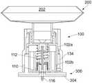
在某些实施例中,可收缩的壳体包括上壳体部分和下壳体部分,上壳体部分可以相对于下壳体部分沿着中心纵向轴线轴向移动。因此,上壳体部分可以相对于下壳体部分收缩。在一些示例中,使上壳体部分相对于下壳体部分收缩导致空心针刺穿上壳体部分的可刺穿密闭密封件。In certain embodiments, the collapsible housing includes an upper housing portion and a lower housing portion, the upper housing portion being axially movable relative to the lower housing portion along a central longitudinal axis. Therefore, the upper housing part can be retracted relative to the lower housing part. In some examples, retracting the upper housing portion relative to the lower housing portion causes the hollow needle to pierce the pierceable hermetic seal of the upper housing portion.
在一些实施例中,可收缩的壳体的第一部分可以相对于可收缩的壳体的第二部分沿着在连接器的远端和近端之间延伸的中心轴线轴向移动或平移。因此,可以提供壳体的可移动部分和壳体的固定部分。In some embodiments, the first portion of the collapsible housing can move or translate axially relative to the second portion of the collapsible housing along a central axis extending between the distal and proximal ends of the connector. Thus, a movable part of the housing and a fixed part of the housing can be provided.
在某些实施例中,外套筒可以允许上壳体部分相对于下壳体部分进行收缩或致动。In certain embodiments, the outer sleeve may allow retraction or actuation of the upper housing portion relative to the lower housing portion.
因此,外套筒可以被视为形成致动机构的一部分。Thus, the outer sleeve can be considered to form part of the actuating mechanism.
或者,在某些实施例中,可收缩的壳体包括上壳体部分和下壳体部分,下壳体部分可以相对于上壳体部分沿着中心纵向轴线轴向移动。因此,下壳体部分可以相对于上壳体部分收缩。在一些示例中,使下壳体部分相对于上壳体部分收缩导致空心针刺穿下壳体部分的可刺穿密闭密封件。Alternatively, in some embodiments, the collapsible housing includes an upper housing portion and a lower housing portion, the lower housing portion being axially movable relative to the upper housing portion along a central longitudinal axis. Therefore, the lower housing part can be retracted relative to the upper housing part. In some examples, retracting the lower housing portion relative to the upper housing portion causes the hollow needle to pierce the pierceable hermetic seal of the lower housing portion.
进一步可选地,在某些实施例中,可收缩的壳体包括上壳体部分和下壳体部分,下壳体部分可以相对于上壳体部分沿着中心纵向轴线轴向移动,并且上壳体部分可以相对于下壳体部分沿着中心纵向轴线轴向移动。因此,下壳体部分和上壳体部分中的每一个都可以相对于彼此收缩。在一些示例中,使下壳体部分相对于上壳体部分收缩以及使上壳体部分相对于下壳体部分收缩,导致空心针刺穿上壳体部分的可刺穿密闭密封件和下壳体部分的可刺穿密闭密封件。密封件的循序刺穿可以由收缩的顺序来控制。Further optionally, in some embodiments, the collapsible housing includes an upper housing portion and a lower housing portion, the lower housing portion being axially movable relative to the upper housing portion along a central longitudinal axis, and the upper housing portion The housing portion is axially movable relative to the lower housing portion along a central longitudinal axis. Thus, each of the lower housing part and the upper housing part can be retracted relative to each other. In some examples, retracting the lower housing portion relative to the upper housing portion and retracting the upper housing portion relative to the lower housing portion causes the hollow needle to pierce the pierceable seal of the upper housing portion and the lower housing A pierceable hermetic seal for the body portion. The sequential piercing of the seal can be controlled by the order of contractions.
在某些实施例中,上壳体部分包括至少一个可致动凸耳,该可致动凸耳被构造为沿着中心纵向轴线移动上壳体部分,该上壳体部分的至少一个可致动凸耳至少部分地、或大部分地或完全地穿过外套筒的至少一个狭槽突出。也就是说,在一些实施例中,外套筒进一步包括至少一个狭槽,上部壳体的可致动凸耳至少部分穿过该狭槽突出。In certain embodiments, the upper housing portion includes at least one actuatable lug configured to move the upper housing portion along the central longitudinal axis, at least one of the upper housing portions being actuatable The movable lug protrudes at least partially, or mostly or completely through the at least one slot of the outer sleeve. That is, in some embodiments, the outer sleeve further includes at least one slot through which the actuatable lug of the upper housing protrudes at least partially.
这提供了连接器适于自动化致动的优点。因此,连接器有利地适于自动化的细胞和/或基因治疗制造过程。This provides the advantage that the connector is suitable for automated actuation. Accordingly, the connector is advantageously suitable for automated cell and/or gene therapy manufacturing processes.
在一些实施例中,上壳体部分包括多个可致动凸耳。在一些实施例中,外套筒包括多个狭槽。在具体实施例中,每个可致动凸耳至少部分地、或大部分地或完全地穿过多个狭槽中的一个突出。In some embodiments, the upper housing portion includes a plurality of actuatable lugs. In some embodiments, the outer sleeve includes a plurality of slots. In particular embodiments, each actuatable lug protrudes at least partially, or mostly or completely through one of the plurality of slots.
在一些实施例中,上壳体部分包括一对直径相对的可致动凸耳。在一些实施例中,外套筒包括一对直径相对的狭槽。在具体实施例中,每个可致动凸耳至少部分穿过一对狭槽中的一个突出。In some embodiments, the upper housing portion includes a pair of diametrically opposed actuatable lugs. In some embodiments, the outer sleeve includes a pair of diametrically opposed slots. In particular embodiments, each actuatable lug protrudes at least partially through one of the pair of slots.
在一些实施例中,上壳体部分的可致动凸耳具有圆形或十字形(即十字架形)的横截面。In some embodiments, the actuatable lugs of the upper housing portion have a circular or cruciform (ie, cruciform) cross-section.
在一些实施例中,上壳体部分包括至少一个肋。在一些实施例中,上壳体部分包括一对肋。在一些实施例中,上壳体部分包括一对肋,每个肋设置在上壳体部分的可致动凸耳的任一侧。在特定实施例中,上壳体部分的所述肋或每个肋可以被构造和布置成与外套筒上的一个或更多个相应凹部配合。在其他实施例中,上壳体部分的所述肋或每个肋可以被构造和布置成与外套筒的内壁摩擦接合。In some embodiments, the upper housing portion includes at least one rib. In some embodiments, the upper housing portion includes a pair of ribs. In some embodiments, the upper housing portion includes a pair of ribs, each rib being disposed on either side of an actuatable lug of the upper housing portion. In certain embodiments, the or each rib of the upper housing portion may be constructed and arranged to mate with one or more corresponding recesses on the outer sleeve. In other embodiments, the or each rib of the upper housing portion may be constructed and arranged to frictionally engage the inner wall of the outer sleeve.
这提供了这样的优点,即防止上壳体部分的旋转移动,特别是在外套筒内的旋转移动。因此,空心针以基本竖直或纵向延伸的方式被保持。以这种方式,在使用期间使空心针基本上或完全地轴向移动,而不是在致动期间相对于可刺穿密封件形成一定角度。因此,可以实现一致的穿刺动作。This provides the advantage of preventing rotational movement of the upper housing part, especially within the outer sleeve. Thus, the hollow needle is held in a substantially vertical or longitudinal extension. In this way, the hollow needle is moved substantially or completely axially during use, rather than at an angle relative to the pierceable seal during actuation. Therefore, a consistent puncturing action can be achieved.
在一些实施例中,下壳体部分包括至少一个向外延伸的凸缘。向外延伸的凸缘可以从下壳体部分的外表面向外(即远离下壳体部分的中心纵向轴线)延伸。在一些实施例中,下壳体部分包括一对向外延伸的凸缘。在一些实施例中,这对向外延伸的凸缘是直径相对的。在一些实施例中,所述向外延伸的一个或更多个凸缘或每个向外延伸的凸缘可以被构造和布置成接收在外套筒的一个或更多个相应狭槽中。In some embodiments, the lower housing portion includes at least one outwardly extending flange. The outwardly extending flange may extend outwardly from the outer surface of the lower housing portion (ie away from the central longitudinal axis of the lower housing portion). In some embodiments, the lower housing portion includes a pair of outwardly extending flanges. In some embodiments, the pair of outwardly extending flanges are diametrically opposed. In some embodiments, the or each outwardly extending flange may be constructed and arranged to be received in one or more corresponding slots of the outer sleeve.
这提供了这样的优点,即下壳体部分例如相对于上壳体部分以静止的方式固定地保持在外套筒上。因此,可以确保更可靠地致动连接器。This provides the advantage that the lower housing part is held stationary on the outer sleeve, eg relative to the upper housing part, in a stationary manner. Therefore, a more reliable actuation of the connector can be ensured.
在某些实施例中,致动机构包括可操作地联接到空心针上的套环,该套环包括至少一个可致动凸耳,该可致动凸耳被构造为沿着中心纵向轴线移动套环,该套环的至少一个可致动凸耳至少部分穿过外套筒的至少一个狭槽突出。也就是说,在一些实施例中,外套筒进一步包括至少一个狭槽,套环的可致动凸耳至少部分穿过该狭槽突出。这样的至少一个狭槽可以与上壳体部分的可致动凸耳至少部分从中突出的至少一个狭槽不同或相同,即用于套环的可致动凸耳和上壳体部分的可致动凸耳的单独狭槽或一体狭槽。In certain embodiments, the actuation mechanism includes a collar operably coupled to the hollow needle, the collar including at least one actuatable lug configured to move along a central longitudinal axis A collar having at least one actuatable lug protruding at least partially through at least one slot of the outer sleeve. That is, in some embodiments, the outer sleeve further includes at least one slot through which the actuatable lug of the collar protrudes at least partially. Such at least one slot may be different or identical to at least one slot from which the actuatable lug of the upper housing part protrudes at least partially, ie the actuatable lug for the collar and the actuatable lug of the upper housing part Separate slots or integral slots for the moving lugs.
在一些实例中,套环的轴向平移以及由此空心针沿着中心纵向轴线朝向近端的轴向平移,导致空心针刺穿下壳体部分的可刺穿密闭密封件。In some instances, axial translation of the collar, and thus of the hollow needle toward the proximal end along the central longitudinal axis, causes the hollow needle to pierce the pierceable hermetic seal of the lower housing portion.
这提供了这样的优点,即连接器可以由自动化系统以顺序方式致动。此外,这提供了这样的优点,即刺穿的顺序方式可以由自动化系统来控制。此外,这种连接器的使用及其密封件的刺穿更不容易受到人为错误的影响。This provides the advantage that the connectors can be actuated in a sequential manner by the automated system. Furthermore, this provides the advantage that the sequential manner of piercing can be controlled by an automated system. Furthermore, the use of such connectors and the piercing of their seals are less susceptible to human error.
在一些实施例中,套环的可致动凸耳具有圆形或十字形(即十字架形)的横截面。In some embodiments, the actuatable lugs of the collar have a circular or cruciform (ie, cruciform) cross-section.
在一些实施例中,套环包括多个可致动凸耳。在一些实施例中,外套筒包括多个狭槽。在具体实施例中,每个可致动凸耳至少部分地、或大部分地或完全地穿过多个狭槽中的一个突出。In some embodiments, the collar includes a plurality of actuatable lugs. In some embodiments, the outer sleeve includes a plurality of slots. In particular embodiments, each actuatable lug protrudes at least partially, or mostly or completely through one of the plurality of slots.
在一些实施例中,套环包括一对直径相对的可致动凸耳。在一些实施例中,外套筒包括一对直径相对的狭槽。在具体实施例中,套环的每个可致动凸耳至少部分地、或大部分地或完全地穿过一对狭槽中的一个突出。In some embodiments, the collar includes a pair of diametrically opposed actuatable lugs. In some embodiments, the outer sleeve includes a pair of diametrically opposed slots. In particular embodiments, each actuatable lug of the collar protrudes at least partially, or mostly or completely through one of the pair of slots.
在具体实施例中,外套筒包括第一组多个狭槽,每个狭槽被构造和布置成使得上壳体部分的可致动凸耳至少部分地、或大部分地或完全地从该狭槽中突出,并且外套筒包括第二组多个狭槽,每个狭槽被构造和布置成使得套环的可致动凸耳至少部分地、或大部分地或完全地从该狭槽中突出。In particular embodiments, the outer sleeve includes a first set of a plurality of slots, each slot constructed and arranged such that the actuatable lugs of the upper housing portion are at least partially, or mostly or completely removed from the Projecting in the slot, and the outer sleeve includes a second plurality of slots, each slot constructed and arranged such that the actuatable lugs of the collar are at least partially, or mostly, or completely removed from the slot. protruding from the slot.
也就是说,在某些实施例中,上壳体部分的可致动凸耳有不同的狭槽,并且套环的可致动凸耳有不同的狭槽。在一些示例中,第一组多个狭槽中的每个狭槽可以围绕外套筒间隔开近似120°。在一些示例中,第二组多个狭槽中的每个狭槽可以围绕外套筒间隔开120°并且相对于第一组多个狭槽偏移。That is, in some embodiments, the actuatable lugs of the upper housing portion have different slots, and the actuatable lugs of the collar have different slots. In some examples, each slot in the first plurality of slots may be spaced approximately 120° apart around the outer sleeve. In some examples, each slot in the second plurality of slots may be spaced 120° about the outer sleeve and offset relative to the first plurality of slots.
这提供了这样的优点,即可以提供单独的致动机构,用于接合不同的可致动凸耳。This provides the advantage that separate actuation mechanisms can be provided for engaging the different actuatable lugs.
在具体实施例中,外套筒包括第一狭槽以及与第一狭槽直径相对的第二狭槽,其中套环的一对可致动凸耳中的一个凸耳和上壳体部分的一对可致动凸耳中的一个凸耳至少部分地、或大部分地或完全地穿过第一狭槽突出,并且其中套环的一对可致动凸耳中的另一个凸耳和上壳体部分的一对可致动凸耳中的另一个凸耳至少部分地、或大部分地或完全地穿过第二狭槽突出。In particular embodiments, the outer sleeve includes a first slot and a second slot diametrically opposite the first slot, wherein one of the pair of actuatable lugs of the collar and the upper housing portion One of the pair of actuatable lugs protrudes at least partially, or mostly or completely through the first slot, and wherein the other lug of the pair of actuatable lugs of the collar and The other of the pair of actuatable lugs of the upper housing part protrudes at least partially, or mostly or completely through the second slot.
也就是说,第一狭槽包括至少部分从其中突出的套环的可致动凸耳和上壳体部分的可致动凸耳。同样地,第二狭槽包括至少部分地从其中突出的套环的可致动凸耳和上壳体部分的可致动凸耳。That is, the first slot includes an actuatable lug of the collar and an actuatable lug of the upper housing portion at least partially protruding therefrom. Likewise, the second slot includes an actuatable lug of the collar and an actuatable lug of the upper housing portion at least partially protruding therefrom.
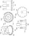
具体地说,外套筒包括侧壁,该侧壁具有第一狭槽以及与该第一狭槽直径相对的第二狭槽,第一狭槽接收上壳体部分的第一可致动凸耳和套环的第一可致动凸耳,第二狭槽接收上壳体部分的第二可致动凸耳和套环的第二可致动凸耳。Specifically, the outer sleeve includes a side wall having a first slot and a second slot diametrically opposite the first slot, the first slot receiving the first actuatable protrusion of the upper housing portion The ear and the first actuatable lug of the collar and the second slot receive the second actuatable lug of the upper housing portion and the second actuatable lug of the collar.
更具体地说,在某些实施例中,外套筒包括具有第一狭槽和第二狭槽的侧壁,该第二狭槽与该第一狭槽直径相对;上壳体部分包括从该上壳体部分的主体延伸的第一可致动凸耳以及从该上壳体部分的主体延伸的第二可致动凸耳,该第一可致动凸耳和该第二可致动凸耳彼此直径相对;套环包括从该套环的外壁延伸的第一可致动凸耳以及从该套环的外壁延伸的第二可致动凸耳,该第一可致动凸耳和该第二可致动凸耳彼此直径相对;其中上壳体的第一可致动凸耳和套环的第一可致动凸耳至少部分穿过外套筒的第一狭槽突出,并且其中上壳体的第二可致动凸耳和套环的第二可致动凸耳至少部分穿过外套筒的第二狭槽突出。More specifically, in certain embodiments, the outer sleeve includes a sidewall having a first slot and a second slot diametrically opposite the first slot; the upper housing portion includes a A first actuatable lug extending from the body of the upper housing portion and a second actuatable lug extending from the body of the upper housing portion, the first actuatable lug and the second actuatable lug The lugs are diametrically opposed to each other; the collar includes a first actuatable lug extending from an outer wall of the collar and a second actuatable lug extending from the outer wall of the collar, the first actuatable lug and the second actuatable lugs are diametrically opposed to each other; wherein the first actuatable lug of the upper housing and the first actuatable lug of the collar protrude at least partially through the first slot of the outer sleeve, and wherein the second actuatable lug of the upper housing and the second actuatable lug of the collar protrude at least partially through the second slot of the outer sleeve.
这提供了这样的优点,即可以利用占地面积较小的致动机构。This provides the advantage that a smaller footprint actuation mechanism can be utilized.
通常,外套筒中的一个或更多个狭槽可以提供通向上壳体部分和/或套环的可致动凸耳的入口。该一个或更多个狭槽可以允许使用者访问(即手动访问)或者允许机器人访问(即自动化访问)。Typically, one or more slots in the outer sleeve may provide access to the actuatable lugs of the upper housing portion and/or the collar. The one or more slots may allow user access (ie manual access) or robotic access (ie automated access).
在某些实施例中,外套筒包括侧壁,该侧壁优选基本上呈柱形的侧壁。在一些实施例中,一个或更多个狭槽(即第一狭槽或第一组多个狭槽和/或第二狭槽或第二组多个狭槽)形成在侧壁内。外套筒可以由两个半管部分形成,这两个半管部分可操作地联接在一起以形成外套筒。两个半管部分可以彼此焊接、粘合、夹持等。In certain embodiments, the outer sleeve includes a side wall, preferably a substantially cylindrical side wall. In some embodiments, one or more slots (ie, the first slot or the first plurality of slots and/or the second slot or the second plurality of slots) are formed in the sidewall. The outer sleeve may be formed from two half-pipe portions operably coupled together to form the outer sleeve. The two half-pipe sections may be welded, glued, clamped, etc. to each other.
在某些实施例中,外套筒包括前壁、后壁以及邻接前壁和后壁的侧壁。可能有两个侧壁。在一些示例中,一个或更多个狭槽(即第一狭槽或第一组多个狭槽和/或第二狭槽或第二组多个狭槽)设置在所述侧壁或每个侧壁内。外套筒可以进一步包括保护壁,该保护壁形成外套筒的抓握区域,该保护壁在一个或更多个狭槽上方延伸。以这种方式,保护壁被构造为防止手动接近外套筒内的部件,同时允许连接器的自动化致动。保护壁可以是滚花的或类似的,以增强使用者的抓握。In certain embodiments, the outer sleeve includes a front wall, a rear wall, and side walls adjoining the front and rear walls. There may be two side walls. In some examples, one or more slots (ie, a first slot or a first plurality of slots and/or a second slot or a second plurality of slots) are provided in the sidewall or each inside a side wall. The outer sleeve may further include a protective wall forming a gripping area for the outer sleeve, the protective wall extending over the one or more slots. In this manner, the protective wall is configured to prevent manual access to components within the outer sleeve, while allowing automated actuation of the connector. The protective wall may be knurled or similar to enhance the user's grip.
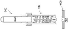
在某些实施例中,设置至少一个防护罩(gaiter)来包围空心针。在一些示例中,设置单个柔性防护罩来包围空心针和套环。在其他示例中,设置第一柔性防护罩来包围空心针的第一部分,并且设置第二柔性防护罩来包围空心针的第二部分。第一柔性防护罩可以从套环的上表面延伸到上壳体部分的下表面。第二柔性防护罩可以从套环的下表面延伸到下壳体部分的上表面。该至少一个防护罩可以将空心针包围在灭菌的或无菌的环境内。因此,该至少一个防护罩可以在灭菌的条件下密封其中的空心针。因此,该至少一个防护罩可以密闭密封其中的空心针。In certain embodiments, at least one guard is provided to surround the hollow needle. In some examples, a single flexible shield is provided to surround the hollow needle and the collar. In other examples, a first flexible shield is provided to surround a first portion of the hollow needle, and a second flexible shield is provided to surround a second portion of the hollow needle. The first flexible shield may extend from the upper surface of the collar to the lower surface of the upper housing portion. The second flexible shield may extend from the lower surface of the collar to the upper surface of the lower housing portion. The at least one shield can enclose the hollow needle within a sterile or sterile environment. Thus, the at least one shield can seal the hollow needle therein under sterile conditions. Thus, the at least one shield can hermetically seal the hollow needle therein.
这提供了这样的优点,即在空心针周围确保灭菌的环境。此外,可以防止针刺受伤。This provides the advantage of ensuring a sterile environment around the hollow needle. In addition, needle stick injuries can be prevented.
在某些实施例中,空心针是双头针。In certain embodiments, the hollow needle is a double ended needle.
这提供了这样的优点,即可以轻松地连接两个接收件(可选地包括隔膜)。This provides the advantage that the two receivers (optionally including the membrane) can be easily connected.
在某些实施例中,连接器的壳体的近端和远端都包括可刺穿密封件。In certain embodiments, both the proximal and distal ends of the housing of the connector include pierceable seals.
在某些实施例中,双头空心针安装在壳体内,并且其中当将该双头空心针偏置安装在壳体内时,该双头空心针的每一端面向壳体的近端或远端的可刺穿密封件。In certain embodiments, the double ended hollow needle is mounted within the housing, and wherein each end of the double ended hollow needle faces either the proximal end or the distal end of the housing when the double ended hollow needle is offset mounted within the housing pierceable seal.
这提供了这样的优点,即空心针可以保持在灭菌的或无菌的环境中。This provides the advantage that the hollow needle can be kept in a sterile or sterile environment.
在某些实施例中,双头空心针的第一端(即邻近壳体的近端的一端)包括笔尖闭合端和邻近笔尖闭合端的端口。这种端部可以被称为Whitacre端部。In certain embodiments, the first end of the double-ended hollow needle (ie, the end adjacent to the proximal end of the housing) includes a closed end of the nib and a port adjacent to the closed end of the nib. Such ends may be referred to as Whitacre ends.
这提供了这样的优点,即双头针的第一端可以重复刺穿可重新密封的可刺穿密封件(例如连接器、容器、生物反应器等的密封件)并且确保这种密封件的可重新密封性。因此,保持了灭菌的环境。This provides the advantage that the first end of the double ended needle can repeatedly pierce resealable pierceable seals (eg, seals of connectors, vessels, bioreactors, etc.) and ensures that the Resealability. Therefore, a sterile environment is maintained.
在某些实施例中,双头空心针的第二端(即邻近壳体的远端的一端)包括开口端,比如斜切的开口端。In certain embodiments, the second end of the double-ended hollow needle (ie, the end adjacent to the distal end of the housing) includes an open end, such as a chamfered open end.
这提供了这样的优点,即双头针的第二端可以轻松地刺穿可刺穿密封件。具体地说,第二端刺穿可刺穿密封件需要的致动力可能较小。This provides the advantage that the second end of the double ended needle can easily pierce the pierceable seal. Specifically, the actuation force required for the second end to pierce the pierceable seal may be less.
在某些实施例中,连接器进一步包括致动机构,以使双头空心针能够刺穿近端和远端处的可刺穿密封件。In certain embodiments, the connector further includes an actuation mechanism to enable the double-ended hollow needle to pierce the pierceable seals at the proximal and distal ends.
在某些实施例中,致动机构包括外套筒,该外套筒被构造为使得双头空心针能够刺穿可刺穿密封件以连接到第一接收件和第二接收件上。In certain embodiments, the actuation mechanism includes an outer sleeve configured to enable the double-ended hollow needle to pierce the pierceable seal to connect to the first and second receivers.
这提供了这样的优点,即在一些实施例中,空心针可以在灭菌的条件下连接到壳体每一端处的接收件器或与其连通。This provides the advantage that, in some embodiments, the hollow needle can be connected to or communicated with the receiver at each end of the housing under sterile conditions.
在一些实施例中,连接器进一步包括外套筒。在一些实施例中,连接器的壳体包括外套筒。在一些实施例中,致动机构包括外套筒。外套筒可以位于连接器的壳体上。外套筒可以位于连接器壳体上,位于连接器的壳体的近端和远端之间。在一些实施例中,外套筒是可旋转的。在一些实施例中,外套筒可以在两个方向上旋转。In some embodiments, the connector further includes an outer sleeve. In some embodiments, the housing of the connector includes an outer sleeve. In some embodiments, the actuation mechanism includes an outer sleeve. The outer sleeve may be located on the housing of the connector. An outer sleeve may be located on the connector housing between the proximal and distal ends of the housing of the connector. In some embodiments, the outer sleeve is rotatable. In some embodiments, the outer sleeve can rotate in both directions.
在一些实施例中,外套筒被构造为使得外套筒的至少部分旋转引起空心针的轴向平移,以刺穿位于连接器的壳体的端部处的至少一个可刺穿密封件。例如,这可以是位于壳体的近端或远端处的可刺穿密封件。In some embodiments, the outer sleeve is configured such that at least partial rotation of the outer sleeve causes axial translation of the hollow needle to pierce at least one pierceable seal at the end of the housing of the connector. For example, this could be a pierceable seal at the proximal or distal end of the housing.
在一些实施例中,外套筒被构造为使得外套筒的至少部分旋转引起可刺穿密封件的轴向平移,以接触空心针,从而刺穿位于连接器的壳体的端部处的可刺穿密封件。例如,这可以是位于壳体的近端或远端处的可刺穿密封件。In some embodiments, the outer sleeve is configured such that at least partial rotation of the outer sleeve causes axial translation of the pierceable seal to contact the hollow needle to pierce the pierce at the end of the housing of the connector Pierceable seal. For example, this could be a pierceable seal at the proximal or distal end of the housing.
在一些实施例中,外套筒被构造为使得外套筒的部分旋转引起壳体的近端和远端处的可刺穿密封件的轴向平移,以接触空心针,从而刺穿连接器的壳体的近端和远端处的可刺穿密封件。In some embodiments, the outer sleeve is configured such that partial rotation of the outer sleeve causes axial translation of the pierceable seals at the proximal and distal ends of the housing to contact the hollow needle to pierce the connector pierceable seals at the proximal and distal ends of the housing.
在某些实施例中,外套筒被构造为使得外套筒的至少部分旋转引起空心针的轴向平移,以刺穿每个可刺穿密封件,从而连接到第一接收件和第二接收件或与第一接收件和第二接收件连通。In certain embodiments, the outer sleeve is configured such that at least partial rotation of the outer sleeve causes axial translation of the hollow needle to pierce each pierceable seal to connect to the first receiver and the second The receiver is either in communication with the first receiver and the second receiver.
在具体实施例中,外套筒被构造为使得外套筒的至少部分旋转引起空心针的轴向平移和可刺穿密封件的轴向平移。In particular embodiments, the outer sleeve is configured such that at least partial rotation of the outer sleeve causes axial translation of the hollow needle and axial translation of the pierceable seal.
在一些具体实施例中,其中连接器包括壳体的近端处的可刺穿密封件和壳体的远端处的可刺穿密封件,外套筒可以被构造为使得外套筒的至少部分旋转引起空心针的轴向平移和可刺穿密封件的轴向平移,使得空心针刺穿连接器的壳体的远端处的可刺穿密封件和近端处的可刺穿密封件。In some embodiments wherein the connector includes a pierceable seal at the proximal end of the housing and a pierceable seal at the distal end of the housing, the outer sleeve can be configured such that at least the outer sleeve has at least a pierceable seal at its distal end. Partial rotation causes axial translation of the hollow needle and axial translation of the pierceable seal such that the hollow needle pierces the pierceable seal at the distal end and the pierceable seal at the proximal end of the housing of the connector .
使外套筒部分旋转以移动空心针或可刺穿密封件有利地使得能够轻松刺穿一个或更多个可刺穿密封件。有利的是,这可以以流体密封的方式进行。有利的是,这可以以灭菌的方式进行。Rotating the outer sleeve portion to move the hollow needle or pierceable seal advantageously enables easy piercing of one or more pierceable seals. Advantageously, this can be done in a fluid-tight manner. Advantageously, this can be done in a sterile manner.
在某些实施例中,外套筒被构造为使得外套筒的至少部分旋转引起双头空心针的轴向平移,以刺穿每个可刺穿密封件,从而连接到第一接收件和第二接收件或与第一接收件和第二接收件连通。In certain embodiments, the outer sleeve is configured such that at least partial rotation of the outer sleeve causes axial translation of the double-ended hollow needle to pierce each pierceable seal to connect to the first receiver and The second receiver is either in communication with the first receiver and the second receiver.
这提供了这样的优点,即连接器可以手动致动,而不存在针刺受伤的风险。This provides the advantage that the connector can be actuated manually without the risk of needle stick injuries.
在一些实施例中,外套筒被构造为使得外套筒的至少部分轴向平移引起空心针的轴向平移,以刺穿位于连接器的壳体的端部处的至少一个可刺穿密封件。例如,这可以是位于壳体的近端或远端处的可刺穿密封件。In some embodiments, the outer sleeve is configured such that at least partial axial translation of the outer sleeve causes axial translation of the hollow needle to pierce at least one pierceable seal at the end of the housing of the connector piece. For example, this could be a pierceable seal at the proximal or distal end of the housing.
在一些实施例中,外套筒被构造为使得外套筒的至少部分轴向平移引起可刺穿密封件的轴向平移,以接触空心针,从而刺穿位于连接器的壳体的端部处的可刺穿密封件。例如,这可以是位于壳体的近端或远端处的可刺穿密封件。In some embodiments, the outer sleeve is configured such that at least partial axial translation of the outer sleeve causes axial translation of the pierceable seal to contact the hollow needle to pierce the end located in the housing of the connector pierceable seal. For example, this could be a pierceable seal at the proximal or distal end of the housing.
在一些实施例中,外套筒被构造为使得外套筒的部分轴向平移引起壳体的近端和远端处的可刺穿密封件的轴向平移,以接触空心针,从而刺穿连接器的壳体的近端和远端处的可刺穿密封件。In some embodiments, the outer sleeve is configured such that axial translation of a portion of the outer sleeve causes axial translation of the pierceable seals at the proximal and distal ends of the housing to contact the hollow needle for piercing Pierceable seals at the proximal and distal ends of the housing of the connector.
在某些实施例中,外套筒被构造为使得外套筒的至少部分轴向平移引起空心针的轴向平移,以刺穿每个可刺穿密封件,从而连接到第一接收件和第二接收件或与第一接收件和第二接收件连通。In certain embodiments, the outer sleeve is configured such that at least partial axial translation of the outer sleeve causes axial translation of the hollow needle to pierce each pierceable seal to connect to the first receiver and The second receiver is either in communication with the first receiver and the second receiver.
在具体实施例中,外套筒被构造为使得外套筒的至少部分轴向平移引起空心针的轴向平移和可刺穿密封件的轴向平移。In particular embodiments, the outer sleeve is configured such that at least partial axial translation of the outer sleeve causes axial translation of the hollow needle and axial translation of the pierceable seal.
在一些具体实施例中,其中连接器包括壳体的近端处的可刺穿密封件和壳体的远端处的可刺穿密封件,外套筒可以被构造为使得外套筒的至少部分轴向平移引起空心针的轴向平移和可刺穿密封件的轴向平移,使得空心针刺穿连接器的壳体的远端处的可刺穿密封件和近端处的可刺穿密封件。In some embodiments wherein the connector includes a pierceable seal at the proximal end of the housing and a pierceable seal at the distal end of the housing, the outer sleeve may be configured such that at least the outer sleeve has at least a pierceable seal at its distal end. Partial axial translation causes axial translation of the hollow needle and axial translation of the pierceable seal such that the hollow needle pierces the pierceable seal at the distal end and the pierceable seal at the proximal end of the housing of the connector Seals.
使外套筒部分轴向平移以移动空心针或可刺穿密封件有利地使得能够轻松刺穿一个或更多个可刺穿密封件。此外,外套筒的轴向平移确保这种连接器更适合自动化加工。有利的是,这可以以流体密封的方式进行。有利的是,这可以以灭菌的方式进行。Axial translation of the outer sleeve portion to move the hollow needle or pierceable seal advantageously enables easy piercing of one or more pierceable seals. In addition, the axial translation of the outer sleeve ensures that this connector is more suitable for automated processing. Advantageously, this can be done in a fluid-tight manner. Advantageously, this can be done in a sterile manner.
在某些实施例中,外套筒被构造为使得外套筒的至少部分轴向平移引起双头空心针的轴向平移,以刺穿每个可刺穿密封件,从而连接到第一接收件和第二接收件或与第一接收件和第二接收件连通。In certain embodiments, the outer sleeve is configured such that at least partial axial translation of the outer sleeve causes axial translation of the double-ended hollow needle to pierce each pierceable seal to connect to the first receiver and the second receiver or communicate with the first receiver and the second receiver.
这提供了这样的优点,即连接器可以手动致动,而不存在针刺受伤的风险。This provides the advantage that the connector can be actuated manually without the risk of needle stick injuries.
在某些实施例中,连接器进一步包括可释放的附接机构。连接器可以可释放地附接到例如一个或更多个容器、端口、连接器或生物反应器。在一些实施例中,可释放的附接机构包括螺纹。在一些实施例中,连接器包括螺纹,该螺纹与连接器可以可释放地附接到其上的相应元件上的螺纹相对应。在一些实施例中,壳体包括可释放的连接机构。在一些实施例中,壳体在壳体的近端处包括可释放的连接机构。在一些实施例中,壳体在壳体的远端处包括可释放的连接机构。在一些实施例中,连接器的外套筒包括可释放的附接机构。在一些实施例中,外套筒在外套筒的近端处包括可释放的连接机构。在一些实施例中,外套筒在外套筒的远端处包括可释放的连接机构。In certain embodiments, the connector further includes a releasable attachment mechanism. The connector can be releasably attached to, for example, one or more containers, ports, connectors or bioreactors. In some embodiments, the releasable attachment mechanism includes threads. In some embodiments, the connector includes threads that correspond to threads on corresponding elements to which the connector may be releasably attached. In some embodiments, the housing includes a releasable attachment mechanism. In some embodiments, the housing includes a releasable attachment mechanism at the proximal end of the housing. In some embodiments, the housing includes a releasable attachment mechanism at the distal end of the housing. In some embodiments, the outer sleeve of the connector includes a releasable attachment mechanism. In some embodiments, the outer sleeve includes a releasable attachment mechanism at the proximal end of the outer sleeve. In some embodiments, the outer sleeve includes a releasable attachment mechanism at the distal end of the outer sleeve.
在一些实施例中,可以旋转连接器,以将其可释放地附接到相应元件上。在一些实施例中,可以旋转相应元件,以将其可释放地附接到连接器上。In some embodiments, the connector can be rotated to releasably attach it to the corresponding element. In some embodiments, the corresponding element can be rotated to releasably attach it to the connector.
在某些实施例中,外套筒被构造为使得外套筒在连接器的外套筒的近端和相应接收件(例如,第二接收件)的一部分之间产生可释放的锁定接合。In certain embodiments, the outer sleeve is configured such that the outer sleeve creates a releasable locking engagement between a proximal end of the outer sleeve of the connector and a portion of a corresponding receiver (eg, a second receiver).
这提供了这样的优点,即使用者可以通过触觉、视觉或触视觉轻松识别连接器是否正确地连接到相应接收件。This provides the advantage that the user can easily identify, by touch, sight or touch, whether the connector is correctly connected to the corresponding receptacle.
在一些实施例中,外套筒包括螺纹。在一些实施例中,外套筒在外套筒的近端处包括螺纹。在一些实施例中,外套筒在外套筒的远端处包括螺纹。在一些实施例中,外套筒在外套筒的内表面上包括螺纹。In some embodiments, the outer sleeve includes threads. In some embodiments, the outer sleeve includes threads at the proximal end of the outer sleeve. In some embodiments, the outer sleeve includes threads at the distal end of the outer sleeve. In some embodiments, the outer sleeve includes threads on the inner surface of the outer sleeve.
在某些实施例中,空心针至少部分偏置安装在壳体内。In certain embodiments, the hollow needle is at least partially offset mounted within the housing.
这提供了这样的优点,即空心针被设置成可移动的,从而防止针刺受伤。有利的是,可以将空心针容纳在安全位置,但是该空心针在使用中能够移动以刺穿一个或更多个可刺穿密封件。This provides the advantage that the hollow needle is made movable, thereby preventing needle stick injuries. Advantageously, the hollow needle can be accommodated in a safe position, but which can be moved in use to pierce the one or more pierceable seals.
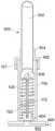
在某些实施例中,双头空心针通过偏置机构在朝向壳体的近端的方向上偏置。优选地,偏置机构是螺旋弹簧。螺旋弹簧可以在与双头空心针可操作联接的套环和上壳体部分之间延伸。In certain embodiments, the double-ended hollow needle is biased in a direction toward the proximal end of the housing by a biasing mechanism. Preferably, the biasing mechanism is a coil spring. A coil spring may extend between the collar operably coupled with the double-ended hollow needle and the upper housing portion.
这提供了这样的优点,即通过单个弹簧实现可刺穿密闭密封件的循序刺穿。This provides the advantage of enabling sequential piercing of the pierceable hermetic seal by a single spring.
在一些实施例中,上壳体部分可以包括至少一个可致动凸耳。该至少一个可致动凸耳可以延伸穿过连接器的外套筒的至少一个狭槽。在致动所述至少一个可致动凸耳时,导致上壳体部分相对于下壳体部分收缩,从而导致空心针刺穿下壳体部分内的可刺穿密闭密封件。进一步的致动导致弹簧压缩,从而随后导致刺穿上壳体部分的可刺穿密闭密封件。In some embodiments, the upper housing portion may include at least one actuatable lug. The at least one actuatable lug may extend through at least one slot of the outer sleeve of the connector. Upon actuation of the at least one actuatable lug, the upper housing portion is caused to retract relative to the lower housing portion, thereby causing the hollow needle to pierce the pierceable hermetic seal within the lower housing portion. Further actuation causes the spring to compress, which in turn causes the pierceable hermetic seal of the upper housing portion to pierce.
这提供了这样的优点,即可以容易且精确地控制循序刺穿。因此,该连接器适用于自动化。This provides the advantage that sequential piercings can be easily and precisely controlled. Therefore, the connector is suitable for automation.
在某些实施例中,双头空心针通过偏置机构在朝向壳体的远端的方向上偏置。优选地,偏置机构是螺旋弹簧。螺旋弹簧可以在与双头空心针可操作联接的套环和下壳体部分之间延伸。In certain embodiments, the double-ended hollow needle is biased in a direction toward the distal end of the housing by a biasing mechanism. Preferably, the biasing mechanism is a coil spring. A coil spring may extend between the collar and the lower housing portion operatively coupled to the double-ended hollow needle.
这提供了这样的优点,即通过单个弹簧实现可刺穿密闭密封件的循序刺穿。This provides the advantage of enabling sequential piercing of the pierceable hermetic seal by a single spring.
在一些实施例中,下壳体部分可以包括至少一个可致动凸耳。该至少一个可致动凸耳可以延伸穿过连接器的外套筒的至少一个狭槽。在致动所述至少一个可致动凸耳时,导致下壳体部分相对于上壳体部分收缩,从而导致空心针刺穿上壳体部分内的可刺穿密闭密封件。进一步的致动导致弹簧压缩,从而随后导致刺穿下壳体部分的可刺穿密闭密封件。In some embodiments, the lower housing portion may include at least one actuatable lug. The at least one actuatable lug may extend through at least one slot of the outer sleeve of the connector. Upon actuation of the at least one actuatable lug, the lower housing portion is caused to retract relative to the upper housing portion, thereby causing the hollow needle to pierce the pierceable hermetic seal within the upper housing portion. Further actuation causes the spring to compress, which in turn causes the pierceable hermetic seal of the lower housing portion to pierce.
这提供了这样的优点,即可以容易且精确地控制循序刺穿。因此,该连接器适用于自动化。This provides the advantage that sequential piercings can be easily and precisely controlled. Therefore, the connector is suitable for automation.
在某些实施例中,双头空心针通过第一偏置机构在朝向壳体的近端的方向上偏置,并且通过第二偏置机构在朝向壳体的远端的方向上偏置。In certain embodiments, the double-ended hollow needle is biased in a direction toward the proximal end of the housing by a first biasing mechanism, and is biased in a direction toward the distal end of the housing by a second biasing mechanism.
在某些实施例中,第一偏置机构提供第一偏置力,并且第二偏置机构提供第二偏置力,该第一偏置力和该第二偏置力近似相等。In certain embodiments, the first biasing mechanism provides a first biasing force and the second biasing mechanism provides a second biasing force, the first biasing force and the second biasing force being approximately equal.
这提供了这样的优点,即空心针可以几乎同时刺穿每个隔膜。This provides the advantage that the hollow needle can pierce each septum almost simultaneously.
在某些实施例中,第一偏置机构提供第一偏置力,并且第二偏置机构提供第二偏置力,该第一偏置力大于该第二偏置力。In certain embodiments, the first biasing mechanism provides a first biasing force, and the second biasing mechanism provides a second biasing force, the first biasing force being greater than the second biasing force.
这提供了这样的优点,即空心针可以首先刺穿第二隔膜,然后刺穿第一隔膜,从而提供隔膜的循序刺穿。This provides the advantage that the hollow needle can pierce the second septum first and then the first septum, thereby providing sequential piercing of the septum.
在某些实施例中,第一偏置机构提供第一偏置力,并且第二偏置机构提供第二偏置力,该第二偏置力大于该第一偏置力。In certain embodiments, the first biasing mechanism provides a first biasing force, and the second biasing mechanism provides a second biasing force that is greater than the first biasing force.
这提供了这样的优点,即空心针可以首先刺穿第一隔膜,然后刺穿第二隔膜,从而提供隔膜的循序刺穿。This provides the advantage that the hollow needle can pierce the first septum first and then the second septum, thereby providing sequential piercing of the septum.
在某些实施例中,第一偏置机构包括弹性或非弹性偏置机构。In certain embodiments, the first biasing mechanism includes a resilient or inelastic biasing mechanism.
在某些实施例中,第二偏置机构包括弹性或非弹性偏置机构。In certain embodiments, the second biasing mechanism comprises a resilient or inelastic biasing mechanism.
在某些实施例中,第一偏置机构或第二偏置机构或第一偏置机构和第二偏置机构包括螺旋弹簧或可变形弹性材料。In certain embodiments, the first biasing mechanism or the second biasing mechanism or the first biasing mechanism and the second biasing mechanism comprise a coil spring or a deformable elastic material.
在某些实施例中,双头空心针的第一端或第二端或第一端和第二端是斜切的。也就是说,在某些实施例中,双头空心针的第一端或第二端或第一端和第二端是斜切的。In certain embodiments, the first end or the second end or the first end and the second end of the double ended hollow needle are chamfered. That is, in certain embodiments, the first end or the second end or the first end and the second end of the double-ended hollow needle are beveled.
这提供了这样的优点,即流体可以直接连接到空心针的通孔中,从而确保材料例如从第一接收件完全转移到第二接收件。此外,可以减少或避免材料的溢出。此外,也可以引导材料(例如流体内的颗粒)通过空心针,使得材料可以在例如接收件之间高效且有效地转移。This provides the advantage that the fluid can be connected directly into the through hole of the hollow needle, thus ensuring a complete transfer of material, eg from the first receiver to the second receiver. Furthermore, spillage of material can be reduced or avoided. In addition, it is also possible to guide material (eg, particles within a fluid) through the hollow needle so that the material can be efficiently and effectively transferred, eg, between receivers.
在某些实施例中,壳体的远端可连接到第一接收件。在某些实施例中,壳体的近端可连接到第一接收件。In certain embodiments, the distal end of the housing can be connected to the first receiver. In certain embodiments, the proximal end of the housing can be connected to the first receiver.
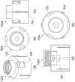
在某些实施例中,壳体的远端包括螺纹部分,该螺纹部分被构造为与第一接收件的相应螺纹部分接合。In certain embodiments, the distal end of the housing includes a threaded portion configured to engage a corresponding threaded portion of the first receiver.
在某些实施例中,螺纹部分包括具有中心截头锥形凹陷的隔膜密封件。In certain embodiments, the threaded portion includes a diaphragm seal with a central frustoconical depression.
这提供了这样的优点,即例如流体从接收件完全转移到连接器。此外,可以减少或避免材料的溢出。此外,也可以引导材料(例如流体内的固体颗粒)通过空心针,使得材料可以在例如接收件之间高效且有效地转移。This provides the advantage that, for example, the fluid is completely transferred from the receiver to the connector. Furthermore, spillage of material can be reduced or avoided. In addition, material (eg, solid particles within a fluid) can also be directed through the hollow needle, so that the material can be efficiently and effectively transferred, eg, between receivers.
在某些实施例中,螺纹部分包括防旋转构件。In certain embodiments, the threaded portion includes an anti-rotation member.
在某些实施例中,防旋转构件包括多个倾斜凹口,这些凹口被构造为与接收件上的多个相应凹口或裂口接合。In certain embodiments, the anti-rotation member includes a plurality of angled notches configured to engage a plurality of corresponding notches or slits on the receiver.
在某些实施例中,在壳体的所述端或每一端处的可刺穿密封件包括可刺穿的密闭密封件。In certain embodiments, the pierceable seal at the or each end of the housing comprises a pierceable hermetic seal.
这提供了这样的优点,即可以保持灭菌的或无菌的环境。This provides the advantage that a sterile or sterile environment can be maintained.
在一些实施例中,可刺穿密封件包括可刺穿密闭密封件。在一些实施例中,可刺穿密封件包括可重新密封的可刺穿密封件。在一些实施例中,可刺穿密封件包括可释放的可刺穿密闭密封件。在某些实施例中,可重新密封的可刺穿密闭密封件包括隔膜密封件。在一些实施例中,可重新密封的可刺穿密封件是自密封的。在一些实施例中,可重新密封的密闭密封件是自密封的。在一些实施例中,隔膜密封件是自密封的。在一些实施例中,隔膜密封件是自密封的隔膜密封件。在具体实施例中,可刺穿密封件是自密封的隔膜密封件。在具体实施例中,可刺穿密封件是自密封的密闭密封件。In some embodiments, the pierceable seal comprises a pierceable hermetic seal. In some embodiments, the pierceable seal comprises a resealable pierceable seal. In some embodiments, the pierceable seal comprises a releasable pierceable containment seal. In certain embodiments, the resealable pierceable seal includes a septum seal. In some embodiments, the resealable pierceable seal is self-sealing. In some embodiments, the resealable hermetic seal is self-sealing. In some embodiments, the diaphragm seal is self-sealing. In some embodiments, the diaphragm seal is a self-sealing diaphragm seal. In particular embodiments, the pierceable seal is a self-sealing septum seal. In particular embodiments, the pierceable seal is a self-sealing hermetic seal.
这提供了这样的优点,即可刺穿密闭密封件是可重新密封的,从而可以进行灭菌的或无菌的连接、断开和重新连接。This provides the advantage that the pierceable hermetic seal is resealable allowing sterile or sterile connection, disconnection and reconnection.
在某些实施例中,可刺穿密封件包括环形隔膜密封件。也就是说,可刺穿密封件包括形成为环形空间的隔膜密封件。该环形空间可以形成为包围圆形平坦基部的凸起环形部分。空心针可以被构造为刺穿圆形平坦基部。凸起环形部分可以被构造为与相应的可刺穿密封件(比如另一个环形隔膜密封件,例如面对面接合或接收在彼此的环形空间内的相应凸起环形部分,或平坦的隔膜密封件)接合(例如面对面接合)。In certain embodiments, the pierceable seal includes an annular diaphragm seal. That is, the pierceable seal includes a septum seal formed as an annular space. The annular space may be formed as a raised annular portion surrounding the circular flat base. The hollow needle can be configured to pierce the circular flat base. The raised annular portions may be configured to mate with a corresponding pierceable seal (such as another annular diaphragm seal, eg corresponding raised annular portions engaged face-to-face or received within an annular space of each other, or a flat diaphragm seal) Bonding (eg face-to-face bonding).
这提供了这样的优点,即环形凸起部分确保待刺穿的封闭区域内的无菌性。因此,可以保持灭菌的或无菌的环境。This provides the advantage that the annular raised portion ensures sterility in the closed area to be pierced. Thus, a sterile or sterile environment can be maintained.
在某些实施例中,连接器进一步包括覆盖件,该覆盖件设置在连接器的壳体的所述端或每一端处的可刺穿密封件上方。In certain embodiments, the connector further comprises a cover disposed over the pierceable seal at the or each end of the housing of the connector.
在某些实施例中,覆盖件包括可移除的灭菌纸密封件。In certain embodiments, the cover includes a removable sterilization paper seal.
在某些实施例中,连接器进一步包括灭菌的密封系统,该灭菌的密封系统包含灭菌膜和夹持部分,该灭菌膜设置在连接器的壳体的所述端或每一端处的可刺穿密闭密封件上方并且可操作地联接到夹持部分。In certain embodiments, the connector further comprises a sterile sealing system comprising a sterile membrane and a clamping portion, the sterile membrane being disposed on the or each end of the housing of the connector above the pierceable hermetic seal at and operably coupled to the gripping portion.
这提供了这样的优点,即在连接器和/或其他部件的处理和/或设定期间,灭菌膜确保在所述可刺穿密闭密封件或每个可刺穿密闭密封件处的灭菌环境。This provides the advantage that, during handling and/or setting of connectors and/or other components, the sterile membrane ensures sterilization at the or each pierceable seal. bacterial environment.
在某些实施例中,夹持部分可滑动地与连接器可操作地连接,使得夹持部分可以在第一构造和第二构造之间滑动,在第一构造中,灭菌膜设置在所述可刺穿密闭密封件或每个可刺穿密闭密封件上方,在第二构造中,灭菌膜从所述可刺穿密闭密封件或每个可刺穿密闭密封件上移除。In certain embodiments, the gripping portion is slidably operably connected to the connector such that the gripping portion can slide between a first configuration and a second configuration in which the sterilizing membrane is disposed at the over the or each pierceable seal, in the second configuration, the sterilizing film is removed from the or each pierceable seal.
这提供了这样的优点,即灭菌的密封系统可以在致动之前由自动化系统移除。因此,在使用期间确保灭菌的环境。This provides the advantage that the sterilized sealing system can be removed by the automated system prior to actuation. Therefore, a sterile environment is ensured during use.
在一些实施例中,夹持部分可滑动地与连接器的外套筒可操作地连接。In some embodiments, the clamping portion is slidably operably connected with the outer sleeve of the connector.
在具体实施例中,夹持部分包括轨道,该轨道被构造为可以在连接器的外套筒的轨道接收部分内滑动地可操作地接收。In particular embodiments, the clamping portion includes a track configured to be slidably operably received within the track receiving portion of the outer sleeve of the connector.
在具体实施例中,夹持部分包括至少一个(优选两个)突出肩部。在一些示例中,至少一个突出肩部被构造为由灭菌密封致动机构可操作地接合。更具体地说,在一些实施例中,灭菌密封致动机构被设置成向所述肩部或每个肩部上施加推动力。In particular embodiments, the gripping portion comprises at least one (preferably two) projecting shoulders. In some examples, the at least one protruding shoulder is configured to be operably engaged by the sterilization seal actuation mechanism. More specifically, in some embodiments, the sterile seal actuation mechanism is configured to apply a pushing force on the or each shoulder.
在具体实施例中,夹持部分至少包括定位元件,该定位元件被构造和布置成与外套筒的相应定位元件配合。在具体实施例中,夹持部分包括向外延伸的肋(比如纵向肋),该肋被构造和布置成与外套筒的相应肋或凹部配合(例如,摩擦接合)。In particular embodiments, the clamping portion includes at least positioning elements constructed and arranged to cooperate with corresponding positioning elements of the outer sleeve. In particular embodiments, the gripping portion includes outwardly extending ribs (eg, longitudinal ribs) that are constructed and arranged to mate (eg, frictionally engage) with corresponding ribs or recesses of the outer sleeve.
这提供了这样的优点,即夹持部分以及灭菌的密封系统在由灭菌密封致动机构接合之前保持在适当位置。This provides the advantage that the gripping portion as well as the sterile sealing system remain in place prior to engagement by the sterile sealing actuation mechanism.
在一些实施例中,灭菌膜包括灭菌纸密封件。优选地,灭菌薄膜包括灭菌聚乙烯薄膜。In some embodiments, the sterilization film includes a sterilization paper seal. Preferably, the sterile film comprises a sterile polyethylene film.
在一些实施例中,灭菌膜包括至少一个折叠,从而形成第一表面和第二表面,该第一表面被构造为向所述可刺穿密闭密封件或每个可刺穿密闭密封件提供灭菌密封,该第二表面被构造为与相应的灭菌膜匹配。可以提供任意数量的折叠。In some embodiments, the sterilizing film includes at least one fold forming a first surface and a second surface, the first surface being configured to provide the or each pierceable seal to the or each pierceable seal. A sterile seal, the second surface is configured to mate with a corresponding sterile membrane. Any number of folds can be provided.
在某些实施例中,连接器是灭菌的连接器。In certain embodiments, the connector is a sterilized connector.
在某些实施例中,通过旋转连接器,连接器的至少一端与接收件可拆卸地接合。In certain embodiments, at least one end of the connector is removably engaged with the receiver by rotating the connector.
在某些实施例中,空心针的第一端可以与第一接收件流体连接。也就是说,在空心针的第一端和第一接收件之间可以存在流体连接。In certain embodiments, the first end of the hollow needle may be in fluid connection with the first receiver. That is, there may be a fluid connection between the first end of the hollow needle and the first receiver.
在某些实施例中,空心针的第一端可以与第一接收件流体连接。In certain embodiments, the first end of the hollow needle may be in fluid connection with the first receiver.
在某些实施例中,致动机构作用壳体或空心针于,以形成通过可刺穿密封件的流体连通。In certain embodiments, the actuation mechanism acts on the housing or hollow needle to create fluid communication through the pierceable seal.
在某些实施例中,致动机构直接作用于壳体。在其他实施例中,致动机构直接作用于空心针。术语“直接”用于表示致动机构作用于对应的部件,而无需任何介入零件或中间零件。In some embodiments, the actuation mechanism acts directly on the housing. In other embodiments, the actuation mechanism acts directly on the hollow needle. The term "directly" is used to mean that the actuating mechanism acts on the corresponding component without any intervening or intermediate parts.
在一些实施例中,第一接收件可以包括一定体积,例如一定体积的流体。在一些实施例中,第二接收件可以包括一定体积,例如一定体积的流体。In some embodiments, the first receiver may comprise a volume, eg, a volume of fluid. In some embodiments, the second receiver may comprise a volume, eg, a volume of fluid.
本发明还提供了一种如本文所述的灭菌的密封系统。The present invention also provides a sterilized sealing system as described herein.
在一些实施例中,灭菌的密封系统可以包括夹持部分以及与该夹持部分可操作地联接的灭菌膜。In some embodiments, a sterile sealing system can include a grip portion and a sterile membrane operably coupled to the grip portion.
在一些实施例中,夹持部分可以包括前壁、后壁、邻接前壁和后壁的侧壁以及底壁。夹持部分可以包括由前壁、后壁、侧壁和底壁限定的空心主体。空心主体可以包括从前壁的内表面延伸到后壁的内表面的一个或更多个加强肋。前壁可以包括一个或更多个突出肩部,该肩部被构造为由灭菌密封致动机构接合。灭菌密封致动机构可以被构造为向所述突出肩部或每个突出肩部上提供推动力。底壁可以包括轴向突出构件,该轴向突出构件被构造和布置成与例如容器等的相应灭菌的密封系统的接收构件配合。夹持部分可以在一个侧壁或两个侧壁上包括一个或多个定位元件,比如如上所述的一个或更多个向外延伸的肋。In some embodiments, the gripping portion may include a front wall, a rear wall, side walls adjoining the front and rear walls, and a bottom wall. The clamping portion may comprise a hollow body defined by a front wall, a rear wall, side walls and a bottom wall. The hollow body may include one or more reinforcing ribs extending from the inner surface of the front wall to the inner surface of the rear wall. The front wall may include one or more protruding shoulders configured to be engaged by the sterilization seal actuation mechanism. The sterilization seal actuation mechanism may be configured to provide an urging force on the or each protruding shoulder. The bottom wall may include an axially projecting member constructed and arranged to cooperate with a receiving member of a corresponding sterilized sealing system such as a container or the like. The gripping portion may include one or more positioning elements on one or both side walls, such as one or more outwardly extending ribs as described above.
在一些实施例中,夹持部分可以包括一个或更多个轨道,该轨道被构造为可滑动地接收在连接器的相应轨道接收部分内。In some embodiments, the clamping portion may include one or more rails configured to be slidably received within corresponding rail receiving portions of the connector.
在一些实施例中,灭菌膜可以包括灭菌纸密封件。优选地,灭菌薄膜包括灭菌的聚乙烯薄膜。灭菌膜可以包括至少一个折叠,从而形成第一表面和第二表面,该第一表面被构造为灭菌密封到可刺穿密闭密封件(比如隔膜密封件)上,该第二表面被构造为与相应的灭菌膜匹配。In some embodiments, the sterilization film may include a sterilization paper seal. Preferably, the sterile film comprises a sterile polyethylene film. The sterile film may include at least one fold forming a first surface configured to be sterile sealed to a pierceable hermetic seal, such as a septum seal, and a second surface configured to To match with the corresponding sterilization membrane.
本发明还涉及一种从连接器移除灭菌的密封系统的方法。The present invention also relates to a method of removing a sterilized sealing system from a connector.
在第一步中,如本文所述,提供连接器和灭菌的密封系统。In a first step, as described herein, a connector and sterilized sealing system are provided.
在第二步中,提供灭菌密封致动机构。可选地,可以将灭菌致动机构设置为仪器(比如培养箱或壳体)的一部分。In a second step, a sterile seal actuation mechanism is provided. Alternatively, the sterilization actuation mechanism may be provided as part of an instrument such as an incubator or housing.
在第三步中,灭菌密封致动机构与灭菌的密封系统的夹持部分接合。可选地,灭菌密封致动机构与夹持部分的一个或更多个肩部接合。In a third step, the sterile seal actuation mechanism engages the gripping portion of the sterile seal system. Optionally, a sterile seal actuation mechanism engages one or more shoulders of the gripping portion.
在第四步中,灭菌密封致动机构向夹持部分施加力,以便从连接器上至少部分地移除灭菌的密封系统。可选地,所述力可以是推动力或拉力。In a fourth step, the sterile seal actuation mechanism applies a force to the gripping portion to at least partially remove the sterile seal system from the connector. Alternatively, the force may be a pushing force or a pulling force.
在第五步中,夹持部分的至少部分移除导致灭菌膜从可刺穿密闭密封件中的至少部分移除,从而暴露可刺穿密闭密封件的至少一部分(优选全部)。In a fifth step, the at least partial removal of the gripping portion results in at least partial removal of the sterilizing film from the pierceable seal, thereby exposing at least a portion (preferably all) of the pierceable seal.
本发明还提供了一种系统,包括:The present invention also provides a system, including:
-如本文所述的连接器;- a connector as described herein;
-与所述连接器的一端可拆卸联接的第一接收件,并且其中所述第一接收件连接到空心针的第一端;和- a first receiver detachably coupled to one end of the connector, and wherein the first receiver is connected to the first end of the hollow needle; and
-与所述连接器的一端可拆卸联接的第二接收件,并且其中所述第二接收件连接到空心针的第二端。- a second receiver detachably coupled to one end of the connector, and wherein the second receiver is connected to the second end of the hollow needle.
这提供了这样的优点,即第一接收件可以通过连接器与第二接收件连接、断开和重新连接。更具体地说,连接、断开和重新连接可以以灭菌的或无菌的方式来实现。此外,该系统可能更适合自动化过程并且可能更容易处理和使用。This provides the advantage that the first receptacle can be connected, disconnected and reconnected to the second receptacle via the connector. More specifically, connecting, disconnecting and reconnecting can be accomplished in a sterile or sterile manner. Furthermore, the system may be more suitable for automated processes and may be easier to handle and use.
在某些实施例中,第一接收件或第二接收件或第一接收件和第二接收件包括可刺穿密封件,该可刺穿密封件在连接器的壳体的所述端或每一端处与可刺穿密封件同轴对齐。In certain embodiments, the first receiver or the second receiver or the first receiver and the second receiver includes a pierceable seal at the end of the housing of the connector or Coaxially aligned with the pierceable seal at each end.
在某些实施例中,第一接收件或第二接收件或第一接收件和第二接收件的所述可刺穿密封件或每个可刺穿密封件包括可刺穿密闭密封件,并且其中壳体的所述可刺穿密封件或每个可刺穿密封件包括可刺穿密闭密封件。In certain embodiments, the or each pierceable seal of the first receiver or the second receiver or the first receiver and the second receiver comprises a pierceable containment seal, And wherein the or each pierceable seal of the housing comprises a pierceable hermetic seal.
在某些实施例中,一个或更多个可刺穿密闭密封件包括隔膜密封件。也就是说,在某些实施例中,第一接收件或第二接收件或第一接收件和第二接收件的所述可刺穿密封件或每个可刺穿密封件包括隔膜密封件。附加地或替代地,在某些实施例中,壳体的所述可刺穿密闭密封件或每个可刺穿密闭密封件包括隔膜密封件。In certain embodiments, the one or more pierceable seals include a septum seal. That is, in certain embodiments, the or each pierceable seal of the first receiver or the second receiver or the first receiver and the second receiver comprises a septum seal . Additionally or alternatively, in certain embodiments, the or each pierceable hermetic seal of the housing comprises a septum seal.
在某些实施例中,第一接收件或第二接收件或第一接收件和第二接收件的所述可刺穿密封件或每个可刺穿密封件包括灭菌的密封系统,该灭菌的密封系统包含灭菌膜,该灭菌膜被构造为与连接器的灭菌膜匹配。In certain embodiments, the or each pierceable seal of the first receiver or the second receiver or the first receiver and the second receiver comprises a sterile sealing system that The sterile sealing system includes a sterile membrane configured to mate with the sterile membrane of the connector.
在某些实施例中,该系统进一步包括细胞处理平台或真空容器。In certain embodiments, the system further includes a cell processing platform or vacuum vessel.
在某些实施例中,第一接收件可以与空心针的第一端流体连接。In certain embodiments, the first receiver may be in fluid connection with the first end of the hollow needle.
在某些实施例中,第二接收件可以与空心针的第二端流体连接。In certain embodiments, the second receiver may be in fluid connection with the second end of the hollow needle.
在一些实施例中,第一接收件可以包括一定体积,例如一定体积的流体。在一些实施例中,第二接收件可以包括一定体积,例如一定体积的流体。In some embodiments, the first receiver may comprise a volume, eg, a volume of fluid. In some embodiments, the second receiver may comprise a volume, eg, a volume of fluid.
本发明还提供了一种系统,包括:The present invention also provides a system, including:
-容器或真空容器;和- container or vacuum container; and
-如本文所述的连接器;- a connector as described herein;
-其中容器或真空容器与连接器的壳体的远端联接,并且其中空心针的第一端与容器或真空容器连接。- wherein the container or vacuum container is coupled to the distal end of the housing of the connector, and wherein the first end of the hollow needle is coupled to the container or vacuum container.
这提供了这样的优点,即容器或真空容器可以通过连接器与第二接收件连接、断开和重新连接。更具体地说,连接、断开和重新连接可以以灭菌的或无菌的方式来实现。此外,该系统可能更适合自动化过程并且可能更容易处理和使用。This provides the advantage that the container or vacuum container can be connected, disconnected and reconnected to the second receptacle via the connector. More specifically, connecting, disconnecting and reconnecting can be accomplished in a sterile or sterile manner. Furthermore, the system may be more suitable for automated processes and may be easier to handle and use.
在某些实施例中,接收件或生物反应器或容器或真空容器包括一定体积的流体。In certain embodiments, the receiver or bioreactor or vessel or vacuum vessel contains a volume of fluid.
在某些实施例中,空心针的第一端可以与容器或真空容器流体连接,例如,与其一定体积的流体进行流体连接。In certain embodiments, the first end of the hollow needle may be fluidly connected to a container or vacuum vessel, eg, to a volume of fluid therewith.
根据本发明的另一方面,还提供了一种接收件,该接收件包括如本文所述的连接器。接收件可以包括容器、真空容器等。According to another aspect of the present invention, there is also provided a receiver including a connector as described herein. The receiver may include a container, a vacuum container, or the like.
根据本发明的另一方面,还提供了一种连接两个接收件的方法,包括以下步骤:According to another aspect of the present invention, there is also provided a method for connecting two receivers, comprising the following steps:
提供如本文所述的连接器;provide a connector as described herein;
将连接器的壳体的远端连接到第一接收件上,使得第一接收件与空心针的第一端连接;connecting the distal end of the housing of the connector to the first receiver so that the first receiver is connected to the first end of the hollow needle;
将连接器的壳体的近端可拆卸地连接到包括可刺穿密封件的第二接收件上,使得连接器的可刺穿密封件与第二接收件的可刺穿密封件同轴对齐;Removably attaching the proximal end of the housing of the connector to the second receiver including the pierceable seal such that the pierceable seal of the connector is coaxially aligned with the pierceable seal of the second receiver ;
致动空心针,以刺穿连接器的壳体的可刺穿密封件并且穿过第二接收件的可刺穿密封件,从而连接第一接收件和第二接收件。The hollow needle is actuated to pierce the pierceable seal of the housing of the connector and through the pierceable seal of the second receiver, thereby connecting the first receiver and the second receiver.
这提供了这样的优点,即第一接收件可以通过连接器与第二接收件连接、断开和重新连接。更具体地说,连接、断开和重新连接可以以灭菌的或无菌的方式来实现。此外,该方法可能更适合自动化过程并且可能更容易处理和使用。该方法使用简单且效率高。This provides the advantage that the first receptacle can be connected, disconnected and reconnected to the second receptacle via the connector. More specifically, connecting, disconnecting and reconnecting can be accomplished in a sterile or sterile manner. Furthermore, this method may be more suitable for automated processes and may be easier to handle and use. The method is simple and efficient to use.
在某些实施例中,致动空心针的步骤包括将第一接收件与第二接收件流体连接。In certain embodiments, actuating the hollow needle includes fluidly connecting the first receptacle with the second receptacle.
在某些实施例中,致动空心针的步骤包括将第一接收件与第二接收件流体连接,从而在第一接收件和第二接收件之间形成连通。In certain embodiments, actuating the hollow needle includes fluidly connecting the first receiver with the second receiver, thereby establishing communication between the first receiver and the second receiver.
在某些实施例中,将远端连接到第一接收件上的步骤包括将远端可拆卸地连接到第一接收件上。In certain embodiments, the step of attaching the distal end to the first receiver includes removably attaching the distal end to the first receiver.
在某些实施例中,该方法进一步包括以下步骤:使致动机构至少部分旋转,从而使空心针刺穿连接器的壳体的可刺穿密闭密封件以及第一接收件或第二接收件或第一接收件和第二接收件的可刺穿密封件。In certain embodiments, the method further includes the step of rotating the actuating mechanism at least partially such that the hollow needle pierces the pierceable seal of the housing of the connector and the first or second receiver Or a pierceable seal for the first and second receivers.
在某些实施例中,该方法进一步包括以下步骤:使连接器的上壳体部分相对于连接器的下壳体部分沿着中心纵向轴线至少部分收缩,从而使空心针刺穿连接器的壳体的可刺穿密闭密封件和第一接收件的可刺穿密封件。In certain embodiments, the method further comprises the step of at least partially retracting the upper housing portion of the connector relative to the lower housing portion of the connector along a central longitudinal axis such that the hollow needle pierces the housing of the connector The pierceable hermetic seal of the body and the pierceable seal of the first receiver.
在一些实施例中,使上壳体部分至少部分收缩的步骤包括:将上壳体部分的一个或更多个可致动凸耳与致动机构接合;以及致动上壳体部分的所述可致动凸耳或每个可致动凸耳,以便使上壳体部分相对于连接器的下壳体部分沿着中心纵向轴线收缩。In some embodiments, the step of at least partially retracting the upper housing portion comprises: engaging one or more actuatable lugs of the upper housing portion with an actuating mechanism; and actuating the said upper housing portion The or each lug is actuatable to retract the upper housing portion relative to the lower housing portion of the connector along a central longitudinal axis.
在一些实施例中,使连接器的上部部分至少部分收缩的步骤导致空心针刺穿上壳体部分的可刺穿密闭密封件。In some embodiments, the step of at least partially retracting the upper portion of the connector causes the hollow needle to pierce the pierceable hermetic seal of the upper housing portion.
在某些实施例中,该方法进一步包括以下步骤:使空心针沿着中心纵向朝向连接器的近端至少部分轴向平移,从而使空心针刺穿连接器的壳体的可刺穿密闭密封件和第二接收件的可刺穿密封件。In certain embodiments, the method further comprises the step of at least partially axially translating the hollow needle longitudinally along the center toward the proximal end of the connector, thereby causing the hollow needle to pierce the pierceable hermetic seal of the housing of the connector pierceable seal of the second receiver.
在一些实施例中,使空心针至少部分轴向平移的步骤包括:将与空心针可操作联接的套环的一个或更多个可致动凸耳与致动机构接合,并且致动套环的所述可致动凸耳或每个可致动凸耳,以便使套环以及空心针朝向连接器的近端轴向平移。In some embodiments, the step of at least partially translating the hollow needle axially includes engaging one or more actuatable lugs of a collar operably coupled with the hollow needle with an actuating mechanism, and actuating the collar The or each actuatable lug of the or each actuatable lug to axially translate the collar and hollow needle towards the proximal end of the connector.
在一些实施例中,使空心针至少部分轴向平移的步骤使空心针刺穿下壳体部分的可刺穿密闭密封件。In some embodiments, the step of at least partially translating the hollow needle axially causes the hollow needle to pierce the pierceable hermetic seal of the lower housing portion.
在某些实施例中,所述可刺穿密封件或每个可刺穿密封件是可刺穿密闭密封件。In certain embodiments, the or each pierceable seal is a pierceable containment seal.
在某些实施例中,所述可刺穿密闭密封件或每个可刺穿密闭密封件包括隔膜密封件。In certain embodiments, the or each pierceable hermetic seal includes a septum seal.
根据本发明的又一方面,提供了一种如本文所述的连接器和一种被构造为致动该连接器的致动系统。According to yet another aspect of the present invention, there is provided a connector as described herein and an actuation system configured to actuate the connector.
在某些实施例中,致动系统被构造为致动连接器的针安全特征,致动机构作用于空心针,即导致空心针刺穿所述可刺穿密封件或每个可刺穿密封件和/或如本文所述的灭菌的密封系统。致动系统可以位于连接器外部。致动系统可以形成为仪器(比如培养箱等)的一部分。In certain embodiments, the actuation system is configured to actuate a needle safety feature of the connector, and the actuation mechanism acts on the hollow needle, ie, causes the hollow needle to pierce the or each pierceable seal parts and/or a sterilized sealing system as described herein. The actuation system may be external to the connector. The actuation system may form part of an instrument such as an incubator or the like.
根据本发明的又一方面,还提供了一种灭菌联接布置,包括:According to yet another aspect of the present invention, there is also provided a sterilization coupling arrangement, comprising:
-第一灭菌的密封系统,其包括第一夹持部分和第一灭菌膜,第一夹持部分包含第一联接元件,第一灭菌膜可操作地联接到第一夹持部分上,该第一灭菌膜设置在第一可刺穿密封件的至少一部分上方;- a first sterilized sealing system comprising a first clamping part and a first sterilizing film, the first clamping part containing a first coupling element, the first sterilizing film being operably coupled to the first clamping part , the first sterilization film is disposed above at least a portion of the first pierceable seal;
-第二灭菌的密封系统,其包括第二夹持部分和第二灭菌膜,第二夹部分包含第二联接元件,该第二联接元件被构造为可操作地联接到第一联接元件,第二灭菌膜可操作地联接到第二夹持部分并且被构造为可操作地联接到第一灭菌膜,该第二灭菌膜设置在第二可刺穿密封件的至少一部分上方。- a second sterile sealing system comprising a second clip portion and a second sterile membrane, the second clip portion comprising a second coupling element configured to be operably coupled to the first coupling element a second sterilization film operably coupled to the second clamping portion and configured to be operably coupled to the first sterilization film disposed over at least a portion of the second pierceable seal .
这提供了这样的优点,即两个流体容积可以在灭菌的条件下进行连接和断开。具体地说,这提供了这样的优点,即两个流体容积可以以适于自动化(例如,适于在自动化的细胞和/或基因治疗制造过程中使用)的方式在灭菌的条件下进行连接和断开。This provides the advantage that the two fluid volumes can be connected and disconnected under sterile conditions. In particular, this provides the advantage that two fluid volumes can be connected under sterile conditions in a manner suitable for automation (eg, suitable for use in automated cell and/or gene therapy manufacturing processes) and disconnect.
在一些实施例中,第一灭菌膜和/或第二灭菌膜设置在其对应的第一可刺穿密封件和/或第二可刺穿密封件的大部分或全部的上方。In some embodiments, the first sterilization film and/or the second sterilization film is disposed over most or all of its corresponding first pierceable seal and/or second pierceable seal.
在一些实施例中,第一灭菌的密封系统和/或第二灭菌的密封系统包括连接器的灭菌的密封系统,对应的第一可刺穿密封件和/或第二可刺穿密封件形成为连接器的一部分。连接器可以是如本文所述的连接器。第一灭菌的密封系统和/或第二灭菌的密封系统可以是如本文所述的连接器的灭菌的密封系统。In some embodiments, the first sterilized sealing system and/or the second sterilized sealing system includes the sterilized sealing system of the connector, the corresponding first pierceable seal and/or the second pierceable seal The seal is formed as part of the connector. The connector may be a connector as described herein. The first sterile sealing system and/or the second sterile sealing system may be a sterile sealing system of a connector as described herein.
在一些实施例中,第一灭菌的密封系统和/或第二灭菌的密封系统包括容器、生物反应器、接口板等的灭菌的密封系统,对应的第一可刺穿密封件和/或第二可刺穿密封件形成为容器、生物反应器、接口板等的一部分。In some embodiments, the first sterile sealing system and/or the second sterile sealing system includes a sterile sealing system for a container, bioreactor, interface plate, etc., corresponding first pierceable seals and /or the second pierceable seal is formed as part of a vessel, bioreactor, interface plate, or the like.
在一些实施例中,第一可刺穿密封件和/或第二可刺穿密封件包括如本文所述的密封件,比如密闭密封件、可重新密封的密封件、隔膜密封件等。In some embodiments, the first pierceable seal and/or the second pierceable seal include seals as described herein, such as hermetic seals, resealable seals, septum seals, and the like.
在一些实施例中,第一灭菌的密封系统和/或第二灭菌的密封系统被设置成由致动系统致动。在一些实施例中,在致动第一灭菌的密封系统和/或第二灭菌的密封系统时,导致第一灭菌膜和/或第二灭菌膜从对应的第一可刺穿密封件和/或第二可刺穿密封件移除。In some embodiments, the first sterilized sealing system and/or the second sterilized sealing system are configured to be actuated by an actuation system. In some embodiments, upon actuation of the first sterilized sealing system and/or the second sterilized sealing system, the first sterilization membrane and/or the second sterilization membrane are caused to escape from the corresponding first pierceable The seal and/or the second pierceable seal is removed.
在一些实施例中,第一夹持部分可滑动地与其中布置有第一可刺穿密封件的部件的一部分可操作地联接。在一些实施例中,第二夹持部分可滑动地与其中布置有第二可刺穿密封件的部件的一部分可操作地联接。在特定实施例中,第一灭菌的密封系统和/或第二灭菌的密封系统被布置成被致动以可滑动地移动第一夹持部分和第二夹持部分,从而从对应的第一可刺穿密封件和第二可刺穿密封件移除第一灭菌膜和第二灭菌膜。在一些实施例中,第一灭菌的密封系统和/或第二灭菌的密封系统被布置成在第一构造和第二构造之间致动,在第一构造中,对应的灭菌膜至少部分设置在其对应的可刺穿密封件上方,在第二构造中,对应的灭菌膜从其对应的可刺穿密封件上移除。In some embodiments, the first clamping portion is slidably operably coupled with a portion of the component in which the first pierceable seal is disposed. In some embodiments, the second clamping portion is slidably operably coupled with a portion of the component in which the second pierceable seal is disposed. In certain embodiments, the first sterilized sealing system and/or the second sterilized sealing system are arranged to be actuated to slidably move the first and second gripping portions to remove the corresponding The first pierceable seal and the second pierceable seal remove the first sterilization film and the second sterilization film. In some embodiments, the first sterile sealing system and/or the second sterile sealing system are arranged to be actuated between a first configuration and a second configuration in which the corresponding sterile membrane Disposed at least partially over its corresponding pierceable seal, in the second configuration, the corresponding sterilization film is removed from its corresponding pierceable seal.
根据本发明的又一方面,提供了一种操作灭菌联接布置的方法,包括:According to yet another aspect of the present invention, there is provided a method of operating a sterilized coupling arrangement, comprising:
-提供第一灭菌的密封系统,该第一灭菌的密封系统包括第一夹持部分和第一灭菌膜,第一夹持部分包含第一联接元件,第一灭菌膜可操作地联接到第一夹持部分上,该第一灭菌膜位于第一可刺穿密封件的至少一部分上方;- providing a first sterilized sealing system comprising a first clamping portion and a first sterilizing membrane, the first clamping portion containing a first coupling element, the first sterilizing membrane operatively coupled to the first clamping portion, the first sterilizing film over at least a portion of the first pierceable seal;
-提供第二灭菌的密封系统,该第二灭菌的密封系统包括第二夹持部分和第二灭菌膜,第二夹持部分包含第二联接元件,第二灭菌膜可操作地联接到第二夹持部分上,该第二灭菌膜位于第二可刺穿密封件的至少一部分上方;- providing a second sterilized sealing system comprising a second clamping portion and a second sterilizing membrane, the second clamping portion containing a second coupling element, the second sterilizing membrane operatively coupled to a second clamping portion, the second sterilizing film over at least a portion of the second pierceable seal;
-将第一联接元件可操作地联接到第二联接元件上;- operatively coupling the first coupling element to the second coupling element;
-将第一灭菌膜可操作地联接到第二灭菌膜上;- operatively coupling the first sterilization membrane to the second sterilization membrane;
-致动第一灭菌的密封系统和/或第二灭菌的密封系统,从而从第一可刺穿密封件的部分移除第一灭菌膜并且从第二可刺穿密封件的部分移除第二灭菌膜,以将第一可刺穿密封件的外表面在灭菌的条件下联接到第二可刺穿密封件的外表面上。- actuating the first sterile sealing system and/or the second sterile sealing system, thereby removing the first sterile film from the portion of the first pierceable seal and from the portion of the second pierceable seal The second sterilization film is removed to couple the outer surface of the first pierceable seal to the outer surface of the second pierceable seal under sterilized conditions.
这提供了这样的优点,即两个流体容积可以在灭菌条件下进行连接和断开。具体地说,这提供了这样的优点,即两个流体容积可以以适于自动化(例如,适于在自动化的细胞和/或基因治疗制造过程中使用)的方式在灭菌的条件下进行连接。This provides the advantage that the two fluid volumes can be connected and disconnected under sterile conditions. In particular, this provides the advantage that two fluid volumes can be connected under sterile conditions in a manner suitable for automation (eg, suitable for use in automated cell and/or gene therapy manufacturing processes) .
在一些实施例中,推动第一可刺穿密封件的外表面与第二可刺穿密封件的外表面进行灭菌的面对面接合。In some embodiments, the outer surface of the first pierceable seal is urged into sterilized face-to-face engagement with the outer surface of the second pierceable seal.
在一些实施例中,该方法进一步包括处理第一灭菌的密封系统和/或第二灭菌的密封系统。In some embodiments, the method further includes processing the first sterilized sealing system and/or the second sterilized sealing system.
在一些实施例中,该方法进一步包括提供穿过第一可刺穿密封件和第二可刺穿密封件的流体通路。流体通路可以由本文所述的连接器提供。In some embodiments, the method further includes providing a fluid pathway through the first pierceable seal and the second pierceable seal. Fluid pathways may be provided by the connectors described herein.
根据本发明的又一方面,提供了一种无菌的或灭菌的连接器,用于将材料引入到至少一个接收件或从至少一个接收件中取出材料,该连接器包括:According to yet another aspect of the present invention, there is provided a sterile or sterile connector for introducing or removing material from at least one receptacle, the connector comprising:
-在远端和近端之间延伸的壳体,该壳体包括远端处的第一可刺穿密封件和近端处的第二可刺穿密封件;- a housing extending between the distal end and the proximal end, the housing comprising a first pierceable seal at the distal end and a second pierceable seal at the proximal end;
-在远端和近端之间的壳体内安装的空心针,该空心针的第一端面向第一可刺穿密封件并且可连接到第一接收件,并且该空心针的第二端面向第二可刺穿密封件并且可连接到第二接收件;和- a hollow needle mounted in the housing between the distal end and the proximal end, the first end of the hollow needle facing the first pierceable seal and connectable to the first receiver, and the second end of the hollow needle facing the first pierceable seal a second pierceable seal and connectable to the second receiver; and
-致动机构,其作用于壳体或空心针,以使空心针能够刺穿第一可刺穿密封件和第二可刺穿密封件,从而形成通过可刺穿密封件的连通,使得材料能够通过无菌连接器转移。- an actuating mechanism that acts on the housing or the hollow needle to enable the hollow needle to pierce the first and second pierceable seals, thereby establishing communication through the pierceable seals, allowing the material Can be transferred via sterile connectors.
在一些实施例中,无菌连接器或根据任何上述方面所述的连接器形成通过可刺穿密封件的无菌连通或密闭连通,使得材料能够以无菌的或密闭的方式通过无菌连接器或所述连接器转移。In some embodiments, a sterile connector or a connector according to any of the above aspects forms a sterile or hermetic communication through a pierceable seal such that the material can pass through the sterile connection in a sterile or hermetic manner adapter or the connector transfer.
也就是说,通过可刺穿密封件或所述密封件形成的连通可以是无菌的(即灭菌的)或密闭的(即流体密封的)。因此,确保材料转移的无菌或密闭环境。在一些实施例中,连通是无菌的且密闭的。That is, the communication through or through the pierceable seal may be sterile (ie, sterile) or hermetic (ie, fluid tight). Therefore, ensure a sterile or closed environment for material transfer. In some embodiments, the communication is sterile and hermetic.
根据本发明的又一方面,提供了一种无菌包装或无菌容器,其包括如本文所述的连接器或无菌的连接器。According to yet another aspect of the present invention, there is provided a sterile package or sterile container comprising a connector or sterile connector as described herein.
也就是说,提供了一种无菌的或灭菌的包装或容器,其中包装有所述连接器或无菌连接器。包装或容器可以采取小包、接收件、盒子、袋子等形式。包装或容器和/或所述连接器或无菌的连接器可以在包装到包装或容器中之前或之后进行无菌处理。在一些实施例中,在将所述连接器或无菌连接器包装到包装或容器中之前或之后,对可选地包括所述连接器或无菌连接器的包装或容器进行γ辐射。That is, a sterile or sterile package or container is provided in which the connector or sterile connector is packaged. A package or container may take the form of a packet, receiver, box, bag, or the like. The package or container and/or the connector or sterile connector may be aseptically processed before or after being packaged into the package or container. In some embodiments, the package or container, which optionally includes the connector or sterile connector, is gamma irradiated before or after packaging the connector or sterile connector into the package or container.
这提供了这样的优点,即向使用者提供完全无菌的套件,从而在生物材料处理系统中提供随时可用的连接器。This provides the advantage of providing the user with a completely sterile kit providing ready-to-use connectors in the biomaterial processing system.
如本文所使用的,术语“灭菌附接”、“以灭菌密封的方式附接”或“以灭菌的方式附接”用于描述灭菌附接。这包括足够紧密以基本上防止微生物通过的附接。As used herein, the terms "sterile attachment," "sterilely sealed," or "sterilely attached" are used to describe sterile attachment. This includes attachments that are tight enough to substantially prevent passage of microorganisms.
如本文所使用的,术语“轴向平移”用于描述与纵向轴线平行或基本平行的移动。当用于描述针的轴向平移时,这描述了针平行于针和连接器的纵向轴线的可能的移动。当该术语用于描述外套筒或壳体或其它元件的轴向平移时,这是描述外套筒、壳体或其它元件在与连接器的纵向轴线平行的平面中的移动。连接器的纵向轴线在连接器的近端和远端之间延伸。连接器的纵向轴线也在连接器的壳体的近端和远端之间延伸。As used herein, the term "axial translation" is used to describe movement that is parallel or substantially parallel to a longitudinal axis. When used to describe axial translation of the needle, this describes possible movement of the needle parallel to the longitudinal axis of the needle and connector. When the term is used to describe axial translation of the outer sleeve or housing or other element, this is describing movement of the outer sleeve, housing or other element in a plane parallel to the longitudinal axis of the connector. The longitudinal axis of the connector extends between the proximal and distal ends of the connector. The longitudinal axis of the connector also extends between the proximal and distal ends of the housing of the connector.
如本文所使用的,术语“收缩”或“可收缩的”用于描述长度缩短或长度缩短的移动如本文所使用的,术语“收缩”和“可收缩的”还包括可能导致长度或高度缩短的折叠、滑动、转动和旋转。例如,壳体或外套筒的收缩可以包括壳体或外套筒的旋转,使得壳体或外套筒的高度或长度减小。术语“收缩”和“可收缩的”不一定意味着折叠。术语“收缩”和“可收缩的”不一定意味着高度或长度的减小不可撤销。如本文所使用的,术语“可收缩的”和“收缩”也包括部分收缩或收缩。As used herein, the terms "retractable" or "retractable" are used to describe a movement that shortens in length or in length. As used herein, the terms "retractable" and "retractable" also include those that may result in a reduction in length or height of folding, sliding, turning and rotating. For example, retraction of the housing or outer sleeve may include rotation of the housing or outer sleeve such that the height or length of the housing or outer sleeve is reduced. The terms "collapse" and "collapsible" do not necessarily mean folding. The terms "retractable" and "retractable" do not necessarily imply that the reduction in height or length is irreversible. As used herein, the terms "retractable" and "retractable" also include partial retraction or retraction.
如本文所使用的,术语“接收件”用于描述能够容纳材料(例如,固体或流体)的任何器皿或容器。如本文所使用的,术语“接收件”包括硬接收件和软接收件,例如麻袋、袋子、波纹管、生物反应器或真空容器。As used herein, the term "receiver" is used to describe any vessel or container capable of holding a material (eg, solid or fluid). As used herein, the term "receiver" includes both hard and soft receivers, such as sacks, bags, bellows, bioreactors, or vacuum vessels.
如本文所使用的,术语“双头空心针”用于描述两端都是尖的或锋利的空心针。As used herein, the term "double-ended hollow needle" is used to describe a hollow needle that is pointed or sharp at both ends.
如本文所使用的,术语“材料”用于描述任何材料。术语“材料”包括一种或更多种固体或者一种或更多种流体。术语“材料”还包括气体、液体、溶液、糊状物、凝胶等。As used herein, the term "material" is used to describe any material. The term "material" includes one or more solids or one or more fluids. The term "material" also includes gases, liquids, solutions, pastes, gels, and the like.
如本文所使用的,术语“流体”用于描述气体和液体(包括溶液),但也包括粒状固体(包括粉末)。粒状固体不需要在溶液中。同样,粒状固体可以在溶液中,例如,粒状固体可以悬浮在液体中。As used herein, the term "fluid" is used to describe gases and liquids (including solutions), but also includes particulate solids (including powders). Particulate solids need not be in solution. Likewise, particulate solids can be in solution, eg, particulate solids can be suspended in a liquid.
如本文所使用的,术语“密闭密封件”用于描述不透流体的密封件。As used herein, the term "hermetic seal" is used to describe a fluid-tight seal.
如本文所使用的,术语“部分旋转”用于描述以旋转的方式和方向进行的部分移动。它可以包括旋转的所有量或距离和任何量或距离。具体而言,在本文中它将包括旋转到所需的旋转程度,例如,以完成功能(例如,刺穿密封件)或者可释放地附接两个物品。As used herein, the term "partial rotation" is used to describe partial movement in a rotational manner and direction. It can include all and any amount or distance of rotation. Specifically, herein it will include rotation to a desired degree of rotation, eg, to perform a function (eg, to pierce a seal) or to releasably attach two items.
如本文所使用的,术语“可刺穿密封件”用于描述可以由例如针刺穿的密封件。As used herein, the term "pierceable seal" is used to describe a seal that can be pierced by, for example, a needle.
术语“可重新密封的可刺穿密封件”用于描述可刺穿但也可重新密封的密封件,因为一旦刺穿的原因(例如,空心针)被去除,密封件能够自动重新密封。如本文所使用的,术语“可刺穿密封件”可以是“可重新密封的可刺穿密封件”。The term "resealable pierceable seal" is used to describe a seal that is pierceable but also resealable in that the seal is capable of self-resealing once the cause of the piercing (eg, hollow needle) is removed. As used herein, the term "pierceable seal" may be a "resealable pierceable seal".
如本文所使用的,术语“刺穿”用于描述材料的穿刺,使得刺穿元件(例如空心针)至少部分穿过材料突出。As used herein, the term "piercing" is used to describe the piercing of a material such that a piercing element (eg, a hollow needle) protrudes at least partially through the material.
如本文所使用的,关于密封件的术语“自密封”用于描述在去除刺穿或破裂的原因之后该密封件自身可以自动重新密封的密封件,因此,密封件由能够使开口或破裂闭合和重新密封的材料构造和制成。As used herein, the term "self-sealing" in reference to a seal is used to describe a seal that can automatically reseal itself after the cause of the puncture or rupture is removed, thus, the seal is formed by a seal capable of closing the opening or rupture and resealable material constructed and made.
如本文所使用的,“隔膜密封件”用于描述包括提供灭菌密封的材料的密封件,但是该材料也可以由例如针刺穿。As used herein, "septal seal" is used to describe a seal that includes a material that provides a sterile seal, although the material may also be pierced by, for example, a needle.
如本文所使用的,术语“自密封的灭菌密封件”用于描述能够在例如空心针穿刺或刺穿之后重新密封以再次提供灭菌密封的灭菌密封件。As used herein, the term "self-sealing sterile seal" is used to describe a sterile seal that can be resealed to provide a sterile seal again after, for example, a hollow needle puncture or puncture.
本文所述的与连接器或用于制造连接器的方法、制造连接器的设备(或系统)、用于其连接器的部件、或包括连接器或用于制造连接器的方法的其制造设备的成套零件、用于制造连接器部件的任何设备(包括系统)、包括适于制造连接器或其连接器部件的多个制造设备的成套零件的一个实施例、方面或示例相关的任何特征或步骤同样可适用于本文所述的任何连接器、制造连接器部件的任何方法、用于制造连接器部件的设备(包括系统)、其部件、或包括适于制造连接器的多个制造设备的成套零件的任何其它实施例、方面或示例。A connector described herein or a method for making a connector, an apparatus (or system) for making a connector, a component for a connector thereof, or an apparatus for making the same including a connector or a method for making a connector any feature, aspect or example of a kit of parts, any apparatus (including a system) for making a connector component, a kit of parts comprising a plurality of manufacturing apparatuses suitable for making a connector or a connector part thereof The steps are equally applicable to any connector described herein, any method of manufacturing a connector component, an apparatus (including a system) for manufacturing a connector component, a component thereof, or a process comprising a plurality of manufacturing equipment suitable for manufacturing a connector. Any other embodiment, aspect or example of a kit of parts.
现在将参考附图,该附图描绘了本公开中描述的一个或更多个实施例。然而,应当理解,附图中未示出的其他实施例也落在本公开的范围内。图中所用的相似数字指代相似的组件、步骤等。然而,应当理解,在给定的图中使用数字来指代部件并不旨在限制在另一个图中用相同数字标记的部件。此外,在不同的图中使用不同的数字来指代部件并不意味着不同编号的部件不能与其他编号的部件相同或类似。这些图是出于说明的目的呈现的,而不是出于限制的目的。图中呈现的示意图不一定是按比例绘制的。Reference will now be made to the accompanying drawings, which depict one or more embodiments described in this disclosure. It should be understood, however, that other embodiments not shown in the drawings are also within the scope of the present disclosure. Like numbers used in the figures refer to like components, steps and the like. It should be understood, however, that the use of numerals to refer to components in a given figure is not intended to limit components that are designated by the same numerals in another figure. Furthermore, the use of different numbers to refer to components in different figures does not imply that the different numbered components cannot be the same or similar to other numbered components. These figures are presented for purposes of illustration, not limitation. The schematic diagrams presented in the figures are not necessarily drawn to scale.
附图说明Description of drawings
现在仅通过示例的方式,在下文中参考附图,描述本发明的示例实施例,其中:By way of example only, example embodiments of the present invention are now described hereinafter with reference to the accompanying drawings, wherein:
图1示出了根据本发明实施例的连接器的透视图,该连接器包括可移除的灭菌纸密封件;Figure 1 shows a perspective view of a connector including a removable sterilization paper seal according to an embodiment of the present invention;
图2示出了图1的连接器的剖视图;Figure 2 shows a cross-sectional view of the connector of Figure 1;
图3示出了图1的连接器在与第一容器和第二容器连接时的剖视图;Figure 3 shows a cross-sectional view of the connector of Figure 1 when connected to the first container and the second container;
图4示出了图3的另一个剖视图;Fig. 4 shows another cross-sectional view of Fig. 3;
图5示出了在组装到第二容器之前图1的连接器与第一容器和具有另一个可移除的灭菌纸密封件的第二容器连接时的剖视图;Figure 5 shows a cross-sectional view of the connector of Figure 1 connected to a first container and a second container having another removable sterilization paper seal prior to assembly to a second container;
图6示出了图1的连接器在与第一容器和第二容器连接时的剖视图;Figure 6 shows a cross-sectional view of the connector of Figure 1 when connected to the first container and the second container;
图7示出了图1的连接器在与第一容器和第二容器连接时的剖视图,其中移除了可移除的灭菌纸密封件;Figure 7 shows a cross-sectional view of the connector of Figure 1 when connected to a first container and a second container, with the removable sterilization paper seal removed;
图8示出了图1的连接器在与第一容器和第二容器连接时的剖视图,其中空心针与第二容器连接;Figure 8 shows a cross-sectional view of the connector of Figure 1 when connected to a first container and a second container, wherein the hollow needle is connected to the second container;
图9示出了图1的连接器在与第一容器和第二容器连接时的剖视图,其中空心针与第一容器和第二容器连接;Figure 9 shows a cross-sectional view of the connector of Figure 1 when it is connected to the first container and the second container, wherein the hollow needle is connected to the first container and the second container;
图10示出了图9的另一视图,其中流体可以在第一容器和第二容器之间转移;Figure 10 shows another view of Figure 9 in which fluid can be transferred between the first container and the second container;
图11示出了图1的连接器在流体连接完成之后与第一容器和第二容器连接时的剖视图;Figure 11 shows a cross-sectional view of the connector of Figure 1 when connected to the first container and the second container after the fluid connection is complete;
图12示出了根据本发明另一个实施例的连接器在与第一容器和第二容器连接时的侧视图;Figure 12 shows a side view of a connector according to another embodiment of the present invention when connected to a first container and a second container;
图13示出了图12的剖视图;Figure 13 shows the cross-sectional view of Figure 12;
图14示出了图12的连接器在进行流体连接之前与第一容器和第二容器连接时的剖视图;Figure 14 shows a cross-sectional view of the connector of Figure 12 when connected to a first container and a second container prior to fluid connection;
图15示出了图12的剖视图,其中空心针与第二容器连接;Figure 15 shows the sectional view of Figure 12 with the hollow needle connected to the second container;
图16示出了图12的剖视图,其中空心针与第一容器和第二容器连接;FIG. 16 shows the cross-sectional view of FIG. 12 with the hollow needle connected to the first container and the second container;
图17示出了图12的连接器在流体连接完成之后与第一容器和第二容器连接时的剖视图;Figure 17 shows a cross-sectional view of the connector of Figure 12 when connected to the first container and the second container after the fluid connection is complete;
图18示出了当连接器和第一容器从第二容器移除时的图12的剖视图;Figure 18 shows the cross-sectional view of Figure 12 when the connector and the first container are removed from the second container;
图19示出了根据本发明另一个实施例的连接器的透视图;Figure 19 shows a perspective view of a connector according to another embodiment of the present invention;
图20示出了图19的连接器的剖视图;Figure 20 shows a cross-sectional view of the connector of Figure 19;
图21示出了图19的连接器的下壳体部分的(a)透视图、(b)俯视图、(c)侧视图、(d)剖视图和(e)仰视图;Figure 21 shows (a) perspective view, (b) top view, (c) side view, (d) cross-sectional view and (e) bottom view of the lower housing portion of the connector of Figure 19;
图22示出了图19的连接器的上壳体部分的(a)透视图、(b)俯视图、(c)侧视图、(d)剖视图和(e)仰视图;Fig. 22 shows (a) perspective view, (b) top view, (c) side view, (d) cross-sectional view and (e) bottom view of the upper housing portion of the connector of Fig. 19;
图23示出了图19的连接器的外套筒的(a)透视图、(b)俯视图、(c)侧视图、(d)剖视图和(e)仰视图;Figure 23 shows (a) perspective view, (b) top view, (c) side view, (d) cross-sectional view and (e) bottom view of the outer sleeve of the connector of Figure 19;
图24示出了用于与图19的连接器一起使用的灭菌的密封系统的(a)透视图、(b)俯视图、(c)侧视图、(d)剖视图和(e)仰视图;Figure 24 shows (a) perspective, (b) top, (c) side, (d) cross-sectional, and (e) bottom views of a sterilized sealing system for use with the connector of Figure 19;
图25示出了图19的连接器的套环的(a)透视图、(b)俯视图、(c)侧视图、(d)剖视图和(e)仰视图;Figure 25 shows (a) perspective view, (b) top view, (c) side view, (d) cross-sectional view and (e) bottom view of the collar of the connector of Figure 19;
图26示出了图19的连接器的防护罩的(a)透视图、(b)俯视图、(c)侧视图、(d)剖视图和(e)仰视图;Figure 26 shows (a) perspective view, (b) top view, (c) side view, (d) cross-sectional view and (e) bottom view of the shield of the connector of Figure 19;
图27示出了图19的连接器(a)在致动之前、(b)在与第一流体容积进行灭菌连接之后、(c)在与第二流体容积进行灭菌连接之后、(d)在与第二流体容积进行灭菌断开之后以及(e)在与第一流体容积进行灭菌断开之后;Figure 27 shows the connector of Figure 19 (a) before actuation, (b) after sterile connection to the first fluid volume, (c) after sterile connection to the second fluid volume, (d) ) after sterilization disconnection from the second fluid volume and (e) after sterilization disconnection from the first fluid volume;
图28示出了根据本发明另一个实施例的连接器的透视图;Figure 28 shows a perspective view of a connector according to another embodiment of the present invention;
图29示出了图28的连接器的剖视图;Figure 29 shows a cross-sectional view of the connector of Figure 28;
图30示出了图28的连接器(a)在致动之前、(b)在与第一流体容积进行灭菌连接之后、(c)在与第二流体容积进行灭菌连接之后、(d)在与第二流体容积进行灭菌断开之后以及(e)在与第一流体容积进行灭菌断开之后;Figure 30 shows the connector of Figure 28 (a) before actuation, (b) after sterile connection to the first fluid volume, (c) after sterile connection to the second fluid volume, (d) ) after sterilization disconnection from the second fluid volume and (e) after sterilization disconnection from the first fluid volume;
图31示出了根据本发明另一个实施例的连接器的透视图;Figure 31 shows a perspective view of a connector according to another embodiment of the present invention;
图32示出了图31的连接器的剖视图;Figure 32 shows a cross-sectional view of the connector of Figure 31;
图33示出了图31的连接器的另一剖视图;Figure 33 shows another cross-sectional view of the connector of Figure 31;
图34示出了图31的连接器的俯视图;Figure 34 shows a top view of the connector of Figure 31;
图35示出了图31的连接器(a)在致动之前、(b)在与第一流体容积进行灭菌连接之后、(c)在与第二流体容积进行灭菌连接之后、(d)在与第二流体容积进行灭菌断开之后以及(e)在与第一流体容积进行灭菌断开之后;Figure 35 shows the connector of Figure 31 (a) before actuation, (b) after sterile connection to the first fluid volume, (c) after sterile connection to the second fluid volume, (d) ) after sterilization disconnection from the second fluid volume and (e) after sterilization disconnection from the first fluid volume;
图36示出了根据本发明另一个实施例的连接器的透视图;Figure 36 shows a perspective view of a connector according to another embodiment of the present invention;
图37示出了图36的连接器的剖视图;Figure 37 shows a cross-sectional view of the connector of Figure 36;
图38示出了图36的连接器的俯视图;Figure 38 shows a top view of the connector of Figure 36;
图39示出了图36的连接器的仰视图;Figure 39 shows a bottom view of the connector of Figure 36;
图40示出了图36的连接器的下壳体部分的(a)透视图、(b)俯视图、(c)侧视图、(d)仰视图和(e)剖视图;Figure 40 shows (a) perspective view, (b) top view, (c) side view, (d) bottom view and (e) cross-sectional view of the lower housing portion of the connector of Figure 36;
图41示出了图36的连接器的上壳体部分的(a)透视图、(b)俯视图、(c)侧视图、(d)仰视图和(e)剖视图;Figure 41 shows (a) perspective view, (b) top view, (c) side view, (d) bottom view and (e) cross-sectional view of the upper housing portion of the connector of Figure 36;
图42示出了图36的连接器的套环和空心针的(a)透视图、(b)俯视图、(c)侧视图、(d)仰视图和(e)剖视图;Figure 42 shows (a) perspective view, (b) top view, (c) side view, (d) bottom view and (e) cross-sectional view of the collar and hollow needle of the connector of Figure 36;
图43示出了图36的连接器的防护罩的(a)透视图、(b)俯视图、(c)侧视图、(d)仰视图和(e)剖视图;Figure 43 shows (a) perspective view, (b) top view, (c) side view, (d) bottom view and (e) cross-sectional view of the shield of the connector of Figure 36;
图44示出了图36的连接器的(a)外套筒的一部分的透视图、(b)外套筒的另一部分的透视图、(c)外套筒的一部分的仰视图、(d)外套筒的一部分的侧视图、(e)外套筒的一部分的俯视图以及(f)外套筒的一部分的另一侧视图;44 shows a perspective view of (a) a portion of the outer sleeve, (b) a perspective view of another portion of the outer sleeve, (c) a bottom view of a portion of the outer sleeve, (d) the connector of FIG. 36 ) a side view of a portion of the outer sleeve, (e) a top view of a portion of the outer sleeve and (f) another side view of a portion of the outer sleeve;
图45示出了图36的连接器的内部部件的(a)透视图、(b)俯视图、(c)侧视图、(d)仰视图和(e)剖视图;Figure 45 shows (a) perspective view, (b) top view, (c) side view, (d) bottom view and (e) cross-sectional view of the internal components of the connector of Figure 36;
图46示出了包括外套筒的图45的部件的(a)俯视图、(b)侧视图、(c)仰视图以及(d)剖视图;Figure 46 shows (a) top view, (b) side view, (c) bottom view, and (d) cross-sectional view of the component of Figure 45 including the outer sleeve;
图47示出了用于与图36的连接器一起使用的灭菌的密封系统的(a)透视图、(b)俯视图、(c)侧视图、(d)仰视图和(e)剖视图以及与图36的连接器连接的灭菌的密封系统的(f)仰视图;47 shows (a) perspective, (b) top, (c) side, (d) bottom, and (e) cross-sectional views of a sterilized sealing system for use with the connector of FIG. 36 and (f) bottom view of the sterilized sealing system connected to the connector of FIG. 36;
图48示出了(a)运输覆盖件和运输帽的透视图、(b)运输覆盖件和运输帽的侧视图以及(c)图36的连接器的剖视图,该连接器具有附接到其上的运输覆盖件和运输帽;48 shows (a) a perspective view of the shipping cover and shipping cap, (b) a side view of the shipping cover and shipping cap, and (c) a cross-sectional view of the connector of FIG. 36 with the connector attached to it shipping covers and shipping caps on the
图49示出了(a)容纳机构的透视图、(b)容纳机构的俯视图、(c)容纳机构的仰视图以及(d)其中具有图36的连接器的容纳机构的透视图;Figure 49 shows (a) a perspective view of the containment mechanism, (b) a top view of the containment mechanism, (c) a bottom view of the containment mechanism, and (d) a perspective view of the containment mechanism with the connector of Figure 36 therein;
图50示出了(a)在使用中的容纳机构、接口板、生物反应器和图36的连接器的透视图以及(b)在使用中的容纳机构、接口板和图36的连接器的剖视图;Figure 50 shows (a) a perspective view of the containment mechanism, interface board, bioreactor and connector of Figure 36 in use and (b) the containment mechanism, interface board and connector of Figure 36 in use sectional view;
图51示出了根据本发明另一个实施例的连接器的(a)透视图和(b)剖视图;Figure 51 shows (a) a perspective view and (b) a cross-sectional view of a connector according to another embodiment of the present invention;
图52示出了图51的连接器的外套筒的(a)透视图和(b)剖视图;Figure 52 shows (a) a perspective view and (b) a cross-sectional view of the outer sleeve of the connector of Figure 51;
图53示出了用于在图51的连接器中使用的灭菌的密封系统的(a)透视图、(b)仰视图和(c)俯视图;Figure 53 shows (a) perspective, (b) bottom, and (c) top views of a sterilized sealing system for use in the connector of Figure 51;
图54示出了附接有图53的灭菌的密封系统的图52的外套筒的(a)透视图和(b)侧视图;Figure 54 shows (a) a perspective view and (b) a side view of the outer sleeve of Figure 52 with the sterilized sealing system of Figure 53 attached;
图55示出了图51的连接器的套环的(a)透视图、(b)俯视图和(c)侧视图;Figure 55 shows (a) perspective view, (b) top view and (c) side view of the collar of the connector of Figure 51;
图56示出了(a)用于在图51的连接器中使用的防护罩的透视图、图51的连接器的防护罩和套环的(b)剖视图以及(c)透视图;Figure 56 shows (a) a perspective view of a shield for use in the connector of Figure 51, (b) a cross-sectional view and (c) a perspective view of a shield and collar of the connector of Figure 51;
图57示出了图51的连接器的下壳体部分的(a)透视图、(b)侧视图和(c)仰视图;Figure 57 shows (a) a perspective view, (b) a side view, and (c) a bottom view of the lower housing portion of the connector of Figure 51;
图58示出了图51的连接器的上壳体部分的(a)透视图、(b)侧视图、(c)仰视图和(d)俯视图;Figure 58 shows (a) perspective view, (b) side view, (c) bottom view and (d) top view of the upper housing portion of the connector of Figure 51;
图59示出了图51的连接器的组装的第一步的透视图;Figure 59 shows a perspective view of the first step of assembly of the connector of Figure 51;
图60示出了图51的连接器组装的第二步的(a)透视图和(b)侧视图;Figure 60 shows (a) a perspective view and (b) a side view of the second step of assembly of the connector of Figure 51;
图61示出了图51的连接器组装的第三步的(a)透视图和(b)侧视图;Figure 61 shows (a) a perspective view and (b) a side view of the third step of assembly of the connector of Figure 51;
图62示出了图51的连接器组装的第四步的(a)透视图和(b)侧视图;Figure 62 shows (a) a perspective view and (b) a side view of the fourth step of assembly of the connector of Figure 51;
图63示出了根据本发明另一个实施例的连接器;Figure 63 shows a connector according to another embodiment of the present invention;
图64示出了图63的连接器的外套筒的一部分的(a)透视图、(b)后视图和(c)前视图;Figure 64 shows (a) a perspective view, (b) a rear view and (c) a front view of a portion of the outer sleeve of the connector of Figure 63;
图65示出了图63的连接器的外套筒的另一部分的(a)透视图、(b)后视图和(c)前视图;Figure 65 shows (a) perspective view, (b) rear view and (c) front view of another portion of the outer sleeve of the connector of Figure 63;
图66示出了图63的连接器的上壳体部分的(a)透视图、(b)侧视图和(c)另一侧视图;Figure 66 shows (a) a perspective view, (b) a side view and (c) another side view of the upper housing portion of the connector of Figure 63;
图67示出了图63的连接器的上壳体部分的(a)俯视图和(b)仰视图;Figure 67 shows (a) a top view and (b) a bottom view of the upper housing portion of the connector of Figure 63;
图68示出了(a)图63的连接器的上壳体部分的另一个实施例的透视图以及(b)组装到外套筒的(a)的上壳体部分的透视图;Figure 68 shows (a) a perspective view of another embodiment of the upper housing portion of the connector of Figure 63 and (b) a perspective view of the upper housing portion of (a) assembled to an outer sleeve;
图69示出了图63的连接器的下壳体部分的(a)透视图、(b)前视图和(c)侧视图;Figure 69 shows (a) perspective view, (b) front view and (c) side view of the lower housing portion of the connector of Figure 63;
图70示出了图63的连接器的下壳体部分的(a)俯视图和(b)仰视图;Figure 70 shows (a) a top view and (b) a bottom view of the lower housing portion of the connector of Figure 63;
图71示出了(a)图63的连接器的下壳体部分的另一个实施例的透视图以及(b)组装到外套筒的(b)的下壳体部分的透视图;Figure 71 shows (a) a perspective view of another embodiment of the lower housing portion of the connector of Figure 63 and (b) a perspective view of the lower housing portion of (b) assembled to an outer sleeve;
图72示出了图63的连接器的套环的(a)透视图、(b)侧视图和(c)另一侧视图;Figure 72 shows (a) a perspective view, (b) a side view, and (c) another side view of the collar of the connector of Figure 63;
图73示出了图63的连接器的空心针和套环的另一个实施例的(a)侧视图和(b)透视图;Figure 73 shows (a) a side view and (b) a perspective view of another embodiment of the hollow needle and collar of the connector of Figure 63;
图74示出了图63的连接器的(a)第一防护罩的透视图和(b)第二防护罩的透视图;Figure 74 shows a perspective view of (a) a first shield and (b) a second shield of the connector of Figure 63;
图75示出了用于在图63的连接器中使用的灭菌的密封系统的夹持部分的(a)透视图、(b)前视图和(c)后视图;Figure 75 shows (a) perspective, (b) front and (c) rear views of the gripping portion of the sterilized sealing system for use in the connector of Figure 63;
图76示出了图75的夹持部分的(a)俯视图和(b)仰视图;Figure 76 shows (a) a top view and (b) a bottom view of the clamping portion of Figure 75;
图77示出了(a)图75的夹持部分的另一个实施例的透视图以及(b)组装到外套筒(a)的夹持部分的仰视图;Figure 77 shows (a) a perspective view of another embodiment of the clamping portion of Figure 75 and (b) a bottom view of the clamping portion assembled to the outer sleeve (a);
图78示出了用于在图63的连接器中使用的运输覆盖件的(a)透视图、(b)俯视图和(c)仰视图;Figure 78 shows (a) a perspective view, (b) a top view, and (c) a bottom view of a shipping cover for use in the connector of Figure 63;
图79示出了图63的连接器的组装的(a)第一步、(b)第二步、(c)第三步、(d)第四步、(e)第五步、(f)第六步、(g)第七步、(h)第八步、(i)第九步以及(j)第十步的透视图;并且Figure 79 shows (a) first step, (b) second step, (c) third step, (d) fourth step, (e) fifth step, (f) assembly of the connector of Figure 63 ) perspective views of steps 6, (g) 7, (h) 8, (i) 9 and (j) 10; and
图80示出了被布置成与图63的连接器进行灭菌连接的接口板的实施例的透视图。80 shows a perspective view of an embodiment of an interface board arranged for sterile connection with the connector of FIG. 63 .
具体实施方式Detailed ways
下面结合附图所描述的示例实施例涉及一种用于将材料引入到至少一个接收件或从至少一个接收件中取出材料的连接器。具体地说,一些实施例涉及作为灭菌连接器的连接器。注意,术语“灭菌的”和“无菌的”在全文中可以互换使用。在详细描述中对流体的引用并不旨在将保护的范围限制于这些材料。如本领域的技术人员将认识到的,如本文所述的流体仅仅是用于与所述连接器一起使用的合适材料的示例。同样,可以引用容器、真空容器等,然而,详细描述中的这些引用并不旨在将保护范围限制于这种接收件或器皿。如本领域的技术人员将认识到的,容器、真空容器等在本文中仅作为合适的接收件的示例来描述。The example embodiments described below in connection with the accompanying drawings relate to a connector for introducing material into or removing material from at least one receptacle. Specifically, some embodiments relate to connectors that are sterile connectors. Note that the terms "sterile" and "sterile" are used interchangeably throughout. References to fluids in the detailed description are not intended to limit the scope of protection to these materials. As those skilled in the art will recognize, the fluids as described herein are merely examples of suitable materials for use with the connectors. Likewise, references may be made to containers, vacuum containers, etc., however, these references in the detailed description are not intended to limit the scope of protection to such receivers or vessels. As those skilled in the art will recognize, containers, vacuum containers, etc. are described herein only as examples of suitable receivers.
在以下描述中使用某些术语仅是为了方便而不是为了进行限制。词语“上部”和“下部”在附图中表示参考的方向并且是相对于组装和安装时所描述的部件。词语“内部”、“向内”和“外部”以及“向外”分别指朝向和远离所描述的元件的指定中心线或几何中心(例如中心轴线)的方向,具体含义在说明书的上下文中显而易见。此外,术语“近侧”(即更靠近)和“远侧”(即远离)表示相对于轴线或附接点的位置。Certain terms are used in the following description for convenience only and not limitation. The words "upper" and "lower" in the drawings indicate the direction of reference and are relative to the components described when assembled and installed. The words "inner", "inward" and "outer" and "outward" refer to directions toward and away, respectively, towards and away from a designated centerline or geometric center (eg, a central axis) of the described element, the specific meanings being apparent from the context of the specification . Furthermore, the terms "proximal" (ie, closer) and "distal" (ie, further away) refer to positions relative to an axis or point of attachment.
此外,如本文所使用的,术语“连接”、“固接”、“联接”等旨在包括两个构件之间的直接连接(无需任何其它构件介于其间)以及构件之间的间接连接(其中有一个或更多个其它构件介于期间)。术语包括上文具体提到的词语、其派生词以及类似含义的词语。Furthermore, as used herein, the terms "connected," "affixed," "coupled," and the like are intended to include both direct connections between two components (without the need for any other intervening components) as well as indirect connections between components ( with one or more other components intervening). The term includes the words specifically mentioned above, derivatives thereof, and words of similar import.
此外,除非另有说明,否则序数形容词(比如“第一”、“第二”、“第三”等)的使用仅仅表示引用相似对象的不同实例,并不意味着这样描述的对象必须在时间上、空间上、排序上或以任何其他方式处于给定的顺序。相似的附图标记始终用于描绘相似的特征。Furthermore, unless stated otherwise, the use of ordinal adjectives (such as "first," "second," "third," etc.) is merely meant to refer to a different instance of a similar object, and does not imply that the object so described is necessarily at the time of in a given order on, spatially, ordinal, or in any other way. Like reference numerals are used throughout to depict like features.
如图1和图2所示,提供了用于连接两个流体容积的连接器100。连接器100包括壳体102,该壳体包括上壳体部分102a和下壳体部分102b。壳体102沿着纵向轴线在远端104和近端106之间延伸。上壳体部分102a可以相对于下壳体部分102b轴向移动或滑动,这将在下文进一步描述。As shown in Figures 1 and 2, a
壳体102在其远端104处包括螺纹部分107,用于连接到包括第一流体容积202的第一容器200的相应螺纹部分208(见图3和图5)上。本领域的技术人员将会清楚,壳体102可以不设置螺纹部分107,而是设置另一种合适的连接机构,用于连接到容器的一部分。此外,第一容器可以通过任何合适的机构直接附接到远端104上,例如,容器可以例如通过粘合剂等进行预先连接或密封。在一些实施例中,容器被制造成包括根据本发明的连接器。The
在该实施例中,连接器100包括设置在壳体102的远端104处的第一隔膜密封件108以及设置在壳体102的近端106处的第二隔膜密封件110。第一隔膜密封件108包括在远端104处面向外的基本上呈平面状的(即平坦的)可刺穿表面。第二隔膜密封件110包括在近端106处向外延伸的大致呈环形的部分,该部分包围在近端106处面向外的基本上呈平面状的(即平坦的)可刺穿表面。壳体102进一步包括偏置安装在壳体102内的空心针112。空心针112通常与纵向轴线同轴对齐。空心针112包括面向第一隔膜密封件108的第一端114和面向第二隔膜密封件110的第二端116。第一端114被构造为在使用中能够刺穿第一隔膜密封件108,并且第二端116被构造为在使用中能够刺穿第二隔膜密封件110。第一隔膜密封件108、第二隔膜密封件110或第一隔膜密封件108和第二隔膜密封件110可以可选地设置有可移除的灭菌纸密封件111。In this embodiment, the
空心针112通过套环118安装在壳体102内,该套环由第一螺旋弹簧120和第二螺旋弹簧122进行弹簧偏置。在其他实施例中,空心针112可以以另一种合适的方式进行安装,例如,空心针112可以固定安装(即使得该空心针不移动),并且壳体102可以围绕空心针112移动。进一步参考图3,套环118包括上表面124和下表面128,该上表面面向壳体102的远端104的内表面126,该下表面面向壳体102的近端106的内表面130。套环118通过任何适当的接合机构(例如,如图所示的摩擦配合通孔)与空心针112接合。第一弹簧120从壳体102的远端104的内表面126延伸到套环118的上表面124。第二弹簧122从壳体102的近端106的内表面130延伸到套环118的下表面128。以这种方式,第一弹簧120经由套环118在朝向壳体102的近端106的方向上向空心针112提供第一偏置力F1,并且第二弹簧122经由套环118在朝向壳体102的远端104的方向上向空心针112提供第二偏置力F2。The
如图3中最佳示出的,第一螺旋弹簧120包括的金属丝直径(即形成螺旋弹簧的材料的厚度)大于第二螺旋弹簧122的金属丝直径。以这种方式,第一弹簧120施加的偏置力比第二弹簧122施加的偏置力更大。也就是说,第一偏置力F1大于第二偏置力F2。在其他示例中,第一弹簧120具有的外径(即弹簧本身的直径)可以大于第二弹簧122的外径,从而第一弹簧提供的第一偏置力F1大于第二偏置力F2。或者,在其他实施例中,第一弹簧120和第二弹簧122可以具有相等的偏置力,或者第二弹簧122具有的偏置力可以大于第一弹簧120的偏置力。在第一偏置力和第二偏置力中的一个大于另一个(即不相等)的示例中,使空心针112首先刺穿第一隔膜密封件108和第二隔膜密封件110中的一个,然后刺穿第一隔膜密封件108和第二隔膜密封件110中的另一个。以这种方式,不相等的第一偏置力和第二偏置力提供了隔膜的循序刺穿,如下文更详细描述的。As best shown in FIG. 3 , the
如本领域的技术人员将理解的,可以使用其他合适的偏置机构。在一些示例中,所述螺旋弹簧或螺旋弹簧120、122可以是弹性的或非弹性的。在其他示例中,可以提供可变形材料或另一种类型的弹簧来代替一个或两个螺旋弹簧120、122,例如弹性材料。所述可变形材料或每种可变形材料可以以波纹管的形式提供。所述可变形材料或每种可变形材料可以是弹性的或非弹性的。可以使用任何组合。Other suitable biasing mechanisms may be used, as will be understood by those skilled in the art. In some examples, the coil springs or
参考图1至3,连接器102进一步包括致动机构132,用于使空心针112刺穿隔膜密封件108、110。致动机构132包括外套筒134,该外套筒被布置成使上壳体部分102a相对于下壳体部分102b收缩。外套筒134可以相对于壳体102围绕壳体102的中心纵向轴线旋转。更具体地说,外套筒134包括轨道136,该轨道被布置成与上壳体部分102a上的突起(未示出)接合。当旋转外套筒134时,突起由轨道136引导,从而将外套筒132的旋转转换成上壳体部分102a的轴向平移(即收缩)。如下文进一步描述的,这导致弹簧120、122压缩并且导致空心针112刺穿隔膜密封件108、110。外套筒134还可以在其近端处包括周向凹槽138。周向凹槽138被构造为接收第二容器300的一个或更多个支腿308上的一个或更多个突起310,以提供与第二容器的可释放锁定接合,如下所述。周向凹槽138可以通过卡扣机构接收一个或更多个突起310。外套筒134还可包括一个或更多个孔口140,该孔口允许使用者释放第二容器300的所述支腿或每个支腿308,从而释放可释放锁定接合。Referring to FIGS. 1-3 , the
参考图1至11,特别是图3至11,现在描述使用连接器100的方法。首先将连接器100联接到包含第一流体容积202和隔膜密封件204的第一容器200上。隔膜密封件204可以包括中心截头锥形凹陷206。第一容器200可以采取波纹管的形式,即具有远端、近端和其间起皱的或Z形折叠的壁的容器。在其他示例中,第一容器200可以采取真空容器或盖子的形式,即连接器100、第一容器200和另一容器之间的接口板。With reference to Figures 1 to 11, and in particular Figures 3 to 11, a method of using the
第一容器200可以与连接器100的远端104可拆卸联接或永久联接。在所描绘的示例中,第一容器200包括螺纹部分208,该螺纹部分与连接器100的壳体102的远端104处的螺纹部分107螺纹接合。以这种方式,第一容器200的隔膜密封件204邻接连接器的第一隔膜密封件108。在一些示例中,第一容器200可以包括设置在隔膜密封件204上方的可移除的灭菌纸密封件(未示出),该隔膜密封件被布置成与设置在连接器的第一隔膜108上方的可移除的灭菌纸密封件(未示出)接合。在这样的示例中,一旦在连接器100和第二容器200之间形成连接,就可以通过拉动每个对应灭菌纸密封件上的拉片来移除灭菌纸密封件,从而在第一容器200的隔膜密封件204和连接器的第一隔膜密封件108之间提供灭菌的邻接。The
一旦连接器100联接到第一容器200,连接器100随后可以连接到包含第二流体容积302的第二容器300上。第二容器300可以采取如上所述的容器或波纹管、盖子(即连接器100、第一容器200或另一容器之间的接口板)等形式。在所描绘的示例中,第二容器300采取连接到或可连接到容器(例如,生物反应器(未示出))上的盖子的形式。第二容器300包括隔膜密封件304,该隔膜密封件上方设置有可移除的灭菌纸密封件306。此外,第二容器300包括多个支腿308,每个支腿308具有突起310。Once the
连接器100通过将每个支腿308上的突起310卡扣接合到外套筒134的周向凹槽138中而可拆卸地联接到第二容器300。一个或更多个支腿308通过外套筒134的孔口140暴露,从而允许在使用之后将突起310从周向凹槽138中释放。在第二容器300与连接器100的可拆卸联接期间,连接器100的可移除的灭菌纸密封件111接合第二容器300的可移除的灭菌纸密封件306。一旦第二容器300与外套筒134接合,通过拉动每个灭菌纸密封件111、306的拉片或把手移除可移除的灭菌纸密封件111、306。以这种方式,在连接器100的第二隔膜密封件110和第二容器300的隔膜密封件304之间提供灭菌的邻接,如图6所示。然后,连接器100准备好在第一流体容积202和第二流体容积302之间提供流体连通。The
具体参考图8至11,连接器100的外套筒134围绕壳体100的纵向轴线旋转。外套筒134的旋转导致上壳体部分102a沿着轴向方向朝向下壳体部分102b收缩并且收缩在该下壳体部分内。以这种方式,当第一弹簧120的偏置力大于第二弹簧122的偏置力时,首先使空心针112刺穿第二隔膜密封件110。换句话说,第二弹簧122的压缩程度比第一弹簧120更大,或者第二弹簧比第一弹簧更容易被压缩,从而允许空心针112首先刺穿连接器100的第二隔膜密封件110。外套筒134的持续旋转导致空心针112的第二端116刺穿连接器100的第二隔膜密封件110、进入第二容器300的隔膜密封件304并且随后穿过其中。以这种方式,空心针112的第二端116与第二容器300流体连接。Referring specifically to FIGS. 8-11 , the
当连接器100的外套筒134围绕壳体100的纵向轴线持续旋转时,随着第一弹簧120被压缩,空心针112刺穿第一隔膜密封件108。换句话说,由于第二弹簧122已经借助于不同的偏置力而被完全压缩,所以当第一弹簧120被强制压缩时,空心针112的第一端114被强制穿过第一隔膜密封件108。外套筒134的持续旋转导致空心针112的第一端114刺穿连接器100的第一隔膜密封件108、进入第一容器200的隔膜密封件204并且随后穿过其中。以这种方式,空心针112的第一端114与第一容器200流体连接,从而将包括第一流体容积202的第一容器200与包括第二流体容积302的第二容器300流体连接。As the
然后,可以将第一流体容积202内的流体引入到第二流体容积302中。附加地或替代地,然后,可以将第二流体容积302内的流体引入到第一流体容积202中。The fluid within the
在第二弹簧122的第二偏置力F2大于第一弹簧120的第一偏置力F1的其他示例中,以相反的顺序循序刺穿隔膜108、110。也就是说,将首先刺穿第一隔膜108,从而首先流体连接第一容器200,随后刺穿第二隔膜110,从而其次流体连接第二容器300。In other examples where the second biasing force F2 of the
为了去除两个流体容积之间的流体连接,反向执行该方法。也就是说,外套筒134沿着相反方向旋转,使得空心针112首先从第一容器200和第一隔膜密封件114中缩回,然后从第二容器300和第二隔膜密封件116中缩回,如图11所示。然后,通过按压支腿310以从外套筒134的周向凹槽138中移除突起308,从而可以移除连接器100。To remove the fluid connection between the two fluid volumes, the method is performed in reverse. That is, the
如图12至18所示,提供了用于使两个流体容积流体连接的连接器400的另一个实施例。连接器400特别适于一定体积流体的快速取样。除了下文列出的细节之外,连接器400的构造与连接器100的构造相同。相似的附图标记表示相似的特征。As shown in Figures 12-18, another embodiment of a
连接器400包括壳体102并且不包括关于第一连接器100所述的外套筒134。然而,在一些示例中,外套筒134可能存在,或者其元件可能形成为壳体102的外表面的一部分。The
壳体102额外包括位于壳体102的远端104处的可轴向移动的帽402。帽402用于保持壳体102内的无菌环境。帽402可以包括可刺穿的、可破裂的或隔膜密封件(未示出),该密封件允许空心针112从中刺穿,但保持灭菌的环境。帽402可以沿着连接器400的纵向轴线轴向移动,也就是说,该帽可以相对于壳体102收缩或滑动。The
连接器400的使用方式类似于关于连接器100所述的使用方式。首先,将连接器400连接到第一容器500,在该实施例中该第一容器被描绘为真空容器,该第一容器具有第一流体容积502。第一容器502包括螺纹外套筒504和隔膜密封件506。第一容器502插入在帽402内,并且螺纹外套筒504与壳体102的螺纹部分107螺纹接合。
一旦第一容器500在远端104处连接到连接器400,连接器400在其近端106处连接到第二容器600。在所描绘的实施例中,第二容器600是连接或可连接到生物反应器(未示出)上的盖子,该第二容器具有第二流体容积602和隔膜密封件604。连接器400和第二容器600可以以任何合适的方式连接,包括上文关于连接器100和第二容器300描述的方式。Once the
如图14所示,一旦连接器400、第一容器500和第二容器600连接,第一容器500朝向第二容器600轴向移动(即推动)。以这种方式,如上所述,空心针112首先刺穿壳体102的第二隔膜密封件110和第二容器600的隔膜密封件604,如图15所示。因此,空心针102的第二端116与第二流体容积602流体连接。As shown in FIG. 14 , once the
如图16所示,随着第一容器500被持续推向第二容器600,空心针112刺穿帽402的隔膜密封件和第一容器500的隔膜密封件506。在这样做时,空心针102的第一端114与第一流体容积502流体连接,从而将第一流体容积502与第二流体容积602流体连接。As shown in FIG. 16 , as the
一旦操作完成,如图17和18所示,使用者停止向第一容器500施加压力,即停止推动第一容器500,使得连接器400可以从第二容器600处移除。Once the operation is complete, as shown in FIGS. 17 and 18 , the user stops applying pressure to the
附加地或替代地,在一些示例中,连接器400可以与第二容器600上的连接机构脱离。然后,通过从连接器400上拧下第一容器的螺纹外套筒504,可以从连接器400上移除第一容器500。Additionally or alternatively, in some examples, the
尽管图12至18的实施例利用两个弹簧作为致动机构的一部分,但是对于本领域的技术人员来说显而易见的是,这种致动机构可以由本文讨论的任何其它致动机构(特别是在下文描述的实施例中讨论的致动机构)代替。Although the embodiment of Figures 12-18 utilizes two springs as part of the actuation mechanism, it will be apparent to those skilled in the art that this actuation mechanism may be formed by any of the other actuation mechanisms discussed herein (especially the actuating mechanism discussed in the embodiments described below) instead.
如图19至27所示,提供了用于连接两个流体容积的连接器700的另一个实施例。除了下文列出的细节之外,连接器700的构造与关于图1至11中描述的连接器100的构造相同。相似的附图标记表示相似的特征。As shown in Figures 19-27, another embodiment of a
连接器700包括如图21(a)至21(e)中最佳示出的下壳体部分102b和如图22(a)至22(e)中最佳示出的上壳体部分102a,它们由如图23(a)至23(e)中最佳示出的外套筒134包围。The
如图19所示,连接器700的外套筒134包括多个齿702,这些齿形成为外套筒134的外表面内的凹部。多个齿702被构造和布置成与形成为仪器(未示出)一部分的自动化致动机构的配合特征接合。以这种方式,外套筒134可以由仪器、培养箱等的致动机构自动致动(即旋转)。As shown in FIG. 19 , the
参考图21(a)至21(e)并且进一步参考图22(a)至22(e),下壳体部分102b包括在外部主体内同心移位并且附接到该外部主体上的内部主体。内部主体和外部主体通常具有相同的高度。此外,下壳体部分102b包括多个臂704,每个臂704从下壳体部分102b的上部部分或远侧部分轴向延伸。此外,每个臂704在其远端处设置有钩部706。臂704可以是弹性可变形的或者是柔性的。下壳体部分102b还设置有多个向外倾斜的舌片708,这些舌片相对于中心纵向轴线向外倾斜并且可选地形成在下壳体部分102b的外部主体的切口部分内。舌片708可以是弹性可变形的或者是柔性的。舌片708被布置成在其远端处与上壳体部分102a的底部边缘接合,以便防止上壳体部分102a设置在下壳体部分102b上方。以这种方式,舌片708形成为针安全特征,以便仅在需要和打算时允许上壳体部分102a设置在下壳体部分102b上方。因此,减轻了上壳体部分102a相对于下壳体部分102b的意外轴向平移。具体地说,在使用中,上壳体部分102a放置在下壳体部分102b上方。上壳体部分102a的底部边缘与舌片708接合。舌片708必须由致动机构或使用者向内推动,以便允许将上壳体部分102a设置在下壳体部分102b上方。在一些示例中,舌片708可以由致动机构(未示出)的一个或更多个销向内推动。相反,当从下壳体部分102b移除上壳体部分102a时,上壳体部分102a被轴向移除,并且舌片708借助于其弹性可变形的性质而呈现其原始位置。Referring to Figures 21(a)-21(e) and with further reference to Figures 22(a)-22(e), the
下壳体部分102b还包括具有多个狭槽712的周向裙部710,从而限定周向裙部710的多个弹性可变形部分714。每个弹性可变形部分714包括向外延伸或径向延伸的凸台716,该凸缘被构造和设置成在使用中与连接器700的外套筒134的周向凹槽138接合(见图20),从而形成卡扣配合布置。周向裙部710可以被开口中断,该开口被构造和布置成接收灭菌的密封系统,如下文进一步描述的。The
参考图22(a)至22(e),上壳体部分102a包括多个窗口720,这些窗口被构造和布置成在使用中接收穿过其中的臂704及其钩部706(见图21(a)至21(e))。钩部706(见图21(a)至21(e))被构造和布置成将下壳体部分102b保持在上壳体部分102a上并且防止其意外释放。因此,可以防止针刺受伤和连接器的故障。换句话说,必须压缩延伸穿过窗口720的臂704,以从下壳体部分102b释放上壳体部分102a。因此,可以实现连接器的快速且针安全的组装和拆卸。Referring to Figures 22(a) to 22(e), the
此外,上壳体部分102a还包括多个突起,这些突起形成为圆形柱722,这些突起从上壳体部分102a的主体径向向外延伸,这些突起以与图1至11的上述实施例中所述方式相同的方式被构造和布置成与外套筒134的轨道136配合。还提供了形成在上壳体部分102a的主体中的狭槽724,该狭槽从每个柱722朝向上壳体部分102a的底部边缘轴向向下延伸。狭槽724被构造和布置成允许致动机构(未示出)的一个或更多个销或相似特征从中突出以接合针安全特征(即如上所述的图21(a)至21(e)的舌片708)和/或在致动之后从中突出。因此,在组装时,狭槽724与图21(a)至21(e)的舌片708对齐并且为致动机构(未示出)的一个或更多个销留出突出的空间。In addition, the
参考图19、20和24(a)至24(e),连接器700设置有灭菌的密封系统730,该灭菌的密封系统被构造和布置成与另一部件(比如接收件、接口等)上的相应灭菌的密封系统(未示出)匹配。灭菌的密封系统730设置有夹持部分732和灭菌膜734,夹持部分优选由高密度聚乙烯(HDPE)组成,该夹持部分被构造和布置成在使用中夹持到连接器700的外套筒134上。夹持部分732设置有一对基本平行的侧向轨道735,该侧向轨道在其一端处具有直立壁736并且在其另一端处具有孔口738。Referring to Figures 19, 20 and 24(a) to 24(e), the
直立壁736设置有径向向外延伸的突起740。具体参考图19和图20,轨道735被构造和布置成可滑动地接收在外套筒134的相应部分内并且通过突起740可拆卸地联接到外套筒的周向凹槽138上。如上所述,灭菌的密封系统730也被布置成接收在下壳体部分102b的空间内。因此,一旦在使用中被接收在下壳体部分102b内,突起740和直立壁736使下壳体部分102b的周向裙部710(见图21(a)至21(e))变得完整。在使用中,在从连接器700上移除灭菌的密封系统730时,直立壁736可以断裂,即直立壁736可以是易碎的。因此,有助于灭菌的密封系统730的一次性使用的性质。或者,直立壁736可以在移除之前与外套筒134分离。The
孔口738被构造和布置成接收形成为致动系统(未示出)的一部分的相应突起,以便与其联接。在致动时,突起接合孔口738,以便可滑动地移除夹持部分732和相关联的灭菌膜734。The
灭菌膜734可以形成为灭菌纸密封件、聚乙烯薄膜等,并且该灭菌膜通常联接到夹持部分732上。灭菌膜734包括至少一个折叠742。至少一个折叠742形成灭菌表面744和匹配表面746。灭菌表面744被布置成在使用中灭菌地密封(即覆盖)第二隔膜密封件110(见图2)。匹配表面746被布置成与相应灭菌的密封系统(未示出)的相应匹配表面(未示出)配合和匹配。匹配表面746可以通过热焊接、粘合等方式与相应的匹配表面配合。The
参考图25(a)至25(e),更详细地示出了连接器700的套环118。形成套环118,以便经由摩擦配合与空心针112接合。如图20和25(d)中可以看出,套环118偏离中心朝向空心针112的第二端116或远离空心针112的第一端114进行定位。Referring to Figures 25(a) to 25(e), the
参考图20和26(a)至26(e),连接器700进一步包括通常形成为柱形套筒的柔性防护罩760。柔性防护罩760在远端762处联接到上壳体部分102a并且在近端764处联接到下壳体部分102b。防护罩760是柔性的,以便解决在使用中上壳体部分102a和下壳体部分102b之间的轴向位移。防护罩760可以通过任何适当的方式(比如通过焊接、粘合剂、夹子等)在其远端762和近端764处进行联接。Referring to Figures 20 and 26(a) to 26(e), the
参考图19至26,特别是参考图27(a)至27(e),示出了使用中的连接器700。在图27(a)中,连接器700在其远端104和近端106处与对应的流体容积(未示出)联接。灭菌的密封系统730的灭菌膜734与邻近近端106的一个流体容积(未示出)上的相应灭菌膜联接。然后,致动装置优选通过可滑动地移除(即拉动)灭菌的密封系统730的夹持部分732来移除与相应灭菌的密封系统(未示出)联接的灭菌的密封系统730。在一些示例中,致动装置可以包括接收在夹持部分732的孔口738内的突起。可滑动地移除灭菌隔膜734的动作使得连接器700的第二隔膜密封件110能够与一定流体容积的相应隔膜密封件进行灭菌的面对面接合。在一些示例(比如所示的示例)中,灭菌的密封系统730保持在原位,并且空心针112被布置成刺穿灭菌膜734。Referring to Figures 19 to 26, and in particular to Figures 27(a) to 27(e), the
如图27(b)所示,优选通过与连接器700的外套筒134上的多个齿702接合的齿状致动机构来致动连接器700,从而使外套筒134旋转。如图27(b)和27(c)所示,外套筒134的持续旋转提供了对第一隔膜密封件108和第二隔膜密封件110的循序刺穿,如上所述,以在两个流体容积之间提供灭菌的流体路径。然后,如图27(d)和27(e)所示,致动机构经由齿702使外套筒134反向旋转,从而通过顺序地使空心针112与第一隔膜密封件108和第二隔膜密封件110的连接在灭菌的条件下断开来使空心针与一定流体容积的连接在灭菌的条件下断开。然后,可以移除和丢弃连接器700。As shown in FIG. 27( b ), the
如图28至30所示,提供了用于连接两个流体容积的连接器800的另一个实施例。除了下文列出的细节之外,连接器800的构造与关于图1至11中描述的连接器100的构造相同。相似的附图标记表示相似的特征。As shown in Figures 28-30, another embodiment of a
如图29所示,连接器800包括接收在套环118和上壳体部分102a之间的单个螺旋弹簧802。具体地说,单个螺旋弹簧802从壳体102的远端104的内表面126(即上壳体部分102a的内表面126)延伸到套环118的上表面124。在其他实施例中,单个螺旋弹簧可以被接收在套环118和下壳体部分102b之间。在那些实施例中,单个螺旋弹簧802将从壳体的近端106的内表面130(即下壳体部分102b的内表面130)延伸到套环118的下表面128。在那些实施例中,循序刺穿将以与下述顺序相反的顺序来实现。As shown in Figure 29, the
进一步参考图28和29,连接器800的上壳体部分102a包括一对可致动凸耳804a、804b。可致动凸耳804a、804b被示出为从上壳体部分102a的外表面径向延伸的大致呈柱形的突起。可致动凸耳804a、804b可以是任何大小或形状。连接器800的外套筒134包括一对纵向狭槽806,每个狭槽被构造和布置成接收可致动凸耳804a、804b中的一个。可致动凸耳804a、804b可轴向移动,并且该可致动凸耳还由纵向狭槽806引导,以便允许上壳体部分102a相对于下壳体部分102b轴向平移(即收缩),如下文进一步描述的。在其他示例中,可致动凸耳可以形成在下壳体部分102b上,以通过与下述顺序相反的顺序来实现循序刺穿。With further reference to Figures 28 and 29, the
连接器800进一步包括上文关于图19、20和24(a)至24(e)所述的灭菌的密封系统730。The
进一步特别参考图30(a)至30(e),示出了使用中的连接器800。在图30(a)中,连接器800在其远端104和近端106处与对应的流体容积联接。灭菌的密封系统730的灭菌膜734与邻近近端106的一个流体容积(未示出)上的相应灭菌膜联接。然后,致动装置优选通过可滑动地移除(即拉动)灭菌的密封系统730的夹持部分732来移除与相应灭菌的密封系统(未示出)联接的灭菌的密封系统730。在一些示例中,致动装置可以包括接收在夹持部分732的孔口738内的突起。可滑动地移除灭菌隔膜734的动作使得连接器800的第二隔膜密封件110能够与接收件的相应隔膜密封件进行灭菌的面对面接合。在一些示例(比如所示的示例)中,灭菌的密封系统730保持在原位,并且空心针112被布置成刺穿灭菌膜734。With further particular reference to Figures 30(a) to 30(e), the
如图30(b)所示,优选通过与连接器800的远端104接合的可轴向平移的致动机构来致动连接器800,从而使上壳体部分102a相对于下壳体部分102b轴向平移(即推动或收缩)。或者,致动机构可以与所述一对可致动凸耳804a、804b(见图28)接合,以便使上壳体部分102a轴向平移。致动机构可以形成为仪器(比如培养箱)的一部分。如图30(b)中可以看出,当上壳体部分102a相对于下壳体部分102b收缩时,套环118以及与其可操作联接的空心针112朝向连接器800的近端106处的第二隔膜密封件110轴向平移。由于向套环118上施加的偏置力,所以弹簧802在该初始致动步骤期间保持在初始构造。因此,这种轴向平移导致空心针112在其第二端116处刺穿第二隔膜密封件110。As shown in Figure 30(b), the
如图30(c)所示,上壳体部分102a的持续轴向平移导致弹簧802的压缩,从而允许上壳体部分102a进一步收缩并且因此导致空心针112在其第一端114处刺穿第一隔膜密封件108。因此,在连接器800的每一端处连接的流体容积通过空心针112流体连接。As shown in Figure 30(c), continued axial translation of the
如图30(d)所示,通过弹簧802的偏置力允许上壳体部分102a松弛,或者上壳体部分102a朝向连接器800的远端104(即远离连接器800的近端106)轴向平移。以这种方式,空心针112停止在其第一端114处刺穿第一隔膜密封件108。如图30(e)所示,上壳体部分102a朝向连接器800的远端104的进一步轴向平移导致空心针112停止在其第二端116处刺穿第二隔膜密封件110。因此,实现了灭菌断开。可以移除和丢弃连接器800。As shown in FIG. 30(d), the
如图31至35所示,提供了用于连接两个流体容积的连接器900的另一个实施例。除了下文列出的细节之外,连接器900的构造与关于图1至11中描述的连接器100的构造相同。相似的附图标记表示相似的特征。As shown in Figures 31 to 35, another embodiment of a
如图31至33所示,与先前的实施例不同,本实施例的连接器900不包括弹簧。相反,连接器900设置有套环118,该套环包括从套环118径向向外延伸的多个可致动凸耳902。可致动凸耳902可以是任何大小或形状。此外,上壳体部分102a包括从上壳体部分102a径向向外延伸的多个可致动凸耳904。同样,可致动凸耳可以是任何大小的形状。As shown in Figures 31 to 33, unlike the previous embodiment, the
连接器900的外套筒134包括两个半管部分134a、134b,可以对这两个半管部分进行焊接、粘合、夹持等,以在使用中固定它们。或者,外套筒134可以整体形成。外套筒134通常包括第一组多个纵向狭槽906和第二组多个纵向狭槽908。如图31所示,套环118的多个可致动凸耳902中的每一个径向向外延伸穿过第一组多个纵向狭槽906中的每一个,并且上壳体部分102a的多个可致动凸耳904中的每一个径向向外延伸穿过第二组多个纵向狭槽908中的每一个。进一步参考图31,第一组多个纵向狭槽906的下止挡和第二组多个纵向狭槽908的下止挡共面,也就是说,它们相对于连接器900的近端106在基本类似或相同的距离处形成。第一组多个纵向狭槽906的上止挡和第二组多个纵向狭槽908的上止挡不共面,也就是说,它们相对于连接器900的近端106在基本不同的距离处形成。The
如图34所示,从套环118延伸的多个可致动凸耳902各自偏移近似120°。类似地,从上壳体部分102a延伸的多个可致动凸耳904各自偏移近似120°。第一组多个纵向狭槽906的狭槽和第二组多个纵向狭槽908的狭槽相对于多个狭槽内的其他狭槽类似地偏移120°。通常,如图34所示,套环118的可致动凸耳902和上壳体部分102a的可致动凸耳904相对于彼此偏移。类似地,第一组多个纵向槽906和第二组多个纵向槽908相对于彼此偏移。As shown in FIG. 34, the plurality of actuatable lugs 902 extending from the
参考图31至34,连接器900进一步设置有上文关于图19、20和24(a)至24(e)所述的灭菌的密封系统730。然而,如图33中最佳示出的,灭菌的密封系统730不包括用于夹持到连接器900的外套筒上的突出部分。因此,灭菌的密封系统730可相对于外套筒自由滑动。Referring to Figures 31 to 34, the
图35(a)至35(e)示出了使用中的连接器900。在图35(a)中,连接器900在其远端104和近端106处与对应的流体容积联接。灭菌的密封系统730的灭菌膜734与邻近近端106的一个流体容积上的相应灭菌膜联接。然后,致动装置优选通过可滑动地移除(即拉动)灭菌的密封系统730的夹持部分732来移除与相应灭菌的密封系统(未示出)联接的灭菌的密封系统730。在一些示例中,致动装置可以包括接收在夹持部分732的孔口738内的突起。可滑动地移除灭菌隔膜734的动作使得连接器900的第二隔膜密封件110能够与一定流体容积的相应隔膜密封件进行灭菌的面对面接合。在一些示例(比如所示的示例)中,灭菌的密封系统730保持在原位,并且空心针112被布置成刺穿灭菌膜734。Figures 35(a) to 35(e) show the
如图35(b)所示,优选通过与从连接器900的上壳体部分102a延伸的可致动凸耳904接合的可轴向平移的致动机构来致动连接器900,从而使上壳体部分102a相对于下壳体部分102b轴向平移(即推动或收缩)。同时,可轴向平移的致动机构与从连接器900的套环118延伸的可致动凸耳902接合,以便使套环118以及空心针112朝向第二隔膜密封件110轴向平移(即推动)。因此,使空心针112的第二端116刺穿第二隔膜密封件110。致动机构可以形成为仪器(比如培养箱)的一部分。As shown in Figure 35(b), the
如图35(c)所示,与从上壳体部分102a延伸的可致动凸耳904接合的可轴向平移的致动机构继续使上壳体部分102a朝向连接器900的近端106轴向平移。同时,与套环118的可致动凸耳902接合的轴向可平移致动机构在上壳体部分102a的进一步致动期间将套环118保持在原位。以这种方式,使空心针112的第一端114刺穿第一隔膜密封件108,如图35(c)所示。以这种方式,在连接的流体容积之间形成灭菌的流体路径。As shown in FIG. 35( c ), the axially translatable actuation mechanism engaged with the actuatable lugs 904 extending from the
如图35(d)所示,为了在灭菌的条件下断开连接器900,通过与上壳体部分102a的可致动凸耳904接合的可轴向平移的致动机构,将上壳体部分102a朝向连接器900的远端104轴向平移。以这种方式,使得空心针112停止在其第一端114处刺穿第一隔膜密封件108。As shown in Figure 35(d), in order to disconnect the
如图35(e)所示,通过与上壳体部分102a的可致动凸耳904接合的致动机构,提供了连接器900的上壳体部分102a的进一步轴向平移。同时,经由与套环118的可致动凸耳902接合的致动机构,将套环118以及空心针112朝向连接器900的远端104轴向平移,从而使得空心针112停止在其第二端116处刺穿第二隔膜密封件110。因此,使连接器900在灭菌的条件下流体断开。可以移除和丢弃连接器900。As shown in Figure 35(e), further axial translation of the
如图36至50所示,提供了用于连接两个流体容积的连接器1000的另一个实施例。除了下文列出的细节之外,连接器1000的构造与关于图31至35中描述的连接器900的构造相同。相似的附图标记表示相似的特征。As shown in Figures 36 to 50, another embodiment of a
如图36至38所示,连接器1000在构造上类似于连接器900,不同之处在于可操作地联接到空心针112上的套环118的可致动凸耳902和上壳体部分102a的可致动凸耳904对齐并且因此各自可以在连接器1000的外套筒134的同一纵向狭槽1002内轴向移动。此外,套环118有三个可致动凸耳902,第一个可致动凸耳从第二个可致动凸耳偏移90°,第二个可致动凸耳从第三个可致动凸耳偏移90°,并且第三个可致动凸耳从第一个可致动凸耳偏移180°。这同样适用于上壳体部分102a的可致动凸耳904和纵向狭槽1002。因此,可致动凸耳902、904通常形成T形布置。As shown in FIGS. 36-38 , the
图40(a)至40(e)更详细地示出了连接器1000的下壳体部分102b。具体地说,也如别处所述,下壳体部分102b包括外部基本呈柱形的主体1004和内部基本呈柱形的主体1006。外部主体1004和内部主体1006基本上同心,它们由环形空间1008隔开。如下所述,上壳体部分102a被布置成可以在外部主体1004上方轴向平移。内部主体1006用于容纳套环118以及空心针112。外部主体1004设置有多个狭槽1010,这些狭槽被构造为允许套环118的可致动凸耳902(见图36)和上壳体部分102a的可致动凸耳904(见图36)在使用中从中突出。类似地,内部主体1006设置有多个狭槽1012,这些狭槽被构造为允许套环118的可致动凸耳902(见图36)在使用中从中突出。Figures 40(a) to 40(e) show the
图41(a)至41(e)更详细地示出了连接器1000的上壳体部分102a。具体地说,如上所述,上壳体部分102a包括从上壳体部分102a的主体径向向外延伸的多个可致动凸耳904。此外,上壳体部分102a设置有多个狭槽1014,这些狭槽被构造为允许套环118的可致动凸耳902(见图36)在使用中从中突出。上壳体部分102a进一步包括将螺纹部分107与上主体部分102a的其余部分分开的周向突出的凸缘。Figures 41(a) to 41(e) show the
图42(a)至42(e)更详细地示出了连接器1000的套环118。如上所述,套环118设置有从套环118径向向外突出的多个可致动凸耳902。如上文关于其它实施例所述,套环118包括基本呈柱形的外部主体1016和基本呈柱形的内部主体1018,可致动凸耳902从外部主体突出,内部主体被构造和布置成例如通过摩擦配合等可操作地接合空心针112。在内部主体1016和外部主体1018之间设置有环形凹部1020,在利用弹簧的实施例中,该环形凹部被构造为接收弹簧。如图42(a)至42(e)中可以看出,套环118偏离空心针112的中心进行定位,使得套环118的位置更接近(即更靠近或朝向)空心针112的第二端116或者套环118的位置进一步背离(即更远离或离开)空心针112的第一端114。Figures 42(a) to 42(e) show the
进一步参考图37和43(a)至43(e),第一防护罩1022和第二防护罩1024在灭菌的条件下包围空心针112。第一防护罩1022包围空心针112的上部部分,该第一防护罩从套环118延伸到该套环的第一端114。第二防护罩1024包围空心针112的下部部分,该第二防护罩从套环118延伸到该套环的第二端116。因此,防护罩1022、1024确保空心针112的灭菌环境,并且该防护罩还用于防止意外的针刺受伤。防护罩1022、1024通常采用多重褶皱或波纹管形状,也就是说它们具有多个Z形折叠,并且该防护罩可以由柔性材料或弹性可变形材料组成,以允许防护罩1022、1024在使用期间收缩。在一些示例中,防护罩1022、1024可以独立地由低密度聚乙烯(LDPE)、热塑性弹性体等组成。第一防护罩1022通过任何合适的方式(比如优选由高密度聚乙烯(HDPE)组成的防护罩夹1026、粘合剂、热焊接等)在一端处固定到上壳体部分102a上并且在其另一端处固定到套环118上。第二防护罩1024类似地通过任何合适的方式(比如优选由高密度聚乙烯(HDPE)组成的防护罩夹1026、粘合剂、热焊接等)在一端处固定到下壳体部分102b上并且在其另一端处固定到套环118上。With further reference to Figures 37 and 43(a) to 43(e), the
图44(a)至44(e)更详细地示出了连接器1000的外套筒134。如图44(a)和44(b)所示,外套筒134包括两个大致半管部分134a、134b,该半管部分基本上是彼此的镜像。外套筒134的每个半管部分134a、134b包括终止于基部1034的侧壁1032。侧壁1032包括多个纵向狭槽1030,这些狭槽的至少一部分被构造和布置成允许可致动凸耳902、904在使用中从中突出,这些狭槽在侧壁1032内轴向延伸。基部1034进一步包括灭菌的密封系统接收区域1036,该区域被构造和布置成接收灭菌的密封系统,比如上文关于图19、20和24(a)至24(e)所述的以及图36和37中所示的灭菌的密封系统730。接收区域1036以与灭菌的密封系统730互补的方式成形。接收区域1036可以包括一个或更多个配合特征(比如导轨),这些配合特征与灭菌的密封系统的一个或更多个特征(比如轨道)配合。在使用中,接收区域1036可以暴露第二隔膜密封件(未示出)的一部分或全部。侧壁1032包括一个或更多个纵向凹槽1038,这些纵向凹槽终止于基部1034中的对应孔口1040中。纵向凹槽1038和孔口1040被构造和布置成允许致动机构(未示出)的一个或更多个销激活下壳体部分的针安全特征(即舌片)。此外,纵向凹槽1038和孔口1040可以与形成为仪器、壳体、容纳机构或培养箱的一部分的固定特征配合,以限制连接器的移动。44(a) to 44(e) show the
图45(a)至45(e)示出了组装后的上壳体部分102a、下壳体部分102b、空心针112、套环118和防护罩1022、1024。可以看出,套环118的可致动凸耳902和上壳体部分102a的可致动凸耳904分别穿过如上所述的各个狭槽向外突出。Figures 45(a) to 45(e) show the assembled
图46(a)至46(d)示出了图45(a)至45(e)的组装部件,进一步包括组装到其上的图44(a)至44(f)的外套筒134。可以看出,在组装灭菌的密封系统之前,第二隔膜密封件110暴露在外套筒134的基部1034中的接收区域1036内。在该特定实施例中,隔膜密封件110形成为与下主体部分共同模制的材料,该下主体部分具有环形凸起区域,该环形凸起区域在其中限定平坦的刺穿区域。Figures 46(a) to 46(d) show the assembled components of Figures 45(a) to 45(e), further including the
图47(a)至47(f)示出了与上述灭菌的密封系统类似的灭菌的密封系统730,用于连接器1000。图47(f)示出了接收在外套筒134的接收部分1036内的灭菌的密封系统730。47(a) to 47(f) illustrate a sterilized
图48(a)至48(c)示出了用于与连接器1000一起使用的运输覆盖件1050和运输帽1060。运输覆盖件1050包括空心主体,其大小和形状适于与连接器1000互补,以便将连接器1000接收在该空心主体内。运输帽盖1060的大小和形状适于与连接器1000的近端106互补,并且其形状和大小特别适合灭菌的密封系统730的形状和大小。48(a)-48(c) illustrate a
图49(a)至49(d)、50(a)和50(b)示出了在使用中用于容纳连接器1000的容纳机构1100,该容纳机构可选地形成为仪器、壳体或培养箱的一部分。如图49(a)至49(d)中最佳示出的,容纳机构1100包括终止于基部1104的大致呈柱形的侧壁1102。侧壁1102包括多个狭槽1106,这些狭槽被构造和布置成接收或以其他方式允许连接器的突出可致动凸耳902、904从中突出。基部1104被构造为允许将连接器1000容纳在由基部1104和侧壁1102形成的空腔内。基部1104包括从该基部上直立并且平行于侧壁1102的多个凹口1108或销或类似物,这些凹口或销或类似物被构造和布置成与连接器1000的外套筒134中形成的纵向凹槽1038和孔口1040接合并且从中突出。以这种方式,可以轻松地将连接器1000定位在正确的位置。凹口1108各自包括大小和形状与外套筒134的孔口1040互补的扩大头部,以防止连接器1000在使用中在容纳机构1100内移动。此外,在使用中,凹口1108经由狭槽724(见图22(a)至22(e))与舌片708(见图21(a)至21(e))接合,以便激活舌片708并且允许上壳体部分102a和下壳体部分102b的针安全致动。基部1104进一步包括切口区域1110,该切口区域被构造为接收连接器1000的灭菌的密封系统730。Figures 49(a) to 49(d), 50(a) and 50(b) show a
图50(a)和50(b)示出了与接口板1150和生物反应器1160一起使用的连接器1000和容纳机构1100。接口板1150形成为基于波纹管的生物反应器1160的盖子。接口板1150形成有多个灭菌的密封系统1152,这些灭菌的密封系统与灭菌的密封系统730互补。具体地说,每个灭菌的密封系统1152包括突出部分1154,该突出部分被构造和布置成与灭菌的密封系统730的夹持部分732的一部分(比如孔口738(也参见图47(a)至47(f)))联接。此外,每个灭菌的密封系统包括灭菌膜1156,该灭菌膜被构造为与灭菌的密封系统730的灭菌膜734(也参见图47(a))联接。膜734、1156的联接可以借助于粘合剂、热焊接等。一旦联接,致动装置(未示出)可以移除联接的灭菌的密封系统730、1152,从而将第二隔膜密封件110暴露于接口板1150的隔膜密封件1158。50(a) and 50(b) illustrate the
如图51至62所示,提供了用于连接两个流体容积的连接器1200的另一个实施例。除了下文列出的细节之外,连接器1200的构造与关于图36至50中描述的连接器1000的构造相同。相似的附图标记表示相似的特征。As shown in Figures 51 to 62, another embodiment of a
连接器1200包括从套环118突出的一对可致动凸耳902,而不是连接器1000中所示的三个可致动凸耳。所述一对可致动凸耳902相对于彼此在相反方向上延伸,间隔180°。换句话说,可致动凸耳902径向向外延伸并且彼此直径相对。类似地,连接器1200包括从上壳体部分102a突出的一对可致动凸耳904,而不是连接器1000中所示的三个可致动凸耳。所述一对可致动凸耳904相对于彼此在相反方向上延伸,间隔180°。换句话说,可致动凸耳904径向向外延伸并且彼此直径相对。此外,两对可致动凸耳902、904包括基本呈十字形或十字架形的横截面。这些特征使得致动机构易于自动化。
图51(a)所示的连接器1200具有运输覆盖件1050和运输帽1060,该运输覆盖件和运输帽与连接器1200的对应端部互补。值得注意的是,运输覆盖件1050仅用于覆盖连接器1200的近端,而运输帽1060仅用于覆盖连接器1200的远端。因此,连接器1200的一部分保持不被覆盖。在一些未示出的示例中,运输覆盖件1050和帽1060可以整体形成,以便为连接器1200提供无菌包装,该无菌包装将以基本上如图51(a)所示的方式包装在运输覆盖件1050和帽1060内。The
图52(a)和52(b)示出了连接器1200的外套筒134。可以看出,外套筒134仅包括布置在外套筒134的侧壁1032中的一对相对的纵向狭槽1030。如上所述,这样的狭槽1030被布置成允许可致动凸耳902、904从中延伸或以其他方式突出。如上所述,外套筒134可以包括两个半管部分,或者该外套筒可以形成为整体部件。特征134c表示相邻部分之间的接缝、焊缝等。外套筒134可以由聚碳酸酯、丙烯腈丁二烯苯乙烯(ABS)、高抗冲聚苯乙烯板(HIPS)或其他适当的材料组成。52(a) and 52(b) illustrate the
图53(a)至53(c)示出了连接器1200的灭菌的密封系统1250的另一个实施例。灭菌的密封系统1250包括夹持部分1252和灭菌薄膜1254。类似于图19、20、24(a)至24(e)中所示的灭菌的密封系统730,夹持部分1252优选由高密度聚乙烯(HDPE)组成,并且该夹持部分被构造和布置成在使用中夹持到连接器1200的外套筒134上。在该特定示例中,夹持部分1252包括一对基本平行的侧向轨道1256,该侧向轨道连接到半周壁1258上并且具有肩部1259。夹持部分1252还包括从夹持部分1252的基部1262突出的突起1260,该突起被构造为接合并且保持灭菌隔膜1254。为此,突起1260可以包括一个或更多个夹子。侧向轨道1256被布置成与外套筒134的相应轨道接收部分(见图52(a))配合。夹持部分1252还设置有平行于轨道1256延伸的多个加强肋1263。53(a) to 53(c) illustrate another embodiment of a sterilized
灭菌膜1254可以形成为灭菌纸密封件、聚乙烯薄膜等,并且该灭菌膜通常借助于与突起1260联接的孔口联接到夹持部分1252上并且通过一个或更多个夹子保持在适当位置。还提供了固接位置1265,用于在使用中将灭菌膜1254固接到连接器1200上。固接位置1265可以与连接器1200的相应特征配合,或者可以用作在使用中正确定位灭菌膜1254以进行热焊接、粘合等的引导。The
进一步参考图54(a)和54(b),夹持部分1252可滑动地布置在外套筒134的轨道接收部分内。半周壁1258形成夹持部分1252的最外面部分。肩部1259被布置和构造成与致动机构的推动部分接合,以便可滑动地移除夹持部分1252,从而在使用中从隔膜密封件110上移除灭菌膜1254。With further reference to FIGS. 54( a ) and 54 ( b ), the gripping
图55(a)至55(c)示出了连接器1200的套环118。套环118基本如上所述并且进一步包括一对孔口1270,以允许空气在套环118的上部部分和套环118的下部部分之间通过。以这种方式,在使用中实现了套环118的平滑的轴向平移。套环118最好由丙烯腈丁二烯苯乙烯(ABS)、高抗冲聚苯乙烯板(HIPS)、聚碳酸酯或类似材料组成。空心针112最好由不锈钢组成。55(a) to 55(c) illustrate the
图56(a)至56(c)示出了第一防护罩1022和第二防护罩1024,它们基本上如关于图37和43(a)至43(e)所述。防护罩可以由低密度聚乙烯(LDPE)、热塑性弹性体(TPE)、硅或类似材料组成。如上所述,防护罩夹可以由高密度聚乙烯(HDPE)组成。Figures 56(a) to 56(c) show a
图57(a)至57(c)示出了连接器1200的下壳体部分102b。下壳体部分102b进一步包括一个入口狭槽1272,以使使用者在使用时能够接近第二防护罩1024(见图60(b))。此外,第二隔膜密封件110设置有凸起的环形区域1274,在使用中,该凸起的环形区域将平坦部分1276包围在其中以供刺穿。还提供了固定点1278,用于将灭菌膜(未示出)固定到下壳体部分102b上,该固定点具体位于隔膜密封件110上方。下壳体部分102b可以由聚碳酸酯、丙烯腈丁二烯苯乙烯(ABS)、高抗冲聚苯乙烯板(HIPS)或类似材料组成。隔膜密封件110可以由热塑性弹性体(TPE)、硅等组成。57(a) to 57(c) illustrate the
图58(a)至58(d)示出了连接器1200的上壳体部分102a。上壳体部分102a进一步包括一个入口狭槽1280,以使使用者在使用时能够接近第一防护罩1022(见图60(b))。此外,上壳体部分102a的先前实施例的突出周向凸缘由台阶1282代替。上壳体部分102a可以由聚碳酸酯、丙烯腈丁二烯苯乙烯(ABS)、高抗冲聚苯乙烯板(HIPS)或类似材料组成。隔膜密封件108可以由热塑性弹性体(TPE)、硅等组成。58(a) to 58(d) illustrate the
图59至62示出了连接器1200的组装。首先,夹持防护罩1022、1024,例如经由夹子1026或以其他方式将其联接到套环118上(图59)。其次,将套环118和联接的防护罩1022、1024组装到下壳体部分102b中(图60(a)和60(b))。可致动凸耳902也被示出为通过下壳体部分102b向外突出。第三,将上壳体部分102a布置在下壳体部分102b上方(图61(a)和61(b))。可致动凸耳902、904被示出为向外突出,所述可致动凸耳被构造为接收在外套筒的相应狭槽内。第四,将外套筒134布置在上部壳体部分102a和下壳体部分102b上方,并且例如通过焊接或夹持(图62(a)和62(b))将外套筒固定在适当位置,以提供组装好的连接器1200。59 to 62 illustrate the assembly of the
如图63至75所示,提供了用于连接两个流体容积的连接器1300的另一个实施例。除了下文列出的细节之外,连接器1300的构造与关于图51至62中描述的连接器1000的构造相同。相似的附图标记表示相似的特征。As shown in Figures 63 to 75, another embodiment of a
图64(a)至64(c)示出了外套筒134的第一部分134a,该第一部分形成为外套筒的前部部分。第一部分134a包括第一部分134a的侧壁1032中的灭菌的密封系统入口狭槽1302a。在侧壁1032的外表面上还提供了用于记号1304的凹部。还提供了从侧壁1032a的内表面侧向延伸的搁板1306a,该搁板被布置成容纳和保持连接器1300的内部部件,如下文进一步描述的。搁板1306a还包括用于接收灭菌的密封系统的轨道接收部分。此外,搁板1306a包括一个或更多个孔口1307,在本实施例中为两个孔口,这些孔口被构造和布置成允许致动机构(未示出)的一个或更多个销从中突出,以激活舌片708(见图69(a),如下所述),从而以与关于图21(a)至21(e)、22(a)至22(e)和44(a)至44(f)所述的方式类似的方式提供上壳体部分102a和下壳体部分102b的针安全激活。第一部分134a的顶壁1308a包括孔口1310a,以允许上壳体部分102a(见下文)从中突出。第一部分134a还包括将侧壁1032a邻接到顶壁1308a的凹部1311,以允许在使用中将这两个部分焊接在一起。侧壁1032a进一步包括弓形狭槽1309,用于接收第二部分134b的一部分,如下所述。Figures 64(a) to 64(c) show the
图65(a)至65(c)示出了外套筒134的第二部分134b,该第二部分形成为外套筒的后部部分。还提供了从侧壁1032b的内表面侧向延伸的搁板1306b,该搁板被布置成容纳和保持连接器1300的内部部件,如下文进一步描述的。搁板1306b包括一个或更多个孔口1309,在本实施例中为两个孔口,这些孔口被构造和布置成允许致动机构(未示出)的一个或更多个销从中突出,以激活舌片708(见图69(a),如下所述),从而以与上文关于图64(a)和64(b)的孔口1307所述的方式相同的方式提供上壳体部分102a和下壳体部分102b的针安全激活。Figures 65(a) to 65(c) show the
第二部分134b包括形成在其侧壁1032b中的一对纵向狭槽1312,以允许致动系统在使用中致动上壳体部分102a和/或套环118。形成纵向狭槽1312,以便防止或至少减轻使用者与可致动凸耳的干涉。第二部分134b还包括形成在顶壁1308b中的孔口1310b,以允许上壳体部分102a(见下文)从中突出,并且该第二部分还包括具有狭槽1302b的平坦后壁1314。第二部分134b还包括将侧壁1032b邻接到顶壁1308b的凸起肋1315,以允许在使用中将这两个部分焊接在一起,所述凸起肋被接收在凹部1311内(见下文)。最后,侧壁1302b包括保护壁1313,该保护壁形成为使用者的抓握区域,该保护壁被布置成接收在弓形狭槽1309内(见上文)。保护壁1313覆盖纵向狭槽1312,以便封闭该纵向狭槽,并且该保护壁有助于避免使用者进入纵向狭槽1312内。The
注意,第一部分134a和第二部分134b可以分开形成或整体形成。如果部分134a、134b分开形成,则设想用于将部分134a、134b联接在一起的任何合适的方式,包括焊接、粘合、夹持等。Note that the
图66(a)至66(c)、67(a)和67(b)示出了连接器1300的上壳体部分102a。上壳体部分102a设置有防旋转特征1320,该防旋转特征在该示例中形成为多个成角度的凹口,其邻近连接器1300的螺纹部分107或作为该连接器的螺纹部分的一部分。防旋转特征1320可以与待连接的接收件上的相应防旋转特征(比如互补的凹口或裂口)配合。如图67(a)中最佳示出的,隔膜密封件108与上壳体部分102a共同模制,并且该隔膜密封件由凸起的环形部分形成,在使用中,该凸起的环形部分包围平坦部分以供刺穿。66(a) to 66(c), 67(a) and 67(b) illustrate the
图68(a)和68(b)示出了连接器1300的上壳体部分102a的另一个实施例。上壳体部分102(a)如图66(a)至66(c)、67(a)和67(b)中所述,并且该上壳体部分进一步包括在可致动凸耳804a、804b的两侧纵向延伸的一对细长肋1321。细长肋1321通常跨越上壳体部分102a的大部分长度。在使用中,使细长肋1321与凹部(未示出)或外套筒134的内表面摩擦接合。68(a) and 68(b) illustrate another embodiment of the
图69(a)至69(c)、70(a)和70(b)示出了连接器1300的下壳体部分102b。可以看出,下壳体部分102b包括延伸超过外部主体1004的底部边缘的内部主体1006。以这种方式,可以实现与待联接的部件的更好的接合。此外,下壳体部分102b包括基本如上所述的共同模制的隔膜密封件110。69(a) to 69(c), 70(a) and 70(b) illustrate the
下壳体部分102b进一步包括多个加强肋1301,每个加强肋与舌片708中的一个连接。每个肋1301纵向或轴向延伸并且平行于舌片708,以赋予其硬度或增加的强度。如上文关于图21(a)至21(e)和22(a)至22(e)所述,舌片708用作针安全特征。The
图71(a)和71(b)示出了连接器1300的下壳体部分102b的另一个实施例。可以看出,下壳体部分102b如图69(a)至69(c)、70(a)和70(b)所示,并且该下壳体部分进一步包括从外部主体1004的外表面向外延伸的一对凸缘1007。该对凸缘1007彼此直径相对,即该对凸缘移位180度的角度。在使用中,如图71(b)所示,该对凸缘1007被接收在外套筒134的相应狭槽1009内,以便在使用期间阻止下壳体部分102b的移动。71(a) and 71(b) illustrate another embodiment of the
图72(a)至72(c)示出了连接器1300的空心针112和套环118。空心针112如上所述,并且该空心针特别包括笔尖闭合端1011(即尖的闭合端),该笔尖闭合端包括邻近笔尖闭合端1011并且相对于空心针112的轴垂直延伸的端口或孔口1013。空心针进一步包括开口端1015,该开口端在所描绘的实施例中是斜切的。72(a) to 72(c) illustrate the
图73(a)和73(b)示出了连接器1300的空心针112和套环118的另一个实施例。可以看出,空心针112如图72(a)至72(c)所述,但是端口1013延伸穿过空心针112,从而形成一对直径相对的开口1013a、1013b。这允许流体从每个开口中排出,以便在使用期间减轻空心针112的堵塞。空心针进一步包括从开口端1015向套环118延伸的纵向延伸狭槽1017。这允许流体更容易从连接的容器排放到空心针112的孔中。73(a) and 73(b) illustrate another embodiment of the
图74(a)和74(b)示出了第一防护罩1022和第二防护罩1024。第一防护罩1022包括中心部分1022a,该中心部分两侧是两个端部部分1022b、1022c。中心部分1022a具有的长度大于两个端部部分1022b、1022c的长度。这种布置有助于第一防护罩1022在使用期间适当收缩。也就是说,波纹管的中心部分1022a形成不具有Z形折叠的延伸的柱形区域。延伸的柱形区域邻接两个端部部分1022b、1022c。中心部分102aa的体积通常可以大于端部部分1022b、1022c的体积。74(a) and 74(b) show the
图75(a)至75(c)、76(a)和76(b)示出了灭菌的密封系统1350的一部分,包括夹持部分1352。夹持部分1352形成为大致呈抽屉状的特征。夹持部分1352包括前壁1354、后壁1356以及邻接前壁1354和后壁1356的两个侧壁1358。侧壁1358各自形成有肩部1360。基壁1362被设置为具有从该底壁延伸的圆形突起1364。前壁1354、后壁1356、侧壁1358和基壁1362通常限定空心主体。在空心主体内设置多个加强肋1363,这些加强肋平行于侧壁1358并且垂直于前壁1354和后壁1356延伸。在一些示例中,还可以提供顶壁(未示出)。75(a) to 75(c), 76(a) and 76(b) show a portion of the sterilized
布置夹持部分1352,以便借助于突起1364联接到灭菌膜(未示出)上。为此,突起1364可以包括一个或更多个保持夹。此外,肩部1360被布置成由致动机构接合,以便一旦夹持部分1352被可滑动地接收在外套筒134中,就能够从该外套筒中推动该夹持部分。因此,可以更容易地实现自动化系统。夹持部分1352可以由高密度聚乙烯(HDPE)、低密度聚乙烯(LDPE)或类似材料组成。The clamping
图77(a)和77(b)示出了连接器1300的夹持部分1352的另一个实施例。可以看出,夹持部分1352如图75(a)至75(c)、76(a)和76(b)所示,并且该夹持部分进一步包括定位元件,该定位元件形成为在夹持部分1352的每个侧壁1358上形成的纵向延伸肋1365。肋1365与形成为外套筒134的底部部分的一部分的相应肋1367或者相应凹部配合。77(a) and 77(b) illustrate another embodiment of the gripping
图78(a)至78(c)示出了运输覆盖件1370,用于在运送和储存期间覆盖连接器1300的底端(即近端)。运输覆盖件1370在形状和大小上与连接器1300的近端106互补。具体地说,运输覆盖件1370包括一对突出块1372,该对突出块被构造为与连接器1300的相应空间接合并且在使用中通过摩擦配合接合连接器1300的部分。Figures 78(a)-78(c) illustrate a
图79(a)至79(j)示出了组装连接器1300的方法。首先,组装防护罩1022、1024(图79(a))。其次,将防护罩1022、1024组装到套环118上,以便包围空心针112(图79(b))。防护罩1022、1024可以通过任何适当的方式(比如夹子、粘合剂、焊接等)固定在适当位置。第三,将下壳体部分102b组装到套环118上(图79(c))。第四,将上壳体部分102a组装到下壳体部分102b上(图79(d))。第五,将外套筒134的第二部分134b组装到图79(d)的预组装部件上(图79(e))。第六,将外套筒134的第一部分134a组装到外套筒134的第二部分134b上(图79(f))。第一部分134a和第二部分134b可以通过粘合、焊接、夹持等方式彼此组装。第七,提供灭菌的密封系统1350。灭菌的密封系统1350包括如上所述的灭菌膜1351和夹持部分1352。将灭菌膜1351固接到下壳体部分102b上,以便灭菌密封第二隔膜密封件110。将夹持部分1352与外套筒134可滑动地接合。然后,连接器1300设置有灭菌的密封系统1350(图79(g))。第八,将可选地由聚丙烯(PP)或低密度聚乙烯(LDPE)组成的运输覆盖件1370设置在连接器1300的近端106上方(图79(h))。第九,将可选地由聚丙烯(PP)或低密度聚乙烯(LDPE)组成的运输帽1390设置在连接器1300的远端104上方(图79(i))。第十,将标记1392添加到外套筒134的凹部区域1394(图79(j))。79(a) to 79(j) illustrate a method of assembling the
图80示出了与本文所述的任何连接器一起使用的接口板或容器盖1380的实施例。如关于图50(a)和50(b)所述,接口板1380基本上类似于接口板1150及其相关联的操作机构。Figure 80 shows an embodiment of an interface board or
接口板1380包括基部1381,该基部具有从基部直立到顶壁1384的侧壁1382。顶壁1384通常悬于侧壁1382之上,并且设置多个加强肋1385,从而将侧壁1382连接到顶壁1384的下侧表面。基壁1381包括连接元件(比如螺旋螺纹或夹子),以允许接口板1380连接到容器、接收件等。顶壁1384设置有外部圆形边沿1386和由U形直立定位壁1388包围的居中设置的隔膜密封件1387。隔膜密封件1387是大致呈平面状的隔膜密封件(即大致平坦),其凹入顶壁1384的表面中。设置轨道1390,该轨道从U形定位壁1388的开口端径向向外延伸。进一步设置了灭菌的密封系统1392,该灭菌的密封系统包括夹持部分1394和附接到夹持部分1394上的灭菌膜1396。灭菌膜1396设置在隔膜密封件1387上方,以便将该隔膜密封件灭菌密封,并且夹持部分1394被接收在轨道1390内,以便该夹持部分在该轨道中可滑动地移动。
现在将参考如图63至77所示的连接器1300描述使用中的接口板1380,尽管也可以使用本文所述的任何其他连接器。首先,将连接器1300定位、容纳或以其他方式保持在接口板1380的顶壁1384上方。使连接器1300(特别是其灭菌的密封系统1350)与接口板1380的灭菌的密封系统1392接合。具体地说,使连接器1300的灭菌的密封系统1350的突起1364与灭菌的密封系统1392的夹持部分1394(特别是夹持部分1394内的孔1397)接合。其次,同时,使容器1300的灭菌的密封系统1350的灭菌膜(未示出)的面与接口板1380的灭菌膜1398的面接合。例如,可以各自折叠灭菌膜,以形成灭菌面和连接面,每个灭菌面设置在其对应隔膜密封件110、1387上方,连接面用于连接到另一个灭菌的密封系统的相应连接面上。可以通过任何适当的方式(比如粘合等)使对应的连接面接合和连接或联接。直立壁1388有助于将连接器1300的灭菌膜定位到接口板1380的灭菌膜1396上。The
一旦联接对应的夹持部分1352、1394和对应的灭菌膜,致动系统(未示出)可以接合灭菌的密封系统1392和/或连接器1300的灭菌的密封系统1350,以便使对应的夹持部分1352、1394沿着径向轴线滑动。通常,对应的夹持部分1352、1394沿着从隔膜密封件1387延伸的轴线滑动并且通常由轨道1390限定,该轨道从顶壁1384的中心位置径向延伸。以这种方式,当每个夹持部分1352、1394远离对应的隔膜密封件110、1387滑动时,导致对应的灭菌膜在远离对应隔膜密封件110、1387的方向上被拉动、剥离或以其他方式移除。在灭菌膜被折叠的实施例中,具体的移除步骤由灭菌膜的折叠几何形状决定。因此,通过移除每个灭菌膜,允许每个隔膜密封件110、1387(即连接器1300的隔膜密封件和接口板1380的隔膜密封件)以面对面和灭菌或无菌的布置彼此接合。然后,可以如上所述操作连接器1300,以提供穿过对应隔膜密封件110、1387的流体通路,特别是通过用空心针112刺穿隔膜密封件110、1387,从而将一个流体容积(比如与连接器1300的端部连接的流体容积)与另一个流体容积(比如与接口板1380的端部连接的流体容积)流体连接。Once the corresponding
虽然本文描述了若干个实施例,但是本领域的技术人员将认识到,每个实施例的各个方面是结合任何其他实施例进行公开的。例如,上壳体部分、下壳体部分、外套筒、套环、空心针、致动机构、灭菌的密封系统等中的任何一个可以从上述公开内容中进行选择。Although several embodiments are described herein, those skilled in the art will recognize that aspects of each embodiment are disclosed in conjunction with any other embodiments. For example, any of the upper housing portion, lower housing portion, outer sleeve, collar, hollow needle, actuation mechanism, sterile sealing system, etc., may be selected from the above disclosure.
如本领域的技术人员将理解的,连接器、接收件、接口板等的部件可以由任何合适的材料组成。例如:外套筒可以由聚碳酸酯、丙烯腈丁二烯苯乙烯(ABS)、高抗冲聚苯乙烯板(HIPS)组成;灭菌的密封系统可以包括由高密度聚乙烯(HDPE)组成的夹持部分和/或由聚乙烯(PE)组成的灭菌膜;套环可以由聚碳酸酯、丙烯腈丁二烯苯乙烯(ABS)、高抗冲聚苯乙烯板(HIPS)组成;空心针可以由不锈钢或另一种适当的生物相容性材料或金属组成;防护罩可以由低密度聚乙烯(LDPE)、热塑性弹性体(TPE)、硅等组成;防护罩夹可以由高密度聚乙烯(HDPE)组成;下壳体部分可以由聚碳酸酯、丙烯腈丁二烯苯乙烯(ABS)、高抗冲聚苯乙烯板(HIPS)组成;下壳体部分的可刺穿密闭密封件可以由热塑性弹性体或硅组成和/或可以与下壳体部分共同模制;上壳体部分可以由聚碳酸酯、丙烯腈丁二烯苯乙烯(ABS)、高抗冲聚苯乙烯板(HIPS)组成;上壳体部分的可刺穿密闭密封件可以由热塑性弹性体(TPE)或硅组成和/或可以与上壳体部分共同模制;并且运输覆盖件和/或运输帽可以由聚丙烯(PP)、低密度聚乙烯(LDPE)或其组合组成。如上所述,也可以设想材料的任何组合。除了适于细胞和/或基因治疗制造之外,这些材料还提供了多种制造和加工优势。As will be understood by those skilled in the art, the components of the connectors, receivers, interface boards, etc. may be composed of any suitable material. For example: the outer sleeve may be composed of polycarbonate, acrylonitrile butadiene styrene (ABS), high impact polystyrene sheet (HIPS); the sterilized sealing system may be composed of high density polyethylene (HDPE) The clamping part and/or the sterilization film composed of polyethylene (PE); the collar can be composed of polycarbonate, acrylonitrile butadiene styrene (ABS), high impact polystyrene sheet (HIPS); The hollow needle can be composed of stainless steel or another suitable biocompatible material or metal; the shield can be composed of low density polyethylene (LDPE), thermoplastic elastomer (TPE), silicon, etc.; the shield clip can be composed of high density Polyethylene (HDPE) composition; lower housing part may be composed of polycarbonate, acrylonitrile butadiene styrene (ABS), high impact polystyrene sheet (HIPS); pierceable hermetic seal for lower housing part Parts may be composed of thermoplastic elastomer or silicon and/or may be co-molded with the lower shell part; the upper shell part may be made of polycarbonate, acrylonitrile butadiene styrene (ABS), high impact polystyrene sheet (HIPS); the pierceable hermetic seal of the upper shell part may be composed of thermoplastic elastomer (TPE) or silicon and/or may be co-molded with the upper shell part; and the shipping cover and/or shipping cap may be Consists of polypropylene (PP), low density polyethylene (LDPE) or a combination thereof. As mentioned above, any combination of materials is also contemplated. In addition to being suitable for cell and/or gene therapy manufacturing, these materials offer a variety of manufacturing and processing advantages.
通常,本领域的技术人员将会理解,上述实施例仅通过示例的方式进行了描述并且没有任何限制性意义,并且在不脱离由所附权利要求限定的本发明的范围的情况下,可以进行各种替代和修改。可以对如上所述的详细设计进行各种修改,例如,在形状、大小、布置、组装、顺序等方面可能存在变化。Generally, those skilled in the art will appreciate that the above-described embodiments are described by way of example only and are not in any limiting sense, and can be carried out without departing from the scope of the present invention, which is defined by the appended claims. Various substitutions and modifications. Various modifications may be made to the detailed designs described above, eg, variations in shape, size, arrangement, assembly, sequence, etc. may exist.
Claims (27)
Applications Claiming Priority (5)
| Application Number | Priority Date | Filing Date | Title |
|---|---|---|---|
| GBGB1918663.4AGB201918663D0 (en) | 2019-12-17 | 2019-12-17 | A connector |
| GB1918663.4 | 2019-12-17 | ||
| GB2010167.1AGB2590523B (en) | 2019-12-17 | 2020-07-02 | A connector |
| GB2010167.1 | 2020-07-02 | ||
| PCT/GB2020/053229WO2021123760A1 (en) | 2019-12-17 | 2020-12-16 | A connector |
Publications (1)
| Publication Number | Publication Date |
|---|---|
| CN115103897Atrue CN115103897A (en) | 2022-09-23 |
Family
ID=69186629
Family Applications (1)
| Application Number | Title | Priority Date | Filing Date |
|---|---|---|---|
| CN202080096868.XAPendingCN115103897A (en) | 2019-12-17 | 2020-12-16 | Connector with a locking member |
Country Status (10)
| Country | Link |
|---|---|
| US (3) | US12188001B2 (en) |
| EP (1) | EP4077627A1 (en) |
| JP (1) | JP7730171B2 (en) |
| KR (1) | KR20220114604A (en) |
| CN (1) | CN115103897A (en) |
| AU (1) | AU2020406338A1 (en) |
| CA (1) | CA3164245A1 (en) |
| GB (2) | GB201918663D0 (en) |
| IL (1) | IL293897A (en) |
| WO (1) | WO2021123760A1 (en) |
Families Citing this family (14)
| Publication number | Priority date | Publication date | Assignee | Title |
|---|---|---|---|---|
| GB202003403D0 (en)* | 2020-03-09 | 2020-04-22 | Oribiotech Ltd | A system for cell processing |
| KR102427246B1 (en)* | 2020-09-18 | 2022-07-29 | 바디텍메드(주) | A mini pipette |
| GB2609191A (en)* | 2021-06-24 | 2023-02-01 | Oribiotech Ltd | A connector |
| GB202201077D0 (en)* | 2021-07-29 | 2022-03-16 | Osler Diagnostics Ltd | Extraction of liquid from pierceable liquid storage container |
| GB202201076D0 (en)* | 2021-07-29 | 2022-03-16 | Osler Diagnostics Ltd | Extraction of lliquid from pierceable liquid storage container |
| WO2023037086A1 (en)* | 2021-09-08 | 2023-03-16 | Oribiotech Ltd | Sampling consumable for sampling a fluid from a bioreactor |
| GB2611066B (en) | 2021-09-24 | 2025-04-23 | Oribiotech Ltd | Bioreactor with sensor element |
| GB2616250A (en)* | 2022-01-24 | 2023-09-06 | Oribiotech Ltd | A connector |
| GB2616451B (en) | 2022-03-09 | 2024-11-27 | Oribiotech Ltd | A cell processing system for housing a bioreactor |
| WO2024020344A1 (en)* | 2022-07-20 | 2024-01-25 | Synthego Corporation | Aseptic liquid connector |
| GB2621626A (en) | 2022-08-19 | 2024-02-21 | Oribiotech Ltd | A modular bioprocessing system |
| GB2624632A (en) | 2022-11-22 | 2024-05-29 | Oribiotech Ltd | Sampling module for a bioreactor container |
| GB2632652B (en) | 2023-08-14 | 2025-08-13 | Oribiotech Ltd | Bioreactor system |
| US12405283B1 (en) | 2024-08-16 | 2025-09-02 | Hyperius Biotech Inc | HLAB automation and related systems and methods |
Citations (8)
| Publication number | Priority date | Publication date | Assignee | Title |
|---|---|---|---|---|
| GB1419061A (en)* | 1971-11-20 | 1975-12-24 | Hoechst Ag | Two-chamber syringe |
| EP0335378A2 (en)* | 1988-03-31 | 1989-10-04 | Nissho Corporation | Fluid container |
| CN102470219A (en)* | 2009-08-21 | 2012-05-23 | Shl集团有限责任公司 | Safety pen needle device |
| CN104689467A (en)* | 2013-12-01 | 2015-06-10 | 贝克顿·迪金森公司 | Medicament device |
| CN105658257A (en)* | 2013-08-23 | 2016-06-08 | 尤尼特拉克特注射器公司 | Integrated pierceable seal fluid pathway connection and drug container for drug delivery pump |
| US20180028747A1 (en)* | 2015-03-02 | 2018-02-01 | Matthew J. Clemente | Device and method for making aseptic connections |
| WO2018101531A1 (en)* | 2016-12-01 | 2018-06-07 | 주식회사 제이씨텍 | Pouch bag infusion set having syringe needle and medicine vial embedded therein |
| TW201829004A (en)* | 2017-01-31 | 2018-08-16 | 澳洲商優尼揣克注射器有限公司 | Aseptic connections for drug delivery devices |
Family Cites Families (61)
| Publication number | Priority date | Publication date | Assignee | Title |
|---|---|---|---|---|
| US2627857A (en) | 1949-07-21 | 1953-02-10 | Marcelli Attilio | Syringe holder |
| US3706305A (en)* | 1971-03-03 | 1972-12-19 | Harold J Berger | Combination blood sampling vacuum syringe centrifuge container and specimen cup |
| IT1173370B (en)* | 1984-02-24 | 1987-06-24 | Erba Farmitalia | SAFETY DEVICE TO CONNECT A SYRINGE TO THE MOUTH OF A BOTTLE CONTAINING A DRUG OR A TUBE FOR DISPENSING THE SYRINGE DRUG |
| IT1231892B (en) | 1987-10-14 | 1992-01-15 | Farmitalia Carlo Erba S P A Mi | APPARATUS WITH SAFETY LOCKING ORGANS FOR CONNECTION OF A SYRINGE TO A BOTTLE CONTAINING A DRUG |
| US4921491A (en)* | 1989-04-03 | 1990-05-01 | Champ Raynido A | Disposable needle system with chemical disinfectant means |
| DE4122476A1 (en) | 1991-07-06 | 1993-01-07 | Leopold Pharma Gmbh | Sterile liq. transfer in e.g. medical infusion mixts. - using double, self sealing, spined cannula coupling |
| JPH06239352A (en) | 1993-02-05 | 1994-08-30 | Nissho Corp | Solution injection set |
| IT1262784B (en) | 1993-03-29 | 1996-07-04 | SAFETY DEVICE FOR COLLECTIONS AND INFUSIONS | |
| US5492147A (en) | 1995-01-17 | 1996-02-20 | Aeroquip Corporation | Dry break coupling |
| GB9611562D0 (en) | 1996-06-03 | 1996-08-07 | Applied Research Systems | Device |
| GB9701413D0 (en)* | 1997-01-24 | 1997-03-12 | Smithkline Beecham Biolog | Novel device |
| SE512489C2 (en) | 1997-07-14 | 2000-03-27 | Arom Pak Ab | Aseptic connection device |
| US5989237A (en)* | 1997-12-04 | 1999-11-23 | Baxter International Inc. | Sliding reconstitution device with seal |
| US6209738B1 (en) | 1998-04-20 | 2001-04-03 | Becton, Dickinson And Company | Transfer set for vials and medical containers |
| US20050137566A1 (en) | 2003-12-23 | 2005-06-23 | Fowles Thomas A. | Sliding reconstitution device for a diluent container |
| US6022339A (en)* | 1998-09-15 | 2000-02-08 | Baxter International Inc. | Sliding reconstitution device for a diluent container |
| US7074216B2 (en) | 1998-09-15 | 2006-07-11 | Baxter International Inc. | Sliding reconstitution device for a diluent container |
| FR2788431B1 (en)* | 1999-01-15 | 2001-06-15 | Marcel Senaux | TRANSFER END |
| US6558365B2 (en) | 2001-01-03 | 2003-05-06 | Medimop Medical Projects, Ltd. | Fluid transfer device |
| FR2819174B1 (en)* | 2001-01-08 | 2003-06-13 | Pierre Frezza | BULB FOR PACKAGING AND TRANSFERRING LIQUID OR POWDER FOR MEDICAL USE IN A CONTAINER |
| US6685692B2 (en) | 2001-03-08 | 2004-02-03 | Abbott Laboratories | Drug delivery system |
| EP1387711A1 (en) | 2001-05-07 | 2004-02-11 | Nexell Therapeutics Inc. | Fluid connector devices and methods of use |
| DE10142450C1 (en) | 2001-08-31 | 2003-06-18 | Aventis Behring Gmbh | Device for bringing components together under sterile conditions |
| FR2829691B1 (en) | 2001-09-17 | 2004-07-09 | Sedat | DEVICE FOR BIDIRECTIONAL TRANSFER OF A LIQUID BETWEEN A BOTTLE AND A CARPULE |
| DE10203598A1 (en)* | 2002-01-30 | 2003-08-07 | Disetronic Licensing Ag | Injection device with sterile mounted injection needle as well as needle carrier and ampoule for such an injection device |
| US7867215B2 (en) | 2002-04-17 | 2011-01-11 | Carmel Pharma Ab | Method and device for fluid transfer in an infusion system |
| ITRM20020378A1 (en) | 2002-07-15 | 2004-01-15 | Euro 3 S R L | ACTIVATED HYPODERMIC INJECTOR DEVICE. |
| FR2851167B1 (en) | 2003-02-19 | 2005-10-28 | Maco Pharma Sa | POCKET SYSTEM COMPRISING A MEANS OF ASSOCIATION OF SAMPLING CONTAINERS |
| DE102004005435B3 (en) | 2004-02-04 | 2005-09-15 | Haindl, Hans, Dr. | Medical transfer device |
| FR2867396B1 (en) | 2004-03-10 | 2006-12-22 | P2A | PERFORATING PERFORMER WITH STERILE CONNECTION |
| US7648491B2 (en) | 2005-05-13 | 2010-01-19 | Bob Rogers | Medical substance transfer system |
| WO2007147741A1 (en) | 2006-06-21 | 2007-12-27 | Novo Nordisk A/S | A one-hand operated drug mixing and expelling device |
| DE102006035545B4 (en) | 2006-07-27 | 2008-04-30 | Csl Behring Gmbh | Device for bringing components together by means of negative pressure under sterile conditions |
| EP2170437A2 (en) | 2007-07-20 | 2010-04-07 | Amylin Pharmaceuticals, Inc. | Pen injection device and method of using same |
| WO2009114762A1 (en)* | 2008-03-13 | 2009-09-17 | Becton, Dickinson And Company | Safety pen needle assembly having shielding for patient and non-patient ends |
| EP2298406B1 (en) | 2008-05-02 | 2014-07-02 | Terumo Kabushiki Kaisha | Connector assembly |
| WO2009144272A1 (en) | 2008-05-30 | 2009-12-03 | Unomedical A/S | Reservoir filling device |
| JP5333850B2 (en) | 2009-07-15 | 2013-11-06 | ニプロ株式会社 | Connecting device |
| US8721614B2 (en)* | 2009-10-28 | 2014-05-13 | Terumo Kabushiki Kaisha | Connector assembly |
| DK2332510T3 (en) | 2009-12-09 | 2013-05-13 | Hoffmann La Roche | Connector |
| DK2512399T3 (en) | 2010-02-24 | 2015-06-22 | Medimop Medical Projects Ltd | Fluid transfer device with vent arrangement |
| NZ606732A (en) | 2010-08-25 | 2015-01-30 | Baxter Healthcare Sa | Assembly to facilitate user reconstitution |
| PL2510914T3 (en) | 2011-04-12 | 2015-02-27 | Hoffmann La Roche | Connector device |
| JP6173300B2 (en) | 2011-04-21 | 2017-08-02 | サノフィ−アベンティス・ドイチュラント・ゲゼルシャフト・ミット・ベシュレンクテル・ハフツング | Drug reservoir for medicated module |
| US9480623B2 (en) | 2011-10-14 | 2016-11-01 | Novo Nordisk Healthcare Ag | Pre-assembled fluid transfer arrangement |
| US10206854B2 (en) | 2012-03-05 | 2019-02-19 | Becton, Dickinson And Company | Transfer set with floating needle for drug reconstitution |
| WO2013134614A2 (en) | 2012-03-08 | 2013-09-12 | Becton, Dickinson And Company | Drug reconstitution system |
| EP2845578B1 (en) | 2012-04-06 | 2017-10-18 | Chongqing Lummy Pharmaceutical Co., Ltd. | Preassembled medicine mixer |
| CN202699728U (en) | 2012-06-14 | 2013-01-30 | 甘肃成纪生物药业有限公司 | Sterile medicament dissolving device |
| CN202822123U (en)* | 2012-11-07 | 2013-03-27 | 重庆莱美药业股份有限公司 | Self-sealing double-needle doser |
| CN202822121U (en) | 2012-11-07 | 2013-03-27 | 重庆莱美药业股份有限公司 | Sealable and recyclable double-needle doser |
| US9033949B2 (en) | 2012-11-27 | 2015-05-19 | Bang & Olufsen Medicom A/S | Needle protection device |
| BR112016008946B1 (en) | 2013-10-24 | 2022-12-27 | Amgen Inc | INJECTORS AND METHOD FOR ASSEMBLING THE INJECTORS |
| US10137237B2 (en) | 2014-04-03 | 2018-11-27 | Novo Nordisk A/S | Needle arrangement |
| WO2016177384A1 (en) | 2015-05-06 | 2016-11-10 | Kocher-Plastik Maschinenbau Gmbh | Transfer system for containers |
| WO2019033004A1 (en) | 2017-08-11 | 2019-02-14 | Modernatx, Inc. | Aseptic connector for fluidic connections |
| EP3473281B1 (en) | 2017-10-17 | 2022-01-05 | Roche Diabetes Care GmbH | A filling aid and methods for self-filling a cartridge |
| EP3492124A1 (en) | 2017-12-01 | 2019-06-05 | Sanofi | Injector device |
| EP3539596A1 (en) | 2018-03-15 | 2019-09-18 | Tecpharma Licensing AG | An assembly for an injection or infusion device |
| US11090227B2 (en) | 2018-06-01 | 2021-08-17 | Bio-Rad Laboratories, Inc. | Connector for transferring the contents of a container |
| CN112512611A (en) | 2018-08-10 | 2021-03-16 | 诺和诺德股份有限公司 | Needle unit with floating needle hub |
- 2019
- 2019-12-17GBGBGB1918663.4Apatent/GB201918663D0/ennot_activeCeased
- 2020
- 2020-07-02GBGB2010167.1Apatent/GB2590523B/enactiveActive
- 2020-12-16WOPCT/GB2020/053229patent/WO2021123760A1/ennot_activeCeased
- 2020-12-16USUS17/785,372patent/US12188001B2/enactiveActive
- 2020-12-16KRKR1020227023999Apatent/KR20220114604A/enactivePending
- 2020-12-16JPJP2022537161Apatent/JP7730171B2/enactiveActive
- 2020-12-16CNCN202080096868.XApatent/CN115103897A/enactivePending
- 2020-12-16ILIL293897Apatent/IL293897A/enunknown
- 2020-12-16AUAU2020406338Apatent/AU2020406338A1/enactivePending
- 2020-12-16EPEP20838165.7Apatent/EP4077627A1/enactivePending
- 2020-12-16CACA3164245Apatent/CA3164245A1/enactivePending
- 2021
- 2021-08-27USUS17/459,945patent/US11505776B2/enactiveActive
- 2024
- 2024-11-12USUS18/944,408patent/US20250066706A1/enactivePending
Patent Citations (8)
| Publication number | Priority date | Publication date | Assignee | Title |
|---|---|---|---|---|
| GB1419061A (en)* | 1971-11-20 | 1975-12-24 | Hoechst Ag | Two-chamber syringe |
| EP0335378A2 (en)* | 1988-03-31 | 1989-10-04 | Nissho Corporation | Fluid container |
| CN102470219A (en)* | 2009-08-21 | 2012-05-23 | Shl集团有限责任公司 | Safety pen needle device |
| CN105658257A (en)* | 2013-08-23 | 2016-06-08 | 尤尼特拉克特注射器公司 | Integrated pierceable seal fluid pathway connection and drug container for drug delivery pump |
| CN104689467A (en)* | 2013-12-01 | 2015-06-10 | 贝克顿·迪金森公司 | Medicament device |
| US20180028747A1 (en)* | 2015-03-02 | 2018-02-01 | Matthew J. Clemente | Device and method for making aseptic connections |
| WO2018101531A1 (en)* | 2016-12-01 | 2018-06-07 | 주식회사 제이씨텍 | Pouch bag infusion set having syringe needle and medicine vial embedded therein |
| TW201829004A (en)* | 2017-01-31 | 2018-08-16 | 澳洲商優尼揣克注射器有限公司 | Aseptic connections for drug delivery devices |
Also Published As
| Publication number | Publication date |
|---|---|
| GB202010167D0 (en) | 2020-08-19 |
| GB201918663D0 (en) | 2020-01-29 |
| US20250066706A1 (en) | 2025-02-27 |
| JP7730171B2 (en) | 2025-08-27 |
| JP2023506930A (en) | 2023-02-20 |
| WO2021123760A1 (en) | 2021-06-24 |
| EP4077627A1 (en) | 2022-10-26 |
| KR20220114604A (en) | 2022-08-17 |
| AU2020406338A1 (en) | 2022-06-16 |
| US11505776B2 (en) | 2022-11-22 |
| US12188001B2 (en) | 2025-01-07 |
| GB2590523B (en) | 2021-12-15 |
| CA3164245A1 (en) | 2021-06-24 |
| US20210388305A1 (en) | 2021-12-16 |
| IL293897A (en) | 2022-08-01 |
| GB2590523A (en) | 2021-06-30 |
| US20230028474A1 (en) | 2023-01-26 |
Similar Documents
| Publication | Publication Date | Title |
|---|---|---|
| CN115103897A (en) | Connector with a locking member | |
| US12115129B2 (en) | Medical connecting device | |
| CN100509081C (en) | Sliding reconstitution device for a diluent container | |
| US9707410B2 (en) | Pierce and fill device | |
| US20240307674A1 (en) | Aseptic connector | |
| US20230108218A1 (en) | Fluid delivery consumable for delivering a fluid to a bioreactor | |
| WO1996013241A1 (en) | Container for infusion | |
| CN103037935B (en) | Device for sampling liquid contained in a flexible bag | |
| CA3226850A1 (en) | Bioreactor interface plate | |
| WO2023037086A1 (en) | Sampling consumable for sampling a fluid from a bioreactor | |
| US20240351042A1 (en) | Outlet valve for a container | |
| KR20240142464A (en) | Connector | |
| JP2555163Y2 (en) | Infusion container |
Legal Events
| Date | Code | Title | Description |
|---|---|---|---|
| PB01 | Publication | ||
| PB01 | Publication | ||
| SE01 | Entry into force of request for substantive examination | ||
| SE01 | Entry into force of request for substantive examination |