CN115103092A - Vision system camera with mount for multiple lens types - Google Patents
Vision system camera with mount for multiple lens typesDownload PDFInfo
- Publication number
- CN115103092A CN115103092ACN202210668222.5ACN202210668222ACN115103092ACN 115103092 ACN115103092 ACN 115103092ACN 202210668222 ACN202210668222 ACN 202210668222ACN 115103092 ACN115103092 ACN 115103092A
- Authority
- CN
- China
- Prior art keywords
- lens
- front plate
- vision system
- housing
- assembly
- Prior art date
- Legal status (The legal status is an assumption and is not a legal conclusion. Google has not performed a legal analysis and makes no representation as to the accuracy of the status listed.)
- Granted
Links
Images


Classifications
- G—PHYSICS
- G02—OPTICS
- G02B—OPTICAL ELEMENTS, SYSTEMS OR APPARATUS
- G02B7/00—Mountings, adjusting means, or light-tight connections, for optical elements
- G02B7/02—Mountings, adjusting means, or light-tight connections, for optical elements for lenses
- G02B7/14—Mountings, adjusting means, or light-tight connections, for optical elements for lenses adapted to interchange lenses
- G—PHYSICS
- G02—OPTICS
- G02B—OPTICAL ELEMENTS, SYSTEMS OR APPARATUS
- G02B26/00—Optical devices or arrangements for the control of light using movable or deformable optical elements
- G02B26/004—Optical devices or arrangements for the control of light using movable or deformable optical elements based on a displacement or a deformation of a fluid
- G02B26/005—Optical devices or arrangements for the control of light using movable or deformable optical elements based on a displacement or a deformation of a fluid based on electrowetting
- G—PHYSICS
- G02—OPTICS
- G02B—OPTICAL ELEMENTS, SYSTEMS OR APPARATUS
- G02B3/00—Simple or compound lenses
- G02B3/12—Fluid-filled or evacuated lenses
- G02B3/14—Fluid-filled or evacuated lenses of variable focal length
- G—PHYSICS
- G02—OPTICS
- G02B—OPTICAL ELEMENTS, SYSTEMS OR APPARATUS
- G02B7/00—Mountings, adjusting means, or light-tight connections, for optical elements
- G02B7/02—Mountings, adjusting means, or light-tight connections, for optical elements for lenses
- G02B7/022—Mountings, adjusting means, or light-tight connections, for optical elements for lenses lens and mount having complementary engagement means, e.g. screw/thread
- G—PHYSICS
- G03—PHOTOGRAPHY; CINEMATOGRAPHY; ANALOGOUS TECHNIQUES USING WAVES OTHER THAN OPTICAL WAVES; ELECTROGRAPHY; HOLOGRAPHY
- G03B—APPARATUS OR ARRANGEMENTS FOR TAKING PHOTOGRAPHS OR FOR PROJECTING OR VIEWING THEM; APPARATUS OR ARRANGEMENTS EMPLOYING ANALOGOUS TECHNIQUES USING WAVES OTHER THAN OPTICAL WAVES; ACCESSORIES THEREFOR
- G03B17/00—Details of cameras or camera bodies; Accessories therefor
- G03B17/02—Bodies
- G03B17/12—Bodies with means for supporting objectives, supplementary lenses, filters, masks, or turrets
- G03B17/14—Bodies with means for supporting objectives, supplementary lenses, filters, masks, or turrets interchangeably
- H—ELECTRICITY
- H04—ELECTRIC COMMUNICATION TECHNIQUE
- H04N—PICTORIAL COMMUNICATION, e.g. TELEVISION
- H04N23/00—Cameras or camera modules comprising electronic image sensors; Control thereof
- H04N23/50—Constructional details
- H04N23/51—Housings
- H—ELECTRICITY
- H04—ELECTRIC COMMUNICATION TECHNIQUE
- H04N—PICTORIAL COMMUNICATION, e.g. TELEVISION
- H04N23/00—Cameras or camera modules comprising electronic image sensors; Control thereof
- H04N23/50—Constructional details
- H04N23/54—Mounting of pick-up tubes, electronic image sensors, deviation or focusing coils
- H—ELECTRICITY
- H04—ELECTRIC COMMUNICATION TECHNIQUE
- H04N—PICTORIAL COMMUNICATION, e.g. TELEVISION
- H04N23/00—Cameras or camera modules comprising electronic image sensors; Control thereof
- H04N23/50—Constructional details
- H04N23/55—Optical parts specially adapted for electronic image sensors; Mounting thereof
Landscapes
- Physics & Mathematics (AREA)
- General Physics & Mathematics (AREA)
- Optics & Photonics (AREA)
- Engineering & Computer Science (AREA)
- Multimedia (AREA)
- Signal Processing (AREA)
- Lens Barrels (AREA)
- Structure And Mechanism Of Cameras (AREA)
Abstract
Translated fromChinese
Description
Translated fromChinese分案申请Divisional application
本申请为申请号201910644705.X、申请日2012年11月22日、题为“具有用于多种镜头类型的底座的视觉系统相机”的分案申请。This application is a divisional application with application number 201910644705.X, filed on November 22, 2012, entitled "Vision System Camera with Mounts for Multiple Lens Types".
技术领域technical field
本发明涉及一种视觉系统相机,更特别地涉及用于视觉系统相机的镜头底座。The present invention relates to a vision system camera, and more particularly to a lens mount for a vision system camera.
背景技术Background technique
用于测量、检测、校正对象和/或符号解码(例如条形码)的视觉系统在应用和工业中被广泛地使用。这种系统基于使用一种图像传感器,该图像传感器获得物体或目标的图像(典型地灰度或彩色图像,及一维、二维或三维图像),使用板载的或互联的视觉系统处理器处理这些获得的图像。处理器通常既包括处理硬件又包括非临时性计算机可读程序指令,它们基于对图像处理的信息执行一个或多个视觉系统处理,以产生期望的输出。该图像信息通常被提供在图像像素的阵列中,每一个图像像素都具有不同颜色和/或强度。在符号(条形码)阅读器的示例中,用户或自动处理过程获得被认为包含一个或多个条形码的目标的图像。该图像被处理以识别条形码的特征,然后通过解码程序和/或处理器来解码该特征以获得代码所代表的内在的文字数据。Vision systems for measuring, detecting, correcting objects, and/or decoding symbols (eg, barcodes) are widely used in applications and industries. Such systems are based on the use of an image sensor that obtains images of objects or objects (typically grayscale or color images, and 1D, 2D or 3D images), using an onboard or interconnected vision system processor Process these acquired images. A processor typically includes both processing hardware and non-transitory computer-readable program instructions that perform one or more vision system processing based on information processed on the image to produce a desired output. This image information is typically provided in an array of image pixels, each image pixel having a different color and/or intensity. In the example of a symbol (barcode) reader, a user or automated process obtains an image of an object believed to contain one or more barcodes. The image is processed to identify features of the barcode, which are then decoded by a decoding program and/or processor to obtain the inherent textual data represented by the code.
越来越需要提供一种可用于多种不同目的的视觉系统和相关的视觉系统部件。例如,在申请号为12/184187、名称为“视觉传感器、系统和方法”、由E.John McGarry等发明的美国专利中示出和描述了一种集成传感器和单指令、多数据(SIMD)处理器,其可被称为片上视觉系统(VSoC),其示教的内容作为有用的背景技术信息通过引用并入本文中。这种架构提供了一种用于不同视觉系统任务的高度通用和广泛使用的视觉系统平台。通用系统能够通过消除设置一系列为特定目的建立的、用于特定应用的视觉系统装置的需要降低了成本。因而需要提供这种通用的视觉系统平台。还可使用其它现有的传感器和处理器装置(例如数字信号处理器(DSPs))以提供一种相对紧凑和稳定耐用的视觉系统。There is an increasing need to provide a vision system and related vision system components that can be used for a variety of different purposes. For example, an integrated sensor and Single Instruction, Multiple Data (SIMD) is shown and described in US Patent Application Serial No. 12/184187, entitled "Vision Sensors, Systems and Methods" by E. John McGarry et al. The processor, which may be referred to as a vision system on a chip (VSoC), the teachings of which are incorporated herein by reference as useful background information. This architecture provides a highly versatile and widely used vision system platform for different vision system tasks. A general-purpose system can reduce costs by eliminating the need to set up a series of purpose-built vision system devices for a specific application. Therefore, there is a need to provide such a universal vision system platform. Other existing sensor and processor arrangements, such as digital signal processors (DSPs), may also be used to provide a relatively compact and robust vision system.
程序可以容易地适应于特殊的视觉系统任务,而更大的挑战是使物理组件适应那项任务。作为举例,一些视觉任务需要更大的镜头,比如电影或C型底座单元。而其它任务使用较小的M12螺纹(12mmx0.5mm螺纹)镜头就能出色地完成,M12螺纹镜头也称“S底座”或者更基本地称为“M12”镜头。其它的更适于液体镜头或类似的装置。作为进一步的背景技术,液体镜头使用两种等密度的液体—油(作为绝缘体)和水(作为导体)。通过周围的电路穿过镜头的电压的变化引起液体-液体界面曲率的变化,这又引起镜头焦距的改变。使用液体镜头的一些显著的优点是镜头的耐用性(其没有机械运动的零件)、其快速的响应时间、其相对较好的光学质量、其低的能量消耗和尺寸大小。使用液体镜头通过消除手工接触镜头的需要来简化安装、设置和维护视觉系统。相对其它的自动调焦机构,液体镜头具有极其快的响应时间。其还是从物体到物体(表面到表面)的读取距离变化或从一个物体读取转变到另一个物体的过程的理想应用。Programs can be easily adapted to a particular vision system task, but the greater challenge is to adapt the physical components to that task. As an example, some vision tasks require larger lenses, such as film or C-base units. While other tasks are well done with the smaller M12 threaded (12mmx0.5mm thread) lenses, also known as "S mounts" or more basically "M12" lenses. Others are more suitable for liquid lenses or similar devices. As further background, liquid lenses use two liquids of equal density - oil (as an insulator) and water (as a conductor). A change in the voltage across the lens through the surrounding circuit causes a change in the curvature of the liquid-liquid interface, which in turn causes a change in the focal length of the lens. Some of the significant advantages of using a liquid lens are the durability of the lens (it has no mechanically moving parts), its fast response time, its relatively good optical quality, its low power consumption and size. Using a liquid lens simplifies installation, setup, and maintenance of vision systems by eliminating the need for manual lens contact. Compared with other autofocus mechanisms, the liquid lens has an extremely fast response time. It is also ideal for reading distance changes from object-to-object (surface-to-surface) or processes that read transitions from one object to another.
镜头类型(例如C型底座、M12、液体镜头等)的选择由这些因素影响,如光线/照明、视场、相机轴线和成像表面的相对角度及成像表面的细节精细度。另外,镜头的费用和/或安装视觉系统的可用空间影响镜头的选择。The choice of lens type (eg C-mount, M12, liquid lens, etc.) is influenced by factors such as light/illumination, field of view, relative angle of camera axis and imaging surface, and fineness of detail on the imaging surface. Additionally, the cost of the lens and/or the space available to install the vision system influences the choice of lens.
因而期望提供一种可轻易地容纳不同类型的镜头的视觉系统而不需要高成本地改变视觉系统的物理外壳或壳体。这种视觉系统应当能够使用多种类型镜头,与使用设有独立的、为特定目的而设立的镜头底座比较,获得的图像的质量没有降低。It would therefore be desirable to provide a vision system that can easily accommodate different types of lenses without requiring costly changes to the physical housing or housing of the vision system. Such a vision system should be able to use multiple types of lenses without degrading the quality of the images obtained when compared to using separate, purpose-built lens mounts.
发明内容SUMMARY OF THE INVENTION
本发明通过提供一种具有可容纳多种镜头底座类型的前板组件的视觉系统外壳,克服了现有技术的不足。前板包括中心光圈,该中心光圈位于离图像传感器平面的一预定的轴向(相机轴线)距离处。此中心光圈是从临近前部的大直径到更接近传感器的小直径的台阶状。这种直径的设置和在前板内的相对深度使得能够螺纹安装多种类型镜头底座,示例性的如M12镜头底座和C型底座。用于M12镜头底座的螺纹基座设置于前板光圈的小直径的内部部分,靠近传感器。另外,用于C型底座镜头的螺纹基座设置于前板的前部,临近前板和外壳的外表面。前板的外(前)表面设置有螺纹孔和弹簧夹持机构(通过螺钉固定),其构造和设置为容纳安置在光圈上的液体镜头,相应镜头组件安装在光圈内并与液体镜头光学连通。镜头使用电连接进行操作,电连接由与光圈旁边位于前板上的多针插座连接的电缆提供。插座与位于外壳内的处理器线路连接,使其能够控制液体镜头。The present invention overcomes the deficiencies of the prior art by providing a vision system housing with a front plate assembly that can accommodate multiple lens mount types. The front plate includes a central aperture located at a predetermined axial (camera axis) distance from the image sensor plane. This central aperture is stepped from a large diameter near the front to a small diameter closer to the sensor. This setting of diameters and relative depths within the front plate enables the threaded mounting of various types of lens mounts, such as M12 lens mounts and C-mounts for example. The threaded base for the M12 lens mount is placed on the small diameter inner part of the front plate aperture, close to the sensor. In addition, a threaded base for a C-mount lens is provided on the front of the front plate, adjacent to the front plate and the outer surface of the housing. The outer (front) surface of the front plate is provided with threaded holes and a spring clamping mechanism (fixed by screws), which is constructed and arranged to accommodate a liquid lens mounted on the aperture with a corresponding lens assembly mounted within the aperture and in optical communication with the liquid lens . The lens operates using an electrical connection provided by a cable that connects to a multi-pin socket located on the front panel next to the aperture. The socket connects to the processor wiring located inside the housing, enabling it to control the liquid lens.
在一示例性实施例中视觉系统限定一外壳,该外壳包含一前板组件,该前板组件包括一光圈,该光圈与位于该外壳内部的一图像传感器对齐,该光圈包含具有第一直径的外台阶和具有小于第一直径的第二直径的内台阶。第一台阶被构造和设置为接收第一镜头类型基座,第二台阶被构造和设置为接收第二镜头类型基座。作为示例,外台阶被构造和设置为接收C型底座的镜头基座,而内台阶被构造和设置为接收M12镜头基座。而且,前板组件被构造和设置为在光圈上接收一液体镜头模块。示例性地,一夹持组件包括具有定位肩的弹簧组件,该定位肩通过螺钉固定至围绕着光圈的螺纹孔,与液体镜头模块的外壳或包壳部分接合。前板组件还示例性地包括与外壳内的控制电路连接的第一插座,其接纳一电缆以操作液体镜头模块。第二插座还使控制电路连接一照明装置。示例性地,前板组件使用螺栓连接至外壳体部分,螺栓穿入到壳体内并具有露在前板组件外面的端部。这些端部可包括接收固定件的螺纹孔,所述固定件可使前板组件连接至底座或附件。In an exemplary embodiment, the vision system defines a housing including a front plate assembly including an aperture aligned with an image sensor located inside the housing, the aperture including an aperture having a first diameter. An outer step and an inner step having a second diameter smaller than the first diameter. The first step is constructed and arranged to receive a first lens type base, and the second step is constructed and arranged to receive a second lens type base. As an example, the outer steps are constructed and arranged to receive a C-mount lens mount, while the inner steps are constructed and arranged to receive an M12 lens mount. Furthermore, the front plate assembly is constructed and arranged to receive a liquid lens module over the aperture. Illustratively, a clamp assembly includes a spring assembly having a locating shoulder that is screwed to a threaded hole surrounding the aperture for engagement with a housing or enclosure portion of the liquid lens module. The front plate assembly also illustratively includes a first socket connected to a control circuit within the housing, which receives a cable to operate the liquid lens module. The second socket also enables the control circuit to be connected to a lighting device. Illustratively, the front panel assembly is attached to the outer housing portion using bolts that penetrate into the housing and have ends that are exposed outside the front panel assembly. These ends may include threaded holes to receive fasteners that allow the front plate assembly to be attached to a base or accessory.
更一般地,在一示例性实施例中,视觉系统外壳包括其内部具有图像传感器的主体部分。前板组件连接至该主体部分。前板组件包括用于选择性地、可拆卸地和直接地使至少三种独立镜头类型与其连接的螺纹结构。作为示例,三种镜头的类型可以包括C型底座镜头、M12镜头和液体镜头模块。More generally, in an exemplary embodiment, a vision system housing includes a body portion having an image sensor therein. A front plate assembly is attached to the body portion. The front plate assembly includes a threaded structure for selectively, removably and directly attaching at least three independent lens types thereto. As an example, the three lens types may include a C-mount lens, an M12 lens, and a liquid lens module.
附图说明Description of drawings
本发明的以下描述参考下面的附图,其中:The following description of the invention refers to the following drawings, in which:
图1是根据一示例性实施例的视觉系统的立体图,该视觉系统包括允许可拆卸地连接多种不同镜头底座类型的外壳,示出的外壳没有连接镜头;1 is a perspective view of a vision system including a housing that allows for removably attaching a variety of different lens mount types, the housing shown without a lens attached, according to an exemplary embodiment;
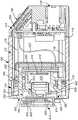
图2是沿着图1中的线2-2剖解的外壳的侧面剖面图;Figure 2 is a side cross-sectional view of the housing taken along line 2-2 in Figure 1;
图3是根据一示例性实施例的图1中的视觉系统的立体图,其中,外壳设置有连接至其上的示例性M12型镜头;3 is a perspective view of the vision system of FIG. 1 with the housing provided with an exemplary M12 type lens attached thereto, according to an exemplary embodiment;
图4是沿着图3中线4-4所剖解的外壳的侧面剖面图;Figure 4 is a side cross-sectional view of the housing taken along line 4-4 in Figure 3;
图5是根据一示例性实施例的图1中的视觉系统的立体图,其中外壳设置有连接至其上的示例性C型底座型镜头;5 is a perspective view of the vision system of FIG. 1 with the housing provided with an exemplary C-mount lens attached thereto, according to an exemplary embodiment;
图6是沿着图5中线6-6剖解的外壳的侧面剖面图;Figure 6 is a side cross-sectional view of the housing taken along line 6-6 in Figure 5;
图7是根据一示例性实施例的图6中所示的外壳设置有连接至其上的示例性C型底座型镜头的视觉系统的立体图,其中镜头被可选的护罩组件覆盖;7 is a perspective view of a vision system with the housing shown in FIG. 6 provided with an exemplary C-mount lens attached thereto, wherein the lens is covered by an optional shield assembly, according to an exemplary embodiment;
图8是根据一示例性实施例的图1中的视觉系统的立体图,其中外壳设置有连接至其上的示例性液体型镜头;8 is a perspective view of the vision system of FIG. 1 with the housing provided with an exemplary liquid-type lens attached thereto, according to an exemplary embodiment;
图9是沿着图8中线9-9剖解的外壳的侧面剖面图;Figure 9 is a side cross-sectional view of the housing taken along line 9-9 in Figure 8;
图10是根据一示例性实施例的图8中的视觉系统的正视图,其中外壳设置有连接至其上的示例性液体型镜头。10 is a front view of the vision system of FIG. 8 with the housing provided with an exemplary liquid-type lens attached thereto, according to an exemplary embodiment.
具体实施方式Detailed ways
根据图1和2,详细示出了包括外部包装或“外壳”100的视觉系统。外壳100可由聚合物、金属、复合物或根据普通技术的不同材料制成。在一实施例中,视觉系统包括前板部分110、主体部分112和后端部分114。使用四个位于前板110的井内且与后端部分的螺纹孔接合的螺栓116,将前板部分(或“前板”)110连接至主体和后端部分,从而抵着垫圈118将三部分压在一起,垫圈可密封外壳防止湿气或其它外界环境介质的渗入。外壳的结构在改变的实施例中有很大的不同。例如,外壳可被构造为具有成为整体的或一体的后端和主体部分或一体的前板和主体。同样地,可以使用其它的固定技术,例如在两部分之间使用夹钳或夹子。1 and 2, a vision system including an outer package or "housing" 100 is shown in detail. The
在此实施例中,螺栓116位于临近近似矩形截面外壳的四个角中的每个角的位置处。每个螺栓116的前端部都包含各自的螺纹井,其可允许使用螺纹固定装置连接附件,或者将外壳本身连接至安装面。可选地,螺栓116可用也通过安装面或附件(没有示出)内的孔的适合的螺栓代替,在合适的压力下将表面/附件共同连接至外壳部分。In this embodiment, the
外壳100的内部支撑着图像传感器212(图2),图像传感器被设置为,作为每个图像像素的阵列,获得每个图像帧。在一个实施例中,传感器阵列是CMOS传感器212(也称为“成像器”),其获得像素数据形式的图像数据。设置玻璃盖210保护传感器阵列212。传感器212安装在印刷电路板250上,如所描绘的,该印刷电路板固定在接近外壳的前端。传感器电路板250还示例性地包括处理电路(如数字信号处理机DSP),其从传感器阵列212接收像素数据并根据非易失性计算机可读程序指令和/或固件指令对数据执行不同的视觉系统处理。传感器电路板250连接各种电源、控制和位于外壳后端114内的电路板220上的其它相关的电路部件。在此实施例中两个板组件220、250示例性地通过多芯电缆连接。其它电路装置和连接是可明显预期的。例如,在另一个实施例中,VSoC装置(前面已描述)可用于执行图像获取和处理。后端部分114(和/或外壳体的其它部分110、112)由铝制成,从而可作为散热器来帮助外壳内的电路产生的热量的散失(下面进一步描述)。The interior of
外部连接器130(或者多个连接器)设置于外壳100的后侧用于提供电源、数据和/或其它接口功能。连接器可操作地连接至电路板220。后端还设有外部状态和控制面板140,用于为用户提供状态显示和视觉系统操作的反馈(例如,指示符号是否被正确地识别和解码)。在外壳100的此位置处或其它合适的位置处还设置有适合的通断开关和其它的接口按钮。An external connector 130 (or connectors) is provided on the rear side of the
传感器212的平面垂直于外壳100的纵向轴线230(也就是相机轴线)。它位于通向前板110中央区域内的光圈150的空间240内。空间240由封闭壁242(具有限定出矩形截面管的相对平坦的侧面)限定,并提供有用于传感器212的间隙。壁242从台阶面244延伸至传感器电路板250的表面。从台阶面244到传感器平面的距离DS大约为6毫米。光圈150由外台阶152和更窄的内台阶154限定。每个台阶如下面所述设置螺纹。特别地,外台阶152限制了大约25.4毫米(1英寸)的直径DOS和大约5毫米的深度LOS(沿着轴向)。同样地,内台阶154限定的直径DIS大约为12mm。外台阶152是每英寸32螺距的内螺纹(TPI),内台阶154的内螺纹螺距是0.5mm。总之,台阶的位置和空间的尺寸被构造和设置为适合于此处使用的每种类型镜头的焦距。The plane of the
在一个实施例中,前板组件110由金属制成(例如模铸铝合金),其使用合适的机加工工艺完成。铸件包括前述的凹口152、154以及其它的用于镜头和其它内部部件的支撑结构(也就是壁242、251、252)。特别地,支撑壁242(等),其接触和/或围绕传感器电路板250,用于帮助从电路板250和它的相关部件排出热量并进入外壳结构内,从外壳结构内热量散失到周围的空气中。在改型的实施例中,支撑结构的布置和构造可以改变。总之,相对于制造前板110使用的材料,在这种支撑结构中使用的壁的厚度选择为可提供足够的结构强度。沿着其前面164,前板组件110包括多个可被内螺纹至任何适合尺寸的螺纹孔160,从而接收相应螺纹的螺钉(下面描述)。可使用这种螺钉将多个配件和附件连接至前板。In one embodiment, the
应注意的是,方向性术语例如“前、后、上、下、顶、底、右、左”,以及它们的变化或同义词,仅应当被认为是相对习惯,不作为结构相对于重力方向的绝对的方向指示。It should be noted that directional terms such as "front, back, up, down, top, bottom, right, left", and their variations or synonyms, should only be considered relative conventions, not as structural relative to the direction of gravity. Absolute directional indication.
特别地根据图1,前板组件110的面164设有一对连接插座170和172,各自朝向光圈150的右方和左方(从前面观察)。两个插座包括各自的连接器,它们与系统的处理器电路(即250和220)连接。右边的插座170用于操作液体镜头的光学件(前面已描述,下面会再次描述)。左边的插座172用于连接和操作通过螺纹孔160直接连接至前板或可被单独安装的照明组件。照明组件在属于同一受让人的,未决美国专利申请中有更详细地描述,序列号[代理人案号119/0116—S/N待提供],名称为具有可变化照明组件的相机系统,由LaurensNunnink发明,与本发明在同一日期提交,并且示教的内容作为有用的背景技术信息在此通过引用明确地并入本文中。1, the
光圈150的周边180设置有环形弹簧组件182,弹簧组件具有一对直径地对立、径向地朝向内的定位肩184。弹簧组件182通过螺接入孔(图5中的502)的相对的螺钉186(在此实施例中为M2螺纹)被可拆卸地固定至正面164。在一个实施例中,螺钉186之间分开的距离(中心距)大约28毫米,通过相机轴线(230)。如下面进一步地描述,可拆卸的弹簧组件被构造和设置为保持液体镜头组件。The
可以预期使用者接受具有用于保护光圈和传感器的端盖(未显示)的外壳100,且使用的镜头是单独购买的,如下面进一步描述的那样,使用者以简单直接的方式连接镜头。可选地,制造者可将镜头设置在外壳上。两种情况下,都有很大的镜头选择范围。The user is expected to accept the
已经根据示例性实施例描述了外壳100和前板组件110的基本结构和功能,现在对与外壳连接的不同类型镜头的使用做进一步地描述。参考图3和4,根据实施例,外壳110设有附加的M12镜头310。作为非限制性的示例,镜头是市场上可买到的具有传统的M12螺纹基座的M12镜头。镜头的外螺纹固定至更窄、更内部的台阶154的内螺纹,并阻止其进一步地向内旋入,通常使用埋头螺母320将其锁定在适当的位置,在连接至前板组件110前埋头螺母首先被螺接到镜头310上。使用的埋头螺母320可由制造者(或其它人员)使用粘结剂或其它固定技术沿着镜头粘贴在适当的位置。这可确保当镜头被紧固至位置(例如由使用者)以与台阶154的正面430形成所示的紧密接合,它还被固定在与传感器的图像平面相距合适、预定的距离处。因而镜头310被锁定在与传感器212的平面相距预定的偏移距离处(以提供合适的焦距)。可选地,使用者设法改变镜头的安装位置时,埋头螺母可不固定至镜头螺纹,并由使用者(或其它人员)反向旋转以固定镜头至期望的位置。Having described the basic structure and function of the
镜头的前端设置有径向朝外的环330,其与可选的、截头圆锥体形状的挡块410(图4)的内周接合。挡块保护镜头前端和外台阶152之间的光圈150的区域,并避免无意地松动或重新调整紧固的镜头/锁紧环310/320,并防止污物和湿气渗入。挡块410可为任何可接受的形状,或者可选地省去。通过与外台阶152内的内螺纹的压入摩擦配合固定至前板组件110。如图4所示,挡块示例性地通过压入螺纹井安装直至其靠着内台阶154的正面430。挡块可由弹性体材料制成。在可替代的实施例中,挡块相对于外壳前板组件110可使用不同的固定系统,例如夹子或接合螺纹。The front end of the lens is provided with a radially outwardly facing
显然连接和分离示例性的M12镜头310相对地简单,并且相对于内台阶154和(可选地)外台阶152仅需螺纹旋转很少的部件。因而,使用者或制造者可由一些现有的部件按意愿组装M12镜头视觉系统。同样地,如果使用者需要基于C型底座镜头的视觉系统,外壳可如图5-7所示组装。It will be apparent that attaching and detaching the
如所示,示例性的C型底座镜头510的外螺纹基座512被螺纹连接至如图6所示的外台阶152的内螺纹。基座512被紧固直至其后肩620与光圈150的周边180接合。周边180与传感器的平面相隔适当的距离以便为镜头510相对于传感器图像平面提供合适的焦距。在周边180上的镜头肩620可以相对于周围的前端面164轻微地凹进(如所示)以提供恰当的间隙,或者其可相对于此处凸起以提供恰当的焦距。在可替代的实施例中,台阶152及其前周面可以为可锁定的插入件,该插入件在周围的前板组件(例如,在插入件和前板之间匹配使用外部同轴的螺纹)内可调节以允许镜头的固定位置发生变化,从而改变焦距。特别地,与前板组件110的几何形状结合的镜头510的光学部件,聚焦接收的光线,从而它们不受镜头510的后端630的影响而通过小直径的台阶154,进入到空间240内。以这种方式,镜头510接收的光线被聚焦以覆盖传感器212的区域。As shown, the externally threaded
C型底座镜头可选地被护罩(或端盖)组件710(图7)覆盖,主要地保护其免于污物/污染物和湿气的进入。护罩710还可保护镜头设置不受到无意地改变。护罩组件包括盖着正面(164)的垫片板720和上覆的护罩基座730。垫片板720和护罩基座设有通孔,该通孔露出每个装配螺栓116的中心螺纹孔(120)。这允许系统可按上面所描述的那样安装或接收护罩基座730上面的附加附件。因而在这种配置下垫片板720和护罩基座730盖住和密封插座(170,172)。在可替代的实施例中,插座170和172或其中之一可以通过垫片板720和护罩基座730露出。护罩基座730和垫片板720被固定在前板组件110上,前板组件110通过四个螺钉(没有示出)受压固定,所述螺钉螺纹接入在前板组件110上形成的螺钉孔160内。在此实施例中,护罩基座730在每个螺纹孔160的区域是埋头的以接收相应形状的机器螺钉。固定护罩基座730和(可选的)垫片板720的不同的螺钉或其它任何固定装置可用于可替代的实施例中。护罩基座730的前环732容纳护罩主体740,其覆盖并盖住镜头510。护罩主体740可被构造为一段,或被构造为多段(例如示出的主体和凸头)。其可通过螺纹连接或其它的固定装置固定至环732。The C-mount lens is optionally covered by a shroud (or end cap) assembly 710 (FIG. 7), primarily protecting it from the ingress of dirt/contamination and moisture.
特别地,参考图8-10,根据示例性实施例,外壳100和前板组件110的通用性使其能够安装自动控制、自动聚焦的液体镜头810。也根据前面的描述,液体镜头使用两种等密度的液体——油是绝缘体而水是导体。通过周围的电路穿过镜头的电压的变化,引起液体-液体界面曲率的变化,这又引起镜头焦距的改变。使用液体镜头的一些显著的优点是镜头的耐用性(其没有机械运动的零件)、其快速的响应时间、其相对较好的光学质量、其低的能量消耗和尺寸大小。使用液体镜头通过消除手工接触镜头的需要来简化安装、设置和维护视觉系统。如上所述,相对其它的自动调焦机构,液体镜头具有极其快的响应时间。其还是从物体到物体(表面到表面)的读取距离变化或从一个物体读取转变到另一个物体的过程的理想应用。In particular, referring to FIGS. 8-10 , the versatility of
在此实施例中,示例性的液体镜头810可基于市场上能够买到的液体镜头部件910(图9),购于法国Varioptic SA。液体镜头部件910安装在外壳层/外壳820内,通过前面所述的弹簧肩184固定在适当的位置。可以明确可为液体镜头使用不同的压持装置。例如,外壳可设置有接合外台阶152的螺纹的C型底座。弹簧保持镜头组件的优点是允许把连接器电缆830定位在恰当地通向插座170的位置(其中电缆的连接器832在图8中显示是连接的)。应注意的是插座和连接器可以是任何可接受的提供足够连接以控制镜头的多针装置。In this embodiment, an exemplary
镜头外壳体或外壳820的内面与一O型环920(或其它的允许中间开孔的弹性结构)接合,该O型环又挤压在电路板922上。电路板922包括根据相应技术用于对镜头部件910进行调焦的控制电路。镜头被挤压在电路板和内部的固定镜头组件940之间,固定镜头组件940将来自液体镜头部件的光线聚焦至传感器212。固定镜头组件940通过接合内台阶154的螺纹固定至前板组件110内。锁紧环942可防止这种镜头组件940的松动。由弹簧定位肩184施加的压力足够使镜头部件910免于运动和振动,但此压力还要保持在避免过度挤压镜头部件910的预设规定内,过度挤压会影响性能或破坏镜头。The inner face of the lens housing or
简要地参考图10的前视图,弹簧保持肩被设置为与相应的位于镜头外壳/外壳体820的每个对立侧的支座1010接合。类似弹簧组件压持螺钉186,支座1010相对于系统外壳100的几何形状(顶、底、左侧和右侧)以不垂直、不水平的角度设置。这允许电缆830从镜头外壳/外壳体的顶端伸出而没有受到压持部件的影响。在此示例中,弹簧肩184(和支座1010)沿着基本垂直于螺钉186之间的线对齐。在可替代的实施例中,更多的或更少的螺钉和/或弹簧肩184(除了其它固定装置)可用于以相对于外壳100的正面164保持镜头810。同样地,可以预期整个弹簧组件可被构造作为单个单元,其具有合适数量的保持肩以固定镜头,或作为一多部件单元,每个都具有一个或多个肩(如所示)。Referring briefly to the front view of FIG. 10 , the spring retaining shoulders are arranged to engage with
可以明确地是,在可替代的实施例中,内部固定镜头组件942和盖上的液体镜头模块801两者(或其中之一)的部件的设置有很大的不同。描述的示例性实施例是一种由制造者或使用者可以简单组装的、有效的设置。It is clear that in alternative embodiments, the arrangement of the components of both (or either) of the internal fixed
很明确的是,此视觉系统外壳和相应的前板结构提供了一种高度通用的系统,用于选择和“直接地连接”不同的需要的镜头和镜头底座类型,传统上在没有附加适配器的单独的外壳上它们是不可互换的。这种适配器会降低精度、增加部件松动的几率且通常会增加系统的复杂性。此处得到的视觉系统需要很少的专用部件,允许制造者和最终使用者对其更多定制。更特别地,系统使最终用户能够改变外镜头类型从而系统可根据需要更新或从一先前的使用重新布置新的使用任务。Clearly, this vision system housing and corresponding front plate structure provide a highly versatile system for selecting and "directly attaching" different required types of lenses and lens mounts, traditionally without additional adapters. They are not interchangeable on individual housings. Such adapters reduce accuracy, increase the chance of loose parts, and generally increase the complexity of the system. The resulting vision system requires few specialized components, allowing for greater customization by manufacturers and end users. More particularly, the system enables the end user to change the outer lens type so that the system can update or rearrange new usage tasks from a previous usage as needed.
前面已经详细描述了本发明的示例性实施例。在没有脱离本发明精神和范围内可以进行不同的改变和添加。上面描述的每个实施例都可以与其他的实施例结合以提供更多的特点。而且,虽然在前面描述了本发明的设备和方法的多个独立实施例,但此处描述的内容仅作为本发明原理的示例性运用。例如,虽然示例性的外壳被配合使用M12和C型底座镜头,可以明确可以使用适配器以允许连接其它类型镜头,例如T型底座镜头,例如前面描述的具有外台阶插入件的可替代的实施例。同样地,前板组件可被构造和设置为通过合适的尺寸和螺纹台阶光圈连接不同的底座。而且,虽然使用螺钉连接不同的部件,可以明确其它类型的固定件可用于不同的连接,例如快速连接器、铆钉、夹子等。而且,在一个实施例中,可制造多个前板组件并将其提供给标准的主体部分和后端以使视觉系统具有更广泛的通用性。另外,其中的任何过程或处理器可以包括一个或多个电子硬件组件、计算机可读介质的非程序指令形式的软件,或硬件和软件的结合。一般地说,应当宽泛地将术语“处理过程(process)”理解为包括不同硬件部件的结合和/或在系统或方法内实施一个或多个功能的软件程序步骤。因此,这些描述仅被作为示例,而不限制本发明的范围。Exemplary embodiments of the present invention have been described in detail above. Various changes and additions may be made without departing from the spirit and scope of the invention. Each of the embodiments described above can be combined with other embodiments to provide further features. Furthermore, while several separate embodiments of the apparatus and method of the present invention have been described in the foregoing, what is described herein is merely illustrative of the application of the principles of the present invention. For example, while the exemplary housing is used with M12 and C-mount lenses, it is clear that adapters can be used to allow the attachment of other types of lenses, such as T-mount lenses, such as the alternative embodiment described earlier with an outer stepped insert . Likewise, the front plate assembly can be constructed and arranged to connect different bases with suitable dimensions and threaded step apertures. Also, although screws are used to connect different components, it is clear that other types of fasteners can be used for different connections, such as quick connectors, rivets, clips, and the like. Also, in one embodiment, multiple front plate assemblies can be fabricated and provided to a standard body portion and back end to allow wider versatility of the vision system. In addition, any process or processor therein may include one or more electronic hardware components, software in the form of computer-readable media other than program instructions, or a combination of hardware and software. In general, the term "process" should be broadly understood to include the combination of different hardware components and/or software program steps that implement one or more functions within a system or method. Accordingly, these descriptions are given by way of example only, and do not limit the scope of the present invention.
Claims (12)
Translated fromChineseApplications Claiming Priority (3)
| Application Number | Priority Date | Filing Date | Title |
|---|---|---|---|
| US13/302,751 | 2011-11-22 | ||
| US13/302,751US8947590B2 (en) | 2011-11-22 | 2011-11-22 | Vision system camera with mount for multiple lens types |
| CN2012104808371ACN103139454A (en) | 2011-11-22 | 2012-11-22 | Vision system camera with mount for multiple lens types |
Related Parent Applications (1)
| Application Number | Title | Priority Date | Filing Date |
|---|---|---|---|
| CN2012104808371ADivisionCN103139454A (en) | 2011-11-22 | 2012-11-22 | Vision system camera with mount for multiple lens types |
Publications (2)
| Publication Number | Publication Date |
|---|---|
| CN115103092Atrue CN115103092A (en) | 2022-09-23 |
| CN115103092B CN115103092B (en) | 2025-06-03 |
Family
ID=48222186
Family Applications (3)
| Application Number | Title | Priority Date | Filing Date |
|---|---|---|---|
| CN201910644705.XAActiveCN110365881B (en) | 2011-11-22 | 2012-11-22 | Vision system camera with mount for multiple lens types |
| CN202210668222.5AActiveCN115103092B (en) | 2011-11-22 | 2012-11-22 | Vision system cameras with mounts for multiple lens types |
| CN2012104808371APendingCN103139454A (en) | 2011-11-22 | 2012-11-22 | Vision system camera with mount for multiple lens types |
Family Applications Before (1)
| Application Number | Title | Priority Date | Filing Date |
|---|---|---|---|
| CN201910644705.XAActiveCN110365881B (en) | 2011-11-22 | 2012-11-22 | Vision system camera with mount for multiple lens types |
Family Applications After (1)
| Application Number | Title | Priority Date | Filing Date |
|---|---|---|---|
| CN2012104808371APendingCN103139454A (en) | 2011-11-22 | 2012-11-22 | Vision system camera with mount for multiple lens types |
Country Status (3)
| Country | Link |
|---|---|
| US (3) | US8947590B2 (en) |
| CN (3) | CN110365881B (en) |
| DE (1) | DE102012111231B4 (en) |
Families Citing this family (24)
| Publication number | Priority date | Publication date | Assignee | Title |
|---|---|---|---|---|
| US8134116B2 (en) | 2009-01-12 | 2012-03-13 | Cognex Corporation | Modular focus system for image based code readers |
| US10498933B2 (en) | 2011-11-22 | 2019-12-03 | Cognex Corporation | Camera system with exchangeable illumination assembly |
| US11366284B2 (en) | 2011-11-22 | 2022-06-21 | Cognex Corporation | Vision system camera with mount for multiple lens types and lens module for the same |
| US8947590B2 (en)* | 2011-11-22 | 2015-02-03 | Cognex Corporation | Vision system camera with mount for multiple lens types |
| JP5983398B2 (en)* | 2012-12-28 | 2016-08-31 | 株式会社Jvcケンウッド | Imaging device |
| JP6459961B2 (en)* | 2013-03-15 | 2019-01-30 | 株式会社ニコン | Receiver |
| US9823552B2 (en) | 2013-12-20 | 2017-11-21 | Back Bone Gear Inc. | Lens and sensor attachment for a digital camera and related retrofit kit and retrofit method |
| US20140132815A1 (en)* | 2014-01-27 | 2014-05-15 | Meizhou XiuYing Enterprise Company Limited | Digital camera structure capable of selectively mounting a camera lens |
| CN105425527B (en)* | 2014-09-03 | 2018-03-20 | 深圳富泰宏精密工业有限公司 | More camera lens camera devices |
| AT519192B1 (en) | 2016-09-19 | 2019-03-15 | B & R Ind Automation Gmbh | Camera for industrial image processing |
| US10133158B2 (en)* | 2016-10-17 | 2018-11-20 | Panasonic Intellectual Property Management Co., Ltd. | Imaging device |
| KR101944412B1 (en)* | 2017-03-23 | 2019-01-31 | 엘지이노텍 주식회사 | Liquid lens, camera module and optical device/instrument including the same |
| JP6648375B2 (en) | 2018-05-21 | 2020-02-14 | エスゼット ディージェイアイ テクノロジー カンパニー リミテッドSz Dji Technology Co.,Ltd | Imaging system and moving object |
| USD894991S1 (en)* | 2018-07-24 | 2020-09-01 | Hanwha Techwin Co., Ltd. | Camera |
| USD896297S1 (en)* | 2018-07-24 | 2020-09-15 | Hanwha Techwin Co., Ltd. | Camera |
| JP6777171B2 (en)* | 2019-01-18 | 2020-10-28 | 株式会社ニコン | Lens barrel and imaging device |
| EP3719569B1 (en)* | 2019-04-01 | 2024-08-14 | Cognex Corporation | Vision system camera with mount for multiple lens types and lens module for the same |
| USD939325S1 (en)* | 2019-10-11 | 2021-12-28 | John F. Bently | Mounting holder |
| DE102019132337B4 (en)* | 2019-11-28 | 2024-05-23 | GeT Components Group BV | Lens adapter |
| DE102020125369A1 (en) | 2020-09-29 | 2022-03-31 | Sick Ag | lens module |
| CN112492171A (en)* | 2020-12-02 | 2021-03-12 | 陕西赛威电气测试有限公司 | Camera assembly for visually identifying sulfur hexafluoride density meter |
| USD1061289S1 (en) | 2023-05-08 | 2025-02-11 | Lsi Industries, Inc. | Infrared sensor lens |
| USD1061288S1 (en) | 2023-05-08 | 2025-02-11 | Lsi Industries, Inc. | Infrared sensor lens |
| USD1096890S1 (en)* | 2023-11-10 | 2025-10-07 | SAM-Dimension GmbH | Camera |
Citations (7)
| Publication number | Priority date | Publication date | Assignee | Title |
|---|---|---|---|---|
| WO1995034988A2 (en)* | 1994-06-14 | 1995-12-21 | Telepresence Systems Limited | Miniature cameras |
| CN1214459A (en)* | 1997-09-10 | 1999-04-21 | 柯尼卡株式会社 | Camera equipped with zoom lens |
| US20020130963A1 (en)* | 2001-03-15 | 2002-09-19 | Panavision, Inc. | Lens mount apparatus for a high definition video camera |
| CN2672677Y (en)* | 2003-12-20 | 2005-01-19 | 鸿富锦精密工业(深圳)有限公司 | Lens module |
| US20060034596A1 (en)* | 2004-08-13 | 2006-02-16 | Pentax Corporation | Assembly-stage focus adjustment mechanism of a zoom lens |
| WO2007053404A2 (en)* | 2005-10-28 | 2007-05-10 | Donnelly Corporation | Camera module for vehicle vision system |
| US20100097519A1 (en)* | 2008-10-16 | 2010-04-22 | Byrne Steven V | Compact Camera and Cable System for Vehicular Applications |
Family Cites Families (234)
| Publication number | Priority date | Publication date | Assignee | Title |
|---|---|---|---|---|
| US1873149A (en) | 1930-04-19 | 1932-08-23 | Perez Fernando | Microscope for examining pictures with rasant lateral lighting |
| US2409328A (en) | 1944-10-26 | 1946-10-15 | Raymond S Wilder | Illuminating unit for optical projectors |
| FR2044541A5 (en) | 1969-05-23 | 1971-02-19 | Eclair Int | |
| US3709132A (en)* | 1970-11-27 | 1973-01-09 | Polaroid Corp | Photographic focus adjustment apparatus |
| US3940777A (en) | 1973-08-27 | 1976-02-24 | Canon Kabushiki Kaisha | Casing of a mechanical mounting for the interchangeable lenses and a camera system using the same |
| US4072396A (en) | 1975-07-10 | 1978-02-07 | W. R. Weaver | Focussing objective mechanism for telescopic rifle sights |
| US4230403A (en) | 1977-02-08 | 1980-10-28 | Canon Kabushiki Kaisha | Mounting for interchangeable camera lens assembly with diaphragm means |
| US4160590A (en) | 1978-04-17 | 1979-07-10 | Polaroid Corporation | Removable (lens position limiting) stop for auto-manual focusing cameras |
| US4451131A (en) | 1979-02-23 | 1984-05-29 | Canon Kabushiki Kaisha | Interchangeable camera lens assembly |
| JPS5647522U (en) | 1979-09-17 | 1981-04-27 | ||
| JPS579912U (en) | 1980-06-18 | 1982-01-19 | ||
| US4494828A (en) | 1981-04-09 | 1985-01-22 | Minolta Camera Kabushiki Kaisha | Zoom lens system of relatively high zoom ratio ranging to wide angle photography |
| JPS58138908U (en) | 1982-03-12 | 1983-09-19 | キノ精密工業株式会社 | Focus lock device in lens barrel |
| JPH0670682B2 (en) | 1983-08-19 | 1994-09-07 | 日照技研株式会社 | Lighting equipment |
| JPS6053912A (en) | 1983-09-02 | 1985-03-28 | Minolta Camera Co Ltd | Mount device for attaching and detaching lens of camera and interchangeable lens |
| US4591253A (en) | 1983-10-06 | 1986-05-27 | Robotic Vision Systems, Inc. | Adaptive vision system |
| US5668364A (en) | 1985-02-28 | 1997-09-16 | Symbol Technologies, Inc. | Target finder in electro-optical scanners |
| US5149950A (en) | 1985-02-28 | 1992-09-22 | Symbol Technologies, Inc. | Hand-held laser scanning head having detachable handle portion |
| US4871238A (en) | 1986-03-06 | 1989-10-03 | Canon Kabushiki Kaisha | Photographic optical device with variable magnification |
| US5308966A (en) | 1986-08-08 | 1994-05-03 | Norand Corporation | Hand-held instant bar code reader having automatic focus control for operation over a range of distances |
| US5969321A (en) | 1986-08-08 | 1999-10-19 | Norand Corporation | Hand-held optically readable information set reader with operation over a range of distances |
| US5640001A (en) | 1986-08-08 | 1997-06-17 | Norand Technology Corporation | Hand-held instant bar code reader having automatic focus control for operation over a range of distances |
| US5313053A (en) | 1990-01-18 | 1994-05-17 | Norand Corporation | Laser scanner module having integral interfacing with hand-held data capture terminal |
| US4877949A (en) | 1986-08-08 | 1989-10-31 | Norand Corporation | Hand-held instant bar code reader system with automated focus based on distance measurements |
| US4781448A (en) | 1987-03-02 | 1988-11-01 | Medical Concepts Inc. | Zoom lens adapter for endoscopic camera |
| FR2625010B1 (en) | 1987-12-18 | 1990-04-27 | Sodern | HIGH POWER ILLUMINATOR FOR CAMERA |
| US5019699A (en) | 1988-08-31 | 1991-05-28 | Norand Corporation | Hand-held optical character reader with means for instantaneously reading information from a predetermined area at an optical sensing area |
| KR920006031B1 (en) | 1988-05-09 | 1992-07-27 | 다떼이시 덴끼 가부시끼 가이샤 | Inspection equipment such as substrate and its operation method |
| US5136320A (en) | 1988-06-30 | 1992-08-04 | Asahi Kogaku Kogyo Kabushiki Kaisha | Electronically controlled camera having macro and normal operational modes |
| US5291232A (en) | 1988-06-30 | 1994-03-01 | Asahi Kogaku Kogyo Kabushiki Kaisha | Device for controlling an operation of a movable member |
| US6974085B1 (en) | 1988-08-31 | 2005-12-13 | Intermec Ip Corp. | System for reading optical indicia |
| US6681994B1 (en) | 1988-08-31 | 2004-01-27 | Intermec Ip Corp. | Method and apparatus for optically reading information |
| US5478997A (en) | 1988-10-21 | 1995-12-26 | Symbol Technologies, Inc. | Symbol scanning system and method having adaptive pattern generation |
| US5010412A (en) | 1988-12-27 | 1991-04-23 | The Boeing Company | High frequency, low power light source for video camera |
| US5304786A (en) | 1990-01-05 | 1994-04-19 | Symbol Technologies, Inc. | High density two-dimensional bar code symbol |
| US5155343A (en) | 1990-03-28 | 1992-10-13 | Chandler Donald G | Omnidirectional bar code reader with method and apparatus for detecting and scanning a bar code symbol |
| US5808285A (en) | 1990-09-17 | 1998-09-15 | Metrologic Instruments, Inc. | Portable code symbol reading device with one-way wireless data packet transmission link to base unit employing condition-dependent acoustical signalling for data packet reception acknowledgement |
| CA2056272C (en) | 1991-06-14 | 2001-10-16 | Patrick Salatto, Jr. | Combined range laser scanner |
| EP0547227A4 (en) | 1991-07-05 | 1994-08-10 | Kobe Steel Ltd | Optical surface inspection device for mill roll |
| US5378883A (en) | 1991-07-19 | 1995-01-03 | Omniplanar Inc. | Omnidirectional wide range hand held bar code reader |
| US5811828A (en) | 1991-09-17 | 1998-09-22 | Norand Corporation | Portable reader system having an adjustable optical focusing means for reading optical information over a substantial range of distances |
| US5864128A (en) | 1991-10-15 | 1999-01-26 | Geo Labs, Inc. | Lens with variable focal length |
| US5189463A (en) | 1992-02-12 | 1993-02-23 | David G. Capper | Camera aiming mechanism and method |
| US6347163B2 (en) | 1994-10-26 | 2002-02-12 | Symbol Technologies, Inc. | System for reading two-dimensional images using ambient and/or projected light |
| US5786582A (en) | 1992-02-27 | 1998-07-28 | Symbol Technologies, Inc. | Optical scanner for reading and decoding one- and two-dimensional symbologies at variable depths of field |
| US5756981A (en) | 1992-02-27 | 1998-05-26 | Symbol Technologies, Inc. | Optical scanner for reading and decoding one- and-two-dimensional symbologies at variable depths of field including memory efficient high speed image processing means and high accuracy image analysis means |
| US5349172A (en) | 1992-02-27 | 1994-09-20 | Alex Roustaei | Optical scanning head |
| US5331176A (en) | 1992-04-10 | 1994-07-19 | Veritec Inc. | Hand held two dimensional symbol reader with a symbol illumination window |
| US5245172A (en) | 1992-05-12 | 1993-09-14 | United Parcel Service Of America, Inc. | Voice coil focusing system having an image receptor mounted on a pivotally-rotatable frame |
| US5326963A (en) | 1992-10-02 | 1994-07-05 | Kronos Incorporated | Electro-optic barcode reader |
| US6935566B1 (en) | 1997-02-03 | 2005-08-30 | Symbol Technologies, Inc. | Portable instrument for electro-optically reading indicia and for projecting a bit-mapped image |
| JP3253168B2 (en) | 1993-04-01 | 2002-02-04 | キヤノン株式会社 | Lens barrel |
| US5591955A (en) | 1993-05-11 | 1997-01-07 | Laser; Vadim | Portable data file readers |
| US5365597A (en) | 1993-06-11 | 1994-11-15 | United Parcel Service Of America, Inc. | Method and apparatus for passive autoranging using relaxation |
| US6019287A (en) | 1993-10-06 | 2000-02-01 | 3M Innovative Properties Company | Security reader for automatic detection of tampering and alteration |
| US6114712A (en) | 1996-10-09 | 2000-09-05 | Symbol Technologies, Inc. | One piece optical assembly for low cost optical scanner |
| JPH07234501A (en) | 1994-02-22 | 1995-09-05 | Matsushita Electric Ind Co Ltd | Color separation device and color image reading device |
| US5825006A (en) | 1994-03-04 | 1998-10-20 | Welch Allyn, Inc. | Optical reader having improved autodiscrimination features |
| US7387253B1 (en) | 1996-09-03 | 2008-06-17 | Hand Held Products, Inc. | Optical reader system comprising local host processor and optical reader |
| US5504367A (en) | 1994-03-21 | 1996-04-02 | Intermec Corporation | Symbology reader illumination system |
| US5550364A (en) | 1994-03-21 | 1996-08-27 | Intermec Corporation | Method and apparatus for spotter beam formation using a partitioned optical element |
| US5598007A (en) | 1994-03-21 | 1997-01-28 | Intermec Corporation | Symbology reader with fixed focus spotter beam |
| US5513264A (en) | 1994-04-05 | 1996-04-30 | Metanetics Corporation | Visually interactive encoding and decoding of dataforms |
| US5672858A (en) | 1994-06-30 | 1997-09-30 | Symbol Technologies Inc. | Apparatus and method for reading indicia using charge coupled device and scanning laser beam technology |
| US5580163A (en) | 1994-07-20 | 1996-12-03 | August Technology Corporation | Focusing light source with flexible mount for multiple light-emitting elements |
| US5572006A (en) | 1994-07-26 | 1996-11-05 | Metanetics Corporation | Automatic exposure single frame imaging systems |
| US6073846A (en) | 1994-08-17 | 2000-06-13 | Metrologic Instruments, Inc. | Holographic laser scanning system and process and apparatus and method |
| US5500516A (en) | 1994-08-30 | 1996-03-19 | Norand Corporation | Portable oblique optical reader system and method |
| US5473150A (en) | 1994-09-26 | 1995-12-05 | Allen-Bradley Company, Inc. | Bar code reader with closed-loop scan beam focusing |
| JPH08122884A (en) | 1994-10-20 | 1996-05-17 | Fuji Photo Optical Co Ltd | Mount device for television camera |
| DK0788634T3 (en) | 1994-10-25 | 2000-12-04 | United Parcel Service Inc | Automatic electronic camera for capturing images of labels |
| DE69502293T2 (en) | 1994-10-25 | 1998-11-26 | United Parcel Service Of America, Inc., Atlanta, Ga. | METHOD AND DEVICE FOR A PORTABLE CONTACTLESS IMAGE RECORDING DEVICE |
| US5814803A (en) | 1994-12-23 | 1998-09-29 | Spectra-Physics Scanning Systems, Inc. | Image reader with multi-focus lens |
| US5786586A (en) | 1995-01-17 | 1998-07-28 | Welch Allyn, Inc. | Hand-held optical reader having a detachable lens-guide assembly |
| US5569902A (en) | 1995-01-17 | 1996-10-29 | Welch Allyn, Inc. | Contact two-dimensional bar code reader having pressure actuated switch |
| JPH0991368A (en) | 1995-07-20 | 1997-04-04 | Fujitsu Ltd | Optical reader |
| US6060722A (en) | 1995-05-15 | 2000-05-09 | Havens; William H. | Optical reader having illumination assembly including improved aiming pattern generator |
| DE69637397T2 (en) | 1995-05-31 | 2009-01-02 | Symbol Technologies, Inc. | Optical barcode scanner |
| US5587843A (en) | 1995-06-06 | 1996-12-24 | Industrial Technology Research Institute | Zoom lens mechanism |
| US5783811A (en) | 1995-06-26 | 1998-07-21 | Metanetics Corporation | Portable data collection device with LED targeting and illumination assembly |
| CN1244014C (en)* | 1995-10-13 | 2006-03-01 | 株式会社尼康 | Camera system and intermediate adapter |
| JPH09128471A (en) | 1995-11-02 | 1997-05-16 | Tec Corp | Code reader |
| US5878395A (en) | 1995-12-08 | 1999-03-02 | Intermec Ip Corp. | Code reading terminal with integrated vehicular head-up display capability |
| US5793033A (en) | 1996-03-29 | 1998-08-11 | Metanetics Corporation | Portable data collection device with viewing assembly |
| US5773810A (en) | 1996-03-29 | 1998-06-30 | Welch Allyn, Inc. | Method for generating real time degree of focus signal for handheld imaging device |
| WO1998016896A1 (en) | 1996-10-16 | 1998-04-23 | Omniplanar, Inc. | Hand-held bar code reader with laser scanning and 2d image capture |
| JP3129245B2 (en) | 1996-10-31 | 2001-01-29 | オムロン株式会社 | Imaging device |
| JP3811235B2 (en) | 1996-11-05 | 2006-08-16 | オリンパス株式会社 | Bar code reader |
| US6179208B1 (en) | 1997-01-31 | 2001-01-30 | Metanetics Corporation | Portable data collection device with variable focusing module for optic assembly |
| US6845915B2 (en) | 1997-02-03 | 2005-01-25 | Symbol Technologies, Inc. | Extended range bar code reader |
| US6223986B1 (en) | 1997-04-17 | 2001-05-01 | Psc Scanning, Inc. | Aiming aid for optical data reading |
| US5825559A (en) | 1997-06-27 | 1998-10-20 | Eastman Kodak Company | Optical assembly having a dual purpose focus |
| US6022124A (en) | 1997-08-19 | 2000-02-08 | Ppt Vision, Inc. | Machine-vision ring-reflector illumination system and method |
| JPH1164713A (en) | 1997-08-26 | 1999-03-05 | Yamano Kogaku:Kk | Detachable lens block and video camera system using the same |
| JP3471201B2 (en) | 1997-09-05 | 2003-12-02 | 株式会社東芝 | Imaging module and imaging device |
| US6561428B2 (en) | 1997-10-17 | 2003-05-13 | Hand Held Products, Inc. | Imaging device having indicia-controlled image parsing mode |
| US6298176B2 (en) | 1997-10-17 | 2001-10-02 | Welch Allyn Data Collection, Inc. | Symbol-controlled image data reading system |
| US5897195A (en) | 1997-12-09 | 1999-04-27 | Optical Gaging, Products, Inc. | Oblique led illuminator device |
| US6481857B2 (en) | 1997-12-16 | 2002-11-19 | Reflexite Corporation | Perforated retroreflective film |
| US6669093B1 (en) | 1997-12-19 | 2003-12-30 | Telxon Corporation | Hand-held dataform reader having multiple target area illumination sources for independent reading of superimposed dataforms |
| JP3668383B2 (en) | 1998-02-27 | 2005-07-06 | 松下電器産業株式会社 | Electronic component mounting equipment |
| US6186400B1 (en) | 1998-03-20 | 2001-02-13 | Symbol Technologies, Inc. | Bar code reader with an integrated scanning component module mountable on printed circuit board |
| EP0945934B1 (en) | 1998-03-26 | 2008-03-12 | Matsushita Electric Works, Ltd. | Electrical coupler for detachable interconnection between a main unit and an external unit |
| EP0957448A3 (en) | 1998-05-15 | 2001-09-26 | PSC Scanning, Inc. | Optical code reader mouse |
| US6340114B1 (en) | 1998-06-12 | 2002-01-22 | Symbol Technologies, Inc. | Imaging engine and method for code readers |
| US6659350B2 (en) | 2000-11-01 | 2003-12-09 | Hand Held Products | Adjustable illumination system for a barcode scanner |
| US20030019934A1 (en) | 1998-07-08 | 2003-01-30 | Hand Held Products, Inc. | Optical reader aiming assembly comprising aperture |
| US6164544A (en) | 1998-07-08 | 2000-12-26 | Welch Allyn Data Collection, Inc. | Adjustable illumination system for a barcode scanner |
| US6066857A (en) | 1998-09-11 | 2000-05-23 | Robotic Vision Systems, Inc. | Variable focus optical system |
| US6098887A (en) | 1998-09-11 | 2000-08-08 | Robotic Vision Systems, Inc. | Optical focusing device and method |
| US6273338B1 (en) | 1998-09-22 | 2001-08-14 | Timothy White | Low cost color-programmable focusing ring light |
| JP3839975B2 (en) | 1998-10-09 | 2006-11-01 | キヤノン株式会社 | Code reader |
| DE69803459T2 (en) | 1998-10-30 | 2003-02-13 | Datalogic S.P.A., Lippo Di Calderara Di Reno | Optical device and method for sighting and visually displaying a readout area |
| US7097105B2 (en) | 1998-12-03 | 2006-08-29 | Metrologic Instruments, Inc. | Automatically-activated hand-supportable omni-directional laser scanning bar code symbol reader having a user-selectable linear scanning menu-reading mode supported by a stroboscopically-pulsed omni-directional laser scanning pattern for improved bar code symbol navigation and alignment during menu-reading operations |
| US6449430B1 (en) | 1999-01-11 | 2002-09-10 | Fuji Photo Film Co., Ltd. | Lens-fitted photo film unit and assembling method for the same |
| US6651888B1 (en) | 1999-02-02 | 2003-11-25 | Symbol Technologies, Inc. | Beam shaping system and diverging laser beam for scanning optical code |
| US6266175B1 (en) | 1999-04-27 | 2001-07-24 | Psc Scanning, Inc. | Scanner with synchronously switched optics |
| US6385507B1 (en) | 1999-06-24 | 2002-05-07 | U.S. Philips Corporation | Illumination module |
| US6781630B2 (en) | 1999-07-26 | 2004-08-24 | Takashi Yoshimine | Adapter system and image pick-up system |
| US7270274B2 (en) | 1999-10-04 | 2007-09-18 | Hand Held Products, Inc. | Imaging module comprising support post for optical reader |
| US6832725B2 (en) | 1999-10-04 | 2004-12-21 | Hand Held Products, Inc. | Optical reader comprising multiple color illumination |
| US6266196B1 (en) | 1999-11-19 | 2001-07-24 | New Focus, Inc. | Multi-position optic mount |
| US6339680B1 (en) | 2000-01-10 | 2002-01-15 | Jaquelynne Mauvais | Selectable multi-lens disposable camera |
| ES2322988T3 (en) | 2000-02-23 | 2009-07-03 | Datalogic S.P.A. | APPARATUS AND PROCEDURE FOR READING AND DECODING OPTICAL CODES WITH INDICATION OF THE RESULT. |
| US20040238637A1 (en) | 2000-04-18 | 2004-12-02 | Metrologic Instruments, Inc. | Point of sale (POS) based bar code reading and cash register systems with integrated internet-enabled customer-kiosk terminals |
| US20030132291A1 (en) | 2002-01-11 | 2003-07-17 | Metrologic Instruments, Inc. | Point of sale (POS) station having bar code reading system with integrated internet-enabled customer-kiosk terminal |
| US20030205620A1 (en) | 2002-05-03 | 2003-11-06 | Sung Byun | Point of sale (POS) based bar code reading systems having light-pipe based bar code read indication subsystems integrated therein |
| US6318924B1 (en)* | 2000-04-20 | 2001-11-20 | Anthony Paul Schiavo, Jr. | Quick-connect for mounting objects |
| WO2001091045A1 (en) | 2000-05-19 | 2001-11-29 | Technology Innovations, Llc | Document with embedded information |
| US6827270B2 (en) | 2000-06-02 | 2004-12-07 | Tohoku Ricoh Co., Ltd | Bar code reader having a rotatory optical deflector and a rotation position detector |
| US6689998B1 (en) | 2000-07-05 | 2004-02-10 | Psc Scanning, Inc. | Apparatus for optical distancing autofocus and imaging and method of using the same |
| ATE423356T1 (en) | 2000-07-11 | 2009-03-15 | Datalogic Spa | DEVICE AND OPTICAL ELEMENT FOR AIMING AND VISUALLY DISPLAYING A READING AREA OF A CODE READER |
| US20020047047A1 (en) | 2000-09-06 | 2002-04-25 | Paul Poloniewicz | Zero-footprint camera-based point-of-sale bar code presentation scanning system |
| US20020039099A1 (en) | 2000-09-30 | 2002-04-04 | Hand Held Products, Inc. | Method and apparatus for simultaneous image capture and image display in an imaging device |
| US7128266B2 (en) | 2003-11-13 | 2006-10-31 | Metrologic Instruments. Inc. | Hand-supportable digital imaging-based bar code symbol reader supporting narrow-area and wide-area modes of illumination and image capture |
| US6832729B1 (en) | 2001-03-23 | 2004-12-21 | Zih Corp. | Portable data collection device for reading fluorescent indicia |
| JP2002287025A (en) | 2001-03-26 | 2002-10-03 | Fuji Photo Optical Co Ltd | Mount changing adapter lens |
| US6651886B2 (en) | 2001-04-13 | 2003-11-25 | Symbol Technologies, Inc. | Optical code readers with holographic optical elements |
| DE10121439A1 (en) | 2001-04-27 | 2002-10-31 | Hensoldt & Soehne Optik | detent mechanism |
| US7111787B2 (en) | 2001-05-15 | 2006-09-26 | Hand Held Products, Inc. | Multimode image capturing and decoding optical reader |
| DE10126087A1 (en) | 2001-05-29 | 2002-12-05 | Sick Ag | Distance determination method and device |
| US6624954B2 (en) | 2001-06-15 | 2003-09-23 | Logitech Europe S.A. | Lens mounting apparatus |
| WO2003036553A1 (en) | 2001-10-19 | 2003-05-01 | Symbol Technologies, Inc. | Electro-optical assembly for image projection, especially in portable instruments |
| US6805295B2 (en) | 2001-11-06 | 2004-10-19 | Symbol Technologies, Ltd. | High speed laser scan module with folded beam path |
| US6636298B1 (en) | 2001-12-18 | 2003-10-21 | Cognex Technology And Investment Corporation | Method and apparatus for focusing an optical inspection system |
| EP1474775A4 (en) | 2002-01-16 | 2007-11-21 | Metrologic Instr Inc | Point of sale (pos) based bar code reading and cash register systems with integrated internet-enabled customer-kiosk terminals |
| US7311260B2 (en) | 2002-01-18 | 2007-12-25 | Microscan Systems Incorporated | Camera positioning and confirmation feedback system |
| US7055747B2 (en) | 2002-06-11 | 2006-06-06 | Hand Held Products, Inc. | Long range optical reader |
| US7073711B2 (en) | 2002-04-19 | 2006-07-11 | Cross Match Technologies, Inc. | Mobile handheld code reader and print scanner system and method |
| US6837433B2 (en) | 2002-04-30 | 2005-01-04 | Hewlett-Packard Development Company, L.P. | Variable focal length imaging device |
| US7073158B2 (en) | 2002-05-17 | 2006-07-04 | Pixel Velocity, Inc. | Automated system for designing and developing field programmable gate arrays |
| US7219843B2 (en) | 2002-06-04 | 2007-05-22 | Hand Held Products, Inc. | Optical reader having a plurality of imaging modules |
| US6663260B1 (en) | 2002-07-23 | 2003-12-16 | Dwayne A. Tieszen | Equipment work light ring |
| US6712270B2 (en) | 2002-08-15 | 2004-03-30 | Symbol Technologies, Inc. | Positioning of photodetectors in optical scanning modules for use in bar code readers for reducing specular reflection |
| US6866198B2 (en) | 2002-10-15 | 2005-03-15 | Symbol Technologies, Inc. | Imaging bar code reader with moving beam simulation |
| US6913471B2 (en) | 2002-11-12 | 2005-07-05 | Gateway Inc. | Offset stackable pass-through signal connector |
| US6918538B2 (en) | 2002-12-18 | 2005-07-19 | Symbol Technologies, Inc. | Image scanning device having a system for determining distance to a target |
| US7025271B2 (en) | 2002-12-18 | 2006-04-11 | Symbol Technologies, Inc. | Imaging optical code reader having selectable depths of field |
| US7066388B2 (en) | 2002-12-18 | 2006-06-27 | Symbol Technologies, Inc. | System and method for verifying RFID reads |
| US7025272B2 (en) | 2002-12-18 | 2006-04-11 | Symbol Technologies, Inc. | System and method for auto focusing an optical code reader |
| US7073715B2 (en) | 2003-02-13 | 2006-07-11 | Symbol Technologies, Inc. | Interface for interfacing an imaging engine to an optical code reader |
| US7097101B2 (en) | 2003-02-13 | 2006-08-29 | Symbol Technologies, Inc. | Interface for interfacing an imaging engine to an optical code reader |
| US7063256B2 (en) | 2003-03-04 | 2006-06-20 | United Parcel Service Of America | Item tracking and processing systems and methods |
| US20070241195A1 (en) | 2006-04-18 | 2007-10-18 | Hand Held Products, Inc. | Optical reading device with programmable LED control |
| EP1626301B1 (en) | 2003-05-15 | 2011-03-30 | Konica Minolta Opto, Inc. | Optical system and imaging device |
| US7007843B2 (en) | 2003-06-09 | 2006-03-07 | Symbol Technologies, Inc. | Light beam shaping arrangement and method in electro-optical readers |
| US6959867B2 (en) | 2003-06-30 | 2005-11-01 | Ryzex, Inc. | Apparatus for aiming a scanner |
| US7222793B2 (en) | 2003-07-09 | 2007-05-29 | Symbol Technologies, Inc. | Arrangement and method of imaging one-dimensional and two-dimensional optical codes at a plurality of focal planes |
| US20060027659A1 (en) | 2003-08-01 | 2006-02-09 | Symbol Technologies, Inc. | Integrated exit window and imaging engine |
| US7478754B2 (en) | 2003-08-25 | 2009-01-20 | Symbol Technologies, Inc. | Axial chromatic aberration auto-focusing system and method |
| JP3842257B2 (en) | 2003-08-28 | 2006-11-08 | Tdk株式会社 | Lighting device |
| CN1802600B (en)* | 2003-10-14 | 2011-05-11 | 日本电产科宝株式会社 | Portable information terminal with camera |
| JP4586026B2 (en) | 2003-11-13 | 2010-11-24 | メトロロジック インスツルメンツ インコーポレイテッド | Hand-supportable imaging-based barcode symbol reader that supports narrow and wide modes of illumination and image capture |
| US7841533B2 (en) | 2003-11-13 | 2010-11-30 | Metrologic Instruments, Inc. | Method of capturing and processing digital images of an object within the field of view (FOV) of a hand-supportable digitial image capture and processing system |
| US7292281B2 (en) | 2003-12-30 | 2007-11-06 | Yi Jen Cheng | Monitoring camera with a far infrared capability |
| EP1707928A4 (en) | 2004-01-23 | 2011-03-09 | Olympus Corp | Image processing system and camera |
| EP1714231B1 (en) | 2004-01-23 | 2011-09-07 | Intermec IP Corporation | Autofocus barcode scanner and the like employing micro-fluidic lens |
| US20050180037A1 (en) | 2004-02-18 | 2005-08-18 | Boulder Nonlinear Systems, Inc. | Electronic filter wheel |
| US7264162B2 (en) | 2004-03-11 | 2007-09-04 | Symbol Technologies, Inc. | Optical adjustment of working range and beam spot size in electro-optical readers |
| US7201318B2 (en) | 2004-03-11 | 2007-04-10 | Symbol Technologies, Inc. | Optical adjustment for increased working range and performance in electro-optical readers |
| JP2005274925A (en) | 2004-03-24 | 2005-10-06 | Pioneer Electronic Corp | Focusing method and focusing device |
| CN100354681C (en)* | 2004-06-03 | 2007-12-12 | 精碟科技股份有限公司 | Capture lens |
| US7182260B2 (en) | 2004-06-29 | 2007-02-27 | Symbol Technologies, Inc. | Aiming light pattern generator in imaging readers for electro-optically reading indicia |
| KR100677332B1 (en) | 2004-07-06 | 2007-02-02 | 엘지전자 주식회사 | Low light quality improvement device and method of mobile terminal |
| US7201321B2 (en) | 2004-08-27 | 2007-04-10 | Symbol Technologies, Inc. | Electro-optically reading direct part markings on workpieces by image capture |
| US7478753B2 (en) | 2004-08-31 | 2009-01-20 | Symbol Technologies, Inc. | System and method for aiming an optical code scanning device |
| US7307663B2 (en) | 2004-09-16 | 2007-12-11 | Pelco | Video surveillance camera |
| US20060060653A1 (en) | 2004-09-23 | 2006-03-23 | Carl Wittenberg | Scanner system and method for simultaneously acquiring data images from multiple object planes |
| ES2368839T3 (en) | 2004-09-24 | 2011-11-22 | Koninklijke Philips Electronics N.V. | LIGHTING SYSTEM. |
| US7721966B2 (en) | 2004-10-18 | 2010-05-25 | Datalogic Scanning, Inc. | System and method of optical reading employing virtual scan lines |
| US7417803B2 (en) | 2004-11-18 | 2008-08-26 | Cognex Technology And Investment Corporation | Focusing mechanism for a vision detector |
| US7315241B1 (en) | 2004-12-01 | 2008-01-01 | Hrl Laboratories, Llc | Enhanced perception lighting |
| US7224540B2 (en) | 2005-01-31 | 2007-05-29 | Datalogic Scanning, Inc. | Extended depth of field imaging system using chromatic aberration |
| US7344273B2 (en) | 2005-03-22 | 2008-03-18 | Binary Works, Inc. | Ring light with user manipulable control |
| US20060213994A1 (en) | 2005-03-22 | 2006-09-28 | Faiz Tariq N | Barcode reading apparatus and method therefor |
| US7392951B2 (en) | 2005-05-17 | 2008-07-01 | Intermec Ip Corp. | Methods, apparatuses and articles for automatic data collection devices, for example barcode readers, in cluttered environments |
| TWI275897B (en) | 2005-06-13 | 2007-03-11 | Coretronic Corp | Illumination system of projector |
| US7559473B2 (en) | 2005-09-15 | 2009-07-14 | Symbol Technologies Inc. | Sensor for activating an aiming pattern of a handheld scanner |
| US7515981B2 (en) | 2005-10-07 | 2009-04-07 | Ops Solutions Llc | Light guided assembly system |
| US7454841B2 (en) | 2005-11-01 | 2008-11-25 | Hunter Engineering Company | Method and apparatus for wheel alignment system target projection and illumination |
| US7621653B2 (en) | 2005-11-22 | 2009-11-24 | Xenopus Electronix, Llc | Multi-function illumination device |
| US20070131770A1 (en) | 2005-12-13 | 2007-06-14 | Laurens Nunnink | Selectable focus direct part mark reader |
| US20070164115A1 (en) | 2006-01-17 | 2007-07-19 | Symboltechnologies, Inc. | Automatic exposure system for imaging-based bar code reader |
| US8181878B2 (en) | 2006-01-25 | 2012-05-22 | Cognex Technology And Investment Corporation | Method and apparatus for providing a focus indication for optical imaging of visual codes |
| US7821569B2 (en) | 2006-02-10 | 2010-10-26 | Lumos Technology Co., Ltd. | Converter lens attachment with built-in light source for compact digital camera |
| JP4566930B2 (en) | 2006-03-03 | 2010-10-20 | 富士通株式会社 | Imaging device |
| US20070247422A1 (en) | 2006-03-30 | 2007-10-25 | Xuuk, Inc. | Interaction techniques for flexible displays |
| US7957007B2 (en) | 2006-05-17 | 2011-06-07 | Mitsubishi Electric Research Laboratories, Inc. | Apparatus and method for illuminating a scene with multiplexed illumination for motion capture |
| US7549582B1 (en) | 2006-05-30 | 2009-06-23 | Cognex Technology And Investment Corporation | Method and apparatus for adjusting focus in a symbology reader |
| GB0615956D0 (en) | 2006-08-11 | 2006-09-20 | Univ Heriot Watt | Optical imaging of physical objects |
| US8233040B2 (en) | 2006-12-01 | 2012-07-31 | Accu-Sort Systems, Inc. | Modular camera and camera system |
| US7813047B2 (en) | 2006-12-15 | 2010-10-12 | Hand Held Products, Inc. | Apparatus and method comprising deformable lens element |
| CN101632030B (en) | 2006-12-15 | 2012-01-11 | 手持产品公司 | Apparatus and methods including deformable lens elements |
| US8033670B2 (en)* | 2006-12-29 | 2011-10-11 | Cognex Corporation | Manually adjustable ruggedized focus mechanism |
| JP5133568B2 (en) | 2007-01-11 | 2013-01-30 | 株式会社ディスコ | Laser processing equipment |
| JP2008262027A (en) | 2007-04-12 | 2008-10-30 | Sony Corp | Multi-lens mounting structure, camera module, and electronic device |
| US20080277480A1 (en) | 2007-05-10 | 2008-11-13 | Serge Thuries | Temperature compensated auto focus control for a microfluidic lens, such as auto focus control for a microfluidic lens of a bar code scanner |
| US7942329B2 (en) | 2007-08-14 | 2011-05-17 | Jadak, Llc | Method for providing user feedback in an autoidentification system |
| US7686223B2 (en) | 2007-08-31 | 2010-03-30 | Symbol Technologies, Inc. | Selectable aiming pattern for an imaging-based bar code reader |
| TWM332873U (en) | 2007-10-30 | 2008-05-21 | Lumos Technology Co Ltd | Additional lens fixing structure of camera |
| US9451142B2 (en) | 2007-11-30 | 2016-09-20 | Cognex Corporation | Vision sensors, systems, and methods |
| US8308069B2 (en) | 2007-12-21 | 2012-11-13 | Hand Held Products, Inc. | User configurable search methods for an area imaging indicia reader |
| US8302864B2 (en) | 2007-12-28 | 2012-11-06 | Cognex Corporation | Method and apparatus using aiming pattern for machine vision training |
| WO2009121775A2 (en) | 2008-04-01 | 2009-10-08 | Bauhaus-Universität Weimar | Method and illumination device for optical contrast enhancement |
| WO2010036403A2 (en) | 2008-05-06 | 2010-04-01 | Flashscan3D, Llc | System and method for structured light illumination with frame subwindows |
| WO2009141939A1 (en) | 2008-05-19 | 2009-11-26 | 三菱電機株式会社 | Remote controller |
| TWM350188U (en) | 2008-07-15 | 2009-02-01 | Gkb Security Corp | Surveillance camera having lamp module with fast installation and removal |
| US8525925B2 (en) | 2008-12-29 | 2013-09-03 | Red.Com, Inc. | Modular digital camera |
| US8134116B2 (en) | 2009-01-12 | 2012-03-13 | Cognex Corporation | Modular focus system for image based code readers |
| US8388151B2 (en) | 2009-07-23 | 2013-03-05 | Kenneth J. Huebner | Object aware, transformable projection system |
| US8430581B2 (en)* | 2010-04-09 | 2013-04-30 | Carl Zeiss Ag | Camera lens assembly and adaptation set |
| US8731389B2 (en)* | 2011-11-22 | 2014-05-20 | Cognex Corporation | Auto-focus mechanism for vision system camera |
| US8947590B2 (en)* | 2011-11-22 | 2015-02-03 | Cognex Corporation | Vision system camera with mount for multiple lens types |
| US9823552B2 (en)* | 2013-12-20 | 2017-11-21 | Back Bone Gear Inc. | Lens and sensor attachment for a digital camera and related retrofit kit and retrofit method |
- 2011
- 2011-11-22USUS13/302,751patent/US8947590B2/enactiveActive
- 2012
- 2012-11-21DEDE102012111231.2Apatent/DE102012111231B4/enactiveActive
- 2012-11-22CNCN201910644705.XApatent/CN110365881B/enactiveActive
- 2012-11-22CNCN202210668222.5Apatent/CN115103092B/enactiveActive
- 2012-11-22CNCN2012104808371Apatent/CN103139454A/enactivePending
- 2015
- 2015-02-02USUS14/611,401patent/US10067312B2/enactiveActive
- 2018
- 2018-08-31USUS16/119,909patent/US10678019B2/enactiveActive
Patent Citations (8)
| Publication number | Priority date | Publication date | Assignee | Title |
|---|---|---|---|---|
| WO1995034988A2 (en)* | 1994-06-14 | 1995-12-21 | Telepresence Systems Limited | Miniature cameras |
| CN1214459A (en)* | 1997-09-10 | 1999-04-21 | 柯尼卡株式会社 | Camera equipped with zoom lens |
| US20020130963A1 (en)* | 2001-03-15 | 2002-09-19 | Panavision, Inc. | Lens mount apparatus for a high definition video camera |
| CN2672677Y (en)* | 2003-12-20 | 2005-01-19 | 鸿富锦精密工业(深圳)有限公司 | Lens module |
| US20060034596A1 (en)* | 2004-08-13 | 2006-02-16 | Pentax Corporation | Assembly-stage focus adjustment mechanism of a zoom lens |
| WO2007053404A2 (en)* | 2005-10-28 | 2007-05-10 | Donnelly Corporation | Camera module for vehicle vision system |
| CN101816008A (en)* | 2005-10-28 | 2010-08-25 | 马格纳电子系统公司 | Camera module for vehicle vision system |
| US20100097519A1 (en)* | 2008-10-16 | 2010-04-22 | Byrne Steven V | Compact Camera and Cable System for Vehicular Applications |
Also Published As
| Publication number | Publication date |
|---|---|
| US8947590B2 (en) | 2015-02-03 |
| CN115103092B (en) | 2025-06-03 |
| DE102012111231A1 (en) | 2013-05-23 |
| US20160011396A1 (en) | 2016-01-14 |
| DE102012111231B4 (en) | 2018-10-11 |
| CN103139454A (en) | 2013-06-05 |
| US10678019B2 (en) | 2020-06-09 |
| CN110365881B (en) | 2022-07-01 |
| US20190265433A1 (en) | 2019-08-29 |
| US20130128105A1 (en) | 2013-05-23 |
| CN110365881A (en) | 2019-10-22 |
| US10067312B2 (en) | 2018-09-04 |
Similar Documents
| Publication | Publication Date | Title |
|---|---|---|
| CN110365881B (en) | Vision system camera with mount for multiple lens types | |
| US11921350B2 (en) | Vision system camera with mount for multiple lens types and lens module for the same | |
| US11936964B2 (en) | Camera system with exchangeable illumination assembly | |
| EP3163864B1 (en) | Image-capturing device and vehicle | |
| CN103780811B (en) | Carrier frames and circuit boards for electronic devices | |
| JP2015049509A (en) | Lens mount | |
| KR20220080057A (en) | Camera Module | |
| US9386198B2 (en) | Image pickup apparatus having imaging sensor package | |
| JP2007214682A (en) | Imaging apparatus | |
| US8310588B2 (en) | Image capture system | |
| US20130222679A1 (en) | Lens module and method of assembling lens module | |
| EP3719569B1 (en) | Vision system camera with mount for multiple lens types and lens module for the same | |
| HK1181226A (en) | Vision system camera with mount for multiple lens types | |
| JP2008131396A (en) | Dustproof member for imaging apparatus, dustproof structure for imaging apparatus, and imaging apparatus | |
| KR20080061285A (en) | Detachable head camera | |
| JP2023169488A (en) | Image capturing device | |
| CN210428051U (en) | Multi-lens camera body and multi-lens camera | |
| CN206411312U (en) | Unmanned plane single shaft lens assembly | |
| JP4380858B2 (en) | Mounting mechanism of cylindrical housing for optical sensor | |
| JPH10137181A (en) | TV camera device for endoscope |
Legal Events
| Date | Code | Title | Description |
|---|---|---|---|
| PB01 | Publication | ||
| PB01 | Publication | ||
| SE01 | Entry into force of request for substantive examination | ||
| SE01 | Entry into force of request for substantive examination | ||
| GR01 | Patent grant | ||
| GR01 | Patent grant |