CN115092523A - Chain and Chain Bags with End Caps - Google Patents
Chain and Chain Bags with End CapsDownload PDFInfo
- Publication number
- CN115092523A CN115092523ACN202210535700.5ACN202210535700ACN115092523ACN 115092523 ACN115092523 ACN 115092523ACN 202210535700 ACN202210535700 ACN 202210535700ACN 115092523 ACN115092523 ACN 115092523A
- Authority
- CN
- China
- Prior art keywords
- chain
- zipper
- clamping
- clip
- belts
- Prior art date
- Legal status (The legal status is an assumption and is not a legal conclusion. Google has not performed a legal analysis and makes no representation as to the accuracy of the status listed.)
- Granted
Links
- 238000007789sealingMethods0.000claimsabstractdescription56
- 238000005253claddingMethods0.000claimsabstractdescription26
- 238000001746injection mouldingMethods0.000claimsabstractdescription13
- 239000011248coating agentSubstances0.000claimsabstract2
- 238000000576coating methodMethods0.000claimsabstract2
- 238000003466weldingMethods0.000claimsdescription46
- 238000000034methodMethods0.000claimsdescription28
- 239000000463materialSubstances0.000claimsdescription10
- 239000011247coating layerSubstances0.000claims9
- 239000010410layerSubstances0.000claims1
- 239000000243solutionSubstances0.000description10
- 229920003023plasticPolymers0.000description9
- 239000004033plasticSubstances0.000description9
- 238000010586diagramMethods0.000description6
- 230000000694effectsEffects0.000description5
- 230000009286beneficial effectEffects0.000description3
- 239000004433Thermoplastic polyurethaneSubstances0.000description2
- XECAHXYUAAWDEL-UHFFFAOYSA-Nacrylonitrile butadiene styreneChemical compoundC=CC=C.C=CC#N.C=CC1=CC=CC=C1XECAHXYUAAWDEL-UHFFFAOYSA-N0.000description2
- 229920000122acrylonitrile butadiene styrenePolymers0.000description2
- 239000004676acrylonitrile butadiene styreneSubstances0.000description2
- 229920001971elastomerPolymers0.000description2
- 230000004927fusionEffects0.000description2
- 238000007499fusion processingMethods0.000description2
- 238000004519manufacturing processMethods0.000description2
- 239000004814polyurethaneSubstances0.000description2
- 239000004800polyvinyl chlorideSubstances0.000description2
- 229920000915polyvinyl chloridePolymers0.000description2
- 230000002787reinforcementEffects0.000description2
- 229920002803thermoplastic polyurethanePolymers0.000description2
- 230000002301combined effectEffects0.000description1
- 238000001816coolingMethods0.000description1
- 239000000806elastomerSubstances0.000description1
- 230000002708enhancing effectEffects0.000description1
- 239000000945fillerSubstances0.000description1
- 238000010438heat treatmentMethods0.000description1
- 238000002347injectionMethods0.000description1
- 239000007924injectionSubstances0.000description1
- 239000010985leatherSubstances0.000description1
- 238000012986modificationMethods0.000description1
- 230000004048modificationEffects0.000description1
- 238000004806packaging method and processMethods0.000description1
- 229920002635polyurethanePolymers0.000description1
- 238000003672processing methodMethods0.000description1
- 238000012797qualificationMethods0.000description1
- 238000005728strengtheningMethods0.000description1
- 239000011800void materialSubstances0.000description1
Images


Classifications
- A—HUMAN NECESSITIES
- A44—HABERDASHERY; JEWELLERY
- A44B—BUTTONS, PINS, BUCKLES, SLIDE FASTENERS, OR THE LIKE
- A44B19/00—Slide fasteners
- A44B19/10—Slide fasteners with a one-piece interlocking member on each stringer tape
- A44B19/14—Interlocking member formed by a profiled or castellated edge
- B—PERFORMING OPERATIONS; TRANSPORTING
- B65—CONVEYING; PACKING; STORING; HANDLING THIN OR FILAMENTARY MATERIAL
- B65D—CONTAINERS FOR STORAGE OR TRANSPORT OF ARTICLES OR MATERIALS, e.g. BAGS, BARRELS, BOTTLES, BOXES, CANS, CARTONS, CRATES, DRUMS, JARS, TANKS, HOPPERS, FORWARDING CONTAINERS; ACCESSORIES, CLOSURES, OR FITTINGS THEREFOR; PACKAGING ELEMENTS; PACKAGES
- B65D33/00—Details of, or accessories for, sacks or bags
- B65D33/16—End- or aperture-closing arrangements or devices
- B65D33/25—Riveting; Dovetailing; Screwing; using press buttons or slide fasteners
- B65D33/2508—Riveting; Dovetailing; Screwing; using press buttons or slide fasteners using slide fasteners with interlocking members having a substantially uniform section throughout the length of the fastener; Sliders therefor
- A—HUMAN NECESSITIES
- A44—HABERDASHERY; JEWELLERY
- A44B—BUTTONS, PINS, BUCKLES, SLIDE FASTENERS, OR THE LIKE
- A44B19/00—Slide fasteners
- A44B19/24—Details
- A44B19/26—Sliders
- B—PERFORMING OPERATIONS; TRANSPORTING
- B31—MAKING ARTICLES OF PAPER, CARDBOARD OR MATERIAL WORKED IN A MANNER ANALOGOUS TO PAPER; WORKING PAPER, CARDBOARD OR MATERIAL WORKED IN A MANNER ANALOGOUS TO PAPER
- B31B—MAKING CONTAINERS OF PAPER, CARDBOARD OR MATERIAL WORKED IN A MANNER ANALOGOUS TO PAPER
- B31B70/00—Making flexible containers, e.g. envelopes or bags
- B31B70/60—Uniting opposed surfaces or edges; Taping
- B31B70/64—Uniting opposed surfaces or edges; Taping by applying heat or pressure
- B—PERFORMING OPERATIONS; TRANSPORTING
- B31—MAKING ARTICLES OF PAPER, CARDBOARD OR MATERIAL WORKED IN A MANNER ANALOGOUS TO PAPER; WORKING PAPER, CARDBOARD OR MATERIAL WORKED IN A MANNER ANALOGOUS TO PAPER
- B31B—MAKING CONTAINERS OF PAPER, CARDBOARD OR MATERIAL WORKED IN A MANNER ANALOGOUS TO PAPER
- B31B70/00—Making flexible containers, e.g. envelopes or bags
- B31B70/74—Auxiliary operations
- B31B70/81—Forming or attaching accessories, e.g. opening devices, closures or tear strings
- B31B70/813—Applying closures
- B31B70/8131—Making bags having interengaging closure elements
- B—PERFORMING OPERATIONS; TRANSPORTING
- B31—MAKING ARTICLES OF PAPER, CARDBOARD OR MATERIAL WORKED IN A MANNER ANALOGOUS TO PAPER; WORKING PAPER, CARDBOARD OR MATERIAL WORKED IN A MANNER ANALOGOUS TO PAPER
- B31B—MAKING CONTAINERS OF PAPER, CARDBOARD OR MATERIAL WORKED IN A MANNER ANALOGOUS TO PAPER
- B31B2160/00—Shape of flexible containers
- B31B2160/10—Shape of flexible containers rectangular and flat, i.e. without structural provision for thickness of contents
- B31B2160/102—Shape of flexible containers rectangular and flat, i.e. without structural provision for thickness of contents obtained from essentially rectangular sheets
Landscapes
- Engineering & Computer Science (AREA)
- Mechanical Engineering (AREA)
- Bag Frames (AREA)
Abstract
Translated fromChinese
Description
Translated fromChinese技术领域technical field
本发明涉及一种带有封端组件的夹链条,还涉及一种利用所述夹链条制作的夹链袋。The invention relates to a zipper chain with end-sealing components, and also relates to a zipper bag made by using the zipper chain.
背景技术Background technique
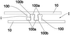
夹链袋利用夹链条来实现开启与关闭。请参阅图1和图2,现有技术的夹链条1是由两条可重复闭合和分离的夹链带10组成,所述两条夹链带10具有形状匹配的夹链结构100。夹链袋的袋体通常是由两个片材组成,所述两个片材的边缘相互熔接,以形成内部的空腔和连通所述空腔的开口。所述夹链条1设置于所述两个片材未熔接的区域中,位于所述两个片材之间,所述两条夹链带10分别熔接固定于所述两个片材的内侧。所述两条夹链带10的端部相互熔接,并且与所述两个片材熔接封合在一起,则图2中所述两条夹链带10的端部之间的缝隙I和缝隙i都消失了,从而实现密封。所述夹链袋通过所述两条夹链带10在中间部分相互闭合或分离来关闭或开启所述开口。The zipper bag uses a zipper chain to open and close. Please refer to FIG. 1 and FIG. 2 , the prior
然而,在现有夹链袋的熔接加工过程中,夹链条的端部边缘容易出现熔接不完全的问题,这使得夹链条中两条夹链带的端部之间产生空隙,或者使得夹链条的端部与袋体片材内侧的结合部位中产生空隙/气泡,从而导致夹链袋密封不良。例如图3的实物照片,其示出了现有技术的夹链条端部与袋体的熔接部位,由于袋体的材料具有一定的透明度,所以从袋体外部可清晰地看到内部的夹链条,该图3中的下方为上方的放大局部,从图中椭圆形的圈起部分可看出,在夹链条的端部边缘与袋体的熔接部位中存在鼓起的、熔接不全的部分,袋体的片材表面还出现了破洞,因而此夹链袋密封失效。However, during the welding process of the existing zipper bag, the end edge of the zipper chain is prone to the problem of incomplete welding, which causes a gap between the ends of the two zipper straps in the zipper chain, or makes the zipper chain Void/air bubbles are generated in the joint between the end of the zipper bag and the inside of the bag body sheet, resulting in poor sealing of the zipper bag. For example, the actual photo of FIG. 3 shows the welding part of the end of the clip chain and the bag body in the prior art. Since the material of the bag body has a certain degree of transparency, the internal clip chain can be clearly seen from the outside of the bag body. , the lower part in this Figure 3 is the enlarged part of the upper part, it can be seen from the circled part of the ellipse in the figure that there is a bulging and incomplete welding part in the welding part of the end edge of the clip chain and the bag body, Holes also appeared on the sheet surface of the bag body, so the zipper bag failed to seal.
针对上述的问题,专利文献CN210883334U公开了一种夹链袋密封结构,包含:In view of the above-mentioned problems, the patent document CN210883334U discloses a sealing structure for a zipper bag, including:
袋体,具有第一内侧壁、及面对所述第一内侧壁的第二内侧壁,所述第一内侧壁的一端与所述第二内侧壁的一端相互连接以形成熔接区;a bag body, having a first inner side wall and a second inner side wall facing the first inner side wall, one end of the first inner side wall and one end of the second inner side wall are connected to each other to form a welding area;
公扣夹链结构,设置于所述第一内侧壁,并具有两相对的公扣端部;a male buckle chain structure, which is arranged on the first inner side wall and has two opposite male buckle ends;
母扣夹链结构,设置于所述第二内侧壁且与所述公扣夹链结构受外力作用而相互分离或链合,并具有两相对的母扣端部;The female buckle chain structure is arranged on the second inner side wall and is separated from or linked with the male buckle chain structure under the action of external force, and has two opposite female buckle ends;
其中,相邻的所述母扣端部与所述公扣端部相互熔接成一体,以形成一体熔合且位于所述熔接区的熔接段,而且,所述熔接段是通过超音波熔接法熔接在该熔接区。Wherein, the adjacent ends of the female buckle and the ends of the male buckles are welded together into one body to form a welded section that is fused together and located in the welding area, and the welded section is welded by an ultrasonic welding method. in the fusion zone.
同样地,专利文献CN201472848U公开了一种密封包装袋,包括袋体和夹链,夹链为可重复开启和关闭的互相匹配的凸棱和凹槽,袋体两侧形成封合边,夹链开口宽度小于袋体的宽度,夹链处于袋体两侧的封合边之间,夹链两端形成封合面,减少开启后的夹链变形,吸收开启应力,从而提升夹链开启后重新闭合的真空密封性能;所述夹链两端的封合面与对应侧封合边封固于一起,形成袋体与夹链的贴体封合。所述封合面加固方式为封刀封合。Similarly, the patent document CN201472848U discloses a sealed packaging bag, including a bag body and a clip chain, the clip chain is a matching rib and groove that can be opened and closed repeatedly, the two sides of the bag body form sealing edges, and the clip chain The width of the opening is smaller than the width of the bag body, the clip chain is located between the sealing edges on both sides of the bag body, and the two ends of the clip chain form a sealing surface, which reduces the deformation of the clip chain after opening, absorbs the opening stress, and improves the re-opening of the clip chain after opening. Closed vacuum sealing performance; the sealing surfaces at both ends of the clip chain and the corresponding side sealing edges are sealed together to form a body-to-body sealing of the bag body and the clip chain. The sealing surface reinforcement method is sealing with a sealing knife.
专利文献CN210883334U和CN201472848U的方案都是在夹链条端部边缘额外施加熔接工序来增加熔接部位,从而加固夹链条的两条夹链带端部之间的封合以及夹链条端部与袋体侧部之间的封合。此种方法虽然可以增强密封性,但是存在以下缺陷:The solutions of the patent documents CN210883334U and CN201472848U both apply an additional welding process to the edge of the end of the clamping chain to increase the welding position, thereby strengthening the sealing between the ends of the two clamping strips of the clamping chain and the end of the clamping chain and the side of the bag body. seal between parts. Although this method can enhance the sealing, it has the following disadvantages:
(1)采取各种熔接加工方式例如镭射加工、高周波加工、超音波加工等,在夹链条端部和袋体侧部的原有材料上增加熔接部位,并不能从根本上解决由于夹链条中两条夹链带之间存在的断差、或者夹链条与袋体的形状不匹配难以贴合所导致的熔接不全的问题,上述方法不能彻底改善密封性。再次参考图3所示的例子,虽然在夹链条的端部边缘增加了锯齿状的熔接线,但仍然存在密封失效的问题。(1) Adopting various welding processing methods such as laser processing, high-frequency processing, ultrasonic processing, etc., adding welding parts to the original materials of the end of the clip chain and the side of the bag body cannot fundamentally solve the problem of the clip chain. The above method cannot completely improve the sealing performance due to the problem of incomplete fusion caused by the difference between the two clipping belts, or the mismatching of the shapes of the clipping chain and the bag body, which is difficult to fit. Referring again to the example shown in FIG. 3 , although a serrated weld line is added to the end edge of the clip chain, there is still a problem of seal failure.
(2)如果为了增强密封加固效果,在夹链条的两端过度熔接,加上夹链条断差较大的因素,容易造成袋体的片材表面皮料过度延展而破洞,反而导致袋体密封失效,过度熔接还会使夹链条的两端受到过度挤压,从而使得夹链条的中段被两端过度拉扯而产生变形,这可能导致两条夹链带不能严密地相互闭合,随之密封效果变差。如图3所示,在夹链条的端部边缘增加了锯齿状的熔接线,反而造成袋体的片材表面过度延展而产生破洞。(2) In order to enhance the sealing and reinforcement effect, excessive welding at both ends of the clip chain, coupled with the factor of large breakage of the clip chain, it is easy to cause excessive extension of the sheet surface leather of the bag body and holes, which will lead to the bag body. Seal failure, excessive welding will also cause the two ends of the clamp chain to be over-extruded, so that the middle section of the clamp chain is over-pulled by the two ends and deformed, which may cause the two clamp belts to not be tightly closed to each other, and then sealed The effect gets worse. As shown in FIG. 3 , a zigzag welding line is added to the end edge of the clip chain, which instead causes the surface of the sheet material of the bag body to be excessively stretched and a hole is generated.
(3)在夹链条的两端额外加工形成的熔接部位,较大程度地影响了夹链袋产品的外型美观,见图3。(3) The welding parts formed by additional processing at both ends of the clip chain greatly affect the appearance of the clip chain bag product, as shown in Figure 3.
发明内容SUMMARY OF THE INVENTION
为了克服前述现有技术的至少一个缺陷,本发明提供一种带有封端组件的夹链条,以改善夹链条端部的密封性,并且改善利用夹链条制作的夹链袋的密封性。In order to overcome at least one of the aforementioned drawbacks of the prior art, the present invention provides a clip chain with an end sealing assembly to improve the sealing performance of the end of the clip chain and improve the sealing performance of the clip chain bag made of the clip chain.
本发明采取的技术方案如下:The technical scheme adopted by the present invention is as follows:
一种夹链条,由两条分别具有夹链结构的夹链带组成,所述两条夹链带的夹链结构形状匹配,受外力作用可相互分离或配合,所述两条夹链带的夹链结构在端部相互配合;A clip chain is composed of two clip chain belts with clip chain structures respectively. The clip chain structures of the two clip chain belts are matched in shape, and can be separated or matched with each other under the action of external force. The clip chain structure cooperates with each other at the ends;
所述夹链条的两个端部各自设置有一个通过注塑工艺成型的封端组件;所述封端组件包括两个包覆层以及位于两个包覆层之间的连接部,所述两个包覆层分别包覆所述两条夹链带的端部表面,所述连接部连接所述两个包覆层,并填充所述两条夹链带的夹链结构在端部之间的缝隙。The two ends of the clip chain are each provided with an end-blocking assembly formed by an injection molding process; the end-blocking assembly includes two cladding layers and a connecting portion located between the two cladding layers, the two The cladding layer covers the end surfaces of the two zipper belts respectively, and the connecting portion connects the two cladding layers and fills the zipper structure of the two zipper belts between the ends. gap.
本发明使用可与夹链条结合的塑料,通过注塑工艺(射出工艺)在夹链条的端部设置所述封端组件,在制作所述封端组件的注塑工艺过程中,熔融塑料会渗入两条夹链带在端部相互配合的夹链结构之间的缝隙,因此形成的所述连接部完全填充该缝隙,增强了两条夹链带的端部之间的密封性。In the present invention, plastics that can be combined with the clip chain are used, and the end capping assembly is arranged at the end of the clip chain through an injection molding process (injection process). The gap between the zipper structures whose ends of the zipper tapes are matched with each other, and thus the formed connecting portion completely fills the gap, enhancing the tightness between the ends of the two zipper tapes.
更重要的是,相对于前述现有技术通过熔接工艺在夹链条端部和袋体的原有材料上增加形成熔接部位的做法,本发明在夹链条的端部设置注塑成型的封端组件,所述封端组件起到了填充作用,而现有技术在原有材料上所形成的熔接部位如熔接线等并不能起到填充作用。More importantly, compared with the practice of adding welding parts to the original material of the end of the clip chain and the bag body through the welding process in the prior art, the present invention is provided with an injection-molded end sealing component at the end of the clip chain, The end capping component plays a filling role, but the welding parts such as welding lines formed on the original material in the prior art cannot play a filling role.
在通过熔合加工利用所述夹链条制作夹链袋的过程中,所述封端组件的两个包覆层和连接部融合成一体,作为填充物完全填充于两条夹链带的端部之间的所有缝隙,并且与袋体片材的内侧熔接封合,则所述夹链条制作的夹链袋侧部形成一个完整的密封区域,由此有效改善了因为夹链条中两条夹链带之间存在的断差、或者夹链条与袋体的形状不匹配难以贴合所导致的熔接不全的问题,极大地提升了夹链袋的密封性和产品合格率。In the process of making a zipper bag by using the zipper chain through fusion processing, the two covering layers and the connecting part of the end-blocking component are fused into one body, and are completely filled between the ends of the two zipper strips as filler. All the gaps between the zipper and the inner side of the bag body sheet are welded and sealed, the side of the zipper bag made of the zipper chain forms a complete sealing area, thereby effectively improving the two zipper belts in the zipper chain. The problem of incomplete welding caused by the difference between the gaps or the mismatch of the shape of the clip chain and the bag body, which is difficult to fit, greatly improves the sealing performance of the clip chain bag and the product qualification rate.
另外,相对于前述现有技术,本发明的带有所述封端组件的夹链条所制作的夹链袋中,袋体的片材表面不会出现过度延展而破洞,夹链条不会产生过度变形,且由于无需设置额外的、过多的熔接部位,得到夹链袋产品的外型更加美观。In addition, compared with the aforementioned prior art, in the zipper bag made of the zipper chain with the end-sealing assembly of the present invention, the sheet surface of the bag body will not be excessively stretched to cause holes, and the zipper chain will not produce Excessive deformation, and because there is no need to set additional and excessive welding parts, the appearance of the zipper bag product is more beautiful.
作为进一步优选的方案,所述封端组件还包括两个桥接翼,所述两个桥接翼分别从所述两个包覆层向所述夹链条的端部外侧延伸形成。As a further preferred solution, the end capping assembly further includes two bridging wings, the two bridging wings are respectively formed to extend from the two cladding layers to the outer side of the end of the clip chain.
在通过熔合加工利用所述夹链条制作夹链袋的过程中,所述两个桥接翼起到“桥梁”的作用,分别将夹链条与袋体的两个片材连接起来,彻底解决了因为夹链条与袋体之间存在断差、两者形状不匹配难以贴合所导致的熔接不全的问题,增加后续加工的可行性。In the process of using the zipper chain to make the zipper bag through fusion processing, the two bridging wings play the role of "bridges", respectively connecting the zipper chain and the two sheets of the bag body, which completely solves the problem of There is a problem of incomplete welding caused by the difference between the clip chain and the bag body, and the mismatch of the shapes of the two, which is difficult to fit, which increases the feasibility of subsequent processing.
作为进一步优选的方案,所述封端组件中,所述连接部的外表面为倒圆面,其平滑连接所述两个桥接翼中相向的两个表面。此设置有利于减小制作夹链袋过程中两个桥接翼之间的断差,增加两个桥接翼相互结合的简易度与牢固性。As a further preferred solution, in the end capping assembly, the outer surface of the connecting portion is a rounded surface, which smoothly connects the two opposite surfaces of the two bridging wings. This arrangement is beneficial to reduce the break difference between the two bridging wings in the process of making the zipper bag, and increase the simplicity and firmness of the mutual combination of the two bridging wings.
作为进一步优选的方案,所述封端组件中,所述两个桥接翼分别沿所述两条夹链带所在的平面延伸形成。As a further preferred solution, in the end capping assembly, the two bridging wings are respectively formed to extend along the plane where the two clip belts are located.
作为进一步优选的方案,所述封端组件中,所述桥接翼的两端分别超出所述夹链条在宽度方向上的两侧,有利于增大桥接翼后续与袋体的结合面积,增强结合效果。As a further preferred solution, in the end sealing assembly, the two ends of the bridging wings are respectively beyond the two sides of the clip chain in the width direction, which is beneficial to increase the subsequent bonding area of the bridging wings and the bag body, and enhance the bonding Effect.
本发明还提供一种夹链袋,所述夹链袋包括:The present invention also provides a zipper bag, the zipper bag comprising:
袋体,由两个片材组成;所述两个片材通过熔接线彼此熔接封合,形成一个空腔和一个连通所述空腔的开口;The bag body is composed of two sheets; the two sheets are welded and sealed with each other through a welding line to form a cavity and an opening communicating with the cavity;
夹链条,设置于所述袋体的所述开口中,位于所述两个片材之间,由两条分别具有夹链结构的夹链带组成;所述两条夹链带分别与所述两个片材的内侧熔接封合;所述两条夹链带的夹链结构形状匹配,受外力作用可相互分离以开启所述开口,或者相互配合以关闭所述开口;所述两条夹链带的夹链结构在端部相互配合;The clip chain is arranged in the opening of the bag body, located between the two sheets, and is composed of two clip straps with clip chain structures respectively; the two clip straps are respectively connected with the The inner sides of the two sheets are welded and sealed; the zipper structures of the two zipper belts are matched in shape, and can be separated from each other by external force to open the opening, or cooperate with each other to close the opening; the two clips The clip chain structure of the chain belt cooperates with each other at the end;
所述夹链条的两个端部各自设置有一个封端组件;所述封端组件位于所述袋体的所述两个片材之间,包覆所述夹链条的端部表面,并填充所述两条夹链带的端部之间的缝隙;The two ends of the clip chain are each provided with an end sealing assembly; the end sealing assembly is located between the two sheets of the bag body, covers the end surface of the clip chain, and fills the gap between the ends of the two zipper belts;
所述封端组件是先通过注塑工艺初步成型于所述夹链条的端部,再通过熔接工艺加工而成的;所述夹链条的端部、所述封端组件和所述两个片材从内而外地熔接封合在一起,所述袋体中的所述熔接线分别与所述两个封端组件熔接封合。The end-blocking component is initially formed on the end of the clip chain by an injection molding process, and then processed by a welding process; the end of the clip chain, the end-blocking component and the two sheets They are welded and sealed together from the inside out, and the welding lines in the bag body are welded and sealed with the two end sealing components respectively.
作为进一步优选的方案,所述封端组件先通过注塑工艺成型为初步结构,所述初步结构包括两个包覆层、连接部和两个桥接翼,所述两个包覆层分别包覆所述两条夹链带的端部表面;所述连接部位于所述两个包覆层之间,连接所述两个包覆层,并填充所述两条夹链带的夹链结构在端部之间的缝隙;所述两个桥接翼分别从所述两个包覆层向所述夹链带的端部外侧延伸形成;As a further preferred solution, the end-blocking assembly is firstly formed into a preliminary structure by an injection molding process, and the preliminary structure includes two cladding layers, a connecting portion and two bridging wings, and the two cladding layers respectively cover the the end surfaces of the two zipper belts; the connecting portion is located between the two cladding layers, connects the two cladding layers, and fills the zipper structure of the two zipper belts at the ends The two bridging wings extend from the two cladding layers to the outer side of the end of the clip belt respectively;
所述封端组件再通过熔接工艺加工为,由所述两个包覆层、连接部和两个桥接翼融合得到的片状的最终结构,所述封端组件的最终结构的两表面分别与所述袋体的所述两个片材内侧熔接封合。The end-blocking assembly is then processed into a sheet-like final structure obtained by fusing the two cladding layers, the connecting portion and the two bridging wings through a welding process, and the two surfaces of the final structure of the end-blocking assembly are The inner sides of the two sheets of the bag body are welded and sealed.
作为进一步优选的方案,所述封端组件的初步结构中,所述连接部的外表面为倒圆面,其平滑连接所述两个桥接翼中相向的两个表面。As a further preferred solution, in the preliminary structure of the end capping assembly, the outer surface of the connecting portion is a rounded surface, which smoothly connects the two opposite surfaces of the two bridging wings.
作为进一步优选的方案,所述封端组件的初步结构中,所述桥接翼的两端分别超出所述夹链条在宽度方向上的两侧。As a further preferred solution, in the preliminary structure of the end capping assembly, the two ends of the bridging wing respectively extend beyond the two sides of the clamping chain in the width direction.
作为进一步优选的方案,所述袋体、所述夹链条和所述封端组件三者的材料相同。As a further preferred solution, the materials of the bag body, the clip chain and the end sealing assembly are the same.
为了更好地理解和实施,下面结合附图详细说明本发明。For better understanding and implementation, the present invention is described in detail below with reference to the accompanying drawings.
附图说明Description of drawings
图1为现有技术的一种夹链条的结构示意图;Fig. 1 is the structural representation of a kind of clip chain of the prior art;
图2为图1中L1方向的侧视图;Fig. 2 is the side view of L1 direction in Fig. 1;
图3为现有技术的夹链条端部与袋体的熔接部位的实物照片;Fig. 3 is the real photo of the welding part of the clip chain end of the prior art and the bag body;
图4为本发明的一个实施例中的带有封端组件的夹链条的结构示意图;4 is a schematic structural diagram of a clip chain with an end-capping assembly in an embodiment of the present invention;
图5为图4的夹链条的主视图;Fig. 5 is the front view of the clip chain of Fig. 4;
图6为图4的夹链条的前视图;Fig. 6 is the front view of the clip chain of Fig. 4;
图7为图5中A-A方向的剖视图;Fig. 7 is the sectional view of A-A direction in Fig. 5;
图8为图7中局部B的放大图;Fig. 8 is an enlarged view of part B in Fig. 7;
图9为图4的夹链条的侧视图;Figure 9 is a side view of the clip chain of Figure 4;
图10为本发明的一个实施例中的夹链袋的结构示意图;10 is a schematic structural diagram of a zipper bag in an embodiment of the present invention;
图11为带有封端组件的夹链条与袋体的组合图;Figure 11 is a combined view of a clip chain and a bag body with an end sealing assembly;
图12为图11中L方向的示意图;Fig. 12 is the schematic diagram of the L direction in Fig. 11;
图13为带有封端组件的夹链条的3D示意图;Figure 13 is a 3D schematic view of a clamp chain with an end cap assembly;
图14为利用带有封端组件的夹链条制作的夹链袋的3D示意图。Figure 14 is a 3D schematic view of a zipper bag made using a zipper chain with an end cap assembly.
附图中的虚线表示位于图示元件内部的结构。Dotted lines in the drawings indicate structures located inside the illustrated elements.
主要附图标记:夹链条1,夹链带10,夹链结构100,封端组件2,包覆层20,连接部21,倒圆面210,桥接翼22,定位片220,定位孔221,内凹空间23,袋体3,片材30,熔接线31,空腔32,开口33。Main reference signs:
具体实施方式Detailed ways
请参阅图4-9,图4-9示出了本发明的一个实施例中的夹链条1。Please refer to Figs. 4-9, Fig. 4-9 shows the
与现有技术的夹链条相同,本发明的夹链条1是由两条分别具有夹链结构100的夹链带10组成,所述两条夹链带10的夹链结构100形状相匹配,受外力作用可相互分离或相互配合,从而实现对开口的开启或关闭。Similar to the clip chain in the prior art, the
如本领域所公知的,本发明的两条夹链带10的夹链结构100有多种。例如图1-2所示,两条夹链带10的形状构造相同,两者的夹链结构100也相同,每个夹链结构100包括两条凸棱100a以及该两条凸棱100b之间所形成的凹槽102a;所述两条夹链带10的夹链结构100相互配合时,一个夹链结构100中的一条凸棱100a卡入另一个夹链结构100的凹槽100b内,从而实现密封,且所述两条夹链带10的长边有些许错落而不是对齐的。另外,两条夹链带10的夹链结构100也可以是其他的形状构造,还可以是互不相同的,例如,图12示出了本发明的夹链条与袋体的组合,该图12中一条夹链带10的夹链结构100具体为条形的卡凸100c,另一条夹链带10的夹链结构100具体为形状与之匹配的卡槽100d,所述两条夹链带10的夹链结构100相互配合,即所述卡凸100c卡入所述卡槽100d内,此时所述两条夹链带10的长边是对齐的。As known in the art, there are
区别于现有技术,本发明的创新之处在于,所述夹链带10的两个端部各自设置一个封端组件2,如图4-9所示,而且,所述两条夹链带10的夹链结构100在端部相互配合,由所述封端组件2连接固定在一起,所述两条夹链带10的夹链结构100的中间部分受外力作用可相互分离以开启开口,或者相互配合以关闭开口。Different from the prior art, the innovation of the present invention lies in that two end portions of the
所述封端组件2是附加到所述夹链条1上的塑料制品,其采用可以与所述夹链带10结合的塑料,是通过注塑工艺成型(塑胶射出成型)的,而不是由夹链带10或袋体的原有材料熔接加工形成的。The end-blocking
所述封端组件2包括两个包覆层20和连接部21。The
所述两个包覆层20分别包覆所述两条夹链带10的端部表面,也就是说,每个包覆层20覆盖对应夹链带10的端部的上表面、下表面和端面。The two
所述连接部21位于所述两个包覆层20之间,连接所述两个包覆层20。在制作所述封端组件2的注塑工艺过程中,熔融塑料会渗入所述两条夹链带10在端部相互配合的夹链结构100之间的缝隙(即图2中所示的缝隙i)中,从而达到填充效果。由此,所述连接部21填充所述两条夹链带10在端部相互配合的夹链结构100之间的缝隙。The connecting
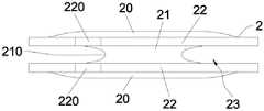
为了后续更好地与袋体结合,所述封端组件2还包括两个桥接翼22,在制作夹链袋时用于分别与袋体的两个片材熔接。所述两个桥接翼22分别从所述两个包覆层20向所述夹链条1的端部外侧延伸形成。具体地,如图6和图7所示,所述两个桥接翼22分别沿所述两条夹链带10所在的平面向外延伸,两者相互平行。更优地,如图5所示,所述桥接翼22的两端分别超出所述夹链条1在宽度方向即该图5中w方向上的两侧,有利于增大桥接翼22与袋体的结合面积,增强结合效果。In order to be better combined with the bag body later, the
图4和图5所示的实施例中,桥接翼22的外侧边为圆弧形,本领域的普通技术人员可以理解,在其他实施例中,桥接翼22还可以是其他形状。In the embodiments shown in FIGS. 4 and 5 , the outer sides of the bridging
为了减小熔接制作夹链袋过程中两个桥接翼22之间的断差,如图6、图7和图9所示,所述连接部21的外表面设计成一个倒圆面210,所述倒圆面210将所述两个桥接翼22中相向的两个表面平滑连接,使得两个桥接翼22之间通过圆弧渐变的方式过渡导顺。所述连接部21的倒圆面210与所述两个桥接翼22中相向的两个表面,形成了一个内凹空间23。In order to reduce the difference between the two bridging
所述夹链条1用于制作夹链袋的过程中,注塑成型于夹链条1端部的封端组件2会被施加熔接工艺,所述封端组件2中的两个包覆层20、连接部21和两个桥接翼22通过熔接工艺相互融合成一体,将所述两条夹链带10的端部之间的缝隙(即图2中所示的缝隙I)完全填充,同时前述的内凹空间23消失。In the process that the
为了在制作夹链袋的过程中更好地定位,所述封端组件2的两个桥接翼22分别设有一个定位孔221,所述两个桥接翼22的定位孔221在垂直于夹链带10所在平面的方向上位置对齐。如图4和图5所示的实施例中,所述桥接翼22的外侧边设有向外延伸形成的定位片220,在所述定位片220上开设有定位孔221。在其他实施例中,定位孔221还可以直接开设在桥接翼22上。For better positioning in the process of making the zipper bag, the two bridging
请参阅图10-14,图10示出了本发明的一个实施例中的夹链袋,所述夹链袋采用前述的带有封端组件2的夹链条1制作而成,其包括由两个片材30组成的袋体3;图11展示了在准备通过熔接工艺将夹链条1与片材30结合之前,需要将夹链条1放置在两个片材30之间的位置,图12为图11中L方向的示意图;图13为所述夹链条的3D示意图,图14为所述夹链袋的3D示意图,示出了所述夹链条与袋体的结合关系。Please refer to Figs. 10-14, Fig. 10 shows a zipper bag in an embodiment of the present invention, the zipper bag is made of the
所述袋体3的两个片材30通过熔接线31彼此熔接封合,以形成一个空腔32和一个开口33,所述开口连通所述空腔32与外部,如本领域所公知的。本领域的普通技术人员可以理解,所述袋体3的具体构造、片材30的形状和尺寸、开口33和熔接线31的布置等都不限于附图所示的实施例。The two
如图10所示,所述夹链条1设置于所述袋体3的所述开口33中,位于所述两个片材30之间,所述两条夹链带10分别与所述两个片材30的内侧熔接封合,所述两条夹链带10的夹链结构100受外力作用可相互分离以开启所述开口33,或者相互配合以关闭所述开口33。As shown in FIG. 10 , the
所述封端组件2是先通过前述的注塑工艺初步成型于所述夹链条1的端部,形成初步结构,再通过熔接工艺与所述袋体3结合,形成最终结构。以下进行详细说明。The
首先,所述封端组件2通过注塑工艺成型,得到的初步结构包括两个包覆层20和位于两个包覆层20之间的连接部21,还可以进一步包括两个桥接翼22。First, the
所述两个包覆层20分别包覆所述两条夹链带10的端部表面。所述连接部21连接所述两个包覆层20,并填充所述两条夹链带10在端部相互配合的夹链结构100之间的缝隙(即图2中所示的缝隙i)。The two covering
所述两个桥接翼22分别从所述两个包覆层20向所述夹链条1的端部外侧延伸形成。具体地,所述两个桥接翼22分别沿所述两条夹链带10所在的平面向外延伸,两者相互平行。更优地,所述桥接翼22的两端分别超出夹链条1在宽度方向上的两侧。为了方便定位,所述两个桥接翼22还可以分别设有一个定位孔221,所述两个定位孔221在垂直于夹链带10上下表面的方向上位置相互对齐。作为进一步优选的方案,所述连接部21的外表面为平滑连接所述两个桥接翼22中相向的两个表面的倒圆面210,见图12。The two
然后,经过熔接工艺加工,所述夹链条1的端部、封端组件2和两个片材30从内而外地熔接封合在一起,结合图11和12所示,而且,所述袋体3中的所述熔接线31的两端分别与所述两个封端组件2熔接封合,从而所述夹链袋产品制作完成,见图10。Then, through the welding process, the end of the
具体来说,在实施熔接工艺的过程中,每个封端组件2的初步结构中的两个包覆层20、连接部21和两个桥接翼22,经过加热后相互融合成一体,冷却后形成片状的最终结构,所述封端组件2的最终结构完全填充了两条夹链带10的端部之间的缝隙(即图2中所示的缝隙I和缝隙i);所述两个包覆层20分别与所述两个片材30的内侧熔接,所述两个桥接翼22也分别与所述两个片材30的内侧熔接,使得所述封端组件2的最终结构的两表面分别与所述两个片材30的内侧熔接封合。Specifically, in the process of implementing the welding process, the two
所述袋体3、夹链条1和封端组件2采用的塑料可相互结合,具体可以选择PU(聚氨酯)、TPU(热塑性聚氨酯弹性体橡胶)、PVC(聚氯乙烯)、ABS(丙烯腈-丁二烯-苯乙烯共聚物)等塑料。所述袋体3、夹链条1和封端组件2可以选用不同的塑料。为了增强结合效果,提高产品密封性,所述袋体3、夹链条1和封端组件2三者选用相同的塑料制作。The plastics used in the
所述熔接工艺可以是镭射加工、高周波加工、超音波加工等工艺。The welding process can be laser processing, high frequency processing, ultrasonic processing and other processes.
本领域的普通技术人员可以理解,封端组件2的形状和尺寸主要根据夹链条1和袋体3的形状结构和尺寸来确定,还可以结合考虑材料成本等其他因素来确定。Those of ordinary skill in the art can understand that the shape and size of the
以上所述实施例仅表达了本发明的几种实施方式,其描述较为具体和详细,但并不能因此而理解为对发明专利范围的限制。应当指出的是,对于本领域的普通技术人员来说,在不脱离本发明构思的前提下,还可以做出若干变形和改进,这些都属于本发明的保护范围。The above-mentioned embodiments only represent several embodiments of the present invention, and the descriptions thereof are specific and detailed, but should not be construed as a limitation on the scope of the invention patent. It should be pointed out that for those of ordinary skill in the art, without departing from the concept of the present invention, several modifications and improvements can also be made, which all belong to the protection scope of the present invention.
Claims (10)
Priority Applications (3)
| Application Number | Priority Date | Filing Date | Title |
|---|---|---|---|
| CN202210535700.5ACN115092523B (en) | 2022-05-17 | 2022-05-17 | Clip chain with end-capping assembly and clip chain bag |
| US17/863,373US12114741B2 (en) | 2022-05-17 | 2022-07-12 | Zipper structure and related zipper bag |
| DE102022120743.9ADE102022120743B4 (en) | 2022-05-17 | 2022-08-17 | ZIPPER STRUCTURE AND CORRESPONDING ZIPPER BAG |
Applications Claiming Priority (1)
| Application Number | Priority Date | Filing Date | Title |
|---|---|---|---|
| CN202210535700.5ACN115092523B (en) | 2022-05-17 | 2022-05-17 | Clip chain with end-capping assembly and clip chain bag |
Publications (2)
| Publication Number | Publication Date |
|---|---|
| CN115092523Atrue CN115092523A (en) | 2022-09-23 |
| CN115092523B CN115092523B (en) | 2023-08-15 |
Family
ID=83289501
Family Applications (1)
| Application Number | Title | Priority Date | Filing Date |
|---|---|---|---|
| CN202210535700.5AActiveCN115092523B (en) | 2022-05-17 | 2022-05-17 | Clip chain with end-capping assembly and clip chain bag |
Country Status (3)
| Country | Link |
|---|---|
| US (1) | US12114741B2 (en) |
| CN (1) | CN115092523B (en) |
| DE (1) | DE102022120743B4 (en) |
Families Citing this family (1)
| Publication number | Priority date | Publication date | Assignee | Title |
|---|---|---|---|---|
| CN115092523B (en)* | 2022-05-17 | 2023-08-15 | 立兆股份有限公司 | Clip chain with end-capping assembly and clip chain bag |
Citations (14)
| Publication number | Priority date | Publication date | Assignee | Title |
|---|---|---|---|---|
| DE4442830A1 (en)* | 1993-12-02 | 1995-06-14 | Ykk Corp | Melt forming tool for prodn. of end stops on continuous lengths of sliding clasp fastener |
| JPH08143057A (en)* | 1994-11-21 | 1996-06-04 | Akio Yokoi | Sealing structure for chuck end part of sealable bag |
| JP2000226042A (en)* | 1999-02-08 | 2000-08-15 | Teikoku Seiyaku Co Ltd | Chuck bag, method for producing the same, and seal bar used for the production |
| JP2002184299A (en)* | 2000-12-11 | 2002-06-28 | Toyota Auto Body Co Ltd | Structure for preventing operator from forgetting to tighten inclined tightening preventive terminal |
| JP2003026190A (en)* | 2001-07-19 | 2003-01-29 | Nisshin Flour Milling Inc | Packaging bag for powder |
| JP2003128090A (en)* | 2001-10-24 | 2003-05-08 | Dainippon Printing Co Ltd | Zippered bag, method for producing the same, and zipper opening side seal device used for the same |
| JP2006087452A (en)* | 2004-09-21 | 2006-04-06 | Dainippon Printing Co Ltd | Chuck tape and bag with chuck tape |
| JP2006282189A (en)* | 2005-03-31 | 2006-10-19 | Tokyo Autom Mach Works Ltd | Bag with zipper, zipper end molding apparatus, and apparatus for gluing zipper |
| JP2009051522A (en)* | 2007-08-24 | 2009-03-12 | Toppan Printing Co Ltd | Manufacturing method and manufacturing apparatus for bag with zipper |
| CN105595540A (en)* | 2016-01-12 | 2016-05-25 | 中山市骏坚服装拉链有限公司 | Method for manufacturing sealed waterproof zipper |
| JP2016198977A (en)* | 2015-04-13 | 2016-12-01 | 凸版印刷株式会社 | Film production method, film, solar cell module using the same, and laminated glass |
| US20180126661A1 (en)* | 2016-11-08 | 2018-05-10 | Ameriglobe, Llc | Stitchless bulk bag with heat fused seams and method of production |
| CN208102736U (en)* | 2018-04-20 | 2018-11-16 | 石狮市天马数控设备有限公司 | A kind of single side Transparent plastic pack bag |
| TWI705031B (en)* | 2019-07-03 | 2020-09-21 | 羅振益 | Sealing structure of clip chain bag |
Family Cites Families (15)
| Publication number | Priority date | Publication date | Assignee | Title |
|---|---|---|---|---|
| US2674289A (en)* | 1951-02-02 | 1954-04-06 | Silverman | |
| US2746502A (en)* | 1954-02-15 | 1956-05-22 | Graell Alberto Camprubi | Bag with integral closing means |
| US5161286A (en)* | 1991-03-22 | 1992-11-10 | Mobil Oil Corporation | End clamp stops for plastic reclosable fastener |
| US5836056A (en)* | 1996-09-10 | 1998-11-17 | S. C. Johnson Home Storage Inc. | Reclosable fastener assembly |
| US6928702B1 (en)* | 1999-06-10 | 2005-08-16 | The Glad Products Company | Closure device |
| US6508969B1 (en) | 2000-08-10 | 2003-01-21 | Pactiv Corporation | Injection-molded end stop for a slider-operated fastener |
| US6569368B2 (en) | 2001-07-31 | 2003-05-27 | Illinois Tool Works Inc. | Method for manufacturing a plastic zipper with end stops |
| US7040808B2 (en)* | 2002-03-20 | 2006-05-09 | Pactiv Corporation | Reclosable bags with tamper evident features and methods of making the same |
| US20070177827A1 (en)* | 2006-01-30 | 2007-08-02 | Reynolds Consumer Products, Inc. | Slider end stop for a reclosable bag and methods |
| MX358565B (en)* | 2009-10-08 | 2018-08-24 | Illinois Tool Works Inc Star | Carton with plastic reclosable header. |
| US8690430B2 (en)* | 2012-06-20 | 2014-04-08 | S.C. Johnson & Son, Inc. | Storage bag having a slider with ridges that presses together and separates interlocking profiles of fastener strips |
| US20140216969A1 (en)* | 2013-02-04 | 2014-08-07 | Gabe Cherian | Edg1 easy open edge |
| US10303210B2 (en)* | 2016-08-15 | 2019-05-28 | Apple Inc. | Electronic devices with wrist straps |
| US11772849B2 (en)* | 2021-06-18 | 2023-10-03 | S. C. Johnson & Son, Inc. | Closure system for pouch or container |
| CN115092523B (en)* | 2022-05-17 | 2023-08-15 | 立兆股份有限公司 | Clip chain with end-capping assembly and clip chain bag |
- 2022
- 2022-05-17CNCN202210535700.5Apatent/CN115092523B/enactiveActive
- 2022-07-12USUS17/863,373patent/US12114741B2/enactiveActive
- 2022-08-17DEDE102022120743.9Apatent/DE102022120743B4/enactiveActive
Patent Citations (14)
| Publication number | Priority date | Publication date | Assignee | Title |
|---|---|---|---|---|
| DE4442830A1 (en)* | 1993-12-02 | 1995-06-14 | Ykk Corp | Melt forming tool for prodn. of end stops on continuous lengths of sliding clasp fastener |
| JPH08143057A (en)* | 1994-11-21 | 1996-06-04 | Akio Yokoi | Sealing structure for chuck end part of sealable bag |
| JP2000226042A (en)* | 1999-02-08 | 2000-08-15 | Teikoku Seiyaku Co Ltd | Chuck bag, method for producing the same, and seal bar used for the production |
| JP2002184299A (en)* | 2000-12-11 | 2002-06-28 | Toyota Auto Body Co Ltd | Structure for preventing operator from forgetting to tighten inclined tightening preventive terminal |
| JP2003026190A (en)* | 2001-07-19 | 2003-01-29 | Nisshin Flour Milling Inc | Packaging bag for powder |
| JP2003128090A (en)* | 2001-10-24 | 2003-05-08 | Dainippon Printing Co Ltd | Zippered bag, method for producing the same, and zipper opening side seal device used for the same |
| JP2006087452A (en)* | 2004-09-21 | 2006-04-06 | Dainippon Printing Co Ltd | Chuck tape and bag with chuck tape |
| JP2006282189A (en)* | 2005-03-31 | 2006-10-19 | Tokyo Autom Mach Works Ltd | Bag with zipper, zipper end molding apparatus, and apparatus for gluing zipper |
| JP2009051522A (en)* | 2007-08-24 | 2009-03-12 | Toppan Printing Co Ltd | Manufacturing method and manufacturing apparatus for bag with zipper |
| JP2016198977A (en)* | 2015-04-13 | 2016-12-01 | 凸版印刷株式会社 | Film production method, film, solar cell module using the same, and laminated glass |
| CN105595540A (en)* | 2016-01-12 | 2016-05-25 | 中山市骏坚服装拉链有限公司 | Method for manufacturing sealed waterproof zipper |
| US20180126661A1 (en)* | 2016-11-08 | 2018-05-10 | Ameriglobe, Llc | Stitchless bulk bag with heat fused seams and method of production |
| CN208102736U (en)* | 2018-04-20 | 2018-11-16 | 石狮市天马数控设备有限公司 | A kind of single side Transparent plastic pack bag |
| TWI705031B (en)* | 2019-07-03 | 2020-09-21 | 羅振益 | Sealing structure of clip chain bag |
Non-Patent Citations (3)
| Title |
|---|
| 刘军;: "201仪表板注塑模具斜抽芯崩口成因分析与对策", 装备制造技术, no. 08* |
| 苏霞;: "先进复合材料制造技术", 橡塑技术与装备, no. 24* |
| 赵一霖;: "热缩管与热缩带", 电子制作, no. 06* |
Also Published As
| Publication number | Publication date |
|---|---|
| DE102022120743B4 (en) | 2024-05-16 |
| CN115092523B (en) | 2023-08-15 |
| US20230371658A1 (en) | 2023-11-23 |
| DE102022120743A1 (en) | 2023-11-23 |
| US12114741B2 (en) | 2024-10-15 |
Similar Documents
| Publication | Publication Date | Title |
|---|---|---|
| KR100231232B1 (en) | End clamp stops for plastic reclosable fastener | |
| JP4351403B2 (en) | Zipper bag and manufacturing method thereof | |
| US4787754A (en) | Reclosable flexible bags having fastener profiles attached to exterior walls thereof and a method of making same | |
| US7441312B2 (en) | Sealing slide fastener with teeth welded onto the tapes which they join | |
| JP3236301B2 (en) | Fasteners for bags | |
| US7107738B2 (en) | Tamper-evident reclosable bag having slider-actuated string zipper | |
| JP4546061B2 (en) | Bag with slide fastener | |
| EP2045191B1 (en) | Packaging bag with fastener tape | |
| US20090022435A1 (en) | Zipper tape, packing bag with zipper tape and apparatus for producing packing bag with zipper tape | |
| EP0834454B1 (en) | Bags with plastic fasteners and method of manufacturing the same | |
| EP1749652A1 (en) | Method for installing closure in mouth of pre-made bag | |
| US20070098305A1 (en) | Slider End Stop For A Reclosable Bag and Methods | |
| US20050252816A1 (en) | Process for producing compression bag and compression bag | |
| CN115092523A (en) | Chain and Chain Bags with End Caps | |
| US20040066984A1 (en) | Built-in zipper bag and manufacturing method thereof | |
| US20070177827A1 (en) | Slider end stop for a reclosable bag and methods | |
| CN107848668B (en) | Bag with zipper seal and side gussets and method for making such a bag | |
| TW202122005A (en) | Tape, zipper tape, and container with tape and method for manufacture therefor | |
| EP1447339A1 (en) | Tamper evident bag with slider actuated zipper | |
| JP4454629B2 (en) | Zipper container manufacturing method | |
| TW202323022A (en) | Container, method for manufacturing container, device for manufacturing container, seal bar, and film assembly | |
| JP2011042398A (en) | Bag with zipper and method for manufacturing the same | |
| JP6847571B2 (en) | Fitting tool and bag with fitting tool | |
| JP4204884B2 (en) | Plastic bag | |
| CN220975124U (en) | Sealing bag |
Legal Events
| Date | Code | Title | Description |
|---|---|---|---|
| PB01 | Publication | ||
| PB01 | Publication | ||
| SE01 | Entry into force of request for substantive examination | ||
| SE01 | Entry into force of request for substantive examination | ||
| GR01 | Patent grant | ||
| GR01 | Patent grant |