CN115089917A - A cardiac rehabilitation training device after interventional cardiology - Google Patents
A cardiac rehabilitation training device after interventional cardiologyDownload PDFInfo
- Publication number
- CN115089917A CN115089917ACN202210869254.1ACN202210869254ACN115089917ACN 115089917 ACN115089917 ACN 115089917ACN 202210869254 ACN202210869254 ACN 202210869254ACN 115089917 ACN115089917 ACN 115089917A
- Authority
- CN
- China
- Prior art keywords
- rod
- driving
- limiting
- gear
- pressure
- Prior art date
- Legal status (The legal status is an assumption and is not a legal conclusion. Google has not performed a legal analysis and makes no representation as to the accuracy of the status listed.)
- Withdrawn
Links
- 238000002554cardiac rehabilitationMethods0.000titledescription6
- 210000003141lower extremityAnatomy0.000claimsabstractdescription24
- 230000005540biological transmissionEffects0.000claimsabstractdescription19
- 210000001364upper extremityAnatomy0.000claimsabstractdescription17
- 238000013016dampingMethods0.000claimsabstractdescription10
- 238000000034methodMethods0.000claimsdescription4
- 238000003825pressingMethods0.000claimsdescription4
- 230000000149penetrating effectEffects0.000claimsdescription2
- 238000011084recoveryMethods0.000claims7
- 230000001755vocal effectEffects0.000claims4
- 210000000080chela (arthropods)Anatomy0.000claims1
- 230000002980postoperative effectEffects0.000claims1
- 238000009434installationMethods0.000description12
- 238000010586diagramMethods0.000description10
- 230000001105regulatory effectEffects0.000description3
- 230000000747cardiac effectEffects0.000description2
- 230000007547defectEffects0.000description2
- 238000003745diagnosisMethods0.000description2
- 230000000694effectsEffects0.000description2
- 208000024172Cardiovascular diseaseDiseases0.000description1
- 238000006073displacement reactionMethods0.000description1
- 238000005096rolling processMethods0.000description1
- 238000001356surgical procedureMethods0.000description1
Images


Classifications
- A—HUMAN NECESSITIES
- A63—SPORTS; GAMES; AMUSEMENTS
- A63B—APPARATUS FOR PHYSICAL TRAINING, GYMNASTICS, SWIMMING, CLIMBING, OR FENCING; BALL GAMES; TRAINING EQUIPMENT
- A63B21/00—Exercising apparatus for developing or strengthening the muscles or joints of the body by working against a counterforce, with or without measuring devices
- A63B21/00058—Mechanical means for varying the resistance
- A63B21/00069—Setting or adjusting the resistance level; Compensating for a preload prior to use, e.g. changing length of resistance or adjusting a valve
- A—HUMAN NECESSITIES
- A63—SPORTS; GAMES; AMUSEMENTS
- A63B—APPARATUS FOR PHYSICAL TRAINING, GYMNASTICS, SWIMMING, CLIMBING, OR FENCING; BALL GAMES; TRAINING EQUIPMENT
- A63B21/00—Exercising apparatus for developing or strengthening the muscles or joints of the body by working against a counterforce, with or without measuring devices
- A63B21/012—Exercising apparatus for developing or strengthening the muscles or joints of the body by working against a counterforce, with or without measuring devices using frictional force-resisters
- A63B21/015—Exercising apparatus for developing or strengthening the muscles or joints of the body by working against a counterforce, with or without measuring devices using frictional force-resisters including rotating or oscillating elements rubbing against fixed elements
- A—HUMAN NECESSITIES
- A63—SPORTS; GAMES; AMUSEMENTS
- A63B—APPARATUS FOR PHYSICAL TRAINING, GYMNASTICS, SWIMMING, CLIMBING, OR FENCING; BALL GAMES; TRAINING EQUIPMENT
- A63B21/00—Exercising apparatus for developing or strengthening the muscles or joints of the body by working against a counterforce, with or without measuring devices
- A63B21/02—Exercising apparatus for developing or strengthening the muscles or joints of the body by working against a counterforce, with or without measuring devices using resilient force-resisters
- A63B21/055—Exercising apparatus for developing or strengthening the muscles or joints of the body by working against a counterforce, with or without measuring devices using resilient force-resisters extension element type
- A—HUMAN NECESSITIES
- A63—SPORTS; GAMES; AMUSEMENTS
- A63B—APPARATUS FOR PHYSICAL TRAINING, GYMNASTICS, SWIMMING, CLIMBING, OR FENCING; BALL GAMES; TRAINING EQUIPMENT
- A63B22/00—Exercising apparatus specially adapted for conditioning the cardio-vascular system, for training agility or co-ordination of movements
- A63B22/06—Exercising apparatus specially adapted for conditioning the cardio-vascular system, for training agility or co-ordination of movements with support elements performing a rotating cycling movement, i.e. a closed path movement
- A63B22/0605—Exercising apparatus specially adapted for conditioning the cardio-vascular system, for training agility or co-ordination of movements with support elements performing a rotating cycling movement, i.e. a closed path movement performing a circular movement, e.g. ergometers
- A—HUMAN NECESSITIES
- A63—SPORTS; GAMES; AMUSEMENTS
- A63B—APPARATUS FOR PHYSICAL TRAINING, GYMNASTICS, SWIMMING, CLIMBING, OR FENCING; BALL GAMES; TRAINING EQUIPMENT
- A63B23/00—Exercising apparatus specially adapted for particular parts of the body
- A63B23/035—Exercising apparatus specially adapted for particular parts of the body for limbs, i.e. upper or lower limbs, e.g. simultaneously
- A63B23/12—Exercising apparatus specially adapted for particular parts of the body for limbs, i.e. upper or lower limbs, e.g. simultaneously for upper limbs or related muscles, e.g. chest, upper back or shoulder muscles
- A63B23/1209—Involving a bending of elbow and shoulder joints simultaneously
Landscapes
- Health & Medical Sciences (AREA)
- Orthopedic Medicine & Surgery (AREA)
- General Health & Medical Sciences (AREA)
- Physical Education & Sports Medicine (AREA)
- Life Sciences & Earth Sciences (AREA)
- Biophysics (AREA)
- Cardiology (AREA)
- Vascular Medicine (AREA)
- Rehabilitation Tools (AREA)
Abstract
Description
Translated fromChinese技术领域technical field
本发明涉及康复训练领域,具体涉及一种心内科介入术后心脏康复训练装置。The invention relates to the field of rehabilitation training, in particular to a cardiac rehabilitation training device after interventional cardiology.
背景技术Background technique
心内科介入手术是心内科医生为诊断或治疗心血管疾病常用的诊疗技术之一,介入术后患者提供优质医疗与专科护理同时,康复锻炼越来越引起临床广泛重视,特别是早期心脏功能的康复训练,由于患者身体较为虚弱且不可进行剧烈运动,因此运动训练多在室内进行,目前较为常见的训练装置有室内单车,其可为患者提供较为舒适且有效的康复训练。Cardiac interventional surgery is one of the commonly used diagnosis and treatment techniques by cardiologists for the diagnosis or treatment of cardiovascular diseases. After intervention, patients are provided with high-quality medical care and specialized care. Rehabilitation training, because the patient's body is relatively weak and cannot perform strenuous exercise, so the exercise training is mostly carried out indoors. At present, the more common training device is an indoor bicycle, which can provide patients with more comfortable and effective rehabilitation training.
目前,现有的室内单车其运动阻力可以调节,因此可以根据患者的身体状况进行运动阻力的调节,但是,患者在踩踏时,其双脚踩踏的阻力相同,无法调节两只脚各自的踩踏阻力,不适合部分腿部缺陷的患者。At present, the exercise resistance of the existing indoor bicycles can be adjusted, so the exercise resistance can be adjusted according to the physical condition of the patient. However, when the patient pedals, the pedaling resistance of both feet is the same, and the pedaling resistance of the two feet cannot be adjusted. , not suitable for patients with partial leg defects.
因此,发明一种心内科介入术后心脏康复训练装置来解决上述问题很有必要。Therefore, it is necessary to invent a cardiac rehabilitation training device after interventional cardiology to solve the above problems.
发明内容SUMMARY OF THE INVENTION
本发明的目的是提供一种心内科介入术后心脏康复训练装置,以解决技术中训练装置无法调节两只脚各自的踩踏阻力,不适合部分腿部缺陷的患者的问题。The purpose of the present invention is to provide a cardiac rehabilitation training device after interventional cardiology, so as to solve the problem that the training device cannot adjust the respective stepping resistance of the two feet and is not suitable for some patients with leg defects.
为了实现上述目的,本发明提供如下技术方案:一种心内科介入术后心脏康复训练装置,包括基座、安装在基座顶部供心内科患者坐靠的座椅、安装在基座顶部的壳体,以及安装在壳体上供心内科患者双脚踩踏的下肢训练机构,所述壳体内部设置有为心内科患者双脚踩踏提供不同阻力的双脚阻尼机构,所述壳体顶部设置有供心内科患者上肢锻炼的上肢训练机构;In order to achieve the above purpose, the present invention provides the following technical solutions: a cardiac rehabilitation training device after interventional cardiology, comprising a base, a seat installed on the top of the base for patients in the department of cardiology to sit on, and a shell installed on the top of the base body, and a lower limb training mechanism installed on the casing for the feet of cardiology patients to step on, the casing is provided with a double-foot damping mechanism that provides different resistance for the feet of cardiology patients to step on, and the top of the casing is provided with Upper limb training institutions for upper limb exercise for cardiology patients;
所述下肢训练机构包括贯穿壳体的轴杆、与轴杆相连接的转盘、分别安装在轴杆两端的用于驱动轴杆转动的两个曲柄,以及与曲柄活动连接的供心内科患者足部踩踏的脚踏;The lower limb training mechanism includes a shaft penetrating through the housing, a turntable connected with the shaft, two cranks respectively installed at both ends of the shaft for driving the shaft to rotate, and a foot for cardiac medical patients movably connected with the crank. foot pedal;
所述双脚阻尼机构包括设置在转盘一侧为转盘旋转提供阻力的制动组件,以及为制动组件提供压力抵紧转盘并根据双脚踩踏交替变换压力的制动交替组件;The double-foot damping mechanism includes a brake assembly arranged on one side of the turntable to provide resistance for the turntable to rotate, and a brake alternation assembly that provides pressure for the brake assembly to press against the turntable and alternately changes the pressure according to the stepping of both feet;
所述上肢训练机构包括两个用于心内科患者双手推举训练的摆杆,以及为摆杆提供阻力的拉力弹簧。The upper limb training mechanism includes two pendulum bars used for bimanual press training for cardiology patients, and a tension spring for providing resistance to the pendulum bars.
优选的,所述制动组件包括与转盘相匹配的制动刹钳、用于支撑并限位制动刹钳的限位件,以及用于连接制动刹钳并配合制动交替组件为制动刹钳施加压力的连接件。Preferably, the brake assembly includes a brake caliper matched with the turntable, a limiter for supporting and limiting the brake caliper, and a brake caliper for connecting the brake caliper and cooperating with the brake alternation component The connecting piece that applies pressure to the brake caliper.
优选的,所述制动刹钳包括接触转盘用于产生摩擦阻力的刹车片、设置在刹车片一侧的用于连接限位件的限位片、开设在限位片上的两组导向滑槽,以及安装在限位片一侧用于与连接件组装的呈T形的连接片;Preferably, the brake caliper includes a brake pad contacting the turntable for generating frictional resistance, a limit piece disposed on one side of the brake pad for connecting the limit piece, and two sets of guide chutes formed on the limit piece , and a T-shaped connecting piece installed on one side of the limiting piece for assembling with the connecting piece;
两组导向滑槽均水平设置且关于限位片横向中心轴线呈轴对称分布;The two sets of guide chutes are arranged horizontally and distributed axisymmetrically with respect to the lateral center axis of the limit piece;
所述限位件包括安装在壳体内部呈匚形的安装架、设置在安装架一侧与限位片相匹配的安装槽,以及两组与导向滑槽相匹配的限位螺栓;The limiting member includes a mounting bracket installed inside the casing and is in a shape of a groove, a mounting groove arranged on one side of the mounting bracket to match the limiting piece, and two sets of limiting bolts matching the guide chute;
所述限位螺栓贯穿安装架和安装槽,所述限位螺栓的端部与安装槽的一侧壁螺纹连接,所述限位螺栓的中段贯穿导向滑槽并与导向滑槽滑动连接;The limit bolt penetrates through the mounting frame and the installation groove, the end of the limit bolt is threadedly connected with a side wall of the installation groove, and the middle section of the limit bolt penetrates the guide chute and is slidably connected with the guide chute;
所述连接件包括贯穿安装架并与安装架滑动连接的连接杆、开设在连接杆一端与连接片相匹配的卡槽、安装在连接杆另一端用于配合制动交替组件为制动刹钳施加压力的挡板,以及套设在连接杆外部且两端分别与挡板和安装架相连接的复位弹簧一。The connecting piece includes a connecting rod that penetrates through the mounting frame and is slidably connected to the mounting frame, a slot that is opened at one end of the connecting rod to match the connecting piece, and is installed at the other end of the connecting rod to cooperate with the braking alternate component as a brake caliper. A baffle for applying pressure, and a
优选的,所述制动交替组件包括两个呈半圆形的驱动轮、两组设置在挡板一侧给挡板施加压力的驱动件、用于支撑两个驱动件的固定轴,以及用于连接驱动轮和驱动件的传动件。Preferably, the braking alternation assembly includes two semicircular driving wheels, two sets of driving members arranged on one side of the baffle to apply pressure to the baffle, a fixed shaft for supporting the two driving members, and a It is used to connect the drive wheel and the drive member.
优选的,两个驱动轮呈上下对称分布且分别连接在转盘的两侧,用于在转盘转动时交替为挡板施加压力;Preferably, the two driving wheels are distributed symmetrically up and down and are respectively connected to both sides of the turntable, so as to alternately apply pressure to the baffle plate when the turntable rotates;
所述驱动件包括中段与固定轴转动连接的驱动杆、以及活动连接在驱动杆一端与挡板相接触的滚轮一;The driving member comprises a driving rod whose middle section is rotatably connected with the fixed shaft, and a
所述传动件包括与驱动杆相对应的滚轮二、与驱动轮相对应的滚轮三、连接滚轮二和滚轮三用于滚轮二和滚轮三之间压力调节的压力调节组件,以及设置在压力调节组件外部用于支撑压力调节组件的套管。The transmission element includes a
优选的,所述压力调节组件包括与套管滑动连接且一端与滚轮二相连接的导向杆一、与套管滑动连接且与端与滚轮三相连接的导向杆二、两端分别连接导向杆一和导向杆二的呈冂形的限位拉杆、一端与导向杆一相连接的调节弹簧、一端与导向杆二转动连接的调节螺栓、设置在调节弹簧与调节螺栓之间的滑杆、安装在调节螺栓外部的齿轮一、啮合在齿轮一一侧竖直设置的齿条一,以及用于支撑齿条一的竖杆;Preferably, the pressure regulating assembly includes a
所述滑杆一端与调节弹簧相连接,所述滑杆另一端与调节螺栓螺纹连接,所述齿轮一与开设有限位槽的调节螺栓的光杆部分滑动连接,所述竖杆与壳体滑动连接,所述竖杆顶端贯穿壳体并延伸出壳体顶部,所述壳体顶部安装有与竖杆相对应的指针,所述竖杆靠近指针的一侧设置有与指针相对应的刻度条。One end of the sliding rod is connected with the adjusting spring, the other end of the sliding rod is threadedly connected with the adjusting bolt, the first gear is slidingly connected with the polished rod part of the adjusting bolt with the limiting groove, and the vertical rod is slidingly connected with the housing The top of the vertical rod penetrates through the casing and extends out of the top of the casing, the top of the casing is provided with a pointer corresponding to the vertical rod, and the side of the vertical rod close to the pointer is provided with a scale bar corresponding to the pointer.
优选的,所述套管数量设置为两个,所述导向杆一和导向杆二分别与两个套管滑动连接,所述套管与壳体相连接,所述齿轮一设置在两个套管之间,所述限位拉杆设置在套管顶部,所述套管顶部开设有与限位拉杆相匹配的限位滑槽一,所述导向杆二顶部开设有与限位拉杆相匹配的限位滑槽二,所述限位拉杆一端与导向杆一固定安装,所述限位拉杆另一端与限位滑槽二滑动连接。Preferably, the number of the sleeves is set to two, the first guide rod and the second guide rod are respectively slidably connected to the two sleeves, the sleeves are connected to the housing, and the first gear is provided in the two sleeves. Between the pipes, the limit pull rod is arranged on the top of the sleeve, the top of the sleeve is provided with a
优选的,所述摆杆包括呈L形的驱动柄、设置在驱动柄外部的呈扇形的齿轮二、设置在驱动柄与齿轮二之间的套筒,以及连接驱动柄与齿轮二的连接组件。Preferably, the rocking rod comprises an L-shaped drive handle, a sector-
优选的,所述套筒安装在壳体内侧,所述套筒贯穿齿轮二并与齿轮二转动连接,所述驱动柄一端依次贯穿壳体和套筒并与壳体和套筒转动连接;Preferably, the sleeve is installed inside the casing, the sleeve penetrates the second gear and is rotatably connected with the second gear, and one end of the driving handle sequentially penetrates the casing and the sleeve and is rotatably connected with the casing and the sleeve;
所述连接组件包括安装在驱动柄顶端的手柄、活动安装在驱动柄另一端的压块、连接在压块和手柄之间的连接线,以及用于压块复位的复位弹簧二。The connecting assembly includes a handle mounted on the top end of the drive handle, a pressure block movably mounted on the other end of the drive handle, a connection line connected between the pressure block and the handle, and a return spring II for the reset of the pressure block.
优选的,所述竖杆一侧设置有齿条二,所述齿轮二设置在齿条二一侧并通过齿轮与齿条二传动连接,所述拉力弹簧一端与壳体相连接,所述拉力弹簧另一端安装有挂钩,所述驱动柄一侧等距设置有多个与挂钩相对应的环扣,所述壳体两侧安装有用于限位驱动柄的限位柱。Preferably, a second rack is provided on one side of the vertical rod, the second gear is arranged on one side of the second rack and is connected to the second rack through a gear, and one end of the tension spring is connected with the housing, and the tension spring is connected to the housing. A hook is installed on the other end of the spring, a plurality of loops corresponding to the hooks are arranged at equal distances on one side of the driving handle, and limit posts for limiting the driving handle are installed on both sides of the housing.
在上述技术方案中,本发明提供的技术效果和优点:In the above-mentioned technical scheme, the technical effects and advantages provided by the present invention:
1、通过设置两个半圆状的驱动轮,半圆状的驱动轮可以在转盘转动180°的范围内持续的通过传动件和驱动件为制动组件施压,然后转动半圈后,另一个驱动轮与传动件接触,使转盘每转动半圈切换一次对转盘的阻力,使两个驱动轮分别为心内科患者两只脚提供踩踏阻力,与现有的训练单车相比,可以为患者的两只脚分别提供阻力,使其更适合不同的使用人群;1. By setting two semi-circular driving wheels, the semi-circular driving wheels can continuously apply pressure to the brake assembly through the transmission parts and the driving parts within the range of 180° of the turntable, and then rotate half a circle, the other drive The wheels are in contact with the transmission parts, so that the turntable switches the resistance to the turntable every half a turn, so that the two driving wheels provide pedaling resistance for the two feet of the cardiology patient respectively. Each foot provides resistance separately, making it more suitable for different users;
2、通过手部抓住驱动柄的顶端,向外推动驱动柄,而拉力弹簧向内拉动驱动柄,为上肢训练提供阻力,进行上肢训练,而通过捏住驱动柄顶端的手柄,可以连接驱动柄和齿轮二,可以通过驱动柄带动齿轮二,进而调节下肢训练机构的阻力,与现有训练装置相比,不仅能进行上肢训练,还能进行下肢训练机构的阻力调节。2. Grasp the top of the drive handle with your hands, push the drive handle outward, and the tension spring pulls the drive handle inward, providing resistance for upper body training, and for upper body training, and by pinching the handle at the top of the drive handle, you can connect the drive handle The handle and the second gear can drive the second gear through the driving handle to adjust the resistance of the lower limb training mechanism. Compared with the existing training device, it can not only perform upper limb training, but also adjust the resistance of the lower limb training mechanism.
附图说明Description of drawings
为了更清楚地说明本申请实施例或现有技术中的技术方案,下面将对实施例中所需要使用的附图作简单地介绍,显而易见地,下面描述中的附图仅仅是本发明中记载的一些实施例,对于本领域普通技术人员来讲,还可以根据这些附图获得其他的附图。In order to more clearly illustrate the embodiments of the present application or the technical solutions in the prior art, the accompanying drawings required in the embodiments will be briefly introduced below. Obviously, the accompanying drawings in the following description are only described in the present invention. For some of the embodiments, those of ordinary skill in the art can also obtain other drawings according to these drawings.
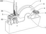
图1为本发明的整体结构示意图;Fig. 1 is the overall structure schematic diagram of the present invention;
图2为本发明壳体内部的局部结构示意图;Fig. 2 is the partial structure schematic diagram inside the casing of the present invention;
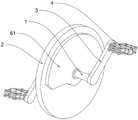
图3为本发明下肢训练机构的整体结构示意图;Fig. 3 is the overall structure schematic diagram of the lower limb training mechanism of the present invention;
图4为本发明图1的B部结构放大图;FIG. 4 is an enlarged view of the structure of part B of FIG. 1 of the present invention;
图5为本发明图1的A部结构放大图;FIG. 5 is an enlarged view of the structure of part A of FIG. 1 of the present invention;
图6为本发明两个驱动轮的配合结构示意图;6 is a schematic diagram of the matching structure of two driving wheels of the present invention;
图7为本发明制动组件和制动交替组件在壳体内部的配合图;Fig. 7 is the matching diagram of the brake assembly and the brake alternation assembly of the present invention inside the housing;
图8为本发明制动组件和制动交替组件的配合结构示意图;8 is a schematic diagram of the matching structure of the brake assembly and the brake alternation assembly of the present invention;
图9为本发明制动组件的爆炸图;Figure 9 is an exploded view of the brake assembly of the present invention;
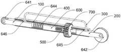
图10为本发明传动件的内部结构示意图;10 is a schematic diagram of the internal structure of the transmission element of the present invention;
图11为本发明驱动件与固定轴的配合结构示意图;11 is a schematic diagram of the matching structure of the driving member and the fixed shaft of the present invention;
图12为本发明摆杆的立体结构示意图;Fig. 12 is the three-dimensional structure schematic diagram of the pendulum rod of the present invention;
图13为本发明图12的C部结构放大图;FIG. 13 is an enlarged view of the structure of the C part of FIG. 12 of the present invention;
图14为本发明摆杆的局部爆炸图;Figure 14 is a partial exploded view of the pendulum rod of the present invention;
图15为本发明齿轮二与齿条二的配合结构示意图。FIG. 15 is a schematic diagram of the matching structure of the second gear and the second rack of the present invention.
附图标记说明:Description of reference numbers:
01基座、02座椅、03壳体、04下肢训练机构、05双脚阻尼机构、06上肢训练机构、07指针;01 base, 02 seat, 03 shell, 04 lower limb training mechanism, 05 double foot damping mechanism, 06 upper limb training mechanism, 07 pointer;
1轴杆、2转盘、3曲柄、4脚踏、5制动组件、6制动交替组件、7摆杆、8拉力弹簧;1 Axle, 2 Turntable, 3 Crank, 4 Pedal, 5 Brake Assembly, 6 Brake Alternate Assembly, 7 Swing Rod, 8 Tension Spring;
51制动刹钳、52限位件、53连接件;51 brake caliper, 52 limiter, 53 connector;
511刹车片、512限位片、513导向滑槽、514连接片;511 brake pad, 512 limit piece, 513 guide chute, 514 connecting piece;
521安装架、522安装槽、523限位螺栓;521 mounting bracket, 522 mounting slot, 523 limit bolt;
531连接杆、532卡槽、533挡板、534复位弹簧一;531 connecting rod, 532 card slot, 533 baffle, 534
61驱动轮、62驱动件、63固定轴、64传动件;61 driving wheels, 62 driving parts, 63 fixed shafts, 64 transmission parts;
621驱动杆、622滚轮一;621 drive rod, 622 roller one;
641滚轮二、642滚轮三、643压力调节组件、644套管、645限位滑槽一、646限位滑槽二;641 roller two, 642 roller three, 643 pressure adjustment assembly, 644 casing, 645 limit chute one, 646 limit chute two;
100导向杆一、200导向杆二、300限位拉杆、400调节弹簧、500调节螺栓、600滑杆、700齿轮一、800齿条一、900竖杆;100 guide rod one, 200 guide rod two, 300 limit rod, 400 adjustment spring, 500 adjustment bolt, 600 slide rod, 700 gear one, 800 rack one, 900 vertical rod;
71驱动柄、72齿轮二、73套筒、74连接组件、75齿条二、76挂钩、77环扣、78限位柱;71 drive handle, 72
741手柄、742压块、743连接线、744复位弹簧二。741 handle, 742 pressure block, 743 connecting line, 744 return spring two.
具体实施方式Detailed ways
为了使本领域的技术人员更好地理解本发明的技术方案,下面将结合附图对本发明作进一步的详细介绍。In order to make those skilled in the art better understand the technical solutions of the present invention, the present invention will be further described in detail below with reference to the accompanying drawings.
实施例1Example 1
本发明提供了如图1-4所示的一种心内科介入术后心脏康复训练装置,包括基座01,以及安装在基座01顶部供心内科患者坐靠的座椅02和壳体03,还包括下肢训练机构04、双脚阻尼机构05和上肢训练机构06,心内科患者可以坐在座椅02上,通过下肢训练机构04和上肢训练机构06进行康复训练,并且双脚阻尼机构05对下肢训练机构04的阻力进行调节。The present invention provides a cardiac rehabilitation training device after interventional cardiology as shown in Figures 1-4, comprising a
下肢训练机构04包括轴杆1、转盘2、两个曲柄3和两个脚踏4,轴杆1贯穿壳体03并与其转动连接,且其两端延伸出壳体03两侧,而转盘2固定在轴杆1外部,通过轴杆1转动驱动转盘2转动,曲柄3固定在轴杆1两端,且曲柄3的朝向相反,而脚踏4与曲柄3连接,使心内科患者可以通过双脚轮流踩踏驱动转盘2持续转动。The lower
双脚阻尼机构05包括制动组件5和制动交替组件6,制动组件安装在壳体03内部,并且设置在转盘2一侧,制动组件5通过抵在转盘2外缘,为转盘2的转动提供阻力,制动交替组件6为连接在下肢训练机构04和制动组件5之间,使转盘2每转动半圈,来回变化一次制动组件5的阻力,为心内科患者双脚提供不同的踩踏阻力。The double-
下肢训练时,心内科患者坐在座椅02上,双脚循环踩踏位于壳体03两侧的脚踏4,并通过曲柄3传动轴杆1,使轴杆1带动其外部的转盘2转动,进行下肢训练,并且制动组件5抵在转盘2外部,为下肢训练提供阻力,以进行更好的训练效果,而且,制动交替组件6心内科患者的双脚踩踏相配合,通过心内科患者踩踏时,制动交替组件6交替变换制动组件5对转盘2的阻力大小,为壳体03两侧的脚踏4提供不同的阻力,使其可以根据心内科患者的双腿实际情况进行调节,使其更适合不同的使用人群。During lower extremity training, the cardiologist patient sits on the seat 02, steps on the
上肢训练机构06包括两个摆杆7和两个拉力弹簧8,两个摆杆7分别设置在壳体03两侧,且其一端与壳体03转动连接,而拉力弹簧8连接在摆杆7与壳体03之间,为摆杆7活动提供阻力。The upper
上肢训练时,心内科患者坐在座椅02上,背部抵在座椅02顶部的靠背上,双手抓住摆杆7的顶端,向外推动摆杆7,而拉力弹簧8向内拉动摆杆7,为上肢训练提供阻力。During upper limb training, the cardiologist patient sits on seat 02 with his back against the backrest at the top of seat 02, grabs the top of the
实施例2Example 2
基于实施例1所提出的双脚阻尼机构05,本发明提供如图1-11的制动组件5和制动交替组件6的进一步技术方案。Based on the double-
制动组件5包括与转盘2相匹配的制动刹钳51、用于支撑并限位制动刹钳51的限位件52,以及用于连接制动刹钳51并配合制动交替组件6为制动刹钳51施加压力的连接件53。The
制动刹钳51的作用在于抵在转盘2外壁,为转盘2转动提供阻力,限位件52对制动刹钳51进行限位固定,避免制动刹钳51受到转盘2的摩擦阻力时而发生位移,连接件53的作用在于连接制动交替组件6,将制动交替组件6施加的压力传导到制动刹钳51上。The function of the
制动刹钳51包括接触转盘2用于产生摩擦阻力的刹车片511、设置在刹车片511一侧的用于连接限位件52的限位片512、开设在限位片512上的两组导向滑槽513,以及安装在限位片512一侧用于与连接件53组装的呈T形的连接片514。The
开设有导向滑槽513的限位片512固定在刹车片511一侧,用于对刹车片511进行安装,而限位片512一侧固定安装的连接片514用于与连接件53进行连接。The limiting
两组导向滑槽513均水平设置且关于限位片512横向中心轴线呈轴对称分布,使安装的刹车片511可以水平活动,进而调节刹车片511对转盘2的挤压力度,使刹车片511提供的阻力可以调节。The two sets of
限位件52包括安装在壳体03内部呈匚形的安装架521、设置在安装架521一侧与限位片512相匹配的安装槽522,以及两组与导向滑槽513相匹配的限位螺栓523。The limiting
限位螺栓523贯穿安装架521和安装槽522,限位螺栓523的端部与安装槽522的一侧壁螺纹连接,限位螺栓523的中段贯穿导向滑槽513并与导向滑槽513滑动连接。The
制动刹钳51使用时,限位片512设置在安装槽522内部,然后通过限位螺栓523贯穿安装架521和导向滑槽513,将限位片512安装在安装槽522内部,并且使限位片512可以带着与相连接的刹车片511水平移动,而限位螺栓521不仅可以对限位片512进行限位,而且可以锁紧安装槽522,可以避免安装槽522因受力而扩大。When the
连接件53包括贯穿安装架521并与安装架521滑动连接的连接杆531、开设在连接杆531一端与连接片514相匹配的卡槽532、安装在连接杆531另一端用于配合制动交替组件6为制动刹钳51施加压力的挡板533,以及套设在连接杆531外部且两端分别与挡板533和安装架521相连接的复位弹簧一534。The connecting
制动刹钳51安装时,可以从安装槽522顶部或者底部将限位片512插入,使限位片512插入安装槽522内,同时限位片512一侧的连接片514插入连接杆531一端的卡槽532内部,通过连接片514和卡槽532将限位片512与连接杆531连接,并通过限位螺栓523将连接片514限位,使其失去竖直方向的自由度,而连接杆531被安装架521限位,同时通过连接片514限位其旋转自由度,限位制动刹钳51和连接件53,使其只能左右移动。When the
制动交替组件6包括两个呈半圆形的驱动轮61、两组设置在挡板533一侧给挡板533施加压力的驱动件62、用于支撑两个驱动件62的固定轴63,以及用于连接驱动轮61和驱动件62的传动件64。The
两个驱动轮61呈上下对称分布且分别连接在转盘2的两侧,用于在转盘2转动时交替为挡板533施加压力;The two
驱动轮61通过传动件64和驱动件62为制动组件5施加压力,两个半圆状的驱动轮61轮流通过传动件64和驱动件62为制动组件5施加压力,可以保证转盘2转动时,可以一直为制动组件5施加压力,为转盘2转动提供阻力,并且,半圆状的驱动轮61可以在转盘2转动180°的范围内持续的通过传动件64和驱动件62为制动组件5施压,然后转动半圈后,另一个驱动轮61与传动件64接触,使转盘2每转动半圈切换一次对转盘2的阻力,而心内科患者下肢训练时,每只脚踩踏刚好能供转盘2转动半圈,使心内科患者两只脚的踩踏与两个驱动轮61配合,使两个驱动轮61分别为心内科患者两只脚提供阻力,使其更适合不同的使用人群。The
驱动件62包括中段与固定轴63转动连接的驱动杆621、以及活动连接在驱动杆621一端与挡板533相接触的滚轮一622;The driving
传动件64包括与驱动杆621相对应的滚轮二641、与驱动轮61相对应的滚轮三642、连接滚轮二641和滚轮三642用于滚轮二641和滚轮三642之间压力调节的压力调节组件643,以及设置在压力调节组件643外部用于支撑压力调节组件643的套管644。The
驱动轮61通过滚轮三642带动压力调节组件643另一侧的滚轮二641,使其为驱动杆621一端提供压力,从而使驱动杆621另一端的滚轮一622挤压挡板533,为刹车片511施加压力,滚轮一622、滚轮二641和滚轮三642的设置可以使接触面为滚动摩擦,降低接触面的摩擦力,避免对其接触面造成损伤,而套管644可以对传动件64整体进行限位。The
压力调节组件643包括与套管644滑动连接且一端与滚轮二641相连接的导向杆一100、与套管644滑动连接且与端与滚轮三642相连接的导向杆二200、两端分别连接导向杆一100和导向杆二200的呈冂形的限位拉杆300、一端与导向杆一100相连接的调节弹簧400、一端与导向杆二200转动连接的调节螺栓500、设置在调节弹簧400与调节螺栓500之间的滑杆600、安装在调节螺栓500外部的齿轮一700、啮合在齿轮一700一侧竖直设置的齿条一800,以及用于支撑齿条一800的竖杆900;The
调节时,通过竖杆900上下移动,带动齿条一800上下移动,进而传动与之相匹配的齿轮一700发生转动,而齿轮一700传动调节螺栓500转动,调节滑杆600和调节螺栓500的整体长度,而调节螺栓500、滑杆600和调节弹簧400位于导向杆一100和导向杆二200之间,而导向杆一100与导向杆二200因限位拉杆300的限制,两者之间的距离一定,从而使调节弹簧400发生伸缩,进而改变调节弹簧400的弹力,而调节弹簧400的弹力为压力调节组件643的压力,通过上下移动竖杆900即能改变压力调节组件643对刹车片511的压力。When adjusting, the
滑杆600一端与调节弹簧400相连接,滑杆600另一端与调节螺栓500螺纹连接,齿轮一700与开设有限位槽的调节螺栓500的光杆部分滑动连接,竖杆900与壳体03滑动连接,竖杆900顶端贯穿壳体03并延伸出壳体03顶部,壳体03顶部安装有与竖杆900相对应的指针07,竖杆900靠近指针07的一侧设置有与指针07相对应的刻度条;One end of the sliding
由于调节竖杆900的上下位置即能改变压力调节组件643对刹车片511的压力,竖杆900表面的刻度条与指针07配合,可以形象的显示刹车片511的阻力大小,即下肢训练机构04的运动阻力大小。Since adjusting the up and down position of the
套管644数量设置为两个,导向杆一100和导向杆二200分别与两个套管644滑动连接,套管644与壳体03相连接,齿轮一700设置在两个套管644之间,限位拉杆300设置在套管644顶部,套管644顶部开设有与限位拉杆300相匹配的限位滑槽一645,导向杆二200顶部开设有与限位拉杆300相匹配的限位滑槽二646,限位拉杆300一端与导向杆一100固定安装,限位拉杆300另一端与限位滑槽二646滑动连接。The number of the
限位滑槽一645的设置,可以使限位拉杆300可以在其范围内小幅移动,限位传动件64的移动距离,避免其过于靠近驱动轮61,而导致其阻碍半圆状的驱动轮61转动,而限位滑槽二646的设置,其与限位拉杆300配合,可以限位导向杆一100与导向杆二200之间的最大距离,避免因传动件64的长度过大而阻碍驱动轮61运动。The setting of the
实施例3Example 3
基于实施例1所提出的上肢训练机构06,本发明提供如图4、12-15的摆杆7和拉力弹簧8的进一步技术方案。Based on the upper
摆杆7包括呈L形的驱动柄71、设置在驱动柄71外部的呈扇形的齿轮二72、设置在驱动柄71与齿轮二72之间的套筒73,以及连接驱动柄71与齿轮二72的连接组件74。The
套筒73安装在壳体03内侧,套筒73贯穿齿轮二72并与齿轮二72转动连接,驱动柄71一端依次贯穿壳体03和套筒73并与壳体03和套筒73转动连接。The
驱动柄71为L形,在推动驱动柄71的顶端时,驱动柄71底端与套筒73发生转动,而通过连接组件74可以连接驱动柄71和齿轮二72,在推动驱动柄71时,可以的带动齿轮二72发生转动。The drive handle 71 is L-shaped. When the top end of the
竖杆900一侧设置有齿条二75,齿轮二72设置在齿条二75一侧并通过齿轮与齿条二75传动连接,拉力弹簧8一端与壳体03相连接,拉力弹簧8另一端安装有挂钩76,驱动柄71一侧等距设置有多个与挂钩76相对应的环扣77,壳体03两侧安装有用于限位驱动柄71的限位柱78。One side of the
齿轮二72转动时,可以通过齿轮带动齿条二75上下移动,进而可以驱动竖杆900上下移动,从而改变压力调节组件643对刹车片511的压力,实现下肢训练机构04的阻力调节,并且通过在驱动柄71一侧设置多个环扣77,可以通过挂钩76与每个环扣77配合,改变拉力弹簧8的初始长度,进而改变上肢训练机构06的阻力,而限位柱78的设置,可以限位驱动柄71的初始位置。When the
连接组件74包括安装在驱动柄71顶端的手柄741、活动安装在驱动柄71另一端的压块742、连接在压块742和手柄741之间的连接线743,以及用于压块742复位的复位弹簧二744。The
使用时,通过捏住驱动柄71顶端的手柄741,手柄741通过连接线743带动压块742,使压块742抵在齿轮二75一侧,将压块742与齿轮75固定,从而在推动驱动柄71的顶端时,可以带动齿轮二75同时转动,而在松开手柄741后,复位弹簧二744带动压块742与齿轮二75分离,此时活动驱动柄71不会带动齿轮二75转动,保证上肢训练时,不会带动竖杆900移动而导致下肢训练机构04的阻力变化。In use, by pinching the
实施方式具体为:首先,心内科患者坐在座椅02上,然后双脚放置在壳体03两侧的脚踏4上,踩踏脚踏4进行下肢训练,发现下肢训练机构04的阻力不合适时,可以捏住驱动柄71顶端的手柄741,连接驱动柄71和齿轮二75,通过推拉驱动柄71的顶端,带动竖杆900上下移动,通过改变竖杆900的上下位置即能改变压力调节组件643对刹车片511的压力,进而实现下肢训练机构04的阻力调节,并通过壳体04顶部的指针07和竖杆900表面的刻度条,更方便的观察细致训练机构04的阻力,通过松开手柄741,将来弹簧8一端的挂钩76挂在环扣77上,通过向外推动驱动柄71进行上肢训练。The specific embodiment is as follows: first, a patient in the department of cardiology sits on the seat 02, then places both feet on the
以上只通过说明的方式描述了本发明的某些示范性实施例,毋庸置疑,对于本领域的普通技术人员,在不偏离本发明的精神和范围的情况下,可以用各种不同的方式对所描述的实施例进行修正。因此,上述附图和描述在本质上是说明性的,不应理解为对本发明权利要求保护范围的限制。Certain exemplary embodiments of the present invention have been described above by way of illustration only, and it is needless to say that those skilled in the art may The described embodiments are modified. Accordingly, the above drawings and descriptions are illustrative in nature and should not be construed as limiting the scope of the claims of the present invention.
Claims (10)
Priority Applications (1)
| Application Number | Priority Date | Filing Date | Title |
|---|---|---|---|
| CN202210869254.1ACN115089917A (en) | 2022-07-22 | 2022-07-22 | A cardiac rehabilitation training device after interventional cardiology |
Applications Claiming Priority (1)
| Application Number | Priority Date | Filing Date | Title |
|---|---|---|---|
| CN202210869254.1ACN115089917A (en) | 2022-07-22 | 2022-07-22 | A cardiac rehabilitation training device after interventional cardiology |
Publications (1)
| Publication Number | Publication Date |
|---|---|
| CN115089917Atrue CN115089917A (en) | 2022-09-23 |
Family
ID=83298901
Family Applications (1)
| Application Number | Title | Priority Date | Filing Date |
|---|---|---|---|
| CN202210869254.1AWithdrawnCN115089917A (en) | 2022-07-22 | 2022-07-22 | A cardiac rehabilitation training device after interventional cardiology |
Country Status (1)
| Country | Link |
|---|---|
| CN (1) | CN115089917A (en) |
Cited By (28)
| Publication number | Priority date | Publication date | Assignee | Title |
|---|---|---|---|---|
| US11756666B2 (en) | 2019-10-03 | 2023-09-12 | Rom Technologies, Inc. | Systems and methods to enable communication detection between devices and performance of a preventative action |
| CN117101092A (en)* | 2023-09-19 | 2023-11-24 | 安徽哈工标致医疗健康产业有限公司 | Multi-step-state adjusting training device |
| US11830601B2 (en) | 2019-10-03 | 2023-11-28 | Rom Technologies, Inc. | System and method for facilitating cardiac rehabilitation among eligible users |
| US11887717B2 (en) | 2019-10-03 | 2024-01-30 | Rom Technologies, Inc. | System and method for using AI, machine learning and telemedicine to perform pulmonary rehabilitation via an electromechanical machine |
| US11915816B2 (en) | 2019-10-03 | 2024-02-27 | Rom Technologies, Inc. | Systems and methods of using artificial intelligence and machine learning in a telemedical environment to predict user disease states |
| US11915815B2 (en) | 2019-10-03 | 2024-02-27 | Rom Technologies, Inc. | System and method for using artificial intelligence and machine learning and generic risk factors to improve cardiovascular health such that the need for additional cardiac interventions is mitigated |
| US11923065B2 (en) | 2019-10-03 | 2024-03-05 | Rom Technologies, Inc. | Systems and methods for using artificial intelligence and machine learning to detect abnormal heart rhythms of a user performing a treatment plan with an electromechanical machine |
| US11955221B2 (en) | 2019-10-03 | 2024-04-09 | Rom Technologies, Inc. | System and method for using AI/ML to generate treatment plans to stimulate preferred angiogenesis |
| US11955222B2 (en) | 2019-10-03 | 2024-04-09 | Rom Technologies, Inc. | System and method for determining, based on advanced metrics of actual performance of an electromechanical machine, medical procedure eligibility in order to ascertain survivability rates and measures of quality-of-life criteria |
| US11955223B2 (en) | 2019-10-03 | 2024-04-09 | Rom Technologies, Inc. | System and method for using artificial intelligence and machine learning to provide an enhanced user interface presenting data pertaining to cardiac health, bariatric health, pulmonary health, and/or cardio-oncologic health for the purpose of performing preventative actions |
| US11955220B2 (en) | 2019-10-03 | 2024-04-09 | Rom Technologies, Inc. | System and method for using AI/ML and telemedicine for invasive surgical treatment to determine a cardiac treatment plan that uses an electromechanical machine |
| US11961603B2 (en) | 2019-10-03 | 2024-04-16 | Rom Technologies, Inc. | System and method for using AI ML and telemedicine to perform bariatric rehabilitation via an electromechanical machine |
| US12020799B2 (en) | 2019-10-03 | 2024-06-25 | Rom Technologies, Inc. | Rowing machines, systems including rowing machines, and methods for using rowing machines to perform treatment plans for rehabilitation |
| US12020800B2 (en) | 2019-10-03 | 2024-06-25 | Rom Technologies, Inc. | System and method for using AI/ML and telemedicine to integrate rehabilitation for a plurality of comorbid conditions |
| US12062425B2 (en) | 2019-10-03 | 2024-08-13 | Rom Technologies, Inc. | System and method for implementing a cardiac rehabilitation protocol by using artificial intelligence and standardized measurements |
| US12087426B2 (en) | 2019-10-03 | 2024-09-10 | Rom Technologies, Inc. | Systems and methods for using AI ML to predict, based on data analytics or big data, an optimal number or range of rehabilitation sessions for a user |
| US12176089B2 (en) | 2019-10-03 | 2024-12-24 | Rom Technologies, Inc. | System and method for using AI ML and telemedicine for cardio-oncologic rehabilitation via an electromechanical machine |
| US12176091B2 (en) | 2019-10-03 | 2024-12-24 | Rom Technologies, Inc. | Systems and methods for using elliptical machine to perform cardiovascular rehabilitation |
| US12186623B2 (en) | 2019-03-11 | 2025-01-07 | Rom Technologies, Inc. | Monitoring joint extension and flexion using a sensor device securable to an upper and lower limb |
| US12224052B2 (en) | 2019-10-03 | 2025-02-11 | Rom Technologies, Inc. | System and method for using AI, machine learning and telemedicine for long-term care via an electromechanical machine |
| US12230381B2 (en) | 2019-10-03 | 2025-02-18 | Rom Technologies, Inc. | System and method for an enhanced healthcare professional user interface displaying measurement information for a plurality of users |
| US12230382B2 (en) | 2019-10-03 | 2025-02-18 | Rom Technologies, Inc. | Systems and methods for using artificial intelligence and machine learning to predict a probability of an undesired medical event occurring during a treatment plan |
| US12285654B2 (en) | 2019-05-10 | 2025-04-29 | Rom Technologies, Inc. | Method and system for using artificial intelligence to interact with a user of an exercise device during an exercise session |
| US12324961B2 (en) | 2019-05-10 | 2025-06-10 | Rom Technologies, Inc. | Method and system for using artificial intelligence to present a user interface representing a user's progress in various domains |
| US12347543B2 (en) | 2019-10-03 | 2025-07-01 | Rom Technologies, Inc. | Systems and methods for using artificial intelligence to implement a cardio protocol via a relay-based system |
| US12380984B2 (en) | 2019-10-03 | 2025-08-05 | Rom Technologies, Inc. | Systems and methods for using artificial intelligence and machine learning to generate treatment plans having dynamically tailored cardiac protocols for users to manage a state of an electromechanical machine |
| US12390689B2 (en) | 2019-10-21 | 2025-08-19 | Rom Technologies, Inc. | Persuasive motivation for orthopedic treatment |
| US12420143B1 (en) | 2019-10-03 | 2025-09-23 | Rom Technologies, Inc. | System and method for enabling residentially-based cardiac rehabilitation by using an electromechanical machine and educational content to mitigate risk factors and optimize user behavior |
- 2022
- 2022-07-22CNCN202210869254.1Apatent/CN115089917A/ennot_activeWithdrawn
Cited By (29)
| Publication number | Priority date | Publication date | Assignee | Title |
|---|---|---|---|---|
| US12186623B2 (en) | 2019-03-11 | 2025-01-07 | Rom Technologies, Inc. | Monitoring joint extension and flexion using a sensor device securable to an upper and lower limb |
| US12324961B2 (en) | 2019-05-10 | 2025-06-10 | Rom Technologies, Inc. | Method and system for using artificial intelligence to present a user interface representing a user's progress in various domains |
| US12285654B2 (en) | 2019-05-10 | 2025-04-29 | Rom Technologies, Inc. | Method and system for using artificial intelligence to interact with a user of an exercise device during an exercise session |
| US12062425B2 (en) | 2019-10-03 | 2024-08-13 | Rom Technologies, Inc. | System and method for implementing a cardiac rehabilitation protocol by using artificial intelligence and standardized measurements |
| US12176089B2 (en) | 2019-10-03 | 2024-12-24 | Rom Technologies, Inc. | System and method for using AI ML and telemedicine for cardio-oncologic rehabilitation via an electromechanical machine |
| US11915815B2 (en) | 2019-10-03 | 2024-02-27 | Rom Technologies, Inc. | System and method for using artificial intelligence and machine learning and generic risk factors to improve cardiovascular health such that the need for additional cardiac interventions is mitigated |
| US11923065B2 (en) | 2019-10-03 | 2024-03-05 | Rom Technologies, Inc. | Systems and methods for using artificial intelligence and machine learning to detect abnormal heart rhythms of a user performing a treatment plan with an electromechanical machine |
| US11955221B2 (en) | 2019-10-03 | 2024-04-09 | Rom Technologies, Inc. | System and method for using AI/ML to generate treatment plans to stimulate preferred angiogenesis |
| US11955222B2 (en) | 2019-10-03 | 2024-04-09 | Rom Technologies, Inc. | System and method for determining, based on advanced metrics of actual performance of an electromechanical machine, medical procedure eligibility in order to ascertain survivability rates and measures of quality-of-life criteria |
| US11955223B2 (en) | 2019-10-03 | 2024-04-09 | Rom Technologies, Inc. | System and method for using artificial intelligence and machine learning to provide an enhanced user interface presenting data pertaining to cardiac health, bariatric health, pulmonary health, and/or cardio-oncologic health for the purpose of performing preventative actions |
| US11955220B2 (en) | 2019-10-03 | 2024-04-09 | Rom Technologies, Inc. | System and method for using AI/ML and telemedicine for invasive surgical treatment to determine a cardiac treatment plan that uses an electromechanical machine |
| US11961603B2 (en) | 2019-10-03 | 2024-04-16 | Rom Technologies, Inc. | System and method for using AI ML and telemedicine to perform bariatric rehabilitation via an electromechanical machine |
| US12020799B2 (en) | 2019-10-03 | 2024-06-25 | Rom Technologies, Inc. | Rowing machines, systems including rowing machines, and methods for using rowing machines to perform treatment plans for rehabilitation |
| US12020800B2 (en) | 2019-10-03 | 2024-06-25 | Rom Technologies, Inc. | System and method for using AI/ML and telemedicine to integrate rehabilitation for a plurality of comorbid conditions |
| US11756666B2 (en) | 2019-10-03 | 2023-09-12 | Rom Technologies, Inc. | Systems and methods to enable communication detection between devices and performance of a preventative action |
| US12087426B2 (en) | 2019-10-03 | 2024-09-10 | Rom Technologies, Inc. | Systems and methods for using AI ML to predict, based on data analytics or big data, an optimal number or range of rehabilitation sessions for a user |
| US11915816B2 (en) | 2019-10-03 | 2024-02-27 | Rom Technologies, Inc. | Systems and methods of using artificial intelligence and machine learning in a telemedical environment to predict user disease states |
| US12176091B2 (en) | 2019-10-03 | 2024-12-24 | Rom Technologies, Inc. | Systems and methods for using elliptical machine to perform cardiovascular rehabilitation |
| US11887717B2 (en) | 2019-10-03 | 2024-01-30 | Rom Technologies, Inc. | System and method for using AI, machine learning and telemedicine to perform pulmonary rehabilitation via an electromechanical machine |
| US12224052B2 (en) | 2019-10-03 | 2025-02-11 | Rom Technologies, Inc. | System and method for using AI, machine learning and telemedicine for long-term care via an electromechanical machine |
| US12230381B2 (en) | 2019-10-03 | 2025-02-18 | Rom Technologies, Inc. | System and method for an enhanced healthcare professional user interface displaying measurement information for a plurality of users |
| US12230383B2 (en) | 2019-10-03 | 2025-02-18 | Rom Technologies, Inc. | United states systems and methods for using elliptical machine to perform cardiovascular rehabilitation |
| US12230382B2 (en) | 2019-10-03 | 2025-02-18 | Rom Technologies, Inc. | Systems and methods for using artificial intelligence and machine learning to predict a probability of an undesired medical event occurring during a treatment plan |
| US11830601B2 (en) | 2019-10-03 | 2023-11-28 | Rom Technologies, Inc. | System and method for facilitating cardiac rehabilitation among eligible users |
| US12420143B1 (en) | 2019-10-03 | 2025-09-23 | Rom Technologies, Inc. | System and method for enabling residentially-based cardiac rehabilitation by using an electromechanical machine and educational content to mitigate risk factors and optimize user behavior |
| US12347543B2 (en) | 2019-10-03 | 2025-07-01 | Rom Technologies, Inc. | Systems and methods for using artificial intelligence to implement a cardio protocol via a relay-based system |
| US12380984B2 (en) | 2019-10-03 | 2025-08-05 | Rom Technologies, Inc. | Systems and methods for using artificial intelligence and machine learning to generate treatment plans having dynamically tailored cardiac protocols for users to manage a state of an electromechanical machine |
| US12390689B2 (en) | 2019-10-21 | 2025-08-19 | Rom Technologies, Inc. | Persuasive motivation for orthopedic treatment |
| CN117101092A (en)* | 2023-09-19 | 2023-11-24 | 安徽哈工标致医疗健康产业有限公司 | Multi-step-state adjusting training device |
Similar Documents
| Publication | Publication Date | Title |
|---|---|---|
| CN115089917A (en) | A cardiac rehabilitation training device after interventional cardiology | |
| US8105206B2 (en) | Exercise machine | |
| US3831942A (en) | Portable exercise machine | |
| US5514053A (en) | Recumbent pedal exerciser | |
| CN113599777A (en) | Exercise device suitable for cardiovascular internal medicine is clinical | |
| CN204890506U (en) | Position of sitting state four limbs rehabilitation training device | |
| CN114367083A (en) | Orthopedics backbone injury rehabilitation training device | |
| CN211327982U (en) | Severe branch of academic or vocational study is with physical stamina rehabilitation device | |
| CN115006203B (en) | A kind of cardiovascular medicine patient exercise nursing device | |
| US3860235A (en) | Portable exercise machine including mounting frame therefor | |
| WO2009076731A2 (en) | Apparatus for exercising the upper limbs of people or patients with diverse physical limitations | |
| CN108721834A (en) | A kind of both limbs synchronous movement device | |
| US20230226405A1 (en) | Leg and hip exercise device | |
| CN212067585U (en) | A kind of rehabilitation exercise device for cardiovascular nursing | |
| CN212941228U (en) | Pedal training device for pregnant and lying-in woman ankle pump movement | |
| CN115607910A (en) | A kind of leg recovery exercise equipment for children's rehabilitation | |
| CN107773387A (en) | A kind of joint rehabilitation training device | |
| CN221358358U (en) | Cardiopulmonary function exercise device | |
| CN110585654A (en) | Device is tempered to patient's trick | |
| CN211273395U (en) | A kind of rehabilitation exercise auxiliary mechanism for internal medicine nursing and its adjustment mechanism | |
| CN220695781U (en) | Adjusting mechanism of balance exerciser for elderly patients | |
| CN222828752U (en) | A cardiovascular disease rehabilitation therapy device | |
| CN218129746U (en) | Cardiovascular disease patient tempers nursing device | |
| CN111514534A (en) | Intracardiac branch of academic or vocational study postoperative rehabilitation and nursing trainer | |
| CN215538182U (en) | Cardiovascular patient rehabilitation exercise device |
Legal Events
| Date | Code | Title | Description |
|---|---|---|---|
| PB01 | Publication | ||
| PB01 | Publication | ||
| SE01 | Entry into force of request for substantive examination | ||
| SE01 | Entry into force of request for substantive examination | ||
| WW01 | Invention patent application withdrawn after publication | ||
| WW01 | Invention patent application withdrawn after publication | Application publication date:20220923 |