CN115089353A - A biomimetic intervertebral cage and preparation method thereof - Google Patents
A biomimetic intervertebral cage and preparation method thereofDownload PDFInfo
- Publication number
- CN115089353A CN115089353ACN202210821456.9ACN202210821456ACN115089353ACN 115089353 ACN115089353 ACN 115089353ACN 202210821456 ACN202210821456 ACN 202210821456ACN 115089353 ACN115089353 ACN 115089353A
- Authority
- CN
- China
- Prior art keywords
- injection molding
- alloy
- peek
- biomimetic
- porous structure
- Prior art date
- Legal status (The legal status is an assumption and is not a legal conclusion. Google has not performed a legal analysis and makes no representation as to the accuracy of the status listed.)
- Pending
Links
- 230000003592biomimetic effectEffects0.000titleclaimsdescription44
- 238000002360preparation methodMethods0.000titleabstractdescription7
- 238000001746injection mouldingMethods0.000claimsabstractdescription57
- 239000000956alloySubstances0.000claimsabstractdescription50
- 229910045601alloyInorganic materials0.000claimsabstractdescription49
- 238000002347injectionMethods0.000claimsabstractdescription38
- 239000007924injectionSubstances0.000claimsabstractdescription38
- 230000004927fusionEffects0.000claimsabstractdescription21
- 239000000463materialSubstances0.000claimsabstractdescription14
- 238000004519manufacturing processMethods0.000claimsabstractdescription10
- 2380000101463D printingMethods0.000claimsabstractdescription5
- 238000005516engineering processMethods0.000claimsabstractdescription5
- 235000001968nicotinic acidNutrition0.000claimsabstract4
- 239000012943hotmeltSubstances0.000claimsabstract2
- 238000000034methodMethods0.000claimsdescription14
- 230000008569processEffects0.000claimsdescription6
- 229910001362Ta alloysInorganic materials0.000claimsdescription4
- 229910001069Ti alloyInorganic materials0.000claimsdescription4
- 229910000883Ti6Al4VInorganic materials0.000claimsdescription4
- 239000000602vitalliumSubstances0.000claimsdescription4
- 239000011664nicotinic acidSubstances0.000claims2
- 230000011164ossificationEffects0.000claims2
- 210000000988bone and boneAnatomy0.000abstractdescription13
- 230000002265preventionEffects0.000abstractdescription3
- 239000002131composite materialSubstances0.000abstract1
- 238000004062sedimentationMethods0.000abstract1
- 238000010586diagramMethods0.000description21
- 230000002188osteogenic effectEffects0.000description7
- 239000003381stabilizerSubstances0.000description4
- 238000002513implantationMethods0.000description3
- 238000003892spreadingMethods0.000description3
- 230000007480spreadingEffects0.000description3
- 208000003076OsteolysisDiseases0.000description2
- 239000004696Poly ether ether ketoneSubstances0.000description2
- JUPQTSLXMOCDHR-UHFFFAOYSA-Nbenzene-1,4-diol;bis(4-fluorophenyl)methanoneChemical compoundOC1=CC=C(O)C=C1.C1=CC(F)=CC=C1C(=O)C1=CC=C(F)C=C1JUPQTSLXMOCDHR-UHFFFAOYSA-N0.000description2
- 238000004140cleaningMethods0.000description2
- 208000029791lytic metastatic bone lesionDiseases0.000description2
- 229920002530polyetherether ketonePolymers0.000description2
- 238000005488sandblastingMethods0.000description2
- 230000002929anti-fatigueEffects0.000description1
- 230000021164cell adhesionEffects0.000description1
- 230000000694effectsEffects0.000description1
- 239000012634fragmentSubstances0.000description1
- 239000007943implantSubstances0.000description1
- 230000006872improvementEffects0.000description1
- 210000004705lumbosacral regionAnatomy0.000description1
- 230000007246mechanismEffects0.000description1
- 229910052751metalInorganic materials0.000description1
- 239000002184metalSubstances0.000description1
- 238000010883osseointegrationMethods0.000description1
- 230000000704physical effectEffects0.000description1
- 238000012805post-processingMethods0.000description1
- 239000000243solutionSubstances0.000description1
- 230000000087stabilizing effectEffects0.000description1
- 239000000126substanceSubstances0.000description1
Images


Classifications
- A—HUMAN NECESSITIES
- A61—MEDICAL OR VETERINARY SCIENCE; HYGIENE
- A61F—FILTERS IMPLANTABLE INTO BLOOD VESSELS; PROSTHESES; DEVICES PROVIDING PATENCY TO, OR PREVENTING COLLAPSING OF, TUBULAR STRUCTURES OF THE BODY, e.g. STENTS; ORTHOPAEDIC, NURSING OR CONTRACEPTIVE DEVICES; FOMENTATION; TREATMENT OR PROTECTION OF EYES OR EARS; BANDAGES, DRESSINGS OR ABSORBENT PADS; FIRST-AID KITS
- A61F2/00—Filters implantable into blood vessels; Prostheses, i.e. artificial substitutes or replacements for parts of the body; Appliances for connecting them with the body; Devices providing patency to, or preventing collapsing of, tubular structures of the body, e.g. stents
- A61F2/02—Prostheses implantable into the body
- A61F2/30—Joints
- A61F2/44—Joints for the spine, e.g. vertebrae, spinal discs
- A61F2/4455—Joints for the spine, e.g. vertebrae, spinal discs for the fusion of spinal bodies, e.g. intervertebral fusion of adjacent spinal bodies, e.g. fusion cages
- A—HUMAN NECESSITIES
- A61—MEDICAL OR VETERINARY SCIENCE; HYGIENE
- A61F—FILTERS IMPLANTABLE INTO BLOOD VESSELS; PROSTHESES; DEVICES PROVIDING PATENCY TO, OR PREVENTING COLLAPSING OF, TUBULAR STRUCTURES OF THE BODY, e.g. STENTS; ORTHOPAEDIC, NURSING OR CONTRACEPTIVE DEVICES; FOMENTATION; TREATMENT OR PROTECTION OF EYES OR EARS; BANDAGES, DRESSINGS OR ABSORBENT PADS; FIRST-AID KITS
- A61F2/00—Filters implantable into blood vessels; Prostheses, i.e. artificial substitutes or replacements for parts of the body; Appliances for connecting them with the body; Devices providing patency to, or preventing collapsing of, tubular structures of the body, e.g. stents
- A61F2/02—Prostheses implantable into the body
- A61F2/30—Joints
- A61F2/30767—Special external or bone-contacting surface, e.g. coating for improving bone ingrowth
- A61F2/30771—Special external or bone-contacting surface, e.g. coating for improving bone ingrowth applied in original prostheses, e.g. holes or grooves
- A—HUMAN NECESSITIES
- A61—MEDICAL OR VETERINARY SCIENCE; HYGIENE
- A61L—METHODS OR APPARATUS FOR STERILISING MATERIALS OR OBJECTS IN GENERAL; DISINFECTION, STERILISATION OR DEODORISATION OF AIR; CHEMICAL ASPECTS OF BANDAGES, DRESSINGS, ABSORBENT PADS OR SURGICAL ARTICLES; MATERIALS FOR BANDAGES, DRESSINGS, ABSORBENT PADS OR SURGICAL ARTICLES
- A61L27/00—Materials for grafts or prostheses or for coating grafts or prostheses
- A61L27/14—Macromolecular materials
- A61L27/18—Macromolecular materials obtained otherwise than by reactions only involving carbon-to-carbon unsaturated bonds
- A—HUMAN NECESSITIES
- A61—MEDICAL OR VETERINARY SCIENCE; HYGIENE
- A61L—METHODS OR APPARATUS FOR STERILISING MATERIALS OR OBJECTS IN GENERAL; DISINFECTION, STERILISATION OR DEODORISATION OF AIR; CHEMICAL ASPECTS OF BANDAGES, DRESSINGS, ABSORBENT PADS OR SURGICAL ARTICLES; MATERIALS FOR BANDAGES, DRESSINGS, ABSORBENT PADS OR SURGICAL ARTICLES
- A61L27/00—Materials for grafts or prostheses or for coating grafts or prostheses
- A61L27/28—Materials for coating prostheses
- A61L27/30—Inorganic materials
- A61L27/306—Other specific inorganic materials not covered by A61L27/303 - A61L27/32
- A—HUMAN NECESSITIES
- A61—MEDICAL OR VETERINARY SCIENCE; HYGIENE
- A61L—METHODS OR APPARATUS FOR STERILISING MATERIALS OR OBJECTS IN GENERAL; DISINFECTION, STERILISATION OR DEODORISATION OF AIR; CHEMICAL ASPECTS OF BANDAGES, DRESSINGS, ABSORBENT PADS OR SURGICAL ARTICLES; MATERIALS FOR BANDAGES, DRESSINGS, ABSORBENT PADS OR SURGICAL ARTICLES
- A61L27/00—Materials for grafts or prostheses or for coating grafts or prostheses
- A61L27/50—Materials characterised by their function or physical properties, e.g. injectable or lubricating compositions, shape-memory materials, surface modified materials
- A61L27/56—Porous materials, e.g. foams or sponges
- A—HUMAN NECESSITIES
- A61—MEDICAL OR VETERINARY SCIENCE; HYGIENE
- A61F—FILTERS IMPLANTABLE INTO BLOOD VESSELS; PROSTHESES; DEVICES PROVIDING PATENCY TO, OR PREVENTING COLLAPSING OF, TUBULAR STRUCTURES OF THE BODY, e.g. STENTS; ORTHOPAEDIC, NURSING OR CONTRACEPTIVE DEVICES; FOMENTATION; TREATMENT OR PROTECTION OF EYES OR EARS; BANDAGES, DRESSINGS OR ABSORBENT PADS; FIRST-AID KITS
- A61F2/00—Filters implantable into blood vessels; Prostheses, i.e. artificial substitutes or replacements for parts of the body; Appliances for connecting them with the body; Devices providing patency to, or preventing collapsing of, tubular structures of the body, e.g. stents
- A61F2/02—Prostheses implantable into the body
- A61F2/30—Joints
- A61F2002/30001—Additional features of subject-matter classified in A61F2/28, A61F2/30 and subgroups thereof
- A61F2002/30003—Material related properties of the prosthesis or of a coating on the prosthesis
- A61F2002/30004—Material related properties of the prosthesis or of a coating on the prosthesis the prosthesis being made from materials having different values of a given property at different locations within the same prosthesis
- A61F2002/30014—Material related properties of the prosthesis or of a coating on the prosthesis the prosthesis being made from materials having different values of a given property at different locations within the same prosthesis differing in elasticity, stiffness or compressibility
- A—HUMAN NECESSITIES
- A61—MEDICAL OR VETERINARY SCIENCE; HYGIENE
- A61F—FILTERS IMPLANTABLE INTO BLOOD VESSELS; PROSTHESES; DEVICES PROVIDING PATENCY TO, OR PREVENTING COLLAPSING OF, TUBULAR STRUCTURES OF THE BODY, e.g. STENTS; ORTHOPAEDIC, NURSING OR CONTRACEPTIVE DEVICES; FOMENTATION; TREATMENT OR PROTECTION OF EYES OR EARS; BANDAGES, DRESSINGS OR ABSORBENT PADS; FIRST-AID KITS
- A61F2/00—Filters implantable into blood vessels; Prostheses, i.e. artificial substitutes or replacements for parts of the body; Appliances for connecting them with the body; Devices providing patency to, or preventing collapsing of, tubular structures of the body, e.g. stents
- A61F2/02—Prostheses implantable into the body
- A61F2/30—Joints
- A61F2002/30001—Additional features of subject-matter classified in A61F2/28, A61F2/30 and subgroups thereof
- A61F2002/30621—Features concerning the anatomical functioning or articulation of the prosthetic joint
- A61F2002/30622—Implant for fusing a joint or bone material
- A—HUMAN NECESSITIES
- A61—MEDICAL OR VETERINARY SCIENCE; HYGIENE
- A61F—FILTERS IMPLANTABLE INTO BLOOD VESSELS; PROSTHESES; DEVICES PROVIDING PATENCY TO, OR PREVENTING COLLAPSING OF, TUBULAR STRUCTURES OF THE BODY, e.g. STENTS; ORTHOPAEDIC, NURSING OR CONTRACEPTIVE DEVICES; FOMENTATION; TREATMENT OR PROTECTION OF EYES OR EARS; BANDAGES, DRESSINGS OR ABSORBENT PADS; FIRST-AID KITS
- A61F2/00—Filters implantable into blood vessels; Prostheses, i.e. artificial substitutes or replacements for parts of the body; Appliances for connecting them with the body; Devices providing patency to, or preventing collapsing of, tubular structures of the body, e.g. stents
- A61F2/02—Prostheses implantable into the body
- A61F2/30—Joints
- A61F2/30767—Special external or bone-contacting surface, e.g. coating for improving bone ingrowth
- A61F2/30771—Special external or bone-contacting surface, e.g. coating for improving bone ingrowth applied in original prostheses, e.g. holes or grooves
- A61F2002/30818—Special external or bone-contacting surface, e.g. coating for improving bone ingrowth applied in original prostheses, e.g. holes or grooves castellated or crenellated
- A—HUMAN NECESSITIES
- A61—MEDICAL OR VETERINARY SCIENCE; HYGIENE
- A61F—FILTERS IMPLANTABLE INTO BLOOD VESSELS; PROSTHESES; DEVICES PROVIDING PATENCY TO, OR PREVENTING COLLAPSING OF, TUBULAR STRUCTURES OF THE BODY, e.g. STENTS; ORTHOPAEDIC, NURSING OR CONTRACEPTIVE DEVICES; FOMENTATION; TREATMENT OR PROTECTION OF EYES OR EARS; BANDAGES, DRESSINGS OR ABSORBENT PADS; FIRST-AID KITS
- A61F2/00—Filters implantable into blood vessels; Prostheses, i.e. artificial substitutes or replacements for parts of the body; Appliances for connecting them with the body; Devices providing patency to, or preventing collapsing of, tubular structures of the body, e.g. stents
- A61F2/02—Prostheses implantable into the body
- A61F2/30—Joints
- A61F2/30767—Special external or bone-contacting surface, e.g. coating for improving bone ingrowth
- A61F2/30771—Special external or bone-contacting surface, e.g. coating for improving bone ingrowth applied in original prostheses, e.g. holes or grooves
- A61F2002/30904—Special external or bone-contacting surface, e.g. coating for improving bone ingrowth applied in original prostheses, e.g. holes or grooves serrated profile, i.e. saw-toothed
- A—HUMAN NECESSITIES
- A61—MEDICAL OR VETERINARY SCIENCE; HYGIENE
- A61F—FILTERS IMPLANTABLE INTO BLOOD VESSELS; PROSTHESES; DEVICES PROVIDING PATENCY TO, OR PREVENTING COLLAPSING OF, TUBULAR STRUCTURES OF THE BODY, e.g. STENTS; ORTHOPAEDIC, NURSING OR CONTRACEPTIVE DEVICES; FOMENTATION; TREATMENT OR PROTECTION OF EYES OR EARS; BANDAGES, DRESSINGS OR ABSORBENT PADS; FIRST-AID KITS
- A61F2/00—Filters implantable into blood vessels; Prostheses, i.e. artificial substitutes or replacements for parts of the body; Appliances for connecting them with the body; Devices providing patency to, or preventing collapsing of, tubular structures of the body, e.g. stents
- A61F2/02—Prostheses implantable into the body
- A61F2/30—Joints
- A61F2/30767—Special external or bone-contacting surface, e.g. coating for improving bone ingrowth
- A61F2002/3093—Special external or bone-contacting surface, e.g. coating for improving bone ingrowth for promoting ingrowth of bone tissue
- A—HUMAN NECESSITIES
- A61—MEDICAL OR VETERINARY SCIENCE; HYGIENE
- A61F—FILTERS IMPLANTABLE INTO BLOOD VESSELS; PROSTHESES; DEVICES PROVIDING PATENCY TO, OR PREVENTING COLLAPSING OF, TUBULAR STRUCTURES OF THE BODY, e.g. STENTS; ORTHOPAEDIC, NURSING OR CONTRACEPTIVE DEVICES; FOMENTATION; TREATMENT OR PROTECTION OF EYES OR EARS; BANDAGES, DRESSINGS OR ABSORBENT PADS; FIRST-AID KITS
- A61F2/00—Filters implantable into blood vessels; Prostheses, i.e. artificial substitutes or replacements for parts of the body; Appliances for connecting them with the body; Devices providing patency to, or preventing collapsing of, tubular structures of the body, e.g. stents
- A61F2/02—Prostheses implantable into the body
- A61F2/30—Joints
- A61F2/3094—Designing or manufacturing processes
- A61F2002/30985—Designing or manufacturing processes using three dimensional printing [3DP]
- A—HUMAN NECESSITIES
- A61—MEDICAL OR VETERINARY SCIENCE; HYGIENE
- A61L—METHODS OR APPARATUS FOR STERILISING MATERIALS OR OBJECTS IN GENERAL; DISINFECTION, STERILISATION OR DEODORISATION OF AIR; CHEMICAL ASPECTS OF BANDAGES, DRESSINGS, ABSORBENT PADS OR SURGICAL ARTICLES; MATERIALS FOR BANDAGES, DRESSINGS, ABSORBENT PADS OR SURGICAL ARTICLES
- A61L2430/00—Materials or treatment for tissue regeneration
- A61L2430/38—Materials or treatment for tissue regeneration for reconstruction of the spine, vertebrae or intervertebral discs
Landscapes
- Health & Medical Sciences (AREA)
- Chemical & Material Sciences (AREA)
- General Health & Medical Sciences (AREA)
- Public Health (AREA)
- Oral & Maxillofacial Surgery (AREA)
- Transplantation (AREA)
- Life Sciences & Earth Sciences (AREA)
- Animal Behavior & Ethology (AREA)
- Veterinary Medicine (AREA)
- Biomedical Technology (AREA)
- Engineering & Computer Science (AREA)
- Orthopedic Medicine & Surgery (AREA)
- Epidemiology (AREA)
- Medicinal Chemistry (AREA)
- Dermatology (AREA)
- Neurology (AREA)
- Cardiology (AREA)
- Heart & Thoracic Surgery (AREA)
- Vascular Medicine (AREA)
- Dispersion Chemistry (AREA)
- Inorganic Chemistry (AREA)
- Chemical Kinetics & Catalysis (AREA)
- Prostheses (AREA)
Abstract
Description
Translated fromChinese技术领域technical field
本发明涉及医疗器械技术领域,尤其涉及一种生物仿生型椎间融合器及其制备方法。The invention relates to the technical field of medical devices, in particular to a biomimetic intervertebral fusion cage and a preparation method thereof.
背景技术Background technique
目前在重建腰椎稳定中,植骨融合发挥着关键的作用,使用椎间融合器,植入患者体内,从而进行骨整合,但金属的生物力学传导机制与自然骨存在较大区别,弹性刚度大,存在应力遮挡问题。At present, in the reconstruction of lumbar spine stability, bone graft fusion plays a key role. Intervertebral cages are used and implanted in patients for osseointegration. However, the biomechanical conduction mechanism of metal is quite different from that of natural bone, and its elastic stiffness is large. , there is a stress shielding problem.
PEEK材料的生物相容性优良,化学物理性质稳定,具有与自然骨相似的弹性模量和生物力学性能,通过利用PEEK材料制作椎间融合器,以便用于骨植入假体替代材料。PEEK material has excellent biocompatibility, stable chemical and physical properties, and has similar elastic modulus and biomechanical properties to natural bone. By using PEEK material to make intervertebral cages, it can be used as a substitute for bone implants.
但纯peek材料椎间融合器有成骨空间不足,细胞黏附能力差的缺点,纯合金材料椎间融合器有疲劳性能差,应力屏蔽产生沉降等缺点。如今peek与合金复合的椎间融合器有着连接强度低,易产生松动失效等缺点。这些缺点亟待改进。However, the pure peek material intervertebral cage has the shortcomings of insufficient osteogenic space and poor cell adhesion, and the pure alloy material intervertebral cage has the shortcomings of poor fatigue performance and stress shielding. Nowadays, the interbody fusion cage made of peek and alloy has the disadvantages of low connection strength and easy loosening and failure. These shortcomings are in urgent need of improvement.
发明内容SUMMARY OF THE INVENTION
本发明的目的在于提供一种生物仿生型椎间融合器及其制备方法,旨在解决现有技术中的椎间融合器具有应力屏蔽问题,从而产生沉降的技术问题。The purpose of the present invention is to provide a biomimetic intervertebral fusion cage and a preparation method thereof, aiming at solving the technical problem that the intervertebral cage in the prior art has the problem of stress shielding, resulting in settlement.
为实现上述目的,本发明采用的一种生物仿生型椎间融合器,所述生物仿生型椎间融合器包括合金部件和peek注塑部件,所述peek注塑部件的上表面和下表面均设置有所述合金部件;In order to achieve the above object, the present invention adopts a biomimetic intervertebral fusion cage. The biomimetic intervertebral cage includes an alloy part and a peek injection molding part, and the upper surface and the lower surface of the peek injection molding part are provided with the alloy component;
所述合金部件包括多孔结构、支撑框架和防脱齿,所述支撑框架设置于所述peek注塑部件的外侧壁,所述支撑框架内填充有所述多孔结构,所述防脱齿与所述支撑框架固定连接,并位于所述多孔结构的上方。The alloy part includes a porous structure, a support frame and anti-drop teeth, the support frame is arranged on the outer side wall of the peek injection part, the support frame is filled with the porous structure, and the anti-drop teeth are connected with the anti-drop teeth. The support frame is fixedly connected and located above the porous structure.
其中,所述合金部件还包括注塑挡板,所述支撑框架内设置有所述注塑挡板,并位于所述防脱齿的下方。Wherein, the alloy part further includes an injection-molded baffle, and the support frame is provided with the injection-molded baffle and is located below the anti-dropping teeth.
其中,所述合金部件还包括成骨仓,所述多孔结构内设置有所述成骨仓。Wherein, the alloy component further includes an osteogenic cartridge, and the osteogenic cartridge is arranged in the porous structure.
其中,所述peek注塑部件上具有夹持端口。Wherein, the peek injection molding part has a clamping port.
其中,所述合金部件的材料为Ti6Al4V钛合金、钴铬钼合金、钽合金中一种或多种组合。Wherein, the material of the alloy component is one or more combinations of Ti6Al4V titanium alloy, cobalt-chromium-molybdenum alloy, and tantalum alloy.
本发明还提供一种生物仿生型椎间融合器的制备方法,包括如下步骤:The present invention also provides a method for preparing a biomimetic intervertebral cage, comprising the following steps:
通过三维设计软件进行所述生物仿生型椎间融合器的三维模型的设计;Design the three-dimensional model of the biomimetic interbody cage by using three-dimensional design software;
根据设计的三维数据设计注塑模具;Design the injection mold according to the designed 3D data;
使用3D打印技术进行所述合金部件的制造工作,对所述合金部件完成预处理工艺,并将其置于模腔内部进行注塑;Use 3D printing technology to manufacture the alloy parts, complete the pretreatment process for the alloy parts, and place them inside the mold cavity for injection molding;
留出中部所述peek注塑部件的注塑空间,热融的peek材料经注塑口进入注塑腔,对预留的注塑空间进行填充,完成对所述合金部件注塑结合区域的所述多孔结构的填充;The injection molding space of the peek injection molding part in the middle is reserved, and the hot-melted peek material enters the injection molding cavity through the injection port, and the reserved injection molding space is filled to complete the filling of the porous structure in the injection molding bonding area of the alloy part;
注塑完毕后,所述合金部件与所述peek注塑部件紧密连接;After injection molding, the alloy parts are tightly connected with the peek injection molding parts;
进行脱模,完成所述生物仿生型椎间融合器的制造。Demoulding is performed to complete the manufacture of the biomimetic intervertebral cage.
本发明的一种生物仿生型椎间融合器及其制备方法,所述支撑框架设置于所述peek注塑部件的外侧壁,从而保障有足够的承载能力,所述支撑框架内填充有所述多孔结构,所述多孔结构可以提供良好的骨长入空间,帮助锥体融合,同时可以降低所述合金部件和所述peek注塑部件的弹性模量,防止应力屏蔽造成松动和骨溶解,所述防脱齿设置于所述多孔结构的上方,所述防脱齿防止所述生物仿生型椎间融合器在人体内松动,通过注塑处理,将所述合金部件和所述peek注塑部件紧密连接,实现了解决椎间融合器的应力屏蔽问题,避免了产生沉降,相对于纯合金椎间融合器提升了抗疲劳性能。A biomimetic intervertebral cage and a preparation method thereof of the present invention, the support frame is arranged on the outer side wall of the peek injection molding part, so as to ensure sufficient bearing capacity, and the support frame is filled with the porous structure, the porous structure can provide a good space for bone ingrowth, help the fusion of the cone, and at the same time can reduce the elastic modulus of the alloy part and the peek injection part, prevent the stress shielding from causing loosening and osteolysis. The tooth removal is arranged above the porous structure, and the tooth removal prevention prevents the biomimetic intervertebral cage from loosening in the human body. In order to solve the problem of stress shielding of the interbody cage, avoid the generation of settlement, and improve the anti-fatigue performance compared with the pure alloy interbody cage.
附图说明Description of drawings
为了更清楚地说明本发明实施例或现有技术中的技术方案,下面将对实施例或现有技术描述中所需要使用的附图作简单地介绍,显而易见地,下面描述中的附图仅仅是本发明的一些实施例,对于本领域普通技术人员来讲,在不付出创造性劳动的前提下,还可以根据这些附图获得其他的附图。In order to explain the embodiments of the present invention or the technical solutions in the prior art more clearly, the following briefly introduces the accompanying drawings that need to be used in the description of the embodiments or the prior art. Obviously, the accompanying drawings in the following description are only These are some embodiments of the present invention. For those of ordinary skill in the art, other drawings can also be obtained according to these drawings without creative efforts.
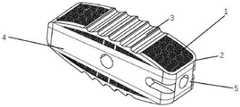
图1是本发明的生物仿生型椎间融合器的结构示意图。FIG. 1 is a schematic structural diagram of the biomimetic intervertebral cage of the present invention.
图2是本发明的添加成骨仓后的生物仿生型椎间融合器的结构示意图。FIG. 2 is a schematic structural diagram of the biomimetic intervertebral cage after adding the osteogenic cartridge of the present invention.
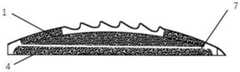
图3是本发明的多孔结构、peek注塑部件和注塑挡板的结构示意图。FIG. 3 is a schematic structural diagram of the porous structure, the peek injection-molded part and the injection-molded baffle of the present invention.
图4是本发明的类矩形的生物仿生型椎间融合器的结构示意图。FIG. 4 is a schematic structural diagram of a rectangular-like biomimetic interbody cage of the present invention.
图5是本发明的类椭圆形的生物仿生型椎间融合器的结构示意图。FIG. 5 is a schematic structural diagram of the ellipse-like biomimetic intervertebral cage of the present invention.
图6是本发明的生物仿生型椎间融合器的植入方式示意图。FIG. 6 is a schematic diagram of the implantation method of the biomimetic intervertebral cage of the present invention.
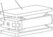
图7是本发明的撑开部件的结构示意图。FIG. 7 is a schematic view of the structure of the spreading member of the present invention.
图8是本发明的撑开部件的结构侧视图。Fig. 8 is a side view of the structure of the expansion member of the present invention.
图9是本发明的撑开部件的部分结构示意图。FIG. 9 is a partial structural schematic diagram of the spreading member of the present invention.
图10是本发明的撑开部件和合金部件的结构示意图。FIG. 10 is a schematic structural diagram of the spreader part and the alloy part of the present invention.
图11是本发明的生物仿生型椎间融合器制备方法的步骤流程图。Fig. 11 is a flow chart of the steps of the preparation method of the biomimetic intervertebral cage of the present invention.
图12是本发明的生物仿生型椎间融合器制备方法的注塑腔和注塑模具的结构示意图。12 is a schematic structural diagram of an injection cavity and an injection mold of the method for preparing a biomimetic intervertebral cage of the present invention.
图13是本发明的生物仿生型椎间融合器与注塑模具的结构示意图。13 is a schematic structural diagram of the biomimetic intervertebral cage and the injection mold of the present invention.
1-多孔结构、2-支撑框架、3-防脱齿、4-peek注塑部件、5-夹持端口、6-成骨仓、7-注塑挡板、8-peek注塑平台件、9-滑块、10-螺杆、11-中部peek稳定件。1-Porous structure, 2-Support frame, 3-Anti-drop teeth, 4-Peek injection parts, 5-Clamping ports, 6-Ossification cartridge, 7-Injection baffles, 8-Peek injection platform parts, 9-Slide Block, 10-Screw, 11-Central peek stabilizer.
具体实施方式Detailed ways
下面详细描述本发明的实施例,所述实施例的示例在附图中示出,其中自始至终相同或类似的标号表示相同或类似的元件或具有相同或类似功能的元件。下面通过参考附图描述的实施例是示例性的,旨在用于解释本发明,而不能理解为对本发明的限制。The following describes in detail the embodiments of the present invention, examples of which are illustrated in the accompanying drawings, wherein the same or similar reference numerals refer to the same or similar elements or elements having the same or similar functions throughout. The embodiments described below with reference to the accompanying drawings are exemplary, and are intended to explain the present invention and should not be construed as limiting the present invention.
在本发明的描述中,需要理解的是,术语“长度”、“宽度”、“上”、“下”、“前”、“后”、“左”、“右”、“竖直”、“水平”、“顶”、“底”“内”、“外”等指示的方位或位置关系为基于附图所示的方位或位置关系,仅是为了便于描述本发明和简化描述,而不是指示或暗示所指的装置或元件必须具有特定的方位、以特定的方位构造和操作,因此不能理解为对本发明的限制。此外,在本发明的描述中,“多个”的含义是两个或两个以上,除非另有明确具体的限定。In the description of the present invention, it should be understood that the terms "length", "width", "upper", "lower", "front", "rear", "left", "right", "vertical", The orientations or positional relationships indicated by "horizontal", "top", "bottom", "inside", "outside", etc. are based on the orientations or positional relationships shown in the accompanying drawings, which are only for the convenience of describing the present invention and simplifying the description, rather than Indication or implication that the referred device or element must have a particular orientation, be constructed and operate in a particular orientation, is not to be construed as a limitation of the invention. In addition, in the description of the present invention, "plurality" means two or more, unless otherwise expressly and specifically defined.
请参阅图1至图10,其中,图1是生物仿生型椎间融合器的结构示意图,图2是添加成骨仓后的生物仿生型椎间融合器的结构示意图,图3是多孔结构、peek注塑部件和注塑挡板的结构示意图,图4是类矩形的生物仿生型椎间融合器的结构示意图,图5是类椭圆形的生物仿生型椎间融合器的结构示意图,图6是的生物仿生型椎间融合器的植入方式示意图,图7是撑开部件的结构示意图,图8是撑开部件的结构侧视图,图9是撑开部件的部分结构示意图,图10是撑开部件和合金部件的结构示意图。本发明提供了一种生物仿生型椎间融合器,所述生物仿生型椎间融合器包括合金部件和peek注塑部件4,所述peek注塑部件4的上表面和下表面均设置有所述合金部件;Please refer to FIG. 1 to FIG. 10, wherein, FIG. 1 is a schematic structural diagram of a biomimetic intervertebral cage, FIG. 2 is a schematic structural diagram of a biomimetic intervertebral cage after adding an osteogenic cartridge, and FIG. 3 is a porous structure, Schematic diagram of the structure of peek injection molded parts and injection baffles, Figure 4 is a schematic diagram of the structure of a rectangular-like biomimetic intervertebral cage, Figure 5 is a schematic diagram of the structure of an elliptical biomimetic intervertebral cage, and Figure 6 is a Schematic diagram of the implantation method of the biomimetic intervertebral cage, FIG. 7 is a schematic diagram of the structure of the opening part, FIG. 8 is a side view of the structure of the opening part, FIG. 9 is a schematic diagram of the partial structure of the opening part, and FIG. Schematic diagram of the structure of components and alloy components. The present invention provides a biomimetic intervertebral cage, the biomimetic intervertebral cage includes an alloy part and a
所述合金部件包括多孔结构1、支撑框架2和防脱齿3,所述支撑框架2设置于所述peek注塑部件4的外侧壁,所述支撑框架2内填充有所述多孔结构1,所述防脱齿3与所述支撑框架2固定连接,并位于所述多孔结构1的上方。The alloy part includes a
在本实施方式中,可根据患者治疗情况,改变所述合金部件和所述peek注塑部件4的形状,所述支撑框架2设置于所述peek注塑部件4的外侧壁,从而保障有足够的承载能力,所述支撑框架2内填充有所述多孔结构1,所述多孔结构1可以提供良好的骨长入空间,帮助锥体融合,同时可以降低所述合金部件和所述peek注塑部件4的弹性模量,防止应力屏蔽造成松动和骨溶解,所述防脱齿3设置于所述多孔结构1的上方,所述防脱齿3防止所述生物仿生型椎间融合器在人体内松动,通过注塑处理,将所述合金部件和所述peek注塑部件4紧密连接,实现了解决椎间融合器的应力屏蔽问题,避免了产生沉降。In this embodiment, the shape of the alloy part and the
进一步地,所述合金部件还包括注塑挡板7,所述支撑框架2内设置有所述注塑挡板7,并位于所述防脱齿3的下方。Further, the alloy component further includes an injection-molded
在本实施方式中,所述注塑挡板7将所述多孔结构1和骨长入区域进行分隔,防止注塑时peek材料越界进入所述多孔结构1,破坏椎间融合效果。In this embodiment, the
进一步地,所述合金部件还包括成骨仓6,所述多孔结构1内设置有所述成骨仓6。Further, the alloy component further includes an
在本实施方式中,根据患者治疗部位的情况,在所述多孔结构1内设置成骨仓6,并设计所述成骨仓6的形状,往所述成骨仓6内添加碎骨,从而加快锥体融合。In the present embodiment, according to the condition of the patient's treatment site, a bone-forming
进一步地,所述peek注塑部件4上具有夹持端口5。Further, the
在本实施方式中,为方便植入所述生物仿生型椎间融合器,设置所述夹持端口5,以便移动所述生物仿生型椎间融合器的过程中,提高所述生物仿生型椎间融合器移动过程中的稳定性。In this embodiment, in order to facilitate the implantation of the biomimetic intervertebral cage, the clamping
进一步地,所述合金部件的材料为Ti6Al4V钛合金、钴铬钼合金、钽合金中一种或多种组合。Further, the material of the alloy component is one or more combinations of Ti6Al4V titanium alloy, cobalt-chromium-molybdenum alloy, and tantalum alloy.
在本实施方式中,所述合金部件的材料为Ti6Al4V钛合金、钴铬钼合金、钽合金中一种或多种组合,提高所述生物仿生型椎间融合器的使用寿命。In this embodiment, the material of the alloy component is one or more combinations of Ti6Al4V titanium alloy, cobalt-chromium-molybdenum alloy, and tantalum alloy, so as to improve the service life of the biomimetic interbody cage.
进一步地,所述生物仿生型椎间融合器还包括撑开部件,所述撑开部件包括peek注塑平台件8、两个滑块9、螺杆10和中部peek稳定件11,所述中部peek稳定件8设置于所述peek注塑部件4的外侧壁,所述中部peek稳定件11的上表面和下表面均设置有所述peek注塑平台件8,每个所述滑块9分别与所述peek注塑平台件8滑动连接,且每个所述滑块9上分别设置有所述螺杆10。Further, the biomimetic intervertebral cage also includes a spreading member, which includes a peek
在本实施方式中,通过转动所述螺杆10,所述螺杆10上分布的两个不同旋向的螺纹,通过螺纹配合带动所述滑块9移动,所述螺杆10顺时针转动时,带动所述滑块9往中心移动,所述滑块9与所述peek注塑平台件8之间有滑槽连接,增加了滑动时的稳定度,减少了应力集中,同时加强所述可撑开部件的连接性能。In this embodiment, by rotating the
请参阅图11和图13,其中,图11是生物仿生型椎间融合器制备方法的步骤流程图,图12是生物仿生型椎间融合器制备方法的注塑腔和注塑模具的结构示意图,图13是生物仿生型椎间融合器与注塑模具的结构示意图。本发明还提供了一种生物仿生型椎间融合器的制备方法,包括如下步骤:Please refer to FIG. 11 and FIG. 13 , wherein, FIG. 11 is a flow chart of the steps of a method for preparing a biomimetic intervertebral cage, and FIG. 12 is a schematic structural diagram of an injection cavity and an injection mold of the method for preparing a biomimetic intervertebral cage. 13 is a schematic diagram of the structure of the biomimetic intervertebral cage and the injection mold. The present invention also provides a preparation method of a biomimetic intervertebral cage, comprising the following steps:
S1:通过三维设计软件进行所述生物仿生型椎间融合器的三维模型的设计,并完成注塑结合区域与骨长入区域隔离的所述注塑挡板7的设计;S1: Design the three-dimensional model of the biomimetic intervertebral cage through three-dimensional design software, and complete the design of the injection-
S2:根据设计的三维数据设计注塑模具;S2: Design the injection mold according to the designed 3D data;
S3:使用3D打印技术进行所述合金部件的制造工作,对所述合金部件完成清洗喷砂预处理工艺,并将其置于模腔内部进行注塑;S3: Use 3D printing technology to manufacture the alloy parts, complete the cleaning and sandblasting pretreatment process for the alloy parts, and place them inside the mold cavity for injection molding;
S4:留出中部所述peek注塑部件4的注塑空间,热融的peek材料经注塑口进入注塑腔,对预留的注塑空间进行填充,完成对所述合金部件注塑结合区域的所述多孔结构1的填充,所述注塑挡板7阻止peek材料越界进入骨长入空间;S4: Reserve the injection molding space of the peek
S5:注塑完毕后,所述合金部件与所述peek注塑部件4紧密连接;S5: After injection molding, the alloy part is tightly connected with the peek
S6:进行脱模,完成所述生物仿生型椎间融合器的制造。S6: demoulding is performed to complete the manufacture of the biomimetic intervertebral cage.
其中,首先通过三维设计软件进行所述生物仿生型椎间融合器的三维模型的设计,并完成注塑结合区域与骨长入区域隔离的所述注塑挡板7的设计,然后根据设计的三维数据设计注塑模具,再使用3D打印技术进行所述合金部件的制造工作,对所述合金部件完成清洗喷砂预处理工艺,并将其置于模腔内部进行注塑,留出中部所述peek注塑部件4的注塑空间,热融的peek材料经注塑口进入注塑腔,对预留的注塑空间进行填充,完成对所述合金部件注塑结合区域的所述多孔结构1的填充,所述注塑挡板7阻止peek材料越界进入骨长入空间,注塑完毕后,所述合金部件与所述peek注塑部件4紧密连接,最后进行脱模,完成所述生物仿生型椎间融合器的制造,所述peek注塑平台件经过注塑生成,并完成与所述多孔结构的紧密连接,完成注塑后,对加工完成的部件进行开槽等后处理,在这之后,进行所述滑块的配合及与所述中部peek稳定件的连接,完成生物仿生型椎间融合器的组装。Among them, the 3D model of the biomimetic interbody cage is first designed by 3D design software, and the design of the
以上所揭露的仅为本发明一种较佳实施例而已,当然不能以此来限定本发明之权利范围,本领域普通技术人员可以理解实现上述实施例的全部或部分流程,并依本发明权利要求所作的等同变化,仍属于发明所涵盖的范围。The above disclosure is only a preferred embodiment of the present invention, and of course, it cannot limit the scope of rights of the present invention. Those of ordinary skill in the art can understand that all or part of the process for realizing the above-mentioned embodiment can be realized according to the rights of the present invention. The equivalent changes required to be made still belong to the scope covered by the invention.
Claims (6)
Priority Applications (1)
| Application Number | Priority Date | Filing Date | Title |
|---|---|---|---|
| CN202210821456.9ACN115089353A (en) | 2022-07-13 | 2022-07-13 | A biomimetic intervertebral cage and preparation method thereof |
Applications Claiming Priority (1)
| Application Number | Priority Date | Filing Date | Title |
|---|---|---|---|
| CN202210821456.9ACN115089353A (en) | 2022-07-13 | 2022-07-13 | A biomimetic intervertebral cage and preparation method thereof |
Publications (1)
| Publication Number | Publication Date |
|---|---|
| CN115089353Atrue CN115089353A (en) | 2022-09-23 |
Family
ID=83297090
Family Applications (1)
| Application Number | Title | Priority Date | Filing Date |
|---|---|---|---|
| CN202210821456.9APendingCN115089353A (en) | 2022-07-13 | 2022-07-13 | A biomimetic intervertebral cage and preparation method thereof |
Country Status (1)
| Country | Link |
|---|---|
| CN (1) | CN115089353A (en) |
Citations (9)
| Publication number | Priority date | Publication date | Assignee | Title |
|---|---|---|---|---|
| US20110190888A1 (en)* | 2010-02-01 | 2011-08-04 | Bertele Theodore P | Composite Interbody Device And Method of Manufacture |
| CN102512230A (en)* | 2011-12-09 | 2012-06-27 | 北京奥精医药科技有限公司 | Spinal column fusion device internally lined with reinforced ribs |
| US20140277482A1 (en)* | 2013-03-14 | 2014-09-18 | Synthes Usa, Llc | Hybrid intervertebral disc spacer device and method of manufacturing the same |
| CN105769391A (en)* | 2016-04-05 | 2016-07-20 | 广州爱锘德医疗器械有限公司 | Vertebral fusion cage |
| US20180092754A1 (en)* | 2016-10-04 | 2018-04-05 | Medyssey Co., Ltd. | Spinal complex cage |
| KR20180115478A (en)* | 2017-04-13 | 2018-10-23 | 김정성 | Spinal Cage of Porous Structure Improved Load Resistance |
| CN112274299A (en)* | 2020-11-20 | 2021-01-29 | 重庆熙科医疗科技有限公司 | Porous metal and PEEK composite implanted joint prosthesis and preparation method thereof |
| CN112494183A (en)* | 2020-11-30 | 2021-03-16 | 北京理贝尔生物工程研究所有限公司 | Intervertebral fusion device |
| CN113749830A (en)* | 2021-10-21 | 2021-12-07 | 湖南华翔增量制造股份有限公司 | 3D prints porous type interbody fusion cage |
- 2022
- 2022-07-13CNCN202210821456.9Apatent/CN115089353A/enactivePending
Patent Citations (9)
| Publication number | Priority date | Publication date | Assignee | Title |
|---|---|---|---|---|
| US20110190888A1 (en)* | 2010-02-01 | 2011-08-04 | Bertele Theodore P | Composite Interbody Device And Method of Manufacture |
| CN102512230A (en)* | 2011-12-09 | 2012-06-27 | 北京奥精医药科技有限公司 | Spinal column fusion device internally lined with reinforced ribs |
| US20140277482A1 (en)* | 2013-03-14 | 2014-09-18 | Synthes Usa, Llc | Hybrid intervertebral disc spacer device and method of manufacturing the same |
| CN105769391A (en)* | 2016-04-05 | 2016-07-20 | 广州爱锘德医疗器械有限公司 | Vertebral fusion cage |
| US20180092754A1 (en)* | 2016-10-04 | 2018-04-05 | Medyssey Co., Ltd. | Spinal complex cage |
| KR20180115478A (en)* | 2017-04-13 | 2018-10-23 | 김정성 | Spinal Cage of Porous Structure Improved Load Resistance |
| CN112274299A (en)* | 2020-11-20 | 2021-01-29 | 重庆熙科医疗科技有限公司 | Porous metal and PEEK composite implanted joint prosthesis and preparation method thereof |
| CN112494183A (en)* | 2020-11-30 | 2021-03-16 | 北京理贝尔生物工程研究所有限公司 | Intervertebral fusion device |
| CN113749830A (en)* | 2021-10-21 | 2021-12-07 | 湖南华翔增量制造股份有限公司 | 3D prints porous type interbody fusion cage |
Non-Patent Citations (1)
| Title |
|---|
| KWUN-MOOK LIM等: "Design and Biomechanical Verification of Additive Manufactured Composite Spinal Cage Composed of Porous Titanium Cover and PEEK Body", 《APPLIED SCIENCES》, vol. 9, no. 20, 11 October 2019 (2019-10-11)* |
Similar Documents
| Publication | Publication Date | Title |
|---|---|---|
| US20210346171A1 (en) | Implant with Improved Flow Characteristics | |
| RU2712032C2 (en) | Porous structure for bone implants | |
| EP0518278B1 (en) | Prosthetic implant | |
| US20190091027A1 (en) | Structure for facilitating bone attachment | |
| KR100788478B1 (en) | Bone Implants for Intervertebral Implants | |
| JP2020515350A (en) | Fluid interface system for implants | |
| US7951200B2 (en) | Vertebral implant including preformed osteoconductive insert and methods of forming | |
| CN110974488B (en) | Preparation method of Thiessen polygonal bionic artificial bone structure based on fractured bone surface | |
| CN107411855A (en) | Atlas and axis fusion of intervertebral joints device | |
| CN103068343A (en) | Surgical implant | |
| JP2016163706A (en) | Orthopaedic implant with porous structural member | |
| US8226723B2 (en) | Self-retaining artificial spinal disc, and associated methods | |
| CN106344221A (en) | Bonelike porous biomechanical bionic designed spinal fusion device and preparation method and use thereof | |
| JP6352183B2 (en) | Body made of bone substitute material and manufacturing method | |
| CN103565561B (en) | Artificial lumbar intervertebral disc | |
| US11786376B2 (en) | Particulate biomaterial containing particles having geodesic forms, method of making the same and using for filling or bone tissue substitution | |
| CN112274299A (en) | Porous metal and PEEK composite implanted joint prosthesis and preparation method thereof | |
| CN111202601A (en) | A direct implanted personalized alveolar bone repair prosthesis and preparation method thereof | |
| CN113081406A (en) | Intervertebral fusion device | |
| CN115089353A (en) | A biomimetic intervertebral cage and preparation method thereof | |
| CN114886617B (en) | Preparation method of space filling curve type porous implant and implant | |
| Dantas et al. | Subperiosteal dental implants: Past or future? A critical review on clinical trials/case reports and future directions | |
| CN111494061A (en) | Personalized mandible substitute compounded with autologous bone | |
| CN209048361U (en) | One kind is based on the molding three-dimensional bone repairing support of 3D printing | |
| CN114176845A (en) | Bionic bone graft for filling individual customized long bone defect |
Legal Events
| Date | Code | Title | Description |
|---|---|---|---|
| PB01 | Publication | ||
| PB01 | Publication | ||
| SE01 | Entry into force of request for substantive examination | ||
| SE01 | Entry into force of request for substantive examination |