CN115087606A - Capsule for beverage - Google Patents
Capsule for beverageDownload PDFInfo
- Publication number
- CN115087606A CN115087606ACN202180013647.6ACN202180013647ACN115087606ACN 115087606 ACN115087606 ACN 115087606ACN 202180013647 ACN202180013647 ACN 202180013647ACN 115087606 ACN115087606 ACN 115087606A
- Authority
- CN
- China
- Prior art keywords
- ring
- cellulose
- capsule
- bonding layer
- layer
- Prior art date
- Legal status (The legal status is an assumption and is not a legal conclusion. Google has not performed a legal analysis and makes no representation as to the accuracy of the status listed.)
- Pending
Links
Images


Classifications
- B—PERFORMING OPERATIONS; TRANSPORTING
- B65—CONVEYING; PACKING; STORING; HANDLING THIN OR FILAMENTARY MATERIAL
- B65D—CONTAINERS FOR STORAGE OR TRANSPORT OF ARTICLES OR MATERIALS, e.g. BAGS, BARRELS, BOTTLES, BOXES, CANS, CARTONS, CRATES, DRUMS, JARS, TANKS, HOPPERS, FORWARDING CONTAINERS; ACCESSORIES, CLOSURES, OR FITTINGS THEREFOR; PACKAGING ELEMENTS; PACKAGES
- B65D85/00—Containers, packaging elements or packages, specially adapted for particular articles or materials
- B65D85/70—Containers, packaging elements or packages, specially adapted for particular articles or materials for materials not otherwise provided for
- B65D85/804—Disposable containers or packages with contents which are mixed, infused or dissolved in situ, i.e. without having been previously removed from the package
- B65D85/8043—Packages adapted to allow liquid to pass through the contents
- B65D85/8064—Sealing means for the interface with the processing machine
- Y—GENERAL TAGGING OF NEW TECHNOLOGICAL DEVELOPMENTS; GENERAL TAGGING OF CROSS-SECTIONAL TECHNOLOGIES SPANNING OVER SEVERAL SECTIONS OF THE IPC; TECHNICAL SUBJECTS COVERED BY FORMER USPC CROSS-REFERENCE ART COLLECTIONS [XRACs] AND DIGESTS
- Y02—TECHNOLOGIES OR APPLICATIONS FOR MITIGATION OR ADAPTATION AGAINST CLIMATE CHANGE
- Y02W—CLIMATE CHANGE MITIGATION TECHNOLOGIES RELATED TO WASTEWATER TREATMENT OR WASTE MANAGEMENT
- Y02W90/00—Enabling technologies or technologies with a potential or indirect contribution to greenhouse gas [GHG] emissions mitigation
- Y02W90/10—Bio-packaging, e.g. packing containers made from renewable resources or bio-plastics
Landscapes
- Engineering & Computer Science (AREA)
- Mechanical Engineering (AREA)
- Apparatus For Making Beverages (AREA)
- Formation And Processing Of Food Products (AREA)
- Jellies, Jams, And Syrups (AREA)
Abstract
Description
Translated fromChinese本发明涉及一种用于饮品的胶囊,该胶囊是适于容纳待结合到流体以获得最终产品的初始产品的胶囊。The present invention relates to a capsule for beverages, which is a capsule suitable for containing an initial product to be incorporated into a fluid to obtain a final product.
特别地,本发明涉及一种单剂量一次性胶囊,该胶囊容纳初始产品,例如咖啡粉,该初始产品能够通过与加压水相互作用来制造最终产品,例如咖啡饮品。In particular, the present invention relates to a single-dose disposable capsule containing an initial product, such as coffee powder, capable of interacting with pressurized water to manufacture a final product, such as a coffee drink.
详细地说,胶囊特别被构造为在自动分配机中制备产品,例如饮品。In detail, the capsule is particularly configured to prepare a product, such as a beverage, in an automatic dispensing machine.
用于在分配机中使用的已知胶囊是一次性的单剂量容器,其包括外部外壳并且具有玻璃器皿或杯的形状。外壳通常具有基底壁和侧壁,基底壁和侧壁限定了容纳初始产品例如磨碎的咖啡或茶的腔,由初始产品获得最终产品,例如饮品。凸缘边缘从侧壁延伸并围绕腔布置在与基底壁相对的一侧上。Known capsules for use in dispensing machines are disposable single-dose containers comprising an outer shell and having the shape of a glass vessel or cup. The housing typically has a base wall and side walls that define a cavity containing an initial product, such as ground coffee or tea, from which a final product, such as a beverage, is obtained. A flange edge extends from the side wall and is disposed around the cavity on an opposite side from the base wall.
腔在其自身的口部处通过固定到凸缘边缘的覆盖元件气密地封闭,以便将初始产品密封在容器内。The cavity is hermetically closed at its own mouth by a covering element fixed to the flange edge in order to seal the initial product within the container.
胶囊可以用在分配机中,其中,胶囊可以由用户插入分配机的腔室中。在分配期间,胶囊的基底壁通过注射装置穿孔以将加压液体例如水注射到胶囊中,并且覆盖元件通过分配机的分配装置穿孔以使得最终产品能够被分配。The capsule can be used in a dispensing machine, wherein the capsule can be inserted into a chamber of the dispensing machine by a user. During dispensing, the base wall of the capsule is perforated by the injection device to inject a pressurized liquid, eg water, into the capsule, and the cover element is perforated by the dispensing device of the dispenser to enable the final product to be dispensed.
分配机的分配装置包括设有多个尖头元件的分配板,当胶囊内的流体压力增加时,尖头元件与覆盖元件接合并且在多个不同区域中对覆盖元件进行穿孔。最终产品可以通过由分配机的分配装置制成的穿孔流入完成容器。The dispensing device of the dispensing machine comprises a dispensing plate provided with a plurality of pronged elements which engage and perforate the covering element in a plurality of different areas when the fluid pressure within the capsule increases. The final product can flow into the finished container through perforations made by the dispensing device of the dispensing machine.
为了获得良好的分配结果,胶囊还包括布置在凸缘边缘处的密封元件,该密封元件被配置为与分配机,特别是与分配机的突出形状的容纳元件形成流体密封,胶囊可插入到突出形状的容纳元件中。In order to obtain a good dispensing result, the capsule also comprises a sealing element arranged at the flange edge, which is configured to form a fluid seal with the dispensing machine, in particular with the protruding-shaped receiving element of the dispensing machine, into which the capsule can be inserted shaped receiving element.
密封元件在分配机的高操作压力下防止加压液体流出,并且在使用中,被挤压在分配机的容纳元件和分配装置的分配板之间。The sealing element prevents the outflow of the pressurized liquid under the high operating pressure of the dispenser and, in use, is squeezed between the receiving element of the dispenser and the dispensing plate of the dispensing device.
专利EP1654966提供了一种带有密封元件的胶囊的例子,其中,外壳由铝制成,密封元件是由硅橡胶制成的弹性环并且固定到凸缘边缘。Patent EP1654966 provides an example of a capsule with a sealing element, wherein the outer shell is made of aluminium, the sealing element is an elastic ring made of silicone rubber and fixed to the flange edge.
使用铝作为胶囊的外壳是特别有利的,这是因为它能够使初始产品在腔内长时间保持,不透氧和不透水蒸气。然而,将弹性环放置在硅树脂外壳中需要将硅橡胶施加到凸缘边缘的装置,并且难以生产,因此如果密封元件的应用不精确,则在饮品分配过程中可能会发生不希望的水泄漏。The use of aluminium as the shell of the capsule is particularly advantageous because it enables the initial product to remain in the cavity for a long time, impermeable to oxygen and water vapour. However, placing the elastic ring in the silicone housing requires a means of applying silicone rubber to the edge of the flange and is difficult to produce, so if the application of the sealing element is not precise, unwanted water leakage may occur during beverage dispensing .
此外,虽然铝自身是可回收的,但是由铝外壳和硅橡胶密封元件形成的主体不再是可回收的,这对越来越感到需要制造完全可回收的产品以用于废物处理的目的构成了问题。Furthermore, while aluminium itself is recyclable, the body formed by the aluminium housing and the silicone rubber sealing element is no longer recyclable, which constitutes an increasing sense of the need to manufacture fully recyclable products for waste disposal purposes. problem.
为此目的,这样的胶囊在市场上变得普遍,其中,外壳可以是铝、可回收塑料材料或PLA(聚乳酸)或其他可分解材料,诸如纤维素,并且其中,密封元件可以是可分解材料环,例如它由基于纤维素的材料制成,例如纸或天然纤维,以确保胶囊具有仅可分解或完全可回收的成分。For this purpose, capsules have become common on the market, wherein the outer shell can be aluminium, recyclable plastic material or PLA (polylactic acid) or other decomposable material, such as cellulose, and wherein the sealing element can be decomposable The material ring, eg it is made of cellulose-based material, such as paper or natural fibers, to ensure that the capsule has only decomposable or fully recyclable components.
在市场上最普遍的带有铝外壳的胶囊中,凸缘边缘是平面的并且可以包括卷曲的环形端部卷边,根据现有技术,铝外壳的一个边界在其自身上折叠。环形卷边相对于凸缘边缘对称,并且朝向基底壁延伸并且在相对于基底壁的相对侧上延伸。In the most common capsules with aluminium shells on the market, the flange edges are flat and may include curled annular end beads, one border of the aluminium shell is folded upon itself according to the prior art. The annular bead is symmetrical with respect to the flange edge and extends towards the base wall and on the opposite side with respect to the base wall.
在其他材料的胶囊中,无论是PLA、可分解材料还是可回收塑料材料,凸缘边缘都可以是平面的并且端部处没有环形卷边。In capsules of other materials, whether PLA, decomposable or recyclable plastic, the flange edges can be flat and have no annular bead at the ends.
通过对密封元件不是硅橡胶而是基于纤维素的材料(例如纸和/或纸板)的胶囊进行实验性分配测试,申请人注意到可能发生有缺陷的分配操作。By conducting experimental dispensing tests on capsules in which the sealing element is not silicone rubber, but a cellulose-based material such as paper and/or cardboard, applicants have noticed that defective dispensing operations may occur.
例如,申请人已经证实可能在饮品之前仅分配水。For example, the applicant has demonstrated that it is possible to dispense only water before the drink.
这种缺陷是由于从分配机的前部和/或后部发生的水泄漏,该水被传送到旨在随后接收饮品的完成容器,以不希望的方式稀释了要获得的饮品。This drawback is due to leakage of water from the front and/or rear of the dispenser, which water is conveyed to the completion container intended to receive the beverage subsequently, diluting the beverage to be obtained in an undesirable way.
这种泄漏是由于为了制成饮品而注射的水的压力而造成的流体损失,其可能是前部损失和/或后部损失,并且可能是由于水渗入纸密封元件中,这在分配过程中损坏了密封环自身或者可能是由于密封元件从凸缘边缘部分的分离。This leakage is due to fluid loss due to the pressure of the water injected to make the beverage, which may be front and/or rear losses, and may be due to water seeping into the paper sealing element, which during dispensing Damage to the sealing ring itself or possibly due to separation of the sealing element from the flange edge portion.
为此目的,已经提出了具有纸密封元件的胶囊,例如在文献ES1226796U中,其中,密封元件在外部涂有例如一层不渗透的清漆,表现出已知的疏水活性。For this purpose, capsules with paper sealing elements have been proposed, for example in document ES1226796U, wherein the sealing elements are externally coated with eg a layer of impermeable varnish exhibiting the known hydrophobic activity.
然而,将表面清漆施加到密封元件是一项非常复杂的操作,并且产生的密封元件特别昂贵。However, the application of surface varnishes to sealing elements is a very complex operation and the resulting sealing elements are particularly expensive.
因此,形成本发明基础的技术目的是提供一种克服已知类型胶囊的缺点的胶囊。Therefore, the technical object which forms the basis of the present invention is to provide a capsule which overcomes the disadvantages of known types of capsules.
本发明的另一个目的是获得具有由纸质材料制成的密封元件的胶囊,其降低了缺陷的百分比,即由于流体泄漏导致的有缺陷的分配操作相对于所进行的总分配操作的百分比,以提高分配的饮品的质量。Another object of the invention is to obtain capsules with sealing elements made of paper material, which reduce the percentage of defects, ie the percentage of defective dispensing operations due to fluid leakage relative to the total dispensing operations performed, to improve the quality of the beverage dispensed.
本发明的另一个目的是获得一种制造简单且成本适中的胶囊,该胶囊具有由纸质材料制成的密封元件,其允许良好的饮品提取质量并且同时其制造简单并且便宜。Another object of the present invention is to obtain a capsule which is simple and inexpensive to manufacture, having a sealing element made of paper material, which allows a good quality of beverage extraction and at the same time is simple and inexpensive to manufacture.
这些目的通过根据本发明的包括在一个或多个所附权利要求中阐述的技术特征的胶囊来实现。These objects are achieved by a capsule according to the invention comprising the technical features set forth in one or more of the appended claims.
本发明的其他特征和优点将从以下对如附图中所示的胶囊的优选但非排他性实施方式的指示性且因此非限制性的描述变得更清楚,在附图中:Other features and advantages of the present invention will become apparent from the following indicative and therefore non-limiting description of preferred but non-exclusive embodiments of the capsule as shown in the accompanying drawings, in which:
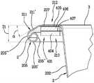
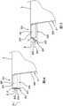
图1是包括具有凸缘边缘的外壳的胶囊在该胶囊自身的基底壁所在侧上的立体图,其中,为了清楚起见,固定到凸缘边缘的覆盖元件示出为从外壳分离;Figure 1 is a perspective view of a capsule comprising a shell with a flanged edge on the side of the capsule itself where the base wall is, wherein, for clarity, a cover element fixed to the flanged edge is shown detached from the shell;
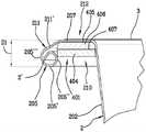
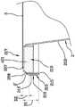
图2示出了图1的胶囊的在与基底壁所在侧相反的一侧的立体截面图;Figure 2 shows a perspective cross-sectional view of the capsule of Figure 1 on the side opposite the side where the base wall is located;
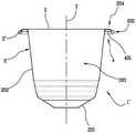
图3示出了图1的胶囊的截面图;Figure 3 shows a cross-sectional view of the capsule of Figure 1;
图4示出了图3的截面图的放大图,其中,详细示出了凸缘边缘,该凸缘边缘包括第一部分、平面的第二部分和密封元件,第一部分包括布置在凸缘边缘的端部处的环形卷边并且其中外壳的边界是卷曲的,密封元件制成为环并且在面向基底壁的一侧上与凸缘边缘的第二部分相关联;Figure 4 shows an enlarged view of the sectional view of Figure 3, wherein the flange edge is shown in detail, the flange edge comprising a first part, a planar second part and a sealing element, the first part comprising a an annular bead at the end and wherein the boundary of the housing is crimped, the sealing element made as a ring and associated with the second part of the flange edge on the side facing the base wall;
图5示出了根据本发明的图1的胶囊的一种版本的凸缘边缘的放大图,其中,环由分层结构制成并且固定到凸缘边缘,该分层结构包括叠置并固定在一起的外层和内层;Fig. 5 shows an enlarged view of the flange edge of a version of the capsule of Fig. 1 according to the present invention, wherein the ring is made of a layered structure and secured to the flange edge, the layered structure comprising stacking and securing outer and inner layers together;
图6示出了图1的胶囊的不同版本的凸缘边缘的放大图,其中,通过根据本发明的图5的分层结构制成的环邻接在胶囊的环形卷边和侧壁上;Fig. 6 shows an enlarged view of the flange edge of a different version of the capsule of Fig. 1, wherein the ring made by the layered structure of Fig. 5 according to the present invention abuts on the annular bead and side wall of the capsule;
图7示出了图1的胶囊的另一个不同版本的凸缘边缘的放大图,其中,密封元件包括在面向基底壁的一侧上与凸缘边缘相关联的环和布置在凸缘边缘的相对侧上并且面向环的另一环;Fig. 7 shows an enlarged view of the flange edge of another different version of the capsule of Fig. 1, wherein the sealing element comprises a ring associated with the flange edge on the side facing the base wall and a ring arranged on the flange edge the other ring on the opposite side and facing the ring;
图8示出了图1的胶囊的变型的截面图,该胶囊与图1的胶囊的不同之处在于其所包括的凸缘边缘,其中,连接部分插置在第一部分和第二部分之间;Fig. 8 shows a cross-sectional view of a variant of the capsule of Fig. 1 which differs from the capsule of Fig. 1 by the flanged edge it comprises, wherein the connecting portion is interposed between the first portion and the second portion ;
图9是图8的放大截面图;9 is an enlarged cross-sectional view of FIG. 8;
图10示出了根据本发明的图8的胶囊的一种版本的凸缘边缘的放大图,其中,环通过图5和图6的分层结构制成;Fig. 10 shows an enlarged view of the flange edge of a version of the capsule of Fig. 8 according to the present invention, wherein the ring is made from the layered structure of Figs. 5 and 6;
图11示出了根据本发明的图8的胶囊的不同版本的凸缘边缘的放大图,其中,环邻接在连接部分和环形卷边上;Fig. 11 shows an enlarged view of the flange edge of a different version of the capsule of Fig. 8 according to the present invention, wherein the ring abuts on the connecting portion and the annular bead;
图12示出了图8的胶囊的另一个不同版本的凸缘边缘的放大图,其中,密封元件包括在面向基底壁的一侧上与凸缘边缘相关联的环以及布置在凸缘边缘的相对侧上并且面向环的另一环;Figure 12 shows an enlarged view of the flanged edge of another different version of the capsule of Figure 8, wherein the sealing element comprises a ring associated with the flanged edge on the side facing the base wall and a ring arranged on the flanged edge the other ring on the opposite side and facing the ring;
图13示出了图8的胶囊的另一个版本的凸缘边缘的放大图,其中,环具有外部弯曲区域,该外部弯曲区域从内部平面区域延伸,邻接连接部分和环形卷边;Fig. 13 shows an enlarged view of the flange edge of another version of the capsule of Fig. 8, wherein the ring has an outer curved region extending from the inner planar region adjoining the connecting portion and the annular bead;
图14示出了图1的胶囊的另一个变型的凸缘边缘的放大图,该胶囊与图1的胶囊的不同之处在于凸缘边缘所包括的环形卷边,其中,外壳的边界被折叠并且变平,第一部分是平面的并且与第二部分形成等于90°的角度;Figure 14 shows an enlarged view of the flanged edge of another variant of the capsule of Figure 1 , which differs from the capsule of Figure 1 in that the flanged edge comprises an annular bead, wherein the boundary of the shell is folded and flattened, the first part is planar and forms an angle with the second part equal to 90°;
图15示出了图14的胶囊的不同版本的凸缘边缘的放大图,其中,第一部分与第二部分形成锐角;Figure 15 shows an enlarged view of the flange edge of a different version of the capsule of Figure 14, wherein the first part forms an acute angle with the second part;
图16示出了图14的胶囊的不同变型的凸缘边缘的放大图,其包括在第一部分和第二部分之间的连接部分,并且与图8的胶囊的不同之处在于凸缘边缘所包括的环形卷边,其中,外壳的边界被折叠并且变平,第一部分是平面的并且与连接部分形成第一突变部,连接部分与第二部分形成第二突变部。Figure 16 shows an enlarged view of the flange edge of a different variant of the capsule of Figure 14, which includes a connecting portion between the first part and the second part, and differs from the capsule of Figure 8 in that the flange edge is An annular bead is included, wherein the boundary of the housing is folded and flattened, the first portion is planar and forms a first abrupt change with the connecting portion, which forms a second abrupt change with the second portion.
在以下描述中,相同的元件在各个图中用相同的附图标记表示。还规定,除非明确说明差异,否则相同的元件被认为适用于所有不同的变型。In the following description, the same elements are denoted by the same reference numerals in the various figures. It is also stated that the same elements are considered to apply to all different variations unless the differences are explicitly stated.
参考图1至图7,标号1表示根据本发明的胶囊,其可用于未示出的分配机中。更准确地说,胶囊1可插入分配机的分配室(未示出)中。Referring to Figures 1 to 7,
胶囊1包括外壳2,该外壳具有纵向延伸的轴线Z,图3所示,例如对称轴线。The
如以下将更详细地看到的,外壳2优选地由铝制成,例如通过拉伸。As will be seen in more detail below, the
外壳2可以替代地由可分解材料制成,例如PLA(聚乳酸),或由基于纤维素的材料制成,诸如纸,或者甚至由可回收或回收的塑料材料制成(使得其可以随着时间的推移多次回收)。The
外壳2大体上呈截锥形,即成形为玻璃器皿或杯。外壳2包括基底壁201和侧壁202,从而限定如图2和图3所示的敞开的腔203,外壳还包括从侧壁202延伸的凸缘边缘212。The
详细地,侧壁202从基底壁201散开直至端部,凸缘边缘212从该端部开始大体上径向地延伸。In detail, the
腔203适于容纳待结合到流体(未示出)以获得最终产品(未示出)的初始产品(未示出)。流体优选地是热的或冷的加压液体,在注入流体以获得最终产品的步骤中被引入腔203中。The
如前所述,初始产品是例如可溶的、冷冻干燥的、脱水的、浓缩的、可渗透的、冻干的、粉末状的食品产品,例如咖啡;可替代地,初始产品可以是例如叶类食品,例如茶。流体优选地是水,其是热的和加压的,这使得能够获得饮品,例如咖啡、大麦茶、茶或草本饮料。As before, the starting product is, for example, a soluble, freeze-dried, dehydrated, concentrated, permeable, freeze-dried, powdered food product, such as coffee; alternatively, the starting product can be, for example, a leaf food, such as tea. The fluid is preferably water, which is hot and pressurized, making it possible to obtain beverages such as coffee, barley tea, tea or herbal beverages.
凸缘边缘212可以包括环形卷边205,其布置在凸缘边缘212自身的外部端部处。The
外壳2的边界2’实际上可以折叠在环形卷边205中,从而使其位于卷边205自身内部。The border 2' of the
环形卷边205通常存在于具有铝外壳2的胶囊中。如果外壳由另一种材料(例如PLA、可分解材料或可回收塑料材料)制成,则由于外壳的边界2’不能折叠,因此凸缘边缘通常是平面的。The
需说明的是,在描述的其余部分中,将参考设置有环形卷边的铝外壳2,然而本发明同样适用于具有由上述其他材料之一制成的外壳2的胶囊而不失一般性。It is noted that, in the remainder of the description, reference will be made to an
胶囊1包括固定到凸缘边缘212以封闭腔203的覆盖元件3。覆盖元件3通过热量或超声焊接或胶合与基底壁201相对地固定到凸缘边缘212。The
覆盖元件3能通过分配机(dispensing machine,调剂机)的分配装置穿孔,从而最终产品可以通过覆盖元件3分配。The
密封元件4与凸缘边缘212相关联,以与分配机形成流体密封,例如与分配机的容纳元件形成流体密封,容纳元件成形为突出部。The sealing
密封元件4包括布置在基底壁201的一侧上的环形本体401,该环形本体由基于纤维素的材料制成,因此被制成纸环或纸板环,或天然纤维环或由包括这些材料的组合的成分制成的环。The sealing
随后,为了简单起见,但不限制范围,环401将被引用为用例如纸和/或纸板的基于纤维素的材料制成。Subsequently, for the sake of simplicity, but not to limit the scope, the
由于密封元件4包括基于纤维素的环401,因此密封元件4易于制造并且还使胶囊1完全可回收。Since the sealing
凸缘边缘212包括第一部分211和第二部分207,第一部分包括环形卷边205,第二部分与侧壁202连续。The
第二部分207是环形的并且位于第一平面上。The
第一部分211包含在通过第一平面限定并且面向基底壁201的半空间中,并且在平行于轴线Z的方向上朝向基底壁201延伸直到环形卷边205的自由边缘205’。The
换言之,环形卷边205的自由边缘205’是环形卷边205的最靠近基底壁201的端部。In other words, the free edge 205' of the
由于环形卷边205代表凸缘边缘212的外部端部,因此自由边缘205’也代表第一部分211最靠近基底壁201的端部。Since the
如图1至图7所示,第一部分211被限定为不突变地从外壳2的边界2’通过环形卷边205直到第二部分207。As shown in Figs. 1 to 7, the
表述“不突变”是指从外壳2的边界2’开始,第一部分211是没有角度的,即其相连的区段之间是没有角度的曲面。The expression "non-abrupt" means that, starting from the
因此,在第一部分211和面向第一部分211的侧壁202之间,可以限定凹部210,环401容纳在该凹部中,环形卷边205的自由边缘205’与第一平面相距第一距离D1,该第一距离大于或等于环401的厚度,使得凹部210可以完全容纳环401。Thus, between the
第一部分211和侧壁202之间限定的凹部210是凹形的,并且具有通过第二部分207限定的底部。The
环401可以容纳在第一部分211的整体尺寸内直至第一距离D1内的环形卷边205。The
换言之,第一部分211在侧壁202的相对侧上限定凹部210直至自由边缘205’,并且由于环401的厚度小于或等于第一距离D1,因此自由边缘205’相对于环401突出或对准。In other words, the
如将看到的,这使得能够在分配之后获得与分配机的有效分离。As will be seen, this enables an efficient separation from the dispenser to be obtained after dispensing.
如前面已经公开的,分配板设置有多个尖头元件(未示出),在分配期间,当胶囊内的流体压力增加时,尖头元件与覆盖元件3接合并且在多个不同区域中穿孔。As already disclosed before, the dispensing plate is provided with a plurality of pointed elements (not shown) which, during dispensing, when the fluid pressure inside the capsule increases, engage with the
事实上,申请人能够通过实验验证对由于胶囊1在分配结束时掉落而引起的缺陷的显著改善。In fact, the applicant was able to verify experimentally a significant improvement in the defects caused by the
事实上,凹部210能够在内部容纳环401,因此可以避免纸和分配机的排出引导件(未示出)之间的可能妨碍胶囊1正确分离的摩擦。In fact, the
自由边缘205’延伸超过环401的厚度或与其对准,因此凹部210完全容纳环401。胶囊1可以显著减少与分配机自动分离相关的缺陷,从而设法将它们归零。The free edge 205' extends beyond or is aligned with the thickness of the
然而,应该注意的是,第一部分211包括倾斜壁211’,该倾斜壁在一侧上不突变地结合到环形卷边205,而在另一侧上突变地结合到第一部分211。It should be noted, however, that the
第一部分211,具体而言是倾斜壁211’,与第二部分207形成角度α,因此限定了第二部分207和倾斜壁211’之间的突变。The
根据未示出的版本,如果胶囊由另一种材料(可分解材料、PLA或可回收或回收塑料)制成,则没有环形卷边205的第一部分211包含在面向基底壁201的半空间中,以便能够完全容纳环401,从而与第二部分207形成突变仍然可以是有效的。According to a version not shown, if the capsule is made of another material (decomposable material, PLA or recyclable or recycled plastic), the
如果我们现在考虑第一距离D1,可以注意到,该第一距离D1介于0.4mm和2.20mm之间,还更优选地介于0.90mm和1.90mm之间,还更优选地等于1.60mm。If we now consider the first distance D1, it can be noted that this first distance D1 is between 0.4 mm and 2.20 mm, still more preferably between 0.90 mm and 1.90 mm, still more preferably equal to 1.60 mm.
根据可替代版本,第一距离可以例如等于2.10mm。According to an alternative version, the first distance may eg be equal to 2.10 mm.
如图1至图7所示,环形卷边205是卷曲的并且在内部边缘205”和外部边缘205”’之间径向延伸,最大直径为宽度R,其可以介于0.4mm至1.5mm的范围内,优选地等于1.1mm。As shown in Figures 1-7, the
如果环形卷边205的直径为0.4mm,则外壳的边缘2’几乎自身折叠并且卷曲从0.8mm的直径到1.5mm的直径,环形卷边205呈圆形形状,如图1至图13所示。If the diameter of the
除了1.1mm的直径之外,其他优选的直径也是可能的,例如0.9mm、1.0mm、1.2mm或1.3mm。Besides the diameter of 1.1 mm, other preferred diameters are possible, eg 0.9 mm, 1.0 mm, 1.2 mm or 1.3 mm.
环形卷边205可以在第一平面中朝向基底壁201延伸,使得自由边缘205’被设置在至少等于卷曲的环形卷边205的最小直径的第一距离D1处。The
然而,为了使自由边缘205’延伸超过环401的厚度,优选地,环形卷边205朝向基底壁201移位,使得第一距离D1大于环形卷边205自身的最大直径。However, in order for the free edge 205' to extend beyond the thickness of the
例如,如果卷曲的环形卷边205具有等于1.1mm的直径,则自由边缘205’可以有利地设置在等于1.6mm的第一距离D1处,即,考虑到倾斜壁211’的尺寸和倾斜度,相对于环形卷边205的直径移位0.5mm。For example, if the curled
可替代地,根据胶囊的不同版本,如果卷曲的环形卷边205具有等于1.1mm的直径并且自由边缘205’可以设置在等于2.1mm的第一距离D1处,则其可以相对于环形卷边205的直径进一步移位1.0mm。Alternatively, depending on the different versions of the capsule, the curled
第一部分211径向地包含在环形卷边205的内部边缘205”和外部边缘205”’之间。The
事实上,边界2’折叠在环形卷边205中并且不突变地延伸通过倾斜壁211’直至第二部分207。In fact, the border 2' is folded in the
凸缘边缘212的第一部分211中不存在突变,该第一部分包含在面向基底壁201的半空间中,第一部分211的倾斜壁211’和第二部分207之间存在突变,以及自由边缘205’优选地相对于环形卷边205的直径朝向基底壁201移位的事实使得当与环401一起被夹在容纳元件与分配机的分配板之间时,凸缘边缘212自身更容易适应,并且与分配机协作以形成流体密封。There is no abrupt change in the
此外,可以以简单的方式在半空间中限定凹部210。Furthermore, the
第一部分211成形为最初围绕边界2’卷绕,限定环形卷边205,随后逐渐远离环形卷边205延伸直到第二部分207。The
第一部分211因此成形为螺旋形,其从边界2’开始首先围绕该边界卷绕,限定环形卷边205,并且随后逐渐远离环形卷边205延伸通过倾斜壁211’直到第二部分207。The
可以注意到,如果环形卷边205是卷曲的或圆形的并且第一部分211不突变地延伸,则用户可以完全安全地处理铝胶囊,因为没有可能伤害用户的尖部。事实上,不仅外壳的边缘2’折叠在环形卷边205内,而且也没有可能会使用户烦恼的边缘。It can be noted that if the
产生倾斜壁211’的倾斜度的角度α可以介于10°和90°之间,优选地介于14°和65°之间,还更优选地介于20°和45°之间,优选地等于25°。可替代地,角度α也可以优选地等于38°。事实上,优选的是,倾斜壁211’与基底壁207形成锐角,使得环形卷边205朝向基底壁201移位,同时第一部分211不突变地延伸通过倾斜壁211’。The angle α that produces the inclination of the inclined wall 211' may be between 10° and 90°, preferably between 14° and 65°, still more preferably between 20° and 45°, preferably is equal to 25°. Alternatively, the angle α may also preferably be equal to 38°. In fact, it is preferred that the inclined wall 211' forms an acute angle with the
关于环401的位置,其至少在旨在与分配机进行流体密封的区域中与凸缘边缘212相关联,即,在分配期间分配机的突出形状的容纳元件与其相接合的区域中。Regarding the position of the
这适于考虑根据本发明的图1至图7以及图14和图15的胶囊1并且适于考虑将在下面描述并且在图8至图13和图16中示出的胶囊1’。This applies to considering the
环401可以包括外部区域402,如图4所示,其延伸至与第一部分211邻接。
换言之,相对于环401的厚度,环401的径向延伸程度可以诸如邻接第一部分211,更准确地说是邻接环形卷边205的内部边缘205”,如在图4和图6中所示。In other words, relative to the thickness of the
环401还可以包括内部区域403,外部区域402从该内部区域延伸,如图4所示,该内部区域可以延伸直到其邻接胶囊2的侧壁202,而不管外部区域402是否可以邻接或不邻接第一部分211。The
例如,如果环401约1mm宽并且从侧壁202开始延伸,则无论如何都确保了与分配机的容纳元件的流体密封。For example, if the
然而,环401也可以仅与第二部分207相关联,而无需邻接第一部分211和/或侧壁202。However, the
在变型中,环401可以是L形的,以至少部分地遵循凸缘边缘212和侧壁202两者。In variations,
关于制成环401的方式,需说明的是,这适用于图1至图16中所示的胶囊的所有变型或版本。Regarding the way in which the
环401可以包括旨在接触分配机的单层基于纤维素的材料。层可以例如由纸或纸板制成,克重介于250g/m2和900g/m2之间,优选地介于300g/m2和750g/m2之间,优选地等于350g/m2和700g/m2。
术语克重是指纸和/或纸板的密度值,其表示为以克/平方米为单位的值。The term grammage refers to the density value of paper and/or board, expressed as a value in grams per square meter.
尽管纸和/或纸板的厚度通常取决于所使用的克重,但纸和/或纸板的厚度可以根据不同的因素而变化,例如在纸的生产过程中执行的加工类型和/或纸板或其中存在的木纤维的数量。Although the thickness of the paper and/or paperboard generally depends on the grammage used, the thickness of the paper and/or paperboard can vary depending on various factors, such as the type of processing performed during the production of the paper and/or the paperboard or the like The amount of wood fibers present.
事实上,对于相同的克重,可以存在具有设定厚度的高密度纸和/或纸板以及具有大于设定厚度的厚度的低密度纸和/或纸板。In fact, for the same grammage, there may be high density paper and/or board with a set thickness and low density paper and/or board with a thickness greater than the set thickness.
由于这个原因,尽管用于制造纸环的优选克重介于如上所述的克重范围内,但是,因为所进行的实验测试基于环401的厚度,所以环401的厚度也将在下面指出。For this reason, although the preferred grammage for making paper rings is within the grammage range described above, since the experimental tests performed were based on the thickness of the
环401可以包括分层结构,该分层结构包括基于纤维素的至少一个外层404并包括结合层405,该结合层被构造为使得分层结构能够结合凸缘边缘212,即结合到第二部分207。The
结合层405是可通过热激活的粘合材料层。
换言之,制成密封元件4的纸或纸板环401可以由单层纸和/或纸板层制成,如图2至图4和图7所示,并且通过干涉或保持通过结合层405附加地固定到铝凸缘边缘的第二部分207。In other words, the paper or
如图5和图6所示,根据本发明,环401可以由多个层404、406相互叠置而成的分层结构制成,其中,存在结合层405以用于联接到环401的凸缘边缘212,此外,另一个结合层407插置在彼此叠置的两个基于纤维素的层之间。As shown in FIGS. 5 and 6 , according to the present invention, the
分层结构可以包括:基于纤维素的外层404,向外布置成与分配机接触;结合层405,构造为使分层结构能够结合到凸缘边缘212;内层406,由基于纤维素的材料制成;以及另一结合层407,其将外层404和内层406结合在一起。内层406通过结合层405结合到凸缘边缘212。The layered structure may include: a cellulose-based
例如,环401可以至少用两个基于纤维素的层制成,但是,据此规定,分层结构也可以包括多于两个的多个基于纤维素的层。For example, the
分层结构可以具有彼此叠置并且与另一结合层407交替的多个基于纤维素的层404、406,并且可以具有用于结合到凸缘边缘212的结合层405以及用于接触分配机的基于纤维素的材料的外层404。The layered structure may have multiple cellulose-based
可选地,根据未示出的变型,外层404可以是L形的,以至少部分地遵循凸缘边缘212和侧壁202两者。Alternatively, according to a variant not shown, the
申请人已经验证,结合层405的存在,以及因此环401固定到凸缘边缘212的事实,避免了在注射加压液体期间在分配期间环401可能分离的可能性。Applicants have verified that the presence of the
尤其是,在两个基于纤维素的层404、406之间存在另一结合层407并且具有相同的其他参数来限定环401(具有相同的厚度和/或克重和/或成分)允许进一步改善相对于由例如单个基于纤维素的层和用于固定到凸缘边缘212的结合层制成的环401的流体损失。In particular, the presence of another
如前所述,术语“流体损失”是指由于密封元件4和分配机之间的流体密封缺陷导致的水从分配机的前部和/或后部泄漏。As previously mentioned, the term "fluid loss" refers to leakage of water from the front and/or rear of the dispenser due to a defective fluid seal between the sealing
结合层405可以由粘合剂材料或例如聚乙烯或聚烯烃或聚乳酸(PLA)的材料制成,当其通过热量施加到第二部分207时,其变得有粘性并且将单个层(如果环由单层基于纤维素的材料制成)或内层406(在分层结构的情况下)结合到第二部分207。The
同样的考虑也适用于另一结合层407,其被构造为将基于纤维素的外层404和基于纤维素的内层406结合在一起,该另一结合层是可通过热激活的粘合材料层。The same considerations apply to another
结合层405和另一结合层407也可以由热胶制成,该热胶在其被具有热量的加热装置激活时起作用,加热装置例如设置有具有电阻的加热元件的装置。The
结合层405以及另一结合层407也可以通过具有超声波焊接的加热装置来激活。The
根据未示出的一种变型,凸缘边缘212、优选地整个铝外壳2可以可选地在外部涂覆清漆,该清漆可以是透明的或有色的,其适合于当结合层405通过热量或超声软化或熔化以获得结合层405与凸缘边缘212的粘合时,与结合层405结合。According to a variant not shown, the
清漆被构造为在铝的外部涂覆,同时如果清漆是有色的,则使铝个性化,并且促进结合层405与外壳2的铝的粘合。清漆实际上可以结合到聚乙烯或聚乳酸,当两者都被加热(可选地,清漆也可以被加热)时,可通过热激活,以使纤维素环能够结合到涂覆铝的清漆。The varnish is configured to be applied on the outside of the aluminum, and at the same time, if the varnish is colored, personalizes the aluminum and promotes the adhesion of the
优选地,清漆被选择为与结合层405相容,从而确保永久焊接或在任何情况下适合于即使在分配期间也不使环401与凸缘边缘212分离的粘合。Preferably, the varnish is selected to be compatible with the
根据一个版本,环401通过包括外层404、内层406、结合层405和另一结合层407的分层结构制成,并且被构造为当结合层405、407尚未激活时被放置在第二部分207上。在这种情况下,结合层405、407可以同时通过热激活,以将环401结合到凸缘边缘212并且将基于纤维素的层结合在一起,从而限定固定到凸缘边缘212的紧凑而单一的环形本体401。According to one version, the
每个基于纤维素的层,即外层404和内层406,可以具有例如等于350g/m2的克重,总计700g/m2。Each of the cellulose-based layers,
即使在分层结构结合到凸缘边缘212之前,每个结合层,即结合层405或另一结合层407,可以具有例如15g/m2的克重,这对应于几微米的厚度。Even before the layered structure is bonded to the
尽管分层结构中的另一结合层407的厚度可以忽略不计,但是其使两个基于纤维素的层404和406成为一体并且有利地增加环401的强度。Although the thickness of the
事实上,另一结合层407作为水渗透从一层传播到另一层的屏障,从而保持纤维素纤维彼此牢固接触,因此使环401更难剥落。由于环401由于分层结构而更加坚固,因此其可以在最终产品的整个分配期间以有效的方式发挥其作为密封元件的功能,因此,与用单层基于纤维素的材料制成的环401相比,在具有相同的克重和/或厚度和/或成分的情况下,其可以进一步减少流体损失。In fact, the
应该注意的是,另一结合层407的厚度可以忽略不计,以至于其不参与流体密封,这意味着基于纤维素的环401的变形继续保持塑料类型的变形,这完全是由于制造环401的基于纤维素的材料,而不是另一结合层407。It should be noted that the thickness of the
由于存在其中基于纤维素的材料的层与另一结合层交替的分层结构,因此可以改善流体损失,密封元件以简单和经济的方式制造。Due to the existence of a layered structure in which layers of cellulose-based material alternate with another bonding layer, fluid losses can be improved, and the sealing element is produced in a simple and economical manner.
由于环401可以由结合在一起的至少一对基于纤维素的层404、406制成,因此其也可以根据克重和/或厚度和/或成分以适当的方式选择每层404、406。Since the
例如,被构造为布置在外部的外层404可以选择具有不同于内层406的克重和/或厚度和/或成分,使得环401具有与分配机的容纳元件的分离或流体密封但同时也具有降低的成本所需的特性。For example, the
具有多个基于纤维素的层的可能性允许选择具有不同性质的每层。例如,外层404可以选择为密度低于外层404下方的内层406的密度,以便在分配期间更好地变形并且促进流体密封,或者其可以选择与内层406(其优选地为中性白色)不同的颜色或纹理,以便能够相对于待分配的最终产品对于用户而言是可区分的。The possibility of having multiple cellulose-based layers allows the selection of each layer with different properties. For example, the
根据图7所示的一种变型,密封元件4包括由基于纤维素的材料制成的另一环408,该另一环在与凸缘边缘212相对的一侧上固定到覆盖元件3,更准确地说是在与第二部分207相对的一侧上固定到覆盖元件。According to a variant shown in FIG. 7 , the sealing
另一环408在环401上对准,以形成分层密封元件4,其中,由铝制成的平面第二部分207以及与其结合的覆盖元件3相对地布置并且彼此面对地插入在环401和另一环408之间。Another
环401与朝向基底壁201的第二部分相关联,而另一环408固定到覆盖元件3。A
关于另一环408,前面所说的适用,也就是说,另一环408也可以由基于纤维素的材料的单层404制成,通过结合层405结合到覆盖元件3,或者有利地,根据本发明,另一环408可以由包括外层404、内层406以及结合层405和另一结合层407的分层结构制成。With regard to the
另一环408可以具有不同于环401的克重和/或厚度和/或成分。Another
应该注意的是,在分配期间,另一环408有助于与分配机的流体密封,但是其也执行胶囊1和分配机之间的间隔件的功能。It should be noted that during dispensing, the
事实上,与分配机的分配板接触放置的另一环408保持凸缘边缘212,与分配板间隔开,并且使凸缘边缘212和环401朝向基底壁201移位,即,朝向分配机的突出形状的容纳元件。In fact, another
结果是,由于另一环408的存在,整体减小的厚度对于环401来说可能是足够的,从而在选择可以用于制造环401的材料方面具有经济优势。As a result, the overall reduced thickness may be sufficient for the
环401、或者如果存在另一个环408,优选地具有恒定的厚度并且是平面的。
应该注意的是,为了改善由于在分配结束时胶囊分离引起的缺陷,环401的厚度介于0.30mm和1.2mm之间,优选地介于0.55mm和1.10mm之间,还更优选地介于0.70mm和1.00mm之间,优选地等于0.90mm,这已经变得特别有利。It should be noted that in order to improve the defects due to capsule separation at the end of dispensing, the thickness of the
申请人进行的实验测试表明,通过制造其中外壳2由铝制成并且密封元件4由基于纤维素的材料制成的胶囊1,其中,第一部分211被包含在通过第二部分207标识的第一平面限定的半空间中并且朝向基底壁201延伸直至环形卷边205的自由边缘205’,从而限定凹部210,环401完全容纳在该凹部中,减少了与在分配结束时胶囊1的失败分离相关的缺陷。Experimental tests carried out by the applicant have shown that by manufacturing a
有利地,第一部分211可以成形为从边界2’通过卷曲的环形卷边205直至第二部分207不突变。Advantageously, the
环形卷边205的自由边缘205’在距第二部分207的第一距离D1处,该第一距离大于或等于环401的厚度。因此,环401完全容纳在凹部210中,并且避免在环401与分配机的弹出引导件之间的摩擦,这允许减少由于悬挂在机器中而导致的分配机中的缺陷的百分比。The free edge 205' of the
实验测试还表明,在环401的厚度等于0.45mm和环401的厚度等于0.90mm的情况下,由于自动分离导致的有缺陷的分配操作减少。Experimental tests have also shown that defective dispensing operations due to automatic separation are reduced with a thickness of the
申请人还验证,在环401的厚度介于0.55mm和1.10mm之间、还更优选地介于0.70mm和1.00mm之间、优选地等于0.90mm的情况下,由于流体损失引起的缺陷的显著改进,以及由于分离引起的缺陷的改进。The applicant has also verified that in the case where the thickness of the
随着环401的厚度增加,尽管仍然确保在分配结束时的分离,但是可以获得增强的流体密封,即,与已知的铝胶囊相比,前部和/或后部流体损失的量减少。As the thickness of the
尽管增加了厚度,但是与其中外壳包括平面铝凸缘边缘和端部环形卷边的胶囊相比由于分离失败导致的有缺陷的分配操作也减少,即使环401的厚度等于0.90mm,在外壳包括平面铝凸缘边缘和端部环形卷边的胶囊中,端部环形卷边在平行于轴线Z的方向上朝向外壳的基底壁对称地延伸并且在与平面凸缘边缘相对的一侧上。Despite the increased thickness, defective dispensing operations due to detachment failures are reduced compared to capsules in which the outer shell includes a flat aluminum flange edge and end annular beading, even though the thickness of the
有利地并且根据本发明,申请人还注意到,与单层版本相比,两个基于纤维素的层404、406在流体损失方面的改进。Advantageously and in accordance with the present invention, the applicant has also noted an improvement in fluid loss for the two cellulose-based
在使用中,胶囊1由使用者插入分配机的腔室中,为此例如通过杠杆机构打开该腔室。使用相同的机构,用户可以关闭腔室以开始分配,并且当腔室关闭时,分配机的突出形状的容纳元件可以无弹性地压缩密封元件4、即环401,以形成流体密封。在分配期间,加压流体被注入胶囊中,并且被容纳元件非弹性压缩的环401与分配机形成流体密封。In use, the
如果胶囊1除了环401之外还包括布置在与环401相对的一侧上的另一环408,则也会出现同样的情况。The same applies if the
当加压液体被注入时,最终产品的压力在胶囊1内增加,这进而使覆盖元件3朝向分配机的分配板的尖头元件变形,该尖头元件在覆盖元件3上穿孔。When the pressurized liquid is injected, the pressure of the final product increases within the
在分配结束时,用户可以通过再次致动杠杆机构来打开腔室以使胶囊1能够分离。At the end of dispensing, the user can open the chamber by actuating the lever mechanism again to enable separation of the
环形卷边205的自由边缘205’在距第二部分207的第一距离D1处,该第一距离大于或等于环401的厚度,因此环401完全容纳在凹部210中,避免了在环401和分配机的弹出引导件之间的摩擦,这使得由于悬挂在机器中而引起的分配机的缺陷的百分比能够减小。为此目的,优选地,环形卷边205朝向基底壁201移动,以确保在轴向上自由边缘205’超过环401的厚度。一旦用户打开腔室,刚刚使用的胶囊1实际上可以与容纳元件分离并且可以落入到已经使用过的胶囊的回收容器中。The
图8至图13示出了胶囊1’,其与图1至图8中所示的胶囊1的不同之处在于胶囊1’设置有凸缘边缘204,该凸缘边缘与迄今为止描述的凸缘边缘212的不同之处在于其包括不同于上述第一部分211的第一部分206。Figures 8 to 13 show a capsule 1' which differs from the
然而,前面所说的仍然适用,即,第一部分206包含在由第一平面限定并且面向基底壁201的半空间中,该第一部分在平行于轴线Z的方向上朝向基底壁201延伸直到环形卷边205的自由边缘205’,在第一部分206和面向第一部分206的侧壁202之间,限定凹部210,环401被容纳并完全包含在该凹部中,这是因为环形卷边205的自由边缘205’在距第一平面的第一距离D1处,该第一距离大于或等于环401的厚度。However, what was said before still applies, ie, the
然而,凸缘边缘204另外包括布置在第一部分206和第二部分207之间的连接部分208,第一部分206在距第一平面至少第二预定距离D2处朝向基底壁201移位,在连接部分208和侧壁202之间限定至少部分容纳环401的座209。However, the
座209是凹形的并且具有通过第二部分207限定的相应底部。The
凹部210被限定在第一部分206和侧壁202之间并且其自身由对应于第二部分207的相应底部界定,因此容纳座209。The
第一部分206朝向基底壁201移位并且形成其中至少部分地容纳环401的座209。使用该胶囊1’,不仅确保了在分配之后与分配机的有效分离,而且在流体密封方面也有重要的改进,即减少了前部和/或后部流体损失的量。The
关于流体密封,移动到第二距离D2并且使得第一部分206和位于第一平面中的第二部分207之间的水平高度变化允许在连接部分208处在凸缘边缘204中产生变形,这使得当其与环401一起被夹在容纳元件和分配机的分配板之间时,凸缘边缘204自身更容易适应。With regard to fluid sealing, moving to the second distance D2 and having a change in level between the
另一方面,关于胶囊1在分配结束时的下落,因为自由边缘205’被放置在距第一平面的第一距离D1处,该第一距离大于或等于环401厚度,所以凹部210可以将环401完全容纳在其自身内部仍然适用。On the other hand, with regard to the drop of the
自身内部可部分容纳环401的座209可以进一步促进环401的容纳,从而进一步防止纸与分配机的弹出引导件(未示出)之间的任何摩擦,这可防止胶囊1不恰当地分离。The
因此,同样在这种变型中,凸缘边缘204具有移位的环形卷边205,并且纸环可以至少部分地容纳在座209中。胶囊1可以显著地减小与从分配机自动分离相关的缺陷,并且减少与流体损失相关的缺陷。Thus, also in this variant, the
应该注意的是,第一部分206包含在面向基底壁201的半空间中,其通过位于所述第二预定距离D2处的第二平面限定。It should be noted that the
换言之,第二距离D2是第一部分206移位的距离,第一部分也包括环形卷边205。In other words, the second distance D2 is the distance by which the
应该注意的是,第一部分206包括环形部分206’,该环形部分与连接部分208相连并且是平面的,环形部分206’位于第二平面上。It should be noted that the
因此,距离D2在平行于轴线Z的方向上在环形且平坦的凸缘边缘204的第二部分207与第一部分206的环形部分206’之间是可测量的。Thus, the distance D2 is measurable in a direction parallel to the axis Z between the
再次应用前面所说的,即,第一部分206被包括在卷曲的环形卷边205的内部边缘205’和外部边缘205”之间,并且第一部分206通过卷曲的环形卷边205由外壳2的边界2’不突变地限定直至平面环形壁206’。因此,第一部分206成形为螺旋形,其从边界2’开始首先围绕边界2’卷绕,从而限定环形卷边205,并且随后通过平面环形壁206’直到连接部分208将其保持在靠近环形卷边205的位置。Again applying what was said before, that is, the
与胶囊1的第一部分211不同(该第一部分从外壳2的边界2’不突变地延伸直至第一部分206),在胶囊1’的第一部分206和连接部分208之间存在第一斜率变化并且在连接部分208和第二部分207之间存在第二斜率变化。换言之,虽然在胶囊1的凸缘边缘212中,在第一部分211和第二部分207之间、在第一部分211和第二部分207之间的结合处存在单个突变,在胶囊1’的凸缘边缘204中,在第一部分206和连接部分208之间存在第一突变部(限定第一角度),并且在连接部分208和第二部分207之间存在第二突变部(限定第二角度)。Unlike the
根据未示出的另一个版本,明确指出如果胶囊由另一种材料(可分解材料、PLA、或可回收或回收塑料)制成,则尽管缺少环形卷边205,但是凸缘边缘204可以具有这种形状仍然适用,由此第一部分206被包含在面向基底壁201的半空间中;该其他版本的凸缘边缘204也可以具有第一部分206,其中,存在平面环形壁206’,在第一部分206和连接部分208之间存在第一突变部,并且在连接部分208和第二部分207之间存在第二突变部。According to another version not shown, it is expressly stated that if the capsule is made of another material (decomposable material, PLA, or recyclable or recycled plastic), the
尽管之前所说的仍然适用于第一距离D1,其允许在平行于轴线Z的方向上环401的厚度完全容纳在环形卷边205的自由边缘205’内的凹部210中,明确指出第二距离D2可以介于0.10mm和0.90mm之间,还更优选地介于0.20mm和0.60mm之间,还更优选地等于0.30。While what was said before still applies to the first distance D1, which allows the thickness of the
第二预定距离D2也可以等于0.50mm。The second predetermined distance D2 may also be equal to 0.50 mm.
考虑环形卷边205在平行于轴线Z的方向上的例如等于1.30mm的尺寸并且考虑等于0.30mm的第二距离D2,可以注意到,由此,环形卷边205的自由边缘205’朝向基底壁201延伸直至距第一平面等于1.60mm的距离D1。Considering the dimension of the
关于第二距离D2以及关于环401的厚度,可以观察到环401可以在平行于轴线Z的方向上完全容纳在座209内,或者可以从其突出并被完全包含在凹部210中。With regard to the second distance D2 and with regard to the thickness of the
换言之,由于第二部分206朝向基底壁201移位,环形卷边205有助于进一步横向界定凹部210,并且与连接部分208一起限定凹部210的在面向胶囊的侧壁202的相对侧上的相应外壁。In other words, as the
使用以上作为示例提供的值,凹部210在外部通过连接部分208和/或通过达到1.60mm的环形卷边205限定。Using the values provided above as examples, the
连接部分208可以具有如图8至图13所示的阶梯式截锥构造或弯曲构造,例如具有斜率变化(未示出)。The connecting
换言之,连接部分208可以被成形为连接第一部分206和第二部分207的倾斜平面或作为其中存在曲率变化的表面。In other words, the connecting
关于环401和凸缘边缘204之间的关联,前面参照凸缘边缘212所说的适用,明确指出环401的外部区域402可以延伸直至邻接第一部分206和/或连接部分208。With regard to the association between
例如,如图11和图13所示,相对于环401的厚度,外部区域402也可以邻接在环形卷边205上,特别是其可以邻接在环形卷边205的内部边缘205”上,并且可选地朝向基底壁201弯曲,如图13所示。For example, as shown in Figures 11 and 13, relative to the thickness of the
在未示出的变型中,环401可以是L形的以至少部分地遵循凸缘边缘204和侧壁202的事实仍然有效。In a variant not shown, the fact that the
然而,如已经说过的,环401可以仅与第二部分207相关联,而无需邻接第一部分206和/或连接部分208和/或侧壁202,因为这足以使得其与凸缘边缘204在分配期间在与分配机的突出形状的容纳元件接合的区域中相关联。However, as already said, the
环401可以通过上述结合层结合到凸缘边缘204、更准确地说是第二部分207的事实仍然有效。The fact that the
关于制造环401的方式,根据本发明,明确指出先前关于图1至图7的胶囊1所描述的内容也可以应用而不限于一般性的图8至图13的胶囊1’。With regard to the manner in which the
环401可以包括上述分层结构,其中,例如存在外层404和结合层405以及内层406和另一结合层407,如图10和图11所示。
同样,可选地根据未示出的变型,外层404可以是L形的,以至少部分地遵循凸缘边缘204和侧壁202二者。Also, optionally according to a variant not shown, the
每个基于纤维素的层、即外层404和另一层406,可以具有上面指出的克重和厚度,其可以关于克重和/或厚度和/或成分以适当的方式选择,以确保流体密封和与分配机的容纳元件的分离以及降低成本所需的特性。Each cellulose-based layer, namely
同样,对于这个版本的胶囊,由于环401固定到凸缘边缘204并且包括由两个基于纤维素的层404、406彼此叠置制成的分层结构,其中,存在结合层405和另一结合层407,已经注意到流体密封相对于由单个基于纤维素的层制成的环401的改进。Also for this version of the capsule, since the
同样,如前所述,密封元件4可以包括根据上述方法制造的另一环408,例如如图12所示,该另一环在与第二部分207相对的一侧上固定到覆盖元件3,使得另一环408和环401对准且彼此相对。Also, as previously mentioned, the sealing
在使用中,胶囊1’由用户插入分配机的腔室中,并且如前文关于胶囊1所描述的那样使用。In use, the capsule 1' is inserted into the chamber of the dispensing machine by the user and used as described above with respect to the
对于连接部分208,其中凸缘边缘204变形以将第一部分206和第二平面部分207连接在一起,该第一部分以第二距离D2朝向基底壁201移位,环401与该第二平面部分相关联,凸缘边缘204适用于分配机,因此通过环401和可选地环408与分配机实现的流体密封可以得到改善。For the connecting
在分配结束时,当腔室打开以允许胶囊1’与整个容纳环401的凹部210以及至少部分容纳环401的座209分离时,分配机的弹出引导件不接触环401,一旦使用者打开腔室,则刚刚使用的胶囊1可以分离,从而落入容器中以回收已经使用的胶囊。At the end of dispensing, the ejection guide of the dispenser does not touch the
申请人进行的实验测试表明,根据图8至13制造胶囊1’,其中,外壳2由铝制成,密封元件4由基于纤维素的材料制成,其中,第一部分206包含在通过由第二部分207标识的第一平面限定的半空间中,并朝基底壁201延伸直到环形卷边205的自由边缘205’,限定了凹部210,其中,环401被完全容纳,与胶囊1在分配结束时未能分离相关联的缺陷相对于胶囊减少,其中,外壳包括平面铝凸缘边缘和环形端部卷边,该环形端部卷边在平行于轴线Z的方向朝向外壳的基底壁对称地延伸并且在与平面凸缘边缘相对的一侧上。Experimental tests carried out by the applicant have shown that the
对在分配结束时的分离的改善也确保对于胶囊1’而言,环401的厚度介于0.30mm和1.2mm之间,优选地介于0.55mm和1.10mm之间,还更优选地介于0.70mm和1.00mm,优选地等于0.90mm。The improvement in separation at the end of dispensing also ensures that the thickness of the
然而,在可替代方案中,使用设有连接部分208的凸缘边缘204的胶囊1’进行的实验测试表明,与前部和/或后部流体损失相关的缺陷也得到进一步改善,即使环没有增加的厚度而是介于0.30mm和1.2mm之间,优选地介于0.55mm和1.10mm之间,还更优选地介于0.70mm和1.00mm之间,优选地等于0.90mm。However, in the alternative, experimental tests using the capsule 1' provided with the
应当进一步注意的是,已经有利地验证了胶囊1的形状,其中,第一部分211的形状从卷曲的环形卷边205直到第二部分207不突变,并且另外突变地结合到第二部分,并且其中,第一距离D1大于环形卷边205自身的最大直径,即胶囊1’的最大直径,其中,第一部分206可以利用第一突变部结合到连接部分208并且可以利用第二突变部从连接部分208结合到第二部分207,由于在分配结束时胶囊1、1’的未分离,不仅确保改善而且确保缺陷归零。事实上,环形卷边205的自由边缘205’限定了凹部,该凹部将环401完全容纳在其内部,并且此外,在两种类型的胶囊中,环形卷边205具有其自己的自由边缘205’,该自由边缘朝向基底壁201轴向移位,第一距离D1大于环形卷边205自身的最大直径。It should be further noted that the shape of the
在胶囊1中,环401的增加的厚度能够积极地影响由于流体损失引起的缺陷,尽管如此,在分配结束时还确保了分离。In the
在胶囊1’中,凸缘边缘204的形状随着第一部分移动到第二距离D2能够在环401的任何厚度的情况下积极影响由于流体损失引起的缺陷,确保在同时胶囊自身在分配结束时分离。In the capsule 1', the shape of the
此外,根据本发明,这里描述的任何类型的胶囊,具有两个基于纤维素的层404、406的环401积极地影响分配效率,减少流体损失。Furthermore, according to the present invention, any type of capsule described here, the
图14至16示出了根据本发明第二方面的胶囊1的变型(未示出)的凸缘边缘214。Figures 14 to 16 show the
详细地,图14和15示出了凸缘边缘214,其与图1至图7的凸缘边缘212的不同之处在于它包括平面的第一部分216和从边界2’开始折叠的环形卷边215。In detail, Figures 14 and 15 show
根据未示出的不同版本,如果胶囊由另一种材料(可分解材料、PLA、或可回收或回收塑料)制成,则凸缘边缘214可以具有使得没有折叠的环形卷边215的第一部分211包含在面对基底壁201的半空间内的形状的事实仍然可以有效。According to a different version not shown, if the capsule is made of another material (decomposable material, PLA, or recyclable or recycled plastic), the
第一部分216包括倾斜壁216’,该倾斜壁与环形卷边215共面并且与第二平面部分207形成突变。The
角度β限定在倾斜壁216’和第二部分207之间并且可以大于或等于20°并且小于或等于135°。例如,在图14中,角度β等于90°,而在图15中,角度β等于60°。The angle β is defined between the
对于包括在90°和135°之间的角度β,第一部分216朝向侧壁202倾斜,即朝向环401倾斜。For an angle β comprised between 90° and 135°, the
先前参考图1的胶囊所做的考虑是有效的,即环形卷边215具有限定凹部210的自由边缘215’,能够完全容纳环401,并且位于第一平面的第一距离D1处,由第二平面部分207限定的大于或等于环401的厚度的事实仍然有效。The considerations made previously with reference to the capsule of Figure 1 are valid, namely that the
应该注意的是,图14和图15的环形卷边215除了围绕自由边缘215’折叠外,也是平坦的。It should be noted that the
事实上,在环形卷边215中,在自由边缘215’和外壳的边界2’之间限定了第一翼片,该第一翼片被设置成与从自由边缘215’开始在第一翼片的相对侧限定的第二翼片接触。In fact, in the
例如,第二翼片从自由边缘215’延伸到倾斜壁216’。For example, the second fin extends from the free edge 215' to the
在未示出的版本中,环形卷边215也可以是V形的,这意味着第一翼片和第二翼片可以不平行并且彼此接触,但是可以在它们之间形成以自由边缘215’为顶点的角度。In a version not shown, the
关于环401的制造方式及其与凸缘边缘214的第二部分207相关联的定位,明确指出上面已经描述的内容是有效的。With regard to the manner in which the
因此,有利地,根据本发明,胶囊可以包括固定到根据本发明的凸缘边缘214的环401,其由可以具有彼此叠置并且与另一结合层407交替的多个基于纤维素的层404、406的分层结构制成。结合层405可以允许连接到凸缘边缘214并固定到凸缘边缘。Thus, advantageously, according to the invention, the capsule may comprise a
环形卷边215折叠在第一部分216中,这样铝制外壳2制造非常简单且经济。The
此外,外壳2的边界2’在折叠后面向第二部分207并且也被环401部分地隐藏。Furthermore, the border 2' of the
这样就不会暴露可能伤害用户的尖头的铝部件。This will not expose pointed aluminum parts that could injure the user.
事实上,关于第一部分216和第二部分207之间的角度β,如果第一部分216与第二部分207成90°角,则环401可以沿着其整个厚度完全邻接第一部分216,如图14所示。如果角β是锐角,则环仅部分地邻接第一部分216,如图15所示。In fact, with regard to the angle β between the
图16示出了胶囊1’的变型(未示出)的凸缘边缘217,其与图8至图13的凸缘边缘204的不同之处在于它包括平面的第一部分218,连接部分208连接第一部分218和第二部分207,并且环形卷边215从边界2’开始围绕自由边缘215’折叠。Figure 16 shows a
环形卷边215可以是平坦的,但是如前所述,环形卷边215也可以是V形的,这与第一翼片和第二翼片是否相互接触有关。The
注意,第一部分218朝向基底壁201移位第二距离D2。Note that the
第一部分218包括倾斜壁218’,该倾斜壁与环形卷边215共面并且与连接部分208形成第一突变部(即第一角度),连接部分又与第二部分207形成第二突变部(即第二角度)。The
同样,之前参考图8至图13的胶囊1’所做的考虑是有效的,即,环形卷边215具有限定凹部210的自由边缘215’,能够完全容纳环401,并且第一部分218朝向基底壁201移位并且布置在距第一平面至少第二距离D2处,后者由第二部分207限定的事实仍然有效。Likewise, the considerations made previously with reference to the
根据未示出的另一个不同版本,如果胶囊由另一种材料(可分解材料、PLA、或可回收或回收塑料)制成,则凸缘边缘217可以具有使得没有折叠的环形卷边215的第一部分218包含在面向基底壁201的半空间中的形状,并且第一部分朝向基底壁201移位并且与连接部分208形成第一突变部并且连接部分与第二部分207形成第二突变部的事实仍然有效。According to a different version not shown, if the capsule is made of another material (decomposable material, PLA, or recyclable or recycled plastic), the
关于在凸缘边缘217中制造环401的方式及其定位,明确指出适用先前关于图1至图13描述的内容。With regard to the manner in which the
因此,有利地,根据本发明,胶囊可以包括固定到根据本发明的凸缘边缘217的环401,其由可以具有彼此叠置并且与另一结合层407交替的多个基于纤维素的层404、406的分层结构制成。结合层405可以允许联接到凸缘边缘217并固定到凸缘边缘。Thus, advantageously, according to the invention, the capsule may comprise a
同样在这种情况下,如果外壳由铝制成,由于环形卷边215折叠在第一部分218中,所以制造非常简单并且经济。同样,由于铝制外壳2的边界2’被折叠并被环401部分地隐藏,不会暴露可能伤害用户的尖头的铝制部件。Also in this case, if the casing is made of aluminium, since the
Claims (17)
Translated fromChineseApplications Claiming Priority (7)
| Application Number | Priority Date | Filing Date | Title |
|---|---|---|---|
| IT102020000003425 | 2020-02-19 | ||
| IT102020000003425AIT202000003425A1 (en) | 2020-02-19 | 2020-02-19 | Beverage capsule |
| IT102020000007669 | 2020-04-09 | ||
| IT102020000007669AIT202000007669A1 (en) | 2020-04-09 | 2020-04-09 | Beverage capsule |
| IT102020000015676AIT202000015676A1 (en) | 2020-06-29 | 2020-06-29 | SYSTEM FOR THE PREPARATION OF DRINKS |
| IT102020000015676 | 2020-06-29 | ||
| PCT/IB2021/051371WO2021165869A1 (en) | 2020-02-19 | 2021-02-18 | Capsule for beverage |
Publications (1)
| Publication Number | Publication Date |
|---|---|
| CN115087606Atrue CN115087606A (en) | 2022-09-20 |
Family
ID=77390512
Family Applications (1)
| Application Number | Title | Priority Date | Filing Date |
|---|---|---|---|
| CN202180013647.6APendingCN115087606A (en) | 2020-02-19 | 2021-02-18 | Capsule for beverage |
Country Status (10)
| Country | Link |
|---|---|
| US (1) | US12319491B2 (en) |
| EP (1) | EP3983314B1 (en) |
| CN (1) | CN115087606A (en) |
| AU (1) | AU2021222563A1 (en) |
| BR (1) | BR112022015615A2 (en) |
| CA (1) | CA3168619A1 (en) |
| ES (1) | ES2928195T3 (en) |
| IL (1) | IL295455A (en) |
| WO (1) | WO2021165869A1 (en) |
| ZA (1) | ZA202208857B (en) |
Families Citing this family (2)
| Publication number | Priority date | Publication date | Assignee | Title |
|---|---|---|---|---|
| EP4601969A1 (en)* | 2022-10-10 | 2025-08-20 | Varden Process Pty Ltd | Capsule for use in preparing a beverage |
| WO2025026960A1 (en)* | 2023-08-03 | 2025-02-06 | Societe Des Produits Nestle S.A. | Capsule for the preparation of a beverage |
Family Cites Families (11)
| Publication number | Priority date | Publication date | Assignee | Title |
|---|---|---|---|---|
| IT1272871B (en) | 1995-01-10 | 1997-07-01 | Novamont Spa | THERMOPLASTIC COMPOSITIONS INCLUDING STARCH AND OTHER COMPONENTS OF NATURAL ORIGIN |
| DK1702543T3 (en) | 2004-10-25 | 2008-01-07 | Nestec Sa | Capsule with sealants |
| EP1839543B1 (en) | 2006-03-31 | 2008-06-25 | Nestec S.A. | Capsule with outer sealing material pressurized by a fluid |
| EP3030503B2 (en) | 2013-12-03 | 2020-12-30 | Biserkon Holdings Ltd. | Capsule and device for preparing beverages and method for producing capsules |
| WO2015101394A1 (en) | 2013-12-30 | 2015-07-09 | Landmax Ltd | Capsule for a beverage preparation with deformable sealing element |
| ES2743219T3 (en) | 2015-05-15 | 2020-02-18 | Douwe Egberts Bv | A capsule, a system for preparing a drinkable beverage from said capsule and use of said capsule in a beverage preparation device |
| GB201720894D0 (en) | 2017-11-08 | 2018-01-31 | Gort-Barten Alex | Beverage capsule |
| GB2570310B (en) | 2018-01-18 | 2022-06-29 | Alexander Charles Gort Barten | Beverage Capsule |
| JP6655746B2 (en) | 2018-05-24 | 2020-02-26 | 日本製鉄株式会社 | Bridge structure and floor slab replacement method |
| ES1226796U (en) | 2019-03-05 | 2019-03-21 | Albmarserg Inversions S L | Capsule to prepare beverages (Machine-translation by Google Translate, not legally binding) |
| GB2584610B (en) | 2019-05-07 | 2023-02-15 | Alexander Charles Gort Barten | Beverage capsule |
- 2021
- 2021-02-18EPEP21711961.9Apatent/EP3983314B1/enactiveActive
- 2021-02-18CACA3168619Apatent/CA3168619A1/enactivePending
- 2021-02-18ILIL295455Apatent/IL295455A/enunknown
- 2021-02-18BRBR112022015615Apatent/BR112022015615A2/ennot_activeApplication Discontinuation
- 2021-02-18USUS17/794,842patent/US12319491B2/enactiveActive
- 2021-02-18AUAU2021222563Apatent/AU2021222563A1/enactivePending
- 2021-02-18WOPCT/IB2021/051371patent/WO2021165869A1/ennot_activeCeased
- 2021-02-18CNCN202180013647.6Apatent/CN115087606A/enactivePending
- 2021-02-18ESES21711961Tpatent/ES2928195T3/enactiveActive
- 2022
- 2022-08-08ZAZA2022/08857Apatent/ZA202208857B/enunknown
Also Published As
| Publication number | Publication date |
|---|---|
| BR112022015615A2 (en) | 2022-09-27 |
| AU2021222563A1 (en) | 2022-08-18 |
| EP3983314B1 (en) | 2022-08-31 |
| CA3168619A1 (en) | 2021-08-26 |
| WO2021165869A1 (en) | 2021-08-26 |
| EP3983314A1 (en) | 2022-04-20 |
| IL295455A (en) | 2022-10-01 |
| US12319491B2 (en) | 2025-06-03 |
| ES2928195T3 (en) | 2022-11-16 |
| US20230090930A1 (en) | 2023-03-23 |
| ZA202208857B (en) | 2023-05-31 |
Similar Documents
| Publication | Publication Date | Title |
|---|---|---|
| KR102240605B1 (en) | Capsule for beverages | |
| TWI787858B (en) | Cover | |
| JP2021509308A (en) | Beverage capsule | |
| MX2011013473A (en) | Capsule for containing beverage ingredients. | |
| CN113039137B (en) | Capsules for food or beverage preparation including extra large membranes | |
| CN115087606A (en) | Capsule for beverage | |
| JP2010532732A (en) | Disposable cup also serving as packaging material and method for manufacturing the same | |
| CN115916010A (en) | System for preparing a beverage | |
| KR20230110732A (en) | Capsules and systems for preparing beverages | |
| AU2020371288A1 (en) | Capsule | |
| JP2022035997A (en) | Lid body | |
| TWI782051B (en) | Beverage capsule and method | |
| CN115066378A (en) | Capsule for beverages | |
| JP5961141B2 (en) | Paper cup manufacturing method | |
| KR20230009790A (en) | Paper capsule for extracting coffee or beverage | |
| WO2021246488A1 (en) | Lid body | |
| WO2023286007A1 (en) | Capsule for preparing beverages | |
| IT202000003425A1 (en) | Beverage capsule | |
| IT202000007669A1 (en) | Beverage capsule | |
| KR20250143252A (en) | Interchangeable Paper capsule with filter for extracting coffee or beverage | |
| JP2022008135A (en) | Lid body | |
| JP2007168819A (en) | Insulated composite container |
Legal Events
| Date | Code | Title | Description |
|---|---|---|---|
| PB01 | Publication | ||
| PB01 | Publication | ||
| SE01 | Entry into force of request for substantive examination | ||
| SE01 | Entry into force of request for substantive examination |