CN115084952A - Connector assembly - Google Patents
Connector assemblyDownload PDFInfo
- Publication number
- CN115084952A CN115084952ACN202110260447.2ACN202110260447ACN115084952ACN 115084952 ACN115084952 ACN 115084952ACN 202110260447 ACN202110260447 ACN 202110260447ACN 115084952 ACN115084952 ACN 115084952A
- Authority
- CN
- China
- Prior art keywords
- heat sink
- main spring
- pressing member
- radiator
- thermal coupling
- Prior art date
- Legal status (The legal status is an assumption and is not a legal conclusion. Google has not performed a legal analysis and makes no representation as to the accuracy of the status listed.)
- Pending
Links
- 230000008878couplingEffects0.000claimsabstractdescription54
- 238000010168coupling processMethods0.000claimsabstractdescription54
- 238000005859coupling reactionMethods0.000claimsabstractdescription54
- 230000009471actionEffects0.000claimsabstractdescription26
- 238000003780insertionMethods0.000claimsabstractdescription23
- 230000037431insertionEffects0.000claimsabstractdescription23
- 239000000463materialSubstances0.000claimsdescription20
- 239000002184metalSubstances0.000description9
- 230000017525heat dissipationEffects0.000description8
- 238000000034methodMethods0.000description7
- 230000008569processEffects0.000description6
- 239000000758substrateSubstances0.000description4
- 230000013011matingEffects0.000description2
- 239000012782phase change materialSubstances0.000description2
- 239000004809TeflonSubstances0.000description1
- 229920006362Teflon®Polymers0.000description1
- 238000005452bendingMethods0.000description1
- 238000001816coolingMethods0.000description1
- 230000000694effectsEffects0.000description1
- 238000009434installationMethods0.000description1
- 238000009413insulationMethods0.000description1
- 238000012986modificationMethods0.000description1
- 230000004048modificationEffects0.000description1
- 230000002093peripheral effectEffects0.000description1
- 230000008092positive effectEffects0.000description1
Images


Classifications
- H—ELECTRICITY
- H01—ELECTRIC ELEMENTS
- H01R—ELECTRICALLY-CONDUCTIVE CONNECTIONS; STRUCTURAL ASSOCIATIONS OF A PLURALITY OF MUTUALLY-INSULATED ELECTRICAL CONNECTING ELEMENTS; COUPLING DEVICES; CURRENT COLLECTORS
- H01R13/00—Details of coupling devices of the kinds covered by groups H01R12/70 or H01R24/00 - H01R33/00
- H01R13/73—Means for mounting coupling parts to apparatus or structures, e.g. to a wall
- H—ELECTRICITY
- H01—ELECTRIC ELEMENTS
- H01R—ELECTRICALLY-CONDUCTIVE CONNECTIONS; STRUCTURAL ASSOCIATIONS OF A PLURALITY OF MUTUALLY-INSULATED ELECTRICAL CONNECTING ELEMENTS; COUPLING DEVICES; CURRENT COLLECTORS
- H01R13/00—Details of coupling devices of the kinds covered by groups H01R12/70 or H01R24/00 - H01R33/00
- H01R13/40—Securing contact members in or to a base or case; Insulating of contact members
- H—ELECTRICITY
- H01—ELECTRIC ELEMENTS
- H01R—ELECTRICALLY-CONDUCTIVE CONNECTIONS; STRUCTURAL ASSOCIATIONS OF A PLURALITY OF MUTUALLY-INSULATED ELECTRICAL CONNECTING ELEMENTS; COUPLING DEVICES; CURRENT COLLECTORS
- H01R13/00—Details of coupling devices of the kinds covered by groups H01R12/70 or H01R24/00 - H01R33/00
- H01R13/46—Bases; Cases
Landscapes
- Cooling Or The Like Of Electrical Apparatus (AREA)
Abstract
Translated fromChinese
Description
Translated fromChinese技术领域technical field
本发明涉及一种连接器组件,特别涉及一种具有散热器的连接器组件。The present invention relates to a connector assembly, in particular to a connector assembly with a heat sink.
背景技术Background technique
中国发明专利公开号CN110296628A(对应美国发明专利公告号US10,651,598B2)公开了一种热交换结构,该热交换结构包含一金属件、一杠杆以及一框架,所述框架用于支撑所述杠杆和所述金属件,所述金属件的前端借由诸如铆钉的紧固件固定到框架的前缘上。当热源相对散热器滑动时,所述热源接触所述杠杆的一端并致动所述杠杆的另一端接触所述金属件的后端,所述金属件向下推动所述散热器及所述散热器上设置的导热垫与所述散热器热源接触。然而,在此现有技术中需要额外设置所述框架用来安装所述杠杆及所述金属件。而且所述金属件需要设在所述散热器的顶部,造成所述散热器的顶部需要挖槽以安装所述金属件,如此将降低了散热器的散热面积。另外,所述金属件仅用单点(螺丝)与所述散热器结合,且所述杠杆被推动时是压在所述金属件的后端,这种设计会使所述散热器容易歪斜。Chinese Invention Patent Publication No. CN110296628A (corresponding to US Patent Publication No. US10,651,598B2) discloses a heat exchange structure, the heat exchange structure includes a metal piece, a lever and a frame, the frame is used for supporting the lever and the metal piece, the front end of which is fixed to the front edge of the frame by means of fasteners such as rivets. When the heat source slides relative to the heat sink, the heat source contacts one end of the lever and actuates the other end of the lever to contact the rear end of the metal piece, which pushes down the heat sink and the heat sink The thermal pad provided on the radiator is in contact with the heat sink heat source. However, in this prior art, the frame needs to be additionally provided for mounting the lever and the metal piece. Moreover, the metal parts need to be arranged on the top of the heat sink, so that the top of the heat sink needs to be grooved to install the metal parts, which will reduce the heat dissipation area of the heat sink. In addition, the metal piece is only combined with the heat sink by a single point (screw), and the lever is pressed against the rear end of the metal piece when pushed, which makes the heat sink easily skewed.
发明内容SUMMARY OF THE INVENTION
因此,本发明的一目的,即在于提供一种能改善现有技术中至少一缺点的连接器组件。Therefore, it is an object of the present invention to provide a connector assembly that can improve at least one of the disadvantages of the prior art.
于是,本发明连接器组件在一些实施方式中,是包含罩体、插座连接器、可插拔模块、散热器以及施压构件。所述罩体具有位于内部的插接空间,以及构成所述插接空间的顶壁,所述顶壁具有窗口。所述插座连接器设于所述罩体的插接空间内。所述可插拔模块用以插入所述罩体的插接空间以与所述插座连接器对接。所述散热器具有向下凸出的热耦合部与受推凸部,以及主弹簧作用部,所述热耦合部具有位于底部的热耦合面。所述施压构件组装所述散热器至所述罩体的顶壁,并使所述散热器能相对所述罩体在位于前方的非作用位置以及位于后方的作用位置之间移动,所述施压构件具有组装于所述罩体的组装部,以及主弹簧部;当所述可插拔模块插入所述罩体的插接空间,所述可插拔模块推动所述散热器的受推凸部,以使所述散热器由所述非作用位置朝后移动至所述作用位置,当所述散热器在所述作用位置,所述散热器的主弹簧作用部与所述施压构件的主弹簧部接触,且所述施压构件的主弹簧部作用于所述散热器的主弹簧作用部,以提供朝下的作用力使所述散热器的热耦合面通过所述窗口具正向力地接触于所述可插拔模块的表面。Thus, the connector assembly of the present invention, in some embodiments, includes a housing, a receptacle connector, a pluggable module, a heat sink, and a pressure-applying member. The cover body has a plug space inside, and a top wall forming the plug space, and the top wall has a window. The socket connector is arranged in the insertion space of the cover body. The pluggable module is used to be inserted into the plug space of the cover to be connected with the socket connector. The heat sink has a downwardly protruding thermal coupling part, a pushed protruding part, and a main spring acting part, and the thermal coupling part has a thermal coupling surface at the bottom. The pressing member assembles the radiator to the top wall of the cover body, and enables the radiator to move relative to the cover body between an inactive position located in the front and an active position located in the rear, the The pressing member has an assembly part assembled to the cover body, and a main spring part; when the pluggable module is inserted into the plug space of the cover body, the pluggable module pushes the pushed radiator a convex part, so that the radiator moves backward from the non-acting position to the acting position, when the radiator is in the acting position, the main spring acting part of the radiator and the pressing member The main spring part of the radiator contacts, and the main spring part of the pressing member acts on the main spring acting part of the radiator, so as to provide a downward force to make the thermal coupling surface of the radiator pass through the window to have a positive effect. forcefully contact the surface of the pluggable module.
在一些实施方式中,所述散热器的热耦合部的热耦合面设有热界面材料。In some embodiments, a thermal interface material is provided on the thermal coupling surface of the thermal coupling portion of the heat sink.
在一些实施方式中,当所述散热器在所述非作用位置,所述散热器的主弹簧作用部不接触所述施压构件的主弹簧部。In some embodiments, when the heat sink is in the inactive position, the main spring acting portion of the heat sink does not contact the main spring portion of the pressing member.
在一些实施方式中,所述散热器还具有位于两侧的侧板,所述侧板设有所述主弹簧作用部,所述主弹簧作用部具有朝后且朝下倾斜地延伸的主弹簧作用面,所述施压构件具有用以作用于所述主弹簧作用部的主弹簧作用面的两个所述主弹簧部。In some embodiments, the radiator further has side plates located on both sides, the side plates are provided with the main spring action portion, and the main spring action portion has a main spring extending obliquely backward and downward. An action surface, and the pressing member has the two main spring portions that act on the main spring action surface of the main spring action portion.
在一些实施方式中,所述罩体还具有与所述顶壁共同构成所述插接空间的侧壁,所述施压构件具有框体,所述框体具有前框、后框及两侧框,所述组装部是自所述框体的侧边朝下延伸并组装于所述罩体的侧壁,每一侧框设有朝后且朝下倾斜地延伸的所述主弹簧部。In some embodiments, the cover body further has a side wall which together with the top wall constitutes the insertion space, and the pressing member has a frame body, and the frame body has a front frame, a rear frame and two sides A frame, the assembling portion extends downward from the side of the frame body and is assembled to the side wall of the cover body, and each side frame is provided with the main spring portion extending backward and obliquely downward.
在一些实施方式中,所述散热器还具有辅助弹簧作用部,所述施压构件还具有辅助弹簧部,当所述散热器位于所述非作用位置,所述辅助弹簧部朝下地施压于所述辅助弹簧作用部,并使所述散热器的热耦合面通过所述窗口进入所述插接空间。In some embodiments, the radiator further has an auxiliary spring acting part, the pressing member further has an auxiliary spring part, and when the radiator is in the non-acting position, the auxiliary spring part presses downward on the The auxiliary spring acting part makes the thermal coupling surface of the heat sink enter the insertion space through the window.
在一些实施方式中,所述侧板还设有位于所述主弹簧作用部的前方与后方的辅助弹簧作用部,所述施压构件还具有自所述前框的两端与所述后框的两端朝下形成弹性脚结构的辅助弹簧部,当所述散热器位于所述非作用位置,所述辅助弹簧部朝下地施压于所述辅助弹簧作用部,并使所述散热器的热耦合面通过所述窗口进入所述插接空间。In some embodiments, the side plate is further provided with auxiliary spring acting parts located in front of and behind the main spring acting part, and the pressing member further has two ends from the front frame and the rear frame. The auxiliary spring part of the elastic foot structure is formed with both ends facing down. When the radiator is in the inactive position, the auxiliary spring part presses down on the auxiliary spring acting part, and makes the radiator The thermal coupling surface enters the plug space through the window.
在一些实施方式中,所述罩体的顶壁与所述散热器之间设有支撑弹簧,当所述散热器在所述非作用位置,所述支撑弹簧将所述散热器朝上撑高。In some embodiments, a support spring is provided between the top wall of the cover body and the heat sink. When the heat sink is in the inactive position, the support spring supports the heat sink upward. .
在一些实施方式中,在所述可插拔模块推动所述散热器的受推凸部而使所述散热器移动至所述作用位置之前,所述散热器的热耦合面不接触所述可插拔模块的表面。In some implementations, before the pluggable module pushes the pushed protrusion of the heat sink to move the heat sink to the active position, the thermal coupling surface of the heat sink does not contact the removable module. The surface of the plug-in module.
在一些实施方式中,所述罩体的顶壁具有位于所述窗口旁且呈一体构造形成的弹片状的所述支撑弹簧。In some embodiments, the top wall of the cover body has the supporting spring in the shape of an elastic sheet which is located beside the window and is integrally formed.
本发明连接器组件的所述施压构件不仅用于组装所述散热器,同时也提供了能用于作用在散热器的主弹簧部,并且,所述施压构件的主弹簧部是在所述散热器被所述可插拔模块朝后推动之后,才对所述散热器提供使所述散热器的热耦合面接触于所述可插拔模块表面的作用力,如此能够减少所述散热器的热耦合面与所述可插拔模块之间在所述可插拔模块的插入过程中所产生的摩擦情形,以防止所述散热器的热耦合面的磨损问题,或是所述散热器的热耦合面所设置的所述热界面材料被刮破的问题。The pressing member of the connector assembly of the present invention is not only used for assembling the heat sink, but also provides a main spring portion that can act on the heat sink, and the main spring portion of the pressing member is in the After the heat sink is pushed back by the pluggable module, the heat sink is provided with a force to make the thermal coupling surface of the heat sink contact the surface of the pluggable module, so that the heat dissipation can be reduced. The friction between the thermal coupling surface of the radiator and the pluggable module during the insertion process of the pluggable module can prevent the wear of the thermal coupling surface of the heat sink or the heat dissipation The problem is that the thermal interface material provided on the thermal coupling surface of the device is scratched.
附图说明Description of drawings
本发明的其他的特征及功效,将于参照附图的实施方式中清楚地呈现,其中:Other features and effects of the present invention will be clearly presented in the embodiments with reference to the accompanying drawings, wherein:
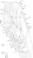
图1是本发明连接器组件的一第一实施例的一立体分解图;1 is an exploded perspective view of a first embodiment of the connector assembly of the present invention;
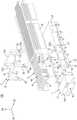
图2是该第一实施例的更进一步的一立体分解图;2 is a further exploded perspective view of the first embodiment;
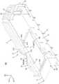
图3是该第一实施例的罩体与散热器的一局部立体分解图,图中散热器被翻转至底部朝上。3 is a partial exploded perspective view of the cover and the heat sink of the first embodiment, in which the heat sink is turned upside down.
图4是该第一实施例的一局部剖切的立体图,其中,可插拔模块尚未完全插入罩体;FIG. 4 is a partially cut-away perspective view of the first embodiment, wherein the pluggable module has not been fully inserted into the housing;
图5是表示如图4所示的该第一实施例的一局部剖切的侧视图;Fig. 5 is a side view showing a partial cutaway of the first embodiment shown in Fig. 4;
图6是该第一实施例的一局部剖切的立体图,其中,可插拔模块已完全插入罩体;Figure 6 is a partially cutaway perspective view of the first embodiment with the pluggable module fully inserted into the housing;
图7是表示如图6所示的该第一实施例的一局部剖切的侧视图;Fig. 7 is a side view showing a partial cutaway of the first embodiment shown in Fig. 6;
图8是本发明连接器组件的一第二实施例的一局部立体分解图;8 is a partial perspective exploded view of a second embodiment of the connector assembly of the present invention;
图9是该第二实施例的一局部剖切的立体图;以及Figure 9 is a partially cutaway perspective view of the second embodiment; and
图10是表示如图9所示的该第二实施例的一局部剖切的侧视图。FIG. 10 is a partially cut-away side view showing the second embodiment shown in FIG. 9 .
附图标记说明如下:The reference numerals are explained as follows:
100 连接器组件100 Connector Assembly
1 罩体1 cover
11 顶壁11 Top wall
12 底壁12 Bottom wall
13 侧壁13 Side walls
131 扣接凸块131 Buckle bump
14 后壁14 rear wall
15 插脚15 pins
16 插接空间16 Plug space
161 前端插口161 front socket
162 窗口162 windows
162a 后端凹部162a Rear recess
163 底部开口163 Bottom opening
17 接地件17 Grounding
171 弹性指部171 Elastic Fingers
18 前安装片18 Front Mounting Tab
181 榫接槽181 Mortise groove
19 后安装片19 Rear Mounting Tabs
2 插座连接器2 socket connectors
21 座体21 body
211 插接槽211 socket
22 端子22 terminals
3 可插拔模块3 pluggable modules
31 壳体31 Housing
311 插接部311 Socket
32 插接板32 Pinboard
321 接触指部321 Contact fingers
4 散热器4 Radiator
41 基板41 Substrate
411 热耦合部411 Thermal Coupling Section
411a 热耦合面411a Thermal coupling surface
411b 热界面材料411b Thermal Interface Materials
412 导引部412 Guide
413 受推凸部413 Pushed protrusion
42 散热鳍片42 cooling fins
43 侧板43 Side panels
431 辅助散热片431 Auxiliary heat sink
44 主弹簧作用部44 Main spring action part
441 主弹簧作用面441 Main spring action surface
45 辅助弹簧作用部45 Auxiliary spring action part
46 限位槽46 Limit slot
47 导光件安装槽47 Light guide mounting slot
5 施压构件5 Pressure components
51 框体51 Frame
511 前框511 Front frame
512 后框512 rear frame
513 侧框513 side frame
52 组装部52 Assembly Department
521 扣接孔521 Snap holes
53 主弹簧部53 Main spring part
54 辅助弹簧部54 Auxiliary spring part
6 导光件6 Light guide
61 导光管61 Light pipe
611 入光端611 light input end
612 出光端612 light output end
62 前安装柱62 Front Mounting Post
621 榫接块621 Mortise block
63 后安装柱63 Rear Mounting Post
631 插孔631 jack
64 后连接柱64 Rear connection post
641 卡槽641 card slot
7 导光件用连接件7 Connectors for light guides
71 容置孔71 accommodating hole
72 卡勾72 hook
73 定位柱73 Positioning post
8 支撑弹簧8 Support spring
D1 前后方向D1 Front and rear direction
D2 上下方向D2 up and down direction
D3 左右方向D3 left and right
具体实施方式Detailed ways
在本发明被详细描述之前,应当注意在以下的说明内容中,类似的元件是以相同的编号来表示。Before the present invention is described in detail, it should be noted that in the following description, similar elements are designated by the same reference numerals.
参阅图1至图3,本发明连接器组件100的一第一实施例,包含一罩体1、一插座连接器2、一可插拔模块3、一散热器4、一施压构件5、两个导光件6,以及一导光件用连接件7。需要说明的是,所述罩体1、所述插座连接器2、所述散热器4、所述施压构件5、所述导光件6与所述导光件用连接件7的数量皆可以各自依照需求做调整且可为堆叠或组合的构造,不以本第一实施例中的数量为限制。1 to 3, a first embodiment of the
该罩体1举例来说是以金属薄板经由模具冲压加工、弯折所构造而成,该罩体1用以设置于一电路板(图未示)且沿一前后方向D1(箭头方向为前,反向为后)延伸。该罩体1具有一顶壁11、与该顶壁11沿一上下方向D2(箭头方向为上,反向为下)相间隔的一底壁12、沿一左右方向D3(箭头方向为右,反向为左)相间隔且连接于该顶壁11与该底壁12之间的两个侧壁13、连接于该顶壁11与该两侧壁13的后缘的一后壁14,以及自该两侧壁13朝下延伸并适用于固定在所述电路板上及/或连接到接地轨迹(图未示)的多个插脚15。另外,该罩体1还具有由该顶壁11、该底壁12、该两侧壁13与该后壁14共同构成界定且位于内部的一插接空间16、位于前端且连通于该插接空间16并供该可插拔模块3插入的一前端插口161、形成于该顶壁11且自该顶壁11的前段处朝后延伸并连通于该插接空间16的一窗口162,以及位于该底壁12后方且连通该插接空间16的一底部开口163。The
该插座连接器2(见图1)机械性且电性地设置于该电路板,该插座连接器2具有绝缘的一座体21,以及多个端子22,该座体21具有一插接槽211,这些端子22设于该插接槽211内且其尾部(图未示)电性并机械地连接于该电路板。该插座连接器2是通过该底部开口163地以该罩体1罩盖,以使该插座连接器2设于该插接空间16的后段,但不以此为限。The socket connector 2 (see FIG. 1 ) is mechanically and electrically disposed on the circuit board. The
该可插拔模块3包含一壳体31、一插接板32,以及一线缆(图未示),该壳体31包括一插接部311,该插接板32突出该插接部311且该插接板32上具有多个接触指部321,该线缆设于该壳体31且机械性并电性地连接到该插接板32。该可插拔模块3自该前端插口161进入该罩体1内后,该可插拔模块3的插接部311末端的插接板32能插入该插座连接器2的插接槽211,而使该插接板32的接触指部321接触于该插座连接器2的插接槽211内的端子22,以使该可插拔模块3与该插座连接器2彼此对接。此外,该罩体1前段邻近该前端插口161处可设置于一机壳(图未示)的一安装孔,该罩体1的前端插口161处还设有多个接地件17,所述接地件17具有自该前端插口161处朝后延伸且分布于该罩体1外侧与该罩体1内侧的多个弹性指部171,这些弹性指部171中位于该罩体1外侧者用于与该机壳的安装孔的周缘处部分接触,这些弹性指部171中位于该罩体1内侧者用于与该可插拔模块3接触。The
参阅图1至图4,该散热器4设于该罩体1的顶壁11,该散热器4具有位于该顶壁11的一基板41、沿该左右方向D3彼此并排且自基板41的顶面朝上一体延伸出的多个散热鳍片42,以及连接于该基板41的左右两侧缘且与这些散热鳍片42间隔并排的多个侧板43。该基板41的底面具有朝下凸伸且用以自该窗口162伸入该插接空间16的一热耦合部411、朝下凸伸且位于该热耦合部411前方的一导引部412、以及设置在该热耦合部411后端的一受推凸部413,,该热耦合部411具有位于底部的一热耦合面411a,该受推凸部413呈朝下凸伸出热耦合面411a的柱状且自该窗口162的后端伸入该插接空间16内;在本第一实施例中,该热耦合面411a上设有一热界面材料411b(见图4),该热界面材料411b(Thermal InterfaceMaterial)能够充分地填充接触表面的接缝或空隙以减少接触面间的接触热阻,该热界面材料411b可以选自例如具有高导热性、高柔韧性、可压缩特性、绝缘性、耐磨性等特性的材料的组合,且举例来说可以为底材与相变化材料(phase change material)的材料组合,例如其可以是两层以上的构造,其外层底材可以是具备导热性、润滑性、耐磨性、抗撕裂性的材料(例如铁氟龙(Teflon)),而其内层材料则为相变化材料。另外,该热界面材料411b也可通过材料的组合变化同时具备电磁波屏蔽作用(EMI Shielding)。另外,在本第一实施例中,所述侧板43在位于该基板41上方的部分形成有朝外凸伸且沿该上下方向D2并排的辅助散热片431。Referring to FIGS. 1 to 4 , the
该施压构件5组装该散热器4至该罩体1的顶壁11,该施压构件5具有一框体51,以及自该框体51的左右侧边朝下延伸并组装于该罩体1的该两侧壁13的四个组装部52。该框体51具有沿该前后方向D1间隔并排的一前框511与一后框512,以及连接于该前框511与该后框512且沿该左右方向D3间隔并排的两侧框513。详细来说,该罩体1的每一侧壁13形成有两个扣接凸块131,每一组装部52形成有与对应的侧壁13的扣接凸块131对应扣接的一扣接孔521,藉由所述扣接凸块131与所述扣接孔521使这些组装部52组装于该罩体1的侧壁13。该散热器4还具有分别位于左右两侧且设置于所述侧板43的两个主弹簧作用部44,以及分别设置于所述侧板43且分别位于该两主弹簧作用部44的前方与后方的四个辅助弹簧作用部45,其中,该主弹簧作用部44具有朝后且朝下倾斜地延伸的一主弹簧作用面441。该施压构件5还具有分别设于该两侧框513且朝后且朝下倾斜地延伸的两个主弹簧部53,以及自所述前框511的两端与所述后框512的两端朝下且朝前或朝后反曲弯折形成且呈弹性脚结构的多个辅助弹簧部54。该两主弹簧部53分别对应于该两主弹簧作用部44的主弹簧作用面441,这些辅助弹簧部54分别对应于这些辅助弹簧作用部45。The
参阅图1、图4至图7,通过该施压构件5使该散热器4能相对该罩体1在位于前方的一非作用位置(如图4及图5所示)以及位于后方的一作用位置(如图6及图7所示)之间移动,在本第一实施例中,该散热器4还具有形成于这些散热鳍片42且分别容置该施压构件5的前框511与后框512的两个限位槽46,该两限位槽46分别与该施压构件5的前框511与后框512之间能产生限位该散热器4在该前后方向D1上的位置的作用,当该散热器4位于该非作用位置,该两限位槽46的后缘能朝前方向地靠抵在该施压构件5的前框511与后框512,当该散热器4位于该作用位置,该两限位槽46的前缘能朝后方向地靠抵在该施压构件5的前框511与后框512,但该散热器4也可以是通过设置于该罩体1及/或该施压构件5的其他限位结构而被限位,不以本第一实施例为限。Referring to FIGS. 1 , 4 to 7 , the
如图4及图5所示,当该散热器4位于该非作用位置,这些辅助弹簧部54朝下地施压于这些辅助弹簧作用部45,该散热器4的热耦合面411a通过该顶壁11的窗口162进入该插接空间16,此时该散热器4的主弹簧作用部44不接触该施压构件5的主弹簧部53,且该施压构件5的主弹簧部53不作用于该散热器4的主弹簧作用部44。当该可插拔模块3插入该罩体1的插接空间16,该可插拔模块3将先推动该散热器4的导引部412,以使该散热器4克服这些辅助弹簧部54所提供的作用力并朝上抬升,接着该散热器4的热耦合面411a上的热界面材料411b将接触到该可插拔模块3的上表面,此时该散热器4的主弹簧作用部44仍不接触该施压构件5的主弹簧部53,且该施压构件5的主弹簧部53不作用于该散热器4的主弹簧作用部44。如图6及图7所示,最后,当该可插拔模块3朝后推动该散热器4的受推凸部413及到达与该插座连接器2对接的行程中,使该散热器4由该非作用位置朝后移动至该作用位置,需要说明的是,在该散热器4的受推凸部413被朝后推动后,该受推凸部413将容纳于该窗口162的后端的一后端凹部162a处。当该散热器4在该作用位置,该散热器4的主弹簧作用部44与该施压构件5的主弹簧部53接触,且该施压构件5的主弹簧部53作用于该散热器4的主弹簧作用部44的主弹簧作用面441,以提供朝下的作用力使该散热器4的热耦合面411a上的热界面材料411b通过该窗口162具正向力地接触于该可插拔模块3的上表面。整体来说,在本第一实施例中,该散热器4在该可插拔模块3插入的过程中是由该非作用位置朝上且朝后地移动至该作用位置。另外,需要说明的是,在一变化实施例中,该散热器4的热耦合面411a也可以不通过该热界面材料411b而是直接地接触该可插拔模块3的上表面。As shown in FIG. 4 and FIG. 5 , when the
进一步来说,由于该散热器4的主弹簧作用部44与该施压构件5的主弹簧部53的倾斜构造,使当该散热器4在该作用位置时,该施压构件5的主弹簧部53不仅提供给该散热器4朝下的作用力,同时也提供给该散热器4朝前的作用力。因此,当该可插拔模块3自该罩体1的插接空间16退出时,该施压构件5的主弹簧部53的作用力与该可插拔模块3的摩擦力将使该散热器4朝前移动,且该施压构件5的辅助弹簧部54将使该散热器4朝下移动,以使该散热器4自该作用位置移动至非作用位置。Further, due to the inclined structure of the main
在此过程中,该施压构件5的主弹簧部53提供的较主要且使该散热器4的热耦合部411与该可插拔模块3的表面紧密接触的较大作用力,该施压构件5的辅助弹簧部54则提供的较次要且使该散热器4的热耦合部411通过该窗口162进入该插接空间16的较小预作用力。并且,由于该施压构件5的主弹簧部53是在该散热器4被该可插拔模块3朝后推动之后,才对该散热器4提供使该散热器4的热耦合面411a紧密接触于该可插拔模块3表面的作用力,因此能够减少该散热器4的热耦合面411a与该可插拔模块3之间在该可插拔模块3的插入过程中所产生的摩擦情形,以防止该散热器4的热耦合面411a的磨损问题,或是该散热器4的热耦合面411a所设置的该热界面材料411b被刮破的问题。During this process, the
该散热器4还具有由这些散热鳍片42与该两侧板43共同界定且沿该前后方向D1延伸的两个导光件安装槽47,该罩体1还具有位于近前端处且自该两侧壁13朝上延伸的两个前安装片18,以及位于后端处且自该两侧壁13朝后延伸的两个后安装片19。该两导光件6设于该罩体1且分别容置于该两导光件安装槽47。每一导光件6具有各自具有两个导光管61、连接于该两导光管61且朝下延伸的一前安装柱62、连接于该两导光管61且朝下延伸的一后安装柱63,以及连接于该两导光管61的一后连接柱64。每一导光管61具有朝下且用以面对该电路板的发光元件的一入光端611,以及朝前的一出光端612。该前安装柱62设置于该罩体1的对应的前安装片18,该后安装柱63设置于该罩体1的对应的后安装片19。该前安装片18具有一榫接槽181,该前安装柱62具有用以榫接于该榫接槽181的一榫接块621,该后安装柱63具有供该后安装片19插入的一插孔631,藉此使该两导光管61组装于该罩体1。The
该导光件用连接件7设于该两导光件6与该电路板的发光元件之间。该导光件用连接件7具有多个容置孔71,各容置孔71的两端分别容置对应的导光件6的导光管61的入光端611以及对应的发光元件,以确保这些发光元件所发出的光线能各自进入对应的导光件6的导光管61的入光端611。另外,每一导光件6的后连接柱64形成有位于内侧的一卡槽641,该导光件用连接件7还具有由内而外卡固于对应的导光件6的卡槽641的两个卡勾72,以及用以穿设于该电路板的定位柱73,藉此使该导光件用连接件7固定于该两导光件6与该电路板之间。The connecting
参阅图8至图10,本发明连接器组件100的一第二实施例与该第一实施例的不同之处在于,该罩体1的顶壁11与该散热器4的基板41之间设有多个支撑弹簧8。进一步来说,在本第二实施例中,罩体1的顶壁11具有位于该窗口162旁且呈一体构造形成的弹片状的这些支撑弹簧8,但需要说明的是,在其他实施方式中,这些支撑弹簧8也可以是一体构造地形成于该散热器4,或这些支撑弹簧8也可以为独立的构件。Referring to FIG. 8 to FIG. 10 , the difference between the second embodiment of the
当该散热器4在该非作用位置,该支撑弹簧8将该散热器4朝上撑高且使该散热器4的基板41与该罩体1的顶壁11相间隔,并使该散热器4的热耦合面411a不进入该罩体1的插接空间16,此时该散热器4的主弹簧作用部44不接触该施压构件5的主弹簧部53,且该施压构件5的主弹簧部53不作用于该散热器4的主弹簧作用部44。当该可插拔模块3(见图1)插入该罩体1的插接空间16及在推动该受推凸部413之前的行程中,该散热器4的主弹簧作用部44仍不接触该施压构件5的主弹簧部53,且该施压构件5的主弹簧部53不作用于该散热器4的主弹簧作用部44,因此,此时该散热器4的热耦合面411a仍不进入该罩体1的插接空间16与该可插拔模块3接触。最后,当该可插拔模块3推动该散热器4的受推凸部413及到达与该插座连接器2(见图1)对接的行程中,该散热器4由该非作用位置朝后移动至该作用位置,当该散热器4在该作用位置,该散热器4的主弹簧作用部44与该施压构件5的主弹簧部53接触,且该施压构件5的主弹簧部53作用于该散热器4的主弹簧作用部44的主弹簧作用面441,以提供朝下的作用力将该散热器4下压使该散热器4的热耦合面411a通过该窗口162进入该罩体1的插接空间16,并使该散热器4的热耦合面411a上的热界面材料411b具正向力地接触于该可插拔模块3的上表面。也就是说,在所述可插拔模块3推动所述散热器4的受推凸部413而使所述散热器4移动至所述作用位置之前,所述散热器4的热耦合面411a不接触所述可插拔模块3的表面,藉此能够更进一步地防止所述散热器4的热耦合面411a的磨损问题,或是所述散热器4的热耦合面411a所设置的所述热界面材料411b被刮破的问题。整体来说,在本第二实施例中,该散热器4在该可插拔模块3插入的过程中是由该非作用位置朝后且朝下地移动至该作用位置。When the
另外,当该可插拔模块3自该罩体1的插接空间16退出时,该施压构件5的主弹簧部53的作用力与该可插拔模块3的摩擦力将使该散热器4朝前移动,且这些支撑弹簧8将使该散热器4朝上移动,以使该散热器4自该作用位置移动至非作用位置。In addition, when the
综上所述,本发明连接器组件100的所述施压构件5不仅用于组装所述散热器4,同时也提供了能用于作用在散热器4的主弹簧部53,并且,所述施压构件5的主弹簧部53是在所述散热器4被所述可插拔模块3朝后推动之后,才对所述散热器4提供使所述散热器4的热耦合面411a接触于所述可插拔模块3表面的作用力,如此能够减少所述散热器4的热耦合面411a与所述可插拔模块3之间在所述可插拔模块3的插入过程中所产生的摩擦情形,以防止所述散热器4的热耦合面411a的磨损问题,或是所述散热器4的热耦合面411a所设置的所述热界面材料411b被刮破的问题。To sum up, the pressing
然而以上所述者,仅为本发明的实施例而已,当不能以此限定本发明实施的范围,凡是依本发明权利要求及专利说明书内容所作的简单的等效变化与修饰,皆仍属本发明专利涵盖的范围内。However, the above descriptions are only examples of the present invention, which should not limit the scope of the present invention. All simple equivalent changes and modifications made according to the claims of the present invention and the contents of the patent specification are still within the scope of the present invention. within the scope of the invention patent.
Claims (10)
Translated fromChinesePriority Applications (1)
| Application Number | Priority Date | Filing Date | Title |
|---|---|---|---|
| CN202110260447.2ACN115084952A (en) | 2021-03-10 | 2021-03-10 | Connector assembly |
Applications Claiming Priority (1)
| Application Number | Priority Date | Filing Date | Title |
|---|---|---|---|
| CN202110260447.2ACN115084952A (en) | 2021-03-10 | 2021-03-10 | Connector assembly |
Publications (1)
| Publication Number | Publication Date |
|---|---|
| CN115084952Atrue CN115084952A (en) | 2022-09-20 |
Family
ID=83240672
Family Applications (1)
| Application Number | Title | Priority Date | Filing Date |
|---|---|---|---|
| CN202110260447.2APendingCN115084952A (en) | 2021-03-10 | 2021-03-10 | Connector assembly |
Country Status (1)
| Country | Link |
|---|---|
| CN (1) | CN115084952A (en) |
Citations (14)
| Publication number | Priority date | Publication date | Assignee | Title |
|---|---|---|---|---|
| CN1647322A (en)* | 2002-03-06 | 2005-07-27 | 蒂科电子公司 | Transceiver module assembly ejector mechanism |
| US20050162834A1 (en)* | 2004-01-23 | 2005-07-28 | Takeshi Nishimura | Electronics connector with heat sink |
| CN1677759A (en)* | 2004-03-29 | 2005-10-05 | 安普泰科电子有限公司 | card connector |
| US20070183128A1 (en)* | 2006-02-07 | 2007-08-09 | Methode Electronics, Inc. | Heat sink gasket |
| US20090296351A1 (en)* | 2007-12-11 | 2009-12-03 | Sumitomo Electric Industries, Ltd. | Mechanism to make a heat sink in contact with a pluggable transceiver, a pluggable optical transceiver and a cage assembly providing the same |
| CN101930100A (en)* | 2009-01-14 | 2010-12-29 | 泰科电子公司 | The Straddle mount connector that is used for pluggable transceiver module |
| US20120052720A1 (en)* | 2010-08-06 | 2012-03-01 | David James J | Electrical connector assembly including compliant heat sink |
| US8599559B1 (en)* | 2012-05-30 | 2013-12-03 | Tyco Electronics Corporation | Cage with a heat sink mounted on its mounting side and an EMI gasket with its fingers electrically connected to the mounting side |
| CN103855543A (en)* | 2012-12-05 | 2014-06-11 | 莫列斯公司 | Shielding cage and receptacle assembly |
| US20170214170A1 (en)* | 2016-01-21 | 2017-07-27 | Nextronics Engineering Corp. | Connector housing with heat dissipation structure |
| CN110249718A (en)* | 2017-01-12 | 2019-09-17 | 申泰公司 | Frame with attached heatsink |
| US20200067230A1 (en)* | 2018-08-27 | 2020-02-27 | Fujitsu Limited | Connector cage |
| CN210404248U (en)* | 2019-04-08 | 2020-04-24 | 莫列斯有限公司 | Electrical connection device |
| CN112217029A (en)* | 2019-07-12 | 2021-01-12 | 莫列斯有限公司 | Connector assembly |
- 2021
- 2021-03-10CNCN202110260447.2Apatent/CN115084952A/enactivePending
Patent Citations (15)
| Publication number | Priority date | Publication date | Assignee | Title |
|---|---|---|---|---|
| CN1647322A (en)* | 2002-03-06 | 2005-07-27 | 蒂科电子公司 | Transceiver module assembly ejector mechanism |
| US20050162834A1 (en)* | 2004-01-23 | 2005-07-28 | Takeshi Nishimura | Electronics connector with heat sink |
| CN1677759A (en)* | 2004-03-29 | 2005-10-05 | 安普泰科电子有限公司 | card connector |
| US20070183128A1 (en)* | 2006-02-07 | 2007-08-09 | Methode Electronics, Inc. | Heat sink gasket |
| US20090296351A1 (en)* | 2007-12-11 | 2009-12-03 | Sumitomo Electric Industries, Ltd. | Mechanism to make a heat sink in contact with a pluggable transceiver, a pluggable optical transceiver and a cage assembly providing the same |
| CN101930100A (en)* | 2009-01-14 | 2010-12-29 | 泰科电子公司 | The Straddle mount connector that is used for pluggable transceiver module |
| US20120052720A1 (en)* | 2010-08-06 | 2012-03-01 | David James J | Electrical connector assembly including compliant heat sink |
| CN202308382U (en)* | 2010-08-06 | 2012-07-04 | Fci公司 | Electric connector system and spring clamp |
| US8599559B1 (en)* | 2012-05-30 | 2013-12-03 | Tyco Electronics Corporation | Cage with a heat sink mounted on its mounting side and an EMI gasket with its fingers electrically connected to the mounting side |
| CN103855543A (en)* | 2012-12-05 | 2014-06-11 | 莫列斯公司 | Shielding cage and receptacle assembly |
| US20170214170A1 (en)* | 2016-01-21 | 2017-07-27 | Nextronics Engineering Corp. | Connector housing with heat dissipation structure |
| CN110249718A (en)* | 2017-01-12 | 2019-09-17 | 申泰公司 | Frame with attached heatsink |
| US20200067230A1 (en)* | 2018-08-27 | 2020-02-27 | Fujitsu Limited | Connector cage |
| CN210404248U (en)* | 2019-04-08 | 2020-04-24 | 莫列斯有限公司 | Electrical connection device |
| CN112217029A (en)* | 2019-07-12 | 2021-01-12 | 莫列斯有限公司 | Connector assembly |
Similar Documents
| Publication | Publication Date | Title |
|---|---|---|
| TWI757113B (en) | connector assembly | |
| CN114623722A (en) | Connector assembly | |
| TWI753695B (en) | connector assembly | |
| TW202218266A (en) | Connector assembly capable of surely protecting a heat conducting pad and preventing the heat conducting pad from being scratched by a pluggable module | |
| TW202220309A (en) | Connector assembly including a leading shield cover, a shield enclosure and a heat sink | |
| CN114256699B (en) | Connector components | |
| TWI819887B (en) | Connector components | |
| TW202239085A (en) | Connector assembly that comprises a hood, a receptacle connector, an insertion and removal module, a heat dissipater, and a heat dissipater lifting structure | |
| CN115084952A (en) | Connector assembly | |
| CN219777985U (en) | Connector assembly | |
| US20240027709A1 (en) | Connector assembly | |
| TWI832606B (en) | Connector components | |
| TWI758118B (en) | connector assembly | |
| TW202318739A (en) | Connector assembly including a shielding cover, a heat sink and a buckle | |
| TWI816488B (en) | Connector components | |
| TWI835215B (en) | Connector components | |
| TWI880575B (en) | Connector Assemblies | |
| TWI883770B (en) | Connector Assemblies | |
| TWI892577B (en) | Connector assembly | |
| TWI755193B (en) | connector assembly | |
| TWI844924B (en) | Connector Assemblies | |
| CN114498203B (en) | Connector components | |
| CN218867463U (en) | Connector assembly | |
| US20240364056A1 (en) | Connector assembly | |
| CN113809600B (en) | Guide shield and connector assembly |
Legal Events
| Date | Code | Title | Description |
|---|---|---|---|
| PB01 | Publication | ||
| PB01 | Publication | ||
| SE01 | Entry into force of request for substantive examination | ||
| SE01 | Entry into force of request for substantive examination |