CN115075743A - Bridge plug setting releasing adapter and matched tool and using method thereof - Google Patents
Bridge plug setting releasing adapter and matched tool and using method thereofDownload PDFInfo
- Publication number
- CN115075743A CN115075743ACN202210727704.3ACN202210727704ACN115075743ACN 115075743 ACN115075743 ACN 115075743ACN 202210727704 ACN202210727704 ACN 202210727704ACN 115075743 ACN115075743 ACN 115075743A
- Authority
- CN
- China
- Prior art keywords
- bridge plug
- sleeve
- pull rod
- wall
- setting tool
- Prior art date
- Legal status (The legal status is an assumption and is not a legal conclusion. Google has not performed a legal analysis and makes no representation as to the accuracy of the status listed.)
- Pending
Links
- 238000000034methodMethods0.000titleclaimsabstractdescription22
- 238000010008shearingMethods0.000claimsabstractdescription39
- 238000007789sealingMethods0.000claimsdescription31
- 230000000717retained effectEffects0.000claimsdescription4
- 210000001503jointAnatomy0.000claims2
- 238000010586diagramMethods0.000description5
- 230000008569processEffects0.000description5
- 230000007246mechanismEffects0.000description4
- 239000002184metalSubstances0.000description3
- 229910052751metalInorganic materials0.000description3
- 238000012986modificationMethods0.000description3
- 230000004048modificationEffects0.000description3
- 238000003032molecular dockingMethods0.000description3
- RYGMFSIKBFXOCR-UHFFFAOYSA-NCopperChemical compound[Cu]RYGMFSIKBFXOCR-UHFFFAOYSA-N0.000description1
- 238000009825accumulationMethods0.000description1
- 230000009471actionEffects0.000description1
- 230000009286beneficial effectEffects0.000description1
- 229910052802copperInorganic materials0.000description1
- 239000010949copperSubstances0.000description1
- 238000005553drillingMethods0.000description1
- 230000000694effectsEffects0.000description1
- 238000001125extrusionMethods0.000description1
- 238000004519manufacturing processMethods0.000description1
- 239000003208petroleumSubstances0.000description1
- 238000005086pumpingMethods0.000description1
- 239000003079shale oilSubstances0.000description1
- 239000002195soluble materialSubstances0.000description1
Images


Classifications
- E—FIXED CONSTRUCTIONS
- E21—EARTH OR ROCK DRILLING; MINING
- E21B—EARTH OR ROCK DRILLING; OBTAINING OIL, GAS, WATER, SOLUBLE OR MELTABLE MATERIALS OR A SLURRY OF MINERALS FROM WELLS
- E21B17/00—Drilling rods or pipes; Flexible drill strings; Kellies; Drill collars; Sucker rods; Cables; Casings; Tubings
- E21B17/02—Couplings; joints
- E21B17/021—Devices for subsurface connecting or disconnecting by rotation
- E—FIXED CONSTRUCTIONS
- E21—EARTH OR ROCK DRILLING; MINING
- E21B—EARTH OR ROCK DRILLING; OBTAINING OIL, GAS, WATER, SOLUBLE OR MELTABLE MATERIALS OR A SLURRY OF MINERALS FROM WELLS
- E21B23/00—Apparatus for displacing, setting, locking, releasing or removing tools, packers or the like in boreholes or wells
- E21B23/01—Apparatus for displacing, setting, locking, releasing or removing tools, packers or the like in boreholes or wells for anchoring the tools or the like
- E—FIXED CONSTRUCTIONS
- E21—EARTH OR ROCK DRILLING; MINING
- E21B—EARTH OR ROCK DRILLING; OBTAINING OIL, GAS, WATER, SOLUBLE OR MELTABLE MATERIALS OR A SLURRY OF MINERALS FROM WELLS
- E21B33/00—Sealing or packing boreholes or wells
- E21B33/10—Sealing or packing boreholes or wells in the borehole
- E21B33/13—Methods or devices for cementing, for plugging holes, crevices or the like
- E21B33/134—Bridging plugs
Landscapes
- Engineering & Computer Science (AREA)
- Life Sciences & Earth Sciences (AREA)
- Geology (AREA)
- Mining & Mineral Resources (AREA)
- Physics & Mathematics (AREA)
- Environmental & Geological Engineering (AREA)
- Fluid Mechanics (AREA)
- General Life Sciences & Earth Sciences (AREA)
- Geochemistry & Mineralogy (AREA)
- Mechanical Engineering (AREA)
- Devices For Opening Bottles Or Cans (AREA)
Abstract
Translated fromChinese
Description
Translated fromChinese技术领域technical field
本发明涉及油气开采技术领域,具体涉及一种桥塞坐封丢手适配器及其配套工具、使用方法。The invention relates to the technical field of oil and gas exploitation, in particular to a bridge plug setting and discarding hand adapter, a matching tool and a method of using the same.
背景技术Background technique
石油工程用丢手机构是一种常用的井下工作,在钻井上通常以安全接头的形式出现,在固井和采油等方面通常叫做丢手工具或自动脱挂结构。按照用途来区分,有主动丢手机构和被动丢手机构。在油气工业领域中,特别是页岩气、页岩油的开采中,可溶解桥塞已经得到了大量的应用。桥塞坐封丢手适配器是可溶解桥塞的重要部件,用于连接在坐封工具与桥塞之间,辅助桥塞坐封工具完成对桥塞的坐封丢手动作。适配器的尺寸规格通常是根据桥塞的结构尺寸进行相应调整,目前应用最为广泛的桥塞适配器主要包括推筒、丢手接头、连接杆以及锁紧销钉。随着近几年页岩气的大规模开发,泵送桥塞与多级射孔联作分段工艺应用也越来越多,随之而来的是桥塞的种类也越来越多。The hand-throwing mechanism for petroleum engineering is a commonly used downhole work. It usually appears in the form of a safety joint in drilling. It is usually called a hand-throwing tool or an automatic detachment structure in cementing and oil production. According to the use, there are active throwing mechanisms and passive throwing mechanisms. In the field of oil and gas industry, especially in the exploitation of shale gas and shale oil, dissolvable bridge plugs have been widely used. The bridge plug setting and throwing adapter is an important part of the dissolvable bridge plug, which is used to connect between the setting tool and the bridge plug, and assist the bridge plug setting tool to complete the setting and throwing action of the bridge plug. The size of the adapter is usually adjusted according to the structural size of the bridge plug. Currently, the most widely used bridge plug adapters mainly include push cylinders, hand-throwing joints, connecting rods and locking pins. With the large-scale development of shale gas in recent years, there have been more and more applications of pumping bridge plugs and multi-stage perforating sub-processes, and there are more and more types of bridge plugs.
现有的桥塞坐封丢手适配器,与可溶解金属密封桥塞与坐封工具配套使用,其丢手方式主要采用剪切销钉丢手和剪切螺纹丢手两种方式。常规的丢手剪切机构往往是直接安装在桥塞上,若采用材质为铜的剪切销钉丢手,由于可溶解桥塞的可溶解性能的要求,一方面会降低桥塞的溶解性能;另一方面,剪切销钉残留物在井下堆积,有可能造成通井遇卡的风险。若采用剪切螺纹丢手方式:螺纹往往是设计在桥塞下部的引鞋上,由于螺纹是可溶材料加工而成,可溶解桥塞在入井时即开始缓慢溶解,当桥塞到达预定坐封位置后,剪切螺纹已经部分溶解,螺纹剪切力降低,可能导致桥塞不能完全坐封,进而导致密封失效。The existing bridge plug setting and discarding adapter is used in conjunction with a dissolvable metal sealing bridge plug and a setting tool, and the discarding methods mainly adopt two methods of discarding the hand by shearing pins and discarding by shearing threads. The conventional drop-hand shearing mechanism is often installed directly on the bridge plug. If the shear pin made of copper is used to drop the hand, due to the requirements of the soluble performance of the soluble bridge plug, on the one hand, the solubility of the bridge plug will be reduced; On the other hand, the accumulation of shear pin residues in the well may cause the risk of getting stuck in the well. If the method of cutting the thread and throwing hands is adopted: the thread is often designed on the guide shoe at the lower part of the bridge plug. Since the thread is made of soluble material, the soluble bridge plug starts to dissolve slowly when it enters the well. When the bridge plug reaches the predetermined seat After the sealing position, the shear thread has been partially dissolved, and the shear force of the thread is reduced, which may cause the bridge plug to not be fully set, resulting in seal failure.
总而言之,现有的可溶解金属密封桥塞要么在丢手过程中有较高的通井遇卡的风险,要么不能完全坐封,进而导致密封失效。All in all, the existing dissolvable metal sealing bridge plugs either have a high risk of getting stuck in the well during the process of being thrown away, or they cannot be completely set, resulting in sealing failure.
发明内容SUMMARY OF THE INVENTION
本发明的目的在于提供一种桥塞坐封丢手适配器及其配套工具、使用方法,用以解决现有的可溶解金属密封桥塞要么在丢手过程中有较高的通井遇卡的风险,要么不能完全坐封,进而导致密封失效的问题。The purpose of the present invention is to provide a bridge plug setting and discarding adapter, its supporting tool, and a method of use, to solve the problem of the existing dissolvable metal sealing bridge plug or the high well-passing and jamming process in the process of discarding. Risk, or not fully set, resulting in seal failure problems.
本发明提供一种桥塞坐封丢手适配器,包括:The present invention provides a bridge plug setting and discarding adapter, comprising:
推筒;push cylinder;
拉杆,其上端穿设于推筒内且拉杆的底端伸出所述推筒;a pull rod, the upper end of which is inserted into the push cylinder and the bottom end of the pull rod protrudes from the push cylinder;
内剪切环,固定套在拉杆的外壁上;The inner shear ring is fixed on the outer wall of the tie rod;
外剪切套,活动设置在拉杆的外侧,且所述内剪切环与所述外剪切套之间通过剪切销钉固定连接;The outer shearing sleeve is movably arranged on the outer side of the tie rod, and the inner shearing ring and the outer shearing sleeve are fixedly connected by a shearing pin;
弹性套,套在拉杆上,且其顶端伸入至所述外剪切套内;an elastic sleeve, which is sleeved on the pull rod, and whose top end extends into the outer shear sleeve;
调整环,套在弹性套的固定套部上,恰好封堵推筒底端与拉杆外壁之间的环形空间;The adjusting ring is sleeved on the fixed sleeve part of the elastic sleeve, and just blocks the annular space between the bottom end of the push cylinder and the outer wall of the pull rod;
其中,拉杆的上部用于在推筒内对接坐封工具,弹性套用于对接桥塞,当桥塞坐封丢手适配器置于外套管内,推动坐封工具带动拉杆向下运动,完成桥塞坐封于外套管,直至所述剪切销钉被剪断,向上拉动坐封工具带动拉杆,所述剪切销钉随着拉杆从弹性套内抽出,弹性套也随之脱离外套管,使桥塞滞留外套管内,完成丢手。Among them, the upper part of the tie rod is used for docking the setting tool in the push cylinder, and the elastic sleeve is used for docking the bridge plug. When the bridge plug setting and discarding adapter is placed in the outer casing, the setting tool is pushed to drive the tie rod to move downward to complete the bridge plug setting. It is sealed in the outer casing until the shearing pin is cut, and the setting tool is pulled upward to drive the pull rod. The shearing pin is pulled out from the elastic sleeve along with the pulling rod, and the elastic sleeve is also separated from the outer casing, so that the bridge plug stays in the outer casing. In the tube, complete the drop.
优选地,所述弹性套包括固定套部和活动套部,所述活动套部与所述固定套部固定对接且一体成型;所述弹性套套在拉杆上,且所述固定套部的顶端伸入至所述外剪切套内,弹性套顶端的外壁与外剪切套的内壁通过外螺纹连接;所述固定套部内壁上设置有内凸起,所述固定套部的内凸起紧抱在所述拉杆的外壁上;所述活动套部包括若干束弹性条,若干束弹性条环向间隔围成一个环形簇,每个弹性条前端的外侧面设置有外凸起;所述活动套部的若干束弹性条围绕在所述拉杆的底端的外壁上。Preferably, the elastic sleeve includes a fixed sleeve part and a movable sleeve part, the movable sleeve part is fixedly connected to the fixed sleeve part and integrally formed; the elastic sleeve is sleeved on the pull rod, and the top end of the fixed sleeve part extends into the outer shearing sleeve, the outer wall of the top end of the elastic sleeve and the inner wall of the outer shearing sleeve are connected by external threads; the inner wall of the fixing sleeve is provided with an inner protrusion, and the inner protrusion of the fixing sleeve is tightly hugged on the outer wall of the tie rod; the movable sleeve part includes several bundles of elastic strips, and the several bundles of elastic strips are circumferentially spaced to form an annular cluster, and the outer side of the front end of each elastic strip is provided with an outer protrusion; Several bundles of elastic strips of the sleeve portion surround the outer wall of the bottom end of the tie rod.
优选地,所述调整环上端粗、下端细,呈中空的圆台形,所述调整环的内壁套在推筒底端对应的弹性套的固定套部的外壁上,弹性套的外壁与调整环的内壁通过螺纹连接,推筒底端的内壁套在调整环的外壁上。Preferably, the upper end of the adjustment ring is thick and the lower end is thin, and is in the shape of a hollow truncated cone. The inner wall of the push cylinder is connected by threads, and the inner wall of the bottom end of the push cylinder is sleeved on the outer wall of the adjusting ring.
本发明还公开了一种桥塞坐封丢手适配器的配套工具,与上述的桥塞坐封丢手适配器相互配套使用,包括:The invention also discloses a matching tool for the bridge plug setting and throwing-hand adapter, which is used together with the above-mentioned bridge plug setting and throwing-hand adapter, including:
坐封工具,其底端设置于推筒顶端内且与拉杆的顶端对接;a setting tool, the bottom end of which is arranged in the top end of the push cylinder and is butted with the top end of the pull rod;
外套管,套在坐封工具和桥塞坐封丢手适配器的外侧;The outer sleeve is sleeved on the outside of the setting tool and the bridge plug setting and discarding adapter;
桥塞,坐封于所述弹性套与所述外套管之间的环形空间。The bridge plug is set in the annular space between the elastic sleeve and the outer sleeve.
具体地,所述坐封工具包括坐封工具运动套和坐封工具芯轴,所述坐封工具运动套的底端内壁边缘向外延伸形成坐封工具内凸缘,所述坐封工具芯轴顶端的外壁固定套设在坐封工具运动套的坐封工具内凸缘的内壁,推筒顶端的内壁与坐封工具运动套的坐封工具内凸缘的外壁通过螺纹固定连接;所述坐封工具芯轴的底端的端面设置有拉杆槽,拉杆的顶端设置于坐封工具芯轴的拉杆槽内,并与拉杆槽的内壁通过螺纹固定连接。Specifically, the setting tool includes a setting tool moving sleeve and a setting tool mandrel, the bottom inner wall edge of the setting tool moving sleeve extends outward to form an inner flange of the setting tool, and the setting tool core The outer wall of the top end of the shaft is fixedly sleeved on the inner wall of the inner flange of the setting tool of the moving sleeve of the setting tool, and the inner wall of the top end of the push cylinder and the outer wall of the inner flange of the setting tool of the moving sleeve of the setting tool are fixedly connected by threads; The end face of the bottom end of the mandrel of the setting tool is provided with a pull rod groove, and the top end of the pull rod is arranged in the pull rod groove of the mandrel of the setting tool and is fixedly connected with the inner wall of the pull rod groove by threads.
具体地,所述桥塞包括桥塞锥体、桥塞密封环、桥塞卡瓦、桥塞引鞋,所述桥塞锥体上端大、下端小,呈中空的圆台形;桥塞锥体顶端的内壁边缘向外延伸形成桥塞内凸缘,推筒底端的外壁边缘向外延伸形成外凸缘,所述推筒的外凸缘紧套在桥塞锥体的桥塞内凸缘的外壁上;所述桥塞锥体顶端的桥塞内凸缘的内壁设置为第一内锥面,调整环的外侧面设置为外锥面,且桥塞锥体的第一内锥面与调整环的外锥面相适配,桥塞锥体的第一内锥面固定套在调整环的外锥面上;所述桥塞密封环的内壁上端大、下端小,桥塞密封环的内壁设置为第二内锥面,且桥塞密封环的第二内锥面与桥塞锥体的外侧面相互适配,桥塞密封环的第二内锥面套设在桥塞锥体的外侧面上;所述引鞋的内壁设置有内凹槽,弹性套的若干束弹性条的外凸起环绕成环形外凸起,引鞋的内凹槽套在弹性套底端的环形外凸起上;所述桥塞卡瓦的两端分别固定连接与所述桥塞密封环和引鞋的端面。Specifically, the bridge plug includes a bridge plug cone, a bridge plug sealing ring, a bridge plug slip, and a bridge plug guide shoe. The bridge plug cone has a large upper end and a small lower end, and is in the shape of a hollow truncated cone; the bridge plug cone The inner wall edge of the top end extends outward to form the inner flange of the bridge plug, and the outer wall edge of the bottom end of the push cylinder extends outward to form an outer flange, and the outer flange of the push cylinder is tightly sleeved on the inner flange of the bridge plug of the bridge plug cone. on the outer wall; the inner wall of the inner flange of the bridge plug at the top of the bridge plug cone is set as a first inner cone surface, the outer side of the adjustment ring is set as an outer cone surface, and the first inner cone surface of the bridge plug cone is connected to the adjustment ring. The outer conical surface of the ring is matched, and the first inner conical surface of the bridge plug cone is fixedly sleeved on the outer conical surface of the adjustment ring; the upper end of the inner wall of the bridge plug sealing ring is large and the lower end is small, and the inner wall of the bridge plug sealing ring is set It is the second inner conical surface, and the second inner conical surface of the bridge plug sealing ring is matched with the outer surface of the bridge plug cone, and the second inner conical surface of the bridge plug sealing ring is sleeved on the outer surface of the bridge plug cone. upper; the inner wall of the shoe guide is provided with an inner groove, the outer protrusions of several bundles of elastic strips of the elastic sleeve surround into an annular outer protrusion, and the inner groove of the guide shoe is sleeved on the annular outer protrusion at the bottom end of the elastic sleeve; Both ends of the bridge plug slips are respectively fixedly connected with the bridge plug sealing ring and the end face of the shoe.
本发明还公开一种上述的桥塞坐封丢手适配器与上述的配套工具配合的使用方法,包括:The present invention also discloses a method for using the above-mentioned bridge plug setting and throwing-hand adapter to cooperate with the above-mentioned matching tool, including:
桥塞锥体套设在弹性套的外侧;The bridge plug cone is sleeved on the outer side of the elastic sleeve;
引鞋的内凹槽套在弹性套底端的环形外凸起上;The inner groove of the guide shoe is sleeved on the annular outer protrusion at the bottom end of the elastic sleeve;
向下推动坐封工具运动套,带动推筒和坐封工具芯轴向下移动,同时坐封工具芯轴推动拉杆向下移动,直至推筒的底端的外凸缘套设在桥塞锥体的桥塞内凸缘的外壁上;Push down the moving sleeve of the setting tool, drive the push cylinder and the core shaft of the setting tool to move downward, and at the same time, the mandrel of the setting tool pushes the pull rod to move downward until the outer flange of the bottom end of the push cylinder is sleeved on the bridge plug cone on the outer wall of the inner flange of the bridge plug;
继续向下推动坐封工具运动套,坐封工具芯轴随之向下运动,直至调整环的外锥面与桥塞锥体的第一内锥面固定套接;Continue to push down the moving sleeve of the setting tool, and the mandrel of the setting tool will move down accordingly until the outer conical surface of the adjusting ring is fixedly sleeved with the first inner conical surface of the bridge plug cone;
继续向下推动坐封工具运动套,桥塞锥体的外侧面紧贴于桥塞密封环的第二内锥面;Continue to push down the moving sleeve of the setting tool, the outer side of the bridge plug cone is close to the second inner cone surface of the bridge plug seal ring;
继续向下推动坐封工具运动套,桥塞锥体受到上方的挤压被迫向下延伸,同时向外胀开桥塞密封环和桥塞卡瓦,直至桥塞卡瓦紧贴于外套管的内壁,直至桥塞在弹性套与外套管之间的环形空间完成坐封;Continue to push down the moving sleeve of the setting tool, the bridge plug cone is forced to extend downward by the extrusion from above, and at the same time, the bridge plug sealing ring and the bridge plug slip are expanded outward until the bridge plug slip is close to the outer casing until the bridge plug is set in the annular space between the elastic sleeve and the outer sleeve;
继续向下推动坐封工具运动套增加坐封力,直至坐封力达到剪切销钉的剪切力,剪切销钉被剪断;Continue to push down the motion sleeve of the setting tool to increase the setting force, until the setting force reaches the shear force of the shear pin, and the shear pin is cut off;
向上提拉坐封工具芯轴,带动拉杆向上移动,内剪切套随之向上移动,同时外剪切套也随着拉杆向上运动,直至拉杆的底端端面离开弹性套的固定套部的内凸起环绕形成的环形外凸起;Pull up the mandrel of the setting tool, drive the pull rod to move upward, the inner shear sleeve moves upward along with it, and at the same time, the outer shear sleeve also moves upward with the pull rod, until the bottom end face of the pull rod leaves the inner part of the fixed sleeve of the elastic sleeve. The annular outer bulge formed by the bulge surrounds;
向上提拉坐封工具芯轴,拉杆从弹性套的活动套部的若干束弹性条围成的环形簇抽取,活动套部失去内部支撑而向引鞋的内凹槽收缩;Pull up the mandrel of the setting tool, the pull rod is extracted from the annular cluster surrounded by several bundles of elastic strips in the movable sleeve part of the elastic sleeve, and the movable sleeve part loses the internal support and shrinks to the inner groove of the shoe;
弹性套随着拉杆向上移动,弹性套底端端面的环形外凸起与桥塞引鞋的内凹槽抽出,直至弹性套桥塞锥体完全脱离,最后使桥塞卡瓦和桥塞引鞋滞留外套管内,完成丢手。The elastic sleeve moves upward with the pull rod, and the annular outer protrusion on the bottom end face of the elastic sleeve and the inner groove of the bridge plug guide shoe are pulled out until the elastic sleeve bridge plug cone is completely separated, and finally the bridge plug slip and the bridge plug guide shoe are pulled out. Stay in the outer casing to complete the drop.
与现有技术相比,本发明的有益效果是:Compared with the prior art, the beneficial effects of the present invention are:
本发明公开了一种桥塞坐封丢手适配器及其配套工具、使用方法,不同于将销钉直接安装在桥塞本体上的常规的销钉丢手,本发明采用销钉丢手,将销钉安装在拉杆及相关零件上,剪切后的销钉也会随着拉杆起出地面,丢手力稳定,不会遗留在井内,避免了通井遇卡的风险。The invention discloses a bridge plug setting and discarding hand adapter, its supporting tools and a method of use. Different from the conventional pin discarding in which the pin is directly installed on the bridge plug body, the present invention adopts the pin discarding and installs the pin on the bridge plug body. On the tie rod and related parts, the sheared pins will also be lifted out of the ground with the tie rod, and the force of throwing hands is stable and will not be left in the well, avoiding the risk of getting stuck in the well.
附图说明Description of drawings
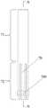
图1为本发明实施例1提供的桥塞坐封丢手适配器的纵向剖视图;1 is a longitudinal cross-sectional view of a bridge plug setting and throwing hand adapter provided in
图2为本发明实施例1提供的桥塞坐封丢手适配器省略推筒的纵向剖视图;Fig. 2 is the longitudinal cross-sectional view of the bridge plug setting and discarding hand adapter provided in
图3为本发明实施例1提供的弹性套的三维视图;3 is a three-dimensional view of the elastic sleeve provided in
图4为本发明实施例1提供的弹性套的正面视图;4 is a front view of the elastic sleeve provided in
图5为沿图4中A-A线的剖视图;Fig. 5 is a sectional view along line A-A in Fig. 4;
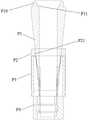
图6为本发明实施例2提供的桥塞的纵向剖视图;6 is a longitudinal cross-sectional view of a bridge plug provided in
图7为本发明实施例2提供的桥塞省略推环的纵向剖视图;7 is a longitudinal cross-sectional view of the bridge plug provided in
图8为本发明实施例2提供的桥塞坐封丢手适配器与桥塞的推环配合时的纵向剖视图;8 is a longitudinal cross-sectional view of the bridge plug setting and discarding hand adapter provided in
图9为本发明实施例2提供的桥塞坐封丢手适配器与桥塞配合时的纵向剖视图;9 is a longitudinal cross-sectional view of the bridge plug setting and discarding hand adapter provided in
图10为本发明实施例3提供的桥塞坐封丢手适配器与桥塞、坐封工具和外套管共同配合时桥塞锥体的外侧面与桥塞密封环的第二内锥面刚刚接触时的结构示意图;Fig. 10 shows that the outer side surface of the bridge plug cone is just in contact with the second inner cone surface of the bridge plug sealing ring when the bridge plug setting and throwing hand adapter provided in the third embodiment of the present invention cooperates with the bridge plug, the setting tool and the outer sleeve Schematic diagram of the time structure;
图11为本发明实施例3提供的桥塞坐封丢手适配器与桥塞、坐封工具和外套管共同配合时桥塞卡瓦紧贴于外套管的内壁时的结构示意图;11 is a schematic structural diagram of the bridge plug slips in close contact with the inner wall of the outer casing when the bridge plug setting and discarding adapter provided in
图12为本发明实施例3提供的桥塞坐封丢手适配器与桥塞、坐封工具和外套管共同配合时剪切销钉剪断后的结构示意图;12 is a schematic structural diagram of the shearing pin after the bridge plug setting and discarding adapter provided in
图13为本发明实施例3提供的桥塞坐封丢手适配器与桥塞、坐封工具和外套管共同配合时弹性套底端的环形外凸起快要脱离引鞋的内凹槽的结构示意图;13 is a schematic structural diagram showing that the annular outer protrusion at the bottom end of the elastic sleeve is about to separate from the inner groove of the shoe when the bridge plug setting and throwing hand adapter provided in
图14为本发明实施例3提供的桥塞坐封丢手适配器与桥塞、坐封工具和外套管共同配合时弹性套脱离时桥塞卡瓦和桥塞引鞋滞留外套管内的结构示意图。14 is a schematic structural diagram of the bridge plug slip and the bridge plug guide shoe remaining in the outer casing when the elastic sleeve is disengaged when the bridge plug setting and throwing hand adapter provided in
附图标记说明:Description of reference numbers:
1-推筒,2-拉杆,3-内剪切环,4-剪切销钉,5-外剪切套,6-调整环,1-Push cylinder, 2-Tie rod, 3-Inner shear ring, 4-Shear pin, 5-Outer shear sleeve, 6-Adjust ring,
7-弹性套,71-固定套部,710-内凸起,72-活动套部,70-弹性条,700-外凸起,7-elastic sleeve, 71-fixed sleeve, 710-inner protrusion, 72-movable sleeve, 70-elastic strip, 700-outer protrusion,
S1-坐封工具运动套,S2-坐封工具芯轴;S1-Setting tool movement sleeve, S2-Setting tool mandrel;
P1-桥塞推环,P10-桥塞内凸缘,P11-第一内锥面;P1-bridge plug push ring, P10-bridge plug inner flange, P11-first inner cone surface;
P2-桥塞密封环,P21-第二内锥面;P2-bridge plug sealing ring, P21-second inner cone surface;
P3-桥塞卡瓦,P4-桥塞引鞋;P3-bridge plug slip, P4-bridge plug guide shoe;
100-外套管。100 - Outer casing.
具体实施方式Detailed ways
以下实施例用于说明本发明,但不用来限制本发明的范围。The following examples are intended to illustrate the present invention, but not to limit the scope of the present invention.
本发明公开了一种桥塞坐封丢手适配器及其配套工具、使用方法,桥塞坐封丢手适配器与坐封工具、桥塞和外套管100配套使用,其中,拉杆2的上部于推筒1内对接坐封工具,弹性套7对接桥塞,当桥塞坐封丢手适配器置于外套管100内,推动坐封工具带动拉杆2向下运动,直至坐封力大于剪切销钉4的剪切力时剪切销钉4被剪断,实现桥塞于外套管100内的坐封;拉动坐封工具带动拉杆2向上运动,剪切销钉4随着拉杆2从弹性套7内抽出,弹性套7也随之脱离外套管100,最后使桥塞卡瓦P3和桥塞引鞋P4滞留外套管100内,完成丢手。本发明公开了一种桥塞坐封丢手适配器及其配套工具,不仅能完成完全坐封,保证密封效果,还能降低了丢手过程中的通井遇卡的风险。The invention discloses a bridge plug setting and discarding hand adapter, its supporting tool, and a method of use. The bridge plug setting and discarding hand adapter is used together with the setting tool, the bridge plug and the
实施例1:一种桥塞坐封丢手适配器Example 1: A bridge plug setting and throwing hand adapter
实施例1提供一种桥塞坐封丢手适配器,与坐封工具、桥塞和外套管100配套使用,下面结合附图对其结构进行详细描述。
参考图1,该桥塞坐封丢手适配器包括推筒1、拉杆2、内剪切环3、剪切销钉4、外剪切套5、调整环6和弹性套7,Referring to FIG. 1, the bridge plug setting and throwing hand adapter includes a
参考图2,内剪切环3、剪切销钉4、外剪切套5和弹性套7自上而下依次设置在拉杆2的外壁上。Referring to FIG. 2 , the
内剪切环3通过螺纹固定套在拉杆2的外壁上;The
外剪切套5活动设置在拉杆2的外侧,且内剪切环3与外剪切套5之间通过剪切销钉4固定连接;The
参考图3至图5,弹性套7包括固定套部71和活动套部72,所述活动套部72与所述固定套部71固定对接且一体成型;3 to 5 , the
所述弹性套7套在拉杆2上,且所述固定套部71的顶端伸入至所述外剪切套5内,弹性套7顶端的外壁与外剪切套5的内壁通过外螺纹连接;The
所述固定套部71内壁上设置有内凸起710,所述固定套部71的内凸起710紧抱在所述拉杆2的外壁上;An
所述活动套部72包括若干束弹性条70,若干束弹性条70环向间隔围成一个环形簇,每个弹性条70前端的外侧面设置有外凸起700;The
所述活动套部72的若干束弹性条70围绕在所述拉杆2的底端的外壁上。Several bundles of
继续参考图1和图2,调整环6上粗下细,呈中空的圆台形,调整环6套在弹性套7的固定套部71上。1 and 2 , the adjusting
拉杆2的上端穿设于推筒1内且拉杆2的底端伸出所述推筒1,调整环6恰好封堵推筒1底端与拉杆2外壁之间的环形空间,如图1所示。具体地,调整环6的内壁套在推筒1底端对应的弹性套7的固定套部71的外壁上,弹性套7的外壁与调整环6的内壁通过螺纹连接,推筒1底端的内壁套在调整环6的外壁上。The upper end of the
其中,拉杆2的上部于推筒1内对接坐封工具,弹性套7用于对接桥塞,当桥塞坐封丢手适配器置于外套管100内,推动坐封工具带动拉杆2向下运动,实现桥塞于外套管100内的坐封;拉动坐封工具带动拉杆2向上运动,直至坐封力大于所述剪切销钉4的剪切力时剪切销钉4被剪断,剪切销钉4随着拉杆2从弹性套7内抽出,弹性套7也随之脱离外套管100,最后使桥塞卡瓦P3和桥塞引鞋P4滞留外套管100内,完成丢手。Wherein, the upper part of the
实施例2:一种桥塞坐封丢手适配器的配套工具Embodiment 2: A kind of supporting tool for bridge plug setting and discarding hand adapter
实施例2提供一种桥塞坐封丢手适配器的配套工具,与实施例1的桥塞坐封丢手适配器相互配套使用,下面结合附图对其结构进行详细描述。
参考图10至图14,该桥塞坐封丢手适配器的配套工具包括坐封工具、桥塞和外套管100,Referring to Fig. 10 to Fig. 14 , the supporting tool of the bridge plug setting and discarding adapter includes a setting tool, a bridge plug and an
坐封工具的底端设置于推筒1顶端内且与拉杆2的顶端对接;The bottom end of the setting tool is arranged in the top end of the
外套管100套在坐封工具和桥塞坐封丢手适配器的外侧;The
桥塞坐封在桥塞坐封丢手适配器的弹性套7与外套管100之间的环形空间。The bridge plug is set in the annular space between the
具体地,坐封工具包括坐封工具运动套S1和坐封工具芯轴S2,Specifically, the setting tool includes a setting tool movement sleeve S1 and a setting tool mandrel S2,
坐封工具运动套S1的底端内壁边缘向外延伸形成坐封工具内凸缘,所述坐封工具芯轴S2顶端的外壁固定套设在坐封工具运动套S1的坐封工具内凸缘的内壁,推筒1顶端的内壁与坐封工具运动套S1的坐封工具内凸缘的外壁通过螺纹固定连接;The bottom end inner wall edge of the setting tool moving sleeve S1 extends outward to form the setting tool inner flange, and the outer wall of the top end of the setting tool mandrel S2 is fixedly sleeved on the setting tool inner flange of the setting tool moving sleeve S1 The inner wall of the top of the
坐封工具芯轴S2的底端的端面设置有拉杆槽,拉杆2的顶端设置于坐封工具芯轴S2的拉杆槽内,并与拉杆槽的内壁通过螺纹固定连接,由此实现坐封工具的底端设置于推筒1顶端内且与拉杆2的顶端对接。The end face of the bottom end of the setting tool mandrel S2 is provided with a tie rod groove, and the top end of the
参考图6至图9,桥塞包括桥塞锥体P1、桥塞密封环P2、桥塞卡瓦P3、桥塞引鞋P4,6 to 9, the bridge plug includes a bridge plug cone P1, a bridge plug sealing ring P2, a bridge plug slip P3, and a bridge plug guide shoe P4,
桥塞锥体P1上大下小,呈中空的圆台形;The bridge plug cone P1 is large on the top and small on the bottom, in the shape of a hollow truncated cone;
桥塞锥体P1顶端的内壁边缘向外延伸形成桥塞内凸缘P10,推筒1底端的外壁边缘向外延伸形成外凸缘,所述推筒1的外凸缘紧套在桥塞锥体P1的桥塞内凸缘P10的外壁上;The inner wall edge of the top end of the bridge plug cone P1 extends outward to form a bridge plug inner flange P10, and the outer wall edge of the bottom end of the
桥塞锥体P1顶端的桥塞内凸缘的内壁设置为第一内锥面P11,调整环6的外侧面设置为外锥面,且桥塞锥体P1的第一内锥面P11与调整环6的外锥面相适配,桥塞锥体P1的第一内锥面P11固定套在调整环6的外锥面上;The inner wall of the inner flange of the bridge plug at the top of the bridge plug cone P1 is set as the first inner cone surface P11, the outer surface of the
桥塞密封环P2的内壁上端大、下端小,桥塞密封环P2的内壁设置为第二内锥面P21,且桥塞密封环P2的第二内锥面P21与桥塞锥体P1的外侧面相互适配,桥塞密封环P2的第二内锥面P21套设在桥塞锥体P1的外侧面上;The upper end of the inner wall of the bridge plug sealing ring P2 is large and the lower end is small. The sides are adapted to each other, and the second inner cone surface P21 of the bridge plug sealing ring P2 is sleeved on the outer side surface of the bridge plug cone P1;
引鞋P4的内壁设置有内凹槽,弹性套7的若干束弹性条70的外凸起700环绕形成环形外凸起,引鞋4的内凹槽套在弹性套7底端的环形外凸起上;The inner wall of the shoe guide P4 is provided with an inner groove, the
桥塞卡瓦P3的两端分别固定连接与所述桥塞密封环P2和引鞋P4的端面。Two ends of the bridge plug slip P3 are respectively fixedly connected to the end faces of the bridge plug sealing ring P2 and the guide shoe P4.
桥塞锥体P1、桥塞密封环P2、桥塞卡瓦P3和桥塞引鞋P4从上至下依次对接构成所述桥塞,实现对弹性套7与外套管100之间的环形空间的坐封。The bridge plug cone P1, the bridge plug sealing ring P2, the bridge plug slips P3 and the bridge plug guide shoes P4 are connected in sequence from top to bottom to form the bridge plug, so as to realize the connection of the annular space between the
优选地,为了提高桥塞坐封在弹性套7与外套管100之间的环形空间的紧密性,桥塞卡瓦P3的外壁设置有锯齿,且该锯齿为V形齿。Preferably, in order to improve the tightness of the bridge plug setting in the annular space between the
实施例3:一种桥塞坐封丢手适配器与其配套工具配合的使用方法Embodiment 3: A method of using the bridge plug setting and discarding hand adapter and its supporting tool
实施例3提供一种桥塞的丢手方法,需要实施例1的桥塞坐封丢手适配器和实施例2的桥塞坐封丢手适配器的配套工具配合使用,该方法包括以下步骤:
步骤S1:桥塞锥体P1套设在弹性套7的外侧,如图8所示;Step S1: the bridge plug cone P1 is sleeved on the outer side of the
步骤S2:引鞋P4的内凹槽套在弹性套7底端的环形外凸起上,如图9所示;Step S2: the inner groove of the shoe P4 is sleeved on the annular outer protrusion at the bottom end of the
步骤S3:向下推动坐封工具运动套S1,带动推筒1和坐封工具芯轴S2向下移动,同时坐封工具芯轴S2推动拉杆2向下移动,直至推筒1的底端的外凸缘套设在桥塞锥体P1的桥塞内凸缘P10的外壁上;Step S3: Push the setting tool moving sleeve S1 downward to drive the
步骤S4:继续向下推动坐封工具运动套S1,坐封工具芯轴S2随之向下运动,直至调整环6的外锥面与桥塞锥体P1的第一内锥面P11固定套接;Step S4: Continue to push the setting tool moving sleeve S1 downward, and the setting tool mandrel S2 moves downward accordingly until the outer conical surface of the adjusting
步骤S5:继续向下推动坐封工具运动套S1,桥塞锥体P1的外侧面紧贴于桥塞密封环P2的第二内锥面P21,如图10所示;Step S5: Continue to push the setting tool moving sleeve S1 downward, and the outer side surface of the bridge plug cone P1 is in close contact with the second inner cone surface P21 of the bridge plug sealing ring P2, as shown in Figure 10;
步骤S6:继续向下推动坐封工具运动套S1,桥塞锥体P1受到上方的挤压被迫向下延伸,同时向外胀开桥塞密封环P2和桥塞卡瓦P3,直至桥塞卡瓦P3紧贴于外套管100的内壁,直至桥塞在弹性套7与外套管100之间的环形空间完成坐封,如图11所示;Step S6: Continue to push the setting tool moving sleeve S1 downward, the bridge plug cone P1 is forced to extend downward by being squeezed from above, and at the same time, the bridge plug sealing ring P2 and the bridge plug slips P3 are expanded outward until the bridge plug is pressed. The slips P3 are in close contact with the inner wall of the
步骤S7:继续向下推动坐封工具运动套S1增加坐封力,直至坐封力达到剪切销钉4的剪切力,剪切销钉4被剪断,如图12所示;Step S7: Continue to push down the setting tool movement sleeve S1 to increase the setting force, until the setting force reaches the shear force of the
步骤S8:向上提拉坐封工具芯轴S2,带动拉杆2向上移动,内剪切套3随之向上移动,同时外剪切套5也随着拉杆2向上运动,直至拉杆2的底端端面离开弹性套7的固定套部71的内凸起710环绕形成的环形外凸起;Step S8: Pull up the mandrel S2 of the setting tool, drive the
步骤S9:向上提拉坐封工具芯轴S2,拉杆2从弹性套7的活动套部72的若干束弹性条70围成的环形簇抽取,活动套部72失去内部支撑而向引鞋4的内凹槽收缩,如图13所示;Step S9: Pull up the setting tool mandrel S2, the
步骤S10:弹性套7随着拉杆2向上移动,弹性套7底端端面的环形外凸起与桥塞引鞋P4的内凹槽抽出,直至弹性套7桥塞锥体P1完全脱离,最后使桥塞卡瓦P3和桥塞引鞋P4滞留外套管100内,完成丢手,如图14所示。Step S10: The
虽然,上文中已经用一般性说明及具体实施例对本发明作了详尽的描述,但在本发明基础上,可以对之作一些修改或改进,这对本领域技术人员而言是显而易见的。因此,在不偏离本发明精神的基础上所做的这些修改或改进,均属于本发明要求保护的范围。Although the present invention has been described in detail above with general description and specific embodiments, some modifications or improvements can be made on the basis of the present invention, which will be obvious to those skilled in the art. Therefore, these modifications or improvements made without departing from the spirit of the present invention fall within the scope of the claimed protection of the present invention.
最后应说明的是:以上实施例仅用以说明本发明的技术方案,而非对其限制;尽管参照前述实施例对本发明进行了详细的说明,本领域的普通技术人员应当理解:其依然可以对前述各实施例所记载的技术方案进行修改,或者对其中部分技术特征进行等同替换;而这些修改或者替换,并不使相应技术方案的本质脱离本发明各实施例技术方案的精神和范围。Finally, it should be noted that the above embodiments are only used to illustrate the technical solutions of the present invention, but not to limit them; although the present invention has been described in detail with reference to the foregoing embodiments, those of ordinary skill in the art should understand that it can still be The technical solutions described in the foregoing embodiments are modified, or some technical features thereof are equivalently replaced; and these modifications or replacements do not make the essence of the corresponding technical solutions deviate from the spirit and scope of the technical solutions of the embodiments of the present invention.
Claims (7)
Priority Applications (1)
| Application Number | Priority Date | Filing Date | Title |
|---|---|---|---|
| CN202210727704.3ACN115075743A (en) | 2022-06-23 | 2022-06-23 | Bridge plug setting releasing adapter and matched tool and using method thereof |
Applications Claiming Priority (1)
| Application Number | Priority Date | Filing Date | Title |
|---|---|---|---|
| CN202210727704.3ACN115075743A (en) | 2022-06-23 | 2022-06-23 | Bridge plug setting releasing adapter and matched tool and using method thereof |
Publications (1)
| Publication Number | Publication Date |
|---|---|
| CN115075743Atrue CN115075743A (en) | 2022-09-20 |
Family
ID=83254890
Family Applications (1)
| Application Number | Title | Priority Date | Filing Date |
|---|---|---|---|
| CN202210727704.3APendingCN115075743A (en) | 2022-06-23 | 2022-06-23 | Bridge plug setting releasing adapter and matched tool and using method thereof |
Country Status (1)
| Country | Link |
|---|---|
| CN (1) | CN115075743A (en) |
Cited By (1)
| Publication number | Priority date | Publication date | Assignee | Title |
|---|---|---|---|---|
| CN115749627A (en)* | 2022-12-04 | 2023-03-07 | 德州景美石油机械有限公司 | Downhole tool with high-temperature trigger type sliding sleeve |
Citations (6)
| Publication number | Priority date | Publication date | Assignee | Title |
|---|---|---|---|---|
| US4773478A (en)* | 1987-05-27 | 1988-09-27 | Halliburton Company | Hydraulic setting tool |
| CN2864080Y (en)* | 2005-10-31 | 2007-01-31 | 新疆石油管理局钻井工艺研究院 | Hydraulic releasing tool |
| CN104863540A (en)* | 2015-05-28 | 2015-08-26 | 荆州市赛瑞能源技术有限公司 | Anchor packer with hydraulic setting function and rotation unsetting function |
| CN107255023A (en)* | 2017-08-18 | 2017-10-17 | 中国石油集团川庆钻探工程有限公司 | Large-drift-diameter drilling-free bridge plug with setting releasing function |
| CN108716379A (en)* | 2018-07-25 | 2018-10-30 | 百勤能源科技(惠州)有限公司 | A kind of solvable bridge plug of big orifice |
| CN113738296A (en)* | 2021-09-18 | 2021-12-03 | 中国石油化工股份有限公司 | Bridge plug adapter |
- 2022
- 2022-06-23CNCN202210727704.3Apatent/CN115075743A/enactivePending
Patent Citations (6)
| Publication number | Priority date | Publication date | Assignee | Title |
|---|---|---|---|---|
| US4773478A (en)* | 1987-05-27 | 1988-09-27 | Halliburton Company | Hydraulic setting tool |
| CN2864080Y (en)* | 2005-10-31 | 2007-01-31 | 新疆石油管理局钻井工艺研究院 | Hydraulic releasing tool |
| CN104863540A (en)* | 2015-05-28 | 2015-08-26 | 荆州市赛瑞能源技术有限公司 | Anchor packer with hydraulic setting function and rotation unsetting function |
| CN107255023A (en)* | 2017-08-18 | 2017-10-17 | 中国石油集团川庆钻探工程有限公司 | Large-drift-diameter drilling-free bridge plug with setting releasing function |
| CN108716379A (en)* | 2018-07-25 | 2018-10-30 | 百勤能源科技(惠州)有限公司 | A kind of solvable bridge plug of big orifice |
| CN113738296A (en)* | 2021-09-18 | 2021-12-03 | 中国石油化工股份有限公司 | Bridge plug adapter |
Non-Patent Citations (1)
| Title |
|---|
| 蔺伟, 李颖, 陈宁, 逯梅, 贾广武: "一种新型可取式桥塞的研制与应用", 石油矿场机械, no. 06, 30 November 2003 (2003-11-30), pages 83 - 85* |
Cited By (1)
| Publication number | Priority date | Publication date | Assignee | Title |
|---|---|---|---|---|
| CN115749627A (en)* | 2022-12-04 | 2023-03-07 | 德州景美石油机械有限公司 | Downhole tool with high-temperature trigger type sliding sleeve |
Similar Documents
| Publication | Publication Date | Title |
|---|---|---|
| CN108343395A (en) | A kind of single deck tape-recorder watt big orifice exempts to bore mill composite bridge plug and its sets method | |
| EP2150682B1 (en) | Downhole tubular expansion tool and method | |
| WO2011031164A1 (en) | Well tool and method for severing and withdrawing a pipe section from a pipe string in a well | |
| CN106481308A (en) | Temporary plugging large-diameter bridge plug and production tubing running method | |
| CN115075743A (en) | Bridge plug setting releasing adapter and matched tool and using method thereof | |
| CN111075394A (en) | Controllable dissolving mechanism of downhole tool and use method thereof | |
| CN206280047U (en) | Temporary blocking type large diameter bridge plug | |
| CN117449797A (en) | Unpackable packing device, lifting unpacking tool and application | |
| CN111502575B (en) | Hydraulic pressure starts formula packer deblocking instrument | |
| CN210134891U (en) | Safety joint for sand-proof screen pipe and sand-proof screen pipe | |
| CN115263229B (en) | Sealing packer capable of being inserted backwards and using method thereof | |
| CN103758476B (en) | Non-cementing expansion type liner hanger | |
| CN114293942B (en) | Milling and cutting integrated device for coiled tubing salvaging sleeve | |
| CN215672111U (en) | A salvage and wash integrated instrument for retrieving easy sand setting well anchoring device | |
| CN210068041U (en) | Straight well screen pipe fishing spear | |
| CN212054620U (en) | Controllable dissolving mechanism of downhole tool | |
| CN103821472A (en) | Fishing bottom plug and fishing tool for expansion pipe | |
| CN209413877U (en) | An oil and gas well subsidy pipe pulling device | |
| WO2023097570A1 (en) | Fracturing device and fracturing method for preset ball | |
| CN106677738A (en) | Soluble packer | |
| CN112682017B (en) | Underground fracturing tool | |
| CN105649568A (en) | Hydraulic wellhead hanger and self-spraying rotary machine integrated assembly | |
| CN213116252U (en) | Recyclable packer | |
| CN212296285U (en) | Sleeve milling overshot | |
| CN222478689U (en) | A retractable coiled tubing falling object milling and salvage integrated tool |
Legal Events
| Date | Code | Title | Description |
|---|---|---|---|
| PB01 | Publication | ||
| PB01 | Publication | ||
| SE01 | Entry into force of request for substantive examination | ||
| SE01 | Entry into force of request for substantive examination |