CN115066335A - Capping station with positioning mechanism - Google Patents
Capping station with positioning mechanismDownload PDFInfo
- Publication number
- CN115066335A CN115066335ACN202080096995.XACN202080096995ACN115066335ACN 115066335 ACN115066335 ACN 115066335ACN 202080096995 ACN202080096995 ACN 202080096995ACN 115066335 ACN115066335 ACN 115066335A
- Authority
- CN
- China
- Prior art keywords
- cover
- printhead
- bracket
- capping station
- printing
- Prior art date
- Legal status (The legal status is an assumption and is not a legal conclusion. Google has not performed a legal analysis and makes no representation as to the accuracy of the status listed.)
- Pending
Links
- 230000007246mechanismEffects0.000titleclaimsabstractdescription42
- 238000007639printingMethods0.000claimsabstractdescription97
- 238000007789sealingMethods0.000claimsabstractdescription4
- 238000000034methodMethods0.000claimsdescription13
- 239000003795chemical substances by applicationSubstances0.000description31
- 230000003287optical effectEffects0.000description11
- 238000006073displacement reactionMethods0.000description6
- 239000000463materialSubstances0.000description4
- 238000003825pressingMethods0.000description4
- 239000000123paperSubstances0.000description3
- 230000008569processEffects0.000description3
- 230000008859changeEffects0.000description2
- 239000000356contaminantSubstances0.000description2
- 238000010586diagramMethods0.000description2
- 238000001035dryingMethods0.000description2
- 239000004033plasticSubstances0.000description2
- 238000011144upstream manufacturingMethods0.000description2
- 229910000831SteelInorganic materials0.000description1
- -1card stockSubstances0.000description1
- 238000006243chemical reactionMethods0.000description1
- 238000011109contaminationMethods0.000description1
- 230000007423decreaseEffects0.000description1
- 238000000151depositionMethods0.000description1
- 239000000428dustSubstances0.000description1
- 239000012530fluidSubstances0.000description1
- 239000002783friction materialSubstances0.000description1
- 238000010438heat treatmentMethods0.000description1
- 238000007641inkjet printingMethods0.000description1
- 238000012986modificationMethods0.000description1
- 230000004048modificationEffects0.000description1
- 230000001681protective effectEffects0.000description1
- 230000009467reductionEffects0.000description1
- 230000003068static effectEffects0.000description1
- 239000010959steelSubstances0.000description1
- 230000002195synergetic effectEffects0.000description1
- 239000004753textileSubstances0.000description1
- 230000007704transitionEffects0.000description1
- 238000009834vaporizationMethods0.000description1
- 230000008016vaporizationEffects0.000description1
Images


Classifications
- B—PERFORMING OPERATIONS; TRANSPORTING
- B41—PRINTING; LINING MACHINES; TYPEWRITERS; STAMPS
- B41J—TYPEWRITERS; SELECTIVE PRINTING MECHANISMS, i.e. MECHANISMS PRINTING OTHERWISE THAN FROM A FORME; CORRECTION OF TYPOGRAPHICAL ERRORS
- B41J2/00—Typewriters or selective printing mechanisms characterised by the printing or marking process for which they are designed
- B41J2/005—Typewriters or selective printing mechanisms characterised by the printing or marking process for which they are designed characterised by bringing liquid or particles selectively into contact with a printing material
- B41J2/01—Ink jet
- B41J2/135—Nozzles
- B41J2/165—Prevention or detection of nozzle clogging, e.g. cleaning, capping or moistening for nozzles
- B41J2/16505—Caps, spittoons or covers for cleaning or preventing drying out
- B41J2/16508—Caps, spittoons or covers for cleaning or preventing drying out connected with the printer frame
- B41J2/16511—Constructions for cap positioning
Landscapes
- Ink Jet (AREA)
Abstract
Translated fromChinese
Description
Translated fromChinese背景技术Background technique
打印系统可以包括具有多个喷嘴的打印头或笔,所述喷嘴将打印剂输送到打印介质上以便打印图像。打印系统可以包括加盖站,以密封打印头的喷嘴,使其在非打印时段期间免受污染物和干燥的影响。A printing system may include a printhead or pen having a plurality of nozzles that deliver printing agent onto a print medium for printing an image. The printing system may include a capping station to seal the nozzles of the printhead from contamination and drying during non-printing periods.
附图说明Description of drawings
结合附图,从下面的详细描述中,各种示例特征将是明显的,附图中:Various example features will be apparent from the following detailed description, taken in conjunction with the accompanying drawings, in which:
图1示意性地示出了根据本公开的示例的打印系统;FIG. 1 schematically illustrates a printing system according to an example of the present disclosure;
图2a和2b分别示出了根据本公开的示例的具有处于第一盖位置和第二盖位置的盖的加盖站;Figures 2a and 2b illustrate a capping station with a cap in a first cap position and a second cap position, respectively, according to an example of the present disclosure;
图3a和3b分别示出了根据本公开的示例的锁定到引导通道并且滑动跨过引导通道的盖托架的截面视图;Figures 3a and 3b respectively show cross-sectional views of a cover bracket locked to and slid across a guide channel according to an example of the present disclosure;
图4a-4c示出了根据本公开的示例的在若干位置处具有盖的加盖站;Figures 4a-4c illustrate a capping station with covers at several locations, according to an example of the present disclosure;
图5示出了根据本公开的示例的盖托架和传感器的顶视图;5 shows a top view of a cover bracket and sensor according to an example of the present disclosure;
图6示意性地示出了根据本公开的示例的打印系统;并且FIG. 6 schematically illustrates a printing system according to an example of the present disclosure; and
图7是根据本公开的示例的用于为打印系统的打印头加盖的方法的示例的框图。7 is a block diagram of an example of a method for capping a printhead of a printing system according to an example of the present disclosure.
具体实施方式Detailed ways
图1示意性地示出了根据本公开的示例的打印系统。打印系统100包括用于在打印介质前进方向111上输送打印介质110的打印介质前进系统(图1中未示出)和支撑打印头130以将打印剂输送到打印介质110上的打印头支撑件120。FIG. 1 schematically illustrates a printing system according to an example of the present disclosure.
打印头130可以设置有多个喷嘴,以将例如墨的打印剂输送到打印介质110上,从而打印图像。在打印期间,打印剂的点可以被精确地输送到打印介质110上。在本公开中,在打印介质上输送打印剂包括将打印剂喷射、喷出、吐出或以其他方式沉积到打印介质上。打印头可以包括打印剂室,其容纳将要被输送到打印介质上的打印剂。The
在一些示例中,加热元件可以引起打印剂室中的打印剂的快速气化,从而增加该打印剂室内的内部压力。这种压力的增加使得打印剂的液滴通过喷嘴从打印剂室离开到打印介质。这些打印系统可以被称为热喷墨打印系统。In some examples, the heating element may cause rapid vaporization of the printing agent in the printing agent chamber, thereby increasing the internal pressure within the printing agent chamber. This increase in pressure causes droplets of print agent to exit from the print agent chamber through the nozzle to the print medium. These printing systems may be referred to as thermal inkjet printing systems.
在一些示例中,压电元件可以用于迫使打印剂的液滴通过喷嘴从打印剂室输送到打印介质上。可以向压电元件施加电压,这可以改变其形状。这种形状的改变可以迫使打印剂的液滴通过喷嘴离开。这些打印系统可以被称为压电打印系统。In some examples, piezoelectric elements may be used to force droplets of print agent to be delivered from the print agent chamber through the nozzle onto the print medium. A voltage can be applied to the piezoelectric element, which can change its shape. This change in shape can force the droplets of printing agent to exit through the nozzle. These printing systems may be referred to as piezoelectric printing systems.
在图1的示例中,打印头支撑件120支撑若干打印头130,例如八个打印头。该示例的打印头支撑件120包括托架,用于使打印头移动跨过扫描轴线121。该图的打印头可以重复地行进跨过扫描轴线121,以将打印剂输送到打印介质110上,该打印介质110可以沿着打印介质前进方向111前进。扫描轴线121可以基本垂直于打印介质前进方向111。扫描轴线可以基本平行于打印介质宽度方向。在一些示例中,四个打印头可以安装在单个打印头支撑件上。在一些示例中,单个打印头可以安装在打印头支撑件上。In the example of FIG. 1, the
在一些示例中,打印头支撑件可以是静态的。打印头支撑件可以包括打印杆。打印杆可以沿着打印介质的宽度延伸。打印杆可以包括一个或多个打印头。多个喷嘴可以沿着打印介质的宽度分布在所述一个或多个打印头内。打印杆的宽度可以基本垂直于打印介质前进方向。这种布置可以允许同时对打印介质的大部分宽度进行打印。这些打印机系统可以被称为页宽阵列(PWA)打印机系统。In some examples, the printhead support may be static. The printhead support may include a printbar. The print bars may extend along the width of the print media. A printbar may include one or more printheads. A plurality of nozzles may be distributed within the one or more printheads along the width of the print medium. The width of the print bar may be substantially perpendicular to the direction of advance of the print medium. Such an arrangement may allow most of the width of the print medium to be printed simultaneously. These printer systems may be referred to as page-wide array (PWA) printer systems.
打印介质110可以沿着打印介质前进方向111前进或移动。打印介质可以由前进系统(图1中未示出)移动。前进系统可以包括辊、带系统和/或轮。打印介质110可以是将要在打印系统中使用的任何形状或尺寸。在一些示例中,前进系统可以包括用于将打印介质进给到打印区的打印介质进给机构。The
在一些示例中,前进系统可以包括打印介质支撑件,以支撑打印介质,以接收由打印头输送的打印剂。打印介质支撑件可在打印期间在打印区中引导和支撑打印介质。In some examples, the advancement system may include a print media support to support the print media to receive printing agent delivered by the printhead. The print media support may guide and support the print media in the print zone during printing.
打印介质是能够接收打印剂(例如墨)的材料。打印介质可以包括纸、纸板、卡片纸、纺织材料或塑料材料。打印介质可以是片材,例如纸片材或纸板片材。A print medium is a material capable of receiving a printing agent, such as ink. Print media may include paper, cardboard, card stock, textile materials, or plastic materials. The print medium may be a sheet, such as a paper sheet or a cardboard sheet.
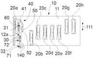
该图的打印系统100包括加盖站10,加盖站10包括一系列盖,例如用于每个打印头的盖,其中,盖20用于密封打印头,以及包括定位机构,其用于在第一盖位置和第二盖位置之间移动盖20。该盖可以移位以接合打印头。加盖站可密封打印头以防止流体流过打印头并且防止打印剂在喷嘴内干燥。因此,喷嘴可以保持健康并且准备好打印。当打印操作不在进行时,盖可以接合打印头。当打印操作将要开始时,盖或打印头可以移动以解除打印头的密封。The
加盖站可以包括用于支撑盖的盖托架。定位机构可以使盖托架在引导通道上沿平行于打印介质前进方向的方向在第一盖位置和第二盖位置之间滑动,并且可以选择性地将盖托架锁定在第一盖位置和第二盖位置。The capping station may include a cap bracket for supporting the cap. The positioning mechanism can slide the cover carriage on the guide channel between a first cover position and a second cover position in a direction parallel to the direction of advance of the print medium, and can selectively lock the cover carriage in the first cover position and the second cover position. Second cover position.
在该示例中,加盖站10包括多个盖以密封安装在打印头支撑件130上的打印头130。在该图中,加盖站10包括八个盖以密封八个打印头。在该图中,盖20可以沿平行于打印介质前进方向111的方向移动。In this example,
在一些示例中,来自加盖站的多个盖的盖20可以沿平行于打印介质前进方向111的方向移动。在本公开中,安装在可沿平行于打印介质前进方向111的方向移动的盖托架中的盖可以被称为可移动盖或可滑动盖。其余的盖可以保持在固定位置。这些盖可以被称为固定盖。在一些示例中,若干盖(例如两个盖)可以沿平行于打印介质前进方向的方向移动以密封打印头。在一些示例中,多个盖可以沿平行于打印介质前进方向的方向移位以将盖定位在由打印头支撑件支撑的打印头下方。In some examples, the
在一些示例中,打印系统可以包括移位构件,以使打印头支撑件和加盖站中的一个相对于打印头支撑件和加盖站中的另一个移动。In some examples, the printing system may include a displacement member to move one of the printhead support and the capping station relative to the other of the printhead support and the capping station.
在一些示例中,移位构件可以使打印头支撑件朝向加盖站移动以对准盖和打印头,例如,将打印头定位在盖上方。打印头支撑件可以包括托架,用于使打印头跨过扫描轴线朝向加盖站移动。移位构件可以包括打印头支撑件的托架。在该示例中,打印头支撑件120可以跨过扫描轴线121朝向加盖站移位。打印头支撑件120因此可以将打印头定位在加盖站上方。加盖站的盖因此可以接合打印头。打印头的喷嘴因此可以被密封。In some examples, the displacement member may move the printhead support toward the capping station to align the cap and the printhead, eg, to position the printhead over the cap. The printhead support may include a carriage for moving the printhead across the scan axis towards the capping station. The displacement member may comprise a carriage of the printhead support. In this example, the
在一些示例中,移位构件可以使加盖站朝向打印头支撑件移动以使盖和打印头对准。在页宽阵列打印机系统中,加盖站可以朝向打印杆移动。例如,打印杆可以从打印区缩回,并且加盖站可以朝向处于缩回位置的打印杆旋转。In some examples, the displacement member may move the capping station toward the printhead support to align the cap and the printhead. In a page width array printer system, the capping station can be moved towards the print bar. For example, the print bar can be retracted from the print zone and the capping station can be rotated towards the print bar in the retracted position.
该图的打印系统包括安装在打印头支撑件120处的传感器系统140。因此,该图的传感器系统可以与打印头支撑件一起朝向加盖站移动。传感器系统140可以检测盖20的位置。在一些示例中,用于检测盖沿打印介质前进方向的位置的传感器系统可以安装在加盖站处。例如,加盖站可以包括开关以检测盖的位置。The printing system of this figure includes a
图2a和2b分别示出了根据本公开的示例的具有处于第一盖位置和处于第二盖位置的盖的加盖站。这些图示出了用于打印系统的加盖站10,其包括用于密封打印头的盖20a和用于支撑盖20a的盖托架30。在这些图中,加盖站10还包括定位机构40,以使盖托架30在引导通道50上沿平行于打印介质前进方向111的方向在第一盖位置(图2a)和第二盖位置(图2b)之间滑动,并且选择性地将盖托架30锁定在第一盖位置和第二盖位置。盖托架和盖因此可以一起移动跨过引导通道。2a and 2b illustrate a capping station with a cover in a first cover position and a second cover position, respectively, according to an example of the present disclosure. These figures show a
因此,盖20a可以以紧凑且简单的方式定位在沿平行于打印介质前进方向111的方向的若干位置处。因此,具有若干位置的打印头可以用盖20A密封。由于盖托架可沿着引导通道滑动,所以可限制沿垂直于打印介质前进方向的方向的移动。因此,可以提高盖的位置的精度。Therefore, the
这些图中的加盖站10包括多个盖20a-h。在该示例中,盖20b-h联接到加盖站10的支撑板11。盖20b-h可以装配在支撑板11的开口中。例如,盖20b-h可以卡扣到这些开口中。然而,盖20a可以沿着支撑板11的开口12a移动。在一些示例中,多个盖可以沿平行于打印介质前进方向的方向移动。因此,盖20a可以是可移动盖或可滑动盖,并且盖20b-h可以是固定盖。The
在这些图中,定位机构包括锁定机构60,以将盖托架30可滑动地联接到引导通道50。锁定机构60可将盖托架30锁定在第一盖位置(图2a)或第二盖位置(图2b)。锁定机构60可允许盖托架30沿引导通道50滑动。In these figures, the positioning mechanism includes a
在一些示例中,锁定机构可以包括锁定元件,该锁定元件能够在锁定位置和滑动位置之间移动,在锁定位置,锁定元件接合引导通道以将盖托架锁定到引导通道,在滑动位置,锁定元件在引导通道上滑动。In some examples, the locking mechanism may include a locking element moveable between a locking position in which the locking element engages the guide channel to lock the cover bracket to the guide channel and a sliding position in which the locking element locks The element slides on the guide channel.
在该示例中,盖托架30包括支架31。盖托架可包括接收盖的基部和从基部朝向引导通道延伸的支架。锁定机构可以联接到支架。锁定元件可以相对于支架移位,例如在锁定位置和滑动位置之间移位。In this example, the
该示例的定位机构40包括沿平行于打印介质前进方向111的方向延伸的引导杆41,其与支架31接合以引导盖托架30。引导杆41可以附接(例如紧固)到支撑板11。因此,可以防止盖托架的不对准。因此,盖可以精确地移动跨过引导通道并且定位在预定位置处,例如,在第一盖位置处或在第二盖位置处。引导杆可以引导盖托架,例如支架。例如,从支架突出的销可以沿着形成在引导杆中的凹槽滑动。The
在一些示例中,支架可以包括部分地包围引导杆的U形梁。引导杆可以包括基本对应于U形梁的形状。例如,引导杆可以包括矩形截面以接合U形梁。U形梁可以包括部分地包围引导杆的基部和一对侧壁。U形梁因此可以覆盖引导杆。这可以在打印头位于盖上方时保护引导杆免受灰尘和打印剂的影响。在一些示例中,U形梁因此可以沿着引导杆滑动。In some examples, the bracket may include a U-shaped beam that partially surrounds the guide rod. The guide rod may comprise a shape substantially corresponding to a U-shaped beam. For example, the guide rod may comprise a rectangular cross-section to engage the U-beam. The U-beam may include a base that partially surrounds the guide rod and a pair of side walls. The U-beam can thus cover the guide rod. This protects the guide bars from dust and ink when the print head is over the cover. In some examples, the U-beam can thus slide along the guide rod.
在这些图中,引导通道50包括在第一端到第二端之间延伸的长度。引导通道可以包括垂直于该长度延伸的宽度。引导通道可以包括多个接收器,以容纳用于将盖托架锁定在预定位置的锁定机构的锁定元件。在这些图中,引导通道50包括第一接收器51和第二接收器52。在图2a中,锁定元件装配到第一接收器51中以将盖托架30锁定在第一盖位置。在图2b中,锁定元件装配到第二接收器52中以将盖托架30锁定在第二盖位置。在这些示例中,第一接收器51在引导通道的第一端,并且第二接收器52在引导通道的第二端。第一接收器51和第二接收器52可以包括比引导通道的宽度更大的宽度。接收器可以是基本圆形的。在一些示例中,宽度可以沿着引导通道的长度是基本恒定的。In these figures, the
在这些图中,引导通道50附接到支撑板11,例如引导通道卡扣到支撑板的凹槽中。支撑板和引导通道可以由不同的材料制成。引导通道可以包括低摩擦材料以减小摩擦阻力。例如,支撑板可以包括钢,并且引导通道可以包括塑料。In these figures, the
在一些示例中,引导通道可以被穿孔到支撑板中。因此,引导通道可以集成在支撑板内。In some examples, the guide channel may be perforated into the support plate. Thus, the guide channel can be integrated in the support plate.
在这些图中,盖托架30包括第一识别特征71和第二识别特征72,以分别指示盖托架处于第一盖位置或第二盖位置。这些图的盖托架30包括沿平行于打印介质前进方向的方向延伸的盖托架杆32,其包括第一识别特征71和第二识别特征72。在这些示例中,第一识别特征71包括开口,并且第二识别特征72包括一对开口。In these figures, the
在一些示例中,盖托架杆可以从支架延伸。例如,盖托架杆可以从支架的U形梁延伸。盖托架杆可以包括U形。在一些示例中,盖托架杆的一部分可以由附接到支撑板的引导杆引导。In some examples, the cover bracket rods can extend from the brackets. For example, the cover bracket rods may extend from the U-beams of the brackets. The cover bracket rod may comprise a U-shape. In some examples, a portion of the cover bracket rod may be guided by a guide rod attached to the support plate.
传感器140可以检测这些识别特征。第一识别特征71可以与第一盖位置(图2a)相关联,并且第二识别特征72可以与第二盖位置(图2b)相关联。因此,当传感器140检测到第一识别特征71时,可确定第一盖位置。当传感器140检测到第二识别特征72时,可确定第二盖位置。
在这些图中,传感器140在包括识别特征的盖托架杆32上方。例如,传感器可以例如通过传感器支撑结构附接到加盖站10的支撑板11。在一些示例中,传感器可以在盖托架杆的下方或在盖托架杆的侧面处。在一些示例中,传感器可以安装在打印头支撑件处。In these figures, the
在一些示例中,传感器可以是图像传感器,例如相机。在一些示例中,传感器可以包括光学传感器。光学传感器可以包括发射器和接收器。发射器可以包括光源以照射盖托架杆。In some examples, the sensor may be an image sensor, such as a camera. In some examples, the sensor may comprise an optical sensor. Optical sensors may include transmitters and receivers. The emitter may include a light source to illuminate the cover carrier rod.
在一些示例中,光学传感器可以包括在盖托架杆的相对侧处的光源和接收器。光源可以将光束投射到接收器上。例如,光源可以在盖托架杆上方,并且接收器在盖托架杆下方。盖托架杆和光学传感器可以相对于彼此移动。由接收器接收的光可以根据它们之间的元件而变化。因此,当具有开口的第一识别特征位于光源和接收器之间时,由接收器接收的光可以不同于当具有一对开口的第二识别特征位于光源和接收器之间时。In some examples, the optical sensor may include a light source and a receiver at opposite sides of the cover bracket rod. A light source can project a light beam onto a receiver. For example, the light source may be above the cover bracket bar and the receiver below the cover bracket bar. The cover carrier rod and the optical sensor can move relative to each other. The light received by the receivers can vary depending on the elements between them. Thus, when the first identification feature having an opening is located between the light source and the receiver, the light received by the receiver may be different than when the second identification feature having a pair of openings is located between the light source and the receiver.
在一些示例中,接收器可以与光源相邻或集成在光源内。接收器可以接收反射回来的光。由光源发射的光可以被盖托架杆反射到接收器。当光源照射识别特征的开口时反射的光可以低于当发射器照射盖托架杆时反射的光。因此,传感器系统可以确定光源正在照射哪个识别特征。In some examples, the receiver may be adjacent to or integrated within the light source. The receiver can receive the reflected light. Light emitted by the light source can be reflected by the cover bracket rod to the receiver. The light reflected when the light source illuminates the opening of the identification feature may be lower than the light reflected when the emitter illuminates the cover carrier rod. Thus, the sensor system can determine which identifying feature is being illuminated by the light source.
在一些示例中,光学传感器可以安装在扫描轴线打印头支撑件处,即,扫描轴线打印系统的打印头支撑件处。传感器系统可以包括用于校准打印头的线传感器。线传感器可以是光学线传感器。线传感器可以用于检测盖的位置。线传感器可以包括具有光源的发射器,以选择性地照射打印介质上的打印剂(例如以校准打印头)和识别特征。线传感器可以包括接收器以接收反射回来的光。接收器可以在校准过程中接收由沉积在打印介质上的打印剂反射回来的光以校准打印头,并且当打印头支撑件在盖托架杆上方时接收由盖托架杆反射回来的光。In some examples, the optical sensor may be mounted at the scan axis printhead support, ie, at the printhead support of the scan axis printing system. The sensor system may include a line sensor for calibrating the print head. The line sensor may be an optical line sensor. Line sensors can be used to detect the position of the cover. The line sensor may include an emitter with a light source to selectively illuminate the printing agent on the print medium (eg, to calibrate the print head) and identification features. The line sensor may include a receiver to receive the reflected light. The receiver may receive light reflected back by the printing agent deposited on the print medium to align the printhead during calibration, and light reflected by the cover carrier rod when the printhead support is over the cover carrier rod.
在一些示例中,传感器系统可以包括多个开关。多个开关可以在支撑板的开口中或邻近支撑板的开口。在一些示例中,多个开关可以被盖托架中的多个识别特征接触。多个开关中的每个开关可以与多个盖位置中的一个盖位置相关联。多个开关因此可以检测盖的位置。In some examples, the sensor system may include multiple switches. The plurality of switches may be in or adjacent to the opening of the support plate. In some examples, multiple switches may be contacted by multiple identification features in the cover bracket. Each switch of the plurality of switches may be associated with a cover position of the plurality of cover positions. Multiple switches can thus detect the position of the cover.
在一些示例中,控制器可以从传感器接收数据并且可以确定盖的位置,例如,盖是在第一盖位置处还是在第二盖位置处。控制器可以是用于控制盖的位置的专用控制器,或者是用于控制打印系统的操作的打印系统的控制器。In some examples, the controller may receive data from the sensor and may determine the position of the cover, eg, whether the cover is at a first cover position or a second cover position. The controller may be a dedicated controller for controlling the position of the cover, or a controller of the printing system for controlling the operation of the printing system.
加盖站可以包括提升系统以提升盖从而接合打印头。在一些示例中,提升系统可以提升加盖站的多个盖。例如,提升系统可以提升支撑板。一个或多个盖可以接合安装在打印头支撑件中的一个或多个打印头。The capping station may include a lift system to lift the cap to engage the printhead. In some examples, the lift system can lift multiple covers of the capping station. For example, a lift system can lift the support plate. One or more covers may engage one or more printheads mounted in the printhead support.
图3a和3b分别示出了根据本公开的示例的锁定到引导通道并且滑动跨过引导通道的盖托架的截面视图。这些图中的盖可以是图2a和2b中的盖20a。盖托架30支撑盖20。盖托架30可以在引导通道50上沿平行于打印介质前进方向的方向移动,即沿垂直于纸张的方向移动。3a and 3b respectively illustrate cross-sectional views of a cover bracket locked to and slid across a guide channel according to an example of the present disclosure. The cover in these figures may be
这些图中的盖20包括盖保持器21和盖构件22,盖构件22通过弹性元件23(例如弹簧)连接到盖保持器21。盖构件可覆盖并密封打印头的喷嘴。盖构件22可以相对于盖保持器21向上和向下移动,以分别接合和脱离打印头。当盖构件接合打印头时,打印头被遮挡而免受损坏,并且因此可以防止污染物的进入。在一些示例中,盖构件可包括橡胶构件以适应打印头的形状。橡胶构件可以包括基本平坦表面和从基本平坦表面突出的边缘。该边缘可以接合打印头的周边以密封喷嘴。The
盖保持器可以连接到盖托架。在这些图中,盖保持器被卡扣到盖托架30的基部33中。这些示例的盖托架30包括朝向引导通道50延伸的支架31。在这些图中,定位机构包括沿平行于打印介质前进方向的方向延伸的引导杆41。引导杆41平行于引导通道50。这些图的引导杆41接合托架33以引导盖托架30。因此可以防止盖托架的不对准。支架可沿引导杆滑动。支架可以覆盖引导杆以保护引导杆和引导通道免受污染物的影响。The cover holder can be attached to the cover bracket. In these figures, the cover holder is snapped into the
在这些图中,定位机构40包括锁定机构60,以将盖托架30可滑动地联接到引导通道50。锁定机构包括锁定元件61,其能够在锁定位置(图3a)和滑动位置(图3b)之间移动,在锁定位置,锁定元件接合引导通道50以将盖托架30锁定到引导通道50,在滑动位置,锁定元件在引导通道50上滑动。In these figures, the
这些图的支架31包括第一侧壁34、第二侧壁35、上壁36和下壁37。第一侧壁34可将基部33连接到上壁36。下壁37可通过第二侧壁35连接到上壁36。第一侧壁34可平行于第二侧壁35并垂直于上壁36和下壁37。下壁37可从第二侧壁35朝向第一侧壁34延伸。引导杆41可设置在第一侧壁34和下壁37之间。The
上壁36可包括与下壁37的开口对准的开口。这些开口可与引导通道对准。锁定元件可以插入这些开口中。The
在这些图中,锁定元件61包括销63,该销63在一端具有销头部64并且在相对端具有罩65。罩65可包括具有中心主体和两个侧构件的倒T形。在该示例中,中心主体可以穿过上壁36的开口上下移动。盖的两个侧构件可以大于上壁的开口。盖的两个侧构件可以接触上壁的内侧以限制罩的向上运动。In these figures, the locking
在这些图中,弹簧62将下壁37的内侧连接到附接到销63的罩65。弹簧62可围绕销63。如图3b所示,罩65的向下运动使弹簧62压缩并使销头部向下移动。这可能导致销头部脱离引导通道50。In these figures,
在图3a中,销头部被固定到引导通道50。锁定元件因此可以将盖托架锁定到引导通道,例如在预定位置处。销头部可以包括与引导通道的宽度基本相似的宽度。销的宽度可以小于引导通道的宽度。弹簧62可以按压罩65,以便使侧构件接触上壁63的内侧并且将销头部保持在适当位置。In Figure 3a, the pin head is fixed to the
罩可以例如被用户向下按压,以迫使销头部向下运动,从而脱离引导通道50。通过保持罩被向下按压,销可以沿着引导通道沿平行于打印介质前进方向的方向滑动。如果当盖处于盖位置时释放按压力,则销上升并且销头部接合引导通道以锁定盖托架。例如,销头部可以接合引导通道的接收器。如果当盖离开盖位置时释放按压力,则可防止销的向上运动。这可以指示盖不在盖位置。用户因此可以再次按压罩以将销滑动到盖位置,并且然后释放按压力。The cover may be pressed down by a user, for example, to force the pin head to move downward, out of the
在一些示例中,保护元件可以用于保护该罩。这可以防止无意地按压罩而使销头部向下移动。In some examples, protective elements can be used to protect the cover. This prevents inadvertent pressing of the cover to move the pin head downward.
在这些图中,引导通道的宽度可以向下增加,以便于锁定元件(例如销的销头部)从锁定位置移动到滑动位置。引导通道可以由壳体围绕。引导通道可以通过壳体连接到加盖站。例如,壳体可以被拧到加盖站的支撑板上。In these figures, the width of the guide channel may increase downwards to facilitate movement of the locking element (eg the pin head of the pin) from the locking position to the sliding position. The guide channel can be surrounded by the housing. The guide channel can be connected to the capping station through the housing. For example, the housing can be screwed onto the support plate of the capping station.
图4a-4c示出了根据本公开的示例的在若干位置处具有盖的加盖站。图4a-4c的加盖站10包括多个盖20a-h以密封多个打印头。盖20a和20g可以沿平行于打印介质前进方向111的方向移动。因此,盖20a和20g可以是可移动盖或可滑动盖。这些图的盖20b-f和20h在固定位置处连接到加盖站。因此,盖20b-g和20h可以是固定盖。例如,这些固定盖可以如关于图2a-2b的固定盖20b-h所解释的那样连接到加盖站。盖20a可以移动跨过板支撑件11的开口12a,并且盖20g可以移动跨过开口12g。4a-4c illustrate a capping station with covers in several locations according to an example of the present disclosure. The
这些图的加盖站包括支撑盖20a的第一盖托架30a和支撑盖20g的第二盖托架30g。因此,加盖站可以包括多个盖和多个盖托架,多个盖托架中的每一个支撑多个盖中的一个盖。因此,每个可滑动盖可与一盖托架相关联。在这些图中,加盖站10还包括用于使盖20a在第一引导通道50a上滑动的第一定位机构40a以及用于使盖20g在第二引导通道50g上滑动的第二定位机构40g。因此,加盖站可以包括多个盖、盖托架和定位机构。定位机构可以使支撑盖的盖托架在引导通道上滑动。在一些示例中,单个定位可以在对应的引导通道上移动若干盖托架。The capping station of these figures includes a
这些图的盖托架、引导通道和定位机构可以根据本文公开的任何示例。The cover brackets, guide channels, and positioning mechanisms of these figures may be in accordance with any of the examples disclosed herein.
这些图的定位机构40a和40g可以移动对应的盖托架30a和30g,以在对应的引导通道50a和50g上在多个盖位置之间滑动,并且可以选择性地将这些盖托架30a和30g锁定在多个盖位置处。The
在图4a中,盖托架30a和30g被锁定在第一盖位置。在图4b中,盖托架30a和30g被锁定在第二盖位置。盖托架30a和30g因此可以沿平行于打印介质前进方向的方向在第一盖位置(图4a)和第二盖位置(图4b)之间移动。In Figure 4a, the
在图4c中,盖托架30a如图4b中那样被锁定在第二盖位置,然而,盖托架30g被锁定在第三盖位置。盖20g的第二位置盖位置(图4b)在盖20g的第一盖位置(图4a)和盖20g的第三盖位置(图4c)之间。盖托架30g因此可以在第一盖位置和第三盖位置之间滑动。或者换句话说,盖托架30g可以在第一盖位置和第二盖位置之间以及在第二盖位置和第三盖位置之间滑动。盖托架因此可以在多个盖位置之间滑动,并且可以被锁定在多个盖位置处。In Figure 4c, the
在一些示例中,引导通道可以包括多个接收器,以容纳锁定机构的锁定元件,以便锁定在多个盖位置处。例如,引导通道50a可以包括两个接收器以将盖托架锁定在第一或第二盖位置,而引导通道50g可以包括三个接收器以将盖托架锁定在第一或第二或第三盖位置。In some examples, the guide channel may include a plurality of receptacles to accommodate locking elements of a locking mechanism for locking at a plurality of cover positions. For example, guide
如图2a-2b所示,盖托架30a和30g可以包括第一识别特征71和第二识别特征72,以分别指示盖托架处于第一盖位置或第二盖位置。在图4a-4c中,盖托架30g还包括第三识别特征73,以指示盖托架30g处于第三盖位置。因此,盖托架可以包括多个识别特征以指示盖位置。As shown in Figures 2a-2b, the
在一些示例中,第一识别特征可以包括开口,第二识别特征包括两个开口,并且第三识别特征包括三个开口。传感器(在这些图中未示出)可以通过识别指示盖位置的识别特征来检测盖位置。In some examples, the first identification feature may include an opening, the second identification feature includes two openings, and the third identification feature includes three openings. A sensor (not shown in these figures) can detect lid position by identifying an identification feature that indicates lid position.
传感器可以根据本文公开的任何示例。例如,安装在打印头支撑件处的单个传感器可以检测多个盖的位置,例如盖20a和盖20g的位置。The sensor can be according to any of the examples disclosed herein. For example, a single sensor mounted at the printhead support can detect the positions of multiple caps, such as
在一些示例中,传感器系统可以包括用于检测盖20a的位置的第一光学传感器和用于检测盖20g的位置的第二光学传感器。In some examples, the sensor system may include a first optical sensor for detecting the position of
图5示出了根据本公开的示例的盖托架和传感器的顶视图。该图的盖托架30包括用于接收盖(图5中未示出)的基部33并且包括支架31。锁定机构可以安装在支架处,以将盖托架锁定在引导通道(图5中未示出)的预定位置。盖托架可以沿着引导通道沿平行于打印介质前进方向111的方向滑动。5 shows a top view of a cover bracket and sensor according to an example of the present disclosure. The
在该图中,盖托架30包括第一识别特征71和第二识别特征72,以分别指示盖托架处于第一盖位置或第二盖位置。该图的盖托架30还包括第三识别特征73,以指示盖托架处于第三盖位置。在一些示例中,盖托架可以包括另外的识别特征以指示盖托架的另外的位置。In this figure, the
在该图的示例中,盖托架30包括沿平行于打印介质前进方向的方向延伸的盖托架杆32。在该示例中,识别特征在盖托架杆32中。盖托架杆可以与盖托架一起移动。因此,识别特征可以沿平行于打印介质前进方向的方向移位。In the example of the figure, the
识别特征可以包括开口。在一些示例中,开口的形状对于每个识别特征可以是不同的。The identifying features may include openings. In some examples, the shape of the opening may be different for each identification feature.
在图5中,第一识别特征71包括开口711,第二识别特征包括两个开口721和722,并且第三识别特征包括三个开口731、732和733。这些识别特征的开口可以是长形的,并且可以沿垂直于打印介质前进系统的方向延伸。In FIG. 5 , the
在该图中,第二识别特征72的开口721和722基本彼此平行。开口721沿平行于扫描轴线121的方向与开口722间隔开。第三识别特征73的开口731、732和733可以基本彼此平行并且沿平行于扫描轴线121的方向间隔开。In this figure, the
图5还示出了安装在打印头支撑件120上的传感器系统140。该图的打印头支撑件沿平行于扫描轴线121的方向朝向识别特征移动。传感器系统140可以经过识别特征。在该示例中,传感器系统140朝向加盖站前进以经过第二识别特征72。FIG. 5 also shows the
该图的传感器系统140包括线传感器。线传感器可以用于校准一个或多个打印头。线传感器可以扫描被输送到打印介质上的打印剂以校准打印头。因此,可以读取在打印介质上创建的图像以与图案进行比较。例如,可以将打印剂的颜色与预定颜色进行比较。该图的线传感器也可用于检测盖的位置。The
线传感器可以包括具有光源的发射器。光源可以包括LED或灯。光源可以在打印系统处于校准过程时照射沉积在打印介质上的打印剂,并且在打印系统处于加盖过程时照射识别特征。The line sensor may include an emitter with a light source. The light sources may include LEDs or lamps. The light source may illuminate the printing agent deposited on the print medium while the printing system is in the calibration process, and illuminate the identification features while the printing system is in the capping process.
线传感器可以包括接收器以接收反射回来的光。打印介质和/或打印剂可以在校准过程中使光源所发射的光反射回来。当线传感器在盖托架上方时,盖托架的一部分(例如盖托架杆)可以使光源所发射的光反射回来。在一些示例中,接收器可以包括具有光电转换元件阵列的CCD(电荷耦合器件)。The line sensor may include a receiver to receive the reflected light. The print medium and/or printing agent may reflect light emitted by the light source back during the calibration process. When the line sensor is over the cover bracket, a portion of the cover bracket, such as the cover bracket rod, can reflect light emitted by the light source back. In some examples, the receiver may include a CCD (Charge Coupled Device) with an array of photoelectric conversion elements.
在该示例中,当朝向第二识别特征72前进时,线传感器首先检测盖托架杆。线传感器的光源可以照射盖托架杆,并且接收器可以接收反射回来的光。当光源照射第二识别特征的第二开口722时,较少的反射回来的光被接收器接收。线传感器可因此检测第二开口722。当光源照射第一开口721和第二开口722之间的桥723时,可以增加朝向接收器反射的光的量。当光源照射第一开口721时,由接收器接收的反射回来的光的量可以减少。因此可以检测到第一开口721。当光源在盖托架杆上方时,朝向接收器反射的光可以再次增加,并且当线传感器已经超过盖托架杆时,朝向接收器反射的光最终减少。因此,线传感器可识别出已经经过第二识别特征的第二开口和第一开口。传感器系统因此可以检测第二识别特征。由于第二识别特征与第二盖位置相关联,因此可以检测第二盖位置。In this example, when advancing towards the
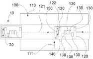
图6示意性地示出了根据本公开的示例的打印系统。打印系统100包括:打印介质前进系统(图6中未示出),其用于沿打印介质前进方向111传送打印介质110;可滑动打印头150,其具有多个喷嘴以将打印剂输送到打印介质110上;打印头支撑件120,其用于选择性地将可滑动打印头150支撑在包括第一打印头位置和第二打印头位置的多个打印头位置处,其中,第一打印头位置和第二打印头位置沿平行于打印介质前进方向111的方向间隔开。打印系统100还包括加盖站10,其具有盖20和定位机构40,盖20用于密封可滑动打印头150,定位机构40用于当可滑动打印头150处于第一打印头位置时将盖移动到第一盖位置并且当可滑动打印头140处于第二打印头位置时将盖移动到第二盖位置。另外,打印系统100包括传感器系统140,传感器系统140安装在打印头支撑件120处,以检测盖20的位置。FIG. 6 schematically illustrates a printing system according to an example of the present disclosure. The
图6的打印系统100可以类似于图1的打印系统。然而,图6的打印系统包括可滑动打印头。除了可滑动打印头150之外,该图的打印系统100包括固定地连接到打印头支撑件的多个打印头130。打印头支撑件120因此可以支撑可滑动打印头150和固定打印头130。在一些示例中,打印头支撑件可以支撑多个可滑动打印头150和/或多个固定打印头130。The
因此,可滑动打印头可以沿平行于打印介质前进方向111的方向在不同位置处将打印剂输送到打印介质上。例如,可滑动打印头可以根据打印情况而定位在其它打印头(可滑动的或固定的)下游或上游。上游打印头可以将打印剂输送在打印介质上,并且下游打印头可以将打印剂输送在先前沉积的打印剂之上。因此,打印介质上的图像可以包括由不同打印头输送的若干层打印剂。Thus, the slidable printhead can deliver print agent onto the print medium at different locations in a direction parallel to the print
沿平行于打印介质前进方向的方向移动打印头可以提供更紧凑和通用的设计。因此,可以减小打印头支撑件的空间和重量。这可能涉及打印头支撑件和移动打印头支撑件的驱动系统的成本降低。Moving the print head in a direction parallel to the direction in which the print media is advancing can provide a more compact and versatile design. Therefore, the space and weight of the print head support can be reduced. This may involve cost reductions for the printhead support and the drive system that moves the printhead support.
在该图中,打印头支撑件120包括开口122。可滑动打印头150可以沿平行于打印介质前进方向111的方向沿着开口122滑动。开口122可以包括多个接收器以在多个打印头位置处容纳可滑动打印头150。In this figure, the
在一些示例中,可滑动打印头可以包括固定系统以将可滑动打印头固定到打印头支撑件。在一些示例中,打印头支撑件可以包括支撑可滑动支撑件的可滑动打印头结构。可滑动打印头结构可以与可滑动打印头一起相对于打印头支撑件滑动。在一些示例中,用户可以从多个打印头位置选择打印头位置。例如,用户可以将可滑动打印头从第一打印头位置移动到第二打印头位置,并且可以将可滑动打印头锁定在第二打印头位置。In some examples, the slidable printhead may include a securing system to secure the slidable printhead to the printhead support. In some examples, the printhead support may include a slidable printhead structure supporting the slidable support. The slidable printhead structure can slide with the slidable printhead relative to the printhead support. In some examples, a user may select a printhead location from a plurality of printhead locations. For example, a user can move the slidable printhead from a first printhead position to a second printhead position and can lock the slidable printhead in the second printhead position.
在一些示例中,可滑动打印头结构可以类似于根据本文公开的任何示例的盖托架。In some examples, the slidable printhead structure may be similar to a cover carriage according to any of the examples disclosed herein.
在一些示例中,打印头支撑件可包括定位机构,以使可滑动打印头结构相对于打印头支撑件移位。打印头支撑件的定位机构可以类似于本文公开的加盖站的定位机构的任何示例。In some examples, the printhead support may include a positioning mechanism to displace the slidable printhead structure relative to the printhead support. The positioning mechanism of the printhead support may be similar to any of the examples of the positioning mechanism of the capping station disclosed herein.
该图的加盖站10可以是根据本文公开的任何示例。例如,加盖站可以包括可移动盖和固定盖。可移动盖可以安装在盖托架上,以在引导通道上移动,并且被定位机构固定在预定位置。可移动盖、盖托架、定位机构和引导通道可以根据本文公开的任何示例。The
加盖站可以包括多个识别特征,所述多个识别特征将由传感器识别以检测盖的位置。多个识别特征可以根据本文公开的任何示例。例如,多个识别特征可以包括与第一盖位置相关联的第一识别特征以及与第二盖位置相关联的第二识别特征。第一识别特征可以包括开口,并且第二识别特征可以包括一对开口。The capping station may include a plurality of identification features that will be recognized by sensors to detect the position of the cap. The plurality of identification features may be according to any of the examples disclosed herein. For example, the plurality of identification features may include a first identification feature associated with a first cover position and a second identification feature associated with a second cover position. The first identification feature may include an opening, and the second identification feature may include a pair of openings.
该图的传感器系统可以根据本文公开的安装在打印头支撑件上的传感器系统的任何示例。例如,传感器系统可以包括线传感器。线传感器可以读取在打印介质上创建的图像。线传感器可以用于校准打印系统。因此,单个传感器可以用于不同的方面。因此可以降低打印系统的成本。The sensor system of this figure may be in accordance with any example of a sensor system mounted on a printhead support disclosed herein. For example, the sensor system may include wire sensors. Line sensors can read images created on print media. Line sensors can be used to calibrate the printing system. Therefore, a single sensor can be used for different aspects. Therefore, the cost of the printing system can be reduced.
线传感器可以包括具有光源的发射器和接收器,发射器用于选择性地照射打印介质上的打印剂和多个识别特征,接收器用于接收反射回来的光。The line sensor may include an emitter with a light source for selectively illuminating the printing agent on the print medium and a plurality of identifying features, and a receiver for receiving the reflected light.
在一些示例中,打印系统可以包括控制器,以从传感器系统接收数据并且确定一个或多个盖的位置。控制器可以确定一个或多个可滑动打印头的位置。在一些示例中,控制器还可以控制打印系统的操作。控制器可以包括处理器和非暂时性机器可读存储介质。非暂时性机器可读存储介质可以联接到处理器。In some examples, the printing system may include a controller to receive data from the sensor system and determine the position of one or more covers. The controller may determine the position of one or more slidable printheads. In some examples, the controller may also control the operation of the printing system. The controller may include a processor and a non-transitory machine-readable storage medium. A non-transitory machine-readable storage medium may be coupled to the processor.
处理器对数据执行操作。在示例中,处理器是专用处理器,例如专用于控制加盖站的处理器。处理器还可以是中央处理单元。Processors perform operations on data. In an example, the processor is a dedicated processor, such as a processor dedicated to controlling the capping station. The processor may also be a central processing unit.
非暂时性机器可读存储介质可以包括存储可执行指令的任何电子、磁性、光学或其他物理存储设备。非暂时性机器可读存储介质可以是例如随机存取存储器(RAM)、电可擦除可编程只读存储器(EEPROM)、存储驱动器、光盘等。A non-transitory machine-readable storage medium may include any electronic, magnetic, optical, or other physical storage device that stores executable instructions. The non-transitory machine-readable storage medium may be, for example, random access memory (RAM), electrically erasable programmable read only memory (EEPROM), storage drives, optical disks, and the like.
在一些示例中,控制器可以用于执行根据本文公开的任何示例的用于为打印系统的打印头加盖的方法。In some examples, a controller may be used to perform a method for capping a printhead of a printing system according to any of the examples disclosed herein.
图7是根据本公开的示例的用于为打印系统的打印头加盖的方法的示例的框图。用于为打印系统的打印头加盖的方法300包括从打印头支撑件的多个预定打印头位置获取打印头位置,如在框310处表示的,以及基于所获取的打印头位置从加盖站的多个预定盖位置选择盖位置,如在框320处表示的。在方框330处表示了将可移动盖定位在所选择的盖位置处,并且在方框340处表示了使打印头支撑件和加盖站中的一个相对于彼此移动以将打印头定位在加盖站上方。方框350表示了检测可移动盖是否处于所选择的盖位置。在方框360处表示了当在所选择的盖位置处检测到可移动盖时提升可移动盖以密封打印头。7 is a block diagram of an example of a method for capping a printhead of a printing system according to an example of the present disclosure. The
可移动盖的位置可以被调节到打印头的位置以密封该打印头。因此,盖系统可以用于密封采用若干位置的打印头。在该方法中,打印系统可以根据本文公开的任何示例。The position of the removable cover can be adjusted to the position of the print head to seal the print head. Thus, the cap system can be used to seal the printhead in several positions. In this method, the printing system may be in accordance with any of the examples disclosed herein.
在一些示例中,打印头位置可以从传感器获取。在一个示例中,传感器可以是光学传感器。在一个示例中,传感器可以是与每个预定打印头位置相关联的机械传感器。由传感器接收的数据可以被控制器接收。In some examples, the printhead position may be obtained from a sensor. In one example, the sensor may be an optical sensor. In one example, the sensors may be mechanical sensors associated with each predetermined printhead position. The data received by the sensors can be received by the controller.
在一些示例中,用户接口装置可以接收指示打印头的位置的用户输入。用户接口装置可以连接到控制器以获取打印头位置。In some examples, the user interface device may receive user input indicating the location of the printhead. A user interface device may be connected to the controller to obtain the printhead position.
在一些示例中,打印头可以沿平行于打印介质前进方向的方向是可移动的。用户可以使打印头在打印头支撑件内的不同位置之间移位。In some examples, the printhead may be movable in a direction parallel to the direction of advance of the print medium. The user can shift the printhead between different positions within the printhead support.
根据所获取的打印头位置,可以从加盖站的预定盖位置选择盖位置。在一些示例中,控制器可以确定哪个盖位置对应于所获取的打印头位置。在一些示例中,用户可以选择盖位置。在一些示例中,打印头支撑件和加盖站可以包括指示标记以分别指示打印头支撑件和加盖站的位置。Based on the acquired printhead position, the capping position can be selected from predetermined capping positions of the capping station. In some examples, the controller may determine which cap position corresponds to the acquired printhead position. In some examples, the user may select the cover position. In some examples, the printhead support and the capping station may include indicator marks to indicate the location of the printhead support and the capping station, respectively.
在一些示例中,如在方框330处表示的,将可移动盖定位在所选择的盖位置处可包括使支撑可移动盖的盖托架在引导通道上滑动到所选择的盖位置。盖托架可根据本文所公开的任何示例在引导通道上滑动。在一些示例中,用户可以使盖托架移动跨过引导通道。在一些示例中,驱动机构可以使盖托架在引导通道内移位。In some examples, as represented at
在一些示例中,如在方框330处表示的,将可移动盖定位在所选择的盖位置处可包括将支撑可移动盖的盖托架锁定在所选择的盖位置处。盖托架可以被锁定到引导通道。In some examples, as represented at
锁定机构可用于将盖托架锁定到引导通道。锁定机构可以包括锁定元件,该锁定元件能够在锁定位置和滑动位置之间移动,在锁定位置,锁定元件接合引导通道以将盖托架锁定到引导通道,在滑动位置,锁定元件在引导通道上滑动。用户可以使锁定元件在锁定位置和滑动位置之间移动。例如,用户可以按压锁定元件以从锁定位置转换到滑动位置。用户可以释放施加在锁定元件上的压力,以将盖托架锁定到引导通道,例如将锁定元件插入引导通道的接收器中。A locking mechanism may be used to lock the cover bracket to the guide channel. The locking mechanism may include a locking element movable between a locking position in which the locking element engages the guide channel to lock the cover bracket to the guide channel and a sliding position where the locking element is on the guide channel slide. The user can move the locking element between the locked position and the sliding position. For example, the user may press the locking element to transition from the locked position to the sliding position. The user can release the pressure exerted on the locking element to lock the cover carrier to the guide channel, eg by inserting the locking element into the receptacle of the guide channel.
在一些示例中,移位构件可以使打印头支撑件和加盖站中的一个相对于打印头支撑件和加盖站中的另一个相对移动,以将打印头定位在加盖站(例如,可移动盖)上方。In some examples, the displacement member may relatively move one of the printhead support and the capping station relative to the other of the printhead support and the capping station to position the printhead at the capping station (eg, removable cover).
在一些示例中,使打印头支撑件和加盖站中的一个相对于彼此移动以将打印头定位在加盖站上方340包括使打印头支撑件沿扫描轴线朝向加盖站移动。打印头支撑件可以包括托架,该托架使打印头朝向加盖站移动跨过扫描轴线。扫描轴线打印系统的打印头支撑件因此可以使打印头朝向盖移动。In some examples, moving one of the printhead support and the capping station relative to each other to position the printhead over the
在一些示例中,移位构件可以使加盖站朝向打印头支撑件移动以使盖与打印头对准。在页宽阵列打印机系统中,加盖站可以朝向打印杆移动。例如,打印杆可以从打印区缩回,并且加盖站可以朝向处于缩回位置的打印杆旋转。In some examples, the displacement member may move the capping station toward the printhead support to align the cap with the printhead. In a page width array printer system, the capping station can be moved towards the print bar. For example, the print bar can be retracted from the print zone and the capping station can be rotated towards the print bar in the retracted position.
在一些示例中,检测可移动盖是否处于所选择的盖位置可以是在使打印头支撑件朝向加盖站移动期间。如参照图5所解释的,当打印头支撑件沿着扫描轴线移动以将打印头定位在加盖站上方,例如在可移动盖上方时,安装在打印头支撑件上的传感器可以识别与盖位置相关联的识别特征。In some examples, detecting whether the movable cover is in the selected cover position may be during moving the printhead support toward the capping station. As explained with reference to Figure 5, when the printhead support is moved along the scan axis to position the printhead over a capping station, such as over a movable cover, a sensor mounted on the printhead support can identify a connection with the cover Identifying features associated with a location.
在一些示例中,例如其中传感器在加盖站处,检测可移动盖是否处于所选择的盖位置可以在使打印头支撑件和加盖站中的一个相对于彼此移动之前执行。In some examples, such as where the sensor is at the capping station, detecting whether the movable cap is in the selected cap position may be performed before moving one of the printhead support and the capping station relative to each other.
在一些示例中,检测可移动盖是否处于所选择的盖位置350可包括从多个识别特征识别识别特征,其中,多个识别特征与多个预定盖位置相关联。在一些示例中,从多个识别特征识别识别特征可以包括用光源照射识别特征。在一些示例中,从多个识别特征识别识别特征可以包括将由识别特征反射回来的光的量与由具有多个识别特征的盖托架的一部分反射回来的光的量进行比较。In some examples, detecting whether the movable cover is in the selected
在检测到可移动盖处于所选择的盖位置之后,可移动盖可被提升以密封打印头。提升系统可朝向打印头提升可移动盖。After detecting that the movable cover is in the selected cover position, the movable cover can be lifted to seal the printhead. A lift system lifts the removable cover towards the print head.
在一些示例中,加盖站可以包括多个盖,例如具有可移动盖和固定盖。提升系统可以提升多个盖以密封对应的打印头。In some examples, the capping station may include multiple covers, eg, with a movable cover and a fixed cover. The lift system can lift multiple covers to seal the corresponding printheads.
已经呈现了前面的说明书以说明和描述某些示例。已经描述了不同组的示例;这些示例可以单独或组合应用,有时具有协同效应。本说明书不意图是穷举的,也不是要将这些原理限制为所公开的任何确切形式。根据上述教导,许多修改和变化是可能的。应当理解,关于任何一个示例描述的任何特征可以单独使用,或者与所描述的其他特征组合使用,并且还可以与任何其他示例或者任何示例的任何组合的任何特征组合使用。The foregoing specification has been presented to illustrate and describe certain examples. Different sets of examples have been described; these examples can be applied individually or in combination, sometimes with synergistic effects. This specification is not intended to be exhaustive, nor to limit these principles to any precise form disclosed. Many modifications and variations are possible in light of the above teachings. It should be understood that any feature described in relation to any one example may be used alone or in combination with other features described and also in combination with any feature of any other example or any combination of any examples.
Claims (15)
Translated fromChineseApplications Claiming Priority (1)
| Application Number | Priority Date | Filing Date | Title |
|---|---|---|---|
| PCT/US2020/033593WO2021236065A1 (en) | 2020-05-19 | 2020-05-19 | Capping stations with positioning mechanisms |
Publications (1)
| Publication Number | Publication Date |
|---|---|
| CN115066335Atrue CN115066335A (en) | 2022-09-16 |
Family
ID=78708755
Family Applications (1)
| Application Number | Title | Priority Date | Filing Date |
|---|---|---|---|
| CN202080096995.XAPendingCN115066335A (en) | 2020-05-19 | 2020-05-19 | Capping station with positioning mechanism |
Country Status (4)
| Country | Link |
|---|---|
| US (1) | US12179491B2 (en) |
| EP (1) | EP4076965A4 (en) |
| CN (1) | CN115066335A (en) |
| WO (1) | WO2021236065A1 (en) |
Citations (5)
| Publication number | Priority date | Publication date | Assignee | Title |
|---|---|---|---|---|
| US5325111A (en)* | 1992-12-28 | 1994-06-28 | Xerox Corporation | Removing waste ink from capping station |
| US5339102A (en)* | 1992-11-12 | 1994-08-16 | Xerox Corporation | Capping carriage for ink jet printer maintenance station |
| CN1155687A (en)* | 1995-11-24 | 1997-07-30 | 三星电子株式会社 | Apparatus and method for determining initial position and protecting capping release error in inkjet printer head |
| US6568787B1 (en)* | 1999-02-17 | 2003-05-27 | Hewlett-Packard Company | Apparatus and method for accurately positioning inkjet printheads |
| CN108481910A (en)* | 2017-02-13 | 2018-09-04 | 京瓷办公信息系统株式会社 | Ink-jet recording apparatus |
Family Cites Families (8)
| Publication number | Priority date | Publication date | Assignee | Title |
|---|---|---|---|---|
| JPH09164693A (en) | 1995-11-27 | 1997-06-24 | Xerox Corp | Liquid ink printer equipped with consumable goods for maintenance |
| US6520621B1 (en)* | 1999-01-08 | 2003-02-18 | Hewlett-Packard Company | Dual wiper scrapers for incompatible inkjet ink wipers |
| US6398339B1 (en)* | 2000-06-16 | 2002-06-04 | Xerox Corp. | Time and drive systems for a multifunction ink jet printer maintenance station |
| JP2005088217A (en) | 2003-09-12 | 2005-04-07 | Noritsu Koki Co Ltd | Printing device |
| JP2005199606A (en) | 2004-01-16 | 2005-07-28 | Fuji Photo Film Co Ltd | Image forming device and recording head control method |
| TWI266698B (en) | 2005-11-10 | 2006-11-21 | Benq Corp | Maintenance device used for cleaning a print head of an ink cartridge |
| KR100667847B1 (en) | 2005-12-23 | 2007-01-11 | 삼성전자주식회사 | Inkjet image forming apparatus |
| US8794738B2 (en) | 2009-12-22 | 2014-08-05 | Ricoh Company, Ltd. | Inkjet recording apparatus and method for maintenance of inkjet recording apparatus |
- 2020
- 2020-05-19CNCN202080096995.XApatent/CN115066335A/enactivePending
- 2020-05-19WOPCT/US2020/033593patent/WO2021236065A1/ennot_activeCeased
- 2020-05-19USUS17/999,256patent/US12179491B2/enactiveActive
- 2020-05-19EPEP20936208.6Apatent/EP4076965A4/enactivePending
Patent Citations (5)
| Publication number | Priority date | Publication date | Assignee | Title |
|---|---|---|---|---|
| US5339102A (en)* | 1992-11-12 | 1994-08-16 | Xerox Corporation | Capping carriage for ink jet printer maintenance station |
| US5325111A (en)* | 1992-12-28 | 1994-06-28 | Xerox Corporation | Removing waste ink from capping station |
| CN1155687A (en)* | 1995-11-24 | 1997-07-30 | 三星电子株式会社 | Apparatus and method for determining initial position and protecting capping release error in inkjet printer head |
| US6568787B1 (en)* | 1999-02-17 | 2003-05-27 | Hewlett-Packard Company | Apparatus and method for accurately positioning inkjet printheads |
| CN108481910A (en)* | 2017-02-13 | 2018-09-04 | 京瓷办公信息系统株式会社 | Ink-jet recording apparatus |
Also Published As
| Publication number | Publication date |
|---|---|
| EP4076965A1 (en) | 2022-10-26 |
| US12179491B2 (en) | 2024-12-31 |
| US20230211608A1 (en) | 2023-07-06 |
| EP4076965A4 (en) | 2023-09-27 |
| WO2021236065A1 (en) | 2021-11-25 |
Similar Documents
| Publication | Publication Date | Title |
|---|---|---|
| US8109585B2 (en) | Recording apparatus | |
| EP1707391B1 (en) | Image recording device | |
| US7533959B2 (en) | Medium position determining devices and image recording devices | |
| US6309044B1 (en) | Two stage print cartridge capping technique | |
| US20090309921A1 (en) | Recording apparatus | |
| US20090309922A1 (en) | Recording apparatus | |
| US6834925B2 (en) | Recording apparatus | |
| JP2007091445A (en) | Paper feeding device and image recording apparatus having the same | |
| US8770729B2 (en) | Image forming apparatus mounting replaceable liquid cartridge | |
| CN101444991A (en) | Image recording apparatus | |
| US5971641A (en) | Carriage driven tray lowering device for an ink jet printer | |
| JP4310652B2 (en) | Image recording device | |
| US20030007820A1 (en) | Franking machine | |
| KR0170036B1 (en) | Printing equipment | |
| US10946663B2 (en) | Inkjet printing apparatus | |
| US6406110B1 (en) | Mechanism to automate adjustment of printhead-to-print medium gap spacing on an imaging apparatus | |
| CN115066335A (en) | Capping station with positioning mechanism | |
| US8109603B2 (en) | Recording apparatus | |
| US5593152A (en) | Sheet media supply tray orients sheets to registration posts in imaging apparatus | |
| EP3877188A1 (en) | Printer carriage arrangements | |
| US8807694B2 (en) | Wicking accumulated ink away from optical sensor in inkjet printer | |
| US6378975B1 (en) | Drop detection using a movable strip | |
| EP2614959B1 (en) | Device for cleaning and closing print cartridges and closing element for closing print cartridges | |
| US8905508B2 (en) | Ink barrier for optical sensor in inkjet printer | |
| JPH09150522A (en) | Maintenance mechanism for print head |
Legal Events
| Date | Code | Title | Description |
|---|---|---|---|
| PB01 | Publication | ||
| PB01 | Publication | ||
| SE01 | Entry into force of request for substantive examination | ||
| SE01 | Entry into force of request for substantive examination | ||
| WD01 | Invention patent application deemed withdrawn after publication | Application publication date:20220916 | |
| WD01 | Invention patent application deemed withdrawn after publication |