CN115066267A - System and method for producing fluid for peritoneal dialysis - Google Patents
System and method for producing fluid for peritoneal dialysisDownload PDFInfo
- Publication number
- CN115066267A CN115066267ACN202180013491.1ACN202180013491ACN115066267ACN 115066267 ACN115066267 ACN 115066267ACN 202180013491 ACN202180013491 ACN 202180013491ACN 115066267 ACN115066267 ACN 115066267A
- Authority
- CN
- China
- Prior art keywords
- fluid
- concentrate
- water
- diluted
- unit
- Prior art date
- Legal status (The legal status is an assumption and is not a legal conclusion. Google has not performed a legal analysis and makes no representation as to the accuracy of the status listed.)
- Pending
Links
Images


Classifications
- A—HUMAN NECESSITIES
- A61—MEDICAL OR VETERINARY SCIENCE; HYGIENE
- A61M—DEVICES FOR INTRODUCING MEDIA INTO, OR ONTO, THE BODY; DEVICES FOR TRANSDUCING BODY MEDIA OR FOR TAKING MEDIA FROM THE BODY; DEVICES FOR PRODUCING OR ENDING SLEEP OR STUPOR
- A61M1/00—Suction or pumping devices for medical purposes; Devices for carrying-off, for treatment of, or for carrying-over, body-liquids; Drainage systems
- A61M1/14—Dialysis systems; Artificial kidneys; Blood oxygenators ; Reciprocating systems for treatment of body fluids, e.g. single needle systems for hemofiltration or pheresis
- A61M1/16—Dialysis systems; Artificial kidneys; Blood oxygenators ; Reciprocating systems for treatment of body fluids, e.g. single needle systems for hemofiltration or pheresis with membranes
- A61M1/1654—Dialysates therefor
- A61M1/1656—Apparatus for preparing dialysates
- A61M1/1672—Apparatus for preparing dialysates using membrane filters, e.g. for sterilising the dialysate
- A—HUMAN NECESSITIES
- A61—MEDICAL OR VETERINARY SCIENCE; HYGIENE
- A61M—DEVICES FOR INTRODUCING MEDIA INTO, OR ONTO, THE BODY; DEVICES FOR TRANSDUCING BODY MEDIA OR FOR TAKING MEDIA FROM THE BODY; DEVICES FOR PRODUCING OR ENDING SLEEP OR STUPOR
- A61M1/00—Suction or pumping devices for medical purposes; Devices for carrying-off, for treatment of, or for carrying-over, body-liquids; Drainage systems
- A61M1/14—Dialysis systems; Artificial kidneys; Blood oxygenators ; Reciprocating systems for treatment of body fluids, e.g. single needle systems for hemofiltration or pheresis
- A61M1/16—Dialysis systems; Artificial kidneys; Blood oxygenators ; Reciprocating systems for treatment of body fluids, e.g. single needle systems for hemofiltration or pheresis with membranes
- A61M1/1654—Dialysates therefor
- A—HUMAN NECESSITIES
- A61—MEDICAL OR VETERINARY SCIENCE; HYGIENE
- A61M—DEVICES FOR INTRODUCING MEDIA INTO, OR ONTO, THE BODY; DEVICES FOR TRANSDUCING BODY MEDIA OR FOR TAKING MEDIA FROM THE BODY; DEVICES FOR PRODUCING OR ENDING SLEEP OR STUPOR
- A61M1/00—Suction or pumping devices for medical purposes; Devices for carrying-off, for treatment of, or for carrying-over, body-liquids; Drainage systems
- A61M1/14—Dialysis systems; Artificial kidneys; Blood oxygenators ; Reciprocating systems for treatment of body fluids, e.g. single needle systems for hemofiltration or pheresis
- A61M1/28—Peritoneal dialysis ; Other peritoneal treatment, e.g. oxygenation
- A61M1/282—Operational modes
- A61M1/284—Continuous flow peritoneal dialysis [CFPD]
- A—HUMAN NECESSITIES
- A61—MEDICAL OR VETERINARY SCIENCE; HYGIENE
- A61M—DEVICES FOR INTRODUCING MEDIA INTO, OR ONTO, THE BODY; DEVICES FOR TRANSDUCING BODY MEDIA OR FOR TAKING MEDIA FROM THE BODY; DEVICES FOR PRODUCING OR ENDING SLEEP OR STUPOR
- A61M1/00—Suction or pumping devices for medical purposes; Devices for carrying-off, for treatment of, or for carrying-over, body-liquids; Drainage systems
- A61M1/14—Dialysis systems; Artificial kidneys; Blood oxygenators ; Reciprocating systems for treatment of body fluids, e.g. single needle systems for hemofiltration or pheresis
- A61M1/28—Peritoneal dialysis ; Other peritoneal treatment, e.g. oxygenation
- A61M1/287—Dialysates therefor
Landscapes
- Health & Medical Sciences (AREA)
- Heart & Thoracic Surgery (AREA)
- Urology & Nephrology (AREA)
- Emergency Medicine (AREA)
- Hematology (AREA)
- Engineering & Computer Science (AREA)
- Anesthesiology (AREA)
- Biomedical Technology (AREA)
- Vascular Medicine (AREA)
- Life Sciences & Earth Sciences (AREA)
- Animal Behavior & Ethology (AREA)
- General Health & Medical Sciences (AREA)
- Public Health (AREA)
- Veterinary Medicine (AREA)
- External Artificial Organs (AREA)
- Separation Using Semi-Permeable Membranes (AREA)
Abstract
Description
Translated fromChinese技术领域technical field
本发明涉及腹膜透析领域,并且涉及用于产生用于腹膜透析中的流体的系统和方法。The present invention relates to the field of peritoneal dialysis and to systems and methods for generating fluids for use in peritoneal dialysis.
背景技术Background technique
腹膜透析(PD)是用于治疗患有肾功能衰竭的患者的方法。在PD期间,患者的腹膜腔填充有新鲜的PD流体,并且废物和液体从患者的血液中经由腹膜被输送到PD流体。用过的PD流体随后从患者排出。Peritoneal dialysis (PD) is a method used to treat patients with kidney failure. During PD, the patient's peritoneal cavity is filled with fresh PD fluid, and waste products and fluids are transported from the patient's blood to the PD fluid via the peritoneum. The spent PD fluid is then drained from the patient.
存在若干种类的PD。在自动腹膜透析(APD)中,机器用于用新鲜的PD流体填充腹膜腔,并在特定的暂停时间后,机器将用过的PD溶液从体内排出。该程序重复数次,通常在夜晚进行。例如,在连续流动腹膜透析(CFPD)中,机器用于向患者的腹膜腔提供连续流动的新鲜PD流体,以及来自患者的连续流动的用过的PD流体。当今市场上的APD系统使用集中制造的PD流体,这些流体被运送给患者,准备好在储存在患者家中的袋中使用。There are several kinds of PDs. In automated peritoneal dialysis (APD), a machine is used to fill the peritoneal cavity with fresh PD fluid, and after a specific pause time, the machine drains the spent PD solution from the body. This procedure is repeated several times, usually at night. For example, in continuous flow peritoneal dialysis (CFPD), machines are used to provide a continuous flow of fresh PD fluid to the patient's peritoneal cavity, as well as a continuous flow of spent PD fluid from the patient. APD systems on the market today use centrally manufactured PD fluids that are delivered to the patient ready for use in bags stored in the patient's home.
PD流体的输送增加了处理成本并对环境具有负面影响。在患者家中储存PD流体对空间要求很高。治疗前患者对PD流体的处理增加了患者的负担,其中许多患者发现在治疗开始之前将PD流体袋放置在正确的位置是很难的。The delivery of PD fluids increases disposal costs and has a negative impact on the environment. Storing PD fluids in a patient's home is space-demanding. Pre-treatment patient handling of PD fluids increases the burden on patients, many of whom find it difficult to place the PD fluid bag in the correct position before treatment begins.
因此,需要减少上面列出的负面后果。Therefore, the negative consequences listed above need to be reduced.
发明内容SUMMARY OF THE INVENTION
本公开的目的是减轻现有技术的至少一些缺点。另一目的是提供一种用于在护理点处产生用于PD的流体的具有成本效益的解决方案。又一目的是提供一种用于在护理点处产生用于PD的流体的简洁的解决方案。再一个目的是提供一种消耗少量水的PD流体溶液。It is an object of the present disclosure to alleviate at least some of the disadvantages of the prior art. Another object is to provide a cost-effective solution for generating fluids for PD at the point of care. Yet another object is to provide a compact solution for generating fluids for PD at the point of care. Yet another object is to provide a PD fluid solution that consumes a small amount of water.
这些目的和其他目的至少部分地通过根据独立权利要求的系统和方法以及通过根据从属权利要求的实施例来实现。These and other objects are achieved at least in part by systems and methods according to the independent claims and by embodiments according to the dependent claims.
根据可以与本公开的任何其他方面或部分组合的一个方面,本公开涉及一种用于产生用于腹膜透析(PD)的流体的系统。该系统包括流体路径,该流体路径包括一个或多个PD浓缩液连接器和水连接器,每个PD浓缩液连接器被配置为连接到PD浓缩流体的一个或多个源,该水连接器被配置为连接到水源。该系统还包括正向渗透(FO)单元,该FO单元包括由FO膜分隔开的抽取侧和进给侧,该FO单元流体连接到流体路径。FO单元被配置为在抽取侧接收一种或多种PD浓缩流体并且在进给侧接收水以借助于抽取侧与进给侧之间的渗透压梯度通过FO膜将来自水的净化水输送送到一种或多种PD浓缩流体。因此一种或多种PD浓缩流体被稀释以产生经稀释的PD浓缩流体。提出的系统可以再稀释PD浓缩液的同时净化水,由此可以使水净化不那么复杂且成本更低。在实施例中,输送的净化水通过FO单元的FO膜被进一步净化。According to one aspect, which may be combined with any other aspect or portion of the present disclosure, the present disclosure relates to a system for generating fluid for peritoneal dialysis (PD). The system includes a fluid path including one or more PD concentrate connectors and a water connector, each PD concentrate connector configured to connect to one or more sources of PD concentrate fluid, the water connector be configured to connect to a water source. The system also includes a forward osmosis (FO) unit including an extraction side and a feed side separated by a FO membrane, the FO unit being fluidly connected to the fluid path. The FO unit is configured to receive one or more PD concentrate fluids on the draw side and water on the feed side to deliver purified water from the water through the FO membrane by means of an osmotic pressure gradient between the draw side and the feed side to one or more PD concentrate fluids. One or more PD-concentrated fluids are thus diluted to produce diluted PD-concentrated fluids. The proposed system can purify water while re-diluting the PD concentrate, thereby making water purification less complex and less expensive. In an embodiment, the delivered purified water is further purified by the FO membrane of the FO unit.
根据可以与本公开的任何其他方面或部分组合的另一方面,该系统包括浓度传感器和控制装置,该浓度传感器被配置为感测经稀释的PD浓缩流体的浓度,该控制装置被配置为基于感测到的浓度控制一种或多种PD浓缩液在经稀释的PD浓缩流体的产生期间的稀释程度,从而满足一个或多个预定标准。According to another aspect, which may be combined with any other aspect or portion of the present disclosure, the system includes a concentration sensor configured to sense a concentration of the diluted PD concentrate fluid and a control configured to be based on The sensed concentration controls the degree of dilution of the one or more PD concentrates during generation of the diluted PD concentrate fluid to satisfy one or more predetermined criteria.
根据可以与本公开的任何其他方面或部分组合的另一方面,一个或多个预定标准包括:经稀释的PD浓缩流体的浓度具有等于或接近于(例如,至少基本上等于)与最终的PD流体中经稀释的PD流体的规定浓度相匹配的浓度;经稀释的PD浓缩流体的浓度对应于PD流体的最终稀释程度;和/或经稀释的PD浓缩流体的浓度在一定时间内处于浓度区间内。According to another aspect that may be combined with any other aspect or portion of the present disclosure, the one or more predetermined criteria include that the diluted PD concentrate fluid has a concentration equal to or close to (eg, at least substantially equal to) the final PD A concentration that matches the stated concentration of the diluted PD fluid in the fluid; the concentration of the diluted PD concentrate fluid corresponds to the final degree of dilution of the PD fluid; and/or the concentration of the diluted PD concentrate fluid is within a concentration interval for a certain period of time Inside.
根据可以与本公开的任何其他方面或部分组合的另一方面,控制装置被配置为通过以下方式来控制一种或多种PD浓缩液的稀释程度:控制一种或多种PD浓缩流体到抽取侧的入口的流速,和/或控制水到进给侧的入口的流速,和/或控制来自进给侧的出口的废水的流速。According to another aspect, which may be combined with any other aspect or part of the present disclosure, the control device is configured to control the degree of dilution of the one or more PD concentrates by controlling the one or more PD concentrate fluids to draw The flow rate of the inlet to the side, and/or control the flow rate of the water to the inlet of the feed side, and/or control the flow rate of the waste water from the outlet of the feed side.
根据可以与本公开的任何其他方面或部分组合的另一方面,该系统包括流体连接或可连接到流体路径的容器,其中,该容器被布置成容纳经稀释的PD浓缩流体。According to another aspect, which may be combined with any other aspect or part of the present disclosure, the system includes a container fluidly connected or connectable to the fluid path, wherein the container is arranged to contain the diluted PD concentrate fluid.
根据可以与本公开的任何其他方面或部分组合的另一方面,流体路径包括第一再循环流体路径,该第一再循环流体路径包括容器和FO单元的抽取侧。控制装置被配置为通过在第一再循环流体路径中再循环经稀释的浓缩流体来控制稀释程度,直到满足一个或多个预定标准为止。According to another aspect, which may be combined with any other aspect or portion of the present disclosure, the fluid path includes a first recirculated fluid path including the vessel and the extraction side of the FO unit. The control device is configured to control the degree of dilution by recirculating the diluted concentrated fluid in the first recirculation fluid path until one or more predetermined criteria are met.
根据可以与本公开的任何其他方面或部分组合的另一方面,该系统包括泵,该泵被定位和布置成以下中的至少一个:(i)将经稀释的PD浓缩流体传送到沿着管线的容器或(ii)从沿着管线的容器移除经稀释的PD浓缩流体。According to another aspect, which may be combined with any other aspect or portion of the present disclosure, the system includes a pump positioned and arranged to at least one of: (i) deliver the diluted PD concentrate fluid to a line along the pipeline container or (ii) remove the diluted PD concentrate fluid from the container along the line.
根据可以与本公开的任何其他方面或部分组合的另一方面,该系统包括以下中的至少一个:(i)沿着管线定位的流体加热器,(ii)位于再循环流体路径中的浓缩液泵,其中,浓缩液泵可选地与阀流体平行地放置,或(iii)位于再循环流体路径中的空气/流体传感器,用于确定PD浓缩流体何时已到达传感器。According to another aspect, which may be combined with any other aspect or portion of the present disclosure, the system includes at least one of: (i) a fluid heater located along the pipeline, (ii) a concentrate located in the recirculation fluid path The pump, wherein the concentrate pump is optionally placed in parallel with the valve fluid, or (iii) an air/fluid sensor in the recirculation fluid path to determine when the PD concentrate fluid has reached the sensor.
根据可以与本公开的任何其他方面或部分组合的另一方面,流体路径包括第二再循环流体路径,该第二再循环流体路径包括FO单元的进给侧,其中,控制装置被配置为在第二再循环流体路径中再循环水,直到满足一个或多个预定标准为止。According to another aspect, which may be combined with any other aspect or part of the present disclosure, the fluid path comprises a second recirculated fluid path comprising the feed side of the FO unit, wherein the control device is configured to Water is recirculated in the second recirculation fluid path until one or more predetermined criteria are met.
根据可以与本公开的任何其他方面或部分组合的另一方面,控制装置被配置为在满足一个或多个预定标准时将经稀释的PD浓缩流体引导到出口连接器。According to another aspect, which may be combined with any other aspect or portion of the present disclosure, the control device is configured to direct the diluted PD concentrate fluid to the outlet connector when one or more predetermined criteria are met.
根据可以与本公开的任何其他方面或部分组合的另一方面,该系统包括水容器,该水容器被配置为收集FO单元下游的水。According to another aspect, which may be combined with any other aspect or portion of the present disclosure, the system includes a water container configured to collect water downstream of the FO unit.
根据可以与本公开的任何其他方面或部分组合的另一方面,流体路径包括渗透剂连接器,该渗透剂连接器被配置为连接到渗透剂源,并且其中控制装置被配置为将渗透剂从渗透剂源供应到流体路径,以在经稀释的PD浓缩流体中实现渗透剂的规定浓度。According to another aspect, which may be combined with any other aspect or part of the present disclosure, the fluid path includes a penetrant connector configured to connect to a source of osmotic agent, and wherein the control device is configured to transfer the osmotic agent from the osmotic agent A source of osmotic agent is supplied to the fluid path to achieve a specified concentration of osmotic agent in the diluted PD concentrate fluid.
根据可以与本公开的任何其他方面或部分组合的另一方面,流体路径包括入口连接器,该入口连接器被配置为连接到流出物源。FO单元被配置为在进给侧接收流出物,以借助于抽取侧与进给侧之间的渗透压梯度通过FO膜将来自流出物的水输送到一种或多种PD浓缩流体。因此,一种或多种PD浓缩流体被稀释以产生经预稀释的PD浓缩流体,其中,经预稀释的浓缩流体被包括在FO单元被配置为接收的一种或多种PD浓缩流体中。According to another aspect, which may be combined with any other aspect or portion of the present disclosure, the fluid path includes an inlet connector configured to connect to an effluent source. The FO unit is configured to receive the effluent on the feed side to deliver water from the effluent to one or more PD concentrate fluids through the FO membrane by means of an osmotic pressure gradient between the draw side and the feed side. Accordingly, the one or more PD concentrate fluids are diluted to produce a pre-diluted PD concentrate fluid, wherein the pre-diluted PD concentrate fluid is included in the one or more PD concentrate fluids that the FO unit is configured to receive.
根据可以与本公开的任何其他方面或部分组合的另一方面,该系统包括流体连接到或可连接到流体路径的流出物容器,其中,该容器被布置成容纳来自患者的流出物。According to another aspect, which may be combined with any other aspect or part of the present disclosure, the system includes an effluent container fluidly connected or connectable to the fluid path, wherein the container is arranged to contain effluent from a patient.
根据可以与本公开的任何其他方面或部分组合的另一方面,该系统包括预处理单元,该预处理单元被配置为在经由水连接器接收到的水被传递到FO单元之前对经由水连接器接收到的水进行预处理。According to another aspect, which may be combined with any other aspect or part of the present disclosure, the system includes a pretreatment unit configured to connect the water via the water connection before the water received via the water connector is passed to the FO unit. The water received by the device is pretreated.
根据可以与本公开的任何其他方面或部分组合的另一方面,本公开包括一种用于在包括正向渗透(FO)单元的系统中产生用于腹膜透析(PD)的流体的方法。该FO单元包括由FO膜分隔开的抽取侧和进给侧。该FO单元被配置为在抽取侧接收一种或多种PD浓缩流体并且在进给侧接收水,以借助于抽取侧与进给侧之间的渗透压梯度通过FO膜将来自水的净化水输送到一种或多种PD浓缩流体,从而将一种或多种PD浓缩流体稀释成经稀释的PD浓缩流体。该方法包括将水引导到FO单元的进给侧,并将一种或多种PD浓缩流体引导到抽取侧。According to another aspect, which may be combined with any other aspect or portion of the present disclosure, the present disclosure includes a method for producing fluid for peritoneal dialysis (PD) in a system including a forward osmosis (FO) unit. The FO unit includes an extraction side and a feed side separated by a FO membrane. The FO unit is configured to receive one or more PD concentrate fluids on the draw side and water on the feed side to pass purified water from the water through the FO membrane by means of an osmotic pressure gradient between the draw side and the feed side The one or more PD-concentrated fluids are delivered to dilute the one or more PD-concentrated fluids into a diluted PD-concentrated fluid. The method includes directing water to the feed side of the FO unit and directing one or more PD concentrate fluids to the draw side.
根据可以与本公开的任何其他方面或部分组合的另一方面,该方法包括:感测经稀释的PD浓缩流体的浓度,以及基于感测到的浓度控制一种或多种PD浓缩液在经稀释的PD浓缩流体的产生期间的稀释程度,从而满足一个或多个预定标准。According to another aspect, which may be combined with any other aspect or portion of the present disclosure, the method includes sensing a concentration of the diluted PD concentrate fluid, and controlling the concentration of the one or more PD concentrates in the diluted PD concentrate based on the sensed concentration. The degree of dilution during generation of the diluted PD concentrate fluid to meet one or more predetermined criteria.
根据可以与本公开的任何其他方面或部分组合的另一方面,一个或多个预定标准包括:经稀释的PD浓缩流体的浓度具有等于或接近于(例如,至少基本上等于)与最终的PD流体中经稀释的PD流体的规定浓度相匹配的浓度;经稀释的PD浓缩流体的浓度对应于PD流体的最终稀释程度;和/或经稀释的PD浓缩流体的浓度在一定时间内处于浓缩区间内。According to another aspect that may be combined with any other aspect or portion of the present disclosure, the one or more predetermined criteria include that the diluted PD concentrate fluid has a concentration equal to or close to (eg, at least substantially equal to) the final PD A concentration that matches the stated concentration of the diluted PD fluid in the fluid; the concentration of the diluted PD concentrate fluid corresponds to the final degree of dilution of the PD fluid; and/or the concentration of the diluted PD concentrate fluid is in the concentration range for a certain period of time Inside.
根据可以与本公开的任何其他方面或部分组合的另一方面,该方法包括:通过以下方式来控制一种或多种PD浓缩液的稀释程度:控制一种或多种PD浓缩流体到抽取侧的入口的流速,和/或控制水在进给侧的入口处的流速,和/或控制来自进给侧的出口的废水的流速。According to another aspect, which may be combined with any other aspect or portion of the present disclosure, the method includes controlling the degree of dilution of the one or more PD concentrates by controlling the one or more PD concentrate fluids to the draw side The flow rate of the inlet, and/or control the flow rate of the water at the inlet of the feed side, and/or control the flow rate of the waste water from the outlet of the feed side.
根据可以与本公开的任何其他方面或部分组合的另一方面,该方法包括:将经稀释的PD浓缩流体引导到容器中。According to another aspect, which may be combined with any other aspect or portion of the present disclosure, the method includes directing the diluted PD concentrate fluid into a container.
根据可以与本公开的任何其他方面或部分组合的另一方面,该方法包括:通过在第一再循环流体路径中再循环经稀释的浓缩流体来控制稀释程度,直到满足一个或多个预定标准为止,该第一再循环流体路径包括容器和FO单元的抽取侧。According to another aspect, which may be combined with any other aspect or portion of the present disclosure, the method includes controlling the degree of dilution by recirculating the diluted concentrated fluid in the first recirculation fluid path until one or more predetermined criteria are met So far, the first recirculation fluid path includes the vessel and the extraction side of the FO unit.
根据可以与本公开的任何其他方面或部分组合的另一方面,该方法包括:通过在第二再循环流体路径中再循环水来控制稀释程度,直到满足一个或多个预定标准为止,该第二再循环流体路径包括FO单元的进给侧。According to another aspect, which may be combined with any other aspect or portion of the present disclosure, the method includes controlling the degree of dilution by recirculating water in the second recirculation fluid path until one or more predetermined criteria are met, the first Two recirculating fluid paths include the feed side of the FO unit.
根据可以与本公开的任何其他方面或部分组合的另一方面,该方法包括:将FO单元下游的用过的水引导到水容器。According to another aspect, which may be combined with any other aspect or portion of the present disclosure, the method includes directing spent water downstream of the FO unit to a water container.
根据可以与本公开的任何其他方面或部分组合的另一方面,该方法包括将渗透剂从渗透剂源供应到流体路径,以在经稀释的PD浓缩流体中实现渗透剂的规定浓度。According to another aspect, which may be combined with any other aspect or portion of the present disclosure, the method includes supplying an osmotic agent from a source of osmotic agent to the fluid path to achieve a specified concentration of osmotic agent in the diluted PD concentrate fluid.
根据可以与本公开的任何其他方面或部分组合的另一方面,该方法包括:将来自流出物源的流出物引导到FO单元的进给侧,以借助于抽取侧与进给侧之间的渗透压梯度通过FO膜将来自流出物的水输送到一种或多种PD浓缩流体。因此,一种或多种PD浓缩流体被稀释以产生经预稀释的PD浓缩流体,其中,经预稀释的浓缩液被包括在FO单元被配置为接收的一种或多种PD浓缩流体中。According to another aspect, which may be combined with any other aspect or portion of the present disclosure, the method includes directing effluent from the effluent source to the feed side of the FO unit for by means of a connection between the extraction side and the feed side. An osmotic pressure gradient transports water from the effluent to one or more PD concentrate fluids through the FO membrane. Accordingly, the one or more PD concentrate fluids are diluted to produce a pre-diluted PD concentrate fluid, wherein the pre-diluted concentrate fluid is included in the one or more PD concentrate fluids that the FO unit is configured to receive.
根据可以与本公开的任何其他方面或部分组合的另一方面,该方法包括:在经由水连接器接收到的水被传递到FO单元之前对经由水连接器接收到的水进行预处理。According to another aspect, which may be combined with any other aspect or part of the present disclosure, the method includes pre-treating the water received via the water connector before the water received via the water connector is passed to the FO unit.
根据可以与本公开的任何其他方面或部分组合的另一方面,该方法包括:在满足一个或多个预定标准时将经稀释的PD浓缩流体引导到出口容器。According to another aspect, which may be combined with any other aspect or portion of the present disclosure, the method includes directing the diluted PD concentrate fluid to an outlet container when one or more predetermined criteria are met.
根据可与本公开的任何其他方面或部分组合的另一方面,一种或多种PD浓缩液源中的一个包括流体,该流体包括乳酸盐、乙酸盐、柠檬酸盐、碳酸氢盐、NaCl、MgCl2、CaCl2和KCl中的一个或多个。According to another aspect that may be combined with any other aspect or portion of the present disclosure, one of the one or more PD concentrate sources includes a fluid including lactate, acetate, citrate, bicarbonate One or more of , NaCl, MgCl2, CaCl2, and KCl.
根据可以与本公开的任何其他方面或部分组合的又一方面,本公开涉及一种计算机程序,该计算机程序包括使根据任意系统方面的系统执行根据任意方法方面的方法的步骤的指令。According to yet another aspect, which may be combined with any other aspect or part of the present disclosure, the present disclosure relates to a computer program comprising instructions for causing a system according to any of the system aspects to perform the steps of the method according to any of the method aspects.
根据可以与本公开的任何其他方面或部分组合的又一方面,本公开涉及一种其上存储有计算机方面的计算机程序的计算机可读存储器。According to yet another aspect, which may be combined with any other aspect or part of the present disclosure, the present disclosure relates to a computer-readable memory having stored thereon a computer program of a computer aspect.
附加的特征和优点在下面的具体实施方式部分和附图中进行了描述,并且将从下面的具体实施方式部分和附图中显而易见。本文所描述的特征和优点不是无所不包的,特别地,鉴于附图和描述,许多附加特征和优点对于本领域普通技术人员而言将是显而易见的。此外,任何特定实施例不必具有本文列出的所有优点,并且明确地预期分别要求单独的有利实施例。此外,应该注意,在说明书中使用的语言主要是为了可读性和指导目的而选择的,因此不限制本发明主题的范围。Additional features and advantages are described in, and will be apparent from, the Detailed Description and the Drawings below. The features and advantages described herein are not all-inclusive and, in particular, many additional features and advantages will be apparent to those of ordinary skill in the art in view of the drawings and description. Furthermore, it is not necessary for any particular embodiment to have all of the advantages listed herein, and it is expressly contemplated that a separate advantageous embodiment will be required for each. Furthermore, it should be noted that the language used in the specification has been principally selected for readability and instructional purposes, and therefore does not limit the scope of the inventive subject matter.
附图说明Description of drawings
图1和图4至图9示出了根据一些实施例的用于产生用于PD的流体的系统。1 and 4-9 illustrate a system for generating fluid for PD, according to some embodiments.
图2和图3是示出根据一些实施例的用于产生用于PD的流体的方法的流程图。2 and 3 are flowcharts illustrating methods for generating fluid for PD, according to some embodiments.
具体实施方式Detailed ways
在以下公开内容中,描述用于产生用于PD的流体的系统和方法的若干实施例。实施例各自利用正向渗透(FO)单元来使用来自水的通过FO膜输送的净化水来稀释一种或多种PD浓缩液。水在通过FO膜被输送时变为净化的,并将在FO膜的另一侧上的PD浓缩液直接稀释成经稀释的PD浓缩流体。经稀释的PD浓缩液可以被再循环,直到它通过FO膜拉取足够的水以达到期望的稀释度。经稀释的PD浓缩液可能在FO期之后具有最终的PD流体的规定组成,或者可能需要在其具有PD流体的规定组成之前与附加的PD浓缩液(例如,包括渗透剂的PD流体)混合。PD流体可以被限定为准备好由患者在PD处理中使用的PD流体。该系统可用于自动化PD的不同变体,包括PD流体的在线混合和PD流体的分批混合。水在用于FO单元6之前可以被预处理。In the following disclosure, several embodiments of systems and methods for generating fluids for PD are described. The examples each utilize a forward osmosis (FO) unit to dilute one or more PD concentrates using purified water from water delivered through a FO membrane. The water becomes purified as it is transported through the FO membrane and directly dilutes the PD concentrate on the other side of the FO membrane into a diluted PD concentrate fluid. The diluted PD concentrate can be recycled until it pulls enough water through the FO membrane to achieve the desired dilution. The diluted PD concentrate may have the specified composition of the final PD fluid after the FO period, or may need to be mixed with additional PD concentrate (eg, PD fluid including an osmotic agent) before it has the specified composition of the PD fluid. PD fluid may be defined as PD fluid that is ready for use by a patient in PD treatment. The system can be used to automate different variants of PD, including in-line mixing of PD fluids and batch mixing of PD fluids. The water can be pretreated before being used in the
FO单元中使用的水可以是原水(例如,自来水)或经预处理的原水。本文描述的系统可以包括预处理模块,该预处理模块被布置为在将原水提供给FO单元之前对其进行处理。The water used in the FO unit can be raw water (eg, tap water) or pretreated raw water. The system described herein may comprise a pretreatment module arranged to treat the raw water before it is provided to the FO unit.
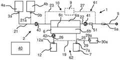
在下文中,参考图1描述用于产生用于PD的流体的系统。全部附图中相同的参考标记通常将不再重复。系统1包括流体路径2、多个连接器和正向渗透(FO)单元6。流体路径2可以被封闭在外壳(图1中未示出)内。流体路径2可以是装置的一部分。流体路径2包括多个流体管线。这些流体管线可以是如本文描述的多个或全部流体管线。连接器包括一个或多个PD浓缩液连接器3a、3b。每个PD浓缩液连接器3a、3b被配置为连接到PD浓缩流体的源头4a、4b。PD浓缩流体的源通常是装有PD浓缩液的袋。然后每个PD浓缩液连接器3a、3b被配置为连接到设置有PD浓缩流体的袋的对应的连接器。连接器还包括水连接器7a。水连接器7a可以是水端口。水连接器7a通常被配置为连接到原水源,例如连接到水龙头的软管。因此,原水可以是自来水。在将水供应到FO单元6之前,可以对水进行预处理。In the following, a system for generating fluid for PD is described with reference to FIG. 1 . The same reference numerals will generally not be repeated throughout the drawings. The
系统1还可以包括预处理单元8(图4至图8),该预处理单元被配置为在经由水连接器7a接收到的水被传递到FO单元6之前对其进行预处理。FO单元6包括通过FO膜6c分隔开的抽取侧6a和进给侧6b。FO膜6c通常具有纳米(nm)范围内的孔径,例如从0.5至5nm或更小,这取决于打算被阻挡的溶质。FO单元6流体连接到流体路径2。FO单元6被配置为在抽取侧6a接收一种或多种PD浓缩流体4a、4b并且在进给侧6b接收(经预处理的)水,以借助于抽取侧6a与进给侧6b之间的渗透压梯度通过FO膜6c将来自水的净化水输送到一种或多种PD浓缩流体。因此,一种或多种PD浓缩流体被稀释成经稀释的PD浓缩流体。适用于FO单元6的FO单元可由AquaporinTM、AsahiKASEITM、BerghofTM、CSMTM、FTSH2OTM、KochMembraneSystemsTM、PoriferaTM、ToyoboTM和TorayTM提供。The
FO膜6c可以是透水膜,该透水膜将水(进给侧)和PD浓缩液(抽取侧)分离开。不同侧6a、6b中的流体可以逆流或并流流动。水可以单程流动,因此,用过的水可以在已经通过进给侧6b一次之后被传递到排放口。同样,FO膜6c可以具有在纳米(nm)范围内的孔径,例如,从0.5至5nm或更小,这取决于打算被阻挡的溶质。FO膜6c通常被设计成或多或少地对水分子具有排他地选择性,这使得该膜能够将水与所有其他污染物分离开,从而被进一步净化。膜的几何形状可以是平板纤维、管状纤维或中空纤维。或者,水可以被再循环一次或多次到进给侧6b和/或抽取侧流体可以被再循环一次或多次到抽取侧6a。来自水的净化水借助于由水(进给溶液)与一种或多种PD浓缩流体(抽取溶液)之间的渗透压差产生的驱动力通过FO膜6c输送。这意味着水将在整个FO过程中变得更加浓缩。另一方面,一种或多种PD浓缩液将在整个FO过程中将越来越稀释。FO膜6c可以是能够促进正向渗透过程的水处理膜。它是允许水从低浓缩液侧(进给侧)流向高浓缩液侧(抽取侧)的半透膜。FO膜通常包括薄的排斥层(rejection layer)(或活性层)和下面的多孔载体。膜的几何形状可以是平板纤维、管状纤维或中空纤维。The FO membrane 6c may be a water permeable membrane that separates water (feed side) and PD concentrate (extract side). The fluids in the
更详细地说,第一PD浓缩液袋4a经由第一袋连接器(未示出)连接到第一PD浓缩液连接器3a。第一流体管线21流体连接在抽取侧6a的入口端口与第一PD浓缩液连接器3a之间。因此,第一流体管线21连接第一PD浓缩液连接器3a和抽取侧6a。第二PD浓缩液袋4b经由第二袋连接器(未示出)连接到第二PD浓缩液连接器3b。流体管线21a流体连接在第二PD浓缩液连接器3b与第一流体管线21之间。因此,流体管线21a连接第二PD浓缩液连接器3b和第一流体管线21。因此,流体路径2包括第二PD浓缩液连接器3b。第二PD浓缩液连接器3b被配置为连接到包含渗透剂的流体源。替代地,流体管线21a可以连接到第二流体管线22,以将PD浓缩液从第二PD流体袋4b供应到经稀释的PD流体。In more detail, the first
第二流体管线22流体连接在抽取侧6a的出口与出口连接器5a之间。例如,出口连接器5a是出口端口。因此,第二流体管线22流体连接抽取侧6a和出口连接器5a。出口连接器5a被配置为连接到流体管线5的对应连接器(未示出),该流体管线5被配置为将最终的PD流体直接输送到患者的导管、到用于将流体泵送至患者的循环仪或到批次容器。第一泵41被配置为控制经稀释的PD浓缩流体在第二流体管线22中的流速。同时,第一泵41可以控制(如果没有设置泵43)PD浓缩流体在第一流体管线21中的流速。在一些实施例中,第三泵43被布置成控制一种或多种PD浓缩流体在第一流体管线21中的流速,并因此控制到抽取侧6a或到容器9的流速,如果存在的话。下面进一步解释容器9。第三流体管线25连接在水连接器7a与进给侧6b的入口端口之间。因此,第三流体管线25流体连接水连接器7a和供给侧6b。第四流体管线26连接在进给侧6b的出口端口和排放连接器12a之间。因此,第四流体管线26连接供给侧6b和排放连接器12a。第二泵42被布置成控制来自进给侧6b的废水的流速。在示出的实施例中,第二泵42被布置成与第四流体管线26一起操作。排放连接器12a被配置为连接到排放管线(未示出)的对应连接器,该排放管线可以连接到排放口以去除使用后的废水或连接到用过的水的袋或水容器。因此,在一些实施例中,系统1包括水容器12,该水容器12被配置为收集FO单元6下游的用过的水。用过的水可以在即将到来的FO期中(例如,在FO期的第一部分期间)用作进给溶液,从而减少用水量。The
浓度传感器51被布置成感测第二流体管线22中的流体的浓度。因此,浓度传感器51被定位成感测经稀释的PD浓缩流体的浓度。在一些实施例中,系统1包括容器9。容器9流体连接或可连接到流体路径2。容器9被布置成容纳经稀释的PD浓缩流体。容器9也可用于在将一种或多种浓缩液供应到抽取侧6a之前收集该一种或多种浓缩液。变型实施例是将一种或多种浓缩液预填充在容器9中以用于混合以形成批次,该批次可以是用于整个处理的批次。然后可以在稀释过程之后添加附加的浓缩液。在包括容器9的实施例中,第五流体管线27流体连接在浓度传感器41下游的第二流体管线22与容器9之间。因此,第五流体管线27流体连接第二流体22和容器9。第六流体管线23连接在容器9与第一流体管线21之间。因此,第六流体管线23流体连接容器9和第一流体管线21。在示出的实施例中,抽取侧6a、第二流体管线22的一部分、第五流体管线27、容器9、第六流体管线23和第一流体管线21的一部分形成第一再循环流体路径61。因此,流体路径2包括第一再循环流体路径61,该第一再循环流体路径61包括FO单元6的抽取侧6a和容器9。控制装置10被配置为通过在第一再循环流体路径61中再循环经稀释的浓缩流体来控制稀释程度,直到满足一个或多个预定标准为止。The
浓度传感器51例如是被配置为感测流体的电导率的电导率传感器,或被配置为感测流体的电阻率的电阻率传感器。如果需要且如本领域已知的,即使使用例如电阻率传感器,感测到的值也可以被转换成电导率值。电导率同样可以被转换成电阻率。The
在一些实施例中,系统1包括布置在第三流体管线25与第四流体管线26之间的第七流体管线19。因此,第七流体管线19连接第三流体管线25和第四流体管线26。第二再循环流体路径62中包括进给侧6b、第三流体管线25的一部分、第七流体管线19和第四流体管线26的一部分。因此,在示出的实施例中,流体路径2形成包括FO单元6a的进给侧6b的第二再循环流体路径62。控制装置10被配置为在第二再循环流体路径62中再循环水,直到满足一个或多个预定标准为止。待循环的水可以被收集在附加的容器(未示出)中,进出附加的容器和第二再循环路径62的水可以经由附加的容器中的一个或两个端口被传递。附加的阀(未示出)可以被布置成控制水流入和流出附加的容器。In some embodiments, the
在一些实施例中,流出物(即,来自患者的用过的PD流体)在水被用作进给溶液之前被用作进给溶液。然后FO单元6被配置为在进给侧6b接收流出物。借助于抽取侧6a与进给侧6b之间的渗透压梯度通过FO膜6将水从流出物输送到一种或多种PD浓缩流体,从而稀释一种或多种PD浓缩流体以产生经预稀释的PD浓缩流体。经预稀释的PD浓缩流体被收集在容器9中。然后,经预稀释的浓缩流体是FO单元6被配置为接收的一种或多种PD浓缩流体中的一种。因此,一种或多种PD浓缩液可以在用来自原水或经预处理的水的净化水进一步稀释之前,用经由FO从流出物中汲取的水进行预稀释。因此,节省了附加的水。在这种实施例中,流体路径2可以包括入口连接器29a。第八流体管线29连接在入口连接器29a与第三流体管线25之间。第八流体管线29流体连接入口连接器29a和第三流体管线25。入口连接器29a连接到附接到流出物的源30a的对应连接器(未示出)。流出物的源30a可以是具有来自流出物从PD患者的先前排放的流出物的流出物容器或袋。因此,在一些实施例中,流体路径2包括入口连接器29a,该入口连接器29a被配置为连接到流出物的源30a(例如,流出物容器)。在一些实施例中,该系统包括流体连接或可连接到流体路径2的流出物容器。流出物容器被布置成容纳来自患者的流出物。In some embodiments, the effluent (ie, spent PD fluid from the patient) is used as the feed solution before water is used as the feed solution. The
系统1还包括控制装置10。控制装置10包括控制单元40,该控制单元40包括处理器和存储器。存储器通常存储程序,该程序在由处理器执行时控制系统1。控制单元40还可以包括通信接口,该通信接口使控制单元40能够将数据和信号传达到系统1的组件并且可以传达来自系统1的组件的数据和信号,例如,向阀和泵发送控制信号,以及接收来自浓度传感器的感测到的数据和来自阀和泵的反馈信号。控制装置10还可以包括示出的泵41、42、43中的任何一个或多个。控制装置10还可以包括阀,为了便于图示,该阀未被包括在图1中。如本文所描述的阀通常是开/关阀并且可以是二通阀或三通阀。The
在一些实施例中,控制装置10被配置为基于经稀释的PD流体的感测到的浓度在经稀释的PD浓缩流体的产生期间控制一种或多种PD浓缩液的稀释程度,使得满足一个或多个预定标准。根据PD流体的产生中的当前阶段,可以使用不同的标准,下文将对此进行更详细的解释。在一些实施例中,控制装置10被配置为通过以下方式来控制一种或多种PD浓缩液的稀释程度:控制一种或多种PD浓缩流体到抽取侧6a的入口的流速,和/或控制水到进给侧6b的入口的流速,和/或控制来自进给侧6b的出口的废水的流速。一种或多种PD浓缩流体到抽取侧6a的入口的流速可以用第一泵41控制。水到进给侧6b的入口的流速可以用第二泵42控制。例如,泵41至43中的任何一个或多个以及本文描述的任何其他泵是容积泵,例如活塞泵或隔膜泵。替代地,泵41至43中的任何一个或多个以及本文描述的任何其他泵可以是与流量计或称重秤一起使用的流量泵。In some embodiments, the
在一些实施例中,仅一种第一种类的PD浓缩液用作抽取溶液。那么PD浓缩液包括例如缓冲剂。然后另一种第二种类的PD浓缩液可以在FO期之后被供应到经稀释的PD浓缩液。该另一种第二种类的PD浓缩液包括例如渗透剂。该另一种第二种类的PD浓缩液例如是葡萄糖。替代地,该另一种第二种类的PD浓缩液与第一种类的PD浓缩液一起用作抽取溶液。因此,控制装置10被配置为将渗透剂从渗透剂源4b供应到流体路径2,以在经稀释的PD浓缩流体中实现渗透剂的规定浓度。In some embodiments, only one PD concentrate of the first species is used as the extraction solution. The PD concentrate then includes, for example, a buffer. Another second type of PD concentrate can then be supplied to the diluted PD concentrate after the FO period. This other second type of PD concentrate includes, for example, an osmotic agent. The other second type of PD concentrate is, for example, dextrose. Alternatively, the other PD concentrate of the second kind is used as an extraction solution together with the PD concentrate of the first kind. Accordingly, the
经稀释的PD浓缩液可以在第一再循环流体路径61中被再循环,直到感测到的浓度满足最终的PD流体的一个或多个标准为止。通常,感测到的浓度应该在某个区间内。当这实现时,控制装置10被配置为将经稀释的PD浓缩流体引导到出口连接器5a。另一个标准是例如PD流体是现成的并且有一定的时间到期。The diluted PD concentrate may be recirculated in the first
最终的PD流体具有实现了规定或预定的组成的PD浓缩液和水的组成。因此,也已知最终的PD流体应具有的一种或多种PD浓缩液的规定浓度,例如,1.36%、2.27%或3.86%的葡萄糖。最终的PD流体是准备好传送到患者的腹膜腔的PD流体。产生速率可以是分批的,即应该产生特定体积的最终的PD流体。然后特定体积为批次。或者,最终的PD流体的产生是连续的,其被传送直到控制装置10确定传送应该停止为止。The final PD fluid has a composition of PD concentrate and water that achieves a specified or predetermined composition. Therefore, it is also known that the final PD fluid should have a specified concentration of one or more PD concentrates, eg, 1.36%, 2.27%, or 3.86% glucose. The final PD fluid is the PD fluid ready for delivery to the patient's peritoneal cavity. The production rate can be batchwise, ie a specific volume of final PD fluid should be produced. Then a specific volume is a batch. Alternatively, final PD fluid production is continuous, which is delivered until the
一种或多种PD浓缩液源4a中的一个可以包括流体,该流体包括以下中的一个或多个:乳酸盐、乙酸盐、柠檬酸盐、碳酸氢盐、KCl、MgCl2、CaCl2和NaCl。例如,PD浓缩液源包括含有缓冲剂的流体,例如以下中的一个或多个:乳酸盐、柠檬酸盐、乙酸盐和碳酸氢盐。该流体在用水和可能的其他PD浓缩液稀释时成为最终的PD流体,该最终的PD流体具有适用于PD处理的pH值,并且为以下中的一个或多个:KCL、MgCl2、CaCl2、NaCl。One of the one or more PD concentrate
图2是根据一些实施例的用于借助于流出物和一种或多种PD浓缩液产生经预稀释的PD流体的方法的流程图。图3是根据本文描述的一些实施例的用于产生用于PD的流体的方法的流程图。这些方法可以作为计算机程序上的指令实现并保存在控制单元40的存储器中。这些方法与图2和图3的流程图一起解释。以虚线示出的框对应于替代或可选功能或程序。2 is a flow diagram of a method for generating pre-diluted PD fluids with effluent and one or more PD concentrates, according to some embodiments. 3 is a flowchart of a method for generating fluid for PD, according to some embodiments described herein. These methods may be implemented as instructions on a computer program and stored in the memory of the
参考图2,在S1a处,方法包括将来自流出物的源30a的流出物引导到FO单元6a的进给侧6b。在S1b处,方法还包括将一种或多种PD浓缩流体引导到抽取侧6a中。然后借助于抽取侧6a与进给侧6b之间的渗透压梯度通过FO膜6将来自流出物的水输送到一种或多种PD浓缩流体,从而稀释一种或多种PD浓缩流体并产生经预稀释的PD浓缩流体。此后,经预稀释的浓缩流体被包括在FO单元6被配置为接收的一种或多种PD浓缩流体中。在一个实施例中,用作抽取溶液的一种或多种PD浓缩液包括包含一种或多种缓冲剂的PD浓缩流体。Referring to Figure 2, at S1a, the method includes directing effluent from a
在S1c处,方法还包括例如利用浓度传感器51感测经稀释的PD浓缩流体的浓度。该方法还包括在S1d处,将经稀释的PD浓缩流体引导到容器9中。因此,可以使用来自患者的先前排放的流出物预稀释PD浓缩液。At S1c, the method further includes sensing the concentration of the diluted PD-concentrated fluid, eg, with
参考图3中的流程图解释用于产生用于PD的流体的方法。如图2的流程图中描述的方法可以在图3中描述的方法之前执行。可以使用本文描述的系统1中的任何一个来执行该方法。在该方法开始之前,系统1连接到水源7,例如,经由软管连接到水龙头,连接到水连接器7a。排放连接器12a连接到排放口或用于收集用过的水的排放袋。出口连接器5a连接到流体管线5。具有PD浓缩液的专用袋连接到PD浓缩液连接器3a、3b。水可以直接来自水龙头,被视为“原水”。然后,该方法可以在进一步使用原水之前对其进行预处理。换言之,在S2处,方法包括在将经由水连接器7a接收到的水传递到FO单元6之前对其进行预处理。或者,水已经经过预处理,因此可以直接供应到FO单元6。预处理可以包括例如使用沉淀过滤器去除大颗粒,和/或使用混合床去除氯及其变体(例如,氯胺等)。在任何情况下,在S3处,方法包括将(经预处理的)水引导到FO单元6的进给侧6b中。使用例如阀(图1中未示出)将水引导到进给侧。使用第二泵42将水泵送到并通过进给侧6b。同时,在S4处,方法包括将一种或多种PD浓缩流体引导到FO单元6的抽取侧6a中。A method for generating fluid for PD is explained with reference to the flowchart in FIG. 3 . The method described in the flowchart of FIG. 2 may be performed before the method described in FIG. 3 . The method may be performed using any of the
在一个实施例中,使用一种或多种缓冲剂的PD浓缩流体被用作抽取溶液。可以在第一PD浓缩液袋4a中提供该PD浓缩流体。然后(例如,使用阀,图1中未示出)将具有一种或多种缓冲剂的PD浓缩流体引导到抽取侧6a中,并使用第一泵41对其进行泵送。或者,抽取溶液是两种不同的PD浓缩流体的混合物。在示例中,第一PD浓缩液袋4a提供具有一种或多种缓冲剂和/或电解质的流体,而第二PD浓缩液袋4b提供具有一种或多种渗透剂的溶液。那么抽取溶液是来自第一袋4a和第二袋4b的流体的混合物。然后引导这些流体并泵送到容器9,然后将其用作FO单元6中的抽取溶液。又或者,抽取溶液是经预稀释的一种或多种PD浓缩液,该经预稀释的一种或多种PD浓缩液已经使用来自患者的流出物进行了预稀释。在任何情况下,该方法包括将一种或多种PD浓缩液引导到FO单元6的抽取侧6a中。FO单元6产生经稀释的PD浓缩液。In one embodiment, PD concentrate fluid using one or more buffers is used as the extraction solution. This PD concentrate fluid may be provided in the first
在S5处,方法感测经稀释的PD浓缩流体的浓度。例如,感测到的浓度确定PD浓缩液何时被充分稀释,经稀释的PD浓缩流体何时被适当地混合,或何时产生最终的PD溶液。在一些实施例中,在S6处,方法包括将经稀释的PD浓缩流体引导到容器9中。该方法可以包括在包括容器9的第一再循环流体路径61中再循环经稀释的PD浓缩液,直到浓度已经达到满足最终的PD流体的一种或多种PD浓缩液的浓度的浓度为止。也就是说,在S7处,方法可以包括通过以下方式控制稀释程度:在包括FO单元6的抽取侧6a和容器9的第一再循环流体路径61中再循环经稀释的浓缩流体,直到满足一个或多个预定标准为止。在再循环期间,经稀释的PD浓缩液继续从进给溶液中抽取水并变得越来越稀释。该再循环一直持续到满足一个或多个标准为止。当在S7c处,经稀释的PD浓缩液的浓度满足一个或多个标准时,该方法可以包括在容器9中收集经稀释的PD浓缩液或在S12处,将经稀释的PD浓缩流体引导到出口连接器5a。At S5, the method senses the concentration of the diluted PD concentrate fluid. For example, the sensed concentration determines when the PD concentrate is sufficiently diluted, when the diluted PD concentrate fluid is properly mixed, or when the final PD solution is produced. In some embodiments, at S6 , the method includes directing the diluted PD concentrate fluid into
如果仅将具有缓冲剂和/或一种或多种电解质剂的溶液用作了抽取溶液,则在S10处,方法包括将包括一种或多种渗透剂的PD浓缩流体供应到经稀释的PD浓缩溶液。可以将包括一种或多种渗透剂的预定量的PD浓缩流体从第二浓缩液袋3b供应到容器9中,或从渗透剂源供应到流体路径2中,例如,供应到第二流体管线22中,以在经稀释的PD浓缩流体中达到渗透剂的规定浓度。此后,该方法可以包括将经稀释的PD浓缩流体引导到出口连接器5a。如果包括一种或多种渗透剂的PD浓缩流体已经与具有一种或多种缓冲剂的PD浓缩流体一起用作抽取溶液,则该方法可以包括将经稀释的PD浓缩流体引导到出口连接器5a,无需经由容器9引导经稀释的PD流体。换句话说,如果经稀释的PD浓缩流体的浓度对应于PD流体的最终稀释程度,则该方法可以包括将经稀释的PD浓缩流体引导到出口连接器5a。如果不是,则在S11处,方法可以从一个或多个PD浓缩液源4a、4b供应附加的PD浓缩流体以完成最终的PD流体的组成。If only the solution with buffer and/or one or more electrolytes is used as the draw solution, then at S10 the method includes supplying a PD concentrate fluid including one or more osmotic agents to the diluted PD Concentrate the solution. A predetermined amount of PD concentrate fluid comprising one or more osmotic agents may be supplied into the
在S7a处,方法可以通过控制一种或多种PD浓缩流体到抽取侧6a的入口的流速来控制一种或多种PD浓缩流体的稀释程度,和/或在S7b处,通过控制水在进给侧6b的入口处的流速来控制一种或多种PD浓缩流体的稀释程度。控制一种或多种PD浓缩流体到抽取侧6a的入口的流速,其中利用第三泵43或利用第一泵41进行控制。通常利用第二泵42控制来自进给侧6b的水的排出流速。或者,控制水进入进给侧6b的流速,那么可以将第二泵42布置到第三流体管线25。希望的组合物PD流体中PD浓缩液的量以及一种或多种PD浓缩液的浓度是预先已知的。因此,对于每批最终的PD流体,要供应到抽取侧6a中的一种或多种PD浓缩液的量是已知的。如果经稀释的PD流体不被再循环,则一种或多种PD浓缩流体需要在单程中汲取必要的水,以将一种或多种PD浓缩液稀释到与规定的PD流体的稀释程度相对应的最终的稀释程度。然后感测到的浓度将被用作第一泵41(如图1中那样布置)和可选的第二泵42的反馈以调整泵的速度,使得浓度满足最终的PD流体的一个或多个标准。如果在FO期之后将包括一种或多种渗透剂的PD浓缩流体供应到经稀释的PD浓缩流体,则标准是经稀释的PD浓缩流体的浓度等于或接近于与最终的PD流体中经稀释的PD流体的规定浓度相匹配的浓度。来自第一PD浓缩液袋4a的PD浓缩流体的目标浓度(在最终的PD流体中)可以是来自第二PD浓缩液袋4b的PD浓缩流体的目标浓度(在最终的PD流体中)的函数。在已经将包括一种或多种渗透剂的PD浓缩流体供应到经稀释的PD浓缩流体之后,该方法可以包括引导经稀释的PD流体(现在包括一种或多种渗透剂)通过抽取侧6a,或进入旁通抽取侧6a的旁通管线,或进入混合腔室(未示出),以确保溶液的均匀性,从而确保均匀的溶液。该方法可以通过感测浓度并监测经稀释的PD浓缩流体的浓度在特定时间段内处于浓缩区间内来确保均匀性。因此,经稀释的PD浓缩液现在是准备好的PD流体。At S7a, the method may control the degree of dilution of the one or more PD concentrate fluids by controlling the flow rate of the one or more PD concentrate fluids to the inlet of the draw side 6a, and/or at S7b, by controlling the water in the inlet The degree of dilution of one or more PD concentrate fluids is controlled by the flow rate at the inlet of
FO中用过的水会变得更丰富,从而更浓缩。该方法可以包括将用过的水引导到排放口、将用过的水再循环以再次使用,或在S8处,将FO单元6下游的用过的水引导到水容器12,或它们的组合。因此,水可以在单程中使用,从而在FO中总是使用新水。或者,使用和再循环预定量的水,在FO完成后直接排放或收集在水容器中,因此可用于即将到来的FO期。在又一个实施例中,用过的水的主要部分被再循环,一些用过的水被引导到排放口,并且一些新水被引入。因此,在一些实施例中,在S7处,方法包括通过在包括FO单元6a的进给侧6b的第二再循环流体路径62中再循环水来控制稀释程度,直到满足一个或多个预定标准为止。The water used in the FO becomes richer and thus more concentrated. The method may include directing the used water to a drain, recycling the used water for reuse, or at S8 directing the used water downstream of the
为了提供可直接被引入患者的腹膜腔的最终的PD流体,方法可以包括利用加热器52(图4至图8)加热流体路径2中的流体。加热器52也可用于对系统1的流体路径2进行消毒。To provide final PD fluid that can be introduced directly into the patient's peritoneal cavity, the method may include heating the fluid in
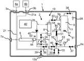
现在描述不同的APD系统1,这些不同的APD系统1使用FO来净化水并同时稀释PD浓缩流体。图4示出了具有分批PD流体产生的系统1。图5示出了与图4相同的系统,其中添加了使用流出物作为进给溶液来预稀释PD浓缩液的能力。图6示出了系统1,在该系统1中,来自第一PD浓缩液袋4a和第二PD浓缩液袋4b两者的PD浓缩液可以被引入第二流体管线22,使得可以利用第一泵41将一种或多种PD浓缩流体泵送到容器9。全部附图中相同的参考标记可能不会在文字上重复,但包括已经结合参考标记描述的所有结构、功能和替代方案。
图4中的系统1与用于产生用于PD的流体(包括经稀释的PD浓缩流体和最终的PD流体)的建议次序一起进行解释。对于与图1中的系统相同的部件,系统1具有相同的附图标记。此外,该系统包括第三泵43(在图1中以虚线显示),该第三泵43配置为控制一种或多种PD浓缩流体在第一流体管线21中的流速。第一流体管线21还设置有第一阀31,该第一阀31被布置成与在流体管线21a到第一流体管线21的连接点的上游的第一流体管线21一起操作。第二阀32被布置成与在流体管线21a到第一流体管线21的同一连接点的上游的流体管线21一起操作。第三泵43被布置成与在同一连接点下游的第一流体管线21一起操作。第三阀33被布置成与第六流体管线23一起操作。第六流体管线23布置在容器9的第一端口9a与第一流体管线21之间。第四阀34被布置成与在预处理单元8下游的第三流体管线25一起操作,并且布置在预处理单元8与进给侧6b的入口之间。第五阀35布置到在到第三流体管线25的连接点与到第四流体管线26的连接点之间的第七流体管线19。第十流体管线18布置在第七流体管线19与第二流体管线22之间。第六阀36被布置成与第十流体管线18一起操作。第七阀37被布置成与靠近出口连接器5a的第二流体管线22一起操作。第八阀38被布置成与来自容器9的泄压管线28一起操作。第九阀39被布置成与在到第四流体管线26和第十流体管线18的连接点下游的第七流体管线19一起操作。第九阀39控制到排放连接器12a的流动。
第五流体管线27流体连接到第二流体管线22和容器9的第二端口9b。因此,第五流体管线27连接第二流体管线22和容器9的第二端口9b。第十阀44被布置成与在到第十流体管线18的连接点与到第五流体管线27的连接点之间的第二流体管线22一起操作。第一泵41被布置成与第五流体管线27一起操作,而不是与如图1的系统中的第二流体管线22一起操作,以将流体泵送到容器9或从容器9泵送流体。加热器52被布置成与在容器9与第一泵41之间的第五流体管线27一起操作,但替代地,可以被布置为在流体路径2中的另一位置处加热流体。温度传感器53被布置成感测在加热器52下游的第五流体管线27中的流体的温度。在这里,浓度传感器51被布置成感测在第五流体管线27(这里在第一泵41与容器9之间)中的流体的浓度。The
第一压力传感器54被布置成感测在第一泵41与容器9之间的第五流体管线27中的压力。第二压力传感器55被布置成感测第二流体管线22中的压力,该压力是供应到出口连接器5a的最终的PD流体的压力。液位感测装置11被布置成感测容器9中的流体液位。例如,液位感测装置11包括模拟液位传感器。控制装置10被配置为控制第一再循环流体路径中的经稀释的PD浓缩流体,直到经稀释的PD浓缩流体的体积满足体积标准为止。可以利用液位传感器感测经稀释的PD浓缩液的体积或借助于用容积式第一泵41执行的泵冲程数来确定经稀释的PD浓缩液的体积。紫外线(UV)灯57可以布置在容器9内部以对容器9进行消毒。水电导率传感器56被布置成感测预处理单元8下游的水的电导率。The
使用图4中的系统1的建议的次序包括以下步骤中的一个或多个:The suggested sequence for using
1.启动自来水预处理。水连接器7a例如经由软管连接到自来水源。在该步骤期间,阀31、32、33、34、36、37、38和44是关闭的,而阀35和39是打开的。然后在预处理单元8中对水进行预处理,并利用水电导率传感器56感测电导率。1. Start the tap water pretreatment. The
2.将来自第一PD浓缩液袋4a的整个批次量的PD浓缩流体按体积投配到容器9。在该步骤期间,阀32、34、35、36、37、39、44是关闭的,而阀31、33、38是打开的。第三泵43从第一PD浓缩液袋4a泵送PD浓缩液。液位感测装置11感测容器9中的液位。2. Volumetrically dose the entire batch of PD concentrate fluid from the first
3.将来自第二PD浓缩液袋4b的整个批次量的PD浓缩流体按体积投配到容器9。在该步骤期间,阀31、34、35、36、37、39、44是关闭的,而阀32、33、38是打开的。第三泵43从第二PD浓缩液袋4b泵送PD浓缩液。液位感测装置11感测容器9中的液位。3. Volumetrically dose the entire batch of PD concentrate fluid from the second
4.利用水灌注FO过滤器,包括将经预处理的自来水泵送通过FO过滤器。在该步骤期间,阀31、32、33、35、36、37、38和44是关闭的,而阀34和39是打开的。在预处理单元8中对水进行预处理,利用水电导率传感器8感测电导率,并且利用第二泵42将经预处理的水泵送通过进给侧6b并通过排放连接器12a泵出。4. Prime the FO filter with water, including pumping pretreated tap water through the FO filter. During this step,
5.FO/混合期。将经预处理的自来水泵送通过FO单元6。利用第二泵42泵送的流速将是被传递到排放连接器12a的排出流(reject flow)。第一泵41正向运行以使容器9中的流体首先经由FO单元6、经由第三阀33然后返回容器9进行再循环。液位感测装置11和电导率传感器51关于不断变化的PD流体的体积和组成发展监测FO期(包括混合)。继续FO期,直到达到目标浓度(例如,目标电导率)为止。基于最终的PD流体中的目标渗透剂浓度计算来自第一PD浓缩液袋4a的经稀释的PD浓缩液的目标浓度。在该期过程中,阀31、32、35、36和37是关闭的,而阀33、34、38、39和44是打开的。在预处理单元8中对水进行预处理,利用水电导率传感器56感测经预处理的水的电导率,第二泵42提供进入进给侧6b的水流,第一泵41提供进入抽取侧6a的流速,液位感测装置11感测容器9中的液位,并且电导率传感器51感测电导率。5. FO/Mixing Period. The pretreated tap water is pumped through the
6.6.
a.跨膜泄压。由于FO单元6的水侧(进给侧6b)与PD流体侧(抽取侧6a)之间的剩余的浓度梯度,因此如果两侧保持刚性分离,则可能建立显著的跨膜压力。该压力可能损坏FO单元6或其周围的流体路径。通过打开抽取侧6a进行排放且打开进给侧进行预处理,进给侧与抽取侧之间的浓度差足够均匀以允许接近排空而不存在建立过高的跨膜压力的风险。在该步骤期间,阀31、32、33、35、37和38是关闭的,而阀34、36、39和44是打开的。a. Transmembrane pressure relief. Due to the remaining concentration gradient between the water side (feed
b.作为图6a的替代方案,可以通过将经稀释的浓缩液引到FO单元的进给侧以增加其浓度,从而减慢水提取过程来实现跨膜泄压。这用于两个目的;稀释过程被减慢并且可以更好地受控以达到目标稀释同时保持再循环并且随着水提取过程最终停止而避免跨膜压力建立。可以通过泵41经由阀34、35、36和/或通过阀33和34之间截留的抽取体积的FO膨胀来执行将经稀释的浓缩液引到进给侧。或者,可以出于相同目的引入流出物(图5)。通过控制进给侧的经稀释的浓缩液、流出物和经预处理的水的量,可以实现对水提取的微调。b. As an alternative to Figure 6a, transmembrane pressure relief can be achieved by introducing diluted concentrate to the feed side of the FO unit to increase its concentration, thereby slowing down the water extraction process. This serves two purposes; the dilution process is slowed down and can be better controlled to achieve the target dilution while maintaining recirculation and avoiding transmembrane pressure build-up as the water extraction process eventually stops. Introducing the diluted concentrate to the feed side can be performed by
7.传送PD流体。当浓度已经达到期望的浓度时,PD浓缩流体已经变得如此稀释,以致经稀释的PD浓缩流体具有如PD流体(现在称为最终的PD流体)的浓度。在该步骤期间,阀31、32、33、34、35、36、39、44是关闭的,而阀37、38是打开的。第一泵41提供PD流体从容器9到出口连接器5a的流动,并且利用第二压力传感器55感测压力。7. Deliver PD fluid. When the concentration has reached the desired concentration, the PD concentrate fluid has become so diluted that the diluted PD concentrate fluid has a concentration as PD fluid (now called final PD fluid). During this step,
8.排空FO单元6。FO单元6到容器9的排空可以通过沿相反方向泵送第一泵41来执行。在该步骤中,阀31、32、34、35、36、37、38、39是关闭的,而阀33、44是打开的。第一泵41和第一压力传感器54是可操作的。或者,可以在步骤7之前执行步骤8以也在抽取侧传送PD流体体积。通常,不要求按照列出的顺序执行这些步骤。8. Drain the
9.排空容器9。可以通过在正向方向上运行第一泵41来排空容器9。在该步骤期间,阀31、32、33、34、35和37是关闭的,而阀36、38、39和44是打开的。9.
10.至少重复一次步骤2到9。10. Repeat steps 2 through 9 at least once.
所提出的系统1可用于向患者、PD循环仪或PD流体容器提供PD流体。加热器52可用于对包括FO单元6和FO膜6c的系统1进行加热消毒。这使得能够重复使用FO膜6c。The proposed
图5示出了如图4中的系统1,另外,它还包括连接在入口连接器29a与第三流体管线25之间、进给侧6a的入口端口与第四阀34之间的第八流体管线29。因此,第八流体管线29流体连接入口连接器29a和进给侧6a的入口端口。流出物管线可以连接到入口连接器29a并且被布置成将来自患者的流出物传递到入口连接器29a中。然后流出物可以被用作进给溶液,如先前关于图2中的流程图所描述的。然后从流出物中提取水作为第一步骤执行以尽可能多地预稀释PD浓缩液。原水FO可用于继续稀释,直到达到PD流体组成为止。FIG. 5 shows the
图6示出了具有第一流体管线21和流体管线21a的替代布置的系统1。在该实施例中,第一流体管线21也连接到第二流体管线22与第五流体管线27之间的连接点。流体管线21a连接到第二流体管线22与第五流体管线27之间的同一连接点。然后一种或多种PD浓缩液可以通过反向(backwards)操作第一泵41以被供应到容器9。然后,如前所解释的,一种或多种PD浓缩液通过在正向方向上操作第一泵41被用作抽取溶液。在一些实施例中,来自第一流体袋4a的PD浓缩流体通过反向操作第一泵被供应到容器9。然后来自第一流体袋4a的PD浓缩流体被用作抽取溶液并变为稀释的。经稀释的PD浓缩流体在达到预定浓度时,可以被收集到容器9中。此后,第一泵41可以通过反向操作第一泵41从第二流体袋4b供应预定量的PD浓缩液。现在容器9中的流体可以通过在第一再循环流体路径61中再循环流体被混合,直到满足混合标准为止。混合标准可以包括浓度在一定时间内具有预定区间内的值。或者,混合腔室(未示出)流体地布置到在第五流体管线27与出口连接器5a之间的第二流体管线22。然后流体可以在其到达出口连接器5a的途中在混合腔室中被混合。Figure 6 shows the
上面描述的建议的次序分批产生PD流体。系统1还可用于利用一种或多种PD浓缩液和FO净化水在线产生PD流体。将PD浓缩液稀释至标称PD流体组成的基本原理与建议的次序相同,但用于产生PD流体的控制机制不同。不是再循环不断变化的经稀释的PD浓缩流体的批次直到在进给侧处从水中提取了足够的纯净水为止,而是在一种或多种PD浓缩液通过FO单元6的单程期间实现正确量的水提取(浓度稀释)。如果控制水提取率的一个或多个参数被控制,则这可以实现。这些参数包括但不限于:The suggested sequence described above produces PD fluid in batches.
1.FO单元6的进给侧6b与抽取侧6a之间的压力差。1. The pressure difference between the
2.表示进给侧6b和/或抽取侧6a处的流体温度的温度。2. The temperature representing the fluid temperature at the
3.水侧渗透压(排出流速)。3. Water side osmotic pressure (discharge flow rate).
4.PD浓缩液流速。4. PD concentrate flow rate.
如果PD流体到出口连接器5a的产生流速例如由用户或压力反馈控制,则PD浓缩液流速将确定PD流体的产生速率,因此不应用于水提取率控制。用于控制水提取率影响参数的反馈机制可以是例如浓度(电导率)。上述参数也可用于控制分批产生PD流体的水提取率。If the production flow rate of PD fluid to
可以执行从原水(例如,自来水)中进行水提取,直到水的渗透压达到进给侧6b与抽取侧6a之间的渗透压接近零并且不再可能进一步提取水的点。因此排出流被最小化,这意味着自来水消耗被最小化。这可以通过多种方式实现。在一个实施例中,执行PD流体的在线产生,其中进给溶液和抽取溶液在FO单元6中以逆流流动的方式供应,同时控制抽取溶液和进给溶液的流速以达到抽取侧出口处的PD流体组成和接近进给侧出口处的PD浓缩液渗透压。Water extraction from raw water (eg tap water) can be performed until the osmotic pressure of the water reaches a point where the osmotic pressure between the
在另一个实施例中,执行PD流体的批次产生。这里,在第一批次期间,新鲜的自来水体积在第二再循环流体路径62中被再循环,而PD浓缩流体体积在第一再循环流体路径61中被再循环,直到在抽取侧6a达到PD流体组成。如果初始的自来水体积被优化,则其在批次产生结束时的渗透压可以被最大化(以接近抽取侧6a的PD流体的渗透压)。在第二批次和即将到来的批次期间,剩余的水体积(接近PD流体渗透压)可以在第二批次产生的初始阶段期间被重新用于水提取,因为抽取溶液是高度浓缩的。这甚至还可以在水被排出之前使水的渗透压提高。然后,优化体积的新鲜的自来水被引入并再循环,以完成批次产生。因此,可以通过最大化废水渗透压来最小化水消耗。根据FO膜的特性,可接受的废水渗透压可能受到水侧结垢和/或在水侧聚集的化合物的前向通量的限制。由于沿着膜的总体流动(bulkflow)增加,在进给侧再循环水具有降低结垢风险的潜在优势。In another embodiment, batch production of PD fluid is performed. Here, during the first batch, the fresh tap water volume is recirculated in the second
图7和图8的系统1示出了替代实施例,其是产生最终的PD流体的在线实施例,该最终的PD流体被直接传送给患者或用于收集在储存容器中以供以后使用。在图7和图8中,流体未如图1(作为替代方案)和图4至图6中所做的那样在容器9中混合。图7和图8包括许多相同的组成,包括第一PD浓缩流体4a(例如,缓冲浓缩液)和第二PD浓缩流体4b(例如,渗透剂或葡萄糖浓缩液),它们分别经由PD浓缩液连接器3a和3b连接到系统1。在图7和图8中,为每个PD浓缩流体4a、4b设置单独的第三或浓缩液泵43a和43b。还设置了包括抽取侧和进给侧的正向渗透(FO)单元6。FO单元6的进给侧是进给侧再循环流体路径62的一部分,该进给侧再循环流体路径62还包括可与第四流体管线26以及阀34和35一起操作的第二或进给侧泵42。浓度(例如,电导率)传感器51、温度传感器53和加热器52设置在FO单元6的抽取侧的出口处。浓度(例如,电导率)传感器51和温度传感器53输出到控制单元40,该控制单元40使用电导率读数作为反馈,同时控制单元40使一种或多种浓缩液逐渐被添加或稀释,直到达到期望的电导率为止。控制单元40将温度读数用作电导率读数的补偿因子并用作用于控制施加到加热器52的功率量的反馈以实现期望的最终的PD流体温度(例如,37℃的体温)。The
图7和图8中的系统1的替代实施例还包括预处理单元8(其可以包括本文讨论的一些或所有结构、功能和替代方案),该预处理单元8用于预处理经由水连接器7a进入系统1的水。离开预处理单元8的水(i)经由阀35和39流动以经由排放连接器12a排放,或者(ii)经由阀34流动到FO单元6的进给侧。图7和图8中的控制装置10被配置为使得它可以将附加的经预处理的水从预处理单元8拉入进给侧中和/或从源4a和/或4b将一种(图8)或两种浓缩液(图7)拉入抽取侧中,其中,经预处理的水渗透跨过FO膜以稀释一种或多种浓缩液4a和/或4b。FO膜还进一步过滤和净化水,从而使其或确保其适用于PD处理。The alternative embodiment of the
图7和图8还包括用于控制患者泵送压力的出口阀37、出口连接器5a和压力传感器55。压力传感器55输出到控制单元40,该控制单元40使用压力读数作为反馈来控制泵42、43a和43b中的至少一个的速度,从而将患者的出口泵送压力设置在安全水平(例如,0.21巴(3psig)或更小)处。Figures 7 and 8 also include
图7和图8的系统1之间的差异包括如何引入PD浓缩流体4a和4b。在图7中,两种PD浓缩流体4a和4b(例如,缓冲液和葡萄糖)均被泵入FO单元6的抽取侧6a。这里,两种经稀释的浓缩流体均由浓度或电导率传感器51监测以得到反馈,从而使最终的PD流体达到期望的浓度或电导率。经由来自浓度或电导率传感器51的反馈控制的参数包括浓度泵43a和43b的速度和第二或进给侧水再循环泵42的速度中的任何一个或多个。Differences between the
在图8中,仅第一PD浓缩流体4a(例如,缓冲液)被泵入FO单元6的抽取侧,该第一PD浓缩流体4a由浓度或电导率传感器51监测以得到反馈,从而使PD流体达到第一PD浓缩流体(例如,缓冲液)的期望的浓度或电导率水平。而第二PD浓缩流体4b(例如,葡萄糖)被泵入FO单元6下游的第十流体管线18。第二PD浓缩流体4b在混合腔室60中与适当稀释的第一PD浓缩流体4a混合。混合腔室60可以是较小的容器(例如,50到100毫升,比容器9小),并与输出到控制单元40的一对液位传感器60a和60b一起操作,该控制单元40使用输出来保持在传感器之间的某处混合腔室60中PD流体的液位。流体还在第十流体管线18中进行混合,从而可能不需要混合腔室,例如,如图7中那样。混合腔室60还用作气体分离腔室或气体捕集器,因此可以在本文讨论的系统1的任何实施例中设置,用于进一步混合和/或气体分离。气体或PD流体可以从混合腔室60的顶部经由排气阀64排到排放连接器12a。In Figure 8, only the first
在图8中,在第二PD浓缩流体4b与经稀释的第一PD浓缩流体在混合腔室60中被混合之后,最终的PD流体被泵送通过第二或最终浓度或电导率传感器71,该第二或最终浓度或电导率传感器71输出到控制单元40。控制单元40询问来自最终电导率传感器71的输出以确保最终的PD流体具有期望的最终浓度或电导率。如果是这样,则控制单元40使第七或出口阀37打开,从而允许在安全的泵送压力下将适当混合和加热的最终的PD流体泵送到患者、循环仪或储存容器或袋中。如果不是这样,则控制单元40使旁通阀78打开,从而允许不适当混合的PF流体被传送到排放连接器12a。In Figure 8, after the second
如上面所讨论的,泵43a、43b和42中的至少一个的速度经由控制单元40进行控制,以便以期望的浓度或电导率(经由来自传感器51和可能的传感器71的反馈)和期望的压力(经由来自压力传感器55的反馈)将最终的PD流体传送给患者。因此,经由反馈被控制的每个泵43a、43b和42(一个或多个泵可以以设定速度运行)有两个反馈回路。为了防止反馈回路发生冲突,预想控制单元40设置最大速度以确保不超过患者压力限制,并将泵控制在这些最大速度内以实现期望的浓度或电导率。也就是说,浓度或电导率的反馈回路依赖于压力的反馈回路,因为压力回路设置速度限制,浓度或电导率反馈回路可以在该速度限制内改变浓度或电导率控制的速度。当最终的PD流体传送流量受压力控制时(例如,当直接传送给患者时),上述情况是正确的。然而当传送到循环仪或流体容器时,可以设置例如固定的传送流量,那么只有浓度反馈回路处于活动状态。As discussed above, the speed of at least one of the
对于系统1的任何版本,由第二或进给侧泵42和第三或浓度泵43产生的流速取决于可用的水体积和可用于水提取的时间。这些泵的较低流速提高了提取效率。泵42和43的流速还取决于FO单元6的尺寸。该单元的较大表面积提高了效率,这可以允许更高的流速。总体而言,确定效率的是原水或流出物流速、浓缩液流速和膜表面积的组合。For any version of the
在系统1的示例中,流出物提取和混合需要40分钟,产生等于或高于75ml/min的流出物流速。再次参考图1,如果可以替代地将大量流出物(例如,8到10升)保存在流出物的源30a中,并且将8到10升的经稀释的浓缩液储存在容器9中,那么将允许更长的FO期,产生大约15ml/min的流出物流速。这种FO期可以在处理期间和白天内执行,而无需其他活动。In the example of
在第一阶段中,系统1可以以非常有效的方式从流出物中提取水(例如通过降低流出物流量或增加跨膜压力(TMP))以产生经稀释的PD浓缩液。在第二阶段中,系统1可以使用少量例如自来水来进一步将经稀释的浓缩液稀释成最终经稀释的浓缩液。因此自来水消耗被最小化,并且无需永久连接水龙头。相反,患者可以在处理前将少量(例如,每次处理一升)的自来水添加到水箱(未示出)中。那么水箱是水源并连接到水连接器7a。在第一阶段中执行的从流出物中进行的水提取可以在当前暂停期间在来自先前排放的流出物体积上运行。此外,如果大量流出物(例如,8到10升)可以被保存在流出物的源30a中并且8到10升的经稀释的浓缩液被储存在容器9中,则从流出物中提取水的效率(从而节省自来水)可以被最大化,那么将允许更长的FO期,产生大约15ml/min的流出物流速。这种FO期可以在处理期间和白天内执行,而无需其他活动。In the first stage, the
还预期对于本文描述的系统1的任何版本,在FO单元6的进给侧6b与抽取侧6a之间保持跨膜压力梯度,其中进给侧压力大于抽取侧压力。这样做会提高FO单元6的水提取效率。任何地方的跨膜压力梯度或ΔP可能高于零巴到四巴(58psig)或更高,取决于FO单元6的制造商的规格和/或要求。一种产生较高的进给侧压力的方式为将图1中的第二泵42移动到第三流体管线25,使得正流体压力改为被施加到FO单元6的进给侧6b。控制第二泵42的速度从而控制进给侧压力。替代地或附加地,可以添加在控制单元40的控制下的可变限流器(未示出),以与第四流体管线26一起操作。这里控制单元40使可变限流器部分地阻塞管线26,从而在FO单元6的进给侧中产生增大的背压。第二泵42和限流器在本文中可称为加压设备。替代地或附加地,可以通过降低FO单元6的抽取侧6a上的压力来引起压力梯度。预期通过构造系统1以流体静力方式降低抽取侧压力,使得经稀释的PD浓缩液容器9相对于FO单元6处于高度较低的位置。It is also contemplated that for any version of the
替代地或附加地,可以通过加热或增加FO单元6的温度来提高提取效率。例如,如果期望具有更高的FO单元6温度,则可以沿着流出流体管线25放置附加的或替代的加热器(例如,预加热器(未示出)),该附加的或替代的加热器加热或提高FO单元6的温度。例如,任何地方的提高的流出物温度可以从略高于环境温度到50℃或可能更高,这取决于FO单元的制造商。选择流出物被加热到的温度,使得FO单元6转而被加热到期望的水平,并且还使得传送给患者的最终的PD流体可以被设置为大约体温或37℃。可以发现FO单元6用作散热器,使得即使流出物被加热到50℃,离开FO单元6的经稀释的浓缩液也低于50℃,因此仍然需要经由下游加热器14进行加热。在确定将流出物加热到的温度时,流出流体管线25中的结垢也是考虑因素,因为更高的温度可能增加结垢。通过加热FO单元6发生提取效率的提高的原因可能与跨FO膜6c的通量增加有关。Alternatively or additionally, the extraction efficiency can be increased by heating or increasing the temperature of the
因此,明确地预期本文讨论的系统1的任何版本来操纵、选择或设置膜表面积、进给侧和抽取侧流速、压力梯度ΔP或跨膜的跨膜压力和/或FO单元6的温度中的任何一个或多个,以实现期望的交换效率。这些变量与成本和易用性相平衡,以产生整体上理想的系统1。Therefore, any version of the
现在参考图9,本文描述的系统1的任何版本可以包括用于缓解与控制投配浓缩液有关的潜在问题的结构。特别地,在图1、图4和图5中,来自容器4b的浓缩液可能进入来自容器4a的浓缩液流,这意味着两种浓缩液在被添加时(或至少在一个投配步骤中)携带少量其他浓缩液。此外,第一次添加任何一种浓缩液时,管线21和/或管线21a中会有空气。Referring now to FIG. 9, any version of the
作为浓缩液污染问题的缓解措施,图9将每个浓缩液管线21、21a引向公共点P,管线21、21a与第一再循环流体路径61在该公共点P处相接。以这种方式,每个浓缩液4a、4b都有自己的路线到达第一再循环流体路径61,其中,再循环路径是混合体积的一部分。此外,第三或浓缩液泵43被移动到第一再循环流体路径61中,一旦浓缩液管线21、21a已被填满,这允许泵43添加控制单元40已经被编程添加的浓缩液量(不考虑泵的冲程容积误差)。此外,泵43经由延伸到泵43的任一侧的回路46与在控制单元的控制下的阀45并联放置,使得在稀释阶段流出FO单元6的流量是自由的,即,阀45使得能够自由流动通过再循环流体路径61。在一个实施例中,控制单元40使泵43在稀释阶段期间缓慢运行,使得在稀释阶段结束时,泵43和回路46填充与存在于经稀释的PD浓缩液容器9和再循环流体路径61中相同的流体。As a mitigation measure to the problem of contamination of the concentrate, FIG. 9 leads each
作为空气夹带问题的缓解措施,应注意,空气问题的严重程度取决于在PD流体的第一批次制备期间浓缩液4a或4b中存在的未净化的空气量以及通向点P的管线21和21a的尺寸。在图9中,在控制单元40的控制下的空气/流体传感器47(例如,电容或超声波传感器)直接放置在点P之后。控制单元40至少在PD流体的第一批次开始时使泵43泵送浓缩液4a、4b中的一个,直到传感器47检测到流体为止,然后切换到另一个浓缩液4a、4b并进行类似操作。管线21和21a以及再循环流体路径61通向传感器47的部分中的体积是已知的(或充分已知的)。因此,控制单元40可以通过计数泵43泵送的冲程来确定泵送的浓缩液4a和4b的体积(假设泵43是活塞或其他准确的容积泵,或者与流量计或秤结合的不太准确的泵)。As a mitigation measure for the air entrainment problem, it should be noted that the severity of the air problem depends on the amount of raw air present in
尽管已经结合当前被认为是最实用和优选的实施例描述了本发明,但是应当理解,本发明不限于公开的实施例,相反,本发明旨在覆盖包括在所附权利要求书的范围内的各种修改和等同布置。While the present invention has been described in connection with what are presently considered to be the most practical and preferred embodiments, it is to be understood that the invention is not limited to the disclosed embodiments, but on the contrary, the invention is intended to cover other aspects included within the scope of the appended claims. Various modifications and equivalent arrangements.
Claims (19)
Applications Claiming Priority (3)
| Application Number | Priority Date | Filing Date | Title |
|---|---|---|---|
| SE2050128 | 2020-02-06 | ||
| SE2050128-4 | 2020-02-06 | ||
| PCT/EP2021/052787WO2021156431A1 (en) | 2020-02-06 | 2021-02-05 | A system and method for producing fluid for peritoneal dialysis |
Publications (1)
| Publication Number | Publication Date |
|---|---|
| CN115066267Atrue CN115066267A (en) | 2022-09-16 |
Family
ID=74587010
Family Applications (1)
| Application Number | Title | Priority Date | Filing Date |
|---|---|---|---|
| CN202180013491.1APendingCN115066267A (en) | 2020-02-06 | 2021-02-05 | System and method for producing fluid for peritoneal dialysis |
Country Status (5)
| Country | Link |
|---|---|
| US (1) | US20230040372A1 (en) |
| EP (1) | EP4100077A1 (en) |
| JP (1) | JP7680459B2 (en) |
| CN (1) | CN115066267A (en) |
| WO (1) | WO2021156431A1 (en) |
Families Citing this family (1)
| Publication number | Priority date | Publication date | Assignee | Title |
|---|---|---|---|---|
| EP4626504A1 (en)* | 2022-11-29 | 2025-10-08 | Vantive Health GmbH | Medical fluid generation device |
Citations (6)
| Publication number | Priority date | Publication date | Assignee | Title |
|---|---|---|---|---|
| CN101155607A (en)* | 2005-02-16 | 2008-04-02 | 特莱奥美德股份公司 | System and method for regeneration of a fluid |
| WO2009083011A2 (en)* | 2007-12-30 | 2009-07-09 | Mohamed Fahim Khaled Mohamed T | A method for dialysis fluid regeneration |
| US20140217029A1 (en)* | 2013-02-01 | 2014-08-07 | Medtronic, Inc. | Fluid circuit for delivery of renal replacement therapies |
| US20170189599A1 (en)* | 2015-12-31 | 2017-07-06 | Baxter International Inc. | Methods and apparatuses using urea permselective diffusion through charged membranes |
| CN106975115A (en)* | 2017-03-09 | 2017-07-25 | 李建中 | Dialysate regeneration device, blood purification system |
| CN115023248A (en)* | 2020-01-28 | 2022-09-06 | 费森尤斯医疗护理德国有限责任公司 | Apparatus and method for preparing dialysate |
Family Cites Families (4)
| Publication number | Priority date | Publication date | Assignee | Title |
|---|---|---|---|---|
| JP2000107286A (en) | 1998-10-07 | 2000-04-18 | Akira Sakai | Perfusion apparatus for peritoneal dialyzate and perfusion method |
| DK179128B1 (en)* | 2014-02-24 | 2017-11-20 | Aquaporin As | Systems for utilizing the water content in fluid from a renal replacement therapy process |
| JP6575249B2 (en) | 2014-09-19 | 2019-09-18 | 東洋紡株式会社 | Artificial dialysate manufacturing method and artificial dialysate manufacturing system |
| CN112245691B (en)* | 2019-07-22 | 2024-07-05 | 巴克斯特医疗保健股份有限公司 | Method and system for preparing dialysate from raw water |
- 2021
- 2021-02-05CNCN202180013491.1Apatent/CN115066267A/enactivePending
- 2021-02-05WOPCT/EP2021/052787patent/WO2021156431A1/ennot_activeCeased
- 2021-02-05EPEP21704467.6Apatent/EP4100077A1/enactivePending
- 2021-02-05USUS17/797,952patent/US20230040372A1/enactivePending
- 2021-02-05JPJP2022548075Apatent/JP7680459B2/enactiveActive
Patent Citations (7)
| Publication number | Priority date | Publication date | Assignee | Title |
|---|---|---|---|---|
| CN101155607A (en)* | 2005-02-16 | 2008-04-02 | 特莱奥美德股份公司 | System and method for regeneration of a fluid |
| WO2009083011A2 (en)* | 2007-12-30 | 2009-07-09 | Mohamed Fahim Khaled Mohamed T | A method for dialysis fluid regeneration |
| US20140217029A1 (en)* | 2013-02-01 | 2014-08-07 | Medtronic, Inc. | Fluid circuit for delivery of renal replacement therapies |
| US20170189599A1 (en)* | 2015-12-31 | 2017-07-06 | Baxter International Inc. | Methods and apparatuses using urea permselective diffusion through charged membranes |
| CN106975115A (en)* | 2017-03-09 | 2017-07-25 | 李建中 | Dialysate regeneration device, blood purification system |
| CN115023248A (en)* | 2020-01-28 | 2022-09-06 | 费森尤斯医疗护理德国有限责任公司 | Apparatus and method for preparing dialysate |
| CN115038473A (en)* | 2020-01-28 | 2022-09-09 | 费森尤斯医疗护理德国有限责任公司 | Apparatus and method for preparing dialysate |
Also Published As
| Publication number | Publication date |
|---|---|
| EP4100077A1 (en) | 2022-12-14 |
| US20230040372A1 (en) | 2023-02-09 |
| JP2023512324A (en) | 2023-03-24 |
| WO2021156431A1 (en) | 2021-08-12 |
| JP7680459B2 (en) | 2025-05-20 |
Similar Documents
| Publication | Publication Date | Title |
|---|---|---|
| EP2101841B1 (en) | Blood treatment apparatus | |
| US8480609B2 (en) | Apparatus for extracorporeal blood treatment | |
| EP4178641B1 (en) | Thermal disinfection system for a medical apparatus | |
| JP7629932B2 (en) | System for producing a fluid for peritoneal dialysis - Patent application | |
| CN109200371B (en) | Body cavity liquid treatment device | |
| JPH0427485A (en) | Method for defoaming pure water and reverse osmosis method for production of pure water | |
| JP7680459B2 (en) | Systems and methods for producing peritoneal dialysis fluid - Patents.com | |
| JP7183006B2 (en) | Bodily fluid separation system and method of operating the bodily fluid separation system | |
| CN115087472B (en) | System and method for generating fluid for peritoneal dialysis | |
| CN115038473A (en) | Apparatus and method for preparing dialysate | |
| US12440614B2 (en) | System and method for producing fluid for peritoneal dialysis | |
| JP2004016675A (en) | Hemodialyzer | |
| JP7599303B2 (en) | Body cavity fluid treatment system and method of using the body cavity fluid treatment system | |
| US20240123129A1 (en) | Blood purification apparatus | |
| JP3353344B2 (en) | Hemodiafiltration equipment | |
| JPWO2021156429A5 (en) | ||
| JP2024128430A (en) | Blood purification device and blood purification system | |
| JPWO2021156431A5 (en) | ||
| JP2000126283A (en) | Apparatus for blood dialysis | |
| JPS6121105B2 (en) | ||
| JPH0337951B2 (en) |
Legal Events
| Date | Code | Title | Description |
|---|---|---|---|
| PB01 | Publication | ||
| PB01 | Publication | ||
| SE01 | Entry into force of request for substantive examination | ||
| SE01 | Entry into force of request for substantive examination |