CN115054358A - Active compression device, method of assembly and method of use - Google Patents
Active compression device, method of assembly and method of useDownload PDFInfo
- Publication number
- CN115054358A CN115054358ACN202210686291.9ACN202210686291ACN115054358ACN 115054358 ACN115054358 ACN 115054358ACN 202210686291 ACN202210686291 ACN 202210686291ACN 115054358 ACN115054358 ACN 115054358A
- Authority
- CN
- China
- Prior art keywords
- bone
- present
- screw
- distal
- axial
- Prior art date
- Legal status (The legal status is an assumption and is not a legal conclusion. Google has not performed a legal analysis and makes no representation as to the accuracy of the status listed.)
- Pending
Links
Images


Classifications
- A—HUMAN NECESSITIES
- A61—MEDICAL OR VETERINARY SCIENCE; HYGIENE
- A61B—DIAGNOSIS; SURGERY; IDENTIFICATION
- A61B17/00—Surgical instruments, devices or methods
- A61B17/56—Surgical instruments or methods for treatment of bones or joints; Devices specially adapted therefor
- A61B17/58—Surgical instruments or methods for treatment of bones or joints; Devices specially adapted therefor for osteosynthesis, e.g. bone plates, screws or setting implements
- A61B17/68—Internal fixation devices, including fasteners and spinal fixators, even if a part thereof projects from the skin
- A61B17/84—Fasteners therefor or fasteners being internal fixation devices
- A61B17/86—Pins or screws or threaded wires; nuts therefor
- A61B17/8685—Pins or screws or threaded wires; nuts therefor comprising multiple separate parts
- A—HUMAN NECESSITIES
- A61—MEDICAL OR VETERINARY SCIENCE; HYGIENE
- A61B—DIAGNOSIS; SURGERY; IDENTIFICATION
- A61B17/00—Surgical instruments, devices or methods
- A61B17/56—Surgical instruments or methods for treatment of bones or joints; Devices specially adapted therefor
- A61B17/58—Surgical instruments or methods for treatment of bones or joints; Devices specially adapted therefor for osteosynthesis, e.g. bone plates, screws or setting implements
- A61B17/68—Internal fixation devices, including fasteners and spinal fixators, even if a part thereof projects from the skin
- A61B17/686—Plugs, i.e. elements forming interface between bone hole and implant or fastener, e.g. screw
- A—HUMAN NECESSITIES
- A61—MEDICAL OR VETERINARY SCIENCE; HYGIENE
- A61B—DIAGNOSIS; SURGERY; IDENTIFICATION
- A61B17/00—Surgical instruments, devices or methods
- A61B17/56—Surgical instruments or methods for treatment of bones or joints; Devices specially adapted therefor
- A61B17/58—Surgical instruments or methods for treatment of bones or joints; Devices specially adapted therefor for osteosynthesis, e.g. bone plates, screws or setting implements
- A61B17/68—Internal fixation devices, including fasteners and spinal fixators, even if a part thereof projects from the skin
- A61B17/72—Intramedullary devices, e.g. pins or nails
- A61B17/7216—Intramedullary devices, e.g. pins or nails for bone lengthening or compression
- A61B17/7225—Intramedullary devices, e.g. pins or nails for bone lengthening or compression for bone compression
- A—HUMAN NECESSITIES
- A61—MEDICAL OR VETERINARY SCIENCE; HYGIENE
- A61B—DIAGNOSIS; SURGERY; IDENTIFICATION
- A61B17/00—Surgical instruments, devices or methods
- A61B17/56—Surgical instruments or methods for treatment of bones or joints; Devices specially adapted therefor
- A61B17/58—Surgical instruments or methods for treatment of bones or joints; Devices specially adapted therefor for osteosynthesis, e.g. bone plates, screws or setting implements
- A61B17/68—Internal fixation devices, including fasteners and spinal fixators, even if a part thereof projects from the skin
- A61B17/84—Fasteners therefor or fasteners being internal fixation devices
- A61B17/844—Fasteners therefor or fasteners being internal fixation devices with expandable anchors or anchors having movable parts
- A—HUMAN NECESSITIES
- A61—MEDICAL OR VETERINARY SCIENCE; HYGIENE
- A61B—DIAGNOSIS; SURGERY; IDENTIFICATION
- A61B17/00—Surgical instruments, devices or methods
- A61B17/56—Surgical instruments or methods for treatment of bones or joints; Devices specially adapted therefor
- A61B17/58—Surgical instruments or methods for treatment of bones or joints; Devices specially adapted therefor for osteosynthesis, e.g. bone plates, screws or setting implements
- A61B17/68—Internal fixation devices, including fasteners and spinal fixators, even if a part thereof projects from the skin
- A61B17/84—Fasteners therefor or fasteners being internal fixation devices
- A61B17/86—Pins or screws or threaded wires; nuts therefor
- A61B17/8605—Heads, i.e. proximal ends projecting from bone
- A61B17/861—Heads, i.e. proximal ends projecting from bone specially shaped for gripping driver
- A61B17/8615—Heads, i.e. proximal ends projecting from bone specially shaped for gripping driver at the central region of the screw head
- A—HUMAN NECESSITIES
- A61—MEDICAL OR VETERINARY SCIENCE; HYGIENE
- A61B—DIAGNOSIS; SURGERY; IDENTIFICATION
- A61B17/00—Surgical instruments, devices or methods
- A61B17/56—Surgical instruments or methods for treatment of bones or joints; Devices specially adapted therefor
- A61B17/58—Surgical instruments or methods for treatment of bones or joints; Devices specially adapted therefor for osteosynthesis, e.g. bone plates, screws or setting implements
- A61B17/68—Internal fixation devices, including fasteners and spinal fixators, even if a part thereof projects from the skin
- A61B17/84—Fasteners therefor or fasteners being internal fixation devices
- A61B17/86—Pins or screws or threaded wires; nuts therefor
- A61B17/8625—Shanks, i.e. parts contacting bone tissue
- A61B17/863—Shanks, i.e. parts contacting bone tissue with thread interrupted or changing its form along shank, other than constant taper
- A—HUMAN NECESSITIES
- A61—MEDICAL OR VETERINARY SCIENCE; HYGIENE
- A61B—DIAGNOSIS; SURGERY; IDENTIFICATION
- A61B17/00—Surgical instruments, devices or methods
- A61B17/56—Surgical instruments or methods for treatment of bones or joints; Devices specially adapted therefor
- A61B17/58—Surgical instruments or methods for treatment of bones or joints; Devices specially adapted therefor for osteosynthesis, e.g. bone plates, screws or setting implements
- A61B17/68—Internal fixation devices, including fasteners and spinal fixators, even if a part thereof projects from the skin
- A61B17/84—Fasteners therefor or fasteners being internal fixation devices
- A61B17/86—Pins or screws or threaded wires; nuts therefor
- A61B17/864—Pins or screws or threaded wires; nuts therefor hollow, e.g. with socket or cannulated
- A—HUMAN NECESSITIES
- A61—MEDICAL OR VETERINARY SCIENCE; HYGIENE
- A61B—DIAGNOSIS; SURGERY; IDENTIFICATION
- A61B17/00—Surgical instruments, devices or methods
- A61B17/56—Surgical instruments or methods for treatment of bones or joints; Devices specially adapted therefor
- A61B17/58—Surgical instruments or methods for treatment of bones or joints; Devices specially adapted therefor for osteosynthesis, e.g. bone plates, screws or setting implements
- A61B17/68—Internal fixation devices, including fasteners and spinal fixators, even if a part thereof projects from the skin
- A61B17/84—Fasteners therefor or fasteners being internal fixation devices
- A61B17/86—Pins or screws or threaded wires; nuts therefor
- A61B17/866—Material or manufacture
- A—HUMAN NECESSITIES
- A61—MEDICAL OR VETERINARY SCIENCE; HYGIENE
- A61B—DIAGNOSIS; SURGERY; IDENTIFICATION
- A61B17/00—Surgical instruments, devices or methods
- A61B17/56—Surgical instruments or methods for treatment of bones or joints; Devices specially adapted therefor
- A61B17/58—Surgical instruments or methods for treatment of bones or joints; Devices specially adapted therefor for osteosynthesis, e.g. bone plates, screws or setting implements
- A61B17/68—Internal fixation devices, including fasteners and spinal fixators, even if a part thereof projects from the skin
- A61B17/84—Fasteners therefor or fasteners being internal fixation devices
- A61B17/86—Pins or screws or threaded wires; nuts therefor
- A61B17/869—Pins or screws or threaded wires; nuts therefor characterised by an open form, e.g. wire helix
- A—HUMAN NECESSITIES
- A61—MEDICAL OR VETERINARY SCIENCE; HYGIENE
- A61B—DIAGNOSIS; SURGERY; IDENTIFICATION
- A61B17/00—Surgical instruments, devices or methods
- A61B17/56—Surgical instruments or methods for treatment of bones or joints; Devices specially adapted therefor
- A61B17/58—Surgical instruments or methods for treatment of bones or joints; Devices specially adapted therefor for osteosynthesis, e.g. bone plates, screws or setting implements
- A61B17/68—Internal fixation devices, including fasteners and spinal fixators, even if a part thereof projects from the skin
- A61B17/84—Fasteners therefor or fasteners being internal fixation devices
- A61B17/86—Pins or screws or threaded wires; nuts therefor
- A61B17/8695—Washers
- A—HUMAN NECESSITIES
- A61—MEDICAL OR VETERINARY SCIENCE; HYGIENE
- A61B—DIAGNOSIS; SURGERY; IDENTIFICATION
- A61B17/00—Surgical instruments, devices or methods
- A61B17/56—Surgical instruments or methods for treatment of bones or joints; Devices specially adapted therefor
- A61B17/58—Surgical instruments or methods for treatment of bones or joints; Devices specially adapted therefor for osteosynthesis, e.g. bone plates, screws or setting implements
- A61B17/88—Osteosynthesis instruments; Methods or means for implanting or extracting internal or external fixation devices
- A61B17/8875—Screwdrivers, spanners or wrenches
- A61B17/8877—Screwdrivers, spanners or wrenches characterised by the cross-section of the driver bit
- A61B17/888—Screwdrivers, spanners or wrenches characterised by the cross-section of the driver bit the driver bit acting on the central region of the screw head
- A—HUMAN NECESSITIES
- A61—MEDICAL OR VETERINARY SCIENCE; HYGIENE
- A61B—DIAGNOSIS; SURGERY; IDENTIFICATION
- A61B17/00—Surgical instruments, devices or methods
- A61B17/56—Surgical instruments or methods for treatment of bones or joints; Devices specially adapted therefor
- A61B17/58—Surgical instruments or methods for treatment of bones or joints; Devices specially adapted therefor for osteosynthesis, e.g. bone plates, screws or setting implements
- A61B17/88—Osteosynthesis instruments; Methods or means for implanting or extracting internal or external fixation devices
- A61B17/8875—Screwdrivers, spanners or wrenches
- A61B17/8886—Screwdrivers, spanners or wrenches holding the screw head
- A61B17/8888—Screwdrivers, spanners or wrenches holding the screw head at its central region
- A—HUMAN NECESSITIES
- A61—MEDICAL OR VETERINARY SCIENCE; HYGIENE
- A61B—DIAGNOSIS; SURGERY; IDENTIFICATION
- A61B17/00—Surgical instruments, devices or methods
- A61B17/56—Surgical instruments or methods for treatment of bones or joints; Devices specially adapted therefor
- A61B17/58—Surgical instruments or methods for treatment of bones or joints; Devices specially adapted therefor for osteosynthesis, e.g. bone plates, screws or setting implements
- A61B17/88—Osteosynthesis instruments; Methods or means for implanting or extracting internal or external fixation devices
- A61B17/8875—Screwdrivers, spanners or wrenches
- A61B17/8894—Screwdrivers, spanners or wrenches holding the implant into or through which the screw is to be inserted
- A—HUMAN NECESSITIES
- A61—MEDICAL OR VETERINARY SCIENCE; HYGIENE
- A61B—DIAGNOSIS; SURGERY; IDENTIFICATION
- A61B17/00—Surgical instruments, devices or methods
- A61B17/56—Surgical instruments or methods for treatment of bones or joints; Devices specially adapted therefor
- A61B17/58—Surgical instruments or methods for treatment of bones or joints; Devices specially adapted therefor for osteosynthesis, e.g. bone plates, screws or setting implements
- A61B17/68—Internal fixation devices, including fasteners and spinal fixators, even if a part thereof projects from the skin
- A61B2017/681—Alignment, compression, or distraction mechanisms
Landscapes
- Health & Medical Sciences (AREA)
- Orthopedic Medicine & Surgery (AREA)
- Life Sciences & Earth Sciences (AREA)
- Surgery (AREA)
- Medical Informatics (AREA)
- Engineering & Computer Science (AREA)
- Biomedical Technology (AREA)
- Heart & Thoracic Surgery (AREA)
- Nuclear Medicine, Radiotherapy & Molecular Imaging (AREA)
- Molecular Biology (AREA)
- Animal Behavior & Ethology (AREA)
- General Health & Medical Sciences (AREA)
- Public Health (AREA)
- Veterinary Medicine (AREA)
- Neurology (AREA)
- Surgical Instruments (AREA)
- Steroid Compounds (AREA)
Abstract
Translated fromChinese
Description
Translated fromChinese本申请是申请号为201780024562.1,申请日为2017年2月24日,发明名称为“主动压缩装置、组装方法和使用方法”的分案申请。This application is a divisional application with an application number of 201780024562.1, an application date of February 24, 2017, and the title of the invention is "active compression device, assembly method and use method".
相关申请Related applications
本申请要求名称为“Active Compression Apparatus,Methods of Assembly andMethods of Use”,2016年2月26日递交的美国临时申请序列号62/300,336的权益和优先权,在此将其全部内容通过引用并入本文。This application claims the benefit of and priority to U.S. Provisional Application Serial No. 62/300,336, entitled "Active Compression Apparatus, Methods of Assembly and Methods of Use", filed on February 26, 2016, the entire contents of which are hereby incorporated by reference This article.
技术领域technical field
本发明总体上涉及一般外科手术和骨科植入物,并且更具体地但非排他地,涉及植入以辅助骨融合和修复的装置。本发明涉及用于连接两个骨碎片的压缩装置,以及用于植入这种装置的相关装置,用于长时间压缩和/或固定骨碎片的方法,以及这种装置的制造。The present invention relates generally to surgical and orthopaedic implants, and more particularly, but not exclusively, to devices implanted to assist in bone fusion and repair. The present invention relates to a compression device for connecting two bone fragments, and related devices for implanting such a device, a method for compressing and/or fixing bone fragments over a long period of time, and the manufacture of such a device.
背景技术Background technique
通过融合定期治疗骨折和其他骨疾病。骨骼目前在植入物的帮助下融合,例如,针、杆、板和螺钉,其设计成在愈合发生时将骨或骨碎片保持在适当位置并且骨或骨块融合在一起。压缩可用于连接或稳定两个骨碎片并有助于骨碎片的愈合。压缩骨螺钉的实例在本领域中是已知的,每个都具有不同程度的功效。Fractures and other bone disorders are regularly treated with fusion. Bones are currently fused with the aid of implants, such as needles, rods, plates and screws, which are designed to hold the bone or bone fragments in place and the bones or pieces of bone fused together as healing occurs. Compression can be used to connect or stabilize the two bone fragments and aid in the healing of the bone fragments. Examples of compression bone screws are known in the art, each with varying degrees of efficacy.
关节融合术的目标是在预期的融合表面之间产生稳定的结合。尽管来自标准螺钉放置的压缩力在其应用期间是动态的,但是一旦拧紧螺钉,其作为静态装置起作用,不能像骨重建那样保持压缩载荷。保持在融合表面上的压缩载荷和应力屏蔽的减少可以帮助愈合。螺钉压缩的稳定性也可能受到几个因素的影响,例如骨密度、骨吸收和固定方向。可能需要具有一种装置,该装置在所需的融合部位上长时间传递主动或动态压缩以促进愈合。Bottlang,Michael PhD;Tsai,Stanley MS;Bliven,Emily K.BS;von Rechenberg,Brigitte DVM;Kindt,Philipp DVM;Augat,Peter PhD;Henschel,Julia BS;Fitzpatrick,Daniel C.MD;Madey,Steven M.MD Journal of Orthopaedic Trauma:February 2017-Volume 31-Issue 2-p 71–77(在此将其全部内容通过引用并入本文)进一步描述了这些优势的细节。The goal of arthrodesis is to produce a stable bond between the intended fusion surfaces. Although the compressive force from standard screw placement is dynamic during its application, once the screw is tightened, it acts as a static device that cannot hold the compressive load like bone reconstruction. A reduction in compressive loads and stress shielding that remains on the fusion surface can aid healing. The stability of screw compression may also be affected by several factors, such as bone density, bone resorption, and fixation orientation. It may be desirable to have a device that delivers active or dynamic compression over the desired fusion site for prolonged periods of time to promote healing. Bottlang, Michael PhD; Tsai, Stanley MS; Bliven, Emily K.BS; von Rechenberg, Brigitte DVM; Kindt, Philipp DVM; Augat, Peter PhD; Henschel, Julia BS; Fitzpatrick, Daniel C.MD; Madey, Steven M. Details of these advantages are further described in MD Journal of Orthopaedic Trauma: February 2017-Volume 31-Issue 2-p 71-77, which is hereby incorporated by reference in its entirety.
存在主动压缩螺钉概念。术语“主动”定义为在构件长度变化时具有一定的轴向张力能力。然而,这些概念具有复杂的外科手术规程。目前的主动压缩螺钉的概念受限于它们按照螺钉长度比例改变长度的能力,并且它们受到按照螺钉长度比例的轴向力的量的限制。目前的主动压缩螺钉概念不具有随时间调节压缩或具有可调压缩的能力。目前的主动压缩螺钉概念不具有简单的结构,使得制造复杂且昂贵,并且最终目前的平台不能按比例缩小到用于小骨头的治疗直径。因此,需要用于将骨融合在一起的改进的装置和方法。There is an active compression screw concept. The term "active" is defined as having some axial tension capability as the length of the member changes. However, these concepts have complex surgical procedures. The current concept of active compression screws is limited by their ability to change length proportional to the length of the screw, and they are limited by the amount of axial force proportional to the length of the screw. Current active compression screw concepts do not have or have the ability to adjust compression over time. The current active compression screw concept does not have a simple structure, making it complex and expensive to manufacture, and ultimately current platforms cannot be scaled down to treatment diameters for small bones. Therefore, there is a need for improved devices and methods for fusing bones together.
发明内容SUMMARY OF THE INVENTION
本发明涉及用于本文的物质的方法和装置,其涉及用于压缩合适材料的新型压缩装置、系统和方法。在某些实施例中,本发明涉及对用单一连续结构构建的骨段提供主动压缩的装置和方法。短语“单一连续结构”定义为由一块材料形成的结构,并且仅去除材料以产生最终构造,不需要连接独立组件或元件来创建最终构造。The present invention relates to methods and apparatus for use in the substances herein, and relates to novel compression apparatus, systems and methods for compressing suitable materials. In certain embodiments, the present invention relates to devices and methods for providing active compression to bone segments constructed from a single continuous structure. The phrase "single continuous structure" is defined as a structure formed from a piece of material and only removed to produce the final construction, without connecting separate components or elements to create the final construction.
短语“主动压缩”定义为在诸如轴向弹簧的构件的给定长度变化上的连续轴向张力。这种改变长度的能力可以在构件长度的1%-20%的范围内。相反,当长度变化超过构造的弹性极限时,标准螺钉不能提供轴向拉伸或压缩,该弹性极限通常是1%的小变形,本文定义为“被动压缩”。The phrase "active compression" is defined as continuous axial tension over a given change in length of a member such as an axial spring. This ability to change length can be in the range of 1%-20% of the length of the member. In contrast, standard screws cannot provide axial tension or compression when the length change exceeds the elastic limit of the construction, which is typically a small deformation of 1%, defined herein as "passive compression."
在本发明的某些实施例中,对骨段提供主动压缩的装置由两个或更多个构件构成。在某些实施例中,这些装置具有类似螺钉的特征。在某些实施例中,用于插入本发明装置的部署方法或外科手术过程类似于将类似螺钉的主体驱动到骨段中的方法,类似于常见的非主动压缩螺钉的方法。因为整个本发明的装置可能潜在地改变长度,所以在某些实施例中,装置可能潜在地提供有效主动压缩力的有效治疗范围或距离超过6mm,以便考虑到不同的骨吸收水平。促进结合所需的力的量将根据融合的解剖学特征而不同。本发明的方法和装置可以按比例缩放以适应0-200N的压缩轴向力范围并且可能更大,这取决于装置的直径。In certain embodiments of the present invention, the device for providing active compression to a bone segment consists of two or more members. In certain embodiments, these devices have screw-like features. In certain embodiments, the deployment method or surgical procedure used to insert the device of the present invention is similar to the method of driving a screw-like body into a bone segment, similar to the common method of non-actively compressing screws. Because the entire device of the present invention may potentially vary in length, in certain embodiments, the device may potentially provide an effective therapeutic range or distance over 6 mm of effective active compressive force to account for different levels of bone resorption. The amount of force required to promote bonding will vary depending on the anatomical features of the fusion. The method and device of the present invention can be scaled to accommodate a compressive axial force range of 0-200N and possibly larger, depending on the diameter of the device.
众所周知,施加所需施加力的时间段直到骨融合。在本发明的某些实施例中,提供了一种装置和方法,其中该装置向骨段提供主动压缩超过当前压缩螺钉的时间并且直到骨骼愈合或融合的时间。随着时间推移促进骨愈合所需的力的量可能会改变。然而,本发明允许调节结构变量,使得本发明的装置随时间和拉伸长度递送不同量的压缩轴向力。另外,可以调整这样的结构变量以在给定距离或时间内递送一致的力的量。本发明的装置具有按比例缩小到有效直径的能力,以用于直径可能小于2mm的手和脚的小骨头。It is well known that the required period of time to apply force is applied until the bone fuses. In certain embodiments of the present invention, a device and method are provided wherein the device provides active compression to a bone segment beyond the time currently compressing the screw and until the bone heals or fuses. The amount of force required to promote bone healing may change over time. However, the present invention allows adjustment of structural variables such that the devices of the present invention deliver different amounts of compressive axial force over time and stretched length. Additionally, such structural variables can be adjusted to deliver a consistent amount of force over a given distance or time. The device of the present invention has the ability to be scaled down to an effective diameter for use with small bones of the hands and feet that may be less than 2 mm in diameter.
根据本发明的轴向张力的激活可以在将装置部署到期望的解剖结构之前、期间或之后,从而允许开发和优化不同的外科手术规程以优化临床益处。为了便于首先部署引导销或K线然后在该构件上执行装置的递送的常见外科手术方法,本发明的装置可以是管状的。或者,本发明的装置可以是非管状或实心。本发明可以结合促进组织相互作用和压缩产生的所有其他已知的现有特征。Activation of axial tension in accordance with the present invention can be before, during or after deployment of the device to the desired anatomy, allowing different surgical procedures to be developed and optimized to optimize clinical benefit. To facilitate the common surgical approach of first deploying a guide pin or K-wire and then performing delivery of the device on that member, the device of the present invention may be tubular. Alternatively, the device of the present invention may be non-tubular or solid. The present invention can be combined with all other known existing features that promote tissue interaction and compression.
本发明的轴向张力以几种方式产生。可采用的一种方式是通过在装置主体内和沿装置主体使用穿孔或切割特征。这些特征可以变化,以提供给定应用的轴向拉伸力、扭转刚度和弯曲刚度的最佳标准。有几种方式可以将力加载到本发明的轴向拉伸构件中。其中之一是使螺钉状主体的螺纹产生轴向张力,该轴向张力在将主体插入骨段时加载构件以提供初始压缩和稳定。或者,可以采用传动机构将轴向力加载到装置中。该力还可以预加载有外部或内部或整个装置的保持机构,例如可以使用可再吸收的材料。如上所述,存在许多方式来产生、维持和释放轴向压缩力,从而促进执行递送本发明的治疗能量的许多程序变化。The axial tension of the present invention is generated in several ways. One way this can be done is through the use of perforation or cutting features in and along the device body. These characteristics can be varied to provide the best standard for axial tensile force, torsional stiffness, and bending stiffness for a given application. There are several ways in which forces can be loaded into the axial tensile member of the present invention. One of these is to create axial tension in the threads of the screw-like body, which loads the member to provide initial compression and stabilization when the body is inserted into the bone segment. Alternatively, a transmission mechanism can be used to load the axial force into the device. The force can also be preloaded with an external or internal or entire device retention mechanism, for example a resorbable material can be used. As noted above, there are many ways to generate, maintain, and release axial compressive force, thereby facilitating the implementation of many procedural variations for delivering the therapeutic energy of the present invention.
在本发明中,提供了装置和方法,其中由形状记忆合金(SMA,例如镍钛诺)构造的装置为骨段提供定制的主动轴向、扭转、弯曲、径向、剪切和/或压缩力。本发明涉及用于在植入时和植入之后的一段时间内压缩和/或张紧合适材料,特别是用于骨碎片的装置、系统和方法。In the present invention, devices and methods are provided wherein devices constructed from shape memory alloys (SMAs such as Nitinol) provide customized active axial, torsional, bending, radial, shear and/or compression to bone segments force. The present invention relates to devices, systems and methods for compressing and/or tensioning suitable materials, particularly bone fragments, during and for a period of time after implantation.
本发明还涉及连接构件,例如主动骨螺钉及其使用方法,用于固定组织和/或骨骼的部分,同时提供特定量的促进骨折或融合的更强愈合的所需弯曲或弹性,例如导致愈合的骨折或融合的扭转强度增加。本发明还涉及连接构件,例如主动杆和/或板及其使用方法,用于固定组织和/或骨头的部分,同时提供特定量的促进骨折或融合的更强愈合的所需弯曲或弹性,例如导致愈合的骨折或融合的扭转强度增加。The present invention also relates to connecting members, such as active bone screws, and methods of their use, for securing tissue and/or portions of bone while providing a specific amount of desired flexion or elasticity that promotes stronger healing of fractures or fusions, eg, resulting in healing increased torsional strength of fractures or fusions. The present invention also relates to connecting members, such as active rods and/or plates, and methods of use thereof, for immobilizing portions of tissue and/or bone while providing a specific amount of desired bending or elasticity to promote stronger healing of fractures or fusions, Such as increased torsional strength leading to a healed fracture or fusion.
所描述的发明可以与或不与骨科外伤板和/或髓内钉,和/或销、杆和/或外部固定装置一起使用。所描述的发明可以与实心螺钉、管状螺钉、带头螺钉和/或无头螺钉、杆、钉、板、U形钉、缝合锚钉和软组织锚固件一起使用。螺纹在本公开中通常描绘为组织锚定机构。然而,在装置的一个或多个端部上包括提供锚固的所有替代锚固机构也在本发明的范围内,包括但不限于扩张机构、交叉接合构件、粘固剂、粘合剂、缝合线以及骨科中常见的其他物质。The described invention may be used with or without orthopaedic trauma plates and/or intramedullary nails, and/or pins, rods and/or external fixation devices. The described invention can be used with solid, cannulated, headed and/or headless screws, rods, staples, plates, staples, suture anchors, and soft tissue anchors. Threads are generally depicted in this disclosure as tissue anchoring mechanisms. However, it is within the scope of the invention to include all alternative anchoring mechanisms that provide anchoring on one or more ends of the device, including, but not limited to, expansion mechanisms, cross-engaging members, cements, adhesives, sutures, and Other substances commonly found in orthopedics.
本发明还涉及连接构件,例如骨螺钉及其使用方法,用于将骨杆和/或板固定到组织和/或骨骼的一部分,同时提供特定量的促进骨折或融合的更强愈合的所需弯曲或弹性,例如导致愈合的骨折或融合的扭转强度增加。在某些实施例中,这种杆和/或板是非主动杆和/或板,并且本发明的主动连接构件为系统提供主动力或弯曲。在某些实施例中,这种杆和/或板是主动杆和/或板,并且本发明的主动杆和/或板以及主动连接构件都向系统提供主动力或弯曲。The present invention also relates to connecting members, such as bone screws, and methods of use thereof, for securing bone rods and/or plates to a portion of tissue and/or bone while providing the specific amount required to promote stronger healing of fractures or fusions Bending or elasticity, such as increased torsional strength leading to a healed fracture or fusion. In certain embodiments, such rods and/or plates are non-active rods and/or plates, and the active link members of the present invention provide active power or bending to the system. In certain embodiments, such rods and/or plates are active rods and/or plates, and both the active rods and/or plates of the present invention, as well as the active link members, provide active power or bending to the system.
本发明的某些实施例提供了一种用于生成主动压缩的装置,包括:远端骨接合部分;近端骨接合部分,其外径大于远端骨接合部分的外径;在近端骨接合部分和远端骨接合部分之间插入的中心部分,其具有穿过其形成的穿孔,这有利于装置尺寸的改变。其中该装置具有整体连续结构。其中装置是管状的。其中,近端骨接合部分包括螺纹,该螺纹的螺距不同于远端骨接合部分的螺纹的螺距。其中远端骨接合部分包括螺纹。其中穿孔包括不均匀的形状。其中穿孔包括螺旋形式。其中装置尺寸的变化包括长度的变化。其中装置尺寸的变化包括缩短装置的长度。其中装置尺寸的变化包括在大于12小时的时间段内装置尺寸的变化。Certain embodiments of the present invention provide a device for generating active compression, comprising: a distal bone engaging portion; a proximal bone engaging portion having an outer diameter greater than the outer diameter of the distal bone engaging portion; A central portion inserted between the engaging portion and the distal bone engaging portion has a perforation formed therethrough, which facilitates device size changes. Wherein the device has an integral continuous structure. wherein the device is tubular. Wherein, the proximal bone engaging portion includes threads having a different pitch than the threads of the distal bone engaging portion. Wherein the distal bone engaging portion includes threads. The perforations include non-uniform shapes. Wherein the perforation includes a helical form. Where changes in device dimensions include changes in length. Where the change in device size includes shortening the length of the device. Where the change in device size includes a change in device size over a time period greater than 12 hours.
本发明的某些实施例提供了一种用于产生主动压缩的装置,包括:具有压缩预载荷特征的管状主体;穿过管状主体的侧壁形成的多个穿孔;以及通过激活压缩预载荷特征在多个穿孔变形时改变的尺寸。其中,管状主体的侧壁的外部包括螺纹。其中尺寸包括装置的长度。其中,压缩预载荷特征包括多个螺纹,所述螺纹具有形成在管状主体的侧壁的外部上的不同螺距。其中激活包括装置的旋转。Certain embodiments of the present invention provide an apparatus for generating active compression, comprising: a tubular body having a compression preload feature; a plurality of perforations formed through a sidewall of the tubular body; and by activating the compression preload feature The size that changes when multiple perforations are deformed. Therein, the exterior of the side wall of the tubular body includes threads. The dimensions include the length of the device. Therein, the compression preload feature includes a plurality of threads having different pitches formed on the exterior of the sidewall of the tubular body. The activation includes rotation of the device.
本发明的某些实施例提供一种主动压缩骨段的方法,包括:通过穿过管状主体侧壁形成的穿孔的变形,将纵向拉伸应力施加到管状主体上;将管状主体插入第一骨段和第二骨段;并在一段时间内释放拉伸应力;并且通过释放拉伸应力来压缩第一骨段和第二骨段。其中,通过穿过管状主体侧壁形成的穿孔的变形将纵向拉伸应力施加到管状主体上和将管状主体插入第一骨段和第二骨段是同时发生的。其中,通过穿过管状主体侧壁形成的穿孔的变形将纵向拉伸应力施加到管状主体上包括旋转多个具有不同螺距的螺纹,所述螺纹形成在管状主体侧壁的外部上。其中,通过穿过管状主体侧壁形成的穿孔的变形将纵向拉伸应力施加到管状主体上包括拉长管状主体。Certain embodiments of the present invention provide a method of actively compressing a bone segment comprising: applying longitudinal tensile stress to a tubular body by deformation of a perforation formed through a sidewall of the tubular body; inserting the tubular body into a first bone and the second bone segment; and release the tensile stress for a period of time; and compress the first bone segment and the second bone segment by releasing the tensile stress. Therein, the application of longitudinal tensile stress to the tubular body by deformation of the perforations formed through the side walls of the tubular body and the insertion of the tubular body into the first bone segment and the second bone segment occur simultaneously. Wherein, applying longitudinal tensile stress to the tubular body by deformation of the perforations formed through the sidewall of the tubular body includes rotating a plurality of threads having different pitches formed on the exterior of the sidewall of the tubular body. Wherein, applying longitudinal tensile stress to the tubular body through deformation of a perforation formed through a sidewall of the tubular body includes elongating the tubular body.
本发明的某些实施例提供了一种用于产生主动压缩的装置,包括:近端锚固部分;远端锚固部分;多个支柱,其由在近端锚固部分和远端锚固部分之间插入的超弹性材料形成;第一状态,具有通过多个支柱的至少一个支柱的变形产生的轴向弹性势能;和第二状态,其中轴向弹性势能相对于位移非线性地释放,所述位移为近端锚固部分相对于远端锚固部分的位移。其中轴向弹性势能包括轴向拉伸弹性势能。其中轴向弹性势能包括轴向压缩弹性势能。其中,从第一状态到第二状态的转变包括多个支柱的至少一个支柱从高能状态到低能状态的转变。其中,从第一状态到第二状态的转变包括多个支柱的至少一个支柱从变形状态到未变形状态的转变。Certain embodiments of the present invention provide a device for generating active compression, comprising: a proximal anchor portion; a distal anchor portion; a plurality of struts inserted between the proximal anchor portion and the distal anchor portion A superelastic material is formed; a first state having axial elastic potential energy generated by deformation of at least one of the plurality of struts; and a second state wherein the axial elastic potential energy is released nonlinearly with respect to displacement, the displacement is Displacement of the proximal anchor portion relative to the distal anchor portion. The axial elastic potential energy includes axial tensile elastic potential energy. The axial elastic potential energy includes axial compression elastic potential energy. Wherein, the transition from the first state to the second state includes the transition of at least one strut of the plurality of struts from a high energy state to a low energy state. Wherein, the transition from the first state to the second state includes the transition of at least one strut of the plurality of struts from a deformed state to an undeformed state.
附图说明Description of drawings
本发明的实施例能够实现的这些和其他方面、特征和优点将是显而易见的,并从以下对本发明实施例的描述和参考附图中得以阐明,其中:These and other aspects, features and advantages that are enabled by embodiments of the present invention will be apparent from and elucidated from the following description of embodiments of the present invention with reference to the accompanying drawings, wherein:
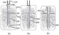
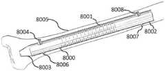
图1是根据本发明的一个方面的骨固定装置的侧视图,该骨固定装置插入处于非扩张状态的两个非缩小骨段中;1 is a side view of a bone fixation device inserted into two non-reduced bone segments in a non-expanded state, according to one aspect of the present invention;
图2是根据本发明的一个方面的骨固定装置的侧视图,该骨固定装置插入处于扩张拉紧状态的两个缩小骨段中;Figure 2 is a side view of a bone fixation device inserted into two reduced bone segments in an expanded tension state, according to one aspect of the present invention;
图3是根据本发明的一个方面的骨固定装置的侧视图,该骨固定装置插入处于非扩张状态的两个缩小骨段中;3 is a side view of a bone fixation device inserted into two reduced bone segments in a non-expanded state, according to one aspect of the present invention;
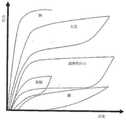
图4是描绘根据本发明的装置相对于标准螺钉随时间施加的压缩力的曲线图;4 is a graph depicting the compressive force exerted over time by a device according to the present invention relative to a standard screw;
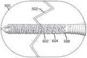
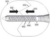
图5是根据本发明的一个方面的骨固定装置的侧视图,该骨固定装置插入处于扩张状态的两个非缩小骨段中;5 is a side view of a bone fixation device inserted into two non-reduced bone segments in an expanded state, according to one aspect of the present invention;
图6是根据本发明的一个方面的骨固定装置的侧视图,该骨固定装置插入处于非扩张状态的两个缩小骨段中;6 is a side view of a bone fixation device inserted into two reduced bone segments in a non-expanded state, according to one aspect of the present invention;
图7是根据本发明的一个方面的人体解剖结构中的示例性骨骼的图示,其中可以利用所公开的发明;7 is an illustration of an exemplary bone in human anatomy in which the disclosed invention may be utilized, according to one aspect of the present invention;
图8是根据本发明的一个方面的人手部解剖结构中的示例性骨骼的图示,其中可以利用所公开的发明;8 is an illustration of an exemplary bone in the anatomy of a human hand in which the disclosed invention may be utilized, according to one aspect of the present invention;
图9是根据本发明的一个方面的人足部解剖结构中的示例性骨骼的图示,其中可以利用所公开的发明;9 is an illustration of an exemplary bone in the anatomy of a human foot in which the disclosed invention may be utilized, according to one aspect of the present invention;
图10是根据本发明的一个方面的人足部解剖结构中的示例性骨骼的图示,其中可以利用所公开的发明;10 is an illustration of an exemplary bone in the anatomy of a human foot in which the disclosed invention may be utilized, according to one aspect of the present invention;
图11是根据本发明的一个方面的人体解剖结构中的示例性骨骼的图示,其中可以利用所公开的发明;11 is an illustration of an exemplary bone in human anatomy in which the disclosed invention may be utilized, according to one aspect of the present invention;
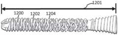
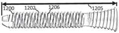
图12是根据本发明的一个方面的处于扩张状态的骨固定装置的侧视图;12 is a side view of a bone fixation device in an expanded state according to one aspect of the present invention;
图13是根据本发明的一个方面的处于非扩张状态的骨固定装置的侧视图;13 is a side view of a bone fixation device in a non-expanded state according to one aspect of the present invention;
图14是根据本发明的一个方面的处于扩张状态的骨固定装置的可变形或可扩张段的一部分的放大侧视图;14 is an enlarged side view of a portion of a deformable or expandable segment of a bone fixation device in an expanded state according to one aspect of the present invention;
图15是根据本发明的一个方面的处于非扩张状态的骨固定装置的可变形或可扩张段的一部分的放大侧视图;15 is an enlarged side view of a portion of a deformable or expandable segment of a bone fixation device in a non-expanded state according to one aspect of the present invention;
图16是根据本发明的一个方面的骨固定装置的主视图;16 is a front view of a bone fixation device according to an aspect of the present invention;
图17是根据本发明的一个方面的处于非扩张状态的骨固定装置的侧横截面图;17 is a side cross-sectional view of a bone fixation device in a non-expanded state according to one aspect of the present invention;
图18是根据本发明的一个方面的处于非扩张状态的骨固定装置的侧视图;18 is a side view of a bone fixation device in a non-expanded state according to one aspect of the present invention;
图19是根据本发明的一个方面的处于非扩张状态的骨固定装置的立体图;19 is a perspective view of a bone fixation device in a non-expanded state according to an aspect of the present invention;
图20是根据本发明的一个方面的处于扩张状态的骨固定装置的立体图;20 is a perspective view of a bone fixation device in an expanded state according to one aspect of the present invention;
图21是根据本发明的一个方面的骨固定装置的侧视图,该骨固定装置具有处于非扩张状态的无螺纹可扩张段;21 is a side view of a bone fixation device having an unthreaded expandable segment in a non-expanded state according to one aspect of the present invention;
图22是根据本发明的一个方面的骨固定装置的侧视图,该骨固定装置具有处于扩张状态的无螺纹可扩张段;22 is a side view of a bone fixation device having an unthreaded expandable segment in an expanded state, according to one aspect of the present invention;
图23是根据本发明的一个方面的骨固定装置的侧视图,该骨固定装置具有处于非扩张状态的无螺纹可扩张段;23 is a side view of a bone fixation device having an unthreaded expandable segment in a non-expanded state according to one aspect of the present invention;
图24是根据本发明的一个方面的骨固定装置的侧视图,该骨固定装置具有处于扩张状态的无螺纹可扩张段;24 is a side view of a bone fixation device having an unthreaded expandable segment in an expanded state, according to one aspect of the present invention;
图25是根据本发明的一个方面的骨固定组件的侧横截面图,该骨固定组件具有处于非扩张状态的带螺纹的可扩张段和带有带螺纹的中心构件的远端内螺纹;25 is a side cross-sectional view of a bone fixation assembly having a threaded expandable section in a non-expanded state and a distal internal thread with a threaded central member in accordance with one aspect of the present invention;
图26是根据本发明的一个方面的带螺纹的中心构件的侧视图;26 is a side view of a threaded center member according to an aspect of the present invention;
图27是根据本发明的一个方面的骨固定装置的放大侧横截面图,该骨固定装置具有处于未扩张状态的带螺纹的远端段;27 is an enlarged side cross-sectional view of a bone fixation device having a threaded distal segment in an unexpanded state according to one aspect of the present invention;
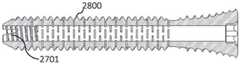
图28是根据本发明的一个方面的骨固定装置的侧横截面图,该骨固定装置具有处于非扩张状态的带螺纹的远端段;28 is a side cross-sectional view of a bone fixation device having a threaded distal segment in a non-expanded state according to one aspect of the present invention;
图29是根据本发明的一个方面的骨固定组件的立体图,该骨固定组件具有处于非扩张状态的带螺纹的可扩张段和带有带螺纹的中心构件和近端头保持夹头机构的远端内螺纹;29 is a perspective view of a bone fixation assembly having a threaded expandable section in a non-expanded state and a distal end with a threaded center member and a proximal head retaining collet mechanism in accordance with one aspect of the present invention end internal thread;
图30是根据本发明的一个方面的骨固定组件的侧横截面图,该骨固定组件具有处于非扩张状态的带螺纹的可扩张段和带有带螺纹的中心构件和近端头保持夹头机构的远端内螺纹;30 is a side cross-sectional view of a bone fixation assembly having a threaded expandable section and a threaded center member and proximal head retention collet in a non-expanded state according to one aspect of the present invention the distal internal thread of the mechanism;
图31是根据本发明的一个方面的骨固定组件的侧横截面图,该骨固定组件具有处于非扩张状态的带螺纹的可扩张段和具有带螺纹的中心构件和近端头保持夹头机构的远端内螺纹;31 is a side cross-sectional view of a bone fixation assembly having a threaded expandable section in a non-expanded state and having a threaded center member and a proximal head retention collet mechanism in accordance with one aspect of the present invention The distal internal thread of ;
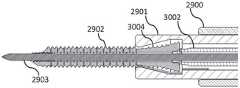
图32是根据本发明的一个方面的骨固定组件的立体图,该骨固定组件具有处于非扩张状态的带螺纹的可扩张段和具有带螺纹的中心构件和近端头保持驱动机构的远端内螺纹;32 is a perspective view of a bone fixation assembly having a threaded expandable segment in a non-expanded state and a distal inner portion having a threaded central member and a proximal head retention drive mechanism, according to one aspect of the present invention thread;
图33是根据本发明的一个方面的骨固定组件的侧横截面图,该骨固定组件具有处于非扩张状态的带螺纹的可扩张段和具有带螺纹的中心构件和近端头保持驱动机构的远端内螺纹;33 is a side cross-sectional view of a bone fixation assembly having a threaded expandable section in a non-expanded state and a threaded center member and proximal head retention drive mechanism in accordance with one aspect of the present invention Distal internal thread;
图34是根据本发明的一个方面的骨固定组件的一部分的侧横截面图,该骨固定组件具有处于非扩张状态的带螺纹的可扩张段和具有带螺纹的中心构件和近端头保持驱动机构的远端内螺纹;34 is a side cross-sectional view of a portion of a bone fixation assembly having a threaded expandable section in a non-expanded state and having a threaded center member and proximal head retention drive in accordance with one aspect of the present invention the distal internal thread of the mechanism;
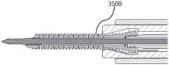
图35是根据本发明的一个方面的骨固定组件的侧横截面图,该骨固定组件具有处于非扩张状态的带螺纹的可扩张段和具有带螺纹的中心构件和近端头保持驱动机构以及近端头保持夹头机构的远端内螺纹;35 is a side cross-sectional view of a bone fixation assembly having a threaded expandable section in a non-expanded state and having a threaded central member and proximal head retention drive mechanism in accordance with one aspect of the present invention The proximal head retains the distal internal thread of the collet mechanism;
图36是根据本发明的一个方面的骨固定组件的侧横截面近视图,该骨固定组件具有处于非扩张状态的带螺纹的可扩张段和具有带螺纹的中心构件和近端头保持驱动机构以及近端头保持夹头机构的远端内螺纹;36 is a close-up side cross-sectional view of a bone fixation assembly having a threaded expandable segment in a non-expanded state and having a threaded center member and a proximal head retention drive mechanism in accordance with one aspect of the present invention and the distal internal thread of the proximal head retaining collet mechanism;
图37是根据本发明的一个方面的骨固定装置的立体图,该骨固定装置具有处于非扩张状态的无螺纹可扩张段;37 is a perspective view of a bone fixation device having an unthreaded expandable segment in a non-expanded state according to one aspect of the present invention;
图38是根据本发明的一个方面的骨固定装置的一部分的立体图,该骨固定装置具有处于扩张状态的无螺纹可扩张段;38 is a perspective view of a portion of a bone fixation device having an unthreaded expandable segment in an expanded state, according to an aspect of the present invention;
图39是根据本发明的一个方面的骨固定装置的一部分的立体图,该骨固定装置具有处于非扩张状态的无螺纹可扩张段;39 is a perspective view of a portion of a bone fixation device having an unthreaded expandable segment in a non-expanded state according to one aspect of the present invention;
图40是根据本发明的一个方面的骨固定组件的立体图,该骨固定组件具有处于非扩张状态的无螺纹可扩张段,中心构件具有远端和近端保持特征;40 is a perspective view of a bone fixation assembly having an unthreaded expandable segment in a non-expanded state and a central member having distal and proximal retention features, according to one aspect of the present invention;
图41是根据本发明的一个方面的具有远端和近端保持特征的中心构件的立体图;41 is a perspective view of a central member having distal and proximal retention features in accordance with one aspect of the present invention;
图42是根据本发明的一个方面的骨固定装置的侧视图,该骨固定装置具有处于非扩张状态的无螺纹可扩张段,具有远端和近端保持特征;42 is a side view of a bone fixation device having an unthreaded expandable segment in a non-expanded state with distal and proximal retention features, according to one aspect of the present invention;
图43是根据本发明的一个方面的骨固定装置的侧视图,该骨固定装置具有处于非扩张状态的无螺纹可扩张段,其具有中心外部加强构件;Figure 43 is a side view of a bone fixation device having an unthreaded expandable segment in a non-expanded state with a central outer reinforcing member in accordance with one aspect of the present invention;
图44是根据本发明的一个方面的骨固定装置的侧横截面图,该骨固定装置具有处于非扩张状态的无螺纹可扩张段,其具有中心外部加强构件;44 is a side cross-sectional view of a bone fixation device having an unthreaded expandable segment in a non-expanded state with a central outer reinforcing member in accordance with one aspect of the present invention;
图45是根据本发明的一个方面的骨固定装置的侧视图,该骨固定装置具有处于扩张状态的无螺纹可扩张段,其具有中心可溶解构件;45 is a side view of a bone fixation device having an unthreaded expandable segment in an expanded state with a central dissolvable member in accordance with one aspect of the present invention;
图46是根据本发明的一个方面的骨固定装置的侧横截面图,该骨固定装置具有处于扩张状态的无螺纹可扩张段,其具有中心可溶解构件;46 is a side cross-sectional view of a bone fixation device having an unthreaded expandable segment in an expanded state with a central dissolvable member in accordance with one aspect of the present invention;
图47是根据本发明的一个方面的具有近端头部保持机构的带螺纹的中心构件的侧视图;47 is a side view of a threaded center member with a proximal head retention mechanism in accordance with one aspect of the present invention;
图48是根据本发明的一个方面的骨固定组件的侧横截面图,该骨固定组件具有处于非扩张状态的无螺纹可扩张段和具有带有近端头保持机构的带螺纹的中心构件的近端内螺纹;48 is a side cross-sectional view of a bone fixation assembly having an unthreaded expandable section in a non-expanded state and a threaded center member with a proximal head retention mechanism in accordance with one aspect of the present invention Proximal internal thread;
图49是根据本发明的一个方面的骨固定组件的侧横截面近视图;该骨固定组件具有处于扩张状态的无螺纹可扩张段和具有带有近端头保持机构的带螺纹的中心管状构件的近端内螺纹;Figure 49 is a close-up side cross-sectional view of a bone fixation assembly having an unthreaded expandable section in an expanded state and a threaded central tubular member with a proximal head retention mechanism in accordance with one aspect of the present invention The proximal internal thread of ;
图50是根据本发明的一个方面的骨固定装置的侧横截面图,该骨固定装置具有处于非扩张状态的无螺纹可扩张段,其具有中心内部加强构件;50 is a side cross-sectional view of a bone fixation device having an unthreaded expandable segment in a non-expanded state with a central inner reinforcing member, according to one aspect of the present invention;
图51是根据本发明的一个方面的骨固定多组件装置的侧视图,该骨固定多组件装置具有处于非扩张状态的无螺纹可扩张段,其具有中心内部加强构件,不具有被捕获但可能自由旋转的近端头部构件;Figure 51 is a side view of a bone fixation multi-component device having an unthreaded expandable segment in a non-expanded state with a central inner reinforcement member without a captured but possible Freely rotating proximal head member;
图52是根据本发明的一个方面的骨固定多组件装置的侧横截面图,该骨固定多组件装置具有处于非扩张状态的无螺纹可扩张段,其具有中心内部加强构件,不具有被捕获但可能自由旋转的近端头部构件;52 is a side cross-sectional view of a bone fixation multi-component device having a non-threaded expandable segment in a non-expanded state with a central inner reinforcement member without a captured multi-component device according to one aspect of the present invention but may freely rotate the proximal head member;
图53是根据本发明的一个方面的骨固定多组件装置的侧视图,该骨固定多组件装置具有处于非扩张状态的无螺纹可扩张段,其具有中心内部加强构件和捕获但可能自由旋转的近端头部构件;53 is a side view of a bone fixation multi-component device having a non-threaded expandable segment in a non-expanded state with a central inner reinforcement member and a captured but possibly freely rotatable, according to one aspect of the present invention Proximal head member;
图54是根据本发明的一个方面的骨固定多组件装置的侧横截面图,该骨固定多组件装置具有处于非扩张状态的无螺纹可扩张段,其具有中心内部加强构件和捕获但可能自由旋转的近端头部构件;54 is a side cross-sectional view of a bone fixation multi-component device having an unthreaded expandable segment in a non-expanded state with a central inner reinforcement member and a captured but possibly free, according to one aspect of the present invention rotating proximal head member;
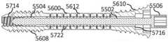
图55是根据本发明的一个方面的中心内部加强构件的立体图,该中心内部加强构件具有带螺纹的远端接合特征和近端头部构件;55 is a perspective view of a central inner reinforcement member having a threaded distal engagement feature and a proximal head member in accordance with one aspect of the present invention;
图56是根据本发明的一个方面的骨固定多组件装置的侧视图,该骨固定多组件装置具有处于扩张状态的无螺纹可扩张段,其具有带螺纹的远端接合特征;56 is a side view of a bone fixation multi-component device having an unthreaded expandable segment in an expanded state having a threaded distal engagement feature, according to one aspect of the present invention;
图57是根据本发明的一个方面的骨固定多组件装置的侧横截面图,该骨固定多组件装置具有处于扩张状态的无螺纹可扩张段,其中中心内部加强构件具有带螺纹的远端接合特征和近端头部构件;57 is a side cross-sectional view of a bone fixation multi-component device having an unthreaded expandable segment in an expanded state with a central inner reinforcement member having a threaded distal engagement according to one aspect of the present invention features and proximal head members;
图58是根据本发明的一个方面的骨固定多组件装置的侧横截面图,该骨固定多组件装置具有处于非扩张状态的无螺纹可扩张段,其中中心内部加强构件具有带螺纹的远端接合特征和近端头部构件;58 is a side cross-sectional view of a bone fixation multi-component device having an unthreaded expandable section in a non-expanded state with a central inner reinforcement member having a threaded distal end according to one aspect of the present invention engagement features and proximal head members;
图59是根据本发明的一个方面的骨固定多组件装置的侧视图,该骨固定多组件装置具有处于非扩张状态的无螺纹可扩张段,其中中心内部加强构件具有带螺纹的远端接合特征和近端头部构件;59 is a side view of a bone fixation multi-component device having an unthreaded expandable section in a non-expanded state with a central inner reinforcement member having a threaded distal engagement feature according to one aspect of the present invention and the proximal head member;
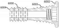
图60是根据本发明的一个方面的处于非扩张状态的骨固定装置的侧视图,该骨固定装置具有近端头部接合特征;Figure 60 is a side view of a bone fixation device in a non-expanded state having a proximal head engagement feature according to one aspect of the present invention;
图61是根据本发明的一个方面的处于非扩张状态的骨固定装置的侧横截面近视图,该骨固定装置具有近端头部接合特征;61 is a close-up side cross-sectional view of a bone fixation device in a non-expanded state having a proximal head engagement feature according to one aspect of the present invention;
图62是根据本发明的一个方面的处于非扩张状态的骨固定装置的立体图,该骨固定装置具有自由旋转的近端头部接合特征;62 is a perspective view of a bone fixation device in a non-expanded state with a freely rotating proximal head engagement feature according to one aspect of the present invention;
图63是根据本发明的一个方面的处于非扩张状态的骨固定装置的侧横截面近视图,该骨固定装置具有自由旋转的近端头部接合特征;63 is a close-up side cross-sectional view of a bone fixation device in a non-expanded state with a free-rotating proximal head engagement feature in accordance with one aspect of the present invention;
图64是根据本发明的一个方面的处于非扩张状态的骨固定装置的侧视图,该骨固定装置具有锥形小直径和可变螺距螺纹特征;Figure 64 is a side view of a bone fixation device in a non-expanded state having a tapered small diameter and variable pitch thread feature in accordance with one aspect of the present invention;
图65是根据本发明的一个方面的处于非扩张状态的骨固定装置的侧横截面图,该骨固定装置具有锥形小直径和可变螺距螺纹特征;65 is a side cross-sectional view of a bone fixation device in a non-expanded state having tapered small diameter and variable pitch thread features according to one aspect of the present invention;
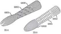
图66是根据本发明的一个方面的处于非扩张状态的骨固定装置的侧视图,该骨固定装置具有可变的小直径和大直径以及三导程螺距螺纹特征;66 is a side view of a bone fixation device in a non-expanded state having variable small and large diameters and three-lead thread features in accordance with one aspect of the present invention;
图67是根据本发明的一个方面的处于非扩张状态的骨固定装置的侧横截面图,该骨固定装置具有可变的小直径和大直径以及三导程螺距螺纹特征;67 is a side cross-sectional view of a bone fixation device in a non-expanded state having variable small and large diameters and three-lead thread features in accordance with one aspect of the present invention;
图68是根据本发明的一个方面的处于非扩张状态的骨固定装置的立体图,该骨固定装置具有可变的小直径和大直径以及三导程螺距螺纹特征;68 is a perspective view of a bone fixation device in a non-expanded state having variable small and large diameters and three-lead thread features in accordance with one aspect of the present invention;
图69是根据本发明的一个方面的处于无螺纹非扩张状态的骨固定装置的立体图,该骨固定装置具有可变的小直径和大直径以及远端三导程螺距螺纹和可变的近端螺纹特征;69 is a perspective view of a bone fixation device in an unthreaded, non-expanded state with variable minor and major diameters and distal three-lead threads and a variable proximal end according to one aspect of the present invention thread feature;
图70是根据本发明的一个方面的处于非扩张状态的骨固定装置的侧横截面图,该骨固定装置具有可变的小直径和大直径以及三导程螺距螺纹特征;70 is a side cross-sectional view of a bone fixation device in a non-expanded state having variable small and large diameters and three-lead thread features in accordance with one aspect of the present invention;
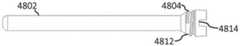
图71是根据本发明的一个方面的处于无螺纹非扩张状态的骨固定装置的侧横截面图,该骨固定装置具有可变的小直径和大直径以及远端三导程螺距螺纹和可变的近端螺纹特征;71 is a side cross-sectional view of a bone fixation device in an unthreaded, non-expanded state with variable minor and major diameters and distal three-lead threads and variable diameters according to one aspect of the present invention The proximal thread feature of ;
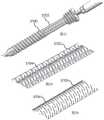
图72是根据本发明的一个方面的骨固定装置的立体图,该骨固定装置具有处于非扩张状态的无螺纹螺旋形可扩张段。72 is a perspective view of a bone fixation device having an unthreaded helical expandable segment in a non-expanded state, according to one aspect of the present invention.
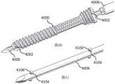
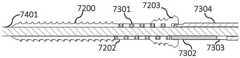
图73是根据本发明的一个方面的骨固定组件的立体图,该骨固定组件具有处于非扩张状态的无螺纹螺旋形可扩张段,其具有螺旋形扩张构件和驱动器;Figure 73 is a perspective view of a bone fixation assembly having an unthreaded helical expandable segment in a non-expanded state with a helical expansion member and a driver in accordance with one aspect of the present invention;
图74是根据本发明的一个方面的骨固定组件的立体图,该骨固定组件具有处于非扩张状态的无螺纹螺旋形可扩张段,其具有螺旋形扩张构件和驱动器和中心构件;Figure 74 is a perspective view of a bone fixation assembly having an unthreaded helical expandable segment in a non-expanded state with a helical expansion member and a driver and a central member in accordance with one aspect of the present invention;
图75是根据本发明的一个方面的骨固定组件的立体图,该骨固定组件具有处于扩张状态的无螺纹螺旋形可扩张段,其具有螺旋形扩张构件和驱动器和中心构件;Figure 75 is a perspective view of a bone fixation assembly having an unthreaded helical expandable segment in an expanded state with a helical expansion member and a driver and a central member, according to one aspect of the present invention;
图76是根据本发明的一个方面的骨固定组件的立体图,该骨固定组件具有处于扩张状态的无螺纹螺旋形可扩张段,其具有螺旋形扩张构件和驱动器和中心构件;Figure 76 is a perspective view of a bone fixation assembly having an unthreaded helical expandable segment in an expanded state with a helical expansion member and a driver and a central member, according to one aspect of the present invention;
图77是根据本发明的一个方面的骨固定组件的立体图,该骨固定组件具有处于扩张状态的无螺纹螺旋形可扩张段,其具有螺旋形扩张构件和驱动器;77 is a perspective view of a bone fixation assembly having an unthreaded helical expandable segment in an expanded state with a helical expansion member and a driver, according to one aspect of the present invention;
图78是根据本发明的一个方面的骨固定组件的立体图,该骨固定组件具有处于非扩张状态的无螺纹螺旋形可扩张段,其具有螺旋形扩张构件和驱动器;78 is a perspective view of a bone fixation assembly having an unthreaded helical expandable segment in a non-expanded state with a helical expansion member and a driver in accordance with one aspect of the present invention;
图79是根据本发明的一个方面的骨固定组件的侧横截面图,该骨固定组件具有处于扩张状态的无螺纹螺旋形可扩张段,其具有螺旋形扩张构件和驱动器和中心构件;Figure 79 is a side cross-sectional view of a bone fixation assembly having an unthreaded helical expandable segment in an expanded state with a helical expansion member and a driver and a central member in accordance with one aspect of the present invention;
图80是根据本发明的一个方面的骨固定组件的立体图,该骨固定组件具有处于非扩张状态的无螺纹可扩张段,其在骨中具有跨轴接合构件;Figure 80 is a perspective view of a bone fixation assembly having an unthreaded expandable segment in a non-expanded state with a transaxial engagement member in the bone, according to one aspect of the present invention;
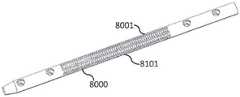
图81是根据本发明的一个方面的骨固定组件的立体图,该骨固定组件具有处于非扩张状态的无螺纹可扩张段;Figure 81 is a perspective view of a bone fixation assembly having an unthreaded expandable segment in a non-expanded state according to one aspect of the present invention;
图82是根据本发明的一个方面的骨固定组件的立体图,该骨固定组件具有处于扩张状态的无螺纹可扩张段;82 is a perspective view of a bone fixation assembly having an unthreaded expandable segment in an expanded state, according to one aspect of the present invention;
图83是根据本发明的一个方面的骨固定组件的侧横截面图,该骨固定组件具有处于非扩张状态的无螺纹可扩张段,其具有中心构件;Figure 83 is a side cross-sectional view of a bone fixation assembly having a non-threaded expandable section in a non-expanded state with a central member in accordance with one aspect of the present invention;
图84是根据本发明的一个方面的骨固定组件的侧视图,该骨固定组件具有处于非扩张状态的无螺纹可扩张段,其具有中心构件;Figure 84 is a side view of a bone fixation assembly having a non-threaded expandable section in a non-expanded state with a central member in accordance with one aspect of the present invention;
图85是根据本发明的一个方面的骨固定组件的侧横截面图,该骨固定组件具有处于扩张状态的无螺纹可扩张段,其具有中心构件和保持特征;85 is a side cross-sectional view of a bone fixation assembly having an unthreaded expandable segment in an expanded state with a central member and retention features, according to one aspect of the present invention;
图86是根据本发明的一个方面的骨固定组件的端视图,该骨固定组件具有处于扩张状态的无螺纹可扩张段,其具有中心构件和保持特征;Figure 86 is an end view of a bone fixation assembly having an unthreaded expandable segment in an expanded state with a central member and retention features, according to one aspect of the present invention;
图87是根据本发明的一个方面的骨固定组件的侧横截面图,该骨固定组件具有处于扩张状态的无螺纹可扩张段,其具有中心构件和保持特征;87 is a side cross-sectional view of a bone fixation assembly having an unthreaded expandable segment in an expanded state with a central member and retention features, according to one aspect of the present invention;
图88是根据本发明的一个方面的骨固定装置的一部分的侧视图,该骨固定装置具有处于非扩张状态的无螺纹可扩张段;88 is a side view of a portion of a bone fixation device having an unthreaded expandable segment in a non-expanded state, according to an aspect of the present invention;
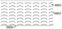
图89是根据本发明的一个方面的骨固定装置的切割槽图案的一部分的局部侧视图,该骨固定装置具有处于非扩张状态的无螺纹可扩张段;89 is a partial side view of a portion of a cutting slot pattern of a bone fixation device having an unthreaded expandable segment in a non-expanded state according to one aspect of the present invention;
图90是根据本发明的一个方面的骨固定装置的切割槽图案的一部分的局部侧视图,该骨固定装置具有处于非扩张状态的无螺纹可扩张段;90 is a partial side view of a portion of a cutting slot pattern of a bone fixation device having an unthreaded expandable segment in a non-expanded state according to one aspect of the present invention;
图91是根据本发明的一个方面的骨固定装置的一部分的侧视图,该骨固定装置具有处于扩张状态的无螺纹可扩张段;Figure 91 is a side view of a portion of a bone fixation device having an unthreaded expandable segment in an expanded state, according to one aspect of the present invention;
图92是根据本发明的一个方面的骨固定装置的切割槽图案的一部分的局部侧视图,该骨固定装置具有处于扩张状态的无螺纹可扩张段;92 is a partial side view of a portion of a cutting slot pattern of a bone fixation device having an unthreaded expandable segment in an expanded state, according to one aspect of the present invention;
图93是根据本发明的一个方面的骨固定装置的切割槽图案的一部分的局部侧视图,该骨固定装置具有处于扩张状态的无螺纹可扩张段;93 is a partial side view of a portion of a cutting slot pattern of a bone fixation device having an unthreaded expandable segment in an expanded state, according to one aspect of the present invention;
图94是根据本发明的一个方面的骨固定装置的切割槽图案的一部分的局部侧视图,该骨固定装置具有处于扩张状态的无螺纹可扩张段;94 is a partial side view of a portion of a cutting slot pattern of a bone fixation device having an unthreaded expandable segment in an expanded state, according to one aspect of the present invention;
图95是根据本发明的一个方面的骨固定装置的切割槽图案的一部分的局部侧视图,该骨固定装置具有处于非扩张状态的无螺纹可扩张段;95 is a partial side view of a portion of a cutting slot pattern of a bone fixation device having an unthreaded expandable segment in a non-expanded state according to one aspect of the present invention;
图96是根据本发明的一个方面的骨固定装置的切割槽图案的一部分的局部侧视图,该骨固定装置具有处于非扩张状态的无螺纹可扩张段;96 is a partial side view of a portion of a cutting slot pattern of a bone fixation device having an unthreaded expandable segment in a non-expanded state according to one aspect of the present invention;
图97是根据本发明的一个方面的骨固定装置的切割槽图案的一部分的局部侧视图,该骨固定装置具有处于非扩张状态的无螺纹可扩张段;97 is a partial side view of a portion of a cutting slot pattern of a bone fixation device having an unthreaded expandable segment in a non-expanded state according to one aspect of the present invention;
图98是根据本发明的一个方面的骨固定装置的切割槽图案的一部分的局部侧视图,该骨固定装置具有处于非扩张状态的无螺纹可扩张段;98 is a partial side view of a portion of a cutting slot pattern of a bone fixation device having an unthreaded expandable segment in a non-expanded state according to one aspect of the present invention;
图99是根据本发明的一个方面的骨固定装置的切割槽图案的一部分的局部侧视图,该骨固定装置具有处于非扩张状态的无螺纹可扩张段;99 is a partial side view of a portion of a cutting slot pattern of a bone fixation device having an unthreaded expandable segment in a non-expanded state according to one aspect of the present invention;
图100是根据本发明的一个方面的骨固定装置的侧视图,该骨固定装置具有处于非扩张状态的无螺纹螺旋形可扩张段;Figure 100 is a side view of a bone fixation device having an unthreaded helical expandable segment in a non-expanded state according to one aspect of the present invention;
图101是根据本发明的一个方面的骨固定装置的侧横截面图,该骨固定装置具有处于非扩张状态的非螺纹螺旋形可扩张段;101 is a side cross-sectional view of a bone fixation device having a non-threaded helical expandable segment in a non-expanded state according to one aspect of the present invention;
图102是根据本发明的一个方面的具有无螺纹段的骨固定装置的侧视图;102 is a side view of a bone fixation device with unthreaded segments according to one aspect of the present invention;
图103是显示根据本发明的一个方面的材料应变曲线的曲线图;Figure 103 is a graph showing a material strain curve according to one aspect of the present invention;
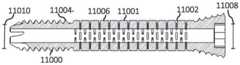
图104是根据本发明的一个方面的骨固定装置的透视放大视图,该骨固定装置具有处于非扩张状态的三导程螺纹可扩张段;104 is an enlarged perspective view of a bone fixation device having a three-lead threaded expandable segment in a non-expanded state according to one aspect of the present invention;
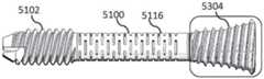
图105是根据本发明的一个方面的具有单导程螺纹段的骨固定装置的侧视图和放大端视图;105 is a side view and an enlarged end view of a bone fixation device having a single lead threaded segment according to one aspect of the present invention;
图106是根据本发明的一个方面的具有双导程螺纹段的骨固定装置的侧视图和放大端视图;106 is a side view and an enlarged end view of a bone fixation device having a double lead threaded segment according to one aspect of the present invention;
图107是根据本发明的一个方面的具有三导程螺纹段的骨固定装置的侧视图和放大端视图;107 is a side view and an enlarged end view of a bone fixation device having a three-lead threaded segment according to one aspect of the present invention;
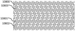
图108是根据本发明的一个方面的骨固定装置的切割槽图案的一部分的平面放大图,该骨固定装置具有处于非扩张状态的非螺纹可扩张段,该段会产生两种不同的图案,包裹在身体环境周围;Figure 108 is an enlarged plan view of a portion of a cutting slot pattern of a bone fixation device having a non-threaded expandable segment in a non-expanded state that produces two different patterns, according to one aspect of the present invention, wrapped around the physical environment;
图109是根据本发明的一个方面的骨固定装置的连接特征的放大正视图,该骨固定装置具有处于连接状态的无螺纹可扩张段和螺纹段;109 is an enlarged front view of a connection feature of a bone fixation device having an unthreaded expandable segment and a threaded segment in a connected state, according to one aspect of the present invention;
图110是根据本发明的一个方面的骨固定装置的侧视图,该骨固定装置具有处于非扩张状态的无螺纹可扩张段,该段的直径大于螺纹部分的小直径;110 is a side view of a bone fixation device having an unthreaded expandable segment in a non-expanded state, the segment having a diameter greater than the minor diameter of the threaded portion, according to one aspect of the present invention;
图111是根据本发明的一个方面的骨固定装置的侧横截面图,该骨固定装置具有处于非扩张状态的无螺纹可扩张段,该段的直径大于螺纹部分的小直径;111 is a side cross-sectional view of a bone fixation device having an unthreaded expandable segment in a non-expanded state, the segment having a diameter greater than the minor diameter of the threaded portion, according to one aspect of the present invention;
图112是根据本发明的一个方面的骨固定装置的侧视图,该骨固定装置具有处于非扩张状态的无螺纹可扩张段,该段与螺纹部分的轴线偏离轴线弯曲;112 is a side view of a bone fixation device having an unthreaded expandable segment in a non-expanded state, the segment being bent off-axis from the axis of the threaded portion, according to one aspect of the present invention;
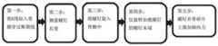
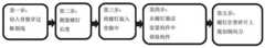
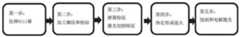
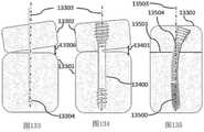
图113是显示根据本发明的骨固定装置的临床应用方法的一个实施例的流程图;Figure 113 is a flow chart showing one embodiment of a clinical application method of the bone fixation device according to the present invention;
图114是显示根据本发明的骨固定装置的临床应用方法的一个实施例的流程图;Figure 114 is a flow chart showing one embodiment of a clinical application method of the bone fixation device according to the present invention;
图115是显示根据本发明的骨固定装置的临床应用方法的一个实施例的流程图;Figure 115 is a flow chart showing one embodiment of a clinical application method of the bone fixation device according to the present invention;
图116是显示根据本发明的骨固定装置的临床应用方法的一个实施例的流程图;Figure 116 is a flow chart showing one embodiment of a clinical application method of the bone fixation device according to the present invention;
图117是显示根据本发明的骨固定装置的临床应用方法的一个实施例的流程图;Figure 117 is a flow chart showing one embodiment of a clinical application method of the bone fixation device according to the present invention;
图118是显示根据本发明的骨固定装置的临床应用方法的一个实施例的流程图;Figure 118 is a flow chart showing one embodiment of a clinical application method of the bone fixation device according to the present invention;
图119是显示根据本发明的制造骨固定装置的方法的一个实施例的流程图;Figure 119 is a flow chart showing one embodiment of a method of manufacturing a bone fixation device according to the present invention;
图120是显示根据本发明的制造骨固定装置的方法的一个实施例的流程图;Figure 120 is a flow chart showing one embodiment of a method of manufacturing a bone fixation device according to the present invention;
图121是显示根据本发明的制造骨固定装置的方法的一个实施例的流程图;Figure 121 is a flow chart showing one embodiment of a method of manufacturing a bone fixation device according to the present invention;
图122是显示根据本发明的制造骨固定装置的方法的一个实施例的流程图;Figure 122 is a flow chart showing one embodiment of a method of manufacturing a bone fixation device according to the present invention;
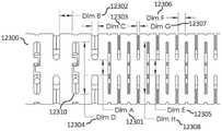
图123是根据本发明的一个方面的骨固定装置的局部侧视图,该骨固定装置在非扩张状态下具有多种膨胀特性的无螺纹可扩张段;123 is a partial side view of a bone fixation device having a non-threaded expandable segment with various expansion characteristics in a non-expanded state according to one aspect of the present invention;
图124是根据本发明的一个方面的骨固定装置的局部侧视图,该骨固定装置在具有变形控制特征的非扩张状态下具有多个膨胀特性的无螺纹可扩张段;124 is a partial side view of a bone fixation device having a plurality of unthreaded expandable segments with expansion characteristics in a non-expanded state with deformation control features, according to one aspect of the present invention;
图125是根据本发明的一个方面的骨固定装置的侧视图,该骨固定装置在非扩张状态下具有多种膨胀特性的无螺纹可扩张段;125 is a side view of a bone fixation device having a non-threaded expandable segment with various expansion properties in a non-expanded state, according to one aspect of the present invention;
图126是根据本发明的一个方面的骨固定装置的侧视图,该骨固定装置在非扩张状态下具有径向扩张特性的无螺纹可扩张段;126 is a side view of a bone fixation device having an unthreaded expandable segment with radial expansion properties in a non-expanded state, according to one aspect of the present invention;
图127是根据本发明的一个方面的骨固定装置的侧视图,该骨固定装置在部分扩张状态下具有径向扩张特性的无螺纹可扩张段;127 is a side view of a bone fixation device having an unthreaded expandable segment with radial expansion properties in a partially expanded state, according to one aspect of the present invention;
图128是根据本发明的一个方面的骨固定装置的侧视图,该骨固定装置在完全扩张状态下具有径向扩张特性的无螺纹可扩张段;128 is a side view of a bone fixation device having an unthreaded expandable segment with radial expansion characteristics in a fully expanded state, according to one aspect of the present invention;
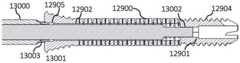
图129是根据本发明的一个方面的骨固定装置的侧横截面图,该骨固定装置具有处于非扩张状态的螺纹远端段和无螺纹可扩张段,可扩张段的直径大于螺纹部分的小直径,远端段具有内径上的特征,该特征可以接合并传递扭矩和轴向载荷;129 is a side cross-sectional view of a bone fixation device having a threaded distal segment in a non-expanded state and an unthreaded expandable segment, the expandable segment having a diameter greater than a small diameter of the threaded portion, according to one aspect of the present invention Diameter, the distal segment has features on the inner diameter that can engage and transmit torque and axial loads;
图130是根据本发明的一个方面的骨固定装置组件的侧横截面图,该骨固定装置组件具有处于非扩张状态的螺纹远端段和无螺纹可扩张段,可扩张段的直径大于带螺纹的远端段的小直径,远端段具有内径上的特征,该特征可以接合并传递扭矩和轴向载荷,以及驱动机构,其可以接合装置的远端特征和近端;130 is a side cross-sectional view of a bone fixation device assembly having a threaded distal section in a non-expanded state and an unthreaded expandable section, the expandable section having a larger diameter than the threaded, according to one aspect of the present invention the small diameter of the distal segment, the distal segment having features on the inner diameter that can engage and transmit torque and axial loads, and a drive mechanism that can engage the distal and proximal ends of the device;
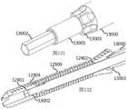
图131是根据本发明的一个方面的具有驱动机构的装置组件的立体图,该驱动机构接合装置的远端特征和近端;以及Figure 131 is a perspective view of a device assembly having a drive mechanism that engages a distal feature and a proximal end of the device in accordance with one aspect of the present invention; and
图132是根据本发明的一个方面的骨固定装置组件的透视横截面图,该骨固定装置组件具有处于非扩张状态的螺纹远端段和无螺纹可扩张段,可扩张段的直径大于带螺纹的远端段的小直径,远端段具有内径上的特征,该特征可以接合并传递扭矩和轴向载荷,以及驱动机构,其可以接合装置的远端特征和近端;132 is a perspective cross-sectional view of a bone fixation device assembly having a threaded distal section in a non-expanded state and an unthreaded expandable section, the expandable section having a larger diameter than the threaded, according to one aspect of the present invention the small diameter of the distal segment, the distal segment having features on the inner diameter that can engage and transmit torque and axial loads, and a drive mechanism that can engage the distal and proximal ends of the device;
图133是根据本发明的一个方面的骨固定装置的侧视图,该骨固定装置插入到两个非缩小的骨段中;Figure 133 is a side view of a bone fixation device inserted into two non-reduced bone segments according to one aspect of the present invention;
图134是根据本发明的一个方面的骨固定装置的侧视图,该骨固定装置插入到两个非缩小的骨段中;Figure 134 is a side view of a bone fixation device inserted into two non-reduced bone segments according to one aspect of the present invention;
图135是根据本发明的一个方面的骨固定装置的侧视图,该骨固定装置插入到处于弯曲状态的两个缩小的骨段中;Figure 135 is a side view of a bone fixation device inserted into two reduced bone segments in a flexed state, according to one aspect of the present invention;
图136是描绘根据本发明的装置相对于标准螺钉在一定距离上加载的压缩力的曲线图。136 is a graph depicting the compressive force loaded over a distance for a device according to the present invention relative to a standard screw.
具体实施方式Detailed ways
现在将参考附图描述本发明的特定实施例。然而,本发明可以以许多不同的形式实施,并且不应该解释为限于本文阐述的实施例;相反,提供这些实施例是为了使本公开彻底和完整,并且向本领域技术人员充分传达本发明的范围。在附图中示出的实施例的详细描述中使用的术语不旨在限制本发明。在附图中,相同的数字表示相同的元件。Specific embodiments of the present invention will now be described with reference to the accompanying drawings. This invention may, however, be embodied in many different forms and should not be construed as limited to the embodiments set forth herein; rather, these embodiments are provided so that this disclosure will be thorough and complete, and will fully convey the scope of the invention to those skilled in the art scope. The terms used in the detailed description of the embodiments shown in the accompanying drawings are not intended to limit the invention. In the drawings, the same numerals refer to the same elements.
本说明书描述了提供压缩和固定骨段的主动压缩系统的装置和方法的实施例。在本发明的一个实施例中,骨科骨系统的结构在插入之前被预先加载或者在插入期望的骨科部位期间被有效地加载,以术后为骨折提供主动压缩,或者在已经植入装置后,术后加载。在某些实施例中,主动压缩系统包括弹性的可扩张部分。此外,远端部分和近端部分通过弹性可扩张段彼此连接,所述弹性可扩张段配置成在远端部分和近端部分之间张紧并提供主动压缩。This specification describes embodiments of devices and methods that provide an active compression system for compressing and securing bone segments. In one embodiment of the invention, the structures of the orthopaedic bone system are preloaded prior to insertion or effectively loaded during insertion into the desired orthopaedic site to provide active compression of the fracture postoperatively, or after the device has been implanted, Postoperative loading. In certain embodiments, the active compression system includes an elastically expandable portion. Additionally, the distal portion and the proximal portion are connected to each other by a resiliently expandable segment configured to tension and provide active compression between the distal portion and the proximal portion.
在某些实施例中,提供一种外科手术,其采用比当前主动压缩螺钉更少的步骤,其中可能的长度变化至少为0-6毫米(mm)并且能够提供0-200牛顿(N)的轴向力,这种轴向力可以是或可以不是随时间的可调压缩。In certain embodiments, a surgical procedure is provided that employs fewer steps than current active compression screws, wherein the possible length variation is at least 0-6 millimeters (mm) and is capable of providing 0-200 Newtons (N) of Axial force, which may or may not be adjustable compression over time.
此外,本文所述的实施例提供了一体式主体结构以及可能由常规制造技术制造的其他实施例,可能导致比现有的主动压缩平台更低的商品成本,以及将设计规模缩小到至少2.0毫米螺钉的潜在能力。In addition, the embodiments described herein provide a one-piece body structure, as well as other embodiments that may be fabricated by conventional manufacturing techniques, that may result in lower cost of goods than existing active compression platforms, as well as downsizing designs to at least 2.0 mm potential capacity of the screw.
本申请参考了2007年4月6日提交的US 8,048,134 B2和2015年12月2日提交的国际申请号PCT/US2015/063472,其全部内容通过引用并入本文。This application references US 8,048,134 B2, filed April 6, 2007, and International Application No. PCT/US2015/063472, filed December 2, 2015, the entire contents of which are incorporated herein by reference.
如本文所用的,下面提出的术语具有以下本领域技术人员已知的相关定义。“螺距”是指螺纹上的一个点到下一个螺纹上的相应点的距离,平行于螺钉的纵向轴线测量。直螺纹上的“螺距直径”,假想圆柱体的直径,其表面在这一点上穿过螺纹,使得螺纹的宽度和螺纹之间的空间的宽度相等。锥形螺纹上的“螺距直径”,与垂直于假想圆锥轴线的参考平面给定距离处的直径,其表面将在这一点上穿过螺纹,使得螺纹的宽度和由锥体表面切割的空间的宽度相等。As used herein, the terms set forth below have the following relevant definitions known to those skilled in the art. "Pitch" is the distance from one point on a thread to the corresponding point on the next thread, measured parallel to the longitudinal axis of the screw. The "pitch diameter" on a straight thread, the diameter of an imaginary cylinder whose surface passes through the thread at this point such that the width of the thread is equal to the width of the space between the threads. The "pitch diameter" on a tapered thread, the diameter at a given distance from the reference plane perpendicular to the axis of the imaginary cone at which the surface will pass through the thread such that the width of the thread and the space cut by the surface of the cone are the same Equal width.
“导程”是螺纹在一个旋转转动上前进的平行于轴线测量的距离。在单螺纹螺钉上,导程和螺距是相同的;在双螺纹螺钉上,导程是螺距的两倍;在三螺纹螺钉上,导程是螺距的三倍。“大直径”是外螺纹或内螺纹的最大直径。“小直径”是螺纹的最小直径。“根”是螺纹的表面,其对应于外螺纹的小直径和内螺纹的大直径。也定义为连接两个相邻螺纹的侧面的底表面。本发明的连接特征或螺钉的端部可具有任何这样的特征以帮助促进临床治疗,例如自切割、自攻螺纹、抗旋转和/或防退出特征、反向切割螺纹、轮廓或有助于将构件锁定到板、杆、钉子或其他螺钉中的特征。"Lead" is the distance, measured parallel to the axis, that a thread advances in one rotational revolution. On a single-threaded screw, the lead and pitch are the same; on a double-threaded screw, the lead is twice the pitch; on a triple-threaded screw, the lead is three times the pitch. The "major diameter" is the largest diameter of the male or female thread. "Minor diameter" is the smallest diameter of the thread. The "root" is the surface of the thread, which corresponds to the minor diameter of the external thread and the major diameter of the internal thread. Also defined as the bottom surface of the sides connecting two adjacent threads. The connecting features or ends of the screws of the present invention may have any such features to help facilitate clinical treatment, such as self-cutting, self-tapping threads, anti-rotation and/or anti-exit features, reverse cutting threads, contours, or A feature in which a component locks into a plate, rod, nail, or other screw.
一般而言,本文公开了骨固定或连接装置,其可包括第一部分、第二部分和至少一个轴向张力部分或特征。如本文所用,术语“骨固定装置”、“骨融合装置”、“医疗装置”,“装置”、“连接构件”和“植入物”可以互换使用,因为它们基本上描述了相同的装置。如本文所用,术语“扩张的”、“加载的”、“受压的”、“拉伸的”和“拉长”可以互换使用,因为它们基本上描述了相同的特征或状态。如这里所使用的,术语“松弛的”、“卸载的”、“缩小的”、“折叠的”和“缩短的”可以互换使用,因为它们基本上描述了相同的特征或状态。此外,术语“主动的”、“主动地”、“动态的”、“动态地”和“非被动的”都可以互换使用,并且意图具有在加载时施加连续力的相同含义,并且这些术语可互换使用。In general, bone fixation or attachment devices are disclosed herein, which may include a first portion, a second portion, and at least one axial tension portion or feature. As used herein, the terms "bone fixation device", "bone fusion device", "medical device", "device", "connecting member" and "implant" are used interchangeably because they basically describe the same device . As used herein, the terms "expanded," "loaded," "compressed," "stretched," and "elongated" are used interchangeably because they essentially describe the same feature or state. As used herein, the terms "relaxed," "unloaded," "reduced," "folded," and "reduced" are used interchangeably because they describe substantially the same feature or state. Furthermore, the terms "active", "actively", "dynamic", "dynamically" and "non-passive" are all used interchangeably and are intended to have the same meaning of applying a continuous force when loaded, and these terms Used interchangeably.
此外,相应的一个或多个插入工具也可以称为“工具”或“仪器”,这些术语可以互换使用。在该详细描述和以下权利要求中,词语近端、远端、前部、后部、中间、侧面、上部和下部由其标准用法定义,用于根据天然骨的相对布置或方向性术语指示骨或植入物的特定部分。例如,“近端”表示离插入端最远的植入物部分,而“远端”表示植入物最靠近插入端的部分。至于方向术语,“前部”是朝向身体前侧的方向,“后部”是指朝向身体后侧的方向,“中间”是指朝向身体的中线,“侧面”是朝向侧面或远离身体中线的方向,“上部”是指上方的方向,“下部”是指朝向另一物体或结构下方的方向。Additionally, the corresponding insertion tool or tools may also be referred to as "tools" or "instruments," and these terms are used interchangeably. In this detailed description and the claims that follow, the words proximal, distal, anterior, posterior, medial, lateral, superior, and inferior are defined by their standard usage to refer to bone in terms of relative arrangement or directional terms of natural bone or specific parts of the implant. For example, "proximal" refers to the portion of the implant furthest from the insertion end, while "distal" refers to the portion of the implant closest to the insertion end. As for directional terms, "anterior" is the direction toward the front of the body, "posterior" is the direction toward the back of the body, "median" is toward the midline of the body, and "lateral" is toward the side or away from the midline of the body Orientation, "upper" refers to the direction above and "lower" refers to the direction towards the bottom of another object or structure.
在以下描述中,阐述了某些具体细节以便提供对本发明的主动压缩骨科螺钉系统或装置和方法的各种实施例的透彻理解。然而,相关领域的技术人员将认识到,可以在没有这些具体细节中的一个或多个的情况下,或者在没有其他方法、部件、材料等的情况下实践本示例性系统和方法。在其他情况下,未详细示出或描述与骨科螺钉系统相关联的公知结构,以避免不必要地模糊对本示例性实施例的描述。In the following description, certain specific details are set forth in order to provide a thorough understanding of various embodiments of the active compression orthopaedic screw systems or devices and methods of the present invention. One skilled in the relevant art will recognize, however, that the exemplary systems and methods may be practiced without one or more of these specific details, or without other methods, components, materials, and the like. In other instances, well-known structures associated with orthopaedic screw systems have not been shown or described in detail to avoid unnecessarily obscuring the description of the present exemplary embodiments.
如在本说明书和所附权利要求中使用的,术语中心构件、可变形构件和可扩张构件应解释为包括具有正方形、圆形或椭圆形横截面的任何数量的构件,其配置成储存能量。此外,如本文所用,术语“可滑动地耦合”应广义地解释为包括允许两个构件之间的相对平移的任何耦合配置,其中平移可以是线性的、非线性的或旋转的。As used in this specification and the appended claims, the terms central member, deformable member and expandable member should be construed to include any number of members having a square, circular or oval cross-section configured to store energy. Furthermore, as used herein, the term "slidably coupled" should be broadly construed to include any coupling configuration that allows relative translation between two members, where the translation may be linear, nonlinear, or rotational.
除非上下文另有要求,否则在整个说明书和随后的权利要求中,词语“包括”及其变体,例如“包括”和“包含”应解释为开放的、包含性的含义,如“包括但不仅限于”。说明书中对“一个实施例”、“某些实施例”或“实施例”的引用是指结合该实施例描述的特定特征、结构或特性包括在至少一个实施例中。在说明书中各处出现的短语“在一个实施例中”不一定都指同一实施例。此外,特定公开的特征、结构或特性可以在一个或多个实施例中以任何合适的方式组合。Unless the context requires otherwise, throughout the specification and the claims that follow, the word "including" and variations thereof, such as "including" and "comprising," should be construed in an open, inclusive sense, such as "including but not only limited to". Reference in the specification to "one embodiment," "certain embodiments," or "an embodiment" means that a particular feature, structure, or characteristic described in connection with the embodiment is included in at least one embodiment. The appearances of the phrase "in one embodiment" in various places in the specification are not necessarily all referring to the same embodiment. Furthermore, the particular disclosed features, structures or characteristics may be combined in any suitable manner in one or more embodiments.
本文使用的术语仅用于描述特定实施例,并不意图限制本发明。如本文所使用的,单数形式“一”,“一个”和“该”也旨在包括复数形式,除非上下文另有明确说明。将进一步理解,术语“包括”(和任何形式的包括,例如“comprises”和“comprising”)、“具有”(和任何形式的具有,例如“has”和“having”)、“包含”(以及任何形式的包含,例如“includes”和“including”)和“含有”(和任何形式的含有,例如“contains”和“containing”)是开放式连接动词。结果,“包括”、“具有”、“包含”或“含有”一个或多个步骤或元件的方法或设备拥有那些一个或多个步骤或元件,但不仅限于拥有那些一个或多个步骤或元件。同样地,“包括”、“具有”、“包含”或“含有”一个或多个特征的设备的方法或元件的步骤拥有那些一个或多个特征,但不限于仅拥有那些一个或多个特征。The terminology used herein is used to describe specific embodiments only and is not intended to limit the invention. As used herein, the singular forms "a," "an," and "the" are intended to include the plural forms as well, unless the context clearly dictates otherwise. It will be further understood that the terms "comprising" (and any form of including, such as "comprises" and "comprising"), "having" (and any form of having, such as "has" and "having"), "comprising" (and Any form of inclusion, such as "includes" and "including") and "containing" (and any form of containing, such as "contains" and "containing") are open linking verbs. As a result, a method or apparatus that "comprises," "has," "comprises," or "contains" one or more steps or elements possesses those one or more steps or elements, but is not limited to possessing those one or more steps or elements . Likewise, a step of a method or element of a device that "comprises," "has," "comprises," or "contains" one or more features possesses those one or more features, but is not limited to possessing only those one or more features .
在本文中,为了便于解释,本文将描述本发明的主动压缩骨科连接构件或螺钉系统,其中骨螺钉组件配置成稳定骨骼。本文公开的方法和结构旨在应用于多种骨骼和骨折和融合中的任何一种,这对于本领域技术人员而言是鉴于本文的公开内容将显而易见的。例如,本系统和方法的骨固定装置适用于手部中的各种骨折和截骨术,例如指间和掌指关节融合术、横向指骨和掌骨骨折固定术、螺旋指骨和掌骨骨折固定术、斜指骨和掌骨骨折固定术、髁间趾骨和掌骨骨折固定术、指骨和掌骨截骨术固定术以及本领域已知的其他固定术。Herein, for ease of explanation, the active compression orthopaedic connecting member or screw system of the present invention will be described herein, wherein the bone screw assembly is configured to stabilize bone. The methods and structures disclosed herein are intended to be applied to any of a variety of bones and fractures and fusions, as will be apparent to those skilled in the art in view of the disclosure herein. For example, the bone fixation devices of the present systems and methods are suitable for various fractures and osteotomies in the hand, such as interphalangeal and metacarpophalangeal arthrodesis, transverse phalanx and metacarpal fracture fixation, spiral phalanx and metacarpal fracture fixation, Oblique phalanx and metacarpal fracture fixation, intercondylar phalanx and metacarpal fracture fixation, phalanx and metacarpal osteotomy fixation, and other fixation procedures known in the art.
使用本系统和方法的骨固定装置也可以稳定各种各样的趾骨和跖骨截骨术以及足部的骨折和融合。这些包括例如Austin和Reverdin-Laird描述的远端干骺端截骨术、基底楔形截骨术、斜干骺端、数字关节固定术以及本领域技术人员已知的各种其他固定术。通过本示例性系统和方法,也可以固定和稳定腓骨和胫骨踝骨折、胫骨远端骨折和腿骨的其他骨折。可以根据本系统和方法,通过使本文公开的一个主动压缩螺钉系统前进穿过第一骨部件,穿过骨折,并进入第二骨部件以固定骨折来治疗前述每一个。A variety of phalangeal and metatarsal osteotomies, as well as fractures and fusions of the foot, can also be stabilized using the bone fixation device of the present systems and methods. These include, for example, distal metaphyseal osteotomy as described by Austin and Reverdin-Laird, basal wedge osteotomy, oblique metaphysis, digital arthrodesis, and various other fixations known to those skilled in the art. Fibula and tibial malleolus fractures, distal tibia fractures, and other fractures of the leg bone can also be fixed and stabilized by the present exemplary systems and methods. Each of the foregoing can be treated in accordance with the present systems and methods by advancing an active compression screw system disclosed herein through a first bone component, through the fracture, and into a second bone component to fix the fracture.
用于提供压缩和固定骨段的主动压缩系统的装置和方法的一个这样的实施例具有整体连续结构,并通过将螺钉状主体驱动到待熔合的骨段中来产生压缩力。根据一个实施例,一种用于主动压缩多个骨段的骨科骨固定装置包括位于装置远端的第一段或部分、位于装置近端的第二段或部分以及具有第一和第二端的弹性段或部分。弹性段的第一端连接到第一段,弹性段的所述第二端连接到第二构件,弹性构件或部分处于扩张状态,配置成施加将第一和第二构件或部分拉到一起的力。弹性构件和远端和近端段或部分构造为一个整体连续构件或结构。One such embodiment of an apparatus and method for providing an active compression system for compressing and securing bone segments has a unitary continuous structure and generates compressive forces by driving a screw-like body into the bone segments to be fused. According to one embodiment, an orthopaedic bone fixation device for actively compressing a plurality of bone segments includes a first segment or portion at a distal end of the device, a second segment or portion at a proximal end of the device, and a Elastic segment or section. The first end of the elastic segment is connected to the first segment, the second end of the elastic segment is connected to the second member, the elastic member or portion is in an expanded state, and is configured to apply a force that draws the first and second members or portions together. force. The elastic member and the distal and proximal segments or portions are constructed as one unitary continuous member or structure.
公开了一种用于插入并稳定具有第一和第二区域的骨材料的植入物。植入物包括轴,轴包括纵向轴线、近端部分、可扩张的中心部分或远端部分。近端部分和远端部分可分别具有形成在其上的近端和远端螺纹。近端和远端螺纹各自具有小直径和大直径。近端螺纹的小直径可以或可以不基本上等于远端螺纹的大直径。植入物的轴可具有设置在近端部分和远端部分之间的无螺纹可扩张中间部分,其分隔近端部分和远端部分并且长度可变。当通过旋转将螺钉植入物插入骨材料中时,近端和远端部分分别与第一和第二区域螺纹接合,以在其间提供压缩,该力可以或可以不延长可扩张中间部分。An implant for inserting and stabilizing bone material having first and second regions is disclosed. The implant includes a shaft including a longitudinal axis, a proximal portion, an expandable central portion, or a distal portion. The proximal and distal portions may have proximal and distal threads formed thereon, respectively. The proximal and distal threads each have a small diameter and a large diameter. The minor diameter of the proximal thread may or may not be substantially equal to the major diameter of the distal thread. The shaft of the implant may have an unthreaded expandable intermediate portion disposed between the proximal and distal portions, which separates the proximal and distal portions and is variable in length. When the screw implant is inserted into the bone material by rotation, the proximal and distal portions threadedly engage the first and second regions, respectively, to provide compression therebetween, which may or may not lengthen the expandable intermediate portion.
骨融合和骨固定装置和植入物的状态的进展以及与体内受损或骨折的骨的临床表现相关的手术管理认为是合乎需要的。除了骨吸收之外,主动压缩对于抵抗角度不对准也是有用的。本发明的某些实施例提供了用于治疗患有患病或受损骨骼的患者的骨固定装置或骨融合装置,其包括具有可扩张压缩特征的构件。在一个方面,本发明提供了一种骨固定装置,其包括构件和位于远端和近端之间的至少一个轴向和/或径向可变形的特征或段。Advances in the state of bone fusion and bone fixation devices and implants and surgical management in relation to the clinical manifestations of damaged or fractured bone in vivo are considered desirable. In addition to bone resorption, active compression is also useful to resist angular misalignment. Certain embodiments of the present invention provide a bone fixation device or bone fusion device for treating a patient with diseased or damaged bone that includes a member having an expandable compression feature. In one aspect, the present invention provides a bone fixation device comprising a member and at least one axially and/or radially deformable feature or segment located between a distal end and a proximal end.
根据一个实施例,本发明的植入物是压缩植入物并且是骨螺钉。当骨螺钉拧入骨的两个区域时,远端螺纹部分和近端螺纹部分分别螺纹地接合骨的两个区域中的每一个并稳定骨并且可能提供轴向力以延长中心部分。According to one embodiment, the implant of the present invention is a compression implant and is a bone screw. When the bone screw is threaded into the two regions of the bone, the distal and proximal threaded portions respectively threadably engage each of the two regions of the bone and stabilize the bone and possibly provide an axial force to lengthen the central portion.
在某些实施例中,骨螺钉装置在其整个长度上是管状的,以允许利用合适的导丝和用于钻孔和驱动的管状工具。在另一实施例中,为了压缩两个间隔开的材料,例如骨碎片,可以为主螺钉和辅助螺钉预先钻孔,并且可以使用驱动器将螺钉拧入穿过骨折线的位置,中心部分伸长或不拉伸。一旦螺钉段就位,就可以使用单独的驱动器将远端螺钉构件进一步转动或旋转到位,并引起骨碎片的压缩并延长中心可扩张段。In certain embodiments, the bone screw device is tubular throughout its length to allow utilization of a suitable guide wire and tubular tool for drilling and driving. In another embodiment, to compress two spaced apart materials, such as bone fragments, the primary and secondary screws may be pre-drilled and a driver may be used to drive the screws into position across the fracture line, with the central portion elongated or not stretch. Once the screw segment is in place, a separate driver can be used to further turn or rotate the distal screw member into place and cause compression of the bone fragments and lengthen the central expandable segment.
本发明的系统和方法提供了骨科螺钉系统,该骨科螺钉系统配置成在连接的骨段上提供术后“主动”压缩力以进行融合。如本文所使用的,术语“主动”应解释为指代配置为提供主动压缩力的系统;而不是“被动”紧固件,其将允许压缩力但不是自身提供动态压缩力。本发明装置的伸长在其接合的骨段上提供连续的轴向压缩力,直到伸长率减小到其静止或未扩张状态。骨组织和装置将保持由装置施加的力的动态相互作用,直到骨产生或重塑为组织和装置之间的零或减小的应力关系。The systems and methods of the present invention provide an orthopaedic screw system configured to provide a postoperative "active" compressive force on the connected bone segments for fusion. As used herein, the term "active" should be interpreted to refer to a system configured to provide an active compressive force; rather than a "passive" fastener, which would allow compressive force but not itself provide dynamic compressive force. Elongation of the device of the present invention provides a continuous axial compressive force on the bone segment it engages until the elongation is reduced to its rest or unexpanded state. The bone tissue and the device will maintain a dynamic interaction of the forces applied by the device until the bone develops or remodels into a zero or reduced stress relationship between the tissue and the device.
在某些实施例中,在足够的轴向载荷下,本发明的装置在长度上伸展或可扩张。因此,即使随着时间的推移,在融合表面处骨的下沉或塌陷,该装置也可以在融合表面保持一定量的压缩力。与锁定刚性对照相比,横向截骨的动力化或轴向压缩已经显示出增加了骨折部位的扭转稳定性和最大扭矩。In certain embodiments, the devices of the present invention are stretchable or expandable in length under a sufficient axial load. Thus, the device can maintain a certain amount of compressive force at the fusion surface even as the bone subsides or collapses at the fusion surface over time. Dynamical or axial compression of transverse osteotomy has been shown to increase torsional stability and maximum torque at the fracture site compared to locking rigid controls.
本发明的主动压缩设计的动态特性允许在融合表面处受控的轴向压缩,这可能导致应力屏蔽的减少。相比之下,已知装置的实心和螺纹螺钉和钉子设计是静态锁定的,因此导致更大程度的应力屏蔽。本发明的应力屏蔽的这种减少有利于改善骨愈合和融合。The dynamic nature of the active compression design of the present invention allows for controlled axial compression at the fusion surface, which may result in a reduction in stress shielding. In contrast, the solid and threaded screw and nail designs of known devices are statically locked, thus resulting in a greater degree of stress shielding. This reduction in stress shielding of the present invention is beneficial for improving bone healing and fusion.
本发明的细长压缩段实施例代表一种固定装置,其能够在一段时间内向固定构造提供主动压缩。施加到骨骼的力可以具有适应骨间隙、运动和/或再吸收可能发生的变化的能力。本发明的装置的细长压缩段在融合界面上产生动态或残余压缩力。这种动态力可随时间调整,以适应由于表面变性、骨质疏松的骨、外科医生应用、过早负重或骨移植材料的存在而导致的任何潜在间隙。The elongated compression section embodiment of the present invention represents a fixation device capable of providing active compression to the fixation configuration over a period of time. The force applied to the bone may have the ability to accommodate changes that may occur in bone space, motion, and/or resorption. The elongated compression section of the device of the present invention produces dynamic or residual compression forces at the fusion interface. This dynamic force can be adjusted over time to accommodate any potential gaps due to surface degeneration, osteoporotic bone, surgeon application, premature weight bearing, or the presence of bone graft material.
根据另一个实施例,根据本发明的主动压缩螺钉系统还可以用于将组织或结构附接到骨骼,例如在韧带复位和其他软组织附接过程中。固定装置还可用于将缝合线附接到骨骼,例如在任何各种组织悬挂手术中。例如,根据一个实施例,可以通过采用本发明的装置将诸如胶囊、肌腱或韧带的软组织固定到骨骼上。According to another embodiment, the active compression screw system according to the present invention may also be used to attach tissue or structures to bone, such as during ligament reduction and other soft tissue attachment procedures. Fixation devices can also be used to attach sutures to bones, such as in any of various tissue suspension procedures. For example, according to one embodiment, soft tissue, such as a capsule, tendon or ligament, can be secured to bone by employing the device of the present invention.
本发明的装置和方法还可用于将合成材料(例如网)附接到骨或同种异体移植物材料(例如张力筋膜)到骨骼。在这样做的过程中,可以利用图中所示的主动压缩骨科螺钉系统的扩大头部来实现将材料保持在骨骼上,以接受缝合线或其他材料以便于这种连接。本发明的主动压缩骨科螺钉的能力可以防止螺钉松动,从而降低附着的组织或结构过早地从骨骼脱落的可能性。螺钉长度变化的能力可以进一步保护骨骼免受施加的张力的应力,因此应力保护对骨骼的附着机构,在该示例中为螺纹,从而产生更好的更强或更一致的长期保持骨螺纹界面。The devices and methods of the present invention can also be used to attach synthetic materials (eg, mesh) to bone or allograft materials (eg, tension fascia) to bone. In doing so, retention of the material to the bone may be accomplished using the enlarged head of the active compression orthopaedic screw system shown in the figures to receive sutures or other material to facilitate this connection. The ability of the present invention to actively compress orthopaedic screws may prevent screw loosening, thereby reducing the likelihood of premature detachment of attached tissue or structures from the bone. The ability of the screw to vary in length can further protect the bone from the stress of the applied tension, and thus the stress protects the attachment mechanism to the bone, in this example the thread, resulting in a better stronger or more consistent long-term retention of the bone thread interface.
本发明的螺钉植入物的组合特征可以导致改进的压缩性能,因为螺钉将更有效地产生骨骼或组织压缩。这种螺钉植入物可以用于几种类型的外科手术中,例如,涉及同一骨骼的两个分开部分的截骨术,将两个或更多个骨骼连接在一起的关节固定术,以及通过螺钉将骨骼和其他材料锚固在适当位置的移植物固定。The combined features of the screw implants of the present invention can result in improved compression performance, as the screw will be more efficient at producing bone or tissue compression. This screw implant can be used in several types of surgical procedures, such as osteotomies involving two separate parts of the same bone, arthrodesis that joins two or more bones together, and Screws anchor bone and other materials in place for graft fixation.
根据处于拉伸、扩张、加载或应力状态的另一实施例,可扩张或可变形构件的长度通过轴向力增加。轴向力导致在可扩张或可变形构件或部分中形成的支柱的偏转,以在支柱之间获得增加的间隔距离,这导致构件长度从原始的、未扩张的或未拉伸的状态总体上增加。轴向平移的距离或量可以从小位移到大位移变化,这取决于多个变量和期望的性能特征。According to another embodiment in a state of tension, expansion, loading or stress, the length of the expandable or deformable member is increased by axial force. Axial forces cause deflection of struts formed in an expandable or deformable member or portion to achieve increased separation distance between struts, which results in member length generally from the original, unexpanded or unstretched state Increase. The distance or amount of axial translation can vary from small displacements to large displacements, depending on a number of variables and desired performance characteristics.
这些性能特征变量包括但不限于可扩张或可变形构件或部分支柱宽度、支柱长度、端部切割槽的半径、切割槽的宽度、可扩张或可变形构件的外径、可扩张或可变形构件的内径、沿可扩张或可变形构件的半径的槽的数量、切割槽的形状、切割槽的角度、沿可扩张或可变形构件的轴向长度的槽的数量、可扩张或可变形构件的数量、可扩张或可变形构件的层、多个构件的构造、沿可扩张或可变形构件或部分的长度的槽的图案、沿着长度的开始和结束槽的位置、可扩张或可变形构件的总长度、材料、形成可扩张或可变形部分或构件的材料的表面处理、表面光洁度、可扩张或可变形构件的机械加工轮廓,以及这些变量相对于彼此的比率和/或关系。术语穿孔和切割槽及其复数形式在本文中可互换使用。These performance characteristic variables include, but are not limited to, expandable or deformable member or partial strut width, strut length, radius of end cut slot, width of cut slot, outer diameter of expandable or deformable member, expandable or deformable member the inner diameter of the expandable or deformable member, the number of grooves along the radius of the expandable or deformable member, the shape of the cutting groove, the angle of the cutting groove, the number of grooves along the axial length of the expandable or deformable member, the size of the expandable or deformable member Number, layers of expandable or deformable members, configuration of multiple members, pattern of grooves along the length of the expandable or deformable member or portion, location of beginning and ending grooves along the length, expandable or deformable members The overall length, material, surface treatment of the material forming the expandable or deformable portion or member, surface finish, machined profile of the expandable or deformable member, and the ratios and/or relationships of these variables relative to each other. The terms perforation and cutting groove and their plurals are used interchangeably herein.
在本发明实施例中控制的期望特性可包括但不限于,用于恢复或实现长度的轴向力的量、用于增加轴向长度或拉伸或加载构件的轴向力的量、沿构件的轴向位置变化的长度变化量、作为长度变化的比率的力的变化量、沿轴线整个构件的径向弯曲刚度、扭转刚度、各个支柱构件的分离、材料的弹性极限、骨组织的接合、构件插入骨骼中的力、构件的可移除性、构件在骨组织中/通过骨组织的迁移性、构件在骨组织中的迁移阻力、构件的生物相容性、构件的程序易用性、构件的制造容易性、构件的成本、构造构件所用的构件的数量以及构造构件所用的制造工艺。Desired characteristics controlled in embodiments of the present invention may include, but are not limited to, the amount of axial force used to restore or achieve length, the amount of axial force used to increase axial length or stretch or load the member, Amount of change in length of axial position change of , Amount of change in force as a ratio of length change, Radial bending stiffness of the entire member along the axis, Torsional stiffness, Separation of individual strut members, Elastic limit of materials, Engagement of bone tissue, The force of insertion of the component into the bone, the removability of the component, the mobility of the component in/through the bone tissue, the resistance to the migration of the component in the bone tissue, the biocompatibility of the component, the procedural ease of the component, The ease of manufacture of the components, the cost of the components, the number of components used to construct the components, and the manufacturing process used to construct the components.
穿孔或切割特征中涉及许多可能影响构造的轴向拉伸力、弯曲刚度和扭转刚度的变量。本发明的装置的可扩张或可变形部分的穿孔或切割特征可以采用无数个单元设计的排列,例如已经描述的那些,以及包括但不限于:菱形、波形、不均匀形状、正弦形状、槽、椭圆或圆形圆。至少在图88-112中可以看到这些可能实施例中的一些的说明性示例。这些穿孔或切割槽图案可以沿着长度重复或沿着长度变化,多个形状和尺寸可以沿着长度或围绕圆周在相同的构造中组合。支柱的尺寸可沿长度变化。构件的横截面也可以采用无数个单元设计的排列,例如现有技术已经证明并且本领域技术人员已知的那些,这些排列包括但不限于:圆形、方形、椭圆形等,特征和尺寸可以沿着本发明装置的长度在壁厚和横截面上变化。There are many variables involved in a pierce or cut feature that can affect the axial tensile force, bending stiffness, and torsional stiffness of the construction. The perforation or cutting features of the expandable or deformable portion of the devices of the present invention may be arranged in an infinite number of cell designs, such as those already described, and including, but not limited to: diamonds, waves, non-uniform shapes, sinusoidal shapes, grooves, Oval or round circle. Illustrative examples of some of these possible embodiments can be seen at least in Figures 88-112. These perforation or cutting groove patterns may repeat or vary along the length, and multiple shapes and dimensions may be combined in the same configuration along the length or around the circumference. The dimensions of the struts may vary along the length. The cross-section of the member may also be arranged in an infinite number of unit designs, such as those already demonstrated in the prior art and known to those skilled in the art, including but not limited to: circular, square, oval, etc., the features and dimensions can be The wall thickness and cross-section vary along the length of the device of the present invention.
在某些实施例中,增加支柱长度会增加给定载荷条件下的变形量。这是有利的,因为增加的长度变化适应骨组织随时间的较大变化。然后可以减小作为压缩而施加的力的量,这可以是期望的特性,其取决于期望的加载曲线。端部切割槽的半径可以影响支柱的应变并增加或减少可恢复的变形量。穿孔或切割槽的宽度可以促进构造的或多或少的灵活性。制造过程也会受到这种宽度的影响,从而可以通过更宽的槽(例如机器铣削)或带有窄槽的激光切割来实现不同的工艺。In some embodiments, increasing the strut length increases the amount of deformation for a given loading condition. This is advantageous because the increased length change accommodates larger changes in bone tissue over time. The amount of force applied as compression can then be reduced, which can be a desired characteristic, depending on the desired loading curve. The radius of the end cut grooves can affect the strain of the strut and increase or decrease the amount of recoverable deformation. The width of the perforated or cut slot can facilitate more or less flexibility in construction. The manufacturing process is also affected by this width, allowing different processes to be achieved with wider grooves (eg machine milling) or laser cutting with narrow grooves.
可扩张或可变形部分或构件的外径可通过增加或减少所涉及的结构材料的量和改变弯矩来影响构造的整体刚度和轴向张力。可扩张或可变形部分或构件的内径可通过增加或减少所涉及的结构材料的量来影响构造的整体刚度和轴向张力,它还可影响用于形成构造的制造过程。内径还可以影响组装构件或用于促进本发明实施例的应用方法的其他特征。The outer diameter of the expandable or deformable portion or member can affect the overall stiffness and axial tension of the construction by increasing or decreasing the amount of structural material involved and changing the bending moment. The inner diameter of the expandable or deformable portion or member can affect the overall stiffness and axial tension of the construct by increasing or decreasing the amount of structural material involved, and it can also affect the manufacturing process used to form the construct. The inner diameter may also affect the assembly components or other features used to facilitate the method of application of embodiments of the present invention.
沿着构件的半径的槽的数量也影响由构件产生的轴向张力和/或构造的弯曲刚度。采用更短的更多槽或更长的较少槽或不均匀分布在半径周围的槽可以全部促进构造的期望行为。穿孔或切割槽的形状可以通过在载荷下撞击构造的局部变形来影响构造的轴向拉伸力、弯曲刚度和扭转刚度。切割槽相对于构件的轴线的角度以及相对于构造的半径可以促进不同的弯曲行为。沿着构件的轴向长度的槽的数量、槽的密度、槽的图案、槽沿着长度的位置以及槽所覆盖的区域的总长度也可以影响本发明实施例的期望行为。沿长度方向的槽数越多,给定设计的长度变化越大。围绕圆周的槽越多,给定设计和长度的长度变化越小。理论上,围绕圆周形成的槽的数量限定了构造的平行的弹簧元件的数量。假设恒定的支柱宽度,由于可用的短支柱长度,每个弹簧的弹簧常数越大,圆周周围的数量或单元越大。沿长度方向的更多的单元有效地减小了弹簧常数,从而允许结构增加拉伸长度。The number of slots along the radius of the member also affects the axial tension created by the member and/or the flexural stiffness of the construction. The use of shorter more grooves or longer fewer grooves or grooves unevenly distributed around the radius can all contribute to the desired behavior of the construction. The shape of the perforation or cut slot can affect the axial tensile force, flexural stiffness, and torsional stiffness of the construct through localized deformation of the construct under load. The angle of the cutting grooves relative to the axis of the member and the radius relative to the construction can facilitate different bending behaviors. The number of grooves along the axial length of the member, the density of the grooves, the pattern of the grooves, the location of the grooves along the length, and the overall length of the area covered by the grooves can also affect the desired behavior of embodiments of the invention. The greater the number of slots along the length, the greater the variation in length for a given design. The more grooves there are around the circumference, the less variation in length for a given design and length. In theory, the number of grooves formed around the circumference defines the number of parallel spring elements constructed. Assuming constant strut width, the greater the spring constant per spring, the greater the number or elements around the circumference due to the available short strut length. More elements along the length effectively reduce the spring constant, allowing the structure to increase in stretch length.
采用多个可扩张或可变形部分或构件有助于实现所需的设计意图。例如,通过采用嵌套或分层的可扩张或可变形部分或构件,可以同心地采用柔性和非柔性层,以产生轴向柔性和弯曲刚性构造,反之亦然。本发明的实施例由整体构件构成,或者可以由几个不同的构件构成,并且以刚性形式或以在多个主体之间留下自由度的方式连接在一起。这些各个构件的长度可以通过增加或减少期望的行为来影响性能。轴向、外部分层或内部分层的构件的位置也可用于控制本发明实施例的行为。The use of multiple expandable or deformable portions or members facilitates achieving the desired design intent. For example, by employing nested or layered expandable or deformable portions or members, flexible and non-flexible layers can be employed concentrically to produce axially flexible and flexurally rigid configurations, and vice versa. Embodiments of the present invention are constructed of a unitary member, or may be constructed of several distinct members and connected together in a rigid form or in a manner that leaves degrees of freedom between bodies. The length of these individual components can affect performance by increasing or decreasing the desired behavior. The location of axial, outer layered or inner layered components can also be used to control the behavior of embodiments of the present invention.
材料也可以用作变量;弹性的、刚性的、可吸收的、生物相容的以及本领域技术人员已知的任何其他材料可单独使用或与其他材料组合使用以产生所需的特征组。材料的表面处理也可以对结构的行为产生影响。这些变量相对于彼此的比率和/或关系可以由本领域技术人员在本发明公开的精神内变化,并且本文认为所有组合都包含在本公开中。Materials can also be used as variables; elastic, rigid, absorbable, biocompatible, and any other material known to those skilled in the art can be used alone or in combination with other materials to produce the desired set of characteristics. The surface treatment of the material can also have an effect on the behavior of the structure. The ratios and/or relationships of these variables relative to each other can be varied by those skilled in the art within the spirit of the present disclosure, and all combinations are considered herein to be encompassed by the present disclosure.
本文进一步详述的本发明实施例和任何一个附图中描述和显示的变量可以与示出的,在文本中包含或者本领域技术人员已知的所有其他示例一起使用。The embodiments of the invention further detailed herein and the variables described and shown in any one of the figures may be used with all other examples shown, contained in the text or known to those skilled in the art.
另一个实施例是这些轴向拉伸构件从中心轴线增大和/或减小径向直径的能力。该特征还可通过增加组织界面或程序容易性而产生额外的临床益处。调整所有这些变量以在给定长度上产生所需的轴向或纵向张力的能力应该有助于促进愈合,该长度不超过长时间组织中的端部保持特征的阻力。Another example is the ability of these axial tensile members to increase and/or decrease radial diameter from the central axis. This feature may also yield additional clinical benefits by increasing tissue interface or procedural ease. The ability to adjust all of these variables to generate the desired axial or longitudinal tension over a given length that does not exceed the resistance of the end retention feature in long-term tissue should help promote healing.
本发明包括提供压缩和固定骨段的主动压缩系统的装置和方法的实施例;利用整体连续结构;通过将类似螺钉的主体驱动到骨段中;可以在0.5mm上输送压缩力,并且在某些实施例中,可以输送超过6mm的骨吸收;可以输送0-200N的压缩轴向力;在输送到骨骼中后,可以输送压缩轴向力超过1小时,可能长达48小时或更长时间;随着时间的推移,可以输送不同量的压缩轴向力;可以输送选定的压缩轴向力;随着时间的推移,可以输送不同量的压缩轴向力;并且可以具有2-20mm的直径。The present invention includes embodiments of devices and methods that provide an active compression system for compressing and securing bone segments; utilizes a monolithic continuous structure; by driving a screw-like body into the bone segment; can deliver compressive forces over 0.5 mm, and at certain In some embodiments, bone resorption in excess of 6 mm can be delivered; compressive axial forces of 0-200 N can be delivered; compressive axial forces can be delivered for more than 1 hour after delivery into bone, possibly up to 48 hours or more ; Can deliver different amounts of compressive axial force over time; Can deliver selected compressive axial forces; Can deliver different amounts of compressive axial force over time; and can have 2-20mm diameter.
本发明包括提供压缩和固定骨段的主动压缩系统的装置和方法的实施例;利用整体连续结构;通过将类似螺钉的主体驱动到骨段中;可以输送压缩力。The present invention includes embodiments of devices and methods that provide an active compression system that compresses and secures bone segments; utilizes a monolithic continuous structure; by driving a screw-like body into the bone segment; can deliver compressive forces.
在某些实施例中,本发明方法包括将类似螺钉的主体驱动到骨段中,然后激活压缩轴向力。In certain embodiments, the methods of the present invention include driving a screw-like body into a bone segment and then activating a compressive axial force.
在某些实施例中,本发明方法包括将类似螺钉的主体驱动到骨段中并将主体输送到骨段中,该骨段基本上在主体的整个长度上具有轴向力产生构件。In certain embodiments, the methods of the present invention include driving and delivering a screw-like body into a bone segment having an axial force-generating member substantially the entire length of the body.
在某些实施例中,本发明方法包括将类似螺钉的主体驱动到骨段中并将主体输送到骨段中,所述骨段在主体长度的限定区域中具有轴向力产生构件;利用整体连续结构,通过K线输送;或者利用坚固的整体连续结构;或者利用管状结构;或者通过将主体输送到具有轴向力产生构件的骨段中,该轴向力产生构件利用穿孔或切割特征来实现轴向张力。In certain embodiments, the methods of the present invention include driving and delivering a screw-like body into a bone segment having axial force-generating members in defined regions of the length of the body; utilizing an integral Continuous structures, delivered via K-wires; either with a solid monolithic continuous structure; or with a tubular structure; or by delivery of the body into a bone segment with an axial force-generating member that utilizes perforation or cutting features to Axial tension is achieved.
本发明的装置和方法提供了一种压缩和固定骨段的主动压缩系统;利用整体连续结构;通过将类似螺钉的主体驱动到骨段中。类似螺钉的主体具有轴向力产生构件,该轴向力产生构件利用穿孔或切割特征来实现轴向拉力并利用主体的螺纹区域和螺纹区域与骨的接合以预加载轴向张力。或者,类似螺钉的主体具有轴向力产生构件,该轴向力产生构件利用穿孔或切割特征来实现轴向张力并利用输送机构产生轴向预载荷。或者,类似螺钉的主体具有轴向力产生构件,该轴向力产生构件利用穿孔或切割特征来实现轴向张力并且使用内部构件产生轴向预载荷。The devices and methods of the present invention provide an active compression system for compressing and securing bone segments; utilizing a monolithic continuous structure; by driving a screw-like body into the bone segment. The screw-like body has an axial force generating member that utilizes perforation or cutting features to achieve axial tension and utilizes threaded regions of the body and engagement of the threaded regions with the bone to preload axial tension. Alternatively, the screw-like body has an axial force generating member that utilizes perforation or cutting features to achieve axial tension and a delivery mechanism to generate axial preload. Alternatively, the screw-like body has an axial force generating member that utilizes perforation or cutting features to achieve axial tension and an internal member to generate axial preload.
本发明的装置和方法提供了一种主动压缩系统,其利用整体连续结构压缩和固定骨段,该整体连续结构具有轴向力产生构件,该轴向力产生构件利用穿孔或切割特征来实现轴向张力并使用可再吸收材料。或者,轴向力产生构件利用由形状记忆合金SMA或通常用于制造植入装置的其他材料制成的结构。The devices and methods of the present invention provide an active compression system that compresses and secures bone segments utilizing a unitary continuous structure having axial force generating members that utilize perforation or cutting features to achieve shafts To tension and use resorbable material. Alternatively, the axial force generating member utilizes structures made of shape memory alloy SMA or other materials commonly used to manufacture implant devices.
本发明的装置和方法提供了一种主动压缩系统,其压缩和固定骨段,该骨段具有沿中心轴弹性变形的能力,超过任何材料的实心螺钉可能弹性变形的能力。这种变形能力允许超过当前可用选项或解决方案的临床应用以及可能受益于提供轴向移动配置的组织紧固装置的临床应用。The devices and methods of the present invention provide an active compression system that compresses and secures a bone segment that has the ability to elastically deform along a central axis beyond what a solid screw of any material might elastically deform. This deformability allows for clinical applications beyond currently available options or solutions as well as clinical applications that may benefit from tissue fastening devices that provide axial displacement configurations.
本发明的装置和方法提供了设计成围绕拐角弯曲或传递扭矩的螺钉。The devices and methods of the present invention provide screws designed to bend or transmit torque around corners.
本发明的装置和方法提供了以弯曲或曲线或螺旋形状形成的螺钉,并且以直线形状安装或输送。The devices and methods of the present invention provide screws formed in a curved or curvilinear or helical shape and installed or delivered in a straight shape.
本发明的装置和方法提供由PEEK或其他材料制成的螺钉。The devices and methods of the present invention provide screws made of PEEK or other materials.
本发明的装置和方法提供了在伸长状态下加工,然后形成回到缩短状态的螺钉。The apparatus and method of the present invention provide for a screw that is processed in an elongated state and then returned to a shortened state.
本发明的装置和方法在螺钉头上提供锁定特征,以与板、杆和/或U形钉一起工作。The devices and methods of the present invention provide locking features on screw heads to work with plates, rods and/or staples.
本发明的装置和方法提供螺钉设计特征,与或不与板、杆和/或U形钉一起使用。The devices and methods of the present invention provide screw design features for use with or without plates, rods and/or staples.
本发明的装置和方法提供脊柱应用中使用的螺钉。The devices and methods of the present invention provide screws for use in spinal applications.
本发明的装置和方法提供了形成有扩张中心部分的螺钉,该中心部分大于远端和近端螺纹。The devices and methods of the present invention provide screws formed with an expanded central portion that is larger than the distal and proximal threads.
本发明的装置和方法提供实心螺钉、管状螺钉、带头螺钉。The devices and methods of the present invention provide solid screws, cannulated screws, and cap screws.
本发明的装置和方法提供被动螺纹特征以防止退出,反向切割螺纹。The devices and methods of the present invention provide passive thread features to prevent back out, reverse cutting threads.
本发明的装置和方法提供了螺钉,其中心部分大于远端,能够在远端施加扭矩;驱动器一直穿过近端螺纹和中心部分插入远端的插座中,有助于装置的扭转。The device and method of the present invention provides a screw with a central portion larger than the distal end, capable of applying torque at the distal end; the driver is inserted all the way through the proximal thread and the central portion into a socket at the distal end to facilitate twisting of the device.
本发明的装置和方法提供外部或内部弹簧元件以增加和/或存储和/或维持张力,该张力又在两个或更多个组织段之间产生或提供压缩力。The devices and methods of the present invention provide external or internal spring elements to increase and/or store and/or maintain tension, which in turn creates or provides a compressive force between two or more tissue segments.
本发明的装置和方法提供混合螺钉;由多种材料构成,例如但不限于聚合物加金属,结合到实施例的结构中的不同合金。The devices and methods of the present invention provide hybrid screws; constructed from a variety of materials, such as, but not limited to, polymers plus metals, incorporating different alloys in the structures of the embodiments.
本发明的装置和方法提供了一种紧固件,其在整个螺钉长度上没有明显的扩大的近端头部和/或具有连续的螺纹直径,其中近端和远端螺纹可以是相同的直径。The devices and methods of the present invention provide a fastener that does not have a significantly enlarged proximal head and/or has a continuous thread diameter throughout the length of the screw, wherein the proximal and distal threads may be the same diameter .
此外,本发明提供了组装骨固定装置的方法。Additionally, the present invention provides methods of assembling bone fixation devices.
另外,本发明提供了使用骨固定装置来压缩骨段的方法。Additionally, the present invention provides methods of compressing bone segments using bone fixation devices.
尽管本文已经详细描述和描述了本发明的实施例,但是对于本领域技术人员显而易见的是,在不脱离本发明的范围的情况下可以进行各种修改、添加和替换。Although embodiments of the present invention have been described and described in detail herein, it will be apparent to those skilled in the art that various modifications, additions and substitutions can be made without departing from the scope of the invention.
附图的详细描述Detailed Description of the Drawings
图1-3描绘了本发明的一个实施例的表示,其中,以收缩或缩短状态示出的构件100插入骨构件101和102中,然后使骨构件101和102朝向彼此拉动或拖动,从而提供压缩轴向张力或力。骨构件101和102可以代表一块骨骼折成两块或两块要融合在一起的骨骼。骨骼可以是例如皮质骨或松质骨或两者。Figures 1-3 depict representations of one embodiment of the present invention wherein
在操作中,利用机械仪器、机构或工具103将连接构件100驱动到骨构件101和102中,机械仪器、机构或工具103提供完成该动作所需的力。该力可以是旋转构件100并施加轴向力以促进构件100旋入骨构件101和102中的力。在插入或放置构件100之前,骨构件可以或可以不彼此靠近放置。骨构件101和102可以或可以不预先钻有导孔,以便于骨构件101和102的放置。In operation, the connecting
骨构件101和102可以但不是必需地具有构件104,在此描绘为在放置构件100之前插入的轴向构件,例如K线。可以放置K线104以帮助促进骨构件101和102相对于彼此的固定。K线或构件104可以用作管状构件100的轴向对准引导件。构件104可以或可以不用管状钻头过度钻孔到一定直径作为预钻孔步骤,以有助于构件100的放置。
在某些实施例中,如图2所示,构件100的轴向长度改变,如构件200所示。长度的变化发生在构件200的可变形或可扩张部分202的全部或一部分上。在插入骨构件101和102之前,可以将这种长度变化赋予收缩或缩短的构件100。或者,可以在插入骨构件101和102期间将这种长度变化赋予收缩或缩短的构件100。或者,可以通过作用或通过由输送机构103施加到收缩或缩短的构件100上的力将这种长度变化赋予收缩或缩短的构件100。或者,这种长度的变化可以通过作用或通过由输送机构103施加到收缩或缩短的构件100上的力以及由骨构件101和102施加的插入阻力来施加到收缩或缩短的构件100上。In certain embodiments, as shown in FIG. 2 , the axial length of
如图2所示,加长或轴向伸长的构件200在骨构件101和102上施加压缩力,该压缩力将骨构件101和102拉向彼此。图2中所示的细长构件200通过机构将力施加到骨构件101和102上,例如,其中在构件100、200的外部上形成的螺纹106与骨构件101和102接合,并且构件100、200的头部108和螺纹106的螺距组合起作用以在两个骨构件101和103上产生压缩载荷或力,以帮助促进骨愈合或融合。As shown in Figure 2, elongated or axially
图2中所示的细长构件200以这样的方式将力施加到骨构件101和102上,以便在延长的时间段内施加主动或连续的力,例如在1至72小时的时间段内。该时间段可以是细长构件200的力从指示为构件200的伸展状态缩回到指示为构件100的收缩状态的时间长度的时间段。这个缩回的时间将部分地由骨构件101和102施加到构件100、200的接合构件或螺纹106上的反作用力来控制。这个缩回的时间和相关的力将部分地通过螺纹106由构件100、200接合的骨材料的性质进一步控制,并且部分地由能够调节构件100、200长度的特征进一步控制。The
控制产生的压缩力和相关的收缩周期的机制可以例如包括但不限于施加到骨构件101和102上的力的量;由植入构件100、200的接合特征接合的骨材料的量,例如,螺纹106;以及骨构件101和102与植入构件100、200之间的界面的表面积。将连续压缩力施加到骨构件101和102上的延伸和可调节的时间段有助于骨构件101和102一起愈合和/或形成熔合或结合301。Mechanisms to control the resulting compressive force and associated contraction cycle may, for example, include, but are not limited to, the amount of force applied to the
除了由构件200产生的急性压缩载荷之外,还存在构件200的储存能量或力,其可以随时间和/或骨材料的吸收呈现连续载荷。所存储的压缩能量或预载荷提供穿过骨元件的压缩力,以辅助愈合或融合过程。可以以几种方式将预载荷施加到连接构件100、200。在将构件插入骨构件101和102之前,可以将预载荷施加到构件100、200。可以通过将构件100、200插入骨构件101和102中的动作来施加预载荷。结合特征,例如构件100、200上的螺纹106可以以这样的方式工作:构件100、200的尖端或远端110以超过构件100的近端或头部103的前进的速率前进,从而导致轴向力并导致构件100的延长,示出为构件200,其细节将在本文中进一步描述。In addition to the acute compressive load created by the
图3示出了构件300,其表示构件200的松弛收缩状态,其中预载荷随时间消散以帮助促进骨构件102和101之间的结合或愈合。这种卸载可以在延长且可调节的时间段内发生。这种卸载和收缩可以发生在覆盖和贯穿几毫米的骨吸收上。图3中所示的骨构件101和102之间的融合301在愈合期间受到保持和持续的压缩力的极大帮助。FIG. 3 shows
图4是本发明的连接构件的一个实施例与标准螺钉之间的某些差异的图形表示。纵轴表示以百分比形式施加到骨段上的压缩力。横轴表示骨吸收的时间或量或骨段距离的变化。与标准螺钉或当前可用的压缩螺钉相比,本发明的装置可以在更大的长度变化上表现出压缩力。该能力直接与在活组织环境中在较长时间段内向骨骼输送压缩力相关。随着组织重塑或再吸收以实现零应力状态,不断变化的长度允许压力在更长的时间段内施加。该图描绘了标准螺钉401和主动压缩螺钉402之间的差异。Figure 4 is a graphical representation of some of the differences between one embodiment of the connecting member of the present invention and a standard screw. The vertical axis represents the compressive force applied to the bone segment as a percentage. The horizontal axis represents the change in time or amount of bone resorption or bone segment distance. The devices of the present invention can exhibit compressive forces over a greater variation in length than standard screws or currently available compression screws. This ability is directly related to the delivery of compressive forces to the bone over an extended period of time in a living tissue environment. The changing length allows pressure to be applied over a longer period of time as the tissue remodels or resorbs to achieve a zero stress state. The figure depicts the difference between a
这种压缩载荷虽然有利于愈合,但也产生称为Wolff'斜面的效果,其保持骨骼通过增加密度来响应载荷以解决载荷。如果载荷超过生理标准,并且在急性点或聚焦应力点上,骨骼将以某种方式重塑,以将应力点减少到周围骨骼的应力点。这种情况很快发生在标准螺钉上。通过使用标准压缩螺钉施加到骨骼上的载荷将在短暂或急性压缩期间解决,因为螺钉的长度不会改变,因此解决该局部应力所需的重塑量很小和/或有限。本发明与这种效果相反,因为本发明的连接构件将随着骨重建而继续改变长度,从而产生将在更长的时间段内持续的压缩力和/或更大的骨组织重塑距离。This compressive load, while beneficial for healing, also produces an effect known as Wolff' slope, which keeps the bone in response to the load by increasing its density to resolve the load. If the load exceeds the physiological norm, and at an acute point or a focal stress point, the bone will reshape in a way to reduce the stress point to that of the surrounding bone. This happens quickly with standard screws. The load applied to the bone through the use of standard compression screws will resolve during transient or acute compression because the length of the screw does not change, so the amount of remodeling required to resolve this localized stress is small and/or limited. The present invention opposes this effect because the connecting member of the present invention will continue to change length as the bone remodels, resulting in a compressive force and/or greater distance of bone tissue remodeling that will persist over a longer period of time.
一般而言,当弹簧从其静止位置伸展时,弹簧施加大致与其长度变化成比例的反向力。弹簧的速率或弹簧常数大约是它施加的力的变化,除以弹簧的偏转变化。也就是说,它是力与偏转曲线的梯度或斜率。拉伸弹簧的速率以力除以距离的单位表示,例如磅/英寸,lb./in或牛顿/米,N/m。线性弹簧是力和位移之间具有线性关系的弹簧,意味着力和位移彼此成正比。显示线性弹簧的力与位移的曲线图总是具有恒定斜率的直线。典型的压缩螺钉产生这种行为。典型的压缩螺钉的长度不会改变,或者长度变化很小。典型的压缩螺钉和螺旋弹簧机构的弹簧特性主要取决于形成典型的压缩螺钉或螺旋弹簧的材料的剪切模量。Generally speaking, when a spring is extended from its rest position, the spring exerts an opposing force that is roughly proportional to the change in its length. The velocity or spring constant of a spring is approximately the change in force it applies, divided by the change in deflection of the spring. That is, it is the gradient or slope of the force versus deflection curve. The velocity of an extension spring is expressed in units of force divided by distance, such as pounds per inch, lb./in or Newtons per meter, N/m. A linear spring is a spring that has a linear relationship between force and displacement, meaning that force and displacement are proportional to each other. A graph showing force versus displacement for a linear spring is always a straight line with a constant slope. Typical compression screws produce this behavior. Typical compression screws do not change in length, or change in length very little. The spring properties of a typical compression screw and coil spring mechanism are primarily determined by the shear modulus of the material from which the typical compression screw or coil spring is formed.
相反,本文公开的装置的某些实施例表现出非线性行为。非线性弹簧在力和位移之间具有非线性关系。显示非线性弹簧的力与位移的曲线图将更复杂并且具有变化的斜率。本文公开的本发明装置的弹簧或可变形部分的特性,基于支柱或梁弯曲以及超弹性材料的材料特性,产生相对于它们的位移的非线性变化的力。本发明的装置和方法提供了通过轴向拉伸弹性势能在至少两个组织构件上施加压缩力的构件,该轴向拉伸弹性势能通过使用超弹性材料的梁弯曲和材料特性的机构释放,以产生随位移非线性变化的力。In contrast, certain embodiments of the devices disclosed herein exhibit non-linear behavior. A nonlinear spring has a nonlinear relationship between force and displacement. A graph showing force versus displacement for a nonlinear spring would be more complex and have a varying slope. The properties of the springs or deformable portions of the inventive devices disclosed herein, based on the bending of the struts or beams and the material properties of the hyperelastic material, produce forces that vary nonlinearly with respect to their displacement. The devices and methods of the present invention provide a member that exerts a compressive force on at least two tissue members through axial tensile elastic potential energy that is released by a mechanism using beam bending and material properties of the superelastic material, to generate a force that varies nonlinearly with displacement.
图5和图6描绘了本发明的实施例的另一种表示,其中将具有压缩区域502的骨元件501与螺钉构件500放在一起并且用螺钉构件500急剧地和随时间压缩。在图5中,螺钉构件500示出为具有处于扩张/拉伸/加载/状态604的可变形部分602。图6示出了处于压缩/未扩张/未加载状态606的构件500的可变形部分602,其中,当螺钉构件500的可变形部分602从扩张状态604转变到最终的压缩状态606时,在箭头505所示的方向上向骨骼501的压缩区域502施加压缩力。Figures 5 and 6 depict another representation of an embodiment of the present invention in which a
图7-10示出了可以利用本发明的某些实施例的解剖结构。本文公开的方法和结构旨在用于多种骨骼和骨折中的任何一种。例如,本示例性系统和方法的骨固定装置适用于手中的各种骨折和截骨术,例如指间和掌指关节融合术、横指骨和掌骨骨折固定术、螺旋指骨和掌骨骨折固定术、斜指骨和掌骨骨折固定术、髁间趾骨和掌骨骨折固定术、指骨和掌骨截骨固定术以及本领域已知的其他固定术。使用本示例性系统和方法的骨固定装置也可以稳定各种各样的趾骨和跖骨截骨术和足部骨折。这些包括例如Austin和Reverdin-Laird描述的远端干骺端截骨术、基底楔形截骨术、斜干骺端、数字关节固定术以及本领域技术人员已知的各种其他固定术。通过本示例性系统和方法,也可以固定和稳定腓骨和胫骨踝骨折、胫骨远端骨折和腿骨的其他骨折。可以根据本系统和方法,通过使本文公开的一个主动压缩螺钉系统前进穿过第一骨部件,穿过骨折,并进入第二骨部件以固定骨折来治疗前述每一个。7-10 illustrate anatomical structures that may utilize certain embodiments of the present invention. The methods and structures disclosed herein are intended for use with any of a variety of bones and fractures. For example, the bone fixation devices of the present exemplary systems and methods are suitable for use in various fractures and osteotomies in the hand, such as interphalangeal and metacarpophalangeal arthrodesis, transverse phalanx and metacarpal fracture fixation, spiral phalanx and metacarpal fracture fixation, Oblique phalanx and metacarpal fracture fixation, intercondylar phalanx and metacarpal fracture fixation, phalanx and metacarpal osteotomy and other fixation procedures known in the art. A wide variety of phalangeal and metatarsal osteotomies and foot fractures can also be stabilized using the bone fixation devices of the present exemplary systems and methods. These include, for example, distal metaphyseal osteotomy as described by Austin and Reverdin-Laird, basal wedge osteotomy, oblique metaphysis, digital arthrodesis, and various other fixations known to those skilled in the art. Fibula and tibial malleolus fractures, distal tibia fractures, and other fractures of the leg bone can also be fixed and stabilized by the present exemplary systems and methods. Each of the foregoing can be treated in accordance with the present systems and methods by advancing an active compression screw system disclosed herein through a first bone component, through the fracture, and into a second bone component to fix the fracture.
图12-15显示了本发明的某些实施例。更具体地,图12和14描绘了构件1200的实施例,该构件1200具有处于拉伸、扩张、加载、应力状态1204的可变形部分1202,其中构件1200的长度1201通过轴向力增加。相反,图13和15描绘了具有处于收缩、未扩张、无载荷、无应力状态1206的可变形部分1202的构件1200,其中构件1200的长度1205相对于长度1201减小。轴向力导致支柱1400的偏转,如图13所示,以获得相邻支柱1400之间增加的间隔距离1401,从而产生相对于图15中所示长度1402的构件1200的增加的如图14所示长度1201。轴向平移的距离或量可以从小位移到大位移变化,这取决于多个变量和期望的性能特征。12-15 illustrate certain embodiments of the present invention. More specifically, Figures 12 and 14 depict an embodiment of a
这些性能特征变量包括但不限于支柱宽度、支柱长度、形成支柱的端部切割槽的半径、切割槽的宽度、构件的外径、构件的内径、沿着构件半径的槽的数量、切割槽的形状、切割槽的角度、沿构件的轴向长度的槽的数量、构件的数量、构件的层数、多个构件的构造、沿长度的槽的图案、沿着长度的开始和结束槽的位置、构件的总长度、材料、材料的表面处理、机加工的轮廓构件、这些变量相对于彼此的比率和/或关系。These performance characteristic variables include, but are not limited to, strut width, strut length, radius of end cut slots forming struts, width of cut slots, outer diameter of the member, inner diameter of the member, number of slots along the radius of the member, Shape, angle of cut grooves, number of grooves along axial length of member, number of members, number of layers of member, configuration of multiple members, pattern of grooves along length, position of start and end grooves along length , the overall length of the member, the material, the surface treatment of the material, the machined profile member, the ratio and/or relationship of these variables to each other.
在本发明实施例中控制的期望特性可包括但不限于,用于恢复长度的轴向力的量、增加轴向长度或者拉伸或加载构件的轴向力的量、沿构件的轴向位置变化的长度变化量、作为长度变化的比率的力的变化量、沿轴线整个构件的弯曲刚度、各个支柱构件的分离、材料的弹性极限、骨组织的接合、构件插入骨骼中的力、构件的可移除性、构件在骨组织中/通过骨组织的迁移性、构件在骨组织中的迁移阻力、构件的生物相容性、构件的程序易用性、构件的制造容易性、构件的成本、构造构件所用的构件的数量以及构造构件所用的制造工艺。Desired characteristics controlled in embodiments of the present invention may include, but are not limited to, the amount of axial force used to restore length, the amount of axial force to increase the axial length or to stretch or load the member, the axial position along the member Variation in length of change, Variation in force as a ratio of change in length, bending stiffness of the entire member along the axis, separation of individual strut members, elastic limit of material, engagement of bone tissue, force of member insertion into bone, member’s Removability, migration of components in/through bone tissue, migration resistance of components in bone tissue, biocompatibility of components, ease of procedure of components, ease of manufacture of components, cost of components , the number of components used to construct the components, and the manufacturing process used to construct the components.
本发明的连接构件1200的直径可以是1mm-20mm,构件1200的长度可以在例如4mm至超过400mm的范围内。拉伸构造1204的距离1201与上伸构件1200的距离1206的差异在构件1200的总长度的0.2%-20%或更多的范围内。如图14和15所示,支柱1400之间的长度1401和1402的变化或差异部分地有利于拉伸构造1204的距离1201和上伸构件1200的距离1206的差异。支柱1400之间的长度1401和1402的变化或差异可以是松弛长度1401的0.1%至超过200%。尺寸也适用于本文公开的本发明的连接构件的其他实施例。The diameter of the connecting
图16-18描绘了本发明的另一个实施例。图17是沿图18中所示的线A-A的管状构件1500的横截面图。线A-A还可表示穿过构件1500的纵向轴线。构件1500是螺纹螺钉,其具有沿可变形部分1701的长度加工的槽1702。螺钉1500的远端尖端具有切割特征1803、三导程螺纹1802、转变区域1801、单导程锥形头部1800、驱动器接合特征1700。驱动器接合特征1700可以采用任何常见的紧固件接口,例如平头、Philips、六角头、星形头、六角形或其他。在某些实施例中,单导程锥形头部1800和三导程螺纹1802的螺距的差异可以提供在将构件1500驱动到骨骼中时拉伸构件1500所需的轴向力。图17的横截面图进一步说明整个装置是一个整体构件。与其他主动压缩螺钉相比,该整体构件可以在一个制造机器上制造,大大降低了该实施例的货物成本。16-18 depict another embodiment of the present invention. FIG. 17 is a cross-sectional view of
图19和20示出了图16-18中所示的构件1500的另一种表示。图20描绘了拉伸构造2000,其中长度的变化量沿着构件1500的可变形部分1701的长度变化。图19描绘了构件1500的可变形部分1701的收缩构造1900。在某些实施例中,本发明构件的可变形部分沿着可变形部分的长度以均匀的量变形。在某些实施例中,变形沿构件的长度是可变的。从状态1900到状态2000的长度变化量或程度可以受到先前本文描述的变量的影响。扩张状态2000还可以促进周围骨组织整合到装置中,这可能是期望的,以帮助稳定骨融合。Figures 19 and 20 show another representation of the
扩张状态2000还可以促进材料从内径部署到周围骨组织中。生物制剂、抗生素、骨移植物、BMP、骨粘固剂、药物和用于帮助促进骨愈合的任何其他材料可以通过构件1500的扩张特征或通过本文公开的任何实施例的扩张特征来部署。The expanded
图21、22、23和24示出了本发明的另外的实施例,其中构件采用例如具有三导程螺距的远端螺纹部分和具有逐渐变细的单点螺纹的近端头部。当植入时,远端螺纹部分和头部的螺距的差异产生沿轴线的力,该力可以在没有螺纹的情况下拉伸这里示出的中间部分并且具有允许在轴向力下改变螺钉主体的长度的切割特征。在某些实施例中,理想的是使中心可变形部分2002在没有螺纹的情况下可使螺钉的一部分能够穿过骨骼而不对该部分施加摩擦,这可以有助于在远端螺纹部分和构件的头部之间施加压缩载荷。Figures 21, 22, 23 and 24 illustrate further embodiments of the invention wherein the member employs, for example, a distal threaded portion having a three-lead thread and a proximal head having a tapered single point thread. When implanted, the difference in the pitch of the distal threaded portion and the head creates a force along the axis that can stretch the intermediate portion shown here without the thread and has the ability to allow the screw body to change under axial force length of the cut feature. In certain embodiments, it may be desirable to have the
图21和22示出处于拉伸和松弛状态的相同装置2110。图23和24示出处于拉伸和松弛状态的相同装置2120。装置2110采用具有宽度2101的支柱,该宽度2101比具有宽度2300的装置2120的支柱厚。对于给定的力,该差异可以产生可变形部分2002的不同变形。例如,图21中所示的设备2110可以相对于长度2100延长距离2200,但是对于相同的载荷,图23中所示的设备2120可以相对于长度2300延长距离2400。从长度2300到2400的长度变化大于从长度2100到2200的长度变化。切割特征中涉及许多变量,这些变量可能影响构造的轴向拉伸力、弯曲刚度和扭转刚度。切割特征可以采用无限数量的单元设计排列,例如菱形、波形、非均匀、正弦、槽、椭圆或圆形圆。这些实施例中的一些的说明性示例也可以在图83、84、87、88、90、91和92以及其他图中看到。Figures 21 and 22 show the
这些图案可以沿着长度重复或沿着长度变化,多个形状和尺寸可以沿着长度或围绕圆周在本发明装置的相同构造或可变形部分中组合。支柱的尺寸可以沿着特定支柱的长度和相应的可变形部分的长度而变化。构件的横截面也可以采用无限数量的单元设计的排列,例如已经证明的那些,包括但不限于圆形、方形、椭圆形、对称和不对称。特征和尺寸可以在壁或材料厚度和横截面上变化。These patterns may repeat or vary along the length, and multiple shapes and dimensions may be combined along the length or around the circumference in the same configuration or deformable portion of the device of the present invention. The dimensions of the struts may vary along the length of a particular strut and the length of the corresponding deformable portion. The cross-section of the members can also be arranged in an infinite number of element designs, such as those that have been demonstrated, including but not limited to circular, square, oval, symmetrical, and asymmetrical. Features and dimensions can vary in wall or material thickness and cross-section.
增加支柱长度可以增加给定载荷条件下的变形量。这可能是有利的,因为整个结构的整体变化可以增加,因此长度的变化可以适应骨组织随时间的较大变化。然后可以减小作为压缩而施加的力的量,这可以是期望的特性,取决于期望的载荷曲线。Increasing the strut length increases the amount of deformation for a given load condition. This may be advantageous because the overall change in the entire structure can be increased, and thus the change in length can accommodate larger changes in bone tissue over time. The amount of force applied as compression can then be reduced, which can be a desired characteristic, depending on the desired load profile.
端部切割槽的半径可以影响支柱的应变并且增加或减少可恢复的变形量。切割槽的宽度可以促进构造的或多或少的灵活性。制造过程也会受到这种宽度的影响,从而可以通过更宽的槽(例如机床铣削)或使用窄槽的激光切割来实现不同的工艺。The radius of the end cut grooves can affect the strain of the strut and increase or decrease the amount of recoverable deformation. The width of the cutting grooves may facilitate more or less flexibility in construction. The manufacturing process is also affected by this width, allowing different processes to be achieved with wider grooves (such as machine milling) or laser cutting using narrow grooves.
构件的外径可以通过增加或减少所涉及的结构材料的量和改变弯矩来影响构造的整体刚度和轴向张力。构件的内径可以通过增加或减少所涉及的结构材料的量来影响构造的整体刚度和轴向张力,它还可以影响用于形成构造的制造过程。内径还可以影响组装构件或用于促进实施例的应用方法的其他特征。The outer diameter of the member can affect the overall stiffness and axial tension of the construction by increasing or decreasing the amount of structural material involved and changing the bending moment. The inner diameter of the member can affect the overall stiffness and axial tension of the construct by increasing or decreasing the amount of structural material involved, and it can also affect the manufacturing process used to form the construct. The inner diameter may also affect the assembly components or other features used to facilitate application of the embodiments.
沿着构件的半径的槽的数量可以影响由构件产生的轴向拉力和/或构造的弯曲刚度。较短长度的更多槽或较长长度的较少槽或不均匀分布在半径周围的槽都可以促进构造的期望行为。切割槽的形状可以通过影响在载荷下的构造的局部变形来影响构造的轴向拉力、弯曲刚度,扭转刚度。切割槽相对于构件的轴线的角度以及相对于构造的半径可以促进不同的弯曲行为。The number of grooves along the radius of the member can affect the axial tensile force produced by the member and/or the flexural stiffness of the construction. More grooves in shorter lengths or fewer grooves in longer lengths or grooves unevenly distributed around the radius can promote the desired behavior of the construct. The shape of the cutting groove can affect the axial tension, bending stiffness, torsional stiffness of the structure by affecting the local deformation of the structure under load. The angle of the cutting grooves relative to the axis of the member and the radius relative to the construction can facilitate different bending behaviors.
沿着构件的轴向长度的槽的数量、槽的密度、槽的图案、槽沿着长度的位置以及槽所覆盖的区域的总长度也可以影响实施例的期望行为。通过具有嵌套或分层构件,可以使用多个构件来促进所需的设计意图,其中柔性和非柔性层一起产生轴向柔性和弯曲刚性构造。该实施例可以由整体构件组成,或者可以由几个不同的构件构成,并且以刚性形式或以在多个主体之间留下自由度的方式连接在一起。这些单个构件的长度可以通过增加或减少期望的行为来影响构件的表现。轴向、外部分层或内部分层的构件的位置也可用于控制实施例的行为。The number of grooves along the axial length of the member, the density of the grooves, the pattern of the grooves, the location of the grooves along the length, and the overall length of the area covered by the grooves can also affect the desired behavior of the embodiment. By having nested or layered components, multiple components can be used to facilitate the desired design intent, with the flexible and inflexible layers together producing an axially flexible and bending rigid configuration. This embodiment may be composed of a unitary member, or may be composed of several distinct members and connected together in a rigid form or in a manner that leaves degrees of freedom between the bodies. The length of these individual members can affect the performance of the member by increasing or decreasing the desired behavior. The location of axial, outer layered or inner layered components may also be used to control the behavior of an embodiment.
材料也可以用作变量;弹性、刚性、可吸收、生物相容性和任何其他材料可单独使用或与其他材料组合使用以产生所需的特征组。材料的表面处理也可以对结构的行为产生影响。这些变量相对于彼此的比率和/或关系可以由本领域技术人员在本发明公开的精神内变化,并且本文在简洁的精神下认为所有组合都包含在本公开内容中。本文进一步详述的说明性示例是简要说明性示例,并且任何一个图中的变量可以与示出的,在文本中包含或者本领域技术人员已知的所有其他示例一起使用。Materials can also be used as variables; elastic, rigid, absorbable, biocompatible, and any other materials can be used alone or in combination with other materials to produce the desired set of characteristics. The surface treatment of the material can also have an effect on the behavior of the structure. The ratios and/or relationships of these variables relative to each other can be varied by those skilled in the art within the spirit of the present disclosure, and all combinations are considered herein in the spirit of brevity to be encompassed by the present disclosure. The illustrative examples further detailed herein are brief illustrative examples, and the variables in any one of the figures may be used with all other examples shown, contained in the text, or known to those skilled in the art.
图25-28示出了本发明的另一个实施例,其中装置2800的远端部分和近端部分采用有助于向装置2800施加纵向力或拉伸应力的特征。图26描绘了中心轴向构件2600,其具有描绘为螺纹2601的接合特征。螺纹2601与互补特征接合,例如,在装置2800的内部形成的螺纹2701,如图25、27和28所示。通过中心轴向构件2600的螺纹2601和装置2800内的螺纹2701的接合,轴向力可以施加到构件2800。25-28 illustrate another embodiment of the present invention in which the distal and proximal portions of the
该机构允许在压缩或拉伸中施加轴向力,这可以在将螺钉插入骨中之后,或者仅在插入远端尖端之后,或者在插入螺钉之前完成。可能希望在插入骨组织之前将压缩或拉伸应力预载荷到螺钉植入物。然后需要在整个植入过程中保持这种预载荷拉伸。有许多方法可以获得和保持加载或拉伸状态,这只是一个可能的实施例。This mechanism allows for the application of an axial force in compression or tension, which can be done after insertion of the screw into the bone, or only after insertion of the distal tip, or before insertion of the screw. It may be desirable to preload the screw implant with compressive or tensile stress prior to insertion into bone tissue. This preload stretch then needs to be maintained throughout the implantation process. There are many ways to obtain and maintain a loaded or stretched state, this is just one possible example.
图29、30和31示出了本发明的另一个实施例,其中构件2902的远端内部部分是带螺纹的,例如上面关于图25-28所示的实施例所描述的那样。在本实施例中,螺钉构件2902的头部3004被限制或保持以施加轴向力。保持螺钉2902的头部3004的这种说明性方法仅是一种可能的解决方案。夹头2901装配在头部3004上,夹头2901的指状物的内表面形成为适合头部3004的外部轮廓。压缩套筒2900在夹头2901上轴向前进,以便将头部3004限制在夹头2901的指状物内,如图30所示。螺钉2902通过驱动机构3002绕轴线旋转,驱动机构3002穿过夹头2901并接合头部3004的接合部分,例如关于图16中所示的实施例描述的驱动接合特征1700。Figures 29, 30 and 31 illustrate another embodiment of the present invention wherein the distal inner portion of the
通过将相反的力施加到螺纹中心构件2903上抵靠夹头构件3001和/或驱动构件3002,将轴向力施加到螺钉构件2902。根据在将装置插入骨骼中的过程中施加轴向负载条件的时间,这三个构件可以协同作用以沿着螺钉2902的长度施加拉伸伸长力或压缩缩短力。夹头2901和/或驱动机构3002可以控制螺钉头绕轴线的旋转。螺纹中心构件2903还能够控制螺钉2903绕螺钉2902的轴线的旋转。或者,夹头2901可以允许螺钉在夹头2901内旋转,同时施加轴向力。驱动构件3002是这里示出的可选构件,用于说明。An axial force is applied to the
可以在将螺钉2902插入骨骼中之前、期间或之后将螺纹中心构件2903引入螺钉中。相应的压缩套筒2900、带螺纹的中心构件2903、夹头2901和驱动机构3002的长度使得构件2902的控制对于给定程序而言是所期望的,其可能与允许并促进以适当顺序施加期望力的机构相结合。构件2902类似于先前所示的那些,但是本文公开的任何给定实施例或组合可以与该机构一起使用以实现期望的结果。The threaded
图32、33和34示出了本发明的另一个实施例,其中连接构件3200的远端内部部分具有螺纹,例如上面关于图25-28所示的实施例所述的螺纹。该实施例说明了另一种方式,其中轴向和旋转载荷沿着轴线和围绕其轴线施加到连接构件或螺钉主体。除了任何其他接合特征之外或代替任何其他接合特征,驱动器构件3201采用螺纹3204。螺纹3204接合螺钉3200的头部3208上的螺纹3206。然后,驱动构件3201和中心螺纹构件3210可以沿着构件3200的长度施加轴向力,使其处于压缩或拉伸状态。Figures 32, 33 and 34 illustrate another embodiment of the present invention wherein the distal inner portion of the connecting
或者,构件3200的远端的内表面可以逐步降低或减小直径,并且中心螺纹构件3210的外表面可以具有相应的升高或增大的直径。阶梯式特征干涉使得中心螺纹构件3210不会轴向穿过螺钉3200中的阶梯式特征。这种组合将允许沿着螺钉的长度通过中心构件在螺钉的驱动器和螺钉的尖端之间施加轴向拉力。通过不将螺纹旋转地接合在螺钉和中心构件上可以实现相同的效果,从而允许施加单向轴向载荷。Alternatively, the inner surface of the distal end of the
图35和36示出了本发明的另一个实施例,其中连接构件3500的远端内部部分具有螺纹,例如,如上关于图25-28所示的实施例描述的那样,以及如图29-31所示的实施例描述的夹头机构,进一步与关于图32-34所示的实施例描述的螺纹驱动器特征相结合;作为组合本文公开的任何和所有特征的说明性示例。Figures 35 and 36 illustrate another embodiment of the present invention wherein the distal inner portion of the connecting
图37-39示出了本发明的另一个实施例,其中装置3700采用类似于可变形部分2002的可变形部分,没有如关于图21-24所示实施例描述的螺纹。可变形部分3702采用切割槽特征3704。图38示出了处于拉伸或应变状态的装置3700的可变形部分3702的这种切割槽特征3704,图39示出了图38中装置3700的可变形部分3702的这种切割槽特征3704并且非应变状态的松弛。相反地和替代地,如果构件3700的初始状态是扩张状态并且闭合的缩小状态需要轴向力以获得图39所示的压缩状态,则构件3700的应变和松弛状态可以是相反的。上述替代配置可以并且确实适用于本文公开的所有实施例。Figures 37-39 illustrate another embodiment of the present invention in which
构件3700的长度变化量是切割槽特征3704的尺寸变化(例如宽度)的结果或函数。它还是沿着构件3700的长度或纵向轴线采用的切割槽特征3704的数量的函数。通过骨科骨螺钉的构造常见的许多材料可以获得单个槽间隙宽度的微小变化,包括但不限于钛、不锈钢、钴铬合金、SMA(形状记忆合金)、镍钛合金、镁、塑料、PEEK、PLLA、PLGA、PGA和其他合金。根据机构和程序应用的应用,所需的变化量可以在0mm至10mm以上。The amount of change in length of the
图40、41和42示出了本发明的另一个实施例,其中装置4000采用类似于关于图21-24所示实施例描述的可变形部分2002的可变形部分。在某些应用中,可能希望对装置或螺钉4000施加轴向力并保持该载荷直到需要释放载荷的时间点。本实施例仅是便于这种应用的机构的一个示例。构件或螺钉主体4000采用横向定位在构件4000的远端部分和近端部分中的接收特征4002,在图40和42中描绘为孔或开口。接收特征4002设计成接收通过中心构件4100的孔4104定位的互补特征或销4106。Figures 40, 41 and 42 illustrate another embodiment of the present invention wherein
在螺钉处于加载或拉伸状态时,在制造期间将特征4106插入中心构件4100的孔4104中并接收螺钉4000的特征4002。在某些实施例中,特征4106由生物相容但具有保持螺钉的加载或应变状态所需的材料特性的材料制成。材料包括但不限于螺钉和中心构件可以由其构成的所有材料,并且在某些实施例中,由任何生物可吸收材料或本文列出的任何其他材料概念形成。在操作中,驱动器4008施加轴向旋转力以将螺钉4000部署到骨骼中,其中中心构件4100组装在螺钉4000内。然后可以通过施加轴向或旋转的附加力将中心构件从螺钉4000移除。该力将剪切螺钉构件4000的接收特征4002中的构件4106。如果需要,可以移除中心构件。
或者,在销4106由生物可吸收材料形成的实施例中,螺钉构件4000可以以拉伸状态植入,并且在植入后的规定时间内,销被主体吸收,并且轴向压缩力施加在骨或骨碎片之间以促进愈合和/或融合。Alternatively, in embodiments where the
图43和44示出了本发明的另一个实施例,其中螺钉构件4300采用构件4302来提供对螺钉构件4300相对于轴线A-A的径向弯曲或弯曲的阻力。例如,构件4302可以是套筒或管,其应用在采用切割槽4308的可变形部分4304的外径上。套筒4302可以自由浮动或附接到螺钉4300,以便允许螺钉构件相对于套筒构件4300仍然改变长度。例如,套筒4302可以在一个点或一端连接到螺钉4300。套筒构件4302可以施加然后焊接或连接到其自身,以便围绕螺钉构件4300的一部分形成连续的周向构件。或者,套筒构件4302可以拧到螺钉上,然后可以没有螺纹地留在该区域中。套筒构件4302可以由与螺钉或本文所述的任何其他材料相同的材料制成。套筒构件4302还可以采用有助于保持螺钉构件4300的预载荷的特征。Figures 43 and 44 illustrate another embodiment of the present invention wherein
图45和46示出了本发明的另一个实施例,其中螺钉构件4500采用填充构件4502,其部分地起到占据由切割槽4508形成的空间或空隙4510的作用,从而限制了螺钉构件4500的长度变化或减小的能力。除了占据由切割槽4508形成的空间或空隙之外,构件4502可以覆盖螺钉构件4500的外表面4504和/或填充螺钉构件4500的内部4606的全部或一部分。Figures 45 and 46 illustrate another embodiment of the present invention in which the
填充构件4502由在插入和暴露于身体组织时物理和/或化学性质改变的材料形成。在某些实施例中,填充构件4502由可溶解、生物可吸收、可再吸收、无定形、可降解、可溶解、柔性、可熔化和/或可崩解的材料形成。在某些实施例中,填充构件4502由性质变化的材料形成,使得其变得或变形到不足以抵抗施加在相对支柱上的压缩力的状态,所述相对支柱限定由切割槽4508形成的空间或空隙4510。或者,填充构件4502由材料特性改变的材料形成,使得它不再存在于由切割槽4508形成的空间或空隙4510中。
形成填充构件4502的材料允许支柱移动并施加压缩力的速率可以通过材料选择和/或调整材料配方来控制。根据应用,可能希望在植入后或之后不久施加压缩力。可以促进这种情况的材料可以类似于糖、盐或其他生物相容的可溶性材料。所需的施力率可能超过数周或数月,其中可吸收材料可以促进这种行为,例如聚(乳酸-共-羟基乙酸)(PLGA);聚(乙醇酸)(PGA);聚乳酸(PLA);聚己内酯(PCL)和可以通过组合它们制备的各种共聚物。可以使用诸如胶原、羟基磷灰石、磷酸钙、聚氯乙烯、聚酰胺、硅氧烷、聚氨酯和水凝胶的材料,因为它们也可以配制成随时间改变材料性质。对于本领域技术人员来说,存在许多材料吸收和分解的方法,并且这些方法并入本发明的概念中。The rate at which the material forming the
在某些实施例中,形成填充构件4502的材料是柔性材料,其只能被压缩到已知尺寸,但是可以拉伸或伸长。该实施例可用于辅助赋予径向弯曲刚度,但不限制可扩张构件的延伸特性。In certain embodiments, the material from which the filling
一般而言,除了形成连接构件或螺钉的一种或多种材料之外,本实施例采用一种材料,在一种状态下,在插入组织期间该材料足够刚性以将装置的可变形部分的切割槽的支柱保持在一个位置,然后在插入之后,附加材料具有第二状态,其中材料改变特性,使得支柱或槽具有克服附加材料的力,并且可调节的速率范围从小于一分钟到几个月的时间。In general, in addition to the material or materials that form the connecting member or screw, this embodiment employs a material that, in a state, is sufficiently rigid to bind the deformable portion of the device during insertion into tissue. The struts of the cutting slot are held in one position, then after insertion, the additional material has a second state in which the material changes properties such that the strut or slot has a force to overcome the additional material and the rate can be adjusted from less than a minute to several month time.
图47-49示出了本发明的另外的实施例,其中连接构件或螺钉4800采用可插入螺钉4800的内腔4806内的内部构件4802,以便为构件或螺钉4800增加径向刚度。内部构件4802可以位于植入构件4800的整个长度内或者小于构件4800的整个长度的部分内。在植入前,植入期间或植入体内后,将内部构件4802添加或插入螺钉构件4800中。内部构件4802可以是实心的或管状的。图47描绘了具有带工具接合特征4814的螺纹头4804的实心构件4802。如图48所示,在组装期间,构件4802插入构件4800的内腔4806中并且延伸的长度超过螺钉4800的可变形部分4808的长度。内部构件4802的螺纹头4804旋转以接合形成在螺钉4800的头部4812内的接收特征4810,以便用仅作为螺纹示出的机械互锁特征将内部构件4802和螺钉4800连接或者联接在一起。47-49 illustrate additional embodiments of the present invention wherein the connecting member or
图49中所示的实施例类似于上述实施例并在图47和48中示出,并且还在内腔4806内采用干涉特征4902,当内部构件4802的螺纹头4804与形成在螺钉4800的头部4812内的接收特征4810插入和接合时,该干涉特征4902干扰或抵抗内部构件4802,使得可变形部分4808伸展或预加载。干涉特征4902可采取减小或阶梯式直径的形式,其抵抗内部构件4802的进一步插入,而不会使螺钉4800的可变形部分4808扩张。然后可以将螺钉4800部署到骨骼中,其中内部构件4802被预先插入,因此螺钉4800被预加载。The embodiment shown in FIG. 49 is similar to the embodiment described above and shown in FIGS. 47 and 48 , and also employs an
在输送螺钉4800后,可移除内部构件4802,其将释放预载荷并允许可扩张部分4808通过远端和近端外部螺纹构件向组织施加主动压缩载荷。内部构件4802不必完全移除以完成该激活。内部构件4802的长度和头部螺纹4804的深度可以设计成使得内部构件4802可以在不从螺钉4800的头部移除的情况下拧开可扩张部分的期望缩短的距离。该场景允许保持内部构件4802以便提供例如径向刚度。内部构件4802可以是管状的或实心的,以更好地促进线上的程序植入。如上所述,组件可以在K线上递送,具有单件式管状驱动器或嵌套的两件式管状驱动器。After delivery of the
内部构件4802可以由如前所述随时间可溶解的材料制成。The
干涉特征4902还可以成形为接合驱动器特征以通过帮助将扭矩载荷分配或承载到螺钉的远端和/或轴向载荷或螺钉的拉伸来帮助促进递送。驱动器特征的横截面可以是任何有助于促进载荷转移的横截面,例如但不限于:六角形、星形、Philips、槽或其他。Interference features 4902 may also be shaped to engage driver features to help facilitate delivery by helping to distribute or carry torque loads to the distal end of the screw and/or axial loads or stretching of the screw. The cross-section of the driver feature may be any cross-section that helps facilitate load transfer, such as, but not limited to: hexagonal, star, Philips, slot, or others.
图50中所示的连接构件或螺钉5000的实施例采用定位在构件5000的内腔5004内的管状构件5002。管状构件5002向远端延伸超过可变形部分5006的长度。管状构件5002位于表面凹口或配合特征5008中,其直径大于螺钉5000的内腔5004的直径。直径的差异可以等于基本上等于管状构件5002的侧壁的厚度,使得管状构件5002的存在不会有效地减小内腔5004的直径。在某些实施例中,配合特征5008在内腔5004中加工。管状构件5002的长度略短于配合特征5008,以允许螺钉主体中的轴向长度变化。配合特征5008可以以许多不同的方式插入到内腔5004中,包括但不限于:采用在内腔5004内折叠然后膨胀的切管配置;采用将配合特征5008传递到螺纹中的螺纹管配置;采用围绕该构件连接的多部件螺钉5000;以及本文所述的所有其他构造方法。The embodiment of the connecting member or
图51-54示出了本发明的另外的实施例,其中构件5100采用允许远端螺纹部分5102与近端头部5304的旋转分开或独立旋转的特征组。螺钉构件5100采用用于将远端螺纹部分5102插入骨骼中的工具接合特征5106、一个或多个偏转构件5108以及头部保持特征5110。近端头部5304采用工具接合特征5412和接收特征5414。近端头部5304的接收特征5414配置成接纳螺钉构件5100的头部保持特征5110,从而使远端螺纹部分5102纵向和径向地连接到近端头部5304,同时允许远端螺纹部分5102和近端头部5304之间的旋转自由度,例如通过唇缘和凹槽配置。51-54 illustrate additional embodiments of the present invention in which the
可以通过以不同或相同的速率顺序地旋转远端螺纹部分5102和近端头部5304来实现装置5100的装载;同时以不同或相同的速率旋转远端螺纹部分5102和近端头部5304;在植入之后,通过进一步旋转远端螺纹部分5102或近端头部5304,同时使另一部分保持静止;或者通过沿相反方向旋转远端螺纹部分5102和近端头部5304。嵌套的驱动器组或独立的驱动器可用于独立地接合螺钉构件5100的工具接合特征5106和近端头部5304的工具接合特征5412。Loading of the
近端头部5304在图53和54中示出为具有螺纹但不需要包括螺纹。可以通过一个或多个偏转构件5108的径向向内偏转来促进远端螺纹部分5102到近端头部5304的组装或附接,以允许近端头部5304的接收特征5414和远端螺纹部分5102的头部保持特征5110接合。The
为了清楚起见,图51-54中所示的螺钉5100示出为采用诸如关于图50中所示的管状构件5002所描述的管状构件。然而,螺钉5100可以但不是必须采用这种管状构件,并且示出为仅采用这样的预期的发明特征的各种组合的示例。For clarity, the
程序实施的示例:驱动远端5102,其可以伸长中心部分5100,主体相对于近端5304旋转但是连接。第一驱动器潜在地使用特征5106接合远端构件5100并且当远端螺纹5102接合骨骼时伸长中心,而近端5300旋转并保持固定。可以是管状的第二驱动器接合近端5304和第一驱动器,有效地驱动远端和近端两者进入骨骼中相同的距离,同时保持预载荷和主动压缩。An example of a procedure implementation: the
或者,可以一次将整个螺钉主体驱入骨骼中,然后可以进一步独立地驱动远端5102,从而有效地延长可扩张部分并产生轴向载荷。Alternatively, the entire screw body can be driven into the bone at once, and then the
图55-59示出了本发明的另一实施例,其中连接构件5600的轴向力可以源自或通过采用中心构件5502来辅助。如图55、57和58所示,中心构件5502具有远端接合特征5504,例如螺纹,以及近端头部5506。如图57-59所示,连接构件或螺钉5600具有远端部分5608,近端头部5610,介于其间的可变形部分5612,以及内腔5722。虽然螺钉5600的近端头部5610显示为带螺纹,但近端头部5610不需要带螺纹。55-59 illustrate another embodiment of the present invention in which the axial force of the connecting
远端部分5608具有内部接合特征5714,其与中心构件5502的远端接合特征5504互补,近端头部5610具有内部接合特征5716,其与中心构件5502的近端头部5506的外部互补。连接构件或螺钉5600具有长度5618的第一状态,如图56和57所示,其中可变形部分5612处于加长或扩张状态。连接构件或螺钉5600具有长度5920的第二状态,如图58和59所示,其中可变形部分5612处于缩短或压缩状态。The
在一个实施例中,中心构件5502插入内腔5722中,并且(1)中心构件5502的远端接合特征5504与螺钉5600的远端部分5608的内部接合特征5714接合,例如通过旋转,(2)中心构件5502的近端头部5506与螺钉5600的近端头部5610的内部接合特征5716接合。这些接合可以在将螺钉5600植入骨骼之前或之后发生。这些接合限制了中心构件5502通过螺钉5600的内腔5722的远端前进。中心构件5502相对于螺钉5600的继续旋转或接合在中心构件5502上施加拉伸轴向载荷,同时在螺钉5600上施加压缩轴向力。根据形成中心构件5502和螺钉5600的材料的相对弹性模量,可以实现几种不同的结果。In one embodiment, the
例如,如果中心构件5502的弹性小于螺钉5600,则接合的动作将导致螺钉5600从加长状态5618分别缩短或压缩到缩短状态5920,如图56和59所示。如果中心构件5502比螺钉5600更具弹性,则接合的动作将导致拉伸的中心构件5502的拉长或拉伸,并因此向螺钉5600施加轴向压缩力。取决于设计螺钉5600和/或螺钉5600的可变形部分5612,由拉伸的中心构件5502施加到部件上的力,这可能导致施加到通过螺钉5600的远端部分5608和近端头部5610传递的骨骼的压缩力。螺钉5600的这种长度变化的速率将取决于中心构件展现在组件上的力的大小。中心构件可以例如由具有高弹性模量的材料构成,例如镍钛合金,并且螺钉构件可以例如由用于骨科植入物的任何合适的材料制成。For example, if the
在某些替代实施例中,中心构件5502的近端头部5506的螺纹与螺钉5600的近端头部5610的内部接合特征5716的螺纹互补,类似于上述实施例并在图47-49中示出。螺纹远端接合特征5504和中心构件5502的螺纹近端头部5506的螺距的差异可以使得近端头部5506比螺纹远端接合特征5504前进通过螺钉5600的内腔5722更快。因此,沿着螺钉构件5600产生轴向拉伸应力。螺钉5600的加载状态的长度将类似于或大于图56中所示的长度5618。在该实施例中,螺钉构件5600将像本文所述的其他实施例一样起作用,具有可弹性扩张的部分5612。将中心构件5502应用到所述构造中将使可变形部分5612伸长。可以将构造插入骨骼中,然后可以移除中心构件5502,从而释放可扩张部分的轴向压缩。In certain alternate embodiments, the threads of the
图60-63示出了本发明的另外实施例,其中连接构件6000类似于本文提出的其他实施例,并且还使用附加特征6002和/或6204,其通过增加构件6000的头部6003的有效直径来发挥作用以增加穿过或将螺钉构件6000的头部6003插入所需组织或骨骼中所需的力的量。这些实施例使得能够将更大的力施加到螺钉构件6000,从而更容易地加载螺钉构件6000的可变形部分6004。构件6002可以是与螺钉6000的头部6003相关联的非整体或整体的扩大唇缘、边缘或凸缘。特征6204是与螺钉6000非整体的独立部件,螺钉6000具有诸如弹簧垫圈的形式,其通过施加额外的轴向张力而增加系统上的压缩力。特征6204允许螺钉构件6000相对于特征6204的独立旋转。特征6002和6204可以彼此独立地使用,或者在本文公开的任何连接构件上彼此组合使用。Figures 60-63 illustrate additional embodiments of the present invention in which the connecting
图64-71示出了本发明的另外实施例。这些特征描述为具有代表性的,并且可以与本文公开的任何实施例一起使用或以其他方式组合。螺距和小直径和大直径的变量都可以调整,以最大化螺钉可以产生的压缩力。这与可扩张长度和主动轴向张力特征相结合可以产生改善的骨融合临床功效。图64示出了骨固定装置6400的侧视图,该骨固定装置6400具有处于非扩张状态的可扩张或可变形部分、锥形小直径6402和可变螺距螺纹6401。图65示出了骨固定装置6500的侧横截面图,该骨固定装置6500具有处于非扩张状态的可扩张部分6502、锥形小直径6501、可变螺距螺纹和插管。64-71 illustrate further embodiments of the present invention. These features are described as representative and can be used with or otherwise combined with any of the embodiments disclosed herein. Both the thread pitch and the small and large diameter variables can be adjusted to maximize the compressive force the screw can generate. This combined with the expandable length and active axial tension features can result in improved clinical efficacy of bone fusion. 64 shows a side view of a
图66是骨固定装置6600的侧视图,该骨固定装置6600具有处于非扩张状态的可扩张部分,可变的小直径和大直径,以及三导程螺距螺纹。图67示出了骨固定装置6700的侧横截面图,该骨固定装置6700具有处于非扩张状态的可扩张部分6702,具有可变的小直径和大直径以及三导程螺距螺纹特征。图68示出了骨固定装置6800的立体图,该骨固定装置6800具有处于非扩张状态的可扩张部分6802,可变的小直径和大直径6801以及三导程螺距螺纹特征。图69是骨固定装置的立体图,该骨固定装置具有处于非扩张状态的无螺纹可扩张部分6901、可变的小直径和大直径、远端三导程螺距螺纹6900和可变近端螺纹特征6902。Figure 66 is a side view of a bone fixation device 6600 having an expandable portion in a non-expanded state, variable minor and major diameters, and three-lead threads. 67 shows a side cross-sectional view of a
图70示出了骨固定装置的侧横截面图,该骨固定装置具有处于非扩张状态的可扩张部分7001、可变的小直径和大直径7002以及三导程螺距螺纹7000。图71示出了骨固定装置的侧横截面图,该骨固定装置具有处于非扩张状态的的无螺纹可扩张部分7101、可变的小直径和大直径、远端三导程螺距螺纹7100和可变近端螺纹7102。70 shows a side cross-sectional view of a bone fixation device with an
图72-79示出了本发明的又一个实施例,其中连接构件或螺钉7200采用螺旋可变形部分7202、预载荷构件7301以及输送和激活机构。图72描绘了采用可扩张部分7202、远端部分7201和螺纹头部7203的螺钉7200。通过采用图73中所示的三个主要部件来实现螺钉7200:螺钉7200、具有接合杆7302的螺旋预载构件7301以及具有接收特征7303的驱动器7304。图79以横截面示出了处于组装状态的部件。Figures 72-79 illustrate yet another embodiment of the present invention wherein the connecting member or
图74描绘了驱动器7304在中心线构件7401上与螺旋预载荷构件7301接合。预载荷构件7301的支柱宽度比螺旋可变形部分7202的螺旋间隙宽度宽。然后将预载荷构件7301旋转到螺钉7200中,并且将近端部分安置在螺钉7200的头部7203内。然后可以从组件中移除驱动器7304和中心线构件7401,如图75所示。然后可将螺钉插入预加载的骨组织中。中心构件和驱动器可以连接到螺钉上并驱动到骨组织中。然后,螺旋构件可以沿相反方向旋转并移除,允许螺旋部分压缩地加载骨组织。74 depicts the
在替代实施例中,螺纹7200和螺旋扩张构件7202的外螺纹可以沿相反方向旋拧,使得当螺钉的远端部分7201插入骨组织时,当螺钉的头部插入组织时,螺旋加载构件将扩张以产生加载状态。In an alternate embodiment, the
图80-87示出本发明的又一个实施例。主动压缩概念和相关的实现方式也可以应用于除螺钉之外的其他构造。例如,杆通常用于骨科以修复断骨和熔接接头。本实施例示出了具有与横向螺钉或销接合的接收特征的杆。或者,该配置的一端或两端可以带螺纹以接合骨组织,或者可以使任何前述实施例接收横向构件。在本实施例中,夹具用于促进将这些杆构件植入组织中的过程。80-87 illustrate yet another embodiment of the present invention. The active compression concept and related implementations can also be applied to other configurations than screws. For example, rods are commonly used in orthopaedics to repair broken bones and welded joints. This embodiment shows a rod with a receiving feature that engages with a transverse screw or pin. Alternatively, one or both ends of the configuration may be threaded to engage bone tissue, or any of the foregoing embodiments may be adapted to receive a cross member. In this embodiment, a clamp is used to facilitate the process of implanting these rod members into tissue.
图80描绘了植入骨骼8005中的装置8000。装置8000采用可扩张部分8001、远端接合构件8004和8006、远端部分8003、近端部分8002和近端接合构件8007和8008。图80、81、83和84示出了处于收缩状态8101装置8000,图82、85和87示出了处于扩张状态8201的装置8000。远端接合构件8004和8006以及近端接合构件8008和8007可以以诸如3和4或6和8的任何组合使用,并且可以定位在多个平面或单平面中。它们可以是螺纹或无螺纹的,并且可以采用允许微动的特征。它们可以是槽或具有网状结构。它们可以是本领域技术人员所知的任何东西。FIG. 80 depicts
相反,图81和82中所示的实施例可以是具有不同激活机构的独立实施例,如本文前面所述。Rather, the embodiments shown in Figures 81 and 82 may be separate embodiments with different activation mechanisms, as described earlier herein.
图85-87示出了装置8000的扩张和收缩状态以及通过采用构件8701和止动件8703和8702将装置8000从收缩状态转换到扩张状态的一种可能方法。例如,将止动件8703插入构件8200中,然后将构件8701插入装置8200的内腔中。止动件8703限制构件8701的轴向向前推进,并且随着中心扩张构件8701的附加轴向推进力,可变形部分8001变得受应力或纵向扩张。然后将止动件8702插入装置8200内的锁定构件8701,并且至少临时将装置8200固定在该扩张状态8201中。然后,装置8200可用于治疗骨折或融合。一旦用接合构件8004、8006、8007和/或8008或任何合适的接合策略植入到期望的解剖结构中,止动件8703和/或8702被移除、溶解、削弱、剪切,或者一些其他合适的动作将允许构件8701轴向地朝向远端横向,使得可变形部分8001缩回或收缩,并且装置8200可以立即或在规定的时间段内减小长度。85-87 illustrate the expanded and contracted states of
图88-93示出了在本文公开的本发明的任何实施例的可扩张或可变形部分中采用的切割槽图案的实施例和配置。该图案可用于切割材料管以制造构件8800的全部或一部分。图88描绘了具有切割槽图案8801的构件8800的平面或一维表示。图89和90是图88中所示的切割槽图案8801的一部分的渐进式放大图。支柱9004之间的空间或空隙9002是不存在材料的区域。应当理解,图88-90可以类似地示出缠绕在管状构件周围的图案8801。88-93 illustrate embodiments and configurations of cutting groove patterns employed in the expandable or deformable portion of any of the embodiments of the invention disclosed herein. This pattern can be used to cut a tube of material to make all or a portion of
图91描绘了具有切割槽图案9101的构件9100的平面或一维表示。图92和93是图91中所示的切割槽图案9101的一部分的渐进式放大图。支柱9304之间的空间或空隙9302是不存在材料的区域。应当理解,图91-93可以类似地示出缠绕在管状构件周围的图案8801。FIG. 91 depicts a planar or one-dimensional representation of a
在某些实施例中,图88-90中所示的构件8800和图91-93中所示的构件9100是图88-90中处于未扩张状态和图91-93中处于扩张状态下采用相同切割图案的相同构件。换句话说,切割图案8801的扩张或延长可导致切割图案9101具有空间或空隙9302,其限定比图88-90中所示的切割图案8801的空间或空隙9302更大的内部空隙区域。In certain embodiments, the
图94-101示出了在本文公开的本发明的任何实施例的可扩张或可变形部分中采用的切割槽图案的另外的实施例和配置。应当理解,图94-101中所示的切割槽图案可以表示用于形成管状结构或构件的切割图案的平面或一维表示,或者,可以表示已经形成为管状结构或构件的图案。图94示出了具有椭圆形切割槽9402的切割槽图案9400。椭圆形切割槽9402可以在变形期间产生更高的支柱9401应变消除,以及促进槽之间的材料或组织向内生长的整合。图95示出了采用大于和小于符号或侧面人字形切割槽9502的切割槽图案9500。切割槽9502可以在变形期间产生交替的支柱9501应变轮廓并且可以促进不同的轴向和扭转刚度轮廓。94-101 illustrate additional embodiments and configurations of cutting groove patterns employed in the expandable or deformable portion of any of the embodiments of the invention disclosed herein. It should be understood that the cutting groove patterns shown in Figures 94-101 may represent a planar or one-dimensional representation of a cutting pattern used to form a tubular structure or member, or may represent a pattern that has been formed into a tubular structure or member. FIG. 94 shows a dicing
图96示出了采用交替弯曲切割槽9602的切割槽图案9600。弯曲切割槽9601在变形期间产生交替的支柱9602应变轮廓并且促进不同的轴向和扭转刚度轮廓。图97示出了采用重叠的交替弯曲切割槽9702的切割槽图案9700。重叠的交替弯曲切割槽9702在变形期间产生交替的支柱9701应变轮廓并且促进不同的轴向和扭转刚度轮廓。图98示出了采用重复间断的弯曲切割槽9802的切割槽图案9800。重复间断的弯曲切割槽9802在变形期间产生交替的支柱9801应变轮廓并且促进不同的轴向和扭转刚度轮廓。图99示出了采用纵向“S”或弯曲切割槽9902的切割槽图案9900。纵向弯曲切割槽9902在变形期间产生交替的支柱9901应变轮廓并且促进不同的轴向和扭转刚度轮廓。FIG. 96 shows a dicing
图100和101示出了采用纵向“S”或弯曲的对称重复切割槽10002的切割槽图案10000。切割槽10002在变形期间产生交替的支柱10001应变轮廓并且促进不同的轴向和扭转刚度轮廓。切割槽图案10000例如可以用于形成螺钉构件10006的螺旋扩张或可变形部分10003。可变形部分10003的切割槽图案10000的切割槽10002可以沿与构件10006的螺纹10004相反的方向定向。在将螺钉10006的远端插入骨组织中之后,螺旋可变形部分10003在将螺钉10006的头部10008插入组织中或之前产生加载状态。Figures 100 and 101 illustrate a dicing
图99、100和101还可以配置成使得可扩张10003部分的直径可以在构件的加载和卸载时增大或减小。当直径扩大时,这可能有利于增加骨组织界面,或者当直径减小时有助于促进输送机构上的机械互锁。Figures 99, 100 and 101 may also be configured such that the diameter of the expandable 10003 portion may increase or decrease upon loading and unloading of the member. This may be beneficial to increase the bone tissue interface when the diameter is enlarged, or to facilitate mechanical interlocking on the delivery mechanism when the diameter is decreased.
图103是可能与本发明的实施例相关的各种材料的各种应力应变曲线的描绘。超弹性镍钛诺具有恒定的应力特征,加载和卸载曲线在大应变下基本上是平坦的。与用于制造诸如钛合金或不锈钢合金的螺钉的其他常用材料相比,超弹性镍钛诺模量与骨骼的模量非常相似。构建本发明的实施例产生了可能不会对骨骼施加应力的植入物。这允许设计在各种形状上施加恒定应力的装置。用于形成实施例的超弹性材料可以是形状记忆合金(SMA),超弹性是SMA的独特性质。变形应变的初始增加在材料中产生很大的应力,随后是应力平稳并且持续引入应变。随着应变减小,应力再次平稳,提供基本恒定的应力水平。超弹性材料的这种特性允许本发明的实施例在插入期望的骨段之前或一旦插入期望的骨段中而预加载压缩力。Figure 103 is a depiction of various stress-strain curves for various materials that may be relevant to embodiments of the present invention. Superelastic nitinol has a constant stress profile and the loading and unloading curves are essentially flat under large strains. Compared to other common materials used to make screws such as titanium alloys or stainless steel alloys, the superelastic nitinol modulus is very similar to that of bone. Constructing embodiments of the present invention results in implants that may not stress the bone. This allows the design of devices that exert constant stress on various shapes. The superelastic material used to form the embodiments may be a shape memory alloy (SMA), which is a unique property of SMA. The initial increase in deformation strain creates a large stress in the material, followed by a levelling off of the stress and the continuous introduction of strain. As the strain decreases, the stress levels out again, providing a substantially constant stress level. This property of the superelastic material allows embodiments of the present invention to be preloaded with a compressive force prior to or once inserted into the desired bone segment.
根据本发明的一个实施例,用于形成实施例的超弹性材料包括但不限于通常称为镍钛诺的镍和钛的形状记忆合金。根据一个示例性实施例,实施例可以由镍钛诺形成,因为镍钛诺可以在人体温度下提供低恒定的力。可以将镍钛诺优化为在人体温度下处于超弹性奥氏体相中。这是通过将奥氏体完成温度Af热量设定在98.6华氏度以下来实现的。理想情况下,这将在螺钉加工之后进行,以便还退火任何残余应变。另外,镍钛诺以约10%的速率表现出伸长率的降低,这大约等于矫形体的下沉率。然而,应该理解,许多材料可用于构造本文公开的实施例。According to one embodiment of the present invention, the superelastic material used to form the embodiment includes, but is not limited to, a shape memory alloy of nickel and titanium, commonly referred to as nitinol. According to an exemplary embodiment, the embodiment may be formed of Nitinol, as Nitinol can provide a low constant force at human body temperature. Nitinol can be optimized to be in the superelastic austenite phase at human body temperature. This is achieved by setting the austenite finish temperature Af heat below 98.6 degrees Fahrenheit. Ideally this will be done after the screw has been machined to also anneal any residual strain. Additionally, Nitinol exhibited a decrease in elongation at a rate of about 10%, which is approximately equal to the sinking rate of the orthotic. It should be understood, however, that many materials can be used to construct the embodiments disclosed herein.
图102和104-107示出了螺钉或连接构件特征,这些特征通常是变化的,以使具有多种应用的紧固件的有效性最大化,包括但不限于:螺纹螺距、螺纹角度、尖端设计、切割特征、自攻、自钻、小直径、大直径、倾角、螺纹尾部、柄长、头部尺寸、头部角度、插管、锥形螺纹、单点、多点启动、三螺纹、可变螺距、可变锥度、可变小直径和大直径。在本发明的某些实施例中,采用任何和/或所有这些变量来最大化紧固件的性能。先前存在的螺钉的特征可以与本文公开的发明实施例结合使用,以实现主动压缩特征。Figures 102 and 104-107 illustrate screw or connecting member features that are often varied to maximize the effectiveness of fasteners with a variety of applications including, but not limited to: thread pitch, thread angle, tip Design, Cutting Features, Self-Tapping, Self-Drilling, Small Diameter, Large Diameter, Inclination, Thread Tail, Shank Length, Head Size, Head Angle, Cannula, Tapered Thread, Single Point, Multi-Point Start, Triple Thread, Variable pitch, variable taper, variable small diameter and large diameter. In certain embodiments of the present invention, any and/or all of these variables are employed to maximize fastener performance. Features of preexisting screws can be used in conjunction with inventive embodiments disclosed herein to achieve active compression features.
图104描绘了具有三重启动螺纹设计的螺钉。这意味着有三个独立的“脊”10402、10403和10404缠绕在螺钉主体的圆柱体周围。每次螺钉的主体旋转一圈360度时,它将前进沿轴向等于所有三个脊1042、10403和10404的总宽度的一段距离。作为比较,图105描绘了单个启动螺纹设计;图106显示了双启动螺纹设计;图107显示了三重启动螺纹设计。使用多次启动的优点是,对于给定的旋转运动,可以增加行程量,这与在相同螺钉的纵向相对端或部分上具有不同的启动和/或螺距相结合可以沿着不同螺纹部分之间的螺钉的长度产生轴向力。Figure 104 depicts a screw with a triple actuation thread design. This means that there are three separate "ridges" 10402, 10403 and 10404 wrapped around the cylinder of the screw body. Each time the body of the screw rotates through 360 degrees, it will advance axially a distance equal to the combined width of all three
图108示出了采用重复间断切割槽10801的切割槽图案10800。切割槽10801、10803以及因此支柱10802与使用切割槽图案10800的连接构件或螺钉的纵向轴线不平行且不垂直。换句话说,切割槽10801、10803以及因此切割槽图案10800的支柱10802倾斜于接合构件或螺钉的纵向轴线,其中使用切割槽图案10800。通过倾斜取向,切割槽图案10800在变形期间产生交替的支柱10802应变轮廓并且促进不同的轴向和扭转刚度轮廓。FIG. 108 shows a dicing
切割槽10803在切割槽图案10800内的定向与切割槽10801不同。这在可变形部分的圆周周围产生了不均匀的图案,其中采用了切割槽图案10800。围绕可变形部分的圆周的这种不均匀图案产生不均匀的行为或可变形部分围绕其中采用切割槽图案的轴的应力和应变分布。这种不均匀的行为通过允许在一个平面或方向上相对于另一个平面或方向的更多变形而具有临床益处。可以组合任何图案组合以实现期望的行为。改变切割槽图案、切割槽密度、切割槽长度、切割槽形状和本文所述的其他变量可以在整个长度上和可变形部分的圆周周围组合,以产生所需的机械性能。The orientation of the dicing
图109示出了由非整体结构形成的根据本发明的连接构件的实施例。应当理解,本文公开的所有实施例可以由几个独立的零件或部件制成,然后连接在一起。举例来说,可用于形成连接构件的各种独立部件可包括但不限于远端螺纹部分、中心可变形部分、近端头部和内部或外部径向加强构件。非整体构造的优点包括但不限于制造的容易性、制造成本、材料特性优化和定制。Figure 109 shows an embodiment of a connecting member according to the present invention formed from a non-unitary structure. It should be understood that all of the embodiments disclosed herein may be fabricated from several separate parts or components and then joined together. For example, the various separate components that may be used to form the connecting member may include, but are not limited to, a distal threaded portion, a central deformable portion, a proximal head, and an inner or outer radial reinforcement member. Advantages of non-unitary construction include, but are not limited to, ease of manufacture, manufacturing cost, material property optimization, and customization.
可用于形成任何独立部件的材料包括但不限于:钛合金、不锈钢、钴铬合金、聚合物如PEEK、可生物降解材料如镁、PLLA、PLG等。本文包括的实施例可以全部由多个段构成,然后在制造或临床环境中连接在一起。连接、联接或形成独立部件的结合的方法包括例如搭扣配合、焊接、粘接、烧结或本领域已知的其他方法。独立部件可以由不同类型的材料或相同类型的材料制成。多段设计可以促进更简单和/或更具成本效益的制造过程。多段设计可以在临床环境中提供定制特征,允许用户将期望的独立部件组合在一起以构建期望的连接构件。图109示出了远端螺纹部分10900和可变形或可扩张部分10902的结合或联接10901的一个示例。Materials that can be used to form any individual component include, but are not limited to, titanium alloys, stainless steel, cobalt-chromium alloys, polymers such as PEEK, biodegradable materials such as magnesium, PLLA, PLG, and the like. The embodiments included herein can all be constructed from multiple segments that are then joined together in a manufacturing or clinical setting. Methods of connecting, coupling, or forming a bond of separate components include, for example, snap-fit, welding, gluing, sintering, or other methods known in the art. Individual components can be made of different types of materials or the same type of material. A multi-section design can facilitate a simpler and/or more cost-effective manufacturing process. The multi-segment design can provide custom features in a clinical setting, allowing the user to combine the desired individual components together to build the desired connecting member. FIG. 109 shows one example of the coupling or
图110和111示出了采用径向重复切割槽11002的切割槽图案11001。径向重复的切割槽11002在变形期间产生交替的支柱11001应变轮廓并且促进不同的轴向和扭转刚度轮廓。切割槽图案11001可用于具有远端螺纹部分11004和可变形部分11006的连接构件或螺钉11000中。可变形部分11006的外径11008大于远端螺纹部分11004的小直径110010。可变形部分11006的这个较大直径可以允许采用较厚的横截面壁,其厚度可以被操纵,以便调节螺钉11000的轴向张力或轴向和/或扭转刚度。可以通过制备由阶梯式直径钻头形成的组织空腔来植入螺钉11000,以便促进组织和优化的螺钉之间的干涉。该实施例展示了可以在本文公开的任何实施例上使用的特征。还可以采用防旋转或防倒转特征11011,以便促进螺钉固定到组织中。这里示出的特征11011是切入螺纹中的切口,其产生边缘,组织在沿松开或移除螺钉的方向旋转时接合该边缘。特征11011可以采用许多形式,包括但不限于扩张柄脚、切割图案、组装构件或其他形式。这种防旋转或防倒转特征也可用于本文公开的任何实施例。Figures 110 and 111 show a cutting
图112示出了采用径向重复切割槽11202的切割槽图案11201。径向重复的切割槽11201允许连接构件或螺钉11200的可变形部分11206相对于纵向轴线11204径向弯曲或变形。径向弯曲或变形的特性可以在本文公开的任何实施例中赋予。该径向变形本质上可以是或可以不是完全弹性的,即采用这种径向变形特性的连接构件可以或可以不返回到其关于轴线11204对称的原始形状。该特性允许连接构件或螺钉11200沿非线性路径拧紧或连接组织。该特征在需要以重复性质弯曲的环境中可能是有用的,因为应变水平可以设计成与经历相同变形量的固体螺钉相比具有长的疲劳寿命。可以通过改变所有先前描述的特征来设计构件的弯曲力,以获得期望的临床疗法。FIG. 112 shows a cutting
在另一个实施例中,连接构件或螺钉以直线或轴向方式插入,并且螺钉的静止状态可以是离轴或弯曲的。然后,螺钉的弯曲力可以用作一旦植入就移动骨碎片的理想疗法。螺钉或连接构件可以弯曲或曲线或螺旋形状形成,并以直线形状安装或输送以获得所需的临床治疗。In another embodiment, the connecting member or screw is inserted in a linear or axial manner, and the rest state of the screw may be off-axis or curved. The bending force of the screw can then be used as an ideal therapy to move the bone fragments once implanted. The screw or connecting member can be formed in a curved or curved or helical shape and installed or delivered in a straight shape to achieve the desired clinical treatment.
图113是描绘用于将本发明的连接构件插入骨组织中以促进所需治疗的一种可能方法和程序进展的流程图。该进展始于将K线或引导针插入所需的放置位置,例如,横切骨的断裂平面。一旦放置线,就可以利用线的相对长度和骨的表面来测量所需的连接构件长度。然后,本发明的连接构件可以例如通过旋转插入K线上的骨中。连接构件的端部可以具有自切割和自攻特征,当向前穿过骨时,其允许骨组织移位。当连接构件的头部接合骨时,由于头部尺寸增大而引起的额外摩擦以及头部相对于连接构件的远端部分的不同螺距和/或启动将对穿过断裂平面的骨段施加压缩力。该力还将施加连接构件的轴向张力特征,从而有效地延长连接构件并将势能存储到轴向张力中。在插入完成后,存储的轴向张力能量将继续通过断裂平面向骨施加力,从而产生所需的治疗有益压力以辅助愈合。Figure 113 is a flow chart depicting the progression of one possible method and procedure for inserting the connecting member of the present invention into bone tissue to facilitate the desired treatment. The progression begins with the insertion of a K-wire or guide pin into the desired placement site, eg, transecting the fracture plane of the bone. Once the wire is placed, the relative length of the wire and the surface of the bone can be used to measure the desired connecting member length. The connecting member of the present invention can then be inserted into the bone on the K-wire, for example by rotation. The ends of the connecting members may have self-cutting and self-tapping features that allow bone tissue to be displaced when advanced through the bone. When the head of the connecting member engages the bone, the additional friction due to the increased size of the head and the different pitch and/or actuation of the head relative to the distal portion of the connecting member will exert compression on the bone segment passing through the fracture plane force. This force will also exert the axial tension characteristics of the connecting member, effectively lengthening the connecting member and storing potential energy in axial tension. After insertion is complete, the stored axial tension energy will continue to apply force to the bone through the fracture plane, creating the therapeutically beneficial pressure needed to aid healing.
图114是描绘用于将本发明的连接构件插入骨组织中以促进所需治疗的一种可能方法和程序进展的流程图。该进展始于将K线或引导针插入所需的放置位置,例如,横切骨的断裂平面。一旦放置线,就可以利用线的相对长度和骨的表面来测量所需的连接构件长度。在此之后,将管状钻头插入K线上以增加孔的直径并且可能有助于骨与连接构件之间的更好的机械配合。然后可以将连接构件旋转到K线上的骨中。连接构件的端部可以具有自切割和自攻特征,当向前穿过骨时,其允许骨组织移位。当连接构件的头部接合骨时,由于头部尺寸增加而引起的额外摩擦以及头部相对于连接构件的远端部分的不同螺距和/或启动将对穿过断裂平面的骨段施加压缩力。该力也将施加于螺钉的轴向张力特征,从而有效地延长连接构件并将势能存储到轴向张力中。在插入完成后,存储的轴向张力能量将继续通过断裂平面向骨施加力,从而产生所需的治疗有益压力以辅助愈合。Figure 114 is a flow chart depicting the progression of one possible method and procedure for inserting the connecting member of the present invention into bone tissue to facilitate the desired treatment. The progression begins with the insertion of a K-wire or guide pin into the desired placement site, eg, transecting the fracture plane of the bone. Once the wire is placed, the relative length of the wire and the surface of the bone can be used to measure the desired connecting member length. After this, a tubular drill was inserted into the K-wire to increase the diameter of the hole and possibly facilitate a better mechanical fit between the bone and the connecting member. The connecting member can then be rotated into the bone on the K-wire. The ends of the connecting members may have self-cutting and self-tapping features that allow bone tissue to be displaced when advanced through the bone. When the head of the connecting member engages the bone, the additional friction due to the increased size of the head and the different pitch and/or actuation of the head relative to the distal portion of the connecting member will exert a compressive force on the bone segment passing through the fracture plane . This force will also be applied to the axial tension characteristic of the screw, effectively lengthening the connecting member and storing potential energy into the axial tension. After insertion is complete, the stored axial tension energy will continue to apply force to the bone through the fracture plane, creating the therapeutically beneficial pressure needed to aid healing.
图115是描绘用于将本发明的连接构件插入骨组织中以促进所需治疗的一种可能方法和程序进展的流程图。该进展始于将钻头插入所需的放置位置,例如横切骨的断裂平面。一旦钻孔,利用测量深度计和骨的表面进行所需连接构件长度的测量。然后可以将连接构件旋转到骨中。连接构件的端部可以具有自切割和自攻特征,当向前穿过骨时,其允许骨组织移位。当连接构件的头部接合骨时,由于头部尺寸增加而引起的额外摩擦以及头部相对于连接构件的远端螺纹部分的不同螺距和/或启动将对穿过断裂平面的骨段施加压缩力。该力也将施加于连接构件的轴向张力特征,从而有效地延长连接构件并将势能存储到轴向张力中。在插入完成后,存储的轴向张力能量将继续通过断裂平面向骨施加力,从而产生所需的治疗有益压力以辅助愈合。Figure 115 is a flow chart depicting the progression of one possible method and procedure for inserting the connecting member of the present invention into bone tissue to facilitate the desired treatment. The progression begins with inserting the drill into the desired placement location, such as transecting the fracture plane of the bone. Once drilled, the desired length of the connecting member is measured using a depth gauge and the surface of the bone. The connecting member can then be rotated into the bone. The ends of the connecting members may have self-cutting and self-tapping features that allow bone tissue to be displaced when advanced through the bone. As the head of the connecting member engages the bone, the additional friction due to the increased size of the head and the different pitch and/or actuation of the head relative to the distal threaded portion of the connecting member will apply compression to the bone segment passing through the fracture plane force. This force will also be applied to the axial tension characteristic of the connecting member, effectively lengthening the connecting member and storing potential energy into the axial tension. After insertion is complete, the stored axial tension energy will continue to apply force to the bone through the fracture plane, creating the therapeutically beneficial pressure needed to aid healing.
图116是描绘用于将本发明的连接构件插入骨组织中以促进所需治疗的一种可能方法和程序进展的流程图。该进展始于将连接构件预加载到输送机构上。该预载荷是本发明的连接构件的轴向拉伸轴向拉伸特征,并且在将连接构件插入骨中的过程中保持预载荷。这种预载荷可以在制造工厂或临床环境中由最终用户完成。下一步是将钻头插入所需的放置位置,例如横切骨的断裂平面。一旦钻孔,就可以利用测量深度计和骨的表面来测量所需的连接构件长度。然后可以将连接构件旋转到骨中。连接构件的端部可以具有自切割和自攻特征,当向前穿过骨头时,其允许骨组织移位。一旦将螺钉构件植入骨中,就启动释放预加载的轴向张力的机构。连接构件将对穿过断裂平面的骨段施加压缩力。在释放储存的能量之后,存储的轴向张力能量将继续通过断裂平面向骨施加力,从而产生所需的治疗有益压力以辅助愈合。116 is a flow chart depicting the progression of one possible method and procedure for inserting the connecting member of the present invention into bone tissue to facilitate the desired treatment. The progression begins with preloading the connecting member onto the delivery mechanism. This preload is the axial tensile characteristic of the connecting member of the present invention and is maintained during insertion of the connecting member into the bone. This preloading can be done by the end user in a manufacturing facility or in a clinical setting. The next step is to insert the drill into the desired placement, such as transecting the fracture plane of the bone. Once drilled, the desired length of the connecting member can be measured using a depth gauge and the surface of the bone. The connecting member can then be rotated into the bone. The ends of the connecting members may have self-cutting and self-tapping features that allow bone tissue to be displaced when advanced through the bone. Once the screw member is implanted in the bone, a mechanism to release the preloaded axial tension is activated. The connecting member will exert a compressive force on the bone segment passing through the fracture plane. After the stored energy is released, the stored axial tension energy will continue to apply a force to the bone through the fracture plane, creating the therapeutically beneficial pressure needed to aid healing.
图117是描绘用于将本发明的连接构件插入骨组织中以促进所需治疗的一种可能方法和程序进展的流程图。该进展始于将K线或引导针插入所需的放置位置,例如横切骨的断裂平面。一旦放置线,就可以利用线的相对长度和骨的表面来进行所需连接构件长度的测量。然后可以例如通过旋转将连接构件插入K线上方的骨中。连接构件的端部可以具有自切割和自攻特征,当向前穿过骨头时,其允许骨组织移位。当连接构件的头部接合骨时,由于头部的尺寸增大而引起的额外摩擦以及头部相对于连接构件的远端部分的不同螺距和/或启动将对穿过断裂平面的骨段施加压缩力。此时,连接构件的远端部分可以进一步向前驱动,而近端头部保持静止,这将在断裂平面上产生进一步的力。该力也将施加于连接构件的轴向张力特征,从而有效地延长连接构件并将势能存储到轴向张力中。在插入完成后,存储的轴向张力能量将继续通过断裂平面向骨施加力,从而产生所需的治疗有益压力以辅助愈合。Figure 117 is a flow chart depicting the progression of one possible method and procedure for inserting the connecting member of the present invention into bone tissue to facilitate the desired treatment. The progression begins with the insertion of a K-wire or guide needle into the desired placement location, eg, transecting the fracture plane of the bone. Once the wire is placed, the relative length of the wire and the surface of the bone can be used to make a measurement of the length of the desired connecting member. The connecting member can then be inserted into the bone above the K-line, eg, by rotation. The ends of the connecting members may have self-cutting and self-tapping features that allow bone tissue to be displaced when advanced through the bone. When the head of the connecting member engages the bone, the additional friction due to the increased size of the head and the different pitch and/or actuation of the head relative to the distal portion of the connecting member will impose on the bone segment passing through the fracture plane compressive force. At this point, the distal portion of the connecting member can be driven further forward, while the proximal head remains stationary, which will generate further forces at the fracture plane. This force will also be applied to the axial tension characteristic of the connecting member, effectively lengthening the connecting member and storing potential energy into the axial tension. After insertion is complete, the stored axial tension energy will continue to apply force to the bone through the fracture plane, creating the therapeutically beneficial pressure needed to aid healing.
图118是描绘用于将本发明的连接构件插入骨组织中以促进所需治疗的一种可能方法和程序进展的流程图。该进展始于将钻头插入所需的放置位置,例如横切骨的断裂平面。利用深度测量计和骨的表面进行所需连接构件长度的测量。然后可以例如通过旋转将连接构件插入骨中。连接构件的端部可以具有自切割和自攻特征,当向前穿过骨头时,其允许骨组织移位。当连接构件的头部接合骨时,由于头部的尺寸增加而引起的额外摩擦以及头部相对于连接构件的远端部分的不同螺距距和/或启动将对穿过断裂平面的骨段施加压缩力。此时,可以将张紧构件施加到接合构件,这将在断裂平面上产生进一步的力。张紧构件可以是单独的构件,其组装到接合构件中以向组件提供额外的轴向张力。该力也将施加于连接构件的轴向张力特征,从而有效地延长连接构件并将势能存储到轴向张力中。在插入完成后,存储的轴向张力能量将继续通过断裂平面向骨施加力,从而产生所需的治疗有益压力以辅助愈合。该附加的轴向张紧构件还可以为组件提供抗弯曲的额外阻力。Figure 118 is a flow chart depicting the progression of one possible method and procedure for inserting the connecting member of the present invention into bone tissue to facilitate the desired treatment. The progression begins with inserting the drill into the desired placement location, such as transecting the fracture plane of the bone. The desired length of the connecting member is measured using a depth gauge and the surface of the bone. The connecting member can then be inserted into the bone, eg, by rotation. The ends of the connecting members may have self-cutting and self-tapping features that allow bone tissue to be displaced when advanced through the bone. When the head of the connecting member engages the bone, additional friction due to the increased size of the head and the different pitch and/or actuation of the head relative to the distal portion of the connecting member will impose on the bone segment passing through the fracture plane compressive force. At this point, a tensioning member can be applied to the engaging member, which will generate further forces at the fracture plane. The tension member may be a separate member that is assembled into the joint member to provide additional axial tension to the assembly. This force will also be applied to the axial tension characteristic of the connecting member, effectively lengthening the connecting member and storing potential energy into the axial tension. After insertion is complete, the stored axial tension energy will continue to apply force to the bone through the fracture plane, creating the therapeutically beneficial pressure needed to aid healing. This additional axial tension member may also provide additional resistance to bending of the assembly.
图119是描绘用于将本发明的连接构件插入骨组织中以促进所需治疗的一种可能方法和程序进展的流程图。该进展始于连接构件的预载荷。该预载荷是本发明的连接构件的轴向拉伸特征的轴向拉伸,并且在将连接构件插入骨中期间保持预载荷。这种预载荷可以在制造工厂或临床环境中由最终用户实现。通过将钻头插入期望的放置位置继续进行,例如横切骨的断裂平面。可以利用深度测量计和骨的表面来测量所需的连接构件长度。然后,连接构件可以例如旋转到骨中。连接构件的端部可以具有自切割和自攻特征,当向前穿过骨头时,其允许骨组织移位。当连接构件的头部接合骨骼时,由于头部的尺寸增加而引起的额外摩擦以及头部相对于连接构件的远端部分的不同螺距距和/或启动将对穿过断裂平面的骨段施加压缩力。此时,预载荷构件可以从连接构件移除,这将在断裂平面上产生进一步的力。预载荷构件可以是组装到连接构件中的单独构件。在插入完成后,存储的轴向张力能量将继续通过断裂平面向骨施加力,从而产生所需的治疗有益压力以辅助愈合。Figure 119 is a flow chart depicting the progression of one possible method and procedure for inserting the connecting member of the present invention into bone tissue to facilitate the desired treatment. The progression begins with the preloading of the connecting members. This preload is an axial stretch of the axial tensile characteristics of the connecting member of the present invention and maintains the preload during insertion of the connecting member into the bone. This preload can be achieved by the end user in a manufacturing plant or clinical setting. Proceed by inserting the drill into the desired placement location, eg, transecting the fracture plane of the bone. The required length of the connecting member can be measured using a depth gauge and the surface of the bone. The connecting member can then be rotated into the bone, for example. The ends of the connecting members may have self-cutting and self-tapping features that allow bone tissue to be displaced when advanced through the bone. As the head of the connecting member engages the bone, additional friction due to the increased size of the head and the different pitch and/or actuation of the head relative to the distal portion of the connecting member will impose on the bone segment passing through the fracture plane compressive force. At this point, the preload member can be removed from the connecting member, which will generate further forces on the fracture plane. The preload member may be a separate member assembled into the connecting member. After insertion is complete, the stored axial tension energy will continue to apply force to the bone through the fracture plane, creating the therapeutically beneficial pressure needed to aid healing.
图120是描绘根据本发明的用于连接构件的构造的一种可能方法和制造进展的流程图。从具有适当的化学结构的镍钛诺等金属锭,例如,镍55.8%、钛44.185%、氧0.01%、碳0.005%,以及锭转变温度低于5摄氏度,将管拉伸至合适的内径和外径、壁厚和所需的物理性能,例如约145,000PSI的拉伸强度和超过10%的伸长率。应当理解,上述值是参考值,实际值可根据最终构造的所需特征而变化。下一步是将所需的螺纹和特征的外部轮廓加工到管材料中。这种加工可以是标准加工技术、低温加工、EDM(放电加工)、研磨或本领域技术人员已知的其他技术。Figure 120 is a flow chart depicting one possible method and fabrication progression for the construction of a connecting member in accordance with the present invention. From a Nitinol or other metal ingot with the appropriate chemical structure, eg, Ni 55.8%, Ti 44.185%, Oxygen 0.01%, Carbon 0.005%, and the ingot transition temperature is less than 5 degrees Celsius, the tube is drawn to the appropriate inner diameter and Outside diameter, wall thickness and desired physical properties such as tensile strength of about 145,000 PSI and elongation in excess of 10%. It should be understood that the above-mentioned values are reference values and actual values may vary depending on the desired characteristics of the final construction. The next step is to machine the desired external profile of the threads and features into the pipe material. Such machining may be standard machining techniques, low temperature machining, EDM (electric discharge machining), grinding or other techniques known to those skilled in the art.
在获得所需的轮廓之后,将轴向拉伸特征添加到构造中。这些特征是通过使用工业界人士所理解的方法去除所需材料而获得的,例如激光切割、EDM、化学蚀刻和水射流加工。一旦在构造中形成所有特征,则可以对该零件进行热定形或退火。热定形的目的可以是从任何先前的加工步骤中减轻部件中的任何残余应力。通过热处理步骤可以将额外的物理或尺寸变化赋予结构。热定形可以是实现或调节奥氏体转变温度。After obtaining the desired profile, add the axial extrusion feature to the construction. These features are obtained by removing the desired material using methods understood by those in the industry, such as laser cutting, EDM, chemical etching, and water jet machining. Once all features are formed in the build, the part can be heat set or annealed. The purpose of heat setting may be to relieve any residual stress in the part from any previous processing steps. Additional physical or dimensional changes can be imparted to the structure by the heat treatment step. Heat setting may be to achieve or adjust the austenite transformation temperature.
最后一步是完成部件的表面光洁度。这可以从部件通过一系列化学蚀刻或机械蚀刻重氧化物表面来完成。一旦表面相对均匀,就采用电抛光工艺使表面平滑并建立大约200埃的氧化钛层。这两个工艺步骤还用于进一步去除由任何加工或切割工艺产生的部件上的任何热影响区域。这些步骤还改善了构造的生物相容性、耐腐蚀性和疲劳寿命。此时的部件可以进入最后的清洁工艺然后包装。螺钉的灭菌可以由制造商或在临床现场完成。The final step is to finish the surface finish of the part. This can be done from the part through a series of chemical etching or mechanical etching of the heavy oxide surface. Once the surface was relatively uniform, an electropolishing process was used to smooth the surface and build up a titanium oxide layer of about 200 angstroms. These two process steps are also used to further remove any heat affected zone on the part created by any machining or cutting process. These steps also improve the biocompatibility, corrosion resistance and fatigue life of the construct. The parts at this point can go into the final cleaning process and then packaged. Sterilization of screws can be done by the manufacturer or at the clinical site.
图121是描绘根据本发明的用于连接构件的构造的一种可能方法和制造进展的流程图。本方法类似于关于图120描述的方法,不同之处在于拉入管中的早期步骤将被拉成实心棒代替。然后,从实心棒开始将需要该构造是管状的。这种插管通过机械加工、枪钻、EDM或本领域技术人员已知的其他方法产生。Figure 121 is a flow chart depicting one possible method and fabrication progression for the construction of a connecting member in accordance with the present invention. This method is similar to that described with respect to Figure 120, except that the earlier steps of pulling into the tube will be replaced by pulling into a solid rod. Then, starting with a solid rod would require the construction to be tubular. Such cannulas are produced by machining, gun drilling, EDM, or other methods known to those skilled in the art.
图122是描绘根据本发明的用于连接构件的构造的一种可能方法和制造进展的流程图。本方法类似于关于图120描述的方法,不同之处在于在加工外部或螺钉特征(例如远端和近端螺纹)之前,形成最终形成用于产生轴向张力特征的构件的可变形部分的切割槽的产生。Figure 122 is a flow chart depicting one possible method and fabrication progression for the construction of a connecting member in accordance with the present invention. The present method is similar to that described with respect to Figure 120, except that the cut that ultimately forms the deformable portion of the member for creating the axial tension feature is made prior to machining the external or screw features (eg, distal and proximal threads) generation of grooves.
根据本发明的接合构件和/或螺钉也可以在伸长状态下加工,然后在热定形步骤期间形成回缩短状态。该技术有助于更容易地制造切割槽特征和电抛光步骤。除了本文描述的方法之外,多部分构造可以具有所有这些包括的变体和更多。图120-122中描述的方法以镍钛诺材料为中心。然而,其他材料如其他钛合金和/或不锈钢合金的方法也是类似的。使用其他材料时的最后步骤可包括添加表面涂层,如阳极氧化或电镀和/或钝化。另外,替代制造方法还包括沉积、模制、铸造、烧结,并且本领域技术人员已知的其他制造方法也包括在本文中作为所公开发明的潜在制造技术。The joining member and/or screw according to the invention can also be processed in an elongated state and then brought back to a shortened state during the heat-setting step. This technique facilitates easier fabrication of dicing groove features and electropolishing steps. In addition to the methods described herein, multi-part constructions can have all of these included variations and more. The methods described in Figures 120-122 are centered on the Nitinol material. However, the approach is similar for other materials such as other titanium alloys and/or stainless steel alloys. Final steps when using other materials may include adding surface coatings such as anodizing or electroplating and/or passivation. Additionally, alternative fabrication methods include deposition, molding, casting, sintering, and other fabrication methods known to those skilled in the art are also included herein as potential fabrication techniques for the disclosed invention.
关于图113-122描述和示出的方法描述为仅为了清楚起见以不同步骤的进展或顺序执行。应理解并且在本发明的范围内,这些步骤可以以替代的进展或顺序执行,并且实施例可以省略结合说明性方法示出和/或描述的步骤。实施例可以包括既未示出也未结合说明性方法描述的步骤。可以组合说明性方法步骤。例如,一种说明性方法可包括结合另一说明性方法示出的步骤。The methods described and illustrated with respect to Figures 113-122 are described as being performed in a progression or order of different steps for clarity only. It is to be understood and within the scope of the invention that the steps may be performed in alternate progressions or orders, and that embodiments may omit steps shown and/or described in connection with the illustrative methods. Embodiments may include steps neither shown nor described in connection with the illustrative methods. Illustrative method steps can be combined. For example, one illustrative method may include steps shown in conjunction with another illustrative method.
图123-125描绘了可以结合那些实施例和先前公开的连接构件使用的连接构件的另外的实施例。图125示出了连接构件12500的可变形或可扩张部分12300,其采用多个不同的部分12501、12502和12503。部分12501、12502和12503具有不同的轴向和弯曲弹簧特性,这是由于切割槽特征沿着可变形部分12300的纵向轴线的几何形状的差异。具有产生不同行为的一个、两个、三个或更多个不同部分的能力有利于可变形部分12300的临床优势,例如,在给定长度上均匀地或不均匀地分布径向弯曲或弯曲载荷,有利于围绕构件的限定长度的径向弯曲,并且有助于在插入时抵抗扭转载荷。在本发明的某些实施例中,切割槽图案可以围绕中心可变形部分的圆周不对称。例如,切割槽图案可以围绕中心可变形部分的圆周采用不同的尺寸,以便产生不对称的机械性能。123-125 depict additional embodiments of connecting members that may be used in conjunction with those embodiments and the previously disclosed connecting members. FIG. 125 shows the deformable or
部分12501、12502和12503可采用不同的轴向刚度,同时保持相同的径向弯曲刚度,允许在一个或多个限定的平面中优先弯曲,允许相同的径向弯曲刚度和不同的轴向刚度,或者允许调节本文公开的任何和所有设计参数以产生期望的结果。如图123所示,可以改变的参数包括但不限于:Dim A顶点或节点尺寸或宽度12301;Dim B支柱宽度12302;DimC窗口或切割宽度12303,切割槽宽度的末端由顶点或节点半径12310;支柱12304的Dim D长度,以及构件材料的支柱厚度或壁厚。这些变量协同工作以产生所需的特征,这些特征可根据临床适应症而变化。
一个实施例可以采用以下示例性比率和关系算法;Dim A 12301不低于Dim B12302的1.5倍;Dim B 12302在支柱宽度的50%范围内;半径12310,其尺寸足以在变形期间保持在15%以下的应变,然后决定Dim C 12303的值;围绕纵向轴线周向的多个支柱和构件的总直径将决定支柱12304的Dim D长度,这将对实施例的偏转量产生深远的影响。因此,对于在其远端螺纹部分处直径为3.5mm的连接构件,尺寸可以在1mm的壁厚WT的范围内;3个支柱周向;Dim B 12302 0.75(WT);Dim A 12301 1.125mm;Dim D 12302 2.5mm;DimC123030.006-0.020英寸。取决于扭转和轴向刚度要求,可以调整这些数字以实现所需的弹簧效果。如同一实施例中所示,可以拥有另一组功能,这些功能与沿着长度具有不同的尺寸相同,比如Dim E 12305、Dim F 12306、Dim G 12307以及Dim H 12308,这里示出的约为DimB厚度的一半,这可以产生不同的轴向弹簧力。One embodiment may employ the following exemplary ratio and relationship algorithms;
图124示出了采用具有相对特征12401的切割槽12402的另一实施例槽切割图案12400。相对特征12401有助于通过中断这种位移来限制切割槽图案12400的轴向和扭转的运动或变形。如果附接到相对特征12401的支柱朝向彼此移位,则相对构件12401彼此接触或干涉,从而限制切割槽12402的变形。应当理解,相对特征12401可以具有适合可用的有限空间的任何形状,并且不会妨碍支柱构件的功能。FIG. 124 shows another embodiment
图126-128示出了本发明的又一个实施例,其中连接构件12600采用可变形部分12602,该可变形部分12602在径向和纵向方向上变形或扩张。在某些实施例中,可变形部分12602具有初始松弛状态,其具有的外径大于远端部分和/或近端部分的外径,例如图127或图128中所示的外径。这种扩张可以促进在连接构件12600的远端部分处施加扭矩的能力。例如,驱动器可以通过连接构件12600的内腔一直穿过近端头部12604和可变形部分12602并插入远端部分12608的插座或接收特征中。然后可以将远端部分12608进一步驱动到组织中,从而将连接构件12600从长度Dim Ls 12712(图127)或Dim Lss 12814(图128)变换为长度Dim L12610(图126),同时减小可变形部分12602的直径并在构件12600内产生轴向张力。该扩张直径可变形部分还可以改善其在骨组织内的连接构件的保持,从而增加连接构件的有效性。Figures 126-128 illustrate yet another embodiment of the present invention wherein the connecting
在另一个实施例中,可变形部分12602可以形成为具有提供所需保持力的初始的减小的直径。这些扩大或减小的直径可以通过可变形部分12602的切割槽的几何形状以及通过构件12600的热定形来促进。In another embodiment, the
如图126所示,构件12600可具有长度Dim L 12610,其是近端头部12604和远端部分12608彼此离最远距离时构件12600的最大长度。如图126所示,可变形部分12602的支柱主要平行于构件12600的纵向轴线。当可变形部分12602被允许或被激活以缩短配置时,从而将构件12600缩短到长度Dim Ls 12712,如图127所示,可变形部分12602的切割槽的形状改变,并且支柱不再与构件12600的纵向轴线平行,并且可变形部分12602的总直径增加。该直径增加的量将取决于支柱12703的角度位移量和可变形部分12602的支柱长度。如图128所示,在长度Dim Lss 12814处,可变形部分12602的切割槽进一步改变形状,并且支柱甚至更不平行于构件12600的纵向轴线,并且可变形部分12602的总直径进一步增加。As shown in FIG. 126, the
可以制造构件12600以最初通过指定的热处理采用图126-128中所示的任何状态。初始或静止配置可以设定为产生在长度变化上施加的特定量的力。构件126可以以应变状态保持在输送系统中,直到需要缩短装置为止。任何上述机构或其他构件都可以完成所述治疗。
图129-132示出了本发明的又一个实施例,其中连接构件采用在纵向方向上变形或扩张的可变形部分12900。在某些实施例中,本发明的装置和方法提供具有中心可变形部分的螺钉,该中心可变形部分的外径大于远端部分的直径并且能够在远端部分处施加扭矩;驱动器通过并穿过近端部分和中心可变形部分插入到形成在远端部分内部的插座中,有助于装置的扭转。在某些实施例中,可变形部分12900具有初始松弛状态,其具有的外径大于远端螺纹部分的小直径。主体还具有远端部分内径上的特征,该特征可以接合并传递扭矩和轴向载荷。Figures 129-132 illustrate yet another embodiment of the present invention wherein the connecting member employs a
通过帮助将扭矩载荷分配或承载到螺钉的远端部分和/或轴向载荷或螺钉的拉伸,也可以采用成形为接合驱动器特征的干涉或接合特征12901来帮助促进输送。驱动器特征的横截面可以是便于载荷转移的任何形状,例如但不限于:六角形、星形、Philips、槽或其他。Interference or engagement features 12901 shaped to engage driver features may also be employed to help facilitate delivery by helping to distribute or carry torque loads to the distal portion of the screw and/or axial loads or stretching of the screw. The cross-section of the driver feature can be any shape that facilitates load transfer, such as, but not limited to: hexagon, star, Philips, slot, or others.
某些实施例还可以采用这里示出的近端接合特征12905作为六边形,以及内腔12902,该内腔12902是阶梯状的或者沿着轴的长度改变直径一次或多次。内腔12902的增大的近端内径可以有助于更大直径的接合驱动器13001,从而允许更大的扭矩应用。这里描绘了可扩张或可变形部分12900,其具有与远端螺纹12904的主要直径相同的外径。这里描绘的远端内腔部分12903的直径小于近端内腔部分12907的直径。该配置是说明性的并且近端和远端内腔部分可以具有相同的直径,可扩张或可变形部分12900的外径也可以大于或小于远端螺纹12904的最大直径的外径。Certain embodiments may also employ the
接合特征12901的内径足够大以允许K线穿过以辅助螺钉的临床输送。驱动构件13001具有远端驱动构件13002,其具有作为六角形驱动器示出的接合特征。远端驱动器构件13002可以与近端驱动机构13000和接合特征13003一致或独立地轴向和旋转地铰接。该机构能够在螺钉实施例的远端和近端两者处传递轴向载荷和扭转载荷。远端驱动构件13001也可以是管状的,以允许通过K线。The inner diameter of the
图133、134和135描绘了本发明的一个实施例的表示,其中K线构件13304沿轴线13303插入骨构件13301和13302中。骨构件13301和13302未完全减小,并且间隙13306保留在骨段13301和13302的一部分表面上。可以采用已知的或标准的螺钉构件13400将骨构件13301和13302朝向彼此拉动或拖动,从而提供压缩轴向张力或力。骨构件13301和13302可以表示一个骨断裂成两块或要融合在一起的两块骨。骨可以是例如皮质骨或松质骨或两者。标准螺钉13400将段拉到一起,但是不利的是,轴向路径13303相对于骨段保持,并且间隙13401可能没有完全减小。Figures 133, 134 and 135 depict representations of one embodiment of the present invention in which K-
相反,根据本发明的连接构件13500可操作以改变轴向长度和轴向对准。尺寸的变化发生在构件13500的可变形或可扩张部分13504的全部或一部分上。如图135所示,加长或轴向移位的构件13500在骨构件13301和13302上施加压缩力,该压缩力将骨构件13301和13302拉向彼此。该压缩力与本发明装置的轴向柔性相结合允许间隙13306更完全地减小到减小状态13501。这种从进入13303、13503的原始轴偏离以及构件13500的轴向和径向柔韧性的能力促进了更完整的骨段并置,并因此促进骨构件13301和13302一起愈合和/或形成熔合或结合13501。In contrast, the connecting
除了由构件13500产生的急性压缩载荷之外,还存在可变形部分13504的储存能量或力,其可随时间和/或骨材料的吸收呈现连续载荷。所存储的压缩能量或预载荷有利地提供穿过骨元件的压缩力,以辅助愈合或融合过程。In addition to the acute compressive load created by the
图136是本发明的连接构件的一个实施例与加载曲线中的标准螺钉之间的某些差异的图形表示。纵轴表示以百分比形式施加到骨段上的压缩力。横轴表示骨段的距离的变化或螺钉构件穿入骨组织的变化。本发明的装置可以在比标准螺钉或当前可用的压缩螺钉更大的长度变化上展示对骨段的压缩力或装置上的张力。该图描绘了标准螺钉(例如图102中所示的螺钉)与主动压缩螺钉(例如本文公开的任何实施例)之间的差异。Figure 136 is a graphical representation of some of the differences between one embodiment of a connecting member of the present invention and a standard screw in a loading curve. The vertical axis represents the compressive force applied to the bone segment as a percentage. The horizontal axis represents the change in the distance of the bone segment or the change in the penetration of the screw member into the bone tissue. The devices of the present invention can exhibit compressive forces on bone segments or tension on the device over a greater variation in length than standard screws or currently available compression screws. This figure depicts the difference between a standard screw, such as the one shown in Figure 102, and an active compression screw, such as any of the embodiments disclosed herein.
在骨段彼此接触并且近端接合特征向骨段施加载荷之后,通过使用标准压缩螺钉施加到骨上的载荷迅速增加。载荷可以容易地超过远端和近端组织接合特征的保持力。另外,解决该局部应力所需的重塑量很小和/或有限。本发明与这种效果相反,因为当骨重塑时,本发明的连接件将继续改变尺寸,从而产生压缩力,该压缩力将持续更长的时间段和/或更长的骨组织重塑距离。After the bone segments are in contact with each other and the proximal engagement feature applies a load to the bone segments, the load applied to the bone through the use of standard compression screws increases rapidly. The load can easily exceed the retention force of the distal and proximal tissue engaging features. Additionally, the amount of remodeling required to resolve this localized stress is small and/or limited. The present invention is the opposite of this effect, because as the bone remodels, the connector of the present invention will continue to change size, thereby creating a compressive force that will persist for a longer period of time and/or longer bone tissue remodeling distance.
本文公开的装置的实施例的加载曲线表现出非线性行为。非线性弹簧在力和位移之间具有非线性关系。显示非线性弹簧的力与位移的曲线图将具有变化的斜率。本发明的连接构件的可变形弹性中心部分可以在加载时拉伸并且遵循类似于线13602的非线性轮廓。当弹簧机构达到其最大延长时,螺钉可以呈现类似于线13603的轮廓。该设计可以使得弹簧始终保持非线性行为。本文公开的本发明装置的弹簧或可变形部分的这些特性,基于支柱或梁弯曲以及超弹性材料的材料特性,产生相对于它们的位移非线性变化的力。本发明的装置和方法提供连接构件,所述连接构件通过施加存储的轴向拉伸弹性势能在至少两个组织构件上施加压缩力,所述轴向拉伸弹性势能通过使用弹性材料的梁弯曲和材料特性的机构释放,以产生随位移非线性变化的力。The loading curves of embodiments of the devices disclosed herein exhibit nonlinear behavior. A nonlinear spring has a nonlinear relationship between force and displacement. A graph showing force versus displacement for a nonlinear spring will have a changing slope. The deformable elastic central portion of the connecting member of the present invention can stretch and follow a non-linear profile similar to
在本发明的某些实施例中,本文公开的任何连接构件用于将杆和/或板固定或以其他方式固定到组织和/或骨骼上。在本发明的某些实施例中,连接构件采用锁定特征,该锁定特征对应于杆和/或板上的特征,以便将连接构件的一部分(例如连接构件的近端头部)锁定或固定到杆和/或板上,例如在杆和/或板的孔口或孔内。在本发明的某些实施例中,连接构件的位置在杆和/或板内是非固定的或可移动的,例如在杆和/或板的孔口或孔内。在本发明的某些实施例中,连接构件和杆和/或板彼此冷焊。在本发明的某些实施例中,连接构件用于将压缩杆和/或板固定或以其他方式固定到组织和/或骨骼上。在本发明的某些实施例中,连接构件用于将活动杆和/或板固定或以其他方式固定到组织和/或骨骼上。在本发明的某些实施例中,连接构件用于将非活动杆和/或板固定或以其他方式固定到组织和/或骨骼上。In certain embodiments of the present invention, any of the connecting members disclosed herein are used to secure or otherwise secure the rod and/or plate to tissue and/or bone. In certain embodiments of the invention, the connecting member employs locking features that correspond to features on the rod and/or plate to lock or secure a portion of the connecting member (eg, the proximal head of the connecting member) to the Rods and/or plates, eg in apertures or holes in the rods and/or plates. In certain embodiments of the invention, the position of the connecting member is non-fixed or movable within the rod and/or plate, eg, within an aperture or hole of the rod and/or plate. In certain embodiments of the invention, the connecting member and the rod and/or plate are cold welded to each other. In certain embodiments of the present invention, the connecting member is used to secure or otherwise secure the compression rod and/or plate to tissue and/or bone. In certain embodiments of the invention, the connecting member is used to secure or otherwise secure the active rod and/or plate to tissue and/or bone. In certain embodiments of the invention, the connecting member is used to secure or otherwise secure the inactive rod and/or plate to tissue and/or bone.
在本发明的某些实施例中,本文公开的任何连接构件都提供有物质,用物质处理或涂有物质,例如生物制剂、抗生素、骨移植物、BMP、骨粘固剂、药物或用于帮助促进骨骼和/或组织及其组合的任何其他材料。在某些实施例中,将这种物质的涂层施加到本发明装置的所有表面上。在某些实施例中,这种物质的涂层仅施用于本发明装置的内表面或仅外表面。在某些实施例中,本发明装置的表面具有表面纹理和/或在其中形成的孔,其中沉积或涂覆这些物质。在本发明的某些实施例中,涂层是定时释放物质。In certain embodiments of the present invention, any of the connecting members disclosed herein are provided with, treated with, or coated with a substance, such as a biologic, antibiotic, bone graft, BMP, bone cement, drug, or used for Any other material that helps promote bone and/or tissue and combinations thereof. In certain embodiments, a coating of this substance is applied to all surfaces of the devices of the present invention. In certain embodiments, a coating of such a substance is applied to only the inner surface or only the outer surface of the device of the present invention. In certain embodiments, the surfaces of the devices of the present invention have surface textures and/or pores formed therein in which these substances are deposited or coated. In certain embodiments of the present invention, the coating is a time-release substance.
应当理解,虽然上面公开的许多实施例描述为在骨段上提供压缩力,但取决于在连接构件的可变形部分中采用的切割槽特征的优化,本文公开的所有装置还可操作以向骨段提供定制的主动轴向、扭转、弯曲、径向、剪切和压缩力及其组合。It will be appreciated that while many of the embodiments disclosed above are described as providing a compressive force on bone segments, all devices disclosed herein are also operable to apply a compressive force to bone segments depending on the optimization of the cutting slot feature employed in the deformable portion of the connecting member. Segments provide custom active axial, torsional, bending, radial, shear and compression forces and combinations thereof.
应当理解,虽然本文公开的实施例已经描述为连接两个骨段,但是本文公开的所有装置也可操作以同时连接两个以上的骨段。It should be understood that while the embodiments disclosed herein have been described as connecting two bone segments, all of the devices disclosed herein are also operable to connect more than two bone segments simultaneously.
本发明的上述实施例提供了用于主动骨科螺钉系统的系统和方法。特别地,本发明的实施例配置成为多个骨段提供定制的主动轴向、扭转、弯曲、径向、剪切和/或压缩力,从而促进骨骼生长。因此,本发明的主动骨科螺钉系统增加了成骨刺激以及段稳定。The above-described embodiments of the present invention provide systems and methods for active orthopaedic screw systems. In particular, embodiments of the present invention are configured to provide customized active axial, torsional, flexural, radial, shear and/or compressive forces to a plurality of bone segments to promote bone growth. Thus, the active orthopaedic screw system of the present invention increases osteogenic stimulation as well as segment stabilization.
为了提供完整的公开内容,申请人的相关美国专利8,048,134和国际申请PCT/US2015.063472在此通过引用整体并入本文。To provide a complete disclosure, the applicant's related US Patent 8,048,134 and International Application PCT/US2015.063472 are hereby incorporated by reference in their entirety.
尽管已经根据特定实施例和应用描述了本发明,但是根据该教导,本领域普通技术人员可以在不脱离要求保护的本发明的精神或超出要求保护的发明的范围的情况下产生另外的实施例和修改。因此,应理解,本文中的附图和描述是作为示例提供的,以便于理解本发明,而不应解释为限制其范围。根据工业中的标准实践,各种特征未按比例绘制。为了清楚起见,各种特征的尺寸可以显示为任意增加或减少。一些装置可以省略结合说明性装置示出和/或描述的特征。实施例可以包括既未示出也未结合说明性方法描述的特征。可以组合说明性设备的特征。例如,一个说明性实施例可以包括结合另一个说明性实施例示出的特征。Although the invention has been described in terms of specific embodiments and applications, in light of this teaching one of ordinary skill in the art can create additional embodiments without departing from the spirit or scope of the claimed invention and modification. Accordingly, it is to be understood that the drawings and descriptions herein are provided by way of example to facilitate understanding of the invention and should not be construed as limiting its scope. In accordance with standard practice in the industry, various features are not drawn to scale. The dimensions of the various features may be shown arbitrarily increased or decreased for clarity. Some devices may omit features shown and/or described in connection with the illustrative devices. Embodiments may include features neither shown nor described in connection with the illustrative methods. Features of illustrative devices may be combined. For example, one illustrative embodiment may include features shown in conjunction with another illustrative embodiment.
Claims (25)
Applications Claiming Priority (4)
| Application Number | Priority Date | Filing Date | Title |
|---|---|---|---|
| US201662300336P | 2016-02-26 | 2016-02-26 | |
| US62/300,336 | 2016-02-26 | ||
| PCT/US2017/019530WO2017147537A1 (en) | 2016-02-26 | 2017-02-24 | Active compression apparatus, methods of assembly and methods of use |
| CN201780024562.1ACN109069191B (en) | 2016-02-26 | 2017-02-24 | Active compression device, method of assembly and method of use |
Related Parent Applications (1)
| Application Number | Title | Priority Date | Filing Date |
|---|---|---|---|
| CN201780024562.1ADivisionCN109069191B (en) | 2016-02-26 | 2017-02-24 | Active compression device, method of assembly and method of use |
Publications (1)
| Publication Number | Publication Date |
|---|---|
| CN115054358Atrue CN115054358A (en) | 2022-09-16 |
Family
ID=59685704
Family Applications (2)
| Application Number | Title | Priority Date | Filing Date |
|---|---|---|---|
| CN201780024562.1AExpired - Fee RelatedCN109069191B (en) | 2016-02-26 | 2017-02-24 | Active compression device, method of assembly and method of use |
| CN202210686291.9APendingCN115054358A (en) | 2016-02-26 | 2017-02-24 | Active compression device, method of assembly and method of use |
Family Applications Before (1)
| Application Number | Title | Priority Date | Filing Date |
|---|---|---|---|
| CN201780024562.1AExpired - Fee RelatedCN109069191B (en) | 2016-02-26 | 2017-02-24 | Active compression device, method of assembly and method of use |
Country Status (8)
| Country | Link |
|---|---|
| US (3) | US11234746B2 (en) |
| EP (1) | EP3419535A4 (en) |
| JP (2) | JP7084879B2 (en) |
| CN (2) | CN109069191B (en) |
| AU (3) | AU2017224110B2 (en) |
| CA (1) | CA3015902A1 (en) |
| IL (1) | IL261289B2 (en) |
| WO (1) | WO2017147537A1 (en) |
Families Citing this family (75)
| Publication number | Priority date | Publication date | Assignee | Title |
|---|---|---|---|---|
| US20180228621A1 (en) | 2004-08-09 | 2018-08-16 | Mark A. Reiley | Apparatus, systems, and methods for the fixation or fusion of bone |
| JP5631597B2 (en) | 2007-03-12 | 2014-11-26 | スタウト メディカル グループ,エル.ピー. | Expandable mounting device and method |
| WO2013052807A2 (en) | 2011-10-05 | 2013-04-11 | H. Lee Moffitt Cancer Center And Research Institute, Inc. | Bone fusion system |
| US10799367B2 (en) | 2011-10-05 | 2020-10-13 | H. Lee Moffitt Cancer Center And Research Institute, Inc. | Bone fusion system |
| US10363140B2 (en) | 2012-03-09 | 2019-07-30 | Si-Bone Inc. | Systems, device, and methods for joint fusion |
| US11147688B2 (en) | 2013-10-15 | 2021-10-19 | Si-Bone Inc. | Implant placement |
| WO2015095353A1 (en)* | 2013-12-17 | 2015-06-25 | H. Lee Moffit Cancer Center And Research Institute, Inc. | Transdiscal screw |
| US10322009B2 (en) | 2014-08-01 | 2019-06-18 | H. Lee Moffitt Cancer Center And Research Institute, Inc. | Expandable intervertebral cage |
| US10478238B2 (en) | 2014-12-02 | 2019-11-19 | Activortho, Inc. | Active compression devices, methods of assembly and methods of use |
| US11666447B1 (en) | 2015-03-05 | 2023-06-06 | Taq Ortho, LLC | Bone implant augment and offset device |
| US11678917B1 (en) | 2015-03-05 | 2023-06-20 | Taq Ortho, LLC | Bone insert augment and offset method |
| CA3015902A1 (en) | 2016-02-26 | 2017-08-31 | Activortho, Inc. | Active compression apparatus, methods of assembly and methods of use |
| US11224467B2 (en) | 2016-02-26 | 2022-01-18 | Activortho, Inc. | Active compression apparatus, methods of assembly and methods of use |
| WO2017181174A1 (en)* | 2016-04-15 | 2017-10-19 | Arthrex, Inc. | Arthrodesis devices for generating and applying compression within joints |
| US11950817B2 (en)* | 2016-12-29 | 2024-04-09 | Sinnov, Llc | Two-part screw systems and methods for implanting same |
| US11331131B2 (en)* | 2017-03-30 | 2022-05-17 | K2M, Inc. | Fixation device and method of using the same |
| AU2018265427B2 (en)* | 2017-05-12 | 2024-02-29 | Cutting Edge Spine Llc | Implants for tissue fixation and fusion |
| US11191645B2 (en) | 2017-09-05 | 2021-12-07 | ExsoMed Corporation | Small bone tapered compression screw |
| US11147681B2 (en) | 2017-09-05 | 2021-10-19 | ExsoMed Corporation | Small bone angled compression screw |
| US11116519B2 (en) | 2017-09-26 | 2021-09-14 | Si-Bone Inc. | Systems and methods for decorticating the sacroiliac joint |
| WO2019074696A1 (en)* | 2017-10-09 | 2019-04-18 | Conmed Corporation | Easy start cannulated bone screw |
| CN107784172B (en)* | 2017-10-26 | 2021-04-06 | 南京工程学院 | Method for manufacturing corrugated heat exchange tube |
| WO2019113115A1 (en)* | 2017-12-04 | 2019-06-13 | Activortho, Inc. | Active compression apparatus, methods of assembly and methods of use |
| US10888363B2 (en) | 2017-12-06 | 2021-01-12 | Stout Medical Group, L.P. | Attachment device and method for use |
| EP3501457A1 (en)* | 2017-12-20 | 2019-06-26 | Materialise N.V. | Flexible porous implant fixation system |
| US11253304B2 (en)* | 2018-01-03 | 2022-02-22 | Glw, Inc. | Hybrid cannulated orthopedic screws |
| EP3524181B1 (en)* | 2018-02-09 | 2021-11-10 | Biedermann Technologies GmbH & Co. KG | System of a bone anchor and an elongate instrument |
| WO2019168817A1 (en)* | 2018-02-27 | 2019-09-06 | The University Of Toledo | Syndesmosis fixation and reconstruction system and method of using the same |
| US11246712B2 (en) | 2018-03-01 | 2022-02-15 | Paragon 28, Inc. | Implants, systems, and methods of use and assembly |
| WO2019169319A1 (en)* | 2018-03-01 | 2019-09-06 | Paragon 28, Inc. | Implants and methods of use and assembly |
| ES3011907T3 (en) | 2018-03-28 | 2025-04-08 | Si Bone Inc | Threaded implants for use across bone segments |
| EP3781057A1 (en) | 2018-04-18 | 2021-02-24 | GLW, Inc. | Removable orthopedic screws |
| CN108553155A (en)* | 2018-05-15 | 2018-09-21 | 河北医科大学第三医院 | A kind of flexible intramedullary nail |
| US10912652B2 (en) | 2018-07-09 | 2021-02-09 | Arthrex, Inc. | Arthroplasty implant systems for generating and applying dynamic compression |
| US11266453B2 (en)* | 2018-09-21 | 2022-03-08 | DePuy Synthes Products, Inc. | Bone compression screws and related systems and methods |
| US10743926B2 (en) | 2018-12-20 | 2020-08-18 | Industrial Technology Research Institute | Osteo-implant |
| US11369419B2 (en) | 2019-02-14 | 2022-06-28 | Si-Bone Inc. | Implants for spinal fixation and or fusion |
| EP4613244A2 (en) | 2019-02-14 | 2025-09-10 | SI-Bone Inc. | Implants for spinal fixation and or fusion |
| US11439445B2 (en)* | 2019-03-19 | 2022-09-13 | Dynorif, Llc | Methods of bone reduction and fixation |
| US11510713B2 (en) | 2019-09-11 | 2022-11-29 | Medline Industries, Lp | Compression device, kit, and method |
| USD1033644S1 (en) | 2019-09-11 | 2024-07-02 | Medline Industries, Lp | Deformable medical compression device |
| JP7646654B2 (en) | 2019-11-21 | 2025-03-17 | エスアイ-ボーン・インコーポレイテッド | Rod coupling assembly for bone stabilization construct - Patent application |
| US10952780B1 (en) | 2019-11-22 | 2021-03-23 | Retrofix Screws, Llc | Method of reducing a fracture of the lateral malleolus |
| US10729478B1 (en)* | 2019-11-22 | 2020-08-04 | Retrofix Screws, Llc | Cannulated orthopedic screw and method of reducing a fracture of the lateral malleolus |
| AU2020392121B2 (en) | 2019-11-27 | 2025-05-22 | Si-Bone, Inc. | Bone stabilizing implants and methods of placement across SI joints |
| EP4072452A4 (en) | 2019-12-09 | 2023-12-20 | SI-Bone, Inc. | Sacro-iliac joint stabilizing implants and methods of implantation |
| US11918257B2 (en) | 2020-03-04 | 2024-03-05 | Orthofix Us Llc | Implant system and method for joint fusion |
| FR3109075B1 (en)* | 2020-04-09 | 2023-06-30 | Lock In Sa | Cortical Stabilization Bone Anchor Implant |
| EP3932369B1 (en)* | 2020-06-03 | 2025-06-04 | Howmedica Osteonics Corp. | Intercalary endoprosthesis |
| FR3111790B1 (en)* | 2020-06-29 | 2022-11-04 | Univ Bordeaux | ELASTICLY DEFORMABLE FIXING DEVICE |
| IT202000020551A1 (en)* | 2020-08-27 | 2022-02-27 | Rinaldo Giancola | DEVICE FOR THE SELECTIVE BIOLOGICAL SYNTHESIS OF A BONE TISSUE |
| JP2023541866A (en)* | 2020-09-16 | 2023-10-04 | アキュームド・エルエルシー | Headless compression screw with attachment mechanism |
| JP2023554581A (en)* | 2020-11-11 | 2023-12-28 | アキュームド・エルエルシー | Tapered compression screw with non-constant pitch for dynamic compression |
| EP4259015A4 (en) | 2020-12-09 | 2024-09-11 | SI-Bone, Inc. | SACROILIAC JOINT STABILIZATION IMPLANTS AND METHODS OF IMPLANTATION |
| USD1019954S1 (en) | 2021-02-24 | 2024-03-26 | Medshape, Inc. | Dynamic compression device |
| US11291488B1 (en)* | 2021-02-24 | 2022-04-05 | Medshape, Inc. | Dynamic compression devices and processes for making and using same |
| US12023068B2 (en) | 2021-03-02 | 2024-07-02 | Medshape, Inc. | Resorption-controlled compression devices and processes for making and using the same |
| CN112842503B (en)* | 2021-03-05 | 2025-01-17 | 山东航维骨科医疗器械股份有限公司 | Sliding pressurizing locking bone screw |
| US12349951B2 (en) | 2021-03-11 | 2025-07-08 | Bfm Holdings, Llc | Double helix bone screw |
| US11974789B2 (en) | 2021-06-21 | 2024-05-07 | Medline Industries, Lp | Compression device, bone plate, bone plate assembly, kit, and method |
| US20220401138A1 (en)* | 2021-06-22 | 2022-12-22 | Nextremity Solutions, Inc. | Expandable bone fixation screw with removable core pin |
| EP4312838A1 (en)* | 2021-06-22 | 2024-02-07 | Smith & Nephew, Inc. | Self-countersinking bone fastener and method for countersinking a bone fastener used in connection with an orthopedic implant |
| US20230015097A1 (en)* | 2021-07-15 | 2023-01-19 | Blue Sky Technologies, LLC | Anchor |
| US11317956B1 (en)* | 2021-08-26 | 2022-05-03 | University Of Utah Research Foundation | Active compression bone screw |
| WO2023034019A1 (en)* | 2021-09-01 | 2023-03-09 | Trauner Kenneth B | Bone insert augment and offset device |
| WO2023052844A2 (en)* | 2021-09-28 | 2023-04-06 | Biomimetic Innovations Limited | Devices, systems, and methods for bone repair or implant fixation |
| US12064156B2 (en) | 2023-01-09 | 2024-08-20 | John F. Krumme | Dynamic compression fixation devices |
| WO2023178321A2 (en)* | 2022-03-18 | 2023-09-21 | Krumme John F | Dynamic compression fixation devices |
| US20240122679A1 (en)* | 2022-10-18 | 2024-04-18 | Jagjot RANDHAWA | Mechanical dental bonding scrubbing apparatus |
| US20240148515A1 (en)* | 2022-11-04 | 2024-05-09 | Bfm Holdings, Llc | Interspinous process fixation device |
| WO2024191984A1 (en)* | 2023-03-13 | 2024-09-19 | Edwards Lifesciences Corporation | Helical nosecone |
| USD1083099S1 (en) | 2023-03-28 | 2025-07-08 | Biomimetic Innovations Limited | Device for bone repair or implant fixation |
| US11857236B1 (en) | 2023-06-05 | 2024-01-02 | Retrofix Screws, Llc | Orthopedic screw |
| WO2025038769A1 (en) | 2023-08-15 | 2025-02-20 | Si-Bone Inc. | Pelvic stabilization implants, methods of use and manufacture |
| US11998255B1 (en) | 2023-08-26 | 2024-06-04 | University Of Utah Research Foundation | Cannulated continuous compression screw |
Citations (6)
| Publication number | Priority date | Publication date | Assignee | Title |
|---|---|---|---|---|
| US20020198527A1 (en)* | 2001-06-21 | 2002-12-26 | Helmut Muckter | Implantable screw for stabilization of a joint or a bone fracture |
| US20050277940A1 (en)* | 2004-06-15 | 2005-12-15 | Neff James R | Dynamic compression device and driving tool |
| CN1907238A (en)* | 2005-08-04 | 2007-02-07 | J·A·格鲁瓦索 | Osteosynthesis clip and insertion tool for inserting an osteosynthesis clip into bone tissue fragments |
| WO2007117571A2 (en)* | 2006-04-06 | 2007-10-18 | Lotus Medical, Llc | Active compression to facilitate healing of bones |
| WO2010099239A2 (en)* | 2009-02-24 | 2010-09-02 | Flex Technology, Inc. | Flexible screw |
| CN104936541A (en)* | 2013-01-23 | 2015-09-23 | Euros公司 | Self-extending implant |
Family Cites Families (176)
| Publication number | Priority date | Publication date | Assignee | Title |
|---|---|---|---|---|
| US972787A (en) | 1907-06-07 | 1910-10-11 | Francis P Huyck | Adjustable shaft-engaging means. |
| US2414882A (en) | 1943-09-24 | 1947-01-28 | Herschel Leiter H | Fracture reduction apparatus |
| US2382019A (en) | 1944-05-02 | 1945-08-14 | Miller Edwin August | Compound screw |
| US2397545A (en) | 1945-02-13 | 1946-04-02 | Mervyn G Hardinge | Self-adjusting fracture reducing device |
| US2526959A (en) | 1947-07-01 | 1950-10-24 | Frank A Lorenzo | Fracture reduction apparatus |
| US2563976A (en) | 1947-11-20 | 1951-08-14 | J W Speaker Corp | Blind attachment device |
| US2612159A (en) | 1949-03-01 | 1952-09-30 | Marie B Collison | Trochanteric plate for bone surgery |
| US2621653A (en) | 1949-04-29 | 1952-12-16 | Briggs Henry | Fracture reducing device |
| US2699774A (en) | 1952-05-12 | 1955-01-18 | Livingston Herman Harrison | Bone pin locking device |
| US2801631A (en) | 1954-08-18 | 1957-08-06 | Charnley John | Fracture screw adjusting means |
| DE1055750B (en) | 1957-12-07 | 1959-04-23 | Stille Werner Ab | Surgical screw connection for use with femoral neck fractures |
| US2952254A (en) | 1958-11-06 | 1960-09-13 | George J Keating | Fastener |
| US2985168A (en) | 1959-03-19 | 1961-05-23 | Jonas Salo | Bone-aligning instrument |
| US3076453A (en) | 1961-01-16 | 1963-02-05 | Raymond G Tronzo | Hip nail |
| DE1248228B (en) | 1965-03-24 | 1967-08-24 | Hans Juergen Kaessmann Dr | Device for the treatment of broken tubular bones by means of pressure osteosynthesis |
| US3435526A (en) | 1967-02-13 | 1969-04-01 | Heli Coil Corp | Device for securing an artificial tooth to the bone structure of a human jaw |
| BE756717A (en) | 1969-10-03 | 1971-03-01 | Fischer Arthur | |
| FR2104108A5 (en) | 1970-09-10 | 1972-04-14 | Fischer Artur | |
| DE2109162B1 (en) | 1971-02-26 | 1972-05-25 | Fischer Artur | Sleeve-shaped support element for long bone fractures |
| US3915162A (en) | 1974-02-13 | 1975-10-28 | Peter S Miller | Orthopedic pin identification means |
| US3990438A (en) | 1975-04-21 | 1976-11-09 | Pritchard Rowland W | Bone fracture fixation and compression apparatus |
| US4095591A (en) | 1977-01-27 | 1978-06-20 | Richards Manufacturing Co., Inc. | Compression screw system |
| GB1565178A (en) | 1977-02-24 | 1980-04-16 | Interfix Ltd | Bone screw |
| CH634742A5 (en) | 1978-12-19 | 1983-02-28 | Synthes Ag | Device for fixing bone fragments |
| US4463753A (en) | 1980-01-04 | 1984-08-07 | Gustilo Ramon B | Compression bone screw |
| SU923533A1 (en) | 1980-07-18 | 1982-04-30 | Тернопольский медицинский институт | Device for treating fractures of bone |
| SU1061807A1 (en) | 1982-02-18 | 1983-12-23 | Edinak Aleksej N | Apparatus for perosseous osteosynthesis |
| US4653486A (en) | 1984-04-12 | 1987-03-31 | Coker Tom P | Fastener, particularly suited for orthopedic use |
| US4711232A (en) | 1985-07-12 | 1987-12-08 | Artur Fischer | Bone fastener and method of installing same |
| US4621629A (en) | 1985-08-12 | 1986-11-11 | Harrington Arthritis Research Center | Compression hip screw |
| USRE33348E (en) | 1985-11-07 | 1990-09-25 | Zimmer, Inc. | Bone screw |
| SE459030B (en) | 1986-02-11 | 1989-05-29 | 3R Syst Int Ab | EXPANDING TYPE CONTROL AND LOAD |
| US4940467A (en) | 1988-02-03 | 1990-07-10 | Tronzo Raymond G | Variable length fixation device |
| US4858601A (en) | 1988-05-27 | 1989-08-22 | Glisson Richard R | Adjustable compression bone screw |
| US4959064A (en) | 1988-10-07 | 1990-09-25 | Boehringer Mannheim Corporation | Dynamic tension bone screw |
| IT1237496B (en) | 1989-10-26 | 1993-06-08 | Giuseppe Vrespa | SCREW DEVICE FOR ANCHORING BONE PROSTHESES, METHOD FOR THE APPLICATION OF SUCH DEVICE AND RELATED EQUIPMENT |
| DE3936703A1 (en) | 1989-11-03 | 1991-05-08 | Lutz Biedermann | BONE SCREW |
| US5019079A (en) | 1989-11-20 | 1991-05-28 | Zimmer, Inc. | Bone screw |
| WO1991009572A1 (en) | 1989-12-21 | 1991-07-11 | Bakinsky Nauchno-Issledovatelsky Institut Travmatologii I Ortopedii | Compressing screw for osteosynthesis |
| US5041116A (en) | 1990-05-21 | 1991-08-20 | Wilson James T | Compression hip screw system |
| US5100405A (en) | 1990-09-07 | 1992-03-31 | Mclaren Alexander C | Locking cap for medical implants |
| US5098434A (en) | 1990-11-28 | 1992-03-24 | Boehringer Mannheim Corporation | Porous coated bone screw |
| US5217462A (en) | 1991-03-05 | 1993-06-08 | Pfizer Hospital Products Group, Inc. | Screw and driver |
| DE9115201U1 (en) | 1991-12-07 | 1992-02-06 | Howmedica GmbH, 2314 Schönkirchen | Bone nail for the treatment of radius fractures |
| US5334204A (en) | 1992-08-03 | 1994-08-02 | Ace Medical Company | Fixation screw |
| US9161793B2 (en) | 1993-01-21 | 2015-10-20 | Acumed Llc | Axial tension screw |
| IL109267A (en) | 1993-04-13 | 1998-02-22 | Hughes Aircraft Co | Linear compressor including reciprocating piston and machined double-helix piston spring |
| US6001101A (en) | 1994-07-05 | 1999-12-14 | Depuy France | Screw device with threaded head for permitting the coaptation of two bone fragments |
| US6447518B1 (en) | 1995-07-18 | 2002-09-10 | William R. Krause | Flexible shaft components |
| AU6499596A (en) | 1995-07-18 | 1997-02-18 | Edwards, Garland U. | Flexible shaft |
| US5899906A (en) | 1996-01-18 | 1999-05-04 | Synthes (U.S.A.) | Threaded washer |
| US5919193A (en) | 1996-03-14 | 1999-07-06 | Slavitt; Jerome A. | Method and kit for surgically correcting malformations in digits of a finger or toe |
| US7611521B2 (en) | 1996-09-13 | 2009-11-03 | Tendon Technology, Ltd. | Apparatus and methods for tendon or ligament repair |
| WO2001054598A1 (en) | 1998-03-06 | 2001-08-02 | Disc-O-Tech Medical Technologies, Ltd. | Expanding bone implants |
| US6258093B1 (en) | 1999-02-01 | 2001-07-10 | Garland U. Edwards | Surgical reamer cutter |
| FR2792521B1 (en) | 1999-04-22 | 2001-08-31 | New Deal | COMPRESSION OSTEOSYNTHESIS SCREWS AND IMPLEMENTATION ANCILLARY |
| US6458134B1 (en) | 1999-08-17 | 2002-10-01 | Pioneer Laboratories, Inc. | Bone connector system with anti-rotational feature |
| US6468277B1 (en) | 2000-04-04 | 2002-10-22 | Ethicon, Inc. | Orthopedic screw and method |
| US6402750B1 (en) | 2000-04-04 | 2002-06-11 | Spinlabs, Llc | Devices and methods for the treatment of spinal disorders |
| US6743233B1 (en) | 2000-08-02 | 2004-06-01 | Orthopaedic Biosystems, Ltd., Inc. | Medical screw and method of installation |
| US7666212B2 (en) | 2000-08-22 | 2010-02-23 | Pathak Kartikeya P | Renew compression screw |
| US6551320B2 (en) | 2000-11-08 | 2003-04-22 | The Cleveland Clinic Foundation | Method and apparatus for correcting spinal deformity |
| DE10055891A1 (en) | 2000-11-10 | 2002-06-06 | Biedermann Motech Gmbh | bone screw |
| US7686807B2 (en) | 2001-03-22 | 2010-03-30 | Interventional Spine, Inc. | Tool for bone fixation device |
| US6887243B2 (en) | 2001-03-30 | 2005-05-03 | Triage Medical, Inc. | Method and apparatus for bone fixation with secondary compression |
| US7862587B2 (en) | 2004-02-27 | 2011-01-04 | Jackson Roger P | Dynamic stabilization assemblies, tool set and method |
| US7122037B2 (en) | 2001-05-17 | 2006-10-17 | Inion Ltd. | Bone fracture fastener and material for production thereof |
| US8828067B2 (en) | 2001-10-18 | 2014-09-09 | Orthoip, Llc | Bone screw system and method |
| IL162363A0 (en) | 2001-12-07 | 2005-11-20 | Mathys Medizinaltechnik Ag | Damping element |
| US6656184B1 (en) | 2002-01-09 | 2003-12-02 | Biomet, Inc. | Bone screw with helical spring |
| US6875215B2 (en) | 2002-02-15 | 2005-04-05 | John Stanley Taras | Distraction pin for fracture fixation |
| ATE364143T1 (en) | 2002-02-26 | 2007-06-15 | Degima Medizinprodukte Gmbh | THREAD DEVICE WITH IMPROVED RESISTANCE TO BREAKING CAUSED BY TORSION |
| US6955513B2 (en) | 2002-03-21 | 2005-10-18 | California Polytechnic State University Foundation | Flexible fastener |
| US6949101B2 (en) | 2002-03-29 | 2005-09-27 | Depuy Orthopaedics, Inc. | Medical instrument for milling a curved path in bone and procedure |
| GB0220138D0 (en) | 2002-08-30 | 2002-10-09 | Kaydara Inc | Matte extraction using fragment processors |
| DE20219683U1 (en) | 2002-12-19 | 2004-04-29 | Stryker Trauma Gmbh | osteosynthesis |
| US7582107B2 (en) | 2003-02-03 | 2009-09-01 | Integra Lifesciences Corporation | Compression screw apparatuses, systems and methods |
| US7608097B2 (en) | 2003-04-29 | 2009-10-27 | Millennium Medical Technologies | Bone screw with fluid delivery structure |
| US7135023B2 (en) | 2003-07-07 | 2006-11-14 | Watkins William T | Compression bone screw device |
| CN2631436Y (en)* | 2003-07-17 | 2004-08-11 | 连远步 | Axially pressed bone fracture plate with shape memory function |
| US8632570B2 (en) | 2003-11-07 | 2014-01-21 | Biedermann Technologies Gmbh & Co. Kg | Stabilization device for bones comprising a spring element and manufacturing method for said spring element |
| US7799053B2 (en) | 2004-03-08 | 2010-09-21 | Warsaw Orthopedic, Inc. | Occipital and cervical stabilization systems and methods |
| JP4980881B2 (en) | 2004-03-26 | 2012-07-18 | ジンテーズ ゲゼルシャフト ミト ベシュレンクテル ハフツング | Bone screw with joint |
| US7833256B2 (en) | 2004-04-16 | 2010-11-16 | Biedermann Motech Gmbh | Elastic element for the use in a stabilization device for bones and vertebrae and method for the manufacture of such elastic element |
| US7985222B2 (en) | 2004-04-21 | 2011-07-26 | Medshape Solutions, Inc. | Osteosynthetic implants and methods of use and manufacture |
| US7651502B2 (en) | 2004-09-24 | 2010-01-26 | Jackson Roger P | Spinal fixation tool set and method for rod reduction and fastener insertion |
| US8740955B2 (en) | 2005-02-15 | 2014-06-03 | Zimmer, Inc. | Bone screw with multiple thread profiles for far cortical locking and flexible engagement to a bone |
| EP1865862B1 (en) | 2005-04-04 | 2016-08-24 | Zimmer GmbH | Pedicle screw |
| US20060264954A1 (en) | 2005-04-07 | 2006-11-23 | Sweeney Thomas M Ii | Active compression screw system and method for using the same |
| US7951198B2 (en)* | 2005-05-10 | 2011-05-31 | Acumed Llc | Bone connector with pivotable joint |
| US9060820B2 (en)* | 2005-05-18 | 2015-06-23 | Sonoma Orthopedic Products, Inc. | Segmented intramedullary fracture fixation devices and methods |
| US8961516B2 (en) | 2005-05-18 | 2015-02-24 | Sonoma Orthopedic Products, Inc. | Straight intramedullary fracture fixation devices and methods |
| US8092528B2 (en) | 2005-05-27 | 2012-01-10 | Depuy Spine, Inc. | Intervertebral ligament having a helical bone fastener |
| US20070016204A1 (en) | 2005-07-14 | 2007-01-18 | Medical Device Concepts Llc. | Spinal buttress device and method |
| DE602005007223D1 (en)* | 2005-08-24 | 2008-07-10 | Biedermann Motech Gmbh | Rod-shaped element for use in spine or trauma surgery and stabilization device with such an element |
| NL1030218C2 (en) | 2005-10-18 | 2007-04-19 | Gert Dr Ir Nijenbanning | Medical device for treating fractured bones or attaching stabilizing elements to bone parts. |
| US7862573B2 (en) | 2006-04-21 | 2011-01-04 | Darois Roger E | Method and apparatus for surgical fastening |
| AU2007301485B2 (en) | 2006-09-28 | 2012-09-06 | Ogen Innovative Medical Devices Ltd. | Orthopedic bone fixation |
| US20080177333A1 (en) | 2006-10-24 | 2008-07-24 | Warsaw Orthopedic, Inc. | Adjustable jacking implant |
| US20080188854A1 (en) | 2007-01-05 | 2008-08-07 | University Of Florida Research Foundation, Inc. | Surgical Anchor Delivery System |
| US8398690B2 (en) | 2007-02-07 | 2013-03-19 | Apex Biomedical Company, Llc | Rotationally asymmetric bone screw |
| US8518044B2 (en) | 2007-02-09 | 2013-08-27 | Christopher G. Sidebotham | Disposable flexible reamer shaft for medical applications |
| WO2008100484A1 (en) | 2007-02-13 | 2008-08-21 | Arthroplasty Innovations, Llc | Flexible trephine and method of removing a bowed implant from a bone |
| US9138263B2 (en) | 2007-02-14 | 2015-09-22 | William R. Krause | Flexible spine components |
| US20080234762A1 (en) | 2007-03-06 | 2008-09-25 | Zimmer Technology, Inc. | Self-tapping screw with resorbable tip |
| SE532372C2 (en) | 2007-03-21 | 2009-12-29 | Lars Haakan Wernersson | Resilient fastening arrangement |
| US20080236601A1 (en) | 2007-03-28 | 2008-10-02 | Medshape Solutions, Inc. | Manufacturing shape memory polymers based on deformability peak of polymer network |
| WO2008128067A2 (en) | 2007-04-11 | 2008-10-23 | Eduardo Gonzalez-Hernandez | Curved assembly for reattachment of fragmented bone segments |
| US8043333B2 (en) | 2007-06-08 | 2011-10-25 | Synthes Usa, Llc | Dynamic stabilization system |
| US8029524B1 (en) | 2007-11-15 | 2011-10-04 | B&M Precision, Inc. | Angled rotary tissue cutting instruments and inner members therefor having flexible couplings |
| US20100318130A1 (en) | 2007-12-15 | 2010-12-16 | Parlato Brian D | Flexible rod assembly for spinal fixation |
| US8114141B2 (en) | 2007-12-17 | 2012-02-14 | Synthes Usa, Llc | Dynamic bone fixation element and method of using the same |
| DE102008017741B4 (en) | 2008-04-07 | 2014-03-20 | H & R Spezialfedern Gmbh & Co. Kg | Tool for screwing and unscrewing a coil spring in and out of the cavity of a long bone |
| US20090264937A1 (en) | 2008-04-21 | 2009-10-22 | Zimmer, Inc. | Bone screw for providing dynamic tension |
| US20090275966A1 (en) | 2008-05-05 | 2009-11-05 | Miroslav Mitusina | Flexible inner members having flexible regions comprising a plurality of intertwined helical cuts |
| WO2009152270A1 (en)* | 2008-06-10 | 2009-12-17 | Sonoma Orthopedic Products, Inc. | Fracture fixation device, tools and methods |
| US8052706B2 (en) | 2008-07-10 | 2011-11-08 | B&M Precision, Inc. | Flexible inner member having a flexible region comprising a labyrinthine cut |
| US8057500B2 (en) | 2008-08-01 | 2011-11-15 | B&M Precision, Inc. | Flexible inner member having a flexible region comprising a cut with convoluted path areas |
| WO2010019514A2 (en) | 2008-08-11 | 2010-02-18 | Arch Day Design, Llc | Collapsible bone screw apparatus |
| CN102123674A (en) | 2008-08-15 | 2011-07-13 | 活动脊柱技术有限公司 | Dynamic pedicle screw |
| JP2012504027A (en) | 2008-09-26 | 2012-02-16 | ソノマ・オーソペディック・プロダクツ・インコーポレーテッド | Bone fixation device, tool and method |
| US9482260B1 (en) | 2009-02-24 | 2016-11-01 | William R Krause | Flexible fastening device for industrial use |
| KR20120012788A (en) | 2009-04-02 | 2012-02-10 | 신세스 게엠바하 | Fastening spiral anchoring means |
| US9204886B2 (en) | 2009-05-15 | 2015-12-08 | Zimmer, Inc. | Threaded, flexible implant and method for threading a curved hole |
| US8142464B2 (en) | 2009-07-21 | 2012-03-27 | Miroslav Mitusina | Flexible inner member having a flexible region composed of longitudinally and rotationally offset partial circumferential cuts |
| US8715326B2 (en) | 2009-08-28 | 2014-05-06 | Competitive Global Medical, Llc | Distal interphalangeal fusion device and method of use |
| CN102695465A (en) | 2009-12-02 | 2012-09-26 | 斯帕泰克医疗股份有限公司 | Low profile spinal prosthesis incorporating a bone anchor having a deflectable post and a compound spinal rod |
| US8323272B2 (en) | 2010-02-17 | 2012-12-04 | Medshape Solutions, Inc. | Apparatus and methods for programming a shape-memory medical device implant |
| US9579132B2 (en) | 2010-02-24 | 2017-02-28 | William R. Krause | Flexible intramedullary nail |
| US9204910B2 (en) | 2010-03-10 | 2015-12-08 | Advanced Orthopaedic Solutions, Inc. | Telescoping bone screw |
| US8529611B2 (en) | 2010-03-16 | 2013-09-10 | Competitive Global Medical, Llc | Distal interphalangeal fusion method and device |
| US8366559B2 (en) | 2010-06-23 | 2013-02-05 | Lenkbar, Llc | Cannulated flexible drive shaft |
| US9592084B2 (en) | 2010-08-27 | 2017-03-14 | William P. Grant | Foot beam insert |
| US8876821B2 (en) | 2010-11-24 | 2014-11-04 | Kyle Kinmon | Intramedullary nail, system, and method with dynamic compression |
| US8685067B2 (en) | 2010-12-21 | 2014-04-01 | Competitive Global Medical, Llc | Compression plate apparatus |
| US9168076B2 (en) | 2011-01-25 | 2015-10-27 | Bridging Medical, Llc | Bone compression screw |
| DE102011012955A1 (en) | 2011-03-08 | 2012-09-13 | Karlsruher Institut für Technologie | Anchor fastener |
| SE535749C2 (en) | 2011-05-09 | 2012-12-04 | Akoustos Ab | Fixing arrangement with two sub-parts for holding together two constructions and tools for the arrangement |
| CN103596511B (en) | 2011-05-17 | 2017-07-28 | 新特斯有限责任公司 | Telescoping Screws for Femoral Neck Fractures |
| US8998925B2 (en) | 2011-06-20 | 2015-04-07 | Rdc Holdings, Llc | Fixation system for orthopedic devices |
| US9039766B1 (en) | 2011-06-30 | 2015-05-26 | Mx Orthopedics, Corp. | Wave spring for a spinal implant |
| US20140163624A1 (en)* | 2011-08-02 | 2014-06-12 | NLT-Spine Ltd. | Bone Screw with Deflectable Portion |
| US9144506B2 (en) | 2011-08-11 | 2015-09-29 | Jeff Phelps | Interbody axis cage |
| US9283006B2 (en) | 2011-09-22 | 2016-03-15 | Mx Orthopedics, Corp. | Osteosynthetic shape memory material intramedullary bone stent and method for treating a bone fracture using the same |
| WO2015168311A1 (en) | 2011-09-22 | 2015-11-05 | Mx Orthopedics, Corp | Controlling the unloading stress of nitinol devices and/or other shape memory material devices |
| US9241806B2 (en) | 2011-09-26 | 2016-01-26 | Globus Medical, Inc. | Flexible anchoring and fusion devices and methods of using the same |
| WO2013052807A2 (en) | 2011-10-05 | 2013-04-11 | H. Lee Moffitt Cancer Center And Research Institute, Inc. | Bone fusion system |
| US9295508B2 (en) | 2012-02-03 | 2016-03-29 | Zimmer, Inc. | Bone plate for elastic osteosynthesis |
| US8968415B2 (en) | 2012-02-07 | 2015-03-03 | Biomet Manufacturing, Llc | Implant fixation device |
| JP6174111B2 (en) | 2012-03-13 | 2017-08-02 | シンセス・ゲーエムベーハーSynthes GmbH | Dynamic bone fixation element |
| DE202012005594U1 (en) | 2012-06-11 | 2013-06-24 | Merete Medical Gmbh | Bone screw assembly of variable length |
| US9554836B2 (en) | 2012-06-29 | 2017-01-31 | The Cleveland Clinic Foundation | Intramedullary bone stent |
| US9173693B2 (en)* | 2012-09-19 | 2015-11-03 | The Curators Of The University Of Missouri | Apparatus and method for sternal closure |
| US9681905B2 (en)* | 2012-10-02 | 2017-06-20 | Alphatec Spine, Inc. | Expandable screw and methods of use |
| US9078716B2 (en) | 2012-10-11 | 2015-07-14 | Zimmer Gmbh | Surgical mid-foot compression pin |
| EP2916742B1 (en) | 2012-11-12 | 2018-08-29 | Ziran, Navid | Dynamic axial nail for intramedullary treatment of long bone fractures |
| US8852239B2 (en) | 2013-02-15 | 2014-10-07 | Roger P Jackson | Sagittal angle screw with integral shank and receiver |
| CN103099667A (en) | 2013-02-22 | 2013-05-15 | 常州市斯博特医疗器械有限公司 | Implantable bone type ground anchor |
| GB2530960A (en) | 2013-07-03 | 2016-04-06 | Acute Innovations Llc | Steerable fastener for bone |
| US9421051B2 (en) | 2013-09-06 | 2016-08-23 | Biomet Manufacturing, Llc | Implant fixation assembly |
| CN106102612B (en) | 2013-11-11 | 2020-07-21 | 阿特雷克斯公司 | Screw for generating and applying compression in the body |
| US9526542B2 (en) | 2014-05-07 | 2016-12-27 | Acumed Llc | Hip fixation with load-controlled dynamization |
| WO2015095353A1 (en) | 2013-12-17 | 2015-06-25 | H. Lee Moffit Cancer Center And Research Institute, Inc. | Transdiscal screw |
| WO2015134750A1 (en) | 2014-03-06 | 2015-09-11 | University Of British Columbia | Shape adaptable intramedullary fixation device |
| EP3116665B1 (en) | 2014-03-11 | 2019-05-08 | Flex Technology, Inc. | Cannulated instrument flushing and cleaning instrument |
| WO2015168478A1 (en) | 2014-05-01 | 2015-11-05 | Lorio Morgan Packard | Sacroiliac joint fastener, systems, and methods of using the same |
| US10070873B2 (en) | 2014-06-30 | 2018-09-11 | Tornier, Inc. | Device for maintaining alignment of a cannulated shaft over a guide pin |
| WO2016081528A1 (en) | 2014-11-17 | 2016-05-26 | Bridging Medical, Llc | Bone compression systems |
| US10478238B2 (en) | 2014-12-02 | 2019-11-19 | Activortho, Inc. | Active compression devices, methods of assembly and methods of use |
| EP3226791B1 (en) | 2015-01-26 | 2020-03-04 | Panther Orthopedics, Inc. | Active tension bone and joint stabilization devices |
| US9808867B2 (en) | 2015-08-31 | 2017-11-07 | Flex Technology, Inc. | Flexible shaft for holding a tool of rotary driven motion |
| US10292745B2 (en) | 2015-10-07 | 2019-05-21 | Arthrex, Inc. | Devices for generating and applying compression within a body |
| CA3009943C (en) | 2016-01-01 | 2020-10-06 | Tractus Vascular, Llc | Flexible catheter |
| FR3046724B1 (en) | 2016-01-18 | 2021-03-05 | Clariance | CANNULATED FLEXIBLE Burr |
| US11224467B2 (en) | 2016-02-26 | 2022-01-18 | Activortho, Inc. | Active compression apparatus, methods of assembly and methods of use |
| CA3015902A1 (en) | 2016-02-26 | 2017-08-31 | Activortho, Inc. | Active compression apparatus, methods of assembly and methods of use |
- 2017
- 2017-02-24CACA3015902Apatent/CA3015902A1/enactivePending
- 2017-02-24CNCN201780024562.1Apatent/CN109069191B/ennot_activeExpired - Fee Related
- 2017-02-24CNCN202210686291.9Apatent/CN115054358A/enactivePending
- 2017-02-24JPJP2018563764Apatent/JP7084879B2/enactiveActive
- 2017-02-24WOPCT/US2017/019530patent/WO2017147537A1/ennot_activeCeased
- 2017-02-24AUAU2017224110Apatent/AU2017224110B2/enactiveActive
- 2017-02-24EPEP17757388.8Apatent/EP3419535A4/ennot_activeWithdrawn
- 2017-02-24ILIL261289Apatent/IL261289B2/enunknown
- 2017-12-04USUS15/831,212patent/US11234746B2/enactiveActive
- 2021
- 2021-11-04AUAU2021261926Apatent/AU2021261926A1/ennot_activeAbandoned
- 2021-12-13USUS17/644,027patent/US11890042B2/enactiveActive
- 2022
- 2022-04-05JPJP2022062864Apatent/JP2022082676A/enactivePending
- 2023
- 2023-12-20USUS18/390,755patent/US12426931B2/enactiveActive
- 2024
- 2024-07-04AUAU2024204656Apatent/AU2024204656A1/enactivePending
Patent Citations (6)
| Publication number | Priority date | Publication date | Assignee | Title |
|---|---|---|---|---|
| US20020198527A1 (en)* | 2001-06-21 | 2002-12-26 | Helmut Muckter | Implantable screw for stabilization of a joint or a bone fracture |
| US20050277940A1 (en)* | 2004-06-15 | 2005-12-15 | Neff James R | Dynamic compression device and driving tool |
| CN1907238A (en)* | 2005-08-04 | 2007-02-07 | J·A·格鲁瓦索 | Osteosynthesis clip and insertion tool for inserting an osteosynthesis clip into bone tissue fragments |
| WO2007117571A2 (en)* | 2006-04-06 | 2007-10-18 | Lotus Medical, Llc | Active compression to facilitate healing of bones |
| WO2010099239A2 (en)* | 2009-02-24 | 2010-09-02 | Flex Technology, Inc. | Flexible screw |
| CN104936541A (en)* | 2013-01-23 | 2015-09-23 | Euros公司 | Self-extending implant |
Also Published As
| Publication number | Publication date |
|---|---|
| IL261289B2 (en) | 2023-04-01 |
| CA3015902A1 (en) | 2017-08-31 |
| AU2024204656A1 (en) | 2024-07-25 |
| US12426931B2 (en) | 2025-09-30 |
| AU2017224110B2 (en) | 2021-08-12 |
| US20180092677A1 (en) | 2018-04-05 |
| AU2021261926A1 (en) | 2021-12-02 |
| JP2022082676A (en) | 2022-06-02 |
| CN109069191A (en) | 2018-12-21 |
| WO2017147537A1 (en) | 2017-08-31 |
| IL261289B (en) | 2022-12-01 |
| US20240115302A1 (en) | 2024-04-11 |
| AU2017224110A1 (en) | 2018-09-06 |
| EP3419535A1 (en) | 2019-01-02 |
| JP2019508202A (en) | 2019-03-28 |
| US11890042B2 (en) | 2024-02-06 |
| CN109069191B (en) | 2022-07-12 |
| US11234746B2 (en) | 2022-02-01 |
| US20220096137A1 (en) | 2022-03-31 |
| IL261289A (en) | 2018-10-31 |
| JP7084879B2 (en) | 2022-06-15 |
| EP3419535A4 (en) | 2019-10-09 |
Similar Documents
| Publication | Publication Date | Title |
|---|---|---|
| CN109069191B (en) | Active compression device, method of assembly and method of use | |
| US20220096132A1 (en) | Active Compression Apparatus, Methods Of Assembly And Methods Of Use | |
| US9351778B2 (en) | Porous expansion bolt | |
| US20110306975A1 (en) | Arrangement for internal bone support | |
| AU2024227197A1 (en) | Active compression apparatus, methods of assembly and methods of use | |
| JP2016536074A (en) | Screw for generating and applying compression in the body | |
| JP7383307B2 (en) | Novel screw design for bone screws | |
| JP2004500916A (en) | Bone fixation system | |
| US20200305938A1 (en) | Dynamic compression fixation devices | |
| US20220218400A1 (en) | Dynamic compression fixation devices | |
| JP2018503458A (en) | Self-compression screw for creating and applying compression in the body | |
| WO2023178321A2 (en) | Dynamic compression fixation devices | |
| US12064156B2 (en) | Dynamic compression fixation devices | |
| Munib et al. | A paradigm shift of the conventional intramedullary devices to new biological osteosynthetic devices: Bone stents |
Legal Events
| Date | Code | Title | Description |
|---|---|---|---|
| PB01 | Publication | ||
| PB01 | Publication | ||
| SE01 | Entry into force of request for substantive examination | ||
| SE01 | Entry into force of request for substantive examination | ||
| WD01 | Invention patent application deemed withdrawn after publication | Application publication date:20220916 | |
| WD01 | Invention patent application deemed withdrawn after publication |