CN115054325A - Ultrasonic surgical system - Google Patents
Ultrasonic surgical systemDownload PDFInfo
- Publication number
- CN115054325A CN115054325ACN202210718639.8ACN202210718639ACN115054325ACN 115054325 ACN115054325 ACN 115054325ACN 202210718639 ACN202210718639 ACN 202210718639ACN 115054325 ACN115054325 ACN 115054325A
- Authority
- CN
- China
- Prior art keywords
- frequency
- transducer
- resonant frequency
- waveguide rod
- host
- Prior art date
- Legal status (The legal status is an assumption and is not a legal conclusion. Google has not performed a legal analysis and makes no representation as to the accuracy of the status listed.)
- Granted
Links
Images


Classifications
- A—HUMAN NECESSITIES
- A61—MEDICAL OR VETERINARY SCIENCE; HYGIENE
- A61B—DIAGNOSIS; SURGERY; IDENTIFICATION
- A61B17/00—Surgical instruments, devices or methods
- A61B17/32—Surgical cutting instruments
- A61B17/320068—Surgical cutting instruments using mechanical vibrations, e.g. ultrasonic
- A—HUMAN NECESSITIES
- A61—MEDICAL OR VETERINARY SCIENCE; HYGIENE
- A61B—DIAGNOSIS; SURGERY; IDENTIFICATION
- A61B90/00—Instruments, implements or accessories specially adapted for surgery or diagnosis and not covered by any of the groups A61B1/00 - A61B50/00, e.g. for luxation treatment or for protecting wound edges
- A61B90/90—Identification means for patients or instruments, e.g. tags
- A61B90/98—Identification means for patients or instruments, e.g. tags using electromagnetic means, e.g. transponders
- A—HUMAN NECESSITIES
- A61—MEDICAL OR VETERINARY SCIENCE; HYGIENE
- A61N—ELECTROTHERAPY; MAGNETOTHERAPY; RADIATION THERAPY; ULTRASOUND THERAPY
- A61N7/00—Ultrasound therapy
- A—HUMAN NECESSITIES
- A61—MEDICAL OR VETERINARY SCIENCE; HYGIENE
- A61B—DIAGNOSIS; SURGERY; IDENTIFICATION
- A61B17/00—Surgical instruments, devices or methods
- A61B2017/00367—Details of actuation of instruments, e.g. relations between pushing buttons, or the like, and activation of the tool, working tip, or the like
- A61B2017/00398—Details of actuation of instruments, e.g. relations between pushing buttons, or the like, and activation of the tool, working tip, or the like using powered actuators, e.g. stepper motors, solenoids
- A—HUMAN NECESSITIES
- A61—MEDICAL OR VETERINARY SCIENCE; HYGIENE
- A61B—DIAGNOSIS; SURGERY; IDENTIFICATION
- A61B17/00—Surgical instruments, devices or methods
- A61B17/32—Surgical cutting instruments
- A61B17/320068—Surgical cutting instruments using mechanical vibrations, e.g. ultrasonic
- A61B2017/320072—Working tips with special features, e.g. extending parts
- A61B2017/320074—Working tips with special features, e.g. extending parts blade
- A—HUMAN NECESSITIES
- A61—MEDICAL OR VETERINARY SCIENCE; HYGIENE
- A61B—DIAGNOSIS; SURGERY; IDENTIFICATION
- A61B17/00—Surgical instruments, devices or methods
- A61B17/32—Surgical cutting instruments
- A61B17/320068—Surgical cutting instruments using mechanical vibrations, e.g. ultrasonic
- A61B2017/320082—Surgical cutting instruments using mechanical vibrations, e.g. ultrasonic for incising tissue
- A—HUMAN NECESSITIES
- A61—MEDICAL OR VETERINARY SCIENCE; HYGIENE
- A61N—ELECTROTHERAPY; MAGNETOTHERAPY; RADIATION THERAPY; ULTRASOUND THERAPY
- A61N7/00—Ultrasound therapy
- A61N2007/0004—Applications of ultrasound therapy
- A—HUMAN NECESSITIES
- A61—MEDICAL OR VETERINARY SCIENCE; HYGIENE
- A61N—ELECTROTHERAPY; MAGNETOTHERAPY; RADIATION THERAPY; ULTRASOUND THERAPY
- A61N7/00—Ultrasound therapy
- A61N2007/0039—Ultrasound therapy using microbubbles
Landscapes
- Health & Medical Sciences (AREA)
- Life Sciences & Earth Sciences (AREA)
- Surgery (AREA)
- Engineering & Computer Science (AREA)
- Biomedical Technology (AREA)
- Nuclear Medicine, Radiotherapy & Molecular Imaging (AREA)
- Animal Behavior & Ethology (AREA)
- General Health & Medical Sciences (AREA)
- Public Health (AREA)
- Veterinary Medicine (AREA)
- Heart & Thoracic Surgery (AREA)
- Medical Informatics (AREA)
- Molecular Biology (AREA)
- Oral & Maxillofacial Surgery (AREA)
- Pathology (AREA)
- Electromagnetism (AREA)
- Physics & Mathematics (AREA)
- Radiology & Medical Imaging (AREA)
- Dentistry (AREA)
- Mechanical Engineering (AREA)
- Surgical Instruments (AREA)
Abstract
Description
Translated fromChinese技术领域technical field
本申请涉及一种超声外科系统,并且更特别地,涉及一种能够在常规操作的同时进行杀菌的超声外科系统。The present application relates to an ultrasonic surgical system, and more particularly, to an ultrasonic surgical system capable of sterilizing while performing routine operations.
背景技术Background technique
作为进行外科手术常用设备,诸如超声刀的超声外科系统在外科手术过程中被广泛用于组织的游离、切割、止血,小血管离断与闭合等操作。与电刀相比,超声刀具有止血效果好、热效应小、无烟雾且视野良好等优点。然而,与传统手术刀和电刀类似,上述操作均会导致粘膜损伤,因而破坏粘膜的屏障作用,增加术中微生物侵入的概率。因此,在临床上使用超声刀进行手术后,往往需要给予较大剂量的抗生素。即使如此,仍存在术后感染的风险。As a common equipment for surgical operations, ultrasonic surgical systems such as ultrasonic scalpels are widely used in operations such as tissue dissociation, cutting, hemostasis, and small blood vessel isolation and closure during surgical operations. Compared with electric knife, ultrasonic knife has the advantages of good hemostatic effect, small thermal effect, no smoke and good vision. However, similar to the traditional scalpel and electrocautery, the above operations will cause mucosal damage, thereby destroying the mucosal barrier function and increasing the probability of intraoperative microbial invasion. Therefore, it is often necessary to give larger doses of antibiotics after surgery using the ultrasonic scalpel. Even so, there is still a risk of postoperative infection.
可见,本领域中存在对于在进行游离、切割、止血、小血管离断与闭合等常规操作的同时能够实现杀菌作用的超声刀的需求。It can be seen that there is a need in the art for an ultrasonic knife that can achieve sterilization while performing routine operations such as dissociation, cutting, hemostasis, and small blood vessel isolation and closure.
发明内容SUMMARY OF THE INVENTION
本申请涉及一种超声外科系统,包括主机、换能器、轴组件以及作用部。主机生成用于产生超声振动的电信号,换能器接收电信号并响应于电信号而产生超声振动。轴组件包括变幅杆,变幅杆的第一端连接换能器,以传导由换能器产生的超声振动。作用部位于变幅杆的第二端,用于接收经由变幅杆传导的由换能器产生的超声振动,并输出所接收的超声振动。主机配置为调节电信号,以驱动换能器产生第一频率区间内的超声振动或第二频率区间内的超声振动,第一频率区间的频率上限和频率下限分别为第二频率区间的频率上限和频率下限的二倍。变幅杆具有第一频率区间的第一谐振频率和第二频率区间内的第二谐振频率,第一谐振频率为第二谐振频率的二倍。根据本申请的超声刀可以在不必更换变幅杆的情况下以两种频率输出超声振动,以分别用于组织切割和杀菌。The present application relates to an ultrasonic surgical system, including a host, a transducer, a shaft assembly and an acting part. The host generates electrical signals for generating ultrasonic vibrations, and the transducers receive the electrical signals and generate ultrasonic vibrations in response to the electrical signals. The shaft assembly includes a horn having a first end connected to the transducer to conduct ultrasonic vibrations generated by the transducer. The acting part is located at the second end of the horn, and is used for receiving the ultrasonic vibration generated by the transducer conducted through the horn and outputting the received ultrasonic vibration. The host is configured to adjust the electrical signal to drive the transducer to generate ultrasonic vibration in the first frequency interval or ultrasonic vibration in the second frequency interval, where the upper frequency limit and the lower frequency limit of the first frequency interval are respectively the upper frequency limit of the second frequency interval and twice the lower frequency limit. The horn has a first resonant frequency in the first frequency range and a second resonant frequency in the second frequency range, and the first resonant frequency is twice the second resonant frequency. The ultrasonic knife according to the present application can output ultrasonic vibrations at two frequencies for tissue cutting and sterilization, respectively, without having to replace the horn.
在一些实施例中,主机配置为通过调节主机的电信号的频率以驱动换能器,换能器产生谐振信号,主机检测谐振信号并在第二频率区间内扫描,从而先锁定变幅杆处于第二谐振频率,然后将第一谐振频率锁定为第二谐振频率的二倍。在一些其他实施例中,主机配置为,通过调节主机的电信号的频率以驱动换能器,换能器产生谐振信号,主机检测谐振信号并在第一频率区间内扫描,从而先锁定变幅杆处于第一谐振频率,然后将第二谐振频率锁定为第一谐振频率的一半。通过在频率区间内扫描以锁定谐振频率,可以考虑到在变幅杆的实际谐振频率在一定范围内偏离设计谐振频率的情况。In some embodiments, the host is configured to drive the transducer by adjusting the frequency of the electrical signal of the host, the transducer generates a resonance signal, the host detects the resonance signal and scans in the second frequency interval, so as to first lock the horn in the The second resonant frequency, and then the first resonant frequency is locked to twice the second resonant frequency. In some other embodiments, the host is configured to drive the transducer by adjusting the frequency of the electrical signal of the host, the transducer generates a resonance signal, and the host detects the resonance signal and scans in a first frequency interval, thereby locking the amplitude first The rod is at the first resonant frequency and then locks the second resonant frequency to half the first resonant frequency. By sweeping within the frequency range to lock the resonant frequency, it is possible to take into account the fact that the actual resonant frequency of the horn deviates from the design resonant frequency within a certain range.
在一些实施例中,波导杆用于提供超声振动的传导路径,轴组件还包括套设在波导杆周围的套管和多个支撑部。支撑部沿着波导杆的长度方向间隔套设在波导杆上,并将波导杆柔性地支撑于套管内。In some embodiments, the waveguide rod is used to provide a conduction path for the ultrasonic vibration, and the shaft assembly further includes a sleeve and a plurality of support portions sleeved around the waveguide rod. The support parts are sleeved on the waveguide rod at intervals along the length direction of the waveguide rod, and flexibly support the waveguide rod in the sleeve.
在一些实施例中,支撑部沿着波导杆的长度方向的位置对应于波导杆在第二谐振频率下所产生的波节位置中的至少一些波节位置,从而可以尽可能少地吸收第一谐振频率和第二谐振频率下的振动能量,从而增强输出到作用部的振动能量。In some embodiments, the position of the support portion along the length of the waveguide rod corresponds to at least some of the node positions generated by the waveguide rod at the second resonant frequency, so as to absorb as little as possible the first Vibration energy at the resonance frequency and the second resonance frequency, thereby enhancing the vibration energy output to the action part.
在一些实施例中,第一频率区间为54.5kHz至56.5kHz,以便于对组织进行切割,而第二频率区间为27.25kHz至28.25kHz,以便于对组织附近进行局部杀菌。In some embodiments, the first frequency interval is 54.5 kHz to 56.5 kHz to facilitate cutting of tissue, and the second frequency interval is 27.25 kHz to 28.25 kHz to facilitate localized sterilization near tissue.
在一些实施例中,主机配置为,当作用部接触组织时,通过改变电信号的频率以将换能器驱动为首先在第一持续时间内产生第二谐振频率的超声振动,然后持续产生第一谐振频率的超声振动。通过第一持续时间内的第二谐振频率的超声振动,可以在用第一谐振频率的超声振动切割组织之前先将组织附近进行局部杀菌,以降低感染的可能性。In some embodiments, the host is configured to drive the transducer to first generate ultrasonic vibrations at a second resonant frequency for a first duration and then continue to generate a first ultrasonic vibration by varying the frequency of the electrical signal when the active portion contacts the tissue. Ultrasonic vibration at a resonant frequency. By the ultrasonic vibration of the second resonant frequency for the first duration, the vicinity of the tissue can be locally sterilized before cutting the tissue with the ultrasonic vibration of the first resonant frequency to reduce the possibility of infection.
在一些实施例中,主机配置为,当作用部接触组织时,通过改变电信号的频率以将换能器驱动为,产生交替的第一持续时间内的第二谐振频率的超声振动和第二持续时间内产生第一谐振频率的超声振动。这样,可以随着切割组织而暴露出来新创面而不断对新创面进行局部杀菌,从而进一步降低感染的可能性。In some embodiments, the host is configured to, when the active portion contacts the tissue, drive the transducer by changing the frequency of the electrical signal to generate ultrasonic vibrations at the second resonant frequency and the second for alternating first durations. Ultrasonic vibration of the first resonant frequency is generated for the duration. In this way, the new wound surface can be continuously sterilized locally as the new wound surface is exposed by cutting the tissue, thereby further reducing the possibility of infection.
在一些实施例中,变幅杆还具有识别标签,换能器具有感测识别标签的传感器。在一些实施例中,传感器配置为,当第N次(即,本次)接收到来自所述主机的所述电信号时,如果换能器自从第N-1次(即,上一次)接收到来自主机的所述电信号已经过阈值时间,则感测识别标签,并与第N-1次感测的识别标签比较。如果换能器自从第N-1次接收到来自主机的电信号尚未过阈值时间时,则换能器直接基于第N-1次所锁定的第一谐振频率和第二谐振频率而产生超声振动。由于不太可能在很短的时间内更换变幅杆,因此直接使用之前所锁定的谐振频率进行操作可以节省操作时间。In some embodiments, the horn also has an identification tag and the transducer has a sensor that senses the identification tag. In some embodiments, the sensor is configured such that, when the electrical signal from the host is received at the Nth (ie, this time) time, if the transducer has received since the N-1th (ie, last time) When the threshold time has elapsed for the electrical signal from the host, the identification tag is sensed and compared with the N-1 th sensed identification tag. If the threshold time has not passed since the transducer received the electrical signal from the host for the N-1th time, the transducer directly generates ultrasonic vibration based on the first and second resonance frequencies locked at the N-1th time . Since it is unlikely to replace the horn in a short period of time, operating directly with the previously locked resonant frequency saves operating time.
在一些实施例中,如果所感测到的识别标签与第N-1次感测的识别标签相同,则换能器直接基于第N-1次所锁定的第一谐振频率和第二谐振频率而产生超声振动,而如果所感测到的识别标签与第N-1次感测的识别标签不同,则所述换能器将所述波导杆的识别标签的变化报告给所述主机,并且主机配置为,响应于变幅杆的识别标签变化的报告:通过调节电信号的频率以驱动换能器在第二频率区间内重新进行扫描,从而锁定变幅杆的新的第二谐振频率,并将新的第一谐振频率锁定为新的第二谐振频率的二倍,或者通过调节电信号的频率以驱动换能器在第一频率区间内重新进行扫描,从而锁定变幅杆的新的第一谐振频率并将新的第二谐振频率锁定为新的第一谐振频率的一半。通过以上操作,可以在经过一段时间且更换了变幅杆的情况下自动地重新扫描频率区间以锁定谐振频率,而在经过一段时间但没有更换变幅杆的情况下不必耗时进行重新扫描,从而在为医生和助手的操作提供便利的同时兼顾节省操作时间。In some embodiments, if the sensed identification tag is the same as the N-1 th sensed identification tag, the transducer is directly based on the N-1 th locked first resonant frequency and second resonant frequency Ultrasonic vibration is generated, and if the sensed identification tag is different from the N-1 th sensed identification tag, the transducer reports the change in the identification tag of the waveguide rod to the host, and the host configures For, in response to the report of the change of the identification label of the horn: by adjusting the frequency of the electrical signal to drive the transducer to re-scan in the second frequency interval, thereby locking the new second resonant frequency of the horn, and The new first resonant frequency is locked to twice the new second resonant frequency, or the new first resonant frequency of the horn is locked by adjusting the frequency of the electrical signal to drive the transducer to re-scan within the first frequency interval. resonant frequency and lock the new second resonant frequency to half the new first resonant frequency. Through the above operations, the frequency range can be automatically re-scanned to lock the resonant frequency after a period of time and the horn is replaced, and the time-consuming re-scanning is not required when the horn has not been replaced after a period of time. Therefore, the operation time is saved while providing convenience for the operation of the doctor and the assistant.
附图说明Description of drawings
以下参考附图描述了本申请所公开的超声刀及其操作。应理解,附图仅出于图示和解释目的,而不意图对本申请的保护范围构成任何限制。另外,各附图仅示意性地示出各组件的位置和组合关系,而不一定按比例绘制,其中:The ultrasonic blade disclosed in the present application and its operation are described below with reference to the accompanying drawings. It should be understood that the drawings are for illustration and explanation purposes only, and are not intended to constitute any limitation on the scope of protection of the present application. In addition, each drawing only schematically shows the position and combination relationship of each component, and is not necessarily drawn to scale, wherein:
图1是示出根据本申请的实施例的超声外科系统示意图;1 is a schematic diagram illustrating an ultrasonic surgical system according to an embodiment of the present application;
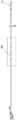
图2A是示意性示出根据本申请的实施例的超声刀的波导杆和作用部的图示;2A is a diagram schematically illustrating a waveguide rod and an action portion of an ultrasonic knife according to an embodiment of the present application;
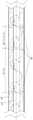
图2B是图2A中的虚线框所示的波导杆的局部的放大截面示意图;FIG. 2B is an enlarged cross-sectional schematic diagram of a part of the waveguide rod shown in the dotted frame in FIG. 2A;
图3是示意性示出根据本申请的实施例的超声刀的频率区间和谐振频率的图示;3 is a diagram schematically illustrating frequency intervals and resonant frequencies of an ultrasonic blade according to an embodiment of the present application;
图4A-图4B是示意性示出根据本申请的实施例的超声刀的工作频率随时间变化的图示;4A-4B are diagrams schematically illustrating the variation of the operating frequency of the ultrasonic blade with time according to an embodiment of the present application;
图5是示出根据本申请的实施例的超声刀的操作的流程图。FIG. 5 is a flowchart illustrating the operation of the ultrasonic blade according to an embodiment of the present application.
具体实施方式Detailed ways
以下参考附图描述根据本申请的实施例的超声刀的结构及其操作。图1示出了根据本申请的实施例的超声刀的各组件建构的示意图。如图1所示,在一些实施例中,超声外科系统包含主机10、换能器20、手柄30、轴组件40、作用部50、脚踏开关60。轴组件40包括波导杆和套管,如后文参考图2A和图2B更详细描述的。在一些实施例中,套管可以包括外套管和内套管(未示出),用于超声刀的远端执行部的闭合和张开。The structure and operation of the ultrasonic blade according to the embodiments of the present application will be described below with reference to the accompanying drawings. FIG. 1 shows a schematic diagram of the construction of various components of an ultrasonic blade according to an embodiment of the present application. As shown in FIG. 1 , in some embodiments, the ultrasonic surgical system includes a
主机10提供电信号以驱动换能器20产生相应的超声振动。在一些实施例中,主机10包含电源转换器、时钟、处理器、放大电路等,以生成用于驱动换能器20所需的电信号,例如与所需频率相对应的方波电信号、正弦电信号等。换能器20包含响应于电信号而产生相应频率的超声机械振动的振动元件,例如压电元件。在一些实施例中,振动元件的振动频率可以实质上对应于来自主机10的电信号的频率。在此情况下,通过调节主机10输出的电信号的频率,可以改变换能器20所产生的超声振动的频率。如本文中所使用的,主机10输出的“电信号的频率”与由该电信号驱动的换能器20所产生的“超声振动的频率”可互换地使用,因为两者在常规操作的情况下实质上对应。在一些实施例中,轴组件40的波导杆一端连接换能器20(在手柄30的外壳之内),而轴组件40的波导杆的另一端是作用部50,作用部50接触组织以进行切割等操作。这样轴组件40将换能器20所产生的超声振动传导到作用部50。The
大功率的超声振动能够使与作用部50接触的组织细胞在瞬间水分气化、蛋白质氢键断裂、细胞崩解,从而切开组织。传统地,由大功率的超声机械振动引起的摩擦热可以辅助在切开组织的同时进行凝固止血。作为示例,目前使用稳定性较好的超声切割的55.5kHz的中心频率。The high-power ultrasonic vibration can instantly vaporize the tissue cells in contact with the
然而,55.5kHz的频率虽然具有良好的切割效果,但缺少对切口的杀菌作用。因此,在使用超声刀进行的例如腹腔镜手术之后,往往需要给予较大剂量的抗生素以防感染。研究表明,除上述切割作用之外,超声振动还可以引发液体的空化作用。具体地,在超声振动的作用下,液体中的微小气泡核产生振动。当声压达到一定强度时,气泡将迅速膨胀,然后突然闭合,并在气泡闭合时产生冲击波。空化作用中的气泡的寿命约0.1μs,在急剧崩溃时可释放出巨大的能量,并产生速度约为110m/s的具有强大冲击力的微射流,并同时产生局部高温高压(5000K、1800大气压)。空化作用所产生的上述瞬时高温高压可用于手术组织附近的局部杀菌。However, although the frequency of 55.5kHz has a good cutting effect, it lacks the bactericidal effect on the cut. Therefore, higher doses of antibiotics are often given to prevent infection after, for example, laparoscopic surgery using the ultrasonic knife. Studies have shown that, in addition to the above-mentioned cutting action, ultrasonic vibration can also induce cavitation in liquids. Specifically, under the action of ultrasonic vibration, tiny bubble nuclei in the liquid vibrate. When the sound pressure reaches a certain intensity, the bubble will expand rapidly and then suddenly close, and a shock wave will be generated when the bubble closes. The lifespan of the bubbles in cavitation is about 0.1μs, which can release huge energy when it collapses sharply, and generate a micro-jet with a strong impact force with a speed of about 110m/s, and at the same time generate local high temperature and high pressure (5000K, 1800 atmospheric pressure). The above-mentioned transient high temperature and high pressure generated by cavitation can be used for local sterilization near the surgical tissue.
空化作用的效果受到功率、频率、液体的物理性质(例如,表面张力、粘度、温度、含气量等)等因素影响。特别地,超声振动的频率越高,产生空化作用所需的功率也越强。换言之,在医用手术超声刀的合理功率范围内,较低的频率将有利于产生较显著的空化作用,从而提高灭菌的效果。研究表明,20kHz至38kHz范围内的超声振动的杀菌效果好。然而,切割常用的55.5kHz的中心频率在该范围之外,因此仅能产生较弱的空化作用。The effect of cavitation is affected by factors such as power, frequency, and physical properties of the liquid (eg, surface tension, viscosity, temperature, air content, etc.). In particular, the higher the frequency of ultrasonic vibration, the stronger the power required to generate cavitation. In other words, within the reasonable power range of the medical surgical ultrasonic knife, a lower frequency will help to generate more significant cavitation, thereby improving the effect of sterilization. Studies have shown that ultrasonic vibration in the range of 20kHz to 38kHz has a good sterilization effect. However, the center frequency of 55.5 kHz, which is commonly used for cutting, is outside this range and thus only produces weak cavitation.
基于这个发现,本申请提出了一种超声刀,其能够周期性交替地或以其他方式变化地输出55.5kHz的超声振动和20kHz至38kHz范围内的超声振动,从而以高频率的超声振动进行切割组织的同时,可以利用低频率的较强的空化作用对组织附近进行局部杀菌,以减少术后抗生素的需求量并改善预后。Based on this finding, the present application proposes an ultrasonic blade that can periodically alternately or otherwise vary outputting ultrasonic vibrations of 55.5 kHz and ultrasonic vibrations in the range of 20 kHz to 38 kHz to perform cutting with high-frequency ultrasonic vibrations At the same time, low-frequency strong cavitation can be used for local sterilization near the tissue to reduce the need for postoperative antibiotics and improve the prognosis.
为了将换能器20所产生的超声振动高效地传导到作用部50,轴组件40(特别地,轴组件40的波导杆42,如以下参考图2A和图2B将更详细描述的)需要在该超声振动的频率f下发生谐振。根据机械振动的传播原理,在轴组件40(特别地,波导杆42)的有效传播长度等于超声振动在该频率f下的波长λ=v/f(v表示机械波在轴组件40中的传播速度)的一半的整数倍nλ/2(n为正整数)的情况下,可以实现超声振动的高效传导。可以理解,超声刀的轴组件40(特别地,波导杆42)应具有合理的长度,以便在足以使作用部50触及需要操作的组织的情况下避免因长度过长而造成操作难度的不必要增大。在一些实施例中,波导杆42的长度可以为十几厘米、二十几厘米或三十几厘米等,取决于需要操作的组织的深度,并满足上述nλ/2的长度要求。In order to efficiently conduct the ultrasonic vibration generated by the
进一步地,在一些实施例中,为了能够对于55.5kHz的第一频率f1的超声振动和20kHz至38kHz范围内的第二频率f2的超声振动同时实现高效的传导,可以将该第二频率f2选择为55.5kHz的二分之一,即27.75kHz。在此情况下,27.75kHz的第二频率f2所对应的第二波长λ2是55.5kHz的第一频率f1所对应的第一波长λ1的2倍。因此,可以理解,当波导杆42的长度为第二波长λ2的一半的整数倍nλ2/2时,该长度也为第一波长λ1的相应整数倍nλ2/2=2nλ1/2=nλ1。因此,通过至少部分地基于第二频率f2(例如,27.75kHz)来确定波导杆42的长度和支撑部的设置位置,可以兼顾对于55.5kHz的第一频率λ1和27.75kHz的第二频率λ2的超声振动的高效传导,如后文将参考图2B更详细描述的。Further, in some embodiments, in order to be able to simultaneously achieve efficient conduction for the ultrasonic vibration of the first frequency f1 of 55.5 kHz and the ultrasonic vibration of the second frequency f2 in the range of 20 kHz to 38 kHz, the second frequency may be f2 was chosen to be one- half of 55.5kHz, which is 27.75kHz. In this case, the second wavelength λ2 corresponding to the second frequency f2 of 27.75 kHz is twice the first wavelength λ1 corresponding to the first frequency f1 of 55.5 kHz. Therefore, it can be understood that when the length of the
图2A是示意性示出根据本申请的实施例的超声刀的波导杆42和作用部50的图示。图2A所示的长度、直径等仅为示意性目的,且并未按比例绘制,因此不对根据本申请的波导杆42构成任何限制。图2B是图2A中的虚线框所示的波导杆42的局部的放大截面示意图。如图2B所示,轴组件40由内部的波导杆42、套设在波导杆42的周围的套管44以及沿着波导杆42的长度方向间隔地套设的支撑部46构成。支撑部46将波导杆42柔性地支撑到机械强度较高的套管44的内壁,从而提高轴组件40的机械稳定性,并提高超声振动在作用部50处的输出强度。FIG. 2A is a diagram schematically illustrating the
在不被任何理论限制的情况下,支撑部46可以沿着波导杆42的长度方向设置在超声振动沿着波导杆42传播所形成的波节位置处,即沿着波导杆42的长度方向上振动幅度最小的位置处。在此情况下,支撑部46能够在提供支撑的情况下尽可能避免吸收振动能量,从而在换能器20的输出功率固定的情况下提高作用部50输出的超声振动的功率。此外,通过吸收除谐振频率之外的其他频率的振动,支撑部46还能够在一定程度上限制其他频率的振动的传播,从而使输出的超声振动的频率更为集中。Without being bound by any theory, the
在同时使用55.5kHz的第一频率和27.75kHz的第二频率的情况下,支撑部46的设置位置需要兼顾两个频率下的波节位置。由于第二频率f2对应的第二波长λ2是第一频率f1对应的第一波长λ1的二倍,因此第一频率f1在轴组件40的波导杆42中传播所形成的波节n1数目是第二频率f2在轴组件40的波导杆42中传播所形成的波节n2的数目的二倍。换言之,如图2B所示,第一频率f1的每对相邻波节n1中的一者与第二频率f2的波节n2重合,而另一者与第二频率f2的波节n2不重合。又换言之,第二频率f2的波节n2全部与第一频率f1的波节n1重合。如图2B所示,在一些实施例中,将支撑部46沿着波导杆42的长度方向的位置设置为对应于波导杆42在第二频率f2下所产生的波节位置n2中的至少一些波节位置处。在此情况下,可以使全部支撑部46吸收尽可能少的超声振动能量,从而提高输出到作用部50的超声振动的功率。此外,通过吸收除第一频率f1和第二频率f2之外的其他频率的振动,支撑部46还可以在一定程度上限制其他频率的振动的传播,从而使输出的超声振动的频率更为集中。When using the first frequency of 55.5 kHz and the second frequency of 27.75 kHz at the same time, the installation position of the
在一些实施例中,如图2B所示,可以不在全部波节位置n2处设置支撑部46,而是仅在波节位置n2中的一些位置处设置支撑部46。相应地,相邻两个支撑部46之间的距离可以为第二频率f2对应的波长的一半λ2/2的整数倍nλ2/2(n为正整数),例如d1=2×λ2/2=λ2,d2=λ2/2,等等。可以理解,这些支撑部46之间的距离将为相应第一频率f1对应的波长λ1的整数倍nλ1。In some embodiments, as shown in FIG. 2B, supports 46 may not be provided at all node positions n2 , but only at some of node positions n2 . Correspondingly, the distance between two
应理解,虽然以出于设备设计目的,将第一频率描述为55.5kHz,但实践中,所使用的第一频率可以基于波导杆42的实际谐振频率而在以55.5kHz为中心的可接受频率区间内选择。进而,所使用的第二频率可以通过将所选择的所使用的第一频率除以二得到。替代地,也可以先基于波导杆42的实际谐振频率而在以27.75kHz为中心的可接受频率区间内选择第二频率,然后通过将所选择的所使用的第二频率乘以二得到所使用的第一频率。具体地,虽然波导杆42设计为具有例如55.5kHz的谐振频率,但波导杆42的实际谐振频率受制造公差、材料不均匀性和温度导致的机械性能变化等因素影响,并且可能偏离所设计的55.5kHz。因此,如果直接将主机10所输出的电信号的频率选择为55.5kHz,则可能偏离波导杆42的实际谐振频率,从而造成超声振动的传导效率下降。It should be understood that while the first frequency is described as 55.5 kHz for device design purposes, in practice the first frequency used may be at an acceptable frequency centered at 55.5 kHz based on the actual resonant frequency of the
图3是示意性示出根据本申请的实施例的超声刀的可接受频率区间和谐振频率的图示,其中横坐标表示频率f/kHz,纵坐标表示超声能量的传导效率e%。传导效率e%表示由波导杆42输出到作用部50的功率与由换能器20所产生的超声振动的功率的比例百分数。如图3所示,超声能量的传导效率e%在谐振频率f2和f1=f2×2下较高,而在其他频率下较低。在一些实施例中,可以将55.5kHz作为可接受频率区间的中心,将可接受频率区间的宽度设置为2kHz(即,±1kHz),从而得到第一频率区间[f1-,f1+],即54.5kHz至56.5kHz。相应地,第二频率区间的上下限f2-、f2+可以分别为第一频率区间的上下限f1-、f1+的一半,例如f2-=27.25kHz至f2+=28.25kHz。在每次更换新的波导杆42时,或者主机10因其他原因没有储存已锁定的第一谐振频率f1的情况下,或者当医生或助手主动操作主机10以命令进行扫描时,主机10可以在第一频率区间[f1-,f1+]内扫描以确定超声振动传导效率e%最高的第一谐振频率f1以用于组织切割,并将该第一谐振频率f1除以二以得到第二谐振频率f2=f1/2以用于杀菌。替代地,主机10也可以在第二频率区间[f2-,f2+]内扫描以确定超声振动传导效率e%最高的第二谐振频率f2以用于杀菌,并将该第二谐振频率f2乘以二以得到第一谐振频率f1=f2×2以用于组织切割。应注意,以上可接受频率区间的中心和宽度仅为示例,并且可以根据实际需要灵活选择。3 is a diagram schematically illustrating acceptable frequency intervals and resonant frequencies of an ultrasonic blade according to an embodiment of the present application, wherein the abscissa represents the frequency f/kHz, and the ordinate represents the transmission efficiency e% of ultrasonic energy. The conduction efficiency e% represents the percentage of the ratio of the power output by the
在不受任何理论限制的情况下,扫描可接受频率区间以确定对应于最高超声振动传导效率e%的谐振频率可以通过本领域已知或未来待开发的任意方法进行。在一些实施例中,可以通过主机10检测并比较换能器20的供电端子上的电压和电流相位,并将对应于最小相位差的频率确定为该可接受频率区间内的谐振频率。Without being bound by any theory, scanning the acceptable frequency interval to determine the resonant frequency corresponding to the highest ultrasonic vibration conduction efficiency e% can be performed by any method known in the art or to be developed in the future. In some embodiments, the
主机10配置为,通过调节主机10的电信号的频率,以驱动换能器20。换能器20产生谐振信号,主机10检测谐振信号并在第二频率区间[f2-,f2+]内扫描,从而先锁定波导杆42处于第二谐振频率f2,然后将第一谐振频率f1锁定为第二谐振频率的两倍f1=f2×2。或者,通过调节主机10的电信号的频率,以驱动换能器20。换能器20产生谐振信号,主机10检测谐振信号并在第一频率区间[f1-,f1+]内扫描,从而先锁定波导杆42的第一谐振频率f1,然后将第二谐振频率f2锁定为第一谐振频率的一半f2=f1/2。The
图4A-图4B是示意性示出根据本申请的实施例的超声刀的工作频率随时间变化的图示,其中横坐标表示时间,纵坐标表示振动频率,t=0时间表示作用部50接触目标组织并且主机10开始输出电信号以驱动换能器20产生超声振动的时间,例如医生踩下开关60的时间。在一些实施例中,如图4A所示,振动频率在0时间至t1时间为第二谐振频率f2,例如约27.75kHz。然后,在t1时间之后,振动频率变为第一谐振频率f1,例如约55.5kHz。在此情况下,在对接触的目标组织用过第一谐振频率f1进行切割之前,可以先在0至t1时间内用较低的第二谐振频率f2所产生的空化作用对目标组织附近进行局部灭菌,从而降低了感染可能性。4A-4B are diagrams schematically illustrating the change of the working frequency of the ultrasonic blade with time according to an embodiment of the present application, wherein the abscissa represents the time, the ordinate represents the vibration frequency, and the time t=0 represents the contact of the
在一些实施例中,如图4B所示,从t=0时间开始,振动频率在第一时间周期T1内为第二谐振频率f2,例如约27.75kHz。然后,振动频率在时间t1变为第一谐振频率f1并持续第二时间周期T2,例如约55.5kHz。再之后,振动频率在时间t2变为第二谐振频率f2并持续第一时间周期T1,以此类推。在此情况下,振动频率在第二谐振频率f2与第一谐振频率f1之间周期性地交替变化,从而对随着组织切割而暴露出来的新创面进行不断的杀菌,以进一步降低感染的可能性。应理解,图4A和图4B所示的时间点和时间周期仅出于示例目的,而不表示实际的时间、持续时间或其比例。In some embodiments, as shown in FIG. 4B , starting from time t=0, the vibration frequency is the second resonant frequency f2 for the first time period T1 , eg, about 27.75 kHz. Then, the vibration frequency changes to the first resonant frequency f1 at time t1 for a second time period T2 , eg, about 55.5 kHz. After that, the vibration frequency changes to thesecond resonant frequency f2 at timet2 for thefirst time period T1, and so on. In this case, the vibration frequency alternates periodically between the second resonant frequency f2 and the first resonant frequency f1 , so as to continuously sterilize the new wound surface exposed as the tissue is cut to further reduce infection possibility. It should be understood that the time points and time periods shown in FIGS. 4A and 4B are for illustrative purposes only and do not represent actual times, durations, or proportions thereof.
图5是示出根据本申请的实施例的超声刀的操作的流程图。如上所述,超声刀需要锁定波导杆42的谐振频率以进行组织切割和灭菌操作。在超声刀的使用过程中,可能出现更换波导杆42的情景,例如,目标组织深度过深、波导杆42损坏或过热等。此时,将花费一定时间更换波导杆42,并且可能需要主机10在频率区间内进行重新扫描以锁定波导杆42的新的实际谐振频率。作为示例,可以在更换波导杆42之后,当医生踩下开关60时,主机10自动地重新扫描可接受频率区间,使得医生或助手无需在主机上操作按键或用户界面以命令主机10执行扫描。然而,由于间隔较长时间后也可能并未更换波导杆42(例如,进行了较复杂耗时的手术操作),因此期望不必在该次间隔之后执行重新扫描以节省操作时间。FIG. 5 is a flowchart illustrating the operation of the ultrasonic blade according to an embodiment of the present application. As mentioned above, the ultrasonic blade needs to lock the resonant frequency of the
为了兼顾医生或助手的操作便利和节省时间,本申请设想在波导杆42上设置识别标签(未示出,例如,RFID标签),并且在换能器20上设置传感器(未示出,例如,RFID传感器)。通过换能器20上的传感器对波导杆42上的识别标签进行识别,从而确定波导杆42是否已被更换。In order to take into account the operational convenience and time saving of the doctor or assistant, the present application envisages providing an identification tag (not shown, for example, an RFID tag) on the
具体地,当自从换能器20上次(例如,指代为第N-1次)响应于来自主机10的电信号而产生超声振动之后尚未经过阈值时间时,由于不太可能在这样很短的时间内更换波导杆42,因此在本次(例如,指代为第N次)操作中,换能器20不需进行识别操作,主机10也不需进行重新扫描(除非医生或助手主动操作主机10以命令进行扫描),而是直接使用之前锁定的第一谐振频率f1和第二谐振频率f2进行组织切割和灭菌操作。当自从换能器20上次响应于来自主机10的电信号而产生超声振动之后已经经过阈值时间时,传感器感测识别标签并与上次感测的识别标签进行比较。当所感测到识别标签与上次感测的识别标签相同时,表示并未更换波导杆42,因此换能器20不需进行操作,主机10也不需进行重新扫描(除非医生或助手主动操作主机10以命令进行扫描),而是直接使用之前锁定的第一谐振频率f1和第二谐振频率f2进行组织切割和灭菌操作,从而节省了操作时间。Specifically, when the threshold time has not elapsed since the last time (eg, referred to as the N-1 th time) the
相应地,当所感测到识别标签与上次感测的识别标签不同时,将波导杆42的识别标签的变化报告给主机10,以指示波导杆42已经被更换。响应于波导杆42的识别标签变化的报告,主机10可以通过调节电信号的频率以驱动换能器20在频率区间内重新进行扫描,以锁定新的第一谐振频率f1’和f2’。在一些实施例中,主机10可以在第二频率区间(例如,27.25kHz至28.25kHz)之间进行扫描,以确定波导杆42的新的第二谐振频率f2’。然后,将该第二谐振频率f2’乘以二以得到波导杆42的新的第一谐振频率f1’。替代地,在其他实施例中,主机也可以在第一频率区间(例如,54.5kHz至56.5kHz)之间进行扫描,以确定波导杆42的新的第一谐振频率f1’。然后,将该第一谐振频率f1’除以二以得到波导杆42的新的第二谐振频率f2’。Accordingly, when the sensed identification tag is different from the last sensed identification tag, the change in the identification tag of the
应理解,可以对所公开的装置进行各种修改。因此,以上描述不应理解为限制,而仅是本公开的方面的举例。本领域技术人员将设想到在本公开的范围和精神内的其他修改。例如,一个所描述的方面的任意和全部特征可以适当地整合到另一方面中,并且该特征在一个方面中的有益效果可以预期在另一方面中实现。It should be understood that various modifications may be made to the disclosed apparatus. Therefore, the above description should not be construed as limiting, but merely as exemplifications of aspects of the present disclosure. Those skilled in the art will envision other modifications within the scope and spirit of the present disclosure. For example, any and all features of one described aspect may be suitably integrated in another aspect, and the benefits of such a feature in one aspect may be expected to be realized in another.
Claims (10)
Priority Applications (1)
| Application Number | Priority Date | Filing Date | Title |
|---|---|---|---|
| CN202210718639.8ACN115054325B (en) | 2022-06-23 | 2022-06-23 | Ultrasonic surgical system |
Applications Claiming Priority (1)
| Application Number | Priority Date | Filing Date | Title |
|---|---|---|---|
| CN202210718639.8ACN115054325B (en) | 2022-06-23 | 2022-06-23 | Ultrasonic surgical system |
Publications (2)
| Publication Number | Publication Date |
|---|---|
| CN115054325Atrue CN115054325A (en) | 2022-09-16 |
| CN115054325B CN115054325B (en) | 2025-09-26 |
Family
ID=83202951
Family Applications (1)
| Application Number | Title | Priority Date | Filing Date |
|---|---|---|---|
| CN202210718639.8AActiveCN115054325B (en) | 2022-06-23 | 2022-06-23 | Ultrasonic surgical system |
Country Status (1)
| Country | Link |
|---|---|
| CN (1) | CN115054325B (en) |
Citations (5)
| Publication number | Priority date | Publication date | Assignee | Title |
|---|---|---|---|---|
| US20030093103A1 (en)* | 2001-08-08 | 2003-05-15 | Don Malackowski | Surgical tool system with components that perform inductive data transfer |
| CN101772325A (en)* | 2007-07-31 | 2010-07-07 | 伊西康内外科公司 | temperature controlled ultrasonic surgical instruments |
| CN103721308A (en)* | 2012-10-15 | 2014-04-16 | 北京速迈医疗科技有限公司 | Ultrasonic debridement surgery system with enhanced cavitation effect |
| US20170007852A1 (en)* | 2015-07-09 | 2017-01-12 | Misonix, Incorporated | Ultrasonic medical probe with failsafe for sterility and associated method |
| CN218419975U (en)* | 2022-06-23 | 2023-02-03 | 宁波海泰科迈医疗器械有限公司 | Ultrasonic surgical system |
- 2022
- 2022-06-23CNCN202210718639.8Apatent/CN115054325B/enactiveActive
Patent Citations (5)
| Publication number | Priority date | Publication date | Assignee | Title |
|---|---|---|---|---|
| US20030093103A1 (en)* | 2001-08-08 | 2003-05-15 | Don Malackowski | Surgical tool system with components that perform inductive data transfer |
| CN101772325A (en)* | 2007-07-31 | 2010-07-07 | 伊西康内外科公司 | temperature controlled ultrasonic surgical instruments |
| CN103721308A (en)* | 2012-10-15 | 2014-04-16 | 北京速迈医疗科技有限公司 | Ultrasonic debridement surgery system with enhanced cavitation effect |
| US20170007852A1 (en)* | 2015-07-09 | 2017-01-12 | Misonix, Incorporated | Ultrasonic medical probe with failsafe for sterility and associated method |
| CN218419975U (en)* | 2022-06-23 | 2023-02-03 | 宁波海泰科迈医疗器械有限公司 | Ultrasonic surgical system |
Also Published As
| Publication number | Publication date |
|---|---|
| CN115054325B (en) | 2025-09-26 |
Similar Documents
| Publication | Publication Date | Title |
|---|---|---|
| EP0765637B1 (en) | Ultrasonic instrument for surgical applications | |
| JP4070984B2 (en) | Method for detecting the presence of a blade in an ultrasonic surgical system | |
| US5669922A (en) | Ultrasonically driven blade with a radial hook that defines a circular recess | |
| US9622749B2 (en) | Ultrasonic generator systems and methods | |
| US6626926B2 (en) | Method for driving an ultrasonic system to improve acquisition of blade resonance frequency at startup | |
| JP4070985B2 (en) | How to detect loose blades in a handpiece connected to an ultrasonic surgical system | |
| JP4180264B2 (en) | A method for improving the starting performance of an ultrasound system under zero load conditions | |
| US20160128769A1 (en) | Surgical device for the removal of tissue employing a vibrating beam with cold plasma sterilization | |
| US20150257778A1 (en) | Surgical device employing a cantilevered beam dissector | |
| JP2005027907A (en) | Ultrasonic surgery system and probe | |
| KR20060105660A (en) | System for controlling ultrasonic clamping and cutting tools | |
| JPH07500273A (en) | electrosurgical device | |
| WO1997037598A1 (en) | Dual mode ultrasonic surgical apparatus | |
| JP2003153918A (en) | Method for determining temperature of transducer of ultrasonic hand piece | |
| CN117241746A (en) | Method for controlling a therapeutic ultrasound interventional system | |
| CN218419975U (en) | Ultrasonic surgical system | |
| CN115054325B (en) | Ultrasonic surgical system | |
| JP4059336B2 (en) | Blade breakage detection method | |
| JP2002058679A (en) | Ultrasonic treating instrument | |
| WO2019198217A1 (en) | Medical device system, abnormality determination method and abnormality determination program | |
| JP3774477B2 (en) | Surgical device | |
| JP2959779B2 (en) | Ultrasonic treatment equipment | |
| JPH11318920A (en) | Hand piece for ultrasonic treatment device for surgery | |
| HK1131535A1 (en) | Ultrasonic surgical tool | |
| HK1131535B (en) | Ultrasonic surgical tool |
Legal Events
| Date | Code | Title | Description |
|---|---|---|---|
| PB01 | Publication | ||
| PB01 | Publication | ||
| SE01 | Entry into force of request for substantive examination | ||
| SE01 | Entry into force of request for substantive examination | ||
| GR01 | Patent grant |