CN115052536B - Universal Drill Guide System - Google Patents
Universal Drill Guide SystemDownload PDFInfo
- Publication number
- CN115052536B CN115052536BCN202180012910.XACN202180012910ACN115052536BCN 115052536 BCN115052536 BCN 115052536BCN 202180012910 ACN202180012910 ACN 202180012910ACN 115052536 BCN115052536 BCN 115052536B
- Authority
- CN
- China
- Prior art keywords
- drill
- universal
- stop
- wire
- drill bit
- Prior art date
- Legal status (The legal status is an assumption and is not a legal conclusion. Google has not performed a legal analysis and makes no representation as to the accuracy of the status listed.)
- Active
Links
- 238000005553drillingMethods0.000claimsabstractdescription32
- 230000006835compressionEffects0.000claimsdescription15
- 238000007906compressionMethods0.000claimsdescription15
- 230000014759maintenance of locationEffects0.000description83
- 210000000988bone and boneAnatomy0.000description62
- 238000000034methodMethods0.000description20
- 238000006073displacement reactionMethods0.000description5
- 210000001519tissueAnatomy0.000description5
- 230000001054cortical effectEffects0.000description2
- 230000000994depressogenic effectEffects0.000description2
- 230000004927fusionEffects0.000description2
- 238000003780insertionMethods0.000description2
- 230000037431insertionEffects0.000description2
- 238000003825pressingMethods0.000description2
- 230000001012protectorEffects0.000description2
- 230000000007visual effectEffects0.000description2
- 230000001154acute effectEffects0.000description1
- 229910045601alloyInorganic materials0.000description1
- 239000000956alloySubstances0.000description1
- 238000004140cleaningMethods0.000description1
- 239000003086colorantSubstances0.000description1
- 230000007797corrosionEffects0.000description1
- 238000005260corrosionMethods0.000description1
- 238000005520cutting processMethods0.000description1
- 230000000881depressing effectEffects0.000description1
- 230000000694effectsEffects0.000description1
- 230000003100immobilizing effectEffects0.000description1
- 239000007943implantSubstances0.000description1
- 239000003550markerSubstances0.000description1
- 239000000463materialSubstances0.000description1
- 238000005259measurementMethods0.000description1
- 230000000284resting effectEffects0.000description1
- 238000004904shorteningMethods0.000description1
- 229910001256stainless steel alloyInorganic materials0.000description1
- 230000001954sterilising effectEffects0.000description1
- 238000004659sterilization and disinfectionMethods0.000description1
- 238000001356surgical procedureMethods0.000description1
Images


Classifications
- A—HUMAN NECESSITIES
- A61—MEDICAL OR VETERINARY SCIENCE; HYGIENE
- A61B—DIAGNOSIS; SURGERY; IDENTIFICATION
- A61B17/00—Surgical instruments, devices or methods
- A61B17/16—Instruments for performing osteoclasis; Drills or chisels for bones; Trepans
- A61B17/1662—Instruments for performing osteoclasis; Drills or chisels for bones; Trepans for particular parts of the body
- A61B17/1671—Instruments for performing osteoclasis; Drills or chisels for bones; Trepans for particular parts of the body for the spine
- A—HUMAN NECESSITIES
- A61—MEDICAL OR VETERINARY SCIENCE; HYGIENE
- A61B—DIAGNOSIS; SURGERY; IDENTIFICATION
- A61B90/00—Instruments, implements or accessories specially adapted for surgery or diagnosis and not covered by any of the groups A61B1/00 - A61B50/00, e.g. for luxation treatment or for protecting wound edges
- A61B90/03—Automatic limiting or abutting means, e.g. for safety
- A—HUMAN NECESSITIES
- A61—MEDICAL OR VETERINARY SCIENCE; HYGIENE
- A61B—DIAGNOSIS; SURGERY; IDENTIFICATION
- A61B17/00—Surgical instruments, devices or methods
- A61B17/16—Instruments for performing osteoclasis; Drills or chisels for bones; Trepans
- A61B17/1613—Component parts
- A61B17/1615—Drill bits, i.e. rotating tools extending from a handpiece to contact the worked material
- A61B17/1617—Drill bits, i.e. rotating tools extending from a handpiece to contact the worked material with mobile or detachable parts
- A—HUMAN NECESSITIES
- A61—MEDICAL OR VETERINARY SCIENCE; HYGIENE
- A61B—DIAGNOSIS; SURGERY; IDENTIFICATION
- A61B17/00—Surgical instruments, devices or methods
- A61B17/16—Instruments for performing osteoclasis; Drills or chisels for bones; Trepans
- A61B17/1613—Component parts
- A61B17/1633—Sleeves, i.e. non-rotating parts surrounding the bit shaft, e.g. the sleeve forming a single unit with the bit shaft
- A—HUMAN NECESSITIES
- A61—MEDICAL OR VETERINARY SCIENCE; HYGIENE
- A61B—DIAGNOSIS; SURGERY; IDENTIFICATION
- A61B17/00—Surgical instruments, devices or methods
- A61B17/16—Instruments for performing osteoclasis; Drills or chisels for bones; Trepans
- A61B17/1637—Hollow drills or saws producing a curved cut, e.g. cylindrical
- A—HUMAN NECESSITIES
- A61—MEDICAL OR VETERINARY SCIENCE; HYGIENE
- A61B—DIAGNOSIS; SURGERY; IDENTIFICATION
- A61B17/00—Surgical instruments, devices or methods
- A61B17/16—Instruments for performing osteoclasis; Drills or chisels for bones; Trepans
- A61B17/1697—Instruments for performing osteoclasis; Drills or chisels for bones; Trepans specially adapted for wire insertion
- A—HUMAN NECESSITIES
- A61—MEDICAL OR VETERINARY SCIENCE; HYGIENE
- A61B—DIAGNOSIS; SURGERY; IDENTIFICATION
- A61B17/00—Surgical instruments, devices or methods
- A61B17/16—Instruments for performing osteoclasis; Drills or chisels for bones; Trepans
- A61B17/17—Guides or aligning means for drills, mills, pins or wires
- A61B17/1739—Guides or aligning means for drills, mills, pins or wires specially adapted for particular parts of the body
- A61B17/1757—Guides or aligning means for drills, mills, pins or wires specially adapted for particular parts of the body for the spine
- A—HUMAN NECESSITIES
- A61—MEDICAL OR VETERINARY SCIENCE; HYGIENE
- A61B—DIAGNOSIS; SURGERY; IDENTIFICATION
- A61B17/00—Surgical instruments, devices or methods
- A61B17/16—Instruments for performing osteoclasis; Drills or chisels for bones; Trepans
- A61B17/17—Guides or aligning means for drills, mills, pins or wires
- A61B17/1796—Guides or aligning means for drills, mills, pins or wires for holes for sutures or flexible wires
- A—HUMAN NECESSITIES
- A61—MEDICAL OR VETERINARY SCIENCE; HYGIENE
- A61B—DIAGNOSIS; SURGERY; IDENTIFICATION
- A61B17/00—Surgical instruments, devices or methods
- A61B17/56—Surgical instruments or methods for treatment of bones or joints; Devices specially adapted therefor
- A61B17/58—Surgical instruments or methods for treatment of bones or joints; Devices specially adapted therefor for osteosynthesis, e.g. bone plates, screws or setting implements
- A61B17/68—Internal fixation devices, including fasteners and spinal fixators, even if a part thereof projects from the skin
- A61B17/70—Spinal positioners or stabilisers, e.g. stabilisers comprising fluid filler in an implant
- A61B17/7074—Tools specially adapted for spinal fixation operations other than for bone removal or filler handling
- A61B17/7076—Tools specially adapted for spinal fixation operations other than for bone removal or filler handling for driving, positioning or assembling spinal clamps or bone anchors specially adapted for spinal fixation
- A61B17/7082—Tools specially adapted for spinal fixation operations other than for bone removal or filler handling for driving, positioning or assembling spinal clamps or bone anchors specially adapted for spinal fixation for driving, i.e. rotating, screws or screw parts specially adapted for spinal fixation, e.g. for driving polyaxial or tulip-headed screws
- A—HUMAN NECESSITIES
- A61—MEDICAL OR VETERINARY SCIENCE; HYGIENE
- A61B—DIAGNOSIS; SURGERY; IDENTIFICATION
- A61B17/00—Surgical instruments, devices or methods
- A61B17/56—Surgical instruments or methods for treatment of bones or joints; Devices specially adapted therefor
- A61B17/58—Surgical instruments or methods for treatment of bones or joints; Devices specially adapted therefor for osteosynthesis, e.g. bone plates, screws or setting implements
- A61B17/68—Internal fixation devices, including fasteners and spinal fixators, even if a part thereof projects from the skin
- A61B17/70—Spinal positioners or stabilisers, e.g. stabilisers comprising fluid filler in an implant
- A61B17/7074—Tools specially adapted for spinal fixation operations other than for bone removal or filler handling
- A61B17/7092—Tools specially adapted for spinal fixation operations other than for bone removal or filler handling for checking pedicle hole has correct depth or has an intact wall
- A—HUMAN NECESSITIES
- A61—MEDICAL OR VETERINARY SCIENCE; HYGIENE
- A61B—DIAGNOSIS; SURGERY; IDENTIFICATION
- A61B17/00—Surgical instruments, devices or methods
- A61B17/56—Surgical instruments or methods for treatment of bones or joints; Devices specially adapted therefor
- A61B17/58—Surgical instruments or methods for treatment of bones or joints; Devices specially adapted therefor for osteosynthesis, e.g. bone plates, screws or setting implements
- A61B17/68—Internal fixation devices, including fasteners and spinal fixators, even if a part thereof projects from the skin
- A61B17/84—Fasteners therefor or fasteners being internal fixation devices
- A61B17/846—Nails or pins, i.e. anchors without movable parts, holding by friction only, with or without structured surface
- A61B17/848—Kirschner wires, i.e. thin, long nails
- A—HUMAN NECESSITIES
- A61—MEDICAL OR VETERINARY SCIENCE; HYGIENE
- A61B—DIAGNOSIS; SURGERY; IDENTIFICATION
- A61B17/00—Surgical instruments, devices or methods
- A61B17/56—Surgical instruments or methods for treatment of bones or joints; Devices specially adapted therefor
- A61B17/58—Surgical instruments or methods for treatment of bones or joints; Devices specially adapted therefor for osteosynthesis, e.g. bone plates, screws or setting implements
- A61B17/88—Osteosynthesis instruments; Methods or means for implanting or extracting internal or external fixation devices
- A61B17/8897—Guide wires or guide pins
- A—HUMAN NECESSITIES
- A61—MEDICAL OR VETERINARY SCIENCE; HYGIENE
- A61B—DIAGNOSIS; SURGERY; IDENTIFICATION
- A61B17/00—Surgical instruments, devices or methods
- A61B17/56—Surgical instruments or methods for treatment of bones or joints; Devices specially adapted therefor
- A61B17/58—Surgical instruments or methods for treatment of bones or joints; Devices specially adapted therefor for osteosynthesis, e.g. bone plates, screws or setting implements
- A61B17/88—Osteosynthesis instruments; Methods or means for implanting or extracting internal or external fixation devices
- A61B17/92—Impactors or extractors, e.g. for removing intramedullary devices
- A—HUMAN NECESSITIES
- A61—MEDICAL OR VETERINARY SCIENCE; HYGIENE
- A61B—DIAGNOSIS; SURGERY; IDENTIFICATION
- A61B90/00—Instruments, implements or accessories specially adapted for surgery or diagnosis and not covered by any of the groups A61B1/00 - A61B50/00, e.g. for luxation treatment or for protecting wound edges
- A61B90/06—Measuring instruments not otherwise provided for
- A—HUMAN NECESSITIES
- A61—MEDICAL OR VETERINARY SCIENCE; HYGIENE
- A61B—DIAGNOSIS; SURGERY; IDENTIFICATION
- A61B90/00—Instruments, implements or accessories specially adapted for surgery or diagnosis and not covered by any of the groups A61B1/00 - A61B50/00, e.g. for luxation treatment or for protecting wound edges
- A61B90/03—Automatic limiting or abutting means, e.g. for safety
- A61B2090/033—Abutting means, stops, e.g. abutting on tissue or skin
- A61B2090/034—Abutting means, stops, e.g. abutting on tissue or skin abutting on parts of the device itself
- A—HUMAN NECESSITIES
- A61—MEDICAL OR VETERINARY SCIENCE; HYGIENE
- A61B—DIAGNOSIS; SURGERY; IDENTIFICATION
- A61B90/00—Instruments, implements or accessories specially adapted for surgery or diagnosis and not covered by any of the groups A61B1/00 - A61B50/00, e.g. for luxation treatment or for protecting wound edges
- A61B90/06—Measuring instruments not otherwise provided for
- A61B2090/062—Measuring instruments not otherwise provided for penetration depth
- A—HUMAN NECESSITIES
- A61—MEDICAL OR VETERINARY SCIENCE; HYGIENE
- A61B—DIAGNOSIS; SURGERY; IDENTIFICATION
- A61B90/00—Instruments, implements or accessories specially adapted for surgery or diagnosis and not covered by any of the groups A61B1/00 - A61B50/00, e.g. for luxation treatment or for protecting wound edges
- A61B90/08—Accessories or related features not otherwise provided for
- A61B2090/0801—Prevention of accidental cutting or pricking
- A61B2090/08021—Prevention of accidental cutting or pricking of the patient or his organs
Landscapes
- Health & Medical Sciences (AREA)
- Surgery (AREA)
- Life Sciences & Earth Sciences (AREA)
- Orthopedic Medicine & Surgery (AREA)
- Medical Informatics (AREA)
- General Health & Medical Sciences (AREA)
- Veterinary Medicine (AREA)
- Engineering & Computer Science (AREA)
- Biomedical Technology (AREA)
- Heart & Thoracic Surgery (AREA)
- Public Health (AREA)
- Molecular Biology (AREA)
- Animal Behavior & Ethology (AREA)
- Nuclear Medicine, Radiotherapy & Molecular Imaging (AREA)
- Oral & Maxillofacial Surgery (AREA)
- Dentistry (AREA)
- Neurology (AREA)
- Pathology (AREA)
- Surgical Instruments (AREA)
- Drilling And Boring (AREA)
- Earth Drilling (AREA)
- Holo Graphy (AREA)
Abstract
Translated fromChinese
Description
Translated fromChinese技术领域technical field
本公开总体上涉及一种用于脊柱固定的通用钻导系统。The present disclosure generally relates to a universal drill guide system for spinal fixation.
背景技术Background technique
脊柱融合术是一种将受损的椎骨移除,并将邻近被移除椎骨的椎骨与移植物融合在一起的手术。脊柱在融合期间中必须固定。为了固定脊柱,一根或多根固定棒被锚定到椎骨以限制移动。Spinal fusion is a surgery in which damaged vertebrae are removed and the vertebrae adjacent to the removed vertebrae are fused together with a graft. The spine must be immobilized during fusion. To stabilize the spine, one or more rods are anchored to the vertebrae to limit movement.
固定棒是用打入椎骨中的骨螺钉锚定到椎骨的。在骨螺钉被打入椎骨体之前,借助通用钻导系统以微创方式在椎骨体中准备一个孔。在一个可能的手术中,钻管穿过小切口,并被导航到椎骨体上的一个期望的入口点。然后,皮层冲头推进穿过管,在骨的皮层上冲一个起始孔。然后将皮层冲头从管中移除,并且将钻头通过管推进到起始孔。一旦钻头与起始孔对准,手术钻就被供电以钻一个所需直径和深度的孔。钻完螺钉孔后,移除钻导,并且可将骨螺钉打入螺钉孔中。Rods are anchored to the vertebrae with bone screws driven into the vertebrae. Before the bone screw is driven into the vertebral body, a hole is prepared in the vertebral body in a minimally invasive manner with the aid of a universal drill guide system. In one possible procedure, a drill tube is passed through a small incision and navigated to a desired entry point on the vertebral body. A cortical punch is then advanced through the tube to punch an initial hole in the cortex of the bone. The cortex punch is then removed from the tube, and the drill is advanced through the tube to the starting hole. Once the drill bit is aligned with the starting hole, the surgical drill is powered to drill a hole of the desired diameter and depth. After the screw holes are drilled, the drill guide is removed and a bone screw can be driven into the screw hole.
钻打螺钉孔时,必须小心控制钻打深度,确保钻头不会过于深入椎骨体中。控制钻打深度的一个选择是在钻管上附接某种类型的钻止挡,以限制钻头尖端在患者体内延伸超过钻管末端的距离。但是,如果必须容纳多个不同尺寸的钻头和钻管,则此选项可能难以实施。When drilling screw holes, the drilling depth must be carefully controlled to ensure that the drill bit does not penetrate too deeply into the vertebral body. One option for controlling drilling depth is to attach some type of drill stop to the drill tube to limit the distance the drill tip extends beyond the end of the drill tube within the patient. However, this option can be difficult to implement if multiple different sized drill bits and drill pipes must be accommodated.
将钻头引导到适当的位置可能很困难。因此,一些钻头具有通道,允许钻头通过克氏(Kirschner)线或“K氏线”。K氏线可以在一个所需的位置附接到骨上,以精确地将钻头和其他器械导航到该位置。虽然K氏线对导航有帮助,但是当在它们周围使用其他器械时,它们带来了许多挑战。It can be difficult to guide the drill into the proper position. Accordingly, some drill bits have channels that allow the drill bit to pass through a Kirschner wire, or "K's wire." K-wires can be attached to the bone at a desired location to precisely navigate drills and other instruments to that location. While K's wires are helpful for navigation, they present many challenges when using other instruments around them.
在钻打完成之后,有时需要从操作侧移除钻导,同时将钻管和钻头留在适当位置。这可能是一个技术挑战,因为钻止挡与钻头接合,以限制钻头的近端移动。在常规解决方案中,钻止挡在单独的过程中从钻导上拆卸/释放,导致复杂的移除过程并因此增加了操作持续时间。After drilling is complete, it is sometimes necessary to remove the drill guide from the operator side while leaving the drill pipe and bit in place. This can be a technical challenge because the drill stop engages the drill bit to limit proximal movement of the drill bit. In conventional solutions, the drill stop is detached/released from the drill guide in a separate process, resulting in a complicated removal process and thus increasing the operation duration.
已知文献US 2014/7343553 A1为另外的现有技术。Document US 2014/7343553 A1 is known as further prior art.
发明内容Contents of the invention
与此相关,本公开是基于提供通用钻导系统的目的,在该通用钻导系统中,通用钻导的移除可以便于缩短操作持续时间。In this connection, the present disclosure is based on the object of providing a universal drill guide system in which removal of the universal drill guide may facilitate shortening the duration of the operation.
根据本公开,该目的的是通过一种通用钻导系统来实现,该系统包括通用钻导、可插入到通用钻导中的钻管和可插入到钻管中的钻头。通用钻导包括:钻止挡(止挡优选为支座形式),其被构造成邻接在钻头的止挡/支座表面上以限制钻头的钻打深度;锁定环,其可在锁定取向和释放取向之间旋转,在锁定取向中,插入到通用钻导中的钻管被锁定环锁定,在释放取向中,钻管可从锁定环释放;以及凸轮机构,其被构造成当锁定环旋转到释放取向时,将钻止挡枢转远离钻头的止挡表面。由此,当通用钻导的锁定环旋转到释放取向并且通用钻导在近端方向上从钻管和钻头释放时,钻止挡将自动地从钻头枢转。换句话说,当锁定环处于释放取向时,钻止挡在近端方向上对钻头的限制被自动取消。因此,避免了从钻头上释放钻止挡的附加过程,并且便于移除钻导。因此,缩短了操作持续时间。According to the present disclosure, this object is achieved by a universal drill guide system comprising a universal drill guide, a drill tube insertable into the universal drill guide and a drill bit insertable into the drill tube. A universal drill guide includes: a drill stop (preferably in the form of a standoff) configured to abut against the stop/seat surface of the drill bit to limit the drilling depth of the drill bit; rotation between a release orientation in which a drill pipe inserted into the universal drill guide is locked by a locking ring in which the drill pipe is releasable from the locking ring; and a cam mechanism configured to rotate the locking ring To the release orientation, the drill stop is pivoted away from the stop surface of the drill bit. Thus, when the locking ring of the universal drill guide is rotated to the release orientation and the universal drill guide is released from the drill tube and drill bit in the proximal direction, the drill stop will automatically pivot from the drill bit. In other words, when the locking ring is in the released orientation, the restriction of the drill bit by the drill stop in the proximal direction is automatically canceled. Thus, an additional process of releasing the drill stop from the drill bit is avoided and removal of the drill guide is facilitated. Therefore, the operation duration is shortened.
本公开的有利实施方案在下面更精确地解释。Advantageous embodiments of the present disclosure are explained more precisely below.
凸轮机构包括形成在锁定环上的凸轮槽以及形成在钻止挡的轴的远端上的凸轮跟随销。The cam mechanism includes a cam groove formed on the locking ring and a cam follower pin formed on the distal end of the shaft of the drill stop.
凸轮槽和凸轮跟随销被构造成使得锁定环顺时针旋转导致钻止挡同时逆时针旋转,使钻止挡枢转离开钻头的止挡表面。由此,可以容易地实现钻止挡和锁定环的同时旋转。可以方便通用钻导的释放过程。The cam slots and cam follower pins are configured such that clockwise rotation of the locking ring causes the drill stop to simultaneously rotate counterclockwise, pivoting the drill stop away from the stop surface of the drill bit. Thereby, simultaneous rotation of the drill stop and the locking ring can easily be achieved. Can facilitate the release process of the universal drill guide.
此外,压缩弹簧对锁定环施加偏置力,以将锁定环偏置在锁定取向上。Additionally, a compression spring applies a biasing force to the locking ring to bias the locking ring in the locked orientation.
优选地,开关可手动操作以对抗压缩弹簧的偏置力将锁定环从锁定取向旋转到释放取向。Preferably, the switch is manually operable to rotate the locking ring from the locked orientation to the released orientation against the biasing force of the compression spring.
钻止挡包括从钻止挡的轴横向延伸的止挡板。止挡板包括狭槽,该狭槽具有狭槽尺寸,该狭槽尺寸允许钻头的远端段穿过止挡板,直到钻头的止挡表面邻接在止挡板上。以此方式,就实现了钻打深度的限制。The drill stop includes a stop plate extending transversely from the shaft of the drill stop. The stop plate includes a slot having a slot size that allows the distal segment of the drill bit to pass through the stop plate until the stop surface of the drill bit abuts the stop plate. In this way, a limitation of the drilling depth is achieved.
通用钻导包括钻引导体。钻止挡的轴被构造成相对于引导体升高或降低,以设置期望的钻打深度。因此,可以很容易地选择不同的钻打深度。The Universal Drill Guide includes a drill guide body. The shaft of the drill stop is configured to be raised or lowered relative to the guide body to set the desired drilling depth. Therefore, different drilling depths can be easily selected.
此外,通用钻导包括锁,特别是弹簧加载锁,该锁被构造成与钻止挡的轴接合,以通过施加偏置力相对于引导体锁定轴。因此,钻止挡将相对于引导体保持在适当的位置,以限制所需的钻打深度。Furthermore, the universal drill guide includes a lock, in particular a spring-loaded lock, configured to engage the shaft of the drill stop to lock the shaft relative to the guide body by applying a biasing force. Thus, the drill stop will remain in place relative to the guide body to limit the desired drilling depth.
钻止挡的轴还包括与锁接合的圆周凹槽。The shaft of the drill stop also includes a circumferential groove that engages the lock.
此外,锁包括释放按钮,该释放按钮被构造成被向内按压以将锁从钻止挡的轴脱离。由此,可以通过相对于钻本体升高或降低钻止挡来选择钻头深度。在选择所需的钻深之后,释放按钮被释放,使得锁再次与钻止挡的轴接合,以将钻止挡保持在适当的位置。Additionally, the lock includes a release button configured to be pressed inwardly to disengage the lock from the shaft of the drill stop. Thereby, the drill depth can be selected by raising or lowering the drill stop relative to the drill body. After selecting the desired drilling depth, the release button is released so that the lock engages the shaft of the drill stop again to hold the drill stop in place.
优选地,通用钻导包括用于指示选定深度的第一组标记和第二组标记。Preferably, the universal drill guide includes a first set of markings and a second set of markings for indicating a selected depth.
更优选地,第一组标记包括在引导体上的垂直系列标记,并且第二组标记包括在钻止挡的轴上的垂直系列标记。因此,在通用钻导系统中,在通用钻导的两侧上设置两组标记。冗余标记在两个不同侧面上的这种构造解决了外科医生只能看到通用钻导一侧的情况。因此,可以提高可用性和人机工程学。More preferably, the first set of markings comprises a vertical series of markings on the guide body and the second set of markings comprises a vertical series of markings on the axis of the drill stop. Therefore, in the universal drill guide system, two sets of markings are provided on both sides of the universal drill guide. This configuration of redundant markings on two different sides solves the situation where the surgeon can only see one side of the common drill guide. Therefore, usability and ergonomics can be improved.
附图说明Description of drawings
结合附图中所示的非限制性示例,将更好地理解上述概述和以下详细描述,其中:The foregoing summary and the following detailed description will be better understood with reference to the non-limiting examples illustrated in the accompanying drawings, in which:
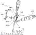
图1示出了根据本公开的一个方面的通用钻导系统的透视图;Figure 1 shows a perspective view of a universal drill guide system according to one aspect of the present disclosure;
图2示出了搭配图1的通用钻导系统使用的一组钻管的正视图;Figure 2 shows a front view of a set of drill pipes used with the universal drill guide system of Figure 1;
图3示出了搭配图1的通用钻导系统使用的一组钻头的正视图;Figure 3 shows a front view of a set of drill bits used with the universal drill guide system of Figure 1;
图4示出了图1的通用钻导系统的截断透视图;Figure 4 shows a fragmented perspective view of the universal drill guide system of Figure 1;
图5示出了图1的通用钻导系统的截断侧视图,示出了处于第一状态的弹簧加载锁;Figure 5 shows a fragmented side view of the universal drill guide system of Figure 1, showing the spring loaded lock in a first state;
图6示出了图1的通用钻导系统的截断侧视图,示出了处于第二状态的弹簧加载锁;Figure 6 illustrates a fragmented side view of the universal drill guide system of Figure 1, showing the spring loaded lock in a second state;
图7示出了图1的通用钻导系统的钻管夹持器的截断透视图,示出了处于第一位置的钻管夹持器;7 shows a fragmented perspective view of the drill pipe holder of the universal drill guide system of FIG. 1, showing the drill pipe holder in a first position;
图8示出了图1的通用钻导系统的钻管夹持器的截断透视图,示出了处于第二位置的钻管夹持器;Figure 8 shows a fragmented perspective view of the drill pipe holder of the universal drill guide system of Figure 1, showing the drill pipe holder in a second position;
图9A示出了在插入钻管的第一步骤期间图1的通用钻导系统的钻管夹持器的截断透视图;9A shows a fragmented perspective view of the drill pipe holder of the universal drill guide system of FIG. 1 during a first step of inserting the drill pipe;
图9B示出了在插入钻管的第二步骤期间图1的通用钻导系统的钻管夹持器的截断透视图;9B shows a fragmented perspective view of the drill pipe holder of the universal drill guide system of FIG. 1 during a second step of inserting the drill pipe;
图9C示出了在插入钻管的第三步骤期间图1的通用钻导系统的钻管夹持器的截断透视图;9C shows a fragmented perspective view of the drill pipe holder of the universal drill guide system of FIG. 1 during a third step of inserting the drill pipe;
图9D示出了在插入钻管的最后步骤之后,图1的通用钻导系统的钻管夹持器的截断透视图;Figure 9D shows a fragmented perspective view of the drill pipe holder of the universal drill guide system of Figure 1 after the final step of inserting the drill pipe;
图10示出了图1的通用钻导系统的钻管夹持器在锁定取向上的放大截断透视图;10 shows an enlarged fragmented perspective view of the drill pipe holder of the universal drill guide system of FIG. 1 in a locked orientation;
图11示出了图1所示的通用钻导系统的钻管夹持器在释放取向上的放大截断透视图;Figure 11 shows an enlarged fragmented perspective view of the drill pipe holder of the universal drill guide system shown in Figure 1 in a released orientation;
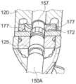
图12示出了图1的通用钻导系统的部件的放大透视图,示出了当钻止挡处于与钻头接合的位置时的部件;Figure 12 shows an enlarged perspective view of components of the universal drill guide system of Figure 1, showing the components when the drill stop is in the engaged position with the drill bit;
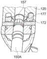
图13示出了图1的通用钻导系统的部件的放大透视图,示出了当钻止挡处于从钻头释放的位置时的部件;Figure 13 shows an enlarged perspective view of components of the universal drill guide system of Figure 1, showing the components when the drill stop is in a position released from the drill bit;
图14示出了图1的通用钻导系统的截断透视图,示出了处于要从钻管上拆下的状态的通用钻导系统;Figure 14 shows a fragmented perspective view of the universal drill guide system of Figure 1, showing the universal drill guide system in a state to be removed from the drill pipe;
图15示出了图1的通用钻导系统的另一截断透视图,示出了从钻管上拆下的通用钻导系统;Figure 15 shows another fragmented perspective view of the universal drill guide system of Figure 1, showing the universal drill guide system removed from the drill pipe;
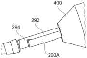
图16示出了根据本公开的另一方面的套管钻头和K氏线的透视图;16 shows a perspective view of a casing drill bit and K-wire according to another aspect of the present disclosure;
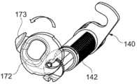
图17示出了根据本公开的另一方面的套管钻头、K氏线和K氏线固位机构的放大截断视图;17 illustrates an enlarged fragmented view of a casing bit, a K-wire, and a K-wire retention mechanism according to another aspect of the present disclosure;
图18示出了图17的套管钻头、K氏线和K氏线保持机构的放大截断横截面图;Figure 18 shows an enlarged fragmented cross-sectional view of the casing bit, K's wire, and K's wire retention mechanism of Figure 17;
图19示出了根据本公开的另一方面的K氏线的放大透视图,示出了K氏线的中段;19 illustrates an enlarged perspective view of a K-wire showing a mid-section of a K-wire according to another aspect of the present disclosure;
图20示出了根据本公开的另一方面的K氏线固位机构的放大透视图;20 shows an enlarged perspective view of a K-wire retention mechanism according to another aspect of the present disclosure;
图21示出了根据本公开的另一方面的套管钻头、K氏线和K氏线固位机构的截断透视图,其中力固位套筒示出在第一位置;21 illustrates a fragmented perspective view of a casing bit, a K-wire, and a K-wire retention mechanism, with the force retention sleeve shown in a first position, according to another aspect of the present disclosure;
图22示出了图21的套管钻头、K氏线和K氏线固位机构的截断透视图,其中力固位套筒示出在第二位置;22 illustrates a fragmented perspective view of the casing bit, K-wire, and K-wire retention mechanism of FIG. 21 with the force retention sleeve shown in a second position;
图23示出了根据本公开的另一个方面的套管钻头、K氏线和K氏线固位机构的放大截断透视图,其中套管钻头附接到钻驱动器;23 illustrates an enlarged fragmented perspective view of a casing bit, a K-wire, and a K-wire retention mechanism, with the casing bit attached to a drill driver, according to another aspect of the present disclosure;
图24示出了图23的套管钻头、K氏线和K氏线固位机构的另一个放大截断透视图,其中为了清楚起见,一些特征显示为透明的;Figure 24 shows another enlarged fragmentary perspective view of the casing bit, K-wire and K-wire retention mechanism of Figure 23, with some features shown transparent for clarity;
图25示出了根据本公开的另一个方面的钻移除工具的透视图;Figure 25 shows a perspective view of a drill removal tool according to another aspect of the present disclosure;
图26示出了图25的钻移除工具在附接到套管钻头和K氏线期间的截断透视图;Figure 26 shows a fragmented perspective view of the drill removal tool of Figure 25 during attachment to a casing bit and a K-wire;
图27示出了根据本公开的另一个方面的线夹的截断侧视图,示出处于未夹紧状态的线夹;Fig. 27 illustrates a fragmented side view of a wire clip according to another aspect of the present disclosure, showing the wire clip in an unclamped state;
图28示出了图27的线夹的截断侧视图,示出处于夹紧状态的线夹;Figure 28 shows a cutaway side view of the clamp of Figure 27, showing the clamp in a clamped state;
图29示出了图27的线夹的放大截断横截面图;Figure 29 shows an enlarged fragmentary cross-sectional view of the clip of Figure 27;
图30示出了图25的钻移除工具的部件的截断透视图;Figure 30 shows a fragmented perspective view of components of the drill removal tool of Figure 25;
图31示出了图25的钻移除工具的部件的另一截断透视图;Figure 31 shows another fragmented perspective view of components of the drill removal tool of Figure 25;
图32示出了图25的钻移除工具的另一截断透视图,示出了从患者身上移除钻头的过程;Figure 32 shows another fragmented perspective view of the drill removal tool of Figure 25, showing the process of removing the drill bit from the patient;
图33示出了根据本公开的另一方面的具有K氏线固位模块的骨螺钉驱动器的透视图,其中骨螺钉驱动器和K氏线固位模块穿过K氏线;33 illustrates a perspective view of a bone screw driver with a K-wire retention module according to another aspect of the present disclosure, wherein the bone screw driver and the K-wire retention module pass through the K-wire;
图34示出了图33的骨螺钉驱动器的远端的放大截断侧视图;Figure 34 shows an enlarged fragmentary side view of the distal end of the bone screw driver of Figure 33;
图35示出了图33的骨螺钉驱动器的远端的放大截断透视图;Figure 35 shows an enlarged fragmented perspective view of the distal end of the bone screw driver of Figure 33;
图36示出了具有图33所示的K氏线固位模块的骨螺钉驱动器在K氏线上推进期间的另一透视图;36 shows another perspective view of the bone screw driver with the K-wire retention module shown in FIG. 33 during advancement over a K-wire;
图37示出了具有图33的K氏线固位模块的骨螺钉驱动器的放大截断透视图,示出了K氏线固位模块的内部部件;Figure 37 shows an enlarged fragmentary perspective view of a bone screw driver having the K-wire retention module of Figure 33, showing the internal components of the K-wire retention module;
图38示出了图33的K氏线固位模块的侧视图,其中为了清楚起见,移除了一些部件,所示的K氏线固位模块处于第一操作模式;38 illustrates a side view of the K-wire retention module of FIG. 33 with parts removed for clarity, the K-wire retention module shown in a first mode of operation;
图39示出了图38的K氏线固位模块部件处于第一操作模式的放大截断透视图;39 illustrates an enlarged fragmented perspective view of the K-wire retention module component of FIG. 38 in a first mode of operation;
图40示出了图33的K氏线固位模块的侧视图,其中为了清楚起见,移除了一些部件,所示的K氏线固位模块处于第二操作模式;40 shows a side view of the K-wire retention module of FIG. 33 with parts removed for clarity, the K-wire retention module shown in a second mode of operation;
图41示出了图40的K氏线固位模块部件处于第二操作模式的放大截断透视图;Figure 41 shows an enlarged fragmented perspective view of the K-wire retention module component of Figure 40 in a second mode of operation;
图42示出了根据本公开的另一个方面的具有K氏线固位模块的替代骨螺钉驱动器的透视图,其中骨螺钉驱动器和K氏线固位模块穿过K氏线;42 illustrates a perspective view of an alternative bone screw driver with a K-wire retention module with the bone screw driver and K-wire retention module passing through the K-wire according to another aspect of the present disclosure;
图43示出了具有图42的K氏线固位模块的骨螺钉驱动器的透视图,示出了在第一操作模式下的K氏线固位模块的内部部件;43 shows a perspective view of a bone screw driver with the K-wire retention module of FIG. 42 showing the internal components of the K-wire retention module in a first mode of operation;
图44示出了图43的K氏线固位模块的内部部件在第一操作模式下的放大透视图;Figure 44 shows an enlarged perspective view of the internal components of the K-wire retention module of Figure 43 in a first mode of operation;
图45示出了图43的K氏线固位模块的内部部件在第二操作模式下的放大透视图;Figure 45 shows an enlarged perspective view of the internal components of the K-wire retention module of Figure 43 in a second mode of operation;
图46示出了图25的钻移除工具的放大截断透视图,示出了使用钻移除工具的替代技术的一个步骤;Figure 46 shows an enlarged fragmentary perspective view of the drill removal tool of Figure 25, illustrating a step in an alternative technique using the drill removal tool;
图47示出了图25的钻移除工具的另一放大截断透视图,示出了替代技术的另一步骤;Figure 47 shows another enlarged fragmentary perspective view of the drill removal tool of Figure 25, showing another step of the alternative technique;
图48示出了图25的钻移除工具的另一截断透视图,示出了替代技术的另一步骤;Figure 48 shows another fragmented perspective view of the drill removal tool of Figure 25, showing another step of the alternative technique;
图49示出了图25的钻移除工具的另一截断透视图,示出了替代技术的另一步骤;Figure 49 shows another fragmented perspective view of the drill removal tool of Figure 25, showing another step of the alternative technique;
图50示出了图25的钻移除工具的另一放大截断侧视图,示出了替代技术的另一步骤;Figure 50 shows another enlarged fragmentary side view of the drill removal tool of Figure 25, showing another step of the alternative technique;
图51示出了图25的钻移除工具的另一放大截断侧视图,示出了替代技术的另一步骤;Figure 51 shows another enlarged fragmentary side view of the drill removal tool of Figure 25, showing another step of the alternative technique;
图52示出了图25的钻移除工具的另一截断透视图,示出了替代技术的另一步骤;和Figure 52 shows another fragmented perspective view of the drill removal tool of Figure 25, showing another step in the alternative technique; and
图53示出了图25的钻移除工具的另一截断透视图,示出了替代技术的另一步骤。Fig. 53 shows another fragmented perspective view of the drill removal tool of Fig. 25, showing another step of the alternative technique.
具体实施方式Detailed ways
以下部分描述了根据本公开的用于固定颈椎的不同器械。The following sections describe different instruments for immobilizing the cervical spine according to the present disclosure.
在本公开中,“远端”基本上是指“在远离用户/外科医生朝向患者的方向上”,而“近端”基本上是指“在朝向用户/外科医生远离患者的方向上”。In this disclosure, "distal" basically means "in a direction away from the user/surgeon toward the patient", and "proximal" basically means "in a direction away from the user/surgeon away from the patient".
通用钻导系统Universal Drill Guide System
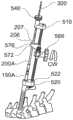
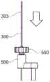
参考图1至图3,示出了根据一个示例的通用钻导系统100。通用钻导系统100具有通用钻导110。通用钻导110包括管状引导体120和从引导体120倾斜延伸的手柄130。如将描述,引导体120具有近端122,该近端122限定用于接收钻头的近端开口123。如将描述,引导体120还具有远端124,该远端124限定用于接收钻管的远端开口125。此外,引导体120具有钻止挡140,该钻止挡140通过限制钻头通过引导体120推进的距离来限制钻打深度。可选的导航星单元50附接到图1中的通用钻导110,该导航星单元可以被校准并搭配常规导航系统使用。Referring to FIGS. 1-3 , a universal
通用钻导系统100还包括一组可互换钻管150和一组可互换钻头200。该组可互换钻管150包括第一钻管150A、第二钻管150B和第三钻管150C。该组可互换钻头200包括第一钻头200A、第二钻头200B和第三钻头200C。然而,钻管150的数量和钻头200的数量不限于三个。所有的钻管150A、150B和150C以及所有的钻头200A、200B和200C都可连接到通用钻导110。The universal
如将在本描述的下一节中解释,第一钻头200A、第二钻头200B和第三钻头200C是插管的,并且具有设计成固位K氏线的特征。第一钻头200A、第二钻头200B和第三钻头200C也具有不同的钻打直径。每个钻打直径被构造成将特定尺寸的螺钉孔钻打到椎骨体中。第一钻头200A、第二钻头200B和第三钻头200C各自具有用于附接到钻驱动器的近端202和具有切削边缘以钻打孔的相对远端204。第一钻头200A、第二钻头200B和第三钻头200C还具有与扩径段207相邻的缩径段205,形成突变。这种突变形成位于近端202和远端204之间的止挡表面206。止挡表面206与引导体120上的钻止挡140协作,以限制钻头在钻打期间可进入椎骨体的距离。止挡表面206还起到在钻打操作之后移除钻头200A、200B和200C的作用,这将在另一节中说明。As will be explained in the next section of this description, the
第一钻管150A、第二钻管150B和第三钻管150C被设计成在钻打期间分别引导第一钻头200A、第二钻头200B和第三钻头200C的推进。第一钻管150A、第二钻管150B和第三钻管150C也在钻打期间保持第一钻头200A、第二钻头200B和第三钻头200C的轴向稳定。第一钻管150A、第二钻管150B和第三钻管150C中的每一个钻管具有用于附接到引导体120的近端152以及在钻打位置处插入患者中的相对的远端154。如将更详细地描述,钻管150A、150B和150C中的每一个钻管的近端152包括凹口157,该凹口便于附接到引导体120。The
第一钻管150A、第二钻管150B和第三钻管150C限定了钻头通道156,该钻头通道156具有特定尺寸的内径,以分别容纳第一钻头200A、第二钻头200B和第三钻头200C。因此,第一钻头200A、第二钻头200B和第三钻头200C分别被设计成仅与第一钻管150A、第二钻管150B和第三钻管150C一起工作。在第一钻管150A、第二钻管150B和第三钻管150C中的每一个钻管以及第一钻头200A、第二钻头200B和第三钻头200C中的每一个钻头上设置有标记,以帮助用户为所选择的钻头选择合适的钻管。任何类型的标记都可以使用。在系统100中,第一钻管150A和第一钻头200A具有匹配标记160A,第二钻管150B和第二钻头200B具有匹配标记160B,第三钻管150C和第三钻头200C具有匹配标记160C。标记160A、160B和160C是唯一的并且彼此不同,并且在每个钻管和钻头的圆周上以不同颜色带的形式出现。The
参考图4,钻止挡140具有轴142和从轴142横向延伸的止挡板144。止挡板144具有狭槽146,狭槽尺寸足够宽以允许第一钻头200A、第二钻头200B和第三钻头200C的远端段行经止挡板144。狭槽146小于第一钻头200A、第二钻头200B和第三钻头200C的止挡表面206的横截面尺寸。在这种布置中,止挡板144被构造成允许第一钻头200A、第二钻头200B和第三钻头200C中的每一个钻头通过止挡板144向前推进,直到它们各自的止挡表面206邻接在止挡板144上。此时,钻头已经达到选定的钻深,并且防止钻头进一步通过引导体120推进。Referring to FIG. 4 , the
参考图5和图6,钻止挡140可以升高或降低以设置期望的钻打深度设置。弹簧加载锁126可释放地与钻止挡140的轴142接合,以锁定和解锁轴142。轴142在一侧中具有一系列圆周凹槽143。弹簧加载锁126被构造成与凹槽143之一接合,以在弹簧偏置下锁定轴142的位置。弹簧加载锁126包括释放按钮127,如图5所示,释放按钮127可以向内按压。向内按压释放按钮127使弹簧加载锁126与轴142脱离,因此轴142可以相对于引导体120升高或降低以设置深度设置。一旦设置了深度设置,释放按钮127如图6所示被释放,以允许弹簧加载锁126在弹簧偏置下与轴142接合。弹簧加载锁126与轴142的接合会锁定轴142相对于引导体120的垂直位置并固定深度设置。Referring to Figures 5 and 6, the
通用钻导110包括外部上的两组标记,它们向用户提供所选深度设置的可视指示符。第一组标记128包括在引导体120的侧面上的垂直系列标记128a。第二组标记148包括轴142上的垂直系列标记148a。标记128a、148a中的每一个标记用对应于以毫米或其他测量单位为单位的深度的唯一数字标记。标记128a与标记148a被取向在通用钻导110的不同侧上。冗余标记在两个不同侧面上的这种放置解决了外科医生只能看到通用钻导110的一侧的情况。
引导体120包括自动钻管夹持器170,该自动钻管夹持器允许第一钻管150A、第二钻管150B和第三钻管150C中的每一个钻管以快速连接联接/快速配合连接连接到远端开口125。自动钻管夹持器170允许用户将钻管150A、150B和150C中的一个钻管插入引导体120中并将其锁定在适当位置,而不接触引导体120上的任何锁定机构。钻管被简单地插入到远端开口125中,直到它与自动锁接合。如上所述,钻管150A、150B和150C中的每一个钻管具有不同的内径以容纳钻头中的一个。然而,所有钻管150A、150B和150C具有与钻止挡140和自动钻管夹持器170接合的相同的外部尺寸。因此,所有钻管150A、150B和150C以相同的方式与自动钻管夹持器170相互作用。The
参考图7和图8,自动钻管夹持器170包括在引导体120内的弹簧加载锁定环172。锁定环172被构造成卡入形成在钻管150A、150B和150C中的每一个中的凹口157中。锁定环172在引导体120中可在锁定取向和释放取向之间旋转。一对压缩弹簧174在锁定环172上施加逆时针偏置力,以将锁定环172偏置在锁定取向上。每个压缩弹簧174支承靠着在锁定环172的其余部分在近端方向上或向上延伸的锁定凸片176上。Referring to FIGS. 7 and 8 , the automatic
锁定凸片176和压缩弹簧174被夹持在一对狭槽178中。每个压缩弹簧174的一端支承靠在狭槽178的端壁179上,并且弹簧174的相对端支承靠在锁定凸片176上。在这种布置中,锁定环172维持在锁定取向上,除非用户将锁定环172手动旋转到释放取向。锁定环172可以通过在附接到锁定环的开关173上施加顺时针方向的力来旋转。开关173延伸通过引导体120中的细长孔121,并暴露在引导体120的外部上。Locking
当锁定环172处于锁定取向时,如图7所示,压缩弹簧174释放能量以在它们各自的狭槽178中以逆时针方向推动锁定凸片176,以逆时针方向旋转锁定环172。当锁定环172处于释放取向时,如图8所示,锁定凸片176沿顺时针方向旋转,以在储存的能量下压缩它们各自的狭槽178中的压缩弹簧174。用户可以通过在顺时针方向上手动旋转开关173来将锁定环172从锁定取向移动到释放取向。When the
图9A至图9D示出了在其中将钻管(在此示例中为第一钻管150A)插入引导体120中并通过锁定环172锁定在适当位置的顺序。当第二钻管150B和第三钻管150C插入引导体120中时,发生相同的顺序。FIGS. 9A-9D show the sequence in which a drill pipe (in this example the
如图9A所示,钻管150A通过远端开口125插入到形成在引导体120中的通道129中。锁定环172最初设置在锁定取向中。如图9B所示,钻管150A被推进到通道129中,直到它进入锁定环172。如图9C所示,当钻管150A继续推进时,钻管150A接触锁定环172的内表面。钻管150A和锁定环172之间的这种接触使锁定环172旋转出锁定取向。与锁定环172的接触发生在锁定环172上延伸到通道129中的倒角177处。当钻管150A在通道129中向近端推进时,钻管150A的近端和侧壁接触倒角177。倒角177的取向被构造成使得钻管150A的侧壁对抗压缩弹簧174的偏置在逆时针方向上以小距离/小角度偏转锁定环172,从而在弹簧174中储存额外的能量。该偏转在图9B中开始并在图9C中继续。As shown in FIG. 9A ,
如图9D所示,当钻管150A进一步推进到通道129中时,锁定环172保持偏转,直到钻管150A中的凹口157与倒角177对准。当该对准发生时,偏转锁定环172的力暂时被释放,允许压缩弹簧174膨胀并返回到它们的松弛状态。这种膨胀使锁定环172向锁定取向旋转回来。在压缩弹簧174的偏置下,倒角177径向向内卡入凹口157中。锁定环172的轴向尺寸基本上等于狭槽157的轴向尺寸,使得钻管150A的轴向位置固定并锁定在引导体120中。As shown in FIG. 9D , as
图10示出了示出处于锁定取向的锁定环172的横截面。锁定环172与凹口157接合的部分被环绕。图11示出了示出处于释放取向的锁定环172的横截面。在这种情况下,锁定环172的任何部分都没有延伸到凹口157中。从这两个图中可以理解,通过对抗压缩弹簧174的偏置沿逆时针方向旋转开关173,可以从引导体120上移除钻管150A。如图11所示,该旋转使倒角177移出凹口157。在这种状态下,钻管150A不再被锁定环172轴向约束,并且可以从引导体120中拔出。FIG. 10 shows a cross-section showing the
钻头200A、200B和200C各自具有分别对应于钻管150A、150B和150C的内径的外径。钻头200A、200B和200C中的每一个钻头都足够长,以当钻管150A附接到引导体120时,从钻管止挡140的上方延伸到超出钻管150A的远端。
在钻打完成后,有时需要从操作侧移除钻驱动器和通用钻导110,同时将钻管和钻头留在适当位置。这可能是一个技术挑战,因为如图1所示,钻止挡140与钻头接合。因此,当通用钻导110从钻管释放时,通用钻导110包括逆时针枢转钻止挡140并远离钻头的机构。如图12和13所示,这是通过凸轮机构190实现的,该凸轮机构190将锁定环172与钻止挡140的轴142互连。After drilling is complete, it is sometimes necessary to remove the drill driver and
锁定环172包括凸轮槽181,该凸轮槽181驱动轴142底部处的凸轮跟随销145。通过这种布置,锁定环172顺时针方向(或图中向左)的旋转导致轴142和钻止挡140同时逆时针方向(或图中向右)旋转,将钻止挡140移离钻头,使得当钻管和钻头留在患者体内时,通用钻导110仍可以从钻管上抬升。在图14和图15中示出了将通用钻导110从钻管150A上抬升的过程。The
图14可见,锁定环172上的开关173顺时针旋转或向左旋转。这使钻止挡140逆时针或向右转动。如图15所示,当从钻头200A脱离钻止挡时,通用钻导110可以从钻管150A和钻头上抬升而不受阻碍。As can be seen in Fig. 14, the
带K氏线固位的套管钻Casing drill with K-wire retention
如前所述,第一钻头200A、第二钻头200B和第三钻头200C是插管的,并且具有设计成固位K氏线的特征。钻头200A、200B和200C大体相同,但有一些不同。钻头200A、200B和200C的外径不同,其中每个外径被构造成钻打不同尺寸的孔。钻头200A的内径小于钻头200B和200C的内径,其中钻头200A的内径被构造成允许直径为1.0mm的K氏线穿过钻头200A。钻头200B和200C的内径较大,每个被构造成允许直径为1.5mm的K氏线穿过钻头200B、200C。钻头200A、200B和200C在其外部也具有不同的彩色标记,以帮助用户将每个钻头与其相应的钻管配对。As previously mentioned, the
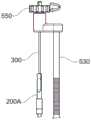
现在参考图16,将更详细地描述具有钻头200A的钻头组件,理解相同的描述适用于钻头200B和钻头200C。钻头200A被示出为具有K氏线300。K氏线300延伸通过从近端202延伸通过钻头200A到远端204的通道208。K氏线300具有近端302、远端304和在近端和远端之间延伸的线体306。远端304具有尖锐的尖端308,该尖端308可以在选定的位置处被冲压到骨中。一旦K氏线300被冲压到骨中,外科医生就可以在K氏线上穿过套管骨螺钉、钻头或其他器械,并将其推进到选定的位置以施行手术。Referring now to FIG. 16 , a drill bit assembly having
K氏线300明显长于钻头200A。因此,K氏线300可以延伸通过钻头200A,其中K氏线的近端302向近端突出并在钻头200A的近端202的外侧。同时,K氏线300可以延伸通过钻头200A,其中K氏线的远端304向远端突出并在钻头200A的远端204的外侧。K氏线300作为允许K氏线和钻头一起钻入骨中的部件可释放地固定在钻头200A内。K's
参考图17和图18,K氏线300在钻打期间通过内置在钻头中的固位机构290可释放地固定到钻头200A的内部。固位机构290被构造成与K氏线300接合,以防止K氏线在钻打期间相对于钻头200A轴向推进。这种固位确保了K氏线300和钻头200A被插入在一起并以相同的量推进到骨中。固位机构290还允许施加到钻头200A的扭矩传递到K氏线300。因此,当固位特征接合时,K氏线300和钻头200A一致地旋转。扭矩驱动器可以对K氏线300和钻头200A一致地施加扭矩,以将K氏线植入骨中并形成用于骨螺钉的导孔。一旦钻打了导孔,钻头200A就可以与K氏线300脱离并从患者身上移除,同时将K氏线留在骨中。Referring to FIGS. 17 and 18 , the K-
固位机构290包括固位夹292,该固位夹292被构造成可释放地与K氏线300的外部上的锁定凹槽308接合。根据本公开的锁定凹槽和固位夹可以具有各种形态和几何形状。例如,锁定凹槽可以围绕K氏线的一部分延伸,或者以圆周方式完全围绕K氏线。固位夹可夹在钻头外部上,或与钻头一体形成。固位夹还可以具有向内延伸的固位端,该固位端可以压入锁定凹槽中以限制K氏线在钻头中的轴向移位。The
固位夹292具有将固位夹附接到钻头200A的毂部294。固位夹292还具有与毂部294相对的固位端296。固位端296通过钻头200的侧壁径向向内突出,以与K氏线300的锁定凹槽308接合。The
根据本公开的K氏线可以在锁定凹槽中具有允许扭矩从钻头/固位夹转移到K氏线的几何形状。例如,K氏线可以在其外部的凹槽中的一部分上具有平坦表面,该平坦表面与固位夹的固位端上的平坦边缘接合。图19示出了具有锁定凹槽308的K氏线300的示例,该锁定凹槽308在凹槽中具有四边方形段310。K氏线300可以搭配形成在根据先前任何示例的钻头中的固位夹工作,例如钻头200A。A K-wire according to the present disclosure may have a geometry in the locking groove that allows torque to be transferred from the bit/retainer clip to the K-wire. For example, the K-wire may have a flat surface on a portion of its outer groove that engages a flat edge on the retention end of the retention clip. FIG. 19 shows an example of a K-
根据本公开的锁定凹槽可以由近端壁和远端壁限定。近端壁和远端壁可以具有控制K氏线相对于周围钻头的轴向移位的不同几何形状。在图19中的示例中,锁定凹槽308具有近端壁312和远端壁314。远端壁314基本上垂直于K氏线300的纵向轴线301。这形成止挡316,当固位夹292接合在锁定凹槽308中时,该止挡316可邻接在固位夹292的固位端296上,从而防止K氏线300在远端方向上的相对移位。与远端壁314相反,近端壁312由相对于纵轴301以锐角延伸的倾斜表面318组成。倾斜表面318形成倾斜段320,该倾斜段320允许固位夹292的固位端296在钻头200A在钻打完成之后从K氏线300取出期间逐渐向外偏转并滑出锁定凹槽308。A locking groove according to the present disclosure may be defined by a proximal wall and a distal wall. The proximal and distal walls may have different geometries that control the axial displacement of the K-wire relative to the surrounding drill bit. In the example in FIG. 19 , locking
固位夹292可在锁定模式和释放模式下操作。如图18所示,在锁定模式中,固位端296被按压并向内固定在锁定凹槽中。这会在钻打期间锁定K氏线300相对于钻头200的轴向位置。在钻打完成之后,可移除固位端296上的向内力,使固位夹292处于释放模式。在释放模式中,可以相对于K氏线300在近端方向上移动钻头200,直到钻头完全从K氏线移除。这允许钻头200A从患者中取出,同时将K氏线300留在患者体内供进一步使用。
参考图20,固位夹292具有部分圆柱形的毂部294,该毂部294被构造成夹在钻头的圆形外部上,类似于笔上的口袋夹。固位夹292还具有位于毂部294和固位端296之间的柔性臂295。柔性臂295允许固位端296在从K氏线中取出钻头时在储存的能量下径向向外弯曲。当钻头从K氏线移除时,固位端296保持在向外位置偏转。一旦钻头从K氏线上移除,固位端296沿径向向内方向卡紧回到图20所示的松弛状态。Referring to FIG. 20, the
力可以沿径向向内的方向施加到固位夹的固位端,以将固位夹压在与锁定凹槽的接合模式中。向内的力可以以多种方式施加。图21和图22示出了具有钻头200'和可移动套筒298'的钻头组件的另一示例。可移动套筒298'可在钻头200'的外部在第一位置和第二位置之间滑动。在第一位置(图21),套筒298'覆盖固位端296',并向其施加向内力,以将固位夹292'固位在接合模式中。在第二位置(图22),套筒298'从固位端296'移开,允许固位端296'向外弯曲,以允许固位夹298'从K氏线300上的锁定凹槽脱离。Force may be applied in a radially inward direction to the retention end of the retention clip to compress the retention clip into engagement mode with the locking groove. The inward force can be applied in a variety of ways. 21 and 22 illustrate another example of a drill bit assembly having a drill bit 200' and a movable sleeve 298'. The movable sleeve 298' is slidable on the exterior of the drill bit 200' between a first position and a second position. In the first position (FIG. 21), the sleeve 298' covers the retention end 296' and applies an inward force thereto to retain the retention clip 292' in the engaged mode. In the second position (FIG. 22), the sleeve 298' is moved away from the retention end 296', allowing the retention end 296' to flex outwardly to allow the retention clip 298' to disengage from the locking groove on the K-
在其他示例中,可使用单独的器械将固位夹锁定到与K氏线接合。图23和图24示出了其中由钻驱动器400将钻头200A的固位夹292维持在接合模式中的示例。钻驱动器400被夹紧在固位夹292的固位端296上,并施加外力以将固位夹292维持在K氏线300的四边锁定凹槽308中的接合模式中。In other examples, a separate instrument may be used to lock the retention clip into engagement with the K-wire. 23 and 24 show an example in which the
钻移除工具drill removal tool
参考图25至图32,示出了根据一个示例的钻移除工具500。钻移除工具500被设计成在钻孔之后从骨移除套管钻头,同时将K氏线留在骨中的适当位置。一旦钻头从K氏线上移除,骨螺钉就可以在K氏线上推进并进入螺钉孔中。钻移除工具500可以搭配钻头、钻管和K氏线的任何组合使用。出于本描述的目的,将描述搭配先前描述的相同钻头200A、钻管150A和K氏线300使用的钻移除工具500。Referring to FIGS. 25-32 , a
钻移除工具500包括第一支撑端510、第二支撑端520和在第一支撑端510和第二支撑端520之间延伸的齿形齿条530。第一支撑端510包括可操作以夹紧到K氏线300上的线夹540。第二支撑端520包括C形基座522,该基座522被构造成紧紧地配合在钻管150A周围。钻头移除器570可在第一支撑端510和第二支撑端520之间的齿形齿条530上轴向移位。The
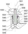
参考图26至图29,线夹540被构造成在解锁状态下穿过K氏线300的暴露端,并随后在锁定状态下夹紧K氏线300。线夹540包括从第一支撑端510延伸的中空壳体542。中空壳体542限定夹通道544,该夹通道544具有近端546、远端548以及在近端546与远端548之间的会聚段549。近端546具有内螺纹547。旋钮550包括拨盘552和具有外螺纹557的轴554,该外螺纹557与夹通道544中的内螺纹547配合。旋钮550限定轴向接收夹紧销560的贯通孔558。夹紧销560在其远端566处限定了贯通通道562和楔形夹头564。夹头564具有向远端566逐渐减小的外径,形成与会聚段549的形状一致的锥形突起。贯通通道562具有适于接收K氏线300的内径。Referring to FIGS. 26 to 29 , the
旋钮550可围绕旋钮轴线551在解锁状态和锁定状态之间旋转。旋钮轴线551与贯通孔558和贯通通道562同轴对准。图27示出了处于解锁状态的旋钮550,并且图28示出了旋转到锁定状态之后的旋钮。当旋钮旋转时,内螺纹547和外螺纹557促进旋钮550的轴向移位。夹紧销560被轴向固定在旋钮550中,其中旋钮550的远端556邻接在夹头564上。在这种布置中,当旋钮旋转时,旋钮550和夹紧销560在夹紧壳体544中一致地轴向移动。内螺纹547和外螺纹557被取向为使得拨盘552在顺时针方向CW上的旋转导致旋钮550和夹头564向远端移动到会聚段549中。当夹紧销560向远端移动时,会聚段549的锥形将向内力施加在夹头564上,压缩夹头564,使得它将K氏线300锁定在锁定状态。The
钻移除工具500可分两步附接在K氏线300、钻头200A和钻管上。在第一步骤中,线夹540穿过K氏线。为了使线夹540穿过K氏线300,旋钮550逆时针旋转到解锁状态,使得夹头564不被压缩在夹通道544的会聚段549中。一旦K氏线300的近端穿过线夹540,第二支撑端520和C形基座522就沿着图26中的弯曲箭头所示的方向朝向钻管150A枢转。C形基座522枢转,直到C形基座中的开口523以紧密配合的方式接收钻管150A。The
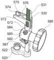
参考图30,钻头移除器570包括限定贯通槽574的叉形砧座572。贯通槽574与夹通道544和开口523对准,形成通过钻移除工具500的所有三个部分的直通道。砧座572在贯通槽574上方具有平坦的叉升表面576。如前所述,贯通槽574和叉升表面576被构造成在止挡表面206下方与钻头200A接合。贯通槽574具有直径略大于钻头200A上的缩径段205但小于扩径段207的圆形端575,该圆形端的直径略大于钻头200A上的缩径段205。因此,砧座572被构造成将钻头200A的缩径段205接收到贯通槽574中,并且叉升表面576相对于止挡表面206定位在下方或远端。在该位置,如图32所示,叉升表面576在止挡表面206处与扩径段207邻接。Referring to FIG. 30 , the drill bit remover 570 includes a forked
钻头移除器570包括连接到砧座572的套筒573。套筒573围绕齿条530并将砧座572与C形基座522互连。小齿轮壳体582从套筒573的一侧延伸并包含小齿轮584。小齿轮584具有多个齿轮齿585,它们通过小齿轮壳体582和齿条530之间的开口与齿条530上的齿531啮合或接合。轮柄586附接到小齿轮584并延伸到小齿轮壳体582的外部。轮柄586和小齿轮584可相对于小齿轮壳体582一致地旋转。在这种布置中,轮柄586可以旋转以沿着齿条530向上或向下移动钻头移除器570。
参考图30和图31,弹簧加载棘爪587可释放地与齿条530上的齿531接合。棘爪587通过弹簧588被偏置成与齿531接合。棘爪587与齿531的接合在钻头移除器570沿着齿条530移位之后自动发生,并且用于锁定钻头移除器570相对于齿条530的位置以维持砧座572的位置。棘爪587抵抗弹簧588的偏置可枢转地脱离与齿531的接合,以释放棘爪587并允许钻头移除器570在齿条530上移动。通过压下从棘爪587延伸的凸片589,棘爪587可以枢转而脱离与齿531的接合。如果需要,弹簧588的强度可以被设计成将棘爪587保持靠着齿条530,但允许棘爪587在轮柄586转动时以棘轮的方式沿着齿条530行驶。可选地,弹簧588的强度可被选择为使得当轮柄586转动时棘爪587不会与齿531脱离,而仅当用户压下凸片589时棘爪587才与齿531脱离。Referring to FIGS. 30 and 31 , spring loaded
当面对轮柄586时,小齿轮584定位在齿条530的左侧上。在这种布置中,轮柄586在顺时针方向CW上的旋转使砧座572向上或朝向第一支撑端510升高。这使得叉升表面576向上或向近端抵靠在钻头200A上的止挡表面206,从而使钻头200A在近端方向上移位。因此,为了从患者处移除钻头200A,而不移除K氏线300,用户首先锁定线夹540以轴向固定K氏线300。然后,用户顺时针旋转轮柄586,以相对于K氏线300在近端方向上移动钻头200A。这具有使钻头200A从患者处取出的效果,同时不使K氏线300移位并使K氏线保持在适当的位置。旋转轮柄586,直到钻头200A的远端204从患者处移除。一旦钻头200A不再在患者体内,线夹540被解锁,并且C形基座522从钻管150A上拆卸。这允许钻移除工具500再次沿着K氏线300移动。然后,将钻头移除工具500从K氏线300抬离,其中叉升表面576支撑钻头200A,使得钻头200A也从K氏线300移除。在从K氏线300移除钻头移除工具500之后,可以从患者以及任何组织扩张器上移除钻管150A。在本示例中,钻管150A延伸通过多个伸缩扩张器,最外层的扩张器D在图32中可见。
在替代MIS技术中,钻头200A可以在没有K氏线300的情况下钻入骨中。在这种情况下,钻移除工具500可用于通过钻头200A将K氏线300插入骨中。为了开始该技术,将诸如先前描述的实施方案的通用钻导附接到导航单元并进行校准。设置钻止挡高度,并将适当的钻管附接到通用钻导。然后将闭塞器插入通用钻导和钻管中并锁定在适当的位置。然后将通用钻导和闭塞器探测到患者体内所需的钻打位置。然后将闭塞器从通用钻导和钻管上移除,并用皮层冲头代替。皮层冲头用于在皮层上创建起始孔,然后移除。然后将合适的钻头附接到驱动器,插入通用钻导中,并通过钻管向前推进,以在骨头中钻打孔。一旦钻头钻入骨中,通用钻导就从钻管上拆卸和移除,使钻头和钻管就位。In an alternative MIS technique,
组织扩张器D附接到扩张器手柄并在钻管上推进,直到它接触钻管周围的组织。扩张器然后被推动和旋转以扩张组织。然后在扩张器上推进组织保护器P。然后可以通过钻头将K氏线插入骨中。The tissue expander D is attached to the dilator handle and advanced over the drill tube until it contacts the tissue surrounding the drill tube. The dilator is then pushed and rotated to expand the tissue. Tissue protector P is then advanced over the dilator. The K-wire can then be inserted into the bone through a drill.
参考图46至图52,示出了用于将K氏线300插入钻头200A的一个过程。在第一步骤中,K氏线300被装载到钻移除工具500中。旋钮550旋转到解锁位置,并且K氏线300在图46中箭头所示的方向上插入通过旋钮。K氏线300通过旋钮550推进,直到K氏线上的长标记303被钻移除工具500完全覆盖。一旦K氏线300通过钻移除工具500推进到适当位置,旋钮550就旋转到如图47中箭头所示的锁定位置,以将K氏线锁定在线夹540中。Referring to FIGS. 46-52 , one process for inserting the K-
钻移除工具500和K氏线300定位在钻头200A的近端202上。然后将K氏线300向下引导到钻头200A中。如图48所示,钻移除工具500的底部朝向钻头200A和扩张器D枢转,直到钻头被接收在砧座572的贯通槽574中。钻移除工具500枢转,同时确保砧座572位于止挡表面206下方。一旦将钻移除工具500被安装到钻头200A和扩张器D上,旋钮550就沿着图49所示的方向旋转到解锁位置。
如图50所示,K氏线300向下推进到钻头200A中。如图51所示,一旦长标记303被钻头200A完全覆盖,旋钮550就旋转到锁定位置。然后,如图52所示,轮柄586旋转,以相对于齿形齿条530向上移动砧座572并将钻头200A从骨中拔出。一旦钻头200A从骨中拔出,钻移除工具500和钻头就可以被抬升和移除。然后如图53所示,可以从保护器P上移除钻管150A和扩张器D。As shown in Figure 50, the K-
具有K氏线固位的骨螺钉驱动器Bone Screw Driver with K-Wire Retention
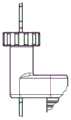
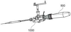
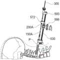
参考图33至图41,示出了根据一个示例的具有骨螺钉驱动器600的骨螺钉驱动器组件。骨螺钉驱动器600被设计成在K氏线上推进骨螺钉并将骨螺钉驱动到骨中,同时防止K氏线向前(即远端)推进。为了实现这一点,骨螺钉驱动器组件具有K氏线固位模块700。出于本描述的目的,将描述骨螺钉驱动器600和K氏线固位模块700搭配先前描述的相同K氏线300使用的情况。Referring to FIGS. 33-41 , a bone screw driver assembly having a
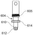
骨螺钉驱动器600具有轴601,该轴601限定近端602、与近端602相对的远端604,以及近端602和远端604之间的纵向贯通通道606。通道606被构造成使得骨螺钉驱动器600可以穿过K氏线300的近端并朝向K氏线300的远端推进。近端602具有附接机构(不可见),手柄603附接在该附接机构上。附接机构可以是用于接收手柄的任何合适的结构,包括但不限于六角形轴。手柄603被构造成被用户抓握并旋转以操作骨螺钉驱动器600,非常类似于常规螺钉驱动器。远端604具有外螺纹605,该外螺纹605被构造成与椎弓根螺钉组件的棒接收部件中的内螺纹配合。旋钮607设置在轴601上,以便于轴601旋转以将外螺纹605螺纹到棒接收部件中。
参考图34和图35,远端604具有驱动器尖端610。驱动器尖端610具有六角形延伸部612,该六角形延伸部612配合到骨螺钉头部中类似形状的槽中。驱动器尖端610还具有相对于延伸部612位于近端的一对凸尾614。当外螺纹605被螺纹到棒接收部件的内螺纹中时,凸尾614被构造成滑入棒接收部件中的直径相对狭槽中。在这种布置中,凸尾614占据固定棒将位于的位置。Referring to FIGS. 34 and 35 , the
K氏线固位模块700包括壳体710,该壳体710具有近端712、远端714和在近端712和远端714之间延伸的通道716。通道716与骨螺钉驱动器600的通道606对准。在这种布置中,骨螺钉驱动器600和K氏线固位模块700可以作为整体在K氏线300上推进。图36示出了骨螺钉驱动器600(没有附接手柄603)被推进到植入的K氏线300上的过程。驱动器尖端610被固定到同样穿过K氏线的套管多轴螺钉组件800和凸片保护套筒850。The K-
参考图37,K氏线固位模块700具有容纳在壳体710内的辊组件720。辊组件720可在脱离模式和接合(或驱动)模式下操作。在脱离模式中,辊组件720允许K氏线固位模块700和骨螺钉驱动器600沿着K氏线300的长度自由推进。在接合模式中,辊组件720与K氏线300接合,并且当骨螺钉驱动器600在远端方向上推进多轴螺钉组件800时,在近端方向上通过壳体710馈送K氏线300。Referring to FIG. 37 , a K-
辊组件720包括附接到骨螺钉驱动器600的轴601上的第一直齿轮722a,以及与第一直齿轮722a配合的第二直齿轮722b。辊组件720还包括在轴601上与第四直齿轮722d配合的第三直齿轮722c。第二直齿轮722b和第四直齿轮722d附接到平行于轴601延伸的副轴721。副轴721具有与第五直齿轮722e配合的蜗齿轮724。第五直齿轮722e附接在第一辊726上,该第一辊726固定在第五直齿轮722e上,使得第五直齿轮722e和第一辊726一致旋转。第二辊728在与第一辊726相对的一侧上与K氏线300接合的位置处邻近第一辊726定位。The
参考图38至图41,辊组件720的接合和脱离由杠组件730控制。杠组件730包括弹簧加载杆732,其通过压缩弹簧734向接合模式偏置。图38示出了即将在K氏线300上推进的辊组件720的部件。杆732通过弹簧734定位在接合模式中,弹簧734被完全展开。在该模式中,第一辊726和第二辊728被紧密地定位在一起,它们之间的间隙很小或没有间隙。如图40所示,为了使辊组件720在K氏线300上推进,杆732被向内压向K氏线。这使第一辊726和第二辊728分开,允许辊组件720在K氏线300上推进。一旦K氏线300被接收在第一辊726和第二辊728之间,就可以释放杆732,以允许辊组件720在弹簧734的偏置下返回到接合模式,将辊定位为与K氏线直接接合。Referring to FIGS. 38-41 , the engagement and disengagement of the
通过向骨螺钉驱动器600的近端602施加顺时针扭矩,将多轴螺钉组件800通过K氏线300驱动到骨中。当顺时针扭矩被施加到螺钉驱动器600的近端602且辊组件720处于接合模式时,辊组件720将在近端方向上通过壳体710馈送K氏线300。轴601的顺时针旋转使第一直齿轮722a和第三直齿轮722c沿顺时针方向旋转,这又通过第二直齿轮722c和第四直齿轮722d向副轴721传递扭矩。副轴721和蜗齿轮724沿逆时针方向旋转,这将扭矩传递给第五直齿轮722e。第五直齿轮722e在第一方向上驱动第一辊726。第二辊728被偏置成与K氏线300接合,并在与第一方向相反的第二方向上旋转。第一辊726和第二辊728的外表面夹持K氏线300的表面,以在相对于壳体710的近端方向上牵引K氏线,使得当多轴螺钉组件800被远端驱动到骨中时,K氏线300被近端馈送。By applying a clockwise torque to the
通过棘轮742和棘爪744防止K氏线300通过壳体710的远端馈送。如图39所示,棘爪744与棘轮742接合,以防止轴601相对于壳体710逆时针旋转,这将使第一辊726和第二辊728在向远端馈送K氏线的相反方向上旋转。如图41所示,通过将杆732向内压靠弹簧724,棘爪744可以枢转而脱离与棘轮742的接合。这将辊组件720切换到脱离模式并释放K氏线300,允许骨螺钉驱动器600和K氏线固位模块700从K氏线300移除,而没有向远端推进K氏线300的风险。Feeding of K-
根据本公开的K氏线固位模块可以是可拆卸地连接到不同类型的器械的模块化单元,包括但不限于用于攻丝和驱动的器械。在本示例中,K氏线固位模块700通过图33所示的快速配合连接650可拆卸地连接到骨螺钉驱动器600。骨螺钉驱动器600的轴601使用快速配合连接650卡入壳体710中,该快速配合连接650可以是控制旋转的六角驱动、1/4英寸驱动或AO驱动。A K-wire retention module according to the present disclosure may be a modular unit that is detachably attachable to different types of instruments, including but not limited to instruments for threading and driving. In this example, K-
根据本公开的骨螺钉驱动器可以包括用于帮助骨螺钉插入的各种类型的标记。例如,轴601可以具有提供类似于通用钻导110上的深度标记的深度标记的间隔线。深度标记可以为用户提供骨螺钉尖端推进到的深度的可视指示。骨螺钉驱动器还可以包括各种特征,以帮助杀菌。例如,轴601具有一系列孔611,允许蒸汽在高压灭菌和清洁期间进入轴601的内部。Bone screw drivers according to the present disclosure may include various types of markings to aid in bone screw insertion. For example, the
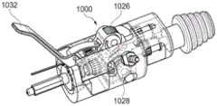
图42至图45示出了根据另一实施方案的替代骨螺钉驱动器900和K氏线固位模块1000。K氏线固位模块1000类似于K氏线固位模块700,但是特征在于夹持杆1032和夹持辊1026、1028。夹持杆1032通常处于打开位置以分离夹持辊1026、1028,如图43和图44所示。夹持杆1032可移动到闭合位置,如图45所示,以与靠在K氏线300上的辊接合。当K氏线300位于压紧辊1026、1028之间时,压紧杆1032只能保持闭合(即驱动器只能保持接合)。42-45 illustrate an alternative
本文所述的器械可以使用各种材料制造,包括但不限于各种不锈钢合金。合金等级可以根据所需的强度、硬度、耐腐蚀性、磨损性能和其他性能标准来选择。The devices described herein can be fabricated using a variety of materials including, but not limited to, various stainless steel alloys. Alloy grades can be selected based on desired strength, hardness, corrosion resistance, wear properties and other performance criteria.
Claims (12)
Translated fromChineseApplications Claiming Priority (3)
| Application Number | Priority Date | Filing Date | Title |
|---|---|---|---|
| US202062970850P | 2020-02-06 | 2020-02-06 | |
| US62/970,850 | 2020-02-06 | ||
| PCT/EP2021/052719WO2021156395A1 (en) | 2020-02-06 | 2021-02-04 | Universal drill guide system |
Publications (2)
| Publication Number | Publication Date |
|---|---|
| CN115052536A CN115052536A (en) | 2022-09-13 |
| CN115052536Btrue CN115052536B (en) | 2023-06-02 |
Family
ID=74556670
Family Applications (3)
| Application Number | Title | Priority Date | Filing Date |
|---|---|---|---|
| CN202180012140.9AActiveCN115066215B (en) | 2020-02-06 | 2021-02-04 | Drill removal tool |
| CN202180012885.5APendingCN115279285A (en) | 2020-02-06 | 2021-02-04 | Universal drill guide system |
| CN202180012910.XAActiveCN115052536B (en) | 2020-02-06 | 2021-02-04 | Universal Drill Guide System |
Family Applications Before (2)
| Application Number | Title | Priority Date | Filing Date |
|---|---|---|---|
| CN202180012140.9AActiveCN115066215B (en) | 2020-02-06 | 2021-02-04 | Drill removal tool |
| CN202180012885.5APendingCN115279285A (en) | 2020-02-06 | 2021-02-04 | Universal drill guide system |
Country Status (6)
| Country | Link |
|---|---|
| US (1) | US11759280B2 (en) |
| EP (5) | EP4099923B1 (en) |
| JP (3) | JP7580471B2 (en) |
| CN (3) | CN115066215B (en) |
| ES (5) | ES3032939T3 (en) |
| WO (3) | WO2021156394A1 (en) |
Families Citing this family (7)
| Publication number | Priority date | Publication date | Assignee | Title |
|---|---|---|---|---|
| US12262927B2 (en)* | 2020-12-10 | 2025-04-01 | K2M, Inc. | Screw insertion instrument and methods of use |
| WO2023102423A1 (en)* | 2021-12-01 | 2023-06-08 | Foley Kevin T | Guidewire retention mechanism |
| DE102022104674A1 (en)* | 2022-02-28 | 2023-08-31 | Aesculap Ag | Medical drilling device and medical drilling system |
| CN114704214B (en)* | 2022-06-07 | 2022-09-02 | 西南石油大学 | Drill bit fastening and clamping structure and method |
| US12329418B2 (en) | 2022-07-26 | 2025-06-17 | Globus Medical Inc. | Minimally invasive surgery guide wire capturing instrumentation |
| DE102023118429A1 (en)* | 2023-07-12 | 2025-01-16 | Aesculap Ag | preparation instrument for preparing a bone |
| WO2025064874A1 (en)* | 2023-09-20 | 2025-03-27 | Paragon 28, Inc. | Right angle drill, instrumentation, system and methods of use and assembly |
Citations (7)
| Publication number | Priority date | Publication date | Assignee | Title |
|---|---|---|---|---|
| US4850755A (en)* | 1987-04-03 | 1989-07-25 | British Aerospace Plc | Nose piece adaptors for manual or power feed drills |
| CN1142753A (en)* | 1993-12-15 | 1997-02-12 | 詹姆斯·布鲁斯·理查森 | Patient-operated orthopedic device |
| CN1735485A (en)* | 2001-10-26 | 2006-02-15 | 布莱克-德克尔公司 | Drilling and/or hammering tools |
| EP2502693A1 (en)* | 2011-03-21 | 2012-09-26 | wolfcraft GmbH | Quick change adapter for a hole saw |
| CN103038009A (en)* | 2010-04-20 | 2013-04-10 | L.S.施泰力公司 | Hole saw arbor system |
| CN104039252A (en)* | 2011-07-08 | 2014-09-10 | 史密夫和内修有限公司 | Orthopedic instruments |
| CN104619270A (en)* | 2012-09-14 | 2015-05-13 | 新特斯有限责任公司 | Porous Drill Bushing with Protective Sleeve |
Family Cites Families (32)
| Publication number | Priority date | Publication date | Assignee | Title |
|---|---|---|---|---|
| CA2155422C (en)* | 1993-02-10 | 2005-07-12 | Stephen D. Kuslich | Spinal stabilization surgical method |
| US6716215B1 (en)* | 1999-10-29 | 2004-04-06 | Image-Guided Neurologics | Cranial drill with sterile barrier |
| AUPR524901A0 (en)* | 2001-05-24 | 2001-06-21 | Hills Industries Limited | Guide mechanism for power drill |
| US6827722B1 (en)* | 2001-12-11 | 2004-12-07 | Biomet, Inc. | Method and apparatus for use of a guide wire capturing surgical instrument |
| US7357804B2 (en)* | 2003-08-13 | 2008-04-15 | Synthes (U.S.A.) | Quick-release drill-guide assembly for bone-plate |
| AU2004283727A1 (en)* | 2003-10-23 | 2005-05-06 | Trans1 Inc. | Tools and tool kits for performing minimally invasive procedures on the spine |
| US7207995B1 (en)* | 2004-01-29 | 2007-04-24 | Biomer Manufacturing Corp. | Method and apparatus for retaining a guide wire |
| US7163542B2 (en)* | 2004-03-30 | 2007-01-16 | Synthes (U.S.A.) | Adjustable depth drill bit |
| US8109934B2 (en)* | 2005-02-10 | 2012-02-07 | Zimmer Spine, Inc. | All through one drill guide for cervical plating |
| EP2151202B1 (en)* | 2008-08-04 | 2011-02-16 | BrainLAB AG | Clamping piece for clamping a cannulated drill and a guide wire |
| CA2792997A1 (en) | 2010-03-23 | 2011-09-29 | Geisinger Clinic | Diagnostic device for determining mechanical integrity of bone |
| US11039889B2 (en)* | 2010-06-29 | 2021-06-22 | Mighty Oak Medical, Inc. | Patient-matched apparatus and methods for performing surgical procedures |
| WO2012046210A1 (en)* | 2010-10-07 | 2012-04-12 | Miami Device Solutions, Llc | Bone plate assembly with guide member |
| MX348238B (en)* | 2011-03-09 | 2017-05-29 | Smith & Nephew Inc | Multiple portal guide. |
| EP2849656B1 (en)* | 2012-05-14 | 2017-10-04 | Synthes GmbH | Bone access instrument |
| DE102012104207A1 (en)* | 2012-05-15 | 2013-12-05 | Ulrich Gmbh & Co. Kg | assembly tool |
| US20140088647A1 (en)* | 2012-09-21 | 2014-03-27 | Atlas Spine, Inc. | Minimally invasive spine surgery instruments: spinal rod with flange |
| EP2956072B1 (en)* | 2013-02-13 | 2019-12-18 | Synthes GmbH | Pedicle screw engaging control instrument with a guidewire capturing system |
| US9433445B2 (en)* | 2013-03-14 | 2016-09-06 | DePuy Synthes Products, Inc. | Bone anchors and surgical instruments with integrated guide tips |
| US9254160B2 (en)* | 2013-03-14 | 2016-02-09 | Aesculap Implant Systems, Llc | Driver assembly with guidewire control mechanism |
| US20140276880A1 (en)* | 2013-03-15 | 2014-09-18 | Blackstone Medical, Inc. | Locking assembly for a surgical drill bit guide |
| US9439658B2 (en)* | 2013-05-14 | 2016-09-13 | SpineDriver, LLC | Drill bit package assembly |
| WO2015006296A1 (en)* | 2013-07-09 | 2015-01-15 | Stryker Corporation | Surgical drill having brake that, upon the drill bit penetrating through bone, prevents further insertion of the drill bit |
| US20160199072A1 (en) | 2013-08-19 | 2016-07-14 | Smith & Nephew, Inc. | Bone removal under direct visualization |
| US9427274B1 (en)* | 2013-10-17 | 2016-08-30 | Z'egist Solutions, LLC | Surgical cutting system and method |
| US9427271B2 (en)* | 2014-03-18 | 2016-08-30 | Osteomed Llc | Percutaneous exchange tube and method of use |
| US10080583B2 (en)* | 2014-12-12 | 2018-09-25 | Depuy Mitel, Llc | Dilator for accessing a joint space |
| WO2016204711A1 (en)* | 2015-06-16 | 2016-12-22 | Spine Wave, Inc. | Instrument and system for placing graft, implant and graft material for minimally invasive posterolateral fusion |
| JP2018532498A (en)* | 2015-10-14 | 2018-11-08 | マイティ オーク メディカル、インコーポレイテッド | Patient fitting device and method of performing a surgical procedure |
| US10987116B2 (en)* | 2017-12-15 | 2021-04-27 | Medos International Sarl | Adjustable drill guides and related methods |
| AU2019231188B2 (en)* | 2018-03-05 | 2021-02-11 | Edge Surgical, Inc. | Handheld devices for use in medical procedures |
| CN208644148U (en)* | 2018-04-24 | 2019-03-26 | 米沃奇电动工具公司 | Electric drill rack |
- 2021
- 2021-02-01USUS17/164,145patent/US11759280B2/enactiveActive
- 2021-02-04ESES21704725Tpatent/ES3032939T3/enactiveActive
- 2021-02-04EPEP21704725.7Apatent/EP4099923B1/enactiveActive
- 2021-02-04WOPCT/EP2021/052718patent/WO2021156394A1/ennot_activeCeased
- 2021-02-04ESES21155339Tpatent/ES2924757T3/enactiveActive
- 2021-02-04ESES21704456Tpatent/ES2960328T3/enactiveActive
- 2021-02-04CNCN202180012140.9Apatent/CN115066215B/enactiveActive
- 2021-02-04EPEP21155339.1Apatent/EP3861940B1/enactiveActive
- 2021-02-04EPEP21155340.9Apatent/EP3861941B1/enactiveActive
- 2021-02-04WOPCT/EP2021/052720patent/WO2021156396A1/ennot_activeCeased
- 2021-02-04ESES21155340Tpatent/ES2992101T3/enactiveActive
- 2021-02-04JPJP2022546708Apatent/JP7580471B2/enactiveActive
- 2021-02-04CNCN202180012885.5Apatent/CN115279285A/enactivePending
- 2021-02-04JPJP2022546710Apatent/JP7580472B2/enactiveActive
- 2021-02-04ESES21704457Tpatent/ES3032867T3/enactiveActive
- 2021-02-04JPJP2022546711Apatent/JP7640566B2/enactiveActive
- 2021-02-04EPEP21704457.7Apatent/EP4099930B1/enactiveActive
- 2021-02-04WOPCT/EP2021/052719patent/WO2021156395A1/ennot_activeCeased
- 2021-02-04CNCN202180012910.XApatent/CN115052536B/enactiveActive
- 2021-02-04EPEP21704456.9Apatent/EP4099925B1/enactiveActive
Patent Citations (7)
| Publication number | Priority date | Publication date | Assignee | Title |
|---|---|---|---|---|
| US4850755A (en)* | 1987-04-03 | 1989-07-25 | British Aerospace Plc | Nose piece adaptors for manual or power feed drills |
| CN1142753A (en)* | 1993-12-15 | 1997-02-12 | 詹姆斯·布鲁斯·理查森 | Patient-operated orthopedic device |
| CN1735485A (en)* | 2001-10-26 | 2006-02-15 | 布莱克-德克尔公司 | Drilling and/or hammering tools |
| CN103038009A (en)* | 2010-04-20 | 2013-04-10 | L.S.施泰力公司 | Hole saw arbor system |
| EP2502693A1 (en)* | 2011-03-21 | 2012-09-26 | wolfcraft GmbH | Quick change adapter for a hole saw |
| CN104039252A (en)* | 2011-07-08 | 2014-09-10 | 史密夫和内修有限公司 | Orthopedic instruments |
| CN104619270A (en)* | 2012-09-14 | 2015-05-13 | 新特斯有限责任公司 | Porous Drill Bushing with Protective Sleeve |
Also Published As
| Publication number | Publication date |
|---|---|
| CN115052536A (en) | 2022-09-13 |
| WO2021156395A1 (en) | 2021-08-12 |
| ES2924757T3 (en) | 2022-10-10 |
| ES2992101T3 (en) | 2024-12-09 |
| CN115066215A (en) | 2022-09-16 |
| EP3861940A1 (en) | 2021-08-11 |
| EP4099930B1 (en) | 2025-04-02 |
| EP3861941A1 (en) | 2021-08-11 |
| JP2023513883A (en) | 2023-04-04 |
| JP7580471B2 (en) | 2024-11-11 |
| EP4099930A1 (en) | 2022-12-14 |
| JP7580472B2 (en) | 2024-11-11 |
| CN115279285A (en) | 2022-11-01 |
| WO2021156396A1 (en) | 2021-08-12 |
| JP2023513884A (en) | 2023-04-04 |
| JP7640566B2 (en) | 2025-03-05 |
| WO2021156394A1 (en) | 2021-08-12 |
| EP4099925A1 (en) | 2022-12-14 |
| EP4099925B1 (en) | 2023-07-19 |
| JP2023513882A (en) | 2023-04-04 |
| ES3032867T3 (en) | 2025-07-28 |
| CN115066215B (en) | 2023-08-08 |
| EP3861940B1 (en) | 2022-05-25 |
| ES2960328T3 (en) | 2024-03-04 |
| EP4099923A1 (en) | 2022-12-14 |
| ES3032939T3 (en) | 2025-07-29 |
| EP3861941B1 (en) | 2024-08-21 |
| EP4099923B1 (en) | 2025-04-09 |
| US20210244424A1 (en) | 2021-08-12 |
| US11759280B2 (en) | 2023-09-19 |
Similar Documents
| Publication | Publication Date | Title |
|---|---|---|
| CN115052536B (en) | Universal Drill Guide System | |
| US11337736B2 (en) | Driver instruments and related methods | |
| CN101128158B (en) | Less invasive surgical systems and methods | |
| US7621916B2 (en) | Cervical bone preparation tool and implant guide systems | |
| US20060004398A1 (en) | Sequential dilator system | |
| JP2006508755A (en) | Surgical retractor system | |
| WO2007124130A2 (en) | Method and apparatus for spinal fixation | |
| US12329416B2 (en) | Reamer instruments and related methods | |
| EP4011306B1 (en) | Screw insertion instrument | |
| US20240050105A1 (en) | Systems and methods for providing access to within bony anatomy | |
| EP3892215B1 (en) | Surgical instrument |
Legal Events
| Date | Code | Title | Description |
|---|---|---|---|
| PB01 | Publication | ||
| PB01 | Publication | ||
| SE01 | Entry into force of request for substantive examination | ||
| SE01 | Entry into force of request for substantive examination | ||
| GR01 | Patent grant | ||
| GR01 | Patent grant |