CN115038411A - Vertebral implant and method for manufacturing vertebral implant - Google Patents
Vertebral implant and method for manufacturing vertebral implantDownload PDFInfo
- Publication number
- CN115038411A CN115038411ACN202180010342.XACN202180010342ACN115038411ACN 115038411 ACN115038411 ACN 115038411ACN 202180010342 ACN202180010342 ACN 202180010342ACN 115038411 ACN115038411 ACN 115038411A
- Authority
- CN
- China
- Prior art keywords
- region
- spinal implant
- coating
- base body
- implant according
- Prior art date
- Legal status (The legal status is an assumption and is not a legal conclusion. Google has not performed a legal analysis and makes no representation as to the accuracy of the status listed.)
- Pending
Links
Images


Classifications
- A—HUMAN NECESSITIES
- A61—MEDICAL OR VETERINARY SCIENCE; HYGIENE
- A61F—FILTERS IMPLANTABLE INTO BLOOD VESSELS; PROSTHESES; DEVICES PROVIDING PATENCY TO, OR PREVENTING COLLAPSING OF, TUBULAR STRUCTURES OF THE BODY, e.g. STENTS; ORTHOPAEDIC, NURSING OR CONTRACEPTIVE DEVICES; FOMENTATION; TREATMENT OR PROTECTION OF EYES OR EARS; BANDAGES, DRESSINGS OR ABSORBENT PADS; FIRST-AID KITS
- A61F2/00—Filters implantable into blood vessels; Prostheses, i.e. artificial substitutes or replacements for parts of the body; Appliances for connecting them with the body; Devices providing patency to, or preventing collapsing of, tubular structures of the body, e.g. stents
- A61F2/02—Prostheses implantable into the body
- A61F2/30—Joints
- A61F2/44—Joints for the spine, e.g. vertebrae, spinal discs
- A61F2/4455—Joints for the spine, e.g. vertebrae, spinal discs for the fusion of spinal bodies, e.g. intervertebral fusion of adjacent spinal bodies, e.g. fusion cages
- A61F2/447—Joints for the spine, e.g. vertebrae, spinal discs for the fusion of spinal bodies, e.g. intervertebral fusion of adjacent spinal bodies, e.g. fusion cages substantially parallelepipedal, e.g. having a rectangular or trapezoidal cross-section
- A—HUMAN NECESSITIES
- A61—MEDICAL OR VETERINARY SCIENCE; HYGIENE
- A61F—FILTERS IMPLANTABLE INTO BLOOD VESSELS; PROSTHESES; DEVICES PROVIDING PATENCY TO, OR PREVENTING COLLAPSING OF, TUBULAR STRUCTURES OF THE BODY, e.g. STENTS; ORTHOPAEDIC, NURSING OR CONTRACEPTIVE DEVICES; FOMENTATION; TREATMENT OR PROTECTION OF EYES OR EARS; BANDAGES, DRESSINGS OR ABSORBENT PADS; FIRST-AID KITS
- A61F2/00—Filters implantable into blood vessels; Prostheses, i.e. artificial substitutes or replacements for parts of the body; Appliances for connecting them with the body; Devices providing patency to, or preventing collapsing of, tubular structures of the body, e.g. stents
- A61F2/02—Prostheses implantable into the body
- A61F2/30—Joints
- A61F2/30767—Special external or bone-contacting surface, e.g. coating for improving bone ingrowth
- A61F2/30771—Special external or bone-contacting surface, e.g. coating for improving bone ingrowth applied in original prostheses, e.g. holes or grooves
- A—HUMAN NECESSITIES
- A61—MEDICAL OR VETERINARY SCIENCE; HYGIENE
- A61F—FILTERS IMPLANTABLE INTO BLOOD VESSELS; PROSTHESES; DEVICES PROVIDING PATENCY TO, OR PREVENTING COLLAPSING OF, TUBULAR STRUCTURES OF THE BODY, e.g. STENTS; ORTHOPAEDIC, NURSING OR CONTRACEPTIVE DEVICES; FOMENTATION; TREATMENT OR PROTECTION OF EYES OR EARS; BANDAGES, DRESSINGS OR ABSORBENT PADS; FIRST-AID KITS
- A61F2/00—Filters implantable into blood vessels; Prostheses, i.e. artificial substitutes or replacements for parts of the body; Appliances for connecting them with the body; Devices providing patency to, or preventing collapsing of, tubular structures of the body, e.g. stents
- A61F2/02—Prostheses implantable into the body
- A61F2/30—Joints
- A61F2/46—Special tools for implanting artificial joints
- A61F2/4603—Special tools for implanting artificial joints for insertion or extraction of endoprosthetic joints or of accessories thereof
- A61F2/4611—Special tools for implanting artificial joints for insertion or extraction of endoprosthetic joints or of accessories thereof of spinal prostheses
- A—HUMAN NECESSITIES
- A61—MEDICAL OR VETERINARY SCIENCE; HYGIENE
- A61F—FILTERS IMPLANTABLE INTO BLOOD VESSELS; PROSTHESES; DEVICES PROVIDING PATENCY TO, OR PREVENTING COLLAPSING OF, TUBULAR STRUCTURES OF THE BODY, e.g. STENTS; ORTHOPAEDIC, NURSING OR CONTRACEPTIVE DEVICES; FOMENTATION; TREATMENT OR PROTECTION OF EYES OR EARS; BANDAGES, DRESSINGS OR ABSORBENT PADS; FIRST-AID KITS
- A61F2/00—Filters implantable into blood vessels; Prostheses, i.e. artificial substitutes or replacements for parts of the body; Appliances for connecting them with the body; Devices providing patency to, or preventing collapsing of, tubular structures of the body, e.g. stents
- A61F2/02—Prostheses implantable into the body
- A61F2/30—Joints
- A61F2002/30001—Additional features of subject-matter classified in A61F2/28, A61F2/30 and subgroups thereof
- A61F2002/30003—Material related properties of the prosthesis or of a coating on the prosthesis
- A61F2002/3006—Properties of materials and coating materials
- A—HUMAN NECESSITIES
- A61—MEDICAL OR VETERINARY SCIENCE; HYGIENE
- A61F—FILTERS IMPLANTABLE INTO BLOOD VESSELS; PROSTHESES; DEVICES PROVIDING PATENCY TO, OR PREVENTING COLLAPSING OF, TUBULAR STRUCTURES OF THE BODY, e.g. STENTS; ORTHOPAEDIC, NURSING OR CONTRACEPTIVE DEVICES; FOMENTATION; TREATMENT OR PROTECTION OF EYES OR EARS; BANDAGES, DRESSINGS OR ABSORBENT PADS; FIRST-AID KITS
- A61F2/00—Filters implantable into blood vessels; Prostheses, i.e. artificial substitutes or replacements for parts of the body; Appliances for connecting them with the body; Devices providing patency to, or preventing collapsing of, tubular structures of the body, e.g. stents
- A61F2/02—Prostheses implantable into the body
- A61F2/30—Joints
- A61F2002/30001—Additional features of subject-matter classified in A61F2/28, A61F2/30 and subgroups thereof
- A61F2002/30316—The prosthesis having different structural features at different locations within the same prosthesis; Connections between prosthetic parts; Special structural features of bone or joint prostheses not otherwise provided for
- A61F2002/30535—Special structural features of bone or joint prostheses not otherwise provided for
- A61F2002/30593—Special structural features of bone or joint prostheses not otherwise provided for hollow
- A—HUMAN NECESSITIES
- A61—MEDICAL OR VETERINARY SCIENCE; HYGIENE
- A61F—FILTERS IMPLANTABLE INTO BLOOD VESSELS; PROSTHESES; DEVICES PROVIDING PATENCY TO, OR PREVENTING COLLAPSING OF, TUBULAR STRUCTURES OF THE BODY, e.g. STENTS; ORTHOPAEDIC, NURSING OR CONTRACEPTIVE DEVICES; FOMENTATION; TREATMENT OR PROTECTION OF EYES OR EARS; BANDAGES, DRESSINGS OR ABSORBENT PADS; FIRST-AID KITS
- A61F2/00—Filters implantable into blood vessels; Prostheses, i.e. artificial substitutes or replacements for parts of the body; Appliances for connecting them with the body; Devices providing patency to, or preventing collapsing of, tubular structures of the body, e.g. stents
- A61F2/02—Prostheses implantable into the body
- A61F2/30—Joints
- A61F2/30767—Special external or bone-contacting surface, e.g. coating for improving bone ingrowth
- A61F2/30771—Special external or bone-contacting surface, e.g. coating for improving bone ingrowth applied in original prostheses, e.g. holes or grooves
- A61F2002/30772—Apertures or holes, e.g. of circular cross section
- A61F2002/30774—Apertures or holes, e.g. of circular cross section internally-threaded
- A—HUMAN NECESSITIES
- A61—MEDICAL OR VETERINARY SCIENCE; HYGIENE
- A61F—FILTERS IMPLANTABLE INTO BLOOD VESSELS; PROSTHESES; DEVICES PROVIDING PATENCY TO, OR PREVENTING COLLAPSING OF, TUBULAR STRUCTURES OF THE BODY, e.g. STENTS; ORTHOPAEDIC, NURSING OR CONTRACEPTIVE DEVICES; FOMENTATION; TREATMENT OR PROTECTION OF EYES OR EARS; BANDAGES, DRESSINGS OR ABSORBENT PADS; FIRST-AID KITS
- A61F2/00—Filters implantable into blood vessels; Prostheses, i.e. artificial substitutes or replacements for parts of the body; Appliances for connecting them with the body; Devices providing patency to, or preventing collapsing of, tubular structures of the body, e.g. stents
- A61F2/02—Prostheses implantable into the body
- A61F2/30—Joints
- A61F2/30767—Special external or bone-contacting surface, e.g. coating for improving bone ingrowth
- A61F2/30771—Special external or bone-contacting surface, e.g. coating for improving bone ingrowth applied in original prostheses, e.g. holes or grooves
- A61F2002/30904—Special external or bone-contacting surface, e.g. coating for improving bone ingrowth applied in original prostheses, e.g. holes or grooves serrated profile, i.e. saw-toothed
- A—HUMAN NECESSITIES
- A61—MEDICAL OR VETERINARY SCIENCE; HYGIENE
- A61F—FILTERS IMPLANTABLE INTO BLOOD VESSELS; PROSTHESES; DEVICES PROVIDING PATENCY TO, OR PREVENTING COLLAPSING OF, TUBULAR STRUCTURES OF THE BODY, e.g. STENTS; ORTHOPAEDIC, NURSING OR CONTRACEPTIVE DEVICES; FOMENTATION; TREATMENT OR PROTECTION OF EYES OR EARS; BANDAGES, DRESSINGS OR ABSORBENT PADS; FIRST-AID KITS
- A61F2/00—Filters implantable into blood vessels; Prostheses, i.e. artificial substitutes or replacements for parts of the body; Appliances for connecting them with the body; Devices providing patency to, or preventing collapsing of, tubular structures of the body, e.g. stents
- A61F2/02—Prostheses implantable into the body
- A61F2/30—Joints
- A61F2/30767—Special external or bone-contacting surface, e.g. coating for improving bone ingrowth
- A61F2002/3093—Special external or bone-contacting surface, e.g. coating for improving bone ingrowth for promoting ingrowth of bone tissue
- A—HUMAN NECESSITIES
- A61—MEDICAL OR VETERINARY SCIENCE; HYGIENE
- A61F—FILTERS IMPLANTABLE INTO BLOOD VESSELS; PROSTHESES; DEVICES PROVIDING PATENCY TO, OR PREVENTING COLLAPSING OF, TUBULAR STRUCTURES OF THE BODY, e.g. STENTS; ORTHOPAEDIC, NURSING OR CONTRACEPTIVE DEVICES; FOMENTATION; TREATMENT OR PROTECTION OF EYES OR EARS; BANDAGES, DRESSINGS OR ABSORBENT PADS; FIRST-AID KITS
- A61F2/00—Filters implantable into blood vessels; Prostheses, i.e. artificial substitutes or replacements for parts of the body; Appliances for connecting them with the body; Devices providing patency to, or preventing collapsing of, tubular structures of the body, e.g. stents
- A61F2/02—Prostheses implantable into the body
- A61F2/30—Joints
- A61F2/3094—Designing or manufacturing processes
- A61F2/30942—Designing or manufacturing processes for designing or making customized prostheses, e.g. using templates, CT or NMR scans, finite-element analysis or CAD-CAM techniques
- A61F2002/30962—Designing or manufacturing processes for designing or making customized prostheses, e.g. using templates, CT or NMR scans, finite-element analysis or CAD-CAM techniques using stereolithography
- A—HUMAN NECESSITIES
- A61—MEDICAL OR VETERINARY SCIENCE; HYGIENE
- A61F—FILTERS IMPLANTABLE INTO BLOOD VESSELS; PROSTHESES; DEVICES PROVIDING PATENCY TO, OR PREVENTING COLLAPSING OF, TUBULAR STRUCTURES OF THE BODY, e.g. STENTS; ORTHOPAEDIC, NURSING OR CONTRACEPTIVE DEVICES; FOMENTATION; TREATMENT OR PROTECTION OF EYES OR EARS; BANDAGES, DRESSINGS OR ABSORBENT PADS; FIRST-AID KITS
- A61F2/00—Filters implantable into blood vessels; Prostheses, i.e. artificial substitutes or replacements for parts of the body; Appliances for connecting them with the body; Devices providing patency to, or preventing collapsing of, tubular structures of the body, e.g. stents
- A61F2/02—Prostheses implantable into the body
- A61F2/30—Joints
- A61F2/3094—Designing or manufacturing processes
- A61F2002/30985—Designing or manufacturing processes using three dimensional printing [3DP]
- A—HUMAN NECESSITIES
- A61—MEDICAL OR VETERINARY SCIENCE; HYGIENE
- A61F—FILTERS IMPLANTABLE INTO BLOOD VESSELS; PROSTHESES; DEVICES PROVIDING PATENCY TO, OR PREVENTING COLLAPSING OF, TUBULAR STRUCTURES OF THE BODY, e.g. STENTS; ORTHOPAEDIC, NURSING OR CONTRACEPTIVE DEVICES; FOMENTATION; TREATMENT OR PROTECTION OF EYES OR EARS; BANDAGES, DRESSINGS OR ABSORBENT PADS; FIRST-AID KITS
- A61F2/00—Filters implantable into blood vessels; Prostheses, i.e. artificial substitutes or replacements for parts of the body; Appliances for connecting them with the body; Devices providing patency to, or preventing collapsing of, tubular structures of the body, e.g. stents
- A61F2/02—Prostheses implantable into the body
- A61F2/30—Joints
- A61F2/44—Joints for the spine, e.g. vertebrae, spinal discs
- A61F2002/448—Joints for the spine, e.g. vertebrae, spinal discs comprising multiple adjacent spinal implants within the same intervertebral space or within the same vertebra, e.g. comprising two adjacent spinal implants
- A—HUMAN NECESSITIES
- A61—MEDICAL OR VETERINARY SCIENCE; HYGIENE
- A61F—FILTERS IMPLANTABLE INTO BLOOD VESSELS; PROSTHESES; DEVICES PROVIDING PATENCY TO, OR PREVENTING COLLAPSING OF, TUBULAR STRUCTURES OF THE BODY, e.g. STENTS; ORTHOPAEDIC, NURSING OR CONTRACEPTIVE DEVICES; FOMENTATION; TREATMENT OR PROTECTION OF EYES OR EARS; BANDAGES, DRESSINGS OR ABSORBENT PADS; FIRST-AID KITS
- A61F2/00—Filters implantable into blood vessels; Prostheses, i.e. artificial substitutes or replacements for parts of the body; Appliances for connecting them with the body; Devices providing patency to, or preventing collapsing of, tubular structures of the body, e.g. stents
- A61F2/02—Prostheses implantable into the body
- A61F2/30—Joints
- A61F2/46—Special tools for implanting artificial joints
- A61F2/4603—Special tools for implanting artificial joints for insertion or extraction of endoprosthetic joints or of accessories thereof
- A61F2002/4629—Special tools for implanting artificial joints for insertion or extraction of endoprosthetic joints or of accessories thereof connected to the endoprosthesis or implant via a threaded connection
Landscapes
- Health & Medical Sciences (AREA)
- Engineering & Computer Science (AREA)
- Biomedical Technology (AREA)
- Orthopedic Medicine & Surgery (AREA)
- Neurology (AREA)
- Transplantation (AREA)
- Heart & Thoracic Surgery (AREA)
- Oral & Maxillofacial Surgery (AREA)
- Cardiology (AREA)
- Vascular Medicine (AREA)
- Life Sciences & Earth Sciences (AREA)
- Animal Behavior & Ethology (AREA)
- General Health & Medical Sciences (AREA)
- Public Health (AREA)
- Veterinary Medicine (AREA)
- Physical Education & Sports Medicine (AREA)
- Prostheses (AREA)
- Materials For Medical Uses (AREA)
Abstract
Translated fromChinese
Description
Translated fromChinese技术领域technical field
本发明涉及插入于相邻的椎骨间并修补椎间盘的脊椎用植入体。The present invention relates to a spinal implant which is inserted between adjacent vertebrae and repairs an intervertebral disc.
背景技术Background technique
以往,已知有一种脊椎用植入体,该脊椎用植入体用于修补因用于改善疝等变性或疾病状态的手术等而去除的椎间盘。例如,在专利文献1中记载了在主体的上表面以及下表面具备槽脊部以及槽的椎骨植入体。Conventionally, there has been known a spinal implant for repairing an intervertebral disc removed by surgery or the like for improving degeneration or disease states such as hernia. For example,
另外,在专利文献2中记载有一种涂层,该涂层用于医疗用植入体,且在一部分中含有骨结合剂,并且含有包含银的抗菌金属剂。并且,在专利文献3、4中记载了形成有由磷酸钙系材料构成的涂膜的生物体植入体。In addition,
现有技术文献prior art literature
专利文献Patent Literature
专利文献1:日本国特表2003-526458号公报Patent Document 1: Japanese Patent Publication No. 2003-526458
专利文献2:日本国特表2011-512959号公报Patent Document 2: Japanese Patent Publication No. 2011-512959
专利文献3:日本国特开2008-73098号公报Patent Document 3: Japanese Patent Application Laid-Open No. 2008-73098
专利文献4:国际公开2013/114947号Patent Document 4: International Publication No. 2013/114947
发明内容SUMMARY OF THE INVENTION
本发明的一方案的脊椎用植入体具备:基体;以及覆膜,其配置于所述基体上,并包含磷酸钙系材料和抗菌剂,所述基体的表面具有配置有所述覆膜的第一区域以及从所述覆膜露出的第二区域。A spinal implant according to an aspect of the present invention includes: a base body; and a coating which is arranged on the base body and includes a calcium phosphate-based material and an antibacterial agent, and the surface of the base body has a coating on which the coating is arranged. a first region and a second region exposed from the cover film.
本发明的一方案的脊椎用植入体具备:基体;以及覆膜,其配置于所述基体上,并包含磷酸钙系材料和抗菌剂,所述覆膜具有第一区域以及膜厚比所述第一区域小的第六区域。A spinal implant according to one aspect of the present invention includes: a base body; and a coating film which is disposed on the base body and contains a calcium phosphate-based material and an antibacterial agent, the coating film having a first region and a film thickness ratio determined by The sixth area is smaller than the first area.
本发明的一方案的脊椎用植入体的制造方法包括在基体局部地形成包含磷酸钙系材料和抗菌剂的覆膜的覆膜形成工序。The method for producing a spinal implant according to an aspect of the present invention includes a film forming step of locally forming a film containing a calcium phosphate-based material and an antibacterial agent on the base body.
本发明的一方案的脊椎用植入体的制造方法包括:准备基体的工序;以及在所述基体形成覆膜的工序,该覆膜包含磷酸钙系材料和抗菌剂,并具有第一区域以及膜厚比所述第一区域小的第六区域。A method of manufacturing a spinal implant according to an aspect of the present invention includes: a step of preparing a base; and a step of forming a coating on the base, the coating comprising a calcium phosphate-based material and an antibacterial agent, and having a first region and The film thickness of the sixth region is smaller than that of the first region.
附图说明Description of drawings
图1是示出本发明的实施方式的脊椎用植入体的使用方式的一例的图。FIG. 1 is a diagram showing an example of a usage form of the implant for vertebrae according to the embodiment of the present invention.
图2是脊椎用植入体的立体图。Fig. 2 is a perspective view of a spinal implant.
图3是脊椎用植入体的俯视图。Fig. 3 is a plan view of the spinal implant.
图4是脊椎用植入体的侧视图。Figure 4 is a side view of the spinal implant.
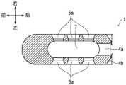
图5是示出将脊椎用植入体在图4的A-A线处切断的情况下的切断面的图。FIG. 5 is a view showing a cut surface of the spinal implant when cut along the line A-A in FIG. 4 .
图6是脊椎用植入体的保持器具的立体图。Fig. 6 is a perspective view of a holder of a spinal implant.
图7是示出将脊椎用植入体与保持器具连接后的状态的图。FIG. 7 is a diagram showing a state in which the spinal implant and the holder are connected.
具体实施方式Detailed ways
以下,参照附图对本发明的实施方式进行说明。Hereinafter, embodiments of the present invention will be described with reference to the drawings.
以往,对于插入体内的脊椎用植入体,没有特别提到将涂层所含的抗菌金属剂减少。然而,对于插入体内的脊椎用植入体,在进行含有抗菌金属剂的涂覆的情况下,有时希望在各种面上减少抗菌金属剂。Conventionally, there has been no particular mention of reducing the antimicrobial metal agent contained in the coating layer for a spinal implant to be inserted into the body. However, when the vertebral implant to be inserted into the body is coated with an antibacterial metal agent, it may be desirable to reduce the antibacterial metal agent on various surfaces.
于是,在本发明的一方案中,能够在形成有具有抗菌金属剂的涂层的脊椎用植入体中减少抗菌金属剂。具体情况以下说明。Thus, in one aspect of the present invention, the antibacterial metal agent can be reduced in the spinal implant in which the coating layer having the antibacterial metal agent is formed. The specific situation is explained below.
〔实施方式1〕[Embodiment 1]
以下,对本发明的一实施方式详细地进行说明。本实施方式的脊椎用植入体为了代替椎间盘或修补椎间盘,而插入相邻的椎骨间,并用于对脊柱构造的高度进行置换、矫正或修复。需要说明的是,插入相邻的椎骨间的脊椎用植入体例如也被称为椎体间间隔件、椎体间段、椎体间笼等。Hereinafter, one embodiment of the present invention will be described in detail. The vertebral implant of the present embodiment is inserted between adjacent vertebrae in order to replace or repair an intervertebral disc, and is used to replace, correct, or repair the height of a spinal structure. In addition, the vertebral implant inserted between adjacent vertebrae is also called, for example, an interbody spacer, an interbody segment, an interbody cage, or the like.
〔使用方式〕[How to use]
首先,参照图1对脊椎用植入体1的使用方式进行说明。图1是示出脊椎用植入体1的使用方式的一例的图。需要说明的是,为了便于说明,以下,将记载为前的箭头所表示的方向称为前侧或前方。另外,将记载为后的箭头所表示的方向称为后侧或后方。另外,将记载为上的箭头所表示的方向称为上侧或上方。另外,将记载为下的箭头所表示的方向称为下侧或下方。另外,将记载为右的箭头所表示的方向称为右侧。另外,将记载为左的箭头所表示的方向称为左侧。另外,图1中的前侧为人体的腹部侧,图1中的后侧为人体的脊背侧。First, the usage of the
本实施方式的脊椎用植入体1在作为椎间盘疝等的手术中的椎体间固定术之一的PLIF(Posterior Lumbar Interbody Fusion、后路腰椎椎体间融合术)等中使用。在该PLIF中,在去除压迫神经的骨骼而除压后,将棘突以及椎间关节切除或局部地切除,并摘除椎间盘以及软骨终板。然后,在相邻的椎骨50之间插入脊椎用植入体1,以修补该摘除了椎间盘的部分。The
脊椎用植入体1在由具有形成为棒状的杆部的保持器具100(参照图6)保持的状态下,从后方、即人体的前后方向上的脊背侧向椎骨间插入。通常,如图1所示,脊椎用植入体1向相邻的两个椎骨50之间以沿左右方向排列的方式插入两个。然后,以跨及被插入了脊椎用植入体1的两个椎骨50的方式架设金属制的杆(未图示)并固定于各椎骨50,从而两个椎骨50被相互固定。The
需要说明的是,本实施方式的脊椎用植入体1并不限于PLIF,也能够在其他手术方式、例如TLIF(Transforaminal Lumbar Interbody Fusion、经椎间孔腰椎椎体间融合术)等中使用。在该情况下,脊椎用植入体1仅从椎骨间的左右方向的任一侧插入。It should be noted that the
〔脊椎用植入体1的结构〕[Structure of Spine Implant 1]
接着,参照图2~图5对脊椎用植入体1的结构进行说明。图2~图5是示出脊椎用植入体1的结构的图,图2是脊椎用植入体1的立体图,图3是脊椎用植入体1的俯视图,图4是脊椎用植入体1的侧视图,图5是示出在图4的A-A所示的线处切断时的切断面的图。Next, the structure of the
如图2所示,本实施方式的脊椎用植入体1由沿前后方向延伸的大致长方体形状的基体2形成,并包括前表面3、后表面4、右侧面5、左侧面6、上表面8以及下表面9。并且,从上表面8到下表面9设置有从上表面8以及下表面9观察时的形状为椭圆的空腔部7,并且在右侧面5以及左侧面6设置有一个或多个孔部5a以及孔部6a。从右侧面5以及左侧面6观察时的多个孔部5a以及孔部6a的形状为圆形。As shown in FIG. 2 , the
需要说明的是,脊椎用植入体1并不限定于大致长方体形状,例如也可以为大致立方体形状。另外,从空腔部7的上表面8以及下表面9观察时的形状并不限定于椭圆,例如也可以为圆或四边形。另外,从右侧面5以及左侧面6观察到的多个孔部5a以及孔部6a的形状并不限定于圆形,例如也可以为四边形。It should be noted that the
另外,空腔部7的开口面(椭圆)的面积比侧面的孔部5a、6a的开口面(大致圆)的面积大。空腔部7也可以设置于基体2的靠后表面4处。即,从空腔部7到前表面3的距离也可以比从空腔部7到后表面4的距离小。In addition, the area of the opening surface (ellipse) of the
另外,侧面的孔部5a、6a也可以设置于基体2的靠后表面4处。即,从侧面的孔部5a、6a到前表面3的距离也可以比从侧面的孔部5a、6a到后表面4的距离小。另外,侧面的孔部5a、6a贯通至空腔部7,右侧面5或左侧面6侧的开口面的面积比空腔部7的内表面侧的开口面的面积大。另外,侧面的孔部5a、6a也可以成为锥形状。In addition, the
并且,在后表面4设置有螺孔4a(螺纹牙未图示)以及凹部4b。凹部4b设置为在后表面4的上下方向中央附近,从后表面4到右侧面5或左侧面6形成槽(缺口)。Moreover, the
在此,在本说明书中,例如将脊椎用植入体1的上下方向设为第一方向,空腔部7能够称为将基体2在第一方向上贯通的第一贯通部,脊椎用植入体1可以具备将基体2在第一方向上贯通的第一贯通部。Here, in this specification, for example, the vertical direction of the
另外,将脊椎用植入体1的左右方向设为第二方向,在左右方向上将基体2贯通的孔部5a、6a能够称为将基体2在与第一方向相交的第二方向上贯通的第二贯通部。并且,脊椎用植入体1可以具备将基体2在与第一方向相交的第二方向上贯通的第二贯通部。In addition, the left-right direction of the
在本实施方式中,基体2能够使用金属、陶瓷或塑料。作为金属,能够使用不锈钢合金、钴-铬合金、钛、钛合金等。作为钛合金,能够使用添加有铝、锡、锆、钼、镍、钯、钽、铌、钒、铂等中的至少一种的合金。另外,作为陶瓷,例如能够使用氧化铝、氧化锆、氧化铝-氧化锆复合陶瓷等。另外,作为塑料,例如能够使用聚乙烯、氟系树脂、环氧树脂、聚醚醚酮(PEEK)树脂、酚醛树脂等。In this embodiment, metal, ceramic or plastic can be used for the
前表面3形成为在前后方向上稍厚的壁状,中央部朝向前方(前端)鼓出而形成凸曲面。另外,前表面3以趋向前端而宽度变小的方式形成为锥形状。通过这样的形状,由于将前表面3形成为锥形状,从而在将脊椎用植入体1向椎骨间插入的情况下能够使插入容易。The
后表面4由平坦面形成。如图2所示,在后表面4的中央部分形成有在前后方向上从后表面4贯通至空腔部7的螺孔4a。该螺孔4a与在用于保持脊椎用植入体1的保持器具100的杆部前端形成的螺纹部101螺合。即,保持器具100作为一实施例也具有作为卡合器具的功能,螺纹部101也可以能够与具有作为卡合部的功能的螺孔4a卡合。The
另外,如图2等所示,在后表面4的上下方向的中央部分形成有凹部4b。保持器具100的杆部前端与该凹部4b抵接(参照图7)。需要说明的是,只要螺纹部101能够螺合,则螺孔4a也可以不贯通。另外,保持器具100的螺纹部101能够与杆部前端独立地进行旋转。通过仅使螺纹部101旋转,能够在保持器具100的杆部前端抵接于凹部4b的状态下相对于脊椎用植入体1拆装保持器具100。Moreover, as shown in FIG. 2 etc., the recessed
需要说明的是,脊椎用植入体1也可以不必借助螺孔4a而保持于保持器具100。例如,保持器具100也可以具有能够把持脊椎用植入体1的机构,且通过把持而保持脊椎用植入体1。In addition, the
另外,基体2形成为从前表面3到后表面4而缩小,换言之,形成为与前后方向垂直的面的截面积(由外缘包围的区域的面积)从后表面4朝向前表面3而变大。并且,随着从前表面3向后表面4前进,基体2的左右方向的宽度的变化量比上下方向的高度的变化量小。需要说明的是,在本实施方式中,更具体而言,也可以是,在比较后表面4以及前表面3时,沿着左右方向的长度的最大值为一定,并且沿着上下方向的长度的最大值变大。通过设为这样的形状,能够适合人体的椎体的形状。In addition, the
右侧面5以及左侧面6分别形成为沿前后方向延伸,并设置为在左右方向上对置。如图2所示,在右侧面5以及左侧面6的中央部分分别形成有在左右方向上贯通的孔部5a、6a。该孔部5a、6a用于促进插入并固定于椎骨间的状态下的脊椎用植入体1附近的血流。The
如图2、图3、图5所示,在脊椎用植入体1形成有从上表面8至下表面9在上下方向上贯通的空腔部7。在该空腔部7填充骨形成材料。As shown in FIGS. 2 , 3 , and 5 , a
如图2至图4所示,在上表面8形成有从该上表面8向上方突出并且在该上表面8的面内沿左右方向延伸的多个突条齿部10。同样地,在下表面9形成有从该下表面9向下方突出并且在该下表面9的面内沿左右方向延伸的多个突条齿部10。即,上述多个突条齿部10设置为从各面8、9突出的齿部。As shown in FIGS. 2 to 4 , the upper surface 8 has a plurality of protruding
需要说明的是,在该情况下,如上所述,“基体2形成为从前表面3到后表面4而缩小”是指突条齿部10的顶点的沿着上下方向的顶点高度趋向后方而变小。In this case, as described above, “the
另外,配置于上表面8的多个突条齿部10以及配置于下表面9的多个突条齿部10也可以处于分别相互在上下方向上对应的位置。即,配置于下表面9的某一个突条齿部10也可以位于配置于上表面8的某一个突条齿部10的下方向。In addition, the plurality of protruding
突条齿部10形成为前方向的倾斜(斜率)比后方向的倾斜(斜率)平缓(小)。在脊椎用植入体1的上表面8以及下表面9与椎骨50接触的情况下,使脊椎用植入体1容易向前方移动,并且难以使向后方移动。The protruding
这样,通过具备突条齿部10,能够抑制脊椎用植入体1的位置偏移,并且也能够抑制退出(back out)(后述)。In this way, by providing the protruding
另外,前表面3的上下方向的高度比突条齿部10部分的上下方向的高度小,后表面4存在于比将突条齿部10的顶点连结的假想线的延长线靠内侧处。The vertical height of the
另外,将多个突条齿部10的顶点连结的假想线也可以为曲线。另外,在将多个突条齿部10的顶点连结的假想线为曲线的情况下,曲线(假想曲线)的顶点也可以位于前表面3侧。即,假想曲线的顶点与前表面3的距离也可以比假想曲线的顶点与后表面4的距离小。In addition, an imaginary line connecting the vertices of the plurality of protruding
并且,在本实施方式的脊椎用植入体1中,没有在脊椎用植入体1的整体配置包含磷酸钙系材料和抗菌剂的覆膜,而包括配置有覆膜的第一区域与从覆膜露出的第二区域。In addition, in the
配置有包含磷酸钙系材料和抗菌剂的覆膜的第一区域与从覆膜露出的第二区域的识别能够通过各区域的表面的元素分析来进行。元素分析的方法例如能够通过由作为通常的扫描电子显微镜(SEM)的附属装置的能量分散型X射线分析(EDX)装置进行的表面元素的映射来实施。另外,也可以使用X射线光电子分光法、俄歇电子分光法、二次离子质量分析法等表面分析法。另外,也可以对将各区域的表面机械削掉而得到的试料进行化学分析,来确认元素。在第一区域的表面,检测出磷、钙、抗菌成分等。在第二区域的表面,检测出构成基材的元素,检测不出磷、钙、抗菌成分等或者为噪声水平以下。The identification of the first region where the coating containing the calcium phosphate-based material and the antibacterial agent is arranged and the second region exposed from the coating can be performed by elemental analysis of the surface of each region. The method of elemental analysis can be implemented by, for example, mapping of surface elements by an energy dispersive X-ray analysis (EDX) apparatus which is an accessory apparatus of a general scanning electron microscope (SEM). In addition, surface analysis methods such as X-ray photoelectron spectroscopy, Auger electron spectroscopy, and secondary ion mass spectrometry can also be used. In addition, it is also possible to perform chemical analysis on a sample obtained by mechanically chipping the surface of each region to confirm the element. On the surface of the first region, phosphorus, calcium, antibacterial components, and the like were detected. On the surface of the second region, elements constituting the base material were detected, and phosphorus, calcium, antibacterial components, etc. were not detected, or the noise level or less.
例如,在脊椎用植入体1的表面中的螺孔4a的区域(第二区域)未配置覆膜,仅在螺孔4a以外的区域(第一区域)配置覆膜。在该情况下,螺孔4a的区域直接露出脊椎用植入体1的基体表面。第二区域可以为螺孔4a整体,也可以为螺孔4a的一部分。另外,第二区域并不限定于螺孔4a,也可以是脊椎用植入体1的其他部分。需要说明的是,从覆膜露出的基体表面的部分(第二区域)从覆膜露出即可,也可以形成有与覆膜不同的膜、层。For example, the coating is not arranged in the region (second region) of the
由此,脊椎用植入体1能够在享有由配置覆膜带来的优点的同时,降低覆膜剥离而带入体内的风险。As a result, the
另外,关于脊椎用植入体1的覆膜,上表面8与右侧面5或左侧面6之间的边界部、或者下表面9与右侧面5或左侧面6之间的边界部的膜厚也可以比其他区域的膜厚厚。即,能够将基体的角部的覆膜形成得较厚。In addition, regarding the coating of the
另外,关于脊椎用植入体1的空腔部7的覆膜,空腔部7的开口的边缘的膜厚也可以比空腔部7的内表面的膜厚厚。另外,也可以以从空腔部7的开口趋向内侧而膜厚变薄的方式形成有覆膜。In addition, regarding the coating of the
〔基体的准备〕[Preparation of the substrate]
对脊椎用植入体1的制造方法进行说明。首先,为了脊椎用植入体1的制造,而准备基体2。基体2例如能够通过对由金属材料构成的圆棒等块进行切削加工而形成。通过切削加工,能够准备具备前表面3、后表面4、上表面8、下表面9、右侧面5、左侧面6、空腔部7以及孔部5a、6a等各构成要素的基体。即,在成为脊椎用植入体1的基体中,设置在上下方向上贯通的空腔部7,在左右侧面设置孔部5a、6a,在后表面设置螺孔4a(形成卡合部的工序、孔形成工序)。需要说明的是,基体2也可以通过对陶瓷或树脂的块进行切削而形成,也可以通过与切削加工不同的方法而成形。The manufacturing method of the
〔覆膜方法〕[Lamination method]
接着,对脊椎用植入体1的覆膜方法进行说明。本实施方式的脊椎用植入体1通过向基体上喷镀包含磷酸钙系材料以及抗菌剂的材料而形成覆膜。抗菌剂例如为银,喷镀覆膜中的银浓度例如为0.05重量%~3.00重量%。作为磷酸钙系材料,能够使用从由羟基磷灰石、α-第三磷酸钙、β-第三磷酸钙以及第四磷酸钙构成的组中选择的一种或两种以上的混合物。Next, the coating method of the
作为用于形成包含磷酸钙系材料的喷镀覆膜的喷镀法,能够举出火焰喷镀法、高速火焰喷镀法、等离子体喷镀法以及冷喷涂法。例如,在火焰喷镀法中,将氧与可燃性气体的气体火焰作为热源使喷镀材料成为熔融或接近熔融的状态向母材的表面吹送而形成覆膜。在通常的火焰喷镀法中,喷镀温度为约2700℃,喷镀速度为0.6马赫。作为喷镀条件,例如能够向氧气50psi、乙炔气体43psi的气体火焰炬中利用100psi的干燥空气导入喷镀粉末,并以喷镀距离60~100mm进行喷镀。As a thermal spraying method for forming the thermal spraying film containing a calcium phosphate type material, a flame spraying method, a high-speed flame spraying method, a plasma spraying method, and a cold spraying method are mentioned. For example, in the flame spraying method, a gas flame of oxygen and a combustible gas is used as a heat source to blow a thermal spray material in a molten or nearly molten state onto the surface of a base material to form a coating. In a normal flame spraying method, the spraying temperature is about 2700°C, and the spraying speed is Mach 0.6. As the thermal spraying conditions, for example, the thermal spraying powder can be introduced into a gas torch of 50 psi of oxygen gas and 43 psi of acetylene gas with dry air of 100 psi, and thermal spraying can be performed at a thermal spraying distance of 60 to 100 mm.
喷镀覆膜的厚度为5~100μm,优选为20~40μm。这是因为,若为5μm以上,则能够覆盖喷镀部位的整个区域,另外,若为100μm以下,则不会出现由于喷镀时的残留应力而使覆膜的紧贴强度下降的情况。The thickness of the thermal spray coating is 5 to 100 μm, preferably 20 to 40 μm. This is because if it is 5 μm or more, the entire area of the thermally sprayed site can be covered, and if it is 100 μm or less, the adhesion strength of the coating does not decrease due to residual stress during thermal spraying.
在本实施方式中,包含抗菌材料的磷酸钙系材料的喷镀覆膜通过将覆膜原料的粉末在熔融(或半熔融)状态下向母材(基体)吹送并冷却、固化、堆积而形成。因此,也可以将喷镀覆膜称为喷镀层或涂层。In this embodiment, the thermal spray coating of the calcium phosphate-based material containing the antibacterial material is formed by blowing the powder of the coating raw material in a molten (or semi-molten) state to the base material (substrate), cooling, solidifying, and depositing . Therefore, the thermal spray coating may also be referred to as a thermal spray layer or a coating layer.
也可以对形成的喷镀覆膜进行热处理。这是因为,在该情况下,磷酸钙系材料的结晶度增加而使覆膜的稳定性提高。热处理在10-2Pa以下的减压下在400~1000℃的温度范围内进行0.5~7小时。优选的是550~850℃的温度范围且为1~5小时。The formed thermal spray coating may also be subjected to heat treatment. This is because, in this case, the crystallinity of the calcium phosphate-based material increases to improve the stability of the coating. The heat treatment is performed in a temperature range of 400 to 1000° C. for 0.5 to 7 hours under a reduced pressure of 10−2 Pa or less. The temperature range of 550-850 degreeC and 1-5 hours are preferable.
另外,也可以在热处理后对喷镀覆膜进行水合处理。通过进行水合处理,能够从氧磷灰石变换为羟基磷灰石,能够使银离子的溶出性稳定化。水合处理是对物质附加水分子的工序,例如能够通过在60~100℃的水中浸渍10~60分钟而进行。In addition, a hydration treatment may be performed on the thermal spray coating after the heat treatment. By performing the hydration treatment, it is possible to convert from oxyapatite to hydroxyapatite, and to stabilize the dissolution properties of silver ions. The hydration treatment is a step of adding water molecules to a substance, and can be performed, for example, by immersion in water at 60 to 100° C. for 10 to 60 minutes.
喷镀覆膜中的银浓度能够通过使与成为喷镀材料的磷酸钙系材料调配的银原料的量变化而进行调整。喷镀覆膜中的银浓度为0.05重量%~3.00重量%,优选为0.05重量%~2.50重量%,更优选为0.05重量%~1.00重量%,进一步优选为0.1重量%~1.00重量%。这是因为,若为0.05重量%以上,则抗菌性变得充分。另外,若为3.00重量%以下,则能够抑制对生物体组织的负担。The silver concentration in the thermal spray coating can be adjusted by changing the amount of the silver raw material to be prepared with the calcium phosphate-based material serving as the thermal spray material. The silver concentration in the thermal spray coating is 0.05 to 3.00% by weight, preferably 0.05 to 2.50% by weight, more preferably 0.05 to 1.00% by weight, still more preferably 0.1 to 1.00% by weight. This is because antibacterial properties become sufficient when it is 0.05% by weight or more. Moreover, if it is 3.00 weight% or less, the burden on living tissue can be suppressed.
脊椎用植入体1的覆膜工序如以下那样。在基体局部地形成包含磷酸钙系材料和抗菌剂的覆膜(覆膜形成工序)。需要说明的是,在基体局部地形成有包含磷酸钙系材料和抗菌剂的覆膜的区域为第一区域,未形成覆膜的基体的区域为第二区域。在该覆膜形成工序中,在螺孔4a插入有覆盖形成工序用的螺钉的状态下形成覆膜,之后取出螺钉。由此,能够除了螺孔4a以外而形成覆膜。在将第二区域配置为螺孔4a整体时,将螺孔4a用覆盖形成工序用的螺钉全部填埋即可。覆盖形成工序用的螺钉例如配置为贯通螺孔4a。需要说明的是,在进行粗面化的情况下,在形成覆膜前进行粗面化即可(粗面化工序)。The coating process of the
覆膜的形成方法并不限于火焰喷镀、高速火焰喷镀、等离子体喷镀等喷镀法。也可以选择溅射、离子镀、离子束蒸镀、离子搅拌法等物理蒸镀法或者溶胶凝胶法等湿式涂覆法。The coating film formation method is not limited to thermal spraying methods such as flame spraying, high-speed flame spraying, and plasma spraying. Physical vapor deposition methods such as sputtering, ion plating, ion beam vapor deposition, and ion stirring methods, or wet coating methods such as sol-gel methods can also be selected.
另外,覆膜可以通过上述的方法直接配置于基体2,也可以如以下那样经由中间层而配置。即,也可以通过在涂布、镀敷、喷镀、蒸镀等方法在基体表面形成覆膜,并将该覆膜作为中间层进一步形成上述的磷酸钙系材料的覆膜。另外,作为中间层的形成方法,也可以使用增材制造(additive manufacturing)的方法。In addition, the coating film may be directly disposed on the
作为中间层,也可以是金属、高分子或陶瓷。例如,也可以在将PEEK树脂作为基体并将钛金属的中间层形成于基体的期望的表面后,将包含磷酸钙系材料和抗菌剂的覆膜形成于中间层的表面上。As the intermediate layer, metal, polymer, or ceramic may also be used. For example, after forming an intermediate layer of titanium metal on a desired surface of the substrate using PEEK resin as a substrate, a coating film containing a calcium phosphate-based material and an antibacterial agent may be formed on the surface of the intermediate layer.
〔向椎骨间插入的插入方法〕[Insertion method for intervertebral insertion]
接着,对将本实施方式的脊椎用植入体1向椎骨间插入时的步骤进行说明。Next, the procedure at the time of inserting the
首先,手术者在将脊椎用植入体1向椎骨间插入时,将脊椎用植入体1安装于用于保持脊椎用植入体1的保持器具100。具体而言,在将保持器具100的杆部夹入脊椎用植入体1的凹部4b的状态下,将保持器具100的螺纹部与脊椎用植入体1的螺孔4a螺合。由此,脊椎用植入体1被相对于保持器具100定位,脊椎用植入体1被保持。需要说明的是,在脊椎用植入体1的空腔部7填充骨形成材料。First, when inserting the
接着,手术者将脊椎用植入体1向椎骨间插入。具体而言,手术者相对于被去除了压迫神经的骨骼以及椎间盘等的椎骨间,将脊椎用植入体1的前表面3侧从人体的脊背侧插入。然后,在将脊椎用植入体1配置于相邻的椎骨50间的左右一侧(例如右侧)后,将保持器具100从脊椎用植入体1拆下,从而将脊椎用植入体1设置于椎骨间的右侧的部分。在脊椎用植入体1的设置位置比在术前设想的位置浅的情况下,使用打入器具(冲击器)将脊椎用植入体1打入,而调整设置位置。同样地,手术者将脊椎用植入体1设置于相邻的椎骨间的左侧的部分。Next, the operator inserts the
然后,手术者在相邻的椎骨间架设金属制的杆(省略图示),并将该杆固定于各椎骨50。由此,能够将相邻的椎骨50相互固定。在手术后,通过将填充于空腔部7的骨形成材料与上下的椎骨50骨融合,从而将相邻的椎骨50牢固地固定。Then, the operator installs a metal rod (not shown) between the adjacent vertebrae, and fixes the rod to each
然而,通常在将脊椎笼固定于椎骨间的初始状态、或填充于空腔部的骨形成材料未与椎骨充分地骨融合的状态等下,有时产生退出的问题。退出是指设置于椎骨间的规定位置的脊椎用植入体1向患者的脊背侧(后方)移动而偏移。However, in general, in the initial state where the spine cage is fixed between the vertebrae, or in the state where the bone-forming material filled in the cavity portion is not sufficiently fused with the vertebrae, a problem of withdrawal sometimes occurs. The withdrawal means that the
在本实施方式的脊椎用植入体1中,对于设置于上表面8以及下表面9的突条齿部10的倾斜而言,后表面比前表面陡峭。由此,能够使脊椎用植入体1难以向后方移动,能够抑制脊椎用植入体1退出。In the
〔粗面化〕[Roughening]
也可以将脊椎用植入体1的表面的一部分粗面化,而具有粗面部。例如,也可以将脊椎用植入体1的上表面8以及下表面9粗面化。粗面化例如能够通过使用喷镀以及喷丸处理中的至少一个来进行。作为喷镀材料,能够使用作为基体2的材料而例示的材料。作为喷丸处理,可以举出喷砂等。另外,也能够通过使用3D打印机等进行在脊椎用植入体1的表面形成多孔质构造等的处理而进行粗面化。通过将上表面8以及下表面9粗面化,从而被粗面了的部分与脊椎接触,能够使脊椎用植入体1与脊椎的固接性提高。A part of the surface of the
需要说明的是,对于粗面的形成而言,在形成覆膜前进行粗面化即可。另外,之后在所形成的粗面上形成覆膜即可。In addition, about formation of a rough surface, what is necessary is just to roughen it before forming a coating film. In addition, what is necessary is just to form a coating film on the formed rough surface after that.
粗面的形成通过将基体的各面粗面化来进行即可。具体而言,能够对上表面8、下表面9从第一方向进行粗面化处理而形成粗面,并对右侧面5、左侧面6从第二方向进行粗面化处理而形成粗面。另外,之后,能够对前表面3从与第一方向以及第二方向相交的第三方向(前后方向)进行粗面化处理而形成粗面。The formation of the rough surface may be performed by roughening each surface of the substrate. Specifically, the upper surface 8 and the
需要说明的是,根据前表面3的形状,有时通过对上表面8、下表面9、右侧面5以及左侧面6进行的粗面化处理而在前表面3上也形成足够粗糙的粗面。在该情况下,也可以省略对前表面3的粗面化处理。It should be noted that, depending on the shape of the
另外,也可以对空腔部7以及孔部5a、6a各自的内表面进行粗面的形成。In addition, rough surface formation may be performed on the inner surface of each of the
需要说明的是,也可以根据空腔部7、孔部5a、6a的形状以及喷镀或喷砂的方向,在对覆膜的外表面(上表面8、下表面9、右侧面5以及左侧面6)进行喷镀等的同时,向空腔部7、孔部5a、6a的内表面进行喷镀,而形成包括第一区域以及第二区域的覆膜。It should be noted that, depending on the shape of the
〔变形例〕[Variation]
另外,在本实施方式中,通过利用螺纹将保持器具100与脊椎用植入体1螺合,而利用保持器具100保持脊椎用植入体1,但保持器具100对脊椎用植入体1的保持并不限于螺纹。In addition, in the present embodiment, the
例如,也可以通过在脊椎用植入体1的基体2设置包括凹部或凸部的卡止机构,并使卡止保持器具100的一部分嵌合于该卡止机构而卡止,从而保持脊椎用植入体1。具体而言,也可以为如下机构:在基体设置内部的直径比开口部的直径大的孔,在保持器具的前端设置使外径可变的机构,在缩小了保持器具前端的外径的状态下将其插入基体的孔,然后在孔的内部增大外径而进行卡止等。即,也可以是,保持器具100也具有作为卡合器具的功能,与保持器具卡合的孔(卡合部)具有将保持器具100与基体2卡止的卡止机构。需要说明的是,也可以利用夹持基体的一部分的保持器具将脊椎用植入体卡止而进行保持。For example, the
另外,在本实施方式中,将从覆膜露出的第二区域设为螺孔4a的区域而进行了说明。在此,可以将螺孔4a的沿着深度方向的整个区域设为第二区域,但也可以仅将一部分的区域设为第二区域。但是,优选将插入保持器具100的一侧的区域设为第二区域。另外,第二区域并不限定于螺孔4a的区域,也可以是上述的卡止机构、卡合部的区域。另外,并不限于这些区域,也可以将在利用保持器具100保持脊椎用植入体1时与保持器具100的一部分相接的区域、或者与保持器具100的一部分滑动的区域设为第二区域。优选将以上说明的区域以外的部分设为配置有覆膜的第一区域,但也可以在以上说明的区域以外也设置从覆膜露出的第二区域。In addition, in this Embodiment, the 2nd area|region exposed from the coating film was demonstrated as the area|region of the
另外,在本实施方式中,作为本发明的脊椎用植入体,例示了插入相邻的椎骨间的脊椎用植入体1。然而,本发明的脊椎用植入体并不限于上述脊椎用植入体1。例如,用于在将脊椎用植入体1插入到椎骨间的状态下进行固定的脊椎杆(用于将脊椎固定为一定的形状的构件)、脊椎螺杆(为了将脊椎杆固定于脊椎而拧入椎骨的构件)等也包括在本发明的脊椎用植入体中。在该情况下,优选从覆膜露出的第二区域设定为构件彼此(例如,脊椎杆与脊椎螺杆)相接、或者滑动的区域。In addition, in the present embodiment, as the spinal implant of the present invention, the
〔实施方式2〕[Embodiment 2]
以下对本发明的其他实施方式进行说明。需要说明的是,为了便于说明,对于具有与在上述实施方式中说明了的构件相同的功能的构件,标记相同的附图标记,且不重复其说明。即,关于在本实施方式中未言及的结构,与上述的实施方式1中的结构相同。Other embodiments of the present invention will be described below. In addition, for convenience of description, the same reference numerals are attached to the members which have the same function as the member demonstrated in the said embodiment, and the description is not repeated. That is, the structure not mentioned in this embodiment is the same as the structure in
〔脊椎用植入体1的结构〕[Structure of Spine Implant 1]
在本实施方式的脊椎用植入体1中,可以没有在脊椎用植入体1的整体配置包含磷酸钙系材料和抗菌剂的覆膜,而包括配置有覆膜的第一区域、覆膜的膜厚比第一区域小的第六区域。In the
在本实施方式中,例如,脊椎用植入体1的前表面3、后表面4的一部分(除了螺孔4a、凹部4b的部分)、上表面5、下表面9、右侧面5以及左侧面6是配置有覆膜的第一区域。另外,孔部5a、6a的内表面、空腔部7的内表面以及凹部4b是配置有膜厚比第一区域小的覆膜的第六区域。In the present embodiment, for example, the
这样,第一区域可以是基体2的外周面,第六区域可以是空腔部7的内表面以及孔部5a、6a的内表面。由此,脊椎用植入体1能够在享有由配置有覆膜带来的优点的同时,与脊椎用植入体1整体被覆膜涂覆的情况相比能够减少覆膜的总量。In this way, the first region may be the outer peripheral surface of the
另外,通过覆膜具有膜厚比第一区域小的第六区域,从而与第一区域的覆膜相比能够容易地形成第六区域的覆膜,进而能够使脊椎用植入体1的制造效率提高。In addition, since the coating has the sixth region whose film thickness is smaller than that of the first region, the coating of the sixth region can be formed more easily than the coating of the first region, and the production of the
另外,脊椎用植入体1还包括覆膜的膜厚比第六区域小、或者未被覆膜的(从覆膜露出的)第三区域。需要说明的是,第三区域相当于上述的实施方式1的第二区域。在本实施方式中,螺孔4a为未配置覆膜的第三区域。在该情况下,螺孔4a的区域直接露出脊椎用植入体1的基体表面。第三区域可以是螺孔4a整体,也可以是螺孔4a的一部分。另外,第三区域并不限定于螺孔4a,也可以是脊椎用植入体1的其他部分。需要说明的是,从覆膜露出的基体表面的部分(第三区域)从覆膜露出即可,也可以形成有与覆膜不同的膜、层。In addition, the
〔覆膜方法〕[Lamination method]
脊椎用植入体1的覆膜工序如以下那样。覆膜以膜厚不同的方式形成(覆膜形成工序)。由此,关于覆膜,能够形成膜厚不同的第一区域以及第六区域。覆膜的形成能够通过对基体2的各面进行喷镀覆膜而形成。在通过喷镀而形成的情况下,基体2上的覆膜的厚度例如能够通过调整喷镀时间、喷镀方向、喷镀材料的结构、喷镀温度等喷镀条件而改变。例如,在增大基体2的覆膜的厚度的情况下,能够通过延长喷镀时间而实现,在减小基体2的覆盖的厚度的情况下,能够通过缩短喷镀时间而实现。The coating process of the
具体而言,能够对上表面8、下表面9从第一方向进行喷镀而形成覆膜,并对右侧面5、左侧面6从第二方向进行喷镀而形成覆膜。另外,之后,能够对前表面3从与第一方向以及第二方向相交的第三方向(前后方向)进行喷镀而形成覆膜。这样,能够对基体2的各面形成覆膜的第一区域。Specifically, the upper surface 8 and the
需要说明的是,根据前表面3的形状,有时通过对上表面8、下表面9、右侧面5以及左侧面6进行的喷镀而在前表面3上也形成足够膜厚的覆膜。在该情况下,也可以省略对前表面3的喷镀。It should be noted that, depending on the shape of the
另外,对空腔部7以及孔部5a、6a各自的内表面进行覆膜的形成。对于对空腔部7以及孔部5a、6a的喷镀而言,通过与形成覆膜的第一区域的情况相比缩短照射时间,能够形成膜厚比第一区域小的第六区域的覆膜。另外,覆膜的第六区域的形成例如也可以通过与形成第一区域的情况相比降低喷镀的材料的量而形成。In addition, a film is formed on the inner surfaces of the
需要说明的是,也可以根据空腔部7、孔部5a、6a的形状以及喷镀方向,在对覆膜的外表面(上表面8、下表面9、右侧面5以及左侧面6)进行喷镀的同时,向空腔部7、孔部5a、6a的内表面进行喷镀而形成包括第一区域以及第六区域的覆膜。即,通过设想基体2的形状与喷镀材料的回绕量来对基体2进行喷镀,能够形成第一区域的膜厚以及第六区域的膜厚。It should be noted that, depending on the shape of the
另外,对后表面4的凹部4b的内表面进行覆膜的形成。对于对凹部4b的喷镀而言,通过与形成覆膜的2区域的情况相比缩短照射时间,能够形成膜厚比第六区域小的第三区域的覆膜。另外,覆膜的第三区域的形成例如也可以通过与形成第六区域的情况相比降低喷镀的材料的量而形成。需要说明的是,覆膜的第三区域也可以通过喷镀条件而与第一区域以及第六区域同时形成。另外,关于除了凹部4b的后表面4,可以是覆膜的第一区域或第六区域。In addition, film formation is performed on the inner surface of the recessed
需要说明的是,在覆膜形成工序中,在螺孔4a插入有覆盖形成工序用的螺钉的状态下形成覆膜,之后取出螺钉。由此,能够除了螺孔4a以外而形成覆膜。在将第六区域配置为螺孔4a整体时,将螺孔4a用覆盖形成工序用的螺钉全部填埋即可。覆盖形成工序用的螺钉例如配置为贯通螺孔4a。由此,也可以形成覆膜的第三区域。需要说明的是,在进行粗面化的情况下,在形成覆膜前进行粗面化即可(粗面化工序)。In addition, in the film forming step, the film is formed in a state in which the screw for the cover forming step is inserted into the
〔粗面化〕[Roughening]
粗面的形成通过将基体的各面粗面化而进行即可。具体而言,能够对上表面8、下表面9从第一方向进行粗面化处理而形成粗面,并对右侧面5、左侧面6从第二方向进行粗面化处理而形成粗面。另外,之后,能够对前表面3从与第一方向以及第二方向相交的第三方向(前后方向)进行粗面化处理而形成粗面。这样,能够对基体2的各面形成粗面的第四区域。The formation of the rough surface may be performed by roughening each surface of the base body. Specifically, the upper surface 8 and the
需要说明的是,根据前表面3的形状,有时通过对上表面8、下表面9、右侧面5以及左侧面6进行的粗面化处理而在前表面3上也形成足够粗糙的粗面。在该情况下,也可以省略对前表面3的粗面化处理。It should be noted that, depending on the shape of the
另外,对空腔部7以及孔部5a、6a各自的内表面进行粗面的形成。对空腔部7以及孔部5a、6a的粗面化处理通过与形成粗面的第四区域的情况相比缩短处理时间,能够形成粗糙度比第四区域小的第五区域的粗面。另外,粗面的第五区域的形成例如也可以通过与形成第四区域的情况相比降低喷镀的材料的量或喷砂的量而形成。In addition, rough surface formation is performed on the inner surfaces of the
需要说明的是,也可以根据空腔部7、孔部5a、6a的形状以及喷镀或喷砂的方向,在对覆膜的外表面(上表面8、下表面9、右侧面5以及左侧面6)进行喷镀等的同时,向空腔部7、孔部5a、6a的内表面进行喷镀而形成包括第一区域以及第六区域的覆膜。It should be noted that, depending on the shape of the
需要说明的是,前述的第一区域为脊椎用植入体1的前表面3、后表面4、上表面8、下表面9、右侧面5以及左侧面6,因此也可以与第四区域重叠。另外,第六区域为空腔部7的内表面以及孔部5a、6a的内表面,因此也可以与第五区域重叠。It should be noted that the aforementioned first region is the
〔变形例〕[Variation]
另外,在本实施方式中,将从覆膜露出的第三区域设为螺孔4a的区域而进行了说明。在此,可以将螺孔4a的沿着深度方向的整个区域设为第三区域,但也可以仅将一部分的区域设为第三区域。但是,优选将插入保持器具100的一侧的区域设为第三区域。另外,第三区域并不限定于螺孔4a的区域,也可以是上述的卡止机构、卡合部的区域。另外,并不限于这些区域,也可以将在利用保持器具100保持脊椎用植入体1时与保持器具100的一部分相接的区域、或者与保持器具100的一部分滑动的区域设为第三区域。优选以上说明的区域以外的部分设为配置有覆膜的第一区域或第六区域,但也可以在以上说明的区域以外也设置从覆膜露出的第三区域。In addition, in this embodiment, the 3rd area|region exposed from the coating film was demonstrated as the area|region of the
另外,在本实施方式中,将孔部5a、6a的内表面、空腔部7的内表面以及凹部4b设为第六区域,但凹部4b也可以是第一区域。另外,也可以将螺孔4a以外的不面向外部的面设为第六区域。In this embodiment, the inner surfaces of the
另外,在本实施方式中,作为本发明的脊椎用植入体,例示了插入相邻的椎骨间的脊椎用植入体1。然而,本发明的脊椎用植入体并不限于上述脊椎用植入体1。例如,用于在将脊椎用植入体1插入到椎骨间的状态下进行固定的脊椎杆(用于将脊椎固定为一定的形状的构件)、脊椎螺杆(为了将脊椎杆固定于脊椎而拧入椎骨的构件)等也包括在本发明的脊椎用植入体中。在该情况下,优选从覆膜露出的第三区域设定为构件彼此(例如,脊椎杆与脊椎螺杆)相接、或者滑动的区域。In addition, in the present embodiment, as the spinal implant of the present invention, the
本发明并不限定于上述的实施方式,能够在技术方案所示的范围内进行各种变更,将不同的实施方式分别公开的技术方案适当组合而得到的实施方式也包括在本发明的技术范围内。并且,通过将实施方式分别公开的技术方案组合,能够形成新的技术特征。The present invention is not limited to the above-described embodiments, and various modifications can be made within the scope indicated by the technical solutions, and embodiments obtained by appropriately combining technical solutions disclosed in different embodiments are also included in the technical scope of the present invention. Inside. Furthermore, new technical features can be formed by combining the technical solutions disclosed in the respective embodiments.
〔总结〕〔Summarize〕
本发明的一方案的脊椎用植入体具备:基体;以及覆膜,其配置于所述基体上,并包含磷酸钙系材料和抗菌剂,所述基体的表面具有配置有所述覆膜的第一区域以及从所述覆膜露出的第二区域。A spinal implant according to an aspect of the present invention includes: a base body; and a coating which is arranged on the base body and includes a calcium phosphate-based material and an antibacterial agent, and the surface of the base body has a coating on which the coating is arranged. a first region and a second region exposed from the cover film.
所述覆膜中的磷酸钙系材料具有提高骨传导性以及骨固定性的效果。所述覆膜中的抗菌剂具有降低细菌的附着以及增殖的效果。The calcium phosphate-based material in the coating has the effect of improving osteoconductivity and bone fixation. The antibacterial agent in the film has the effect of reducing the adhesion and proliferation of bacteria.
并且,根据所述的结构,能够保持所述基体的从覆膜露出的第二区域而在手术时等将脊椎用植入体插入体内,因此在脊椎用植入体的插入时以及保持器具的取出时,覆膜不易从保持部分剥落。因而,与覆盖基体的整面的情况相比,能够降低覆膜剥离而带入体内的风险。In addition, according to the above-described configuration, the vertebral implant can be inserted into the body during surgery or the like while maintaining the second region of the base body exposed from the coating. When taken out, the film is not easily peeled off from the holding portion. Therefore, compared with the case where the entire surface of the base body is covered, the risk of the coating film peeling off and being taken into the body can be reduced.
在本发明的一方案的脊椎用植入体中,也可以是,所述脊椎用植入体还具备配置于所述第二区域并能够与卡合器具卡合的卡合部。In the spinal implant according to one aspect of the present invention, the spinal implant may further include an engaging portion which is disposed in the second region and can be engaged with an engaging tool.
根据所述的结构,在第二区域具备能够与卡合器具卡合的卡合部,因此能够防止在卡合时覆膜剥落。According to the above-described configuration, since the second region is provided with the engaging portion capable of engaging with the engaging tool, it is possible to prevent the coating from peeling off during the engaging.
在本发明的一方案的脊椎用植入体中,也可以是,所述卡合部具有将所述卡合器具与所述基体卡止的包括凹部或凸部的卡止机构。In the vertebral implant according to an aspect of the present invention, the engaging portion may have a locking mechanism including a concave portion or a convex portion for locking the engaging tool and the base body.
根据所述的结构,能够不使用粘合剂、磁力等,而通过包括凹部或凸部的卡止机构将卡合器具与基体卡止。According to the above-described configuration, the engaging tool and the base body can be locked by the locking mechanism including the recessed portion or the convex portion without using an adhesive, magnetic force, or the like.
在本发明的一方案的脊椎用植入体中,也可以是,在所述卡合部具有螺孔。In the vertebral implant according to an aspect of the present invention, the engaging portion may have a screw hole.
根据所述的结构,通过使用螺孔,能够将脊椎用植入体容易地安装于保持器具,另外,也能够容易取出。According to the above-described configuration, by using the screw holes, the vertebral implant can be easily attached to the holder, and can also be easily removed.
在本发明的一方案的脊椎用植入体中,也可以是,所述基体具有被粗面化的粗面部,所述覆膜覆盖该粗面部的至少一部分。In the vertebral implant according to one aspect of the present invention, the base body may have a rough surface portion that is roughened, and the coating may cover at least a part of the rough surface portion.
根据所述的结构,通过使粗面部与脊椎接触,能够使脊椎用植入体与脊椎的固接性提高。According to the above-mentioned configuration, by bringing the rough surface portion into contact with the spine, the fixation between the spine implant and the spine can be improved.
在本发明的一方案的脊椎用植入体中,优选的是,所述覆膜直接配置于所述基体。In the vertebral implant according to one aspect of the present invention, it is preferable that the coating is directly arranged on the base.
根据所述的结构,脊椎用植入体的结构变得简单,因此能够抑制制造成本。According to the above-described structure, the structure of the spinal implant is simplified, so that the manufacturing cost can be suppressed.
本发明的一方案的脊椎用植入体的制造方法包括在基体局部地形成包含磷酸钙系材料和抗菌剂的覆膜的覆膜形成工序。The method for producing a spinal implant according to an aspect of the present invention includes a film forming step of locally forming a film containing a calcium phosphate-based material and an antibacterial agent on the base body.
在本发明的一方案的脊椎用植入体的制造方法中,也可以是,所述脊椎用植入体的制造方法包括在所述覆膜形成工序之前在所述基体形成能够与卡合器具卡合的卡合部的工序,在所述覆膜形成工序中,除了所述卡合部以外而形成所述覆膜。In the method for producing a spinal implant according to an aspect of the present invention, the method for producing a spinal implant may include forming an engaging tool on the base before the film forming step. In the step of engaging the engaging portion, in the coating film forming step, the coating is formed in addition to the engaging portion.
在本发明的一方案的脊椎用植入体的制造方法中,也可以是,所述脊椎用植入体的制造方法包括在所述覆膜形成工序之前在所述基体形成螺孔的孔形成工序,在所述覆膜形成工序中,在所述基体除了所述螺孔以外而形成所述覆膜。In the method for producing a spinal implant according to an aspect of the present invention, the method for producing a spinal implant may include forming a hole for forming a screw hole in the base body before the film forming step In the step of forming the coating film, the coating film is formed on the base body except for the screw hole.
在本发明的一方案的脊椎用植入体的制造方法中,也可以是,所述脊椎用植入体的制造方法包括在所述覆膜形成工序之前将所述基体的一部分粗面化而形成粗面部的粗面化工序,在所述覆膜形成工序中,以覆盖所述粗面部的至少一部分的方式形成覆膜。In the method for producing a spinal implant according to an aspect of the present invention, the method for producing a spinal implant may include roughening a part of the base body before the coating film forming step. In the roughening step of forming a rough surface, in the coating film forming step, a coating is formed so as to cover at least a part of the rough surface.
在本发明的一方案的脊椎用植入体的制造方法中,也可以是,在所述粗面化工序中,通过喷镀以及喷丸处理中的至少任一方而进行粗面化。In the method for producing a spinal implant according to an aspect of the present invention, in the roughening step, roughening may be performed by at least one of thermal spraying and shot peening.
本发明的一方案的脊椎用植入体具备:基体;以及覆膜,其配置于所述基体上,并包含磷酸钙系材料和抗菌剂,所述覆膜具有第一区域以及膜厚比所述第一区域小的第六区域。A spinal implant according to one aspect of the present invention includes: a base body; and a coating film which is disposed on the base body and contains a calcium phosphate-based material and an antibacterial agent, the coating film having a first region and a film thickness ratio determined by The sixth area is smaller than the first area.
所述覆膜中的磷酸钙系材料具有提高骨传导性以及骨固定性的效果。另外,所述覆膜中的抗菌剂具有降低细菌的附着以及增殖的效果。另一方面,抗菌金属剂也花费成本,因此优选尽可能少。并且,根据所述的结构,使覆膜的一部分的区域的膜厚比其他区域薄,因此与不减薄的情况相比,能够减少抗菌金属剂的总量。由此,例如能够实现成本的降低。The calcium phosphate-based material in the coating has the effect of improving osteoconductivity and bone fixation. In addition, the antibacterial agent in the film has the effect of reducing the adhesion and proliferation of bacteria. On the other hand, the antibacterial metal agent also costs, so it is preferable that it is as small as possible. Moreover, according to the said structure, since the film thickness of a part of area|region of a coating film is made thinner than other area|regions, it can reduce the total amount of an antimicrobial metal agent compared with the case where it is not thinned. Thereby, for example, cost reduction can be achieved.
在本发明的一方案的脊椎用植入体中,也可以是,所述脊椎用植入体还具备在第一方向上贯通所述基体的第一贯通部。In the vertebral implant according to one aspect of the present invention, the vertebral implant may further include a first penetration portion penetrating the base body in the first direction.
根据所述的结构,能够向第一贯通部填充骨形成材料,由此能够使脊椎用植入体与椎骨的接合容易。According to the above configuration, the bone-forming material can be filled in the first penetration portion, whereby the vertebral implant can be easily joined to the vertebrae.
在本发明的一方案的脊椎用植入体中,也可以是,所述第一区域位于所述基体的外周面,所述第六区域位于所述第一贯通部的内表面。In the spinal implant according to an aspect of the present invention, the first region may be located on the outer peripheral surface of the base body, and the sixth region may be located on the inner surface of the first penetration portion.
根据所述的结构,使第一贯通部的内表面的覆膜的膜厚比外周面的覆膜的膜厚小,因此能够维持与椎骨直接接触的可能性高的区域的抗菌性,并且减少抗菌剂所含的银的总量。According to the above configuration, the film thickness of the film on the inner surface of the first penetration portion is made smaller than the film thickness of the film on the outer peripheral surface, so that the antibacterial properties can be maintained and reduced in the region where the possibility of direct contact with the vertebrae is high. The total amount of silver contained in the antimicrobial agent.
在本发明的一方案的脊椎用植入体中,也可以是,所述覆膜具有膜厚比所述第六区域小的第三区域,所述第一区域以及所述第三区域位于所述基体的外周面。In the spinal implant according to an aspect of the present invention, the coating may have a third region having a film thickness smaller than that of the sixth region, and the first region and the third region may be located in the same the outer peripheral surface of the substrate.
在所述的结构中,若将第三区域设为用于保持脊椎用植入体的保持部,则能够抑制伴随着脊椎用植入体的保持而产生的覆膜的剥离。因而,根据所述的结构,能够抑制伴随着脊椎用植入体的保持而产生的覆膜剥离并被带入体内的情况。In the above-described configuration, if the third region is used as the holding portion for holding the vertebral implant, peeling of the coating accompanying the holding of the vertebral implant can be suppressed. Therefore, according to the above-described configuration, it is possible to prevent the coating from peeling off and being carried into the body accompanying the holding of the vertebral implant.
在本发明的一方案的脊椎用植入体中,也可以是,所述基体的表面具有第四区域以及表面粗糙度比所述第四区域小的第五区域。In the spinal implant according to one aspect of the present invention, the surface of the base body may have a fourth region and a fifth region having a surface roughness smaller than that of the fourth region.
根据所述的结构,能够根据需要而减小基体的规定的区域的表面粗糙度。According to the said structure, the surface roughness of the predetermined area|region of a base body can be made small as needed.
在本发明的一方案的脊椎用植入体中,也可以是,所述第一区域与所述第四区域重叠。In the spinal implant according to an aspect of the present invention, the first region and the fourth region may overlap.
根据所述的结构,能够设置属于第一区域与第四区域这两方的区域。According to the above-described configuration, it is possible to provide areas belonging to both the first area and the fourth area.
在本发明的一方案的脊椎用植入体中,也可以是,所述第六区域与所述第五区域重叠。In the spinal implant according to an aspect of the present invention, the sixth region and the fifth region may overlap.
根据所述的结构,能够设置属于第六区域与第五区域这两方的区域。According to the above-described configuration, it is possible to provide areas belonging to both the sixth area and the fifth area.
在本发明的一方案的脊椎用植入体中,也可以是,所述脊椎用植入体还具备第二贯通部,该第二贯通部在作为与所述第一方向相交的方向的第二方向上贯通所述基体。In the spinal implant according to an aspect of the present invention, the spinal implant may further include a second penetration portion in a second penetration portion which is a direction intersecting with the first direction. The base body is penetrated in two directions.
根据所述的结构,能够借助第二贯通部而促进血流。According to the above configuration, blood flow can be promoted by the second penetration portion.
在本发明的一方案的脊椎用植入体中,也可以是,所述第二贯通部具有相互分离地配置的多个贯通孔。In the vertebral implant according to an aspect of the present invention, the second through-section may have a plurality of through-holes arranged to be separated from each other.
根据所述的结构,能够借助多个贯通孔而促进血流。According to the above configuration, blood flow can be promoted by the plurality of through holes.
在本发明的一方案的脊椎用植入体中,也可以是,所述第六区域位于所述第二贯通部的内表面。In the spinal implant according to an aspect of the present invention, the sixth region may be located on the inner surface of the second penetration portion.
根据所述的结构,能够减小与椎骨直接接触的可能性低的第二贯通部的内表面的覆膜的膜厚。According to the above-described configuration, the film thickness of the coating on the inner surface of the second penetration portion, which is less likely to be in direct contact with the vertebrae, can be reduced.
本发明的一方案的脊椎用植入体的制造方法包括:准备基体的工序;以及在所述基体形成覆膜的工序,该覆膜包含磷酸钙系材料和抗菌剂,并具有第一区域以及膜厚比所述第一区域小的第六区域。A method of manufacturing a spinal implant according to an aspect of the present invention includes: a step of preparing a base; and a step of forming a coating on the base, the coating comprising a calcium phosphate-based material and an antibacterial agent, and having a first region and The film thickness of the sixth region is smaller than that of the first region.
在本发明的一方案的脊椎用植入体的制造方法中,在形成所述覆膜的工序中,在所述基体的外表面形成还具有膜厚比所述第六区域小的第三区域的覆膜。In the method for producing a spinal implant according to an aspect of the present invention, in the step of forming the coating, a third region further having a film thickness smaller than that of the sixth region is formed on the outer surface of the base body the coating.
在本发明的一方案的脊椎用植入体的制造方法中,也可以是,所述脊椎用植入体的制造方法包括在形成所述覆膜之前在所述基体的表面的至少一部分形成粗面的工序。In the method for producing a spinal implant according to an aspect of the present invention, the method for producing a spinal implant may include forming a rough surface on at least a part of the surface of the base body before forming the coating film. face process.
在本发明的一方案的脊椎用植入体的制造方法中,也可以是,在形成所述覆膜的工序中,以覆盖所述粗面的至少一部分的方式形成覆膜。In the method for producing a spinal implant according to an aspect of the present invention, in the step of forming the coating, a coating may be formed so as to cover at least a part of the rough surface.
在本发明的一方案的脊椎用植入体的制造方法中,也可以是,在形成所述粗面的工序中,通过喷镀以及喷丸处理中的至少任一方而形成粗面。In the method for producing a spinal implant according to an aspect of the present invention, in the step of forming the rough surface, the rough surface may be formed by at least one of thermal spraying and shot peening.
附图标记说明Description of reference numerals
1 脊椎用植入体1 Spine implant
2 基体2 base
3 前表面3 Front surface
4 后表面4 back surface
4a 螺孔(卡合部、卡止机构)4a Screw hole (engaging part, locking mechanism)
4b 凹部4b recess
5 右侧面5 right side
5a 孔部5a hole
6 左侧面6 Left side
6a 孔部6a Hole
7 空腔部7 Cavity
8 上表面8 top surface
9 下表面9 lower surface
10 突条齿部10 protruding teeth
100 保持器具(卡合器具)100 Retaining device (engaging device)
101 螺纹部。101 Threaded part.
Claims (28)
Translated fromChineseApplications Claiming Priority (5)
| Application Number | Priority Date | Filing Date | Title |
|---|---|---|---|
| JP2020-015252 | 2020-01-31 | ||
| JP2020015252 | 2020-01-31 | ||
| JP2020015253 | 2020-01-31 | ||
| JP2020-015253 | 2020-01-31 | ||
| PCT/JP2021/003452WO2021153795A1 (en) | 2020-01-31 | 2021-02-01 | Spinal implant and method for manufacturing spinal implant |
Publications (1)
| Publication Number | Publication Date |
|---|---|
| CN115038411Atrue CN115038411A (en) | 2022-09-09 |
Family
ID=77078895
Family Applications (1)
| Application Number | Title | Priority Date | Filing Date |
|---|---|---|---|
| CN202180010342.XAPendingCN115038411A (en) | 2020-01-31 | 2021-02-01 | Vertebral implant and method for manufacturing vertebral implant |
Country Status (6)
| Country | Link |
|---|---|
| US (1) | US12390345B2 (en) |
| EP (1) | EP4098228A4 (en) |
| JP (2) | JP7489070B2 (en) |
| CN (1) | CN115038411A (en) |
| AU (1) | AU2021214437B2 (en) |
| WO (1) | WO2021153795A1 (en) |
Families Citing this family (1)
| Publication number | Priority date | Publication date | Assignee | Title |
|---|---|---|---|---|
| CN115038411A (en)* | 2020-01-31 | 2022-09-09 | 京瓷株式会社 | Vertebral implant and method for manufacturing vertebral implant |
Citations (9)
| Publication number | Priority date | Publication date | Assignee | Title |
|---|---|---|---|---|
| US20110190888A1 (en)* | 2010-02-01 | 2011-08-04 | Bertele Theodore P | Composite Interbody Device And Method of Manufacture |
| US20110264152A1 (en)* | 2010-04-21 | 2011-10-27 | Mark Weiman | Insertion Tool Assembly |
| CN102648879A (en)* | 2011-02-24 | 2012-08-29 | 四川大学华西医院 | Artificial intervertebral disc |
| US20130116790A1 (en)* | 2011-11-09 | 2013-05-09 | Jody L. Seifert | Intervertebral Spinal Implant |
| US20130138223A1 (en)* | 2010-08-19 | 2013-05-30 | Kyocera Medical Corporation | Bioimplant |
| US20140277505A1 (en)* | 2013-03-15 | 2014-09-18 | Dale Mitchell | Spinal implants with bioactive glass markers |
| CN106175996A (en)* | 2016-06-30 | 2016-12-07 | 天津医科大学 | Surface has Invasive lumbar fusion device and the preparation method that rich silver nanoparticle multilayer film is modified |
| US20170348114A1 (en)* | 2016-06-07 | 2017-12-07 | HD LifeSciences LLC | Implant with Independent Endplates |
| US20180303629A1 (en)* | 2017-04-20 | 2018-10-25 | Life Spine, Inc. | Lateral Spine Plate with Collapsible Vertebral Attachment Arms |
Family Cites Families (32)
| Publication number | Priority date | Publication date | Assignee | Title |
|---|---|---|---|---|
| JPH01136655A (en)* | 1987-11-24 | 1989-05-29 | Asahi Optical Co Ltd | Movable type pyramid spacer |
| JP2842608B2 (en) | 1989-03-16 | 1999-01-06 | 旭光学工業株式会社 | Implant |
| JP3350080B2 (en)* | 1992-01-31 | 2002-11-25 | 京セラ株式会社 | Artificial vertebral body spacer |
| JP3752332B2 (en) | 1996-11-28 | 2006-03-08 | 京セラ株式会社 | Artificial hip joint |
| US7169183B2 (en) | 2000-03-14 | 2007-01-30 | Warsaw Orthopedic, Inc. | Vertebral implant for promoting arthrodesis of the spine |
| DE20004693U1 (en) | 2000-03-14 | 2001-08-30 | Sofamor Danek GmbH, 94469 Deggendorf | Vertebral implant for insertion in an intervertebral space |
| US6730127B2 (en)* | 2000-07-10 | 2004-05-04 | Gary K. Michelson | Flanged interbody spinal fusion implants |
| US7238203B2 (en) | 2001-12-12 | 2007-07-03 | Vita Special Purpose Corporation | Bioactive spinal implants and method of manufacture thereof |
| US7250060B2 (en) | 2004-01-27 | 2007-07-31 | Sdgi Holdings, Inc. | Hybrid intervertebral disc system |
| US20060282166A1 (en) | 2005-06-09 | 2006-12-14 | Sdgi Holdings, Inc. | Compliant porous coating |
| US11278642B2 (en) | 2006-09-08 | 2022-03-22 | Takao Hotokebuchi | Bioimplant with evanescent coating film |
| US10610614B2 (en) | 2006-09-08 | 2020-04-07 | Kyocera Corporation | Bioimplant with evanescent coating film |
| JP5069888B2 (en) | 2006-09-19 | 2012-11-07 | 国立大学法人佐賀大学 | Biological implant |
| US10004604B2 (en) | 2006-09-08 | 2018-06-26 | Kyocera Corporation | Bioimplant for artifical joint with evanescent coating film |
| CN105963781A (en) | 2008-02-29 | 2016-09-28 | 史密夫和内修有限公司 | Coating and coating method |
| US20090276053A1 (en)* | 2008-04-22 | 2009-11-05 | Timothy Brown | Coated Implants |
| US20100114105A1 (en)* | 2008-10-31 | 2010-05-06 | Robert Reid,Inc. | System and method for vertebral interbody fusion |
| US8870957B2 (en)* | 2009-03-04 | 2014-10-28 | Amendia, Inc. | Implant for mammalian bony segment stabilization |
| JP2011234924A (en) | 2010-05-11 | 2011-11-24 | Platon Japan:Kk | Instrument for atlantoaxial fixation |
| US10716878B2 (en) | 2011-10-21 | 2020-07-21 | The Regents Of The University Of California | Nanoparticle-based scaffolds and implants, methods for making the same, and applications thereof |
| US10814039B2 (en) | 2012-02-03 | 2020-10-27 | Kyocera Corporation | Bioimplant with antibacterial coating and method of making same |
| JP6192014B2 (en) | 2012-02-03 | 2017-09-06 | 国立大学法人佐賀大学 | Biological implant |
| US9585765B2 (en)* | 2013-02-14 | 2017-03-07 | Globus Medical, Inc | Devices and methods for correcting vertebral misalignment |
| US20180192939A1 (en) | 2015-07-02 | 2018-07-12 | Mirus Llc | Medical devices with integrated sensors and method of production |
| AU2016369593B2 (en) | 2015-12-16 | 2021-04-01 | Nuvasive, Inc. | Porous spinal fusion implant |
| CN109152610A (en)* | 2016-05-16 | 2019-01-04 | 思想外科有限公司 | Implantation design and computer assisted surgery |
| US10405983B2 (en)* | 2016-06-07 | 2019-09-10 | HD LifeSciences LLC | Implant with independent endplates |
| WO2018053403A1 (en) | 2016-09-16 | 2018-03-22 | Mirus Llc | Interbody fusion devices and related methods of manufacture |
| GB201802184D0 (en) | 2018-02-09 | 2018-03-28 | Promimic Ab | Products and methods |
| JP2019180796A (en) | 2018-04-09 | 2019-10-24 | 日本特殊陶業株式会社 | Vertebral body spacer |
| JP2019180797A (en) | 2018-04-09 | 2019-10-24 | 日本特殊陶業株式会社 | Vertebral body spacer |
| CN115038411A (en)* | 2020-01-31 | 2022-09-09 | 京瓷株式会社 | Vertebral implant and method for manufacturing vertebral implant |
- 2021
- 2021-02-01CNCN202180010342.XApatent/CN115038411A/enactivePending
- 2021-02-01AUAU2021214437Apatent/AU2021214437B2/enactiveActive
- 2021-02-01JPJP2021574737Apatent/JP7489070B2/enactiveActive
- 2021-02-01EPEP21747738.9Apatent/EP4098228A4/enactivePending
- 2021-02-01USUS17/795,821patent/US12390345B2/enactiveActive
- 2021-02-01WOPCT/JP2021/003452patent/WO2021153795A1/ennot_activeCeased
- 2024
- 2024-05-01JPJP2024074225Apatent/JP2024092008A/enactivePending
Patent Citations (9)
| Publication number | Priority date | Publication date | Assignee | Title |
|---|---|---|---|---|
| US20110190888A1 (en)* | 2010-02-01 | 2011-08-04 | Bertele Theodore P | Composite Interbody Device And Method of Manufacture |
| US20110264152A1 (en)* | 2010-04-21 | 2011-10-27 | Mark Weiman | Insertion Tool Assembly |
| US20130138223A1 (en)* | 2010-08-19 | 2013-05-30 | Kyocera Medical Corporation | Bioimplant |
| CN102648879A (en)* | 2011-02-24 | 2012-08-29 | 四川大学华西医院 | Artificial intervertebral disc |
| US20130116790A1 (en)* | 2011-11-09 | 2013-05-09 | Jody L. Seifert | Intervertebral Spinal Implant |
| US20140277505A1 (en)* | 2013-03-15 | 2014-09-18 | Dale Mitchell | Spinal implants with bioactive glass markers |
| US20170348114A1 (en)* | 2016-06-07 | 2017-12-07 | HD LifeSciences LLC | Implant with Independent Endplates |
| CN106175996A (en)* | 2016-06-30 | 2016-12-07 | 天津医科大学 | Surface has Invasive lumbar fusion device and the preparation method that rich silver nanoparticle multilayer film is modified |
| US20180303629A1 (en)* | 2017-04-20 | 2018-10-25 | Life Spine, Inc. | Lateral Spine Plate with Collapsible Vertebral Attachment Arms |
Also Published As
| Publication number | Publication date |
|---|---|
| JPWO2021153795A1 (en) | 2021-08-05 |
| AU2021214437A1 (en) | 2022-08-18 |
| JP2024092008A (en) | 2024-07-05 |
| WO2021153795A1 (en) | 2021-08-05 |
| EP4098228A1 (en) | 2022-12-07 |
| EP4098228A4 (en) | 2024-03-13 |
| US20230076858A1 (en) | 2023-03-09 |
| JP7489070B2 (en) | 2024-05-23 |
| US12390345B2 (en) | 2025-08-19 |
| AU2021214437B2 (en) | 2024-10-10 |
Similar Documents
| Publication | Publication Date | Title |
|---|---|---|
| US20240415668A1 (en) | Intervertebral implants, instruments, and methods | |
| JP6916290B2 (en) | Modular augmentation component | |
| US10583014B2 (en) | Intervertebral implant with keel | |
| US12064354B2 (en) | Composite porous interbodies and methods of manufacture | |
| JP7195003B2 (en) | Implants with independent endplates | |
| US10987142B2 (en) | Pelvic wedge | |
| WO2018023131A1 (en) | Bone fixation device and method of use | |
| JP2012508048A (en) | Implants for fixing spinal segments | |
| EP2727559B1 (en) | Spinous metal particle | |
| CN110090072A (en) | Personalized porous titanium-based tantalum coating bone plate of 3D printing and preparation method thereof | |
| US12036130B2 (en) | Porous spinal implant | |
| JP2024092008A (en) | Spine cage and method for manufacturing the same | |
| CN107174325B (en) | Spinal Fixation Components | |
| CN207804358U (en) | Backbone fixation kit | |
| CN118217061A (en) | Fusion device for surface vapor deposition of tantalum-copper coating |
Legal Events
| Date | Code | Title | Description |
|---|---|---|---|
| PB01 | Publication | ||
| PB01 | Publication | ||
| SE01 | Entry into force of request for substantive examination | ||
| SE01 | Entry into force of request for substantive examination |