CN115014498A - A fiber-optic resonant Fabry-Perot ultrasonic sensor - Google Patents
A fiber-optic resonant Fabry-Perot ultrasonic sensorDownload PDFInfo
- Publication number
- CN115014498A CN115014498ACN202210619118.7ACN202210619118ACN115014498ACN 115014498 ACN115014498 ACN 115014498ACN 202210619118 ACN202210619118 ACN 202210619118ACN 115014498 ACN115014498 ACN 115014498A
- Authority
- CN
- China
- Prior art keywords
- diaphragm
- fabry
- frequency
- perot
- ultrasonic sensor
- Prior art date
- Legal status (The legal status is an assumption and is not a legal conclusion. Google has not performed a legal analysis and makes no representation as to the accuracy of the status listed.)
- Granted
Links
Images


Classifications
- G—PHYSICS
- G01—MEASURING; TESTING
- G01H—MEASUREMENT OF MECHANICAL VIBRATIONS OR ULTRASONIC, SONIC OR INFRASONIC WAVES
- G01H9/00—Measuring mechanical vibrations or ultrasonic, sonic or infrasonic waves by using radiation-sensitive means, e.g. optical means
- G01H9/004—Measuring mechanical vibrations or ultrasonic, sonic or infrasonic waves by using radiation-sensitive means, e.g. optical means using fibre optic sensors
- G—PHYSICS
- G01—MEASURING; TESTING
- G01H—MEASUREMENT OF MECHANICAL VIBRATIONS OR ULTRASONIC, SONIC OR INFRASONIC WAVES
- G01H9/00—Measuring mechanical vibrations or ultrasonic, sonic or infrasonic waves by using radiation-sensitive means, e.g. optical means
- G01H9/008—Measuring mechanical vibrations or ultrasonic, sonic or infrasonic waves by using radiation-sensitive means, e.g. optical means by using ultrasonic waves
Landscapes
- Physics & Mathematics (AREA)
- General Physics & Mathematics (AREA)
- Measurement Of Mechanical Vibrations Or Ultrasonic Waves (AREA)
Abstract
Translated fromChinese
Description
Translated fromChinese技术领域technical field
本发明属于光学微纳传感器制备技术领域,尤其涉及一种基于双光子聚合3D打印技术的光纤谐振式法布里珀罗超声传感器件。The invention belongs to the technical field of optical micro-nano sensor preparation, in particular to an optical fiber resonance type Fabry-Perot ultrasonic sensor device based on two-photon polymerization 3D printing technology.
背景技术Background technique
随着社会科学技术发展,超声传感器涉及到航空寒天、海洋探测、物体成像、地震波检测、生物信号检测、局部放电检测以及无损探伤等领域,相较于电学式超声传感器,基于光学端Fabry-Perot(法布里珀罗)超声传感器体积更小、具有宽带频率响应、探测灵敏度高并且能够有效免疫电磁干扰。With the development of social science and technology, ultrasonic sensors are involved in the fields of aviation cold weather, ocean detection, object imaging, seismic wave detection, biological signal detection, partial discharge detection and non-destructive testing. Compared with electrical ultrasonic sensors, based on the optical end Fabry-Perot (Fabry-Perot) ultrasonic sensors are smaller in size, have a broadband frequency response, high detection sensitivity, and are effectively immune to electromagnetic interference.
一般基于光纤端法布里珀罗型超声传感器结构利用单模光纤熔接一段毛细玻璃管或空心光纤,在毛细玻璃管或空心光纤端面制备反射薄膜形成法布里珀罗谐振腔体,当超声波声压作用于薄膜时,薄膜将会随着声压发生振动,法布里珀罗腔体的长度随超声波频率变化,通过解调出反射光强恢复出相应超声波信息。但由于此方法是通过熔接工艺来构造法布里珀罗腔体,难以控制法布里珀罗腔体长度。通过减小反射薄膜厚度或者增大反射薄膜有效半径,能够有效提升传感器的声压灵敏度,但是随着有效半径增加会引起传感器的尺寸增大,使用金属、聚合物、石墨烯等薄膜制备反射膜能有效减小膜片厚度,但制备工艺较为复杂,稳定性差并且成本较高。Generally based on the fiber-end Fabry-Perot ultrasonic sensor structure, a single-mode fiber is used to fuse a section of capillary glass tube or hollow fiber, and a reflective film is prepared on the end face of the capillary glass tube or hollow fiber to form a Fabry-Perot resonant cavity. When pressure acts on the film, the film will vibrate with the sound pressure, the length of the Fabry-Perot cavity changes with the ultrasonic frequency, and the corresponding ultrasonic information can be recovered by demodulating the reflected light intensity. However, since this method constructs the Fabry-Perot cavity through a welding process, it is difficult to control the length of the Fabry-Perot cavity. By reducing the thickness of the reflective film or increasing the effective radius of the reflective film, the sound pressure sensitivity of the sensor can be effectively improved, but as the effective radius increases, the size of the sensor will increase, so use metal, polymer, graphene and other films to prepare the reflective film It can effectively reduce the thickness of the diaphragm, but the preparation process is complicated, the stability is poor and the cost is high.
由于飞秒激光技术逐步发展,基于双光子聚合3D激光直写方法能够实现精度在低于100nm尺度特征的任意三维结构,当飞秒激光聚焦在光敏树脂时,光敏树脂会吸收两个光子能量,在焦点处能量高于阈值时将诱发双光子聚合,聚合光敏树脂固化,经过清洗为固化光敏树脂材料,干燥后得到完整高精度空间分辨率结构。因此利用双光子3D打印技术在光纤端面可以直接制备法布里珀罗式超声传感器,例如,在2016年冯胜飞等人利用双光子3D打印技术在单模光纤端面制备了具有微透镜和光栅波导结构谐振型法布里珀罗型超声传感器,实现了对声频范围内400-2000Hz微弱信号探测,2017年曲士良等人利用双光子3D打印技术在光纤端面打印了具有侧壁支撑方形薄膜法布里珀罗型超声传感器,实现了对声频信号1kHz探测;2020年张阿平等人,利用单光子3D打印技术,在单模光纤端面制备了具有螺旋结构法布里珀罗型超声传感器,实现1MHz超声频率的探测,上述利用3D打印技术在光纤端面制备传感器,能够实现对声频信号或者超声信号探测,但探测频率带宽较窄,探测灵敏度低。为此,可以从反射膜的支撑结构设计角度考虑,提高该传感器的声压灵敏度并且拓宽传感器的带宽,实现超声信号探测。Due to the gradual development of femtosecond laser technology, the 3D laser direct writing method based on two-photon polymerization can realize any three-dimensional structure with a scale of less than 100 nm. When the femtosecond laser is focused on the photosensitive resin, the photosensitive resin will absorb the energy of two photons. When the energy at the focus is higher than the threshold, two-photon polymerization will be induced, and the polymerized photosensitive resin will be cured. After cleaning, the cured photosensitive resin material will be obtained. After drying, a complete high-precision spatial resolution structure is obtained. Therefore, two-photon 3D printing technology can be used to directly fabricate a Fabry-Perot ultrasonic sensor on the fiber end face. For example, in 2016, Feng Shengfei et al. used two-photon 3D printing technology to fabricate a microlens and grating waveguide structure on the single-mode fiber end face. The resonant Fabry-Perot ultrasonic sensor can detect weak signals in the audio frequency range of 400-2000Hz. In 2017, Qu Shiliang and others used two-photon 3D printing technology to print a square film Fabry with sidewall support on the fiber end face. Riperot-type ultrasonic sensor realizes 1kHz detection of audio signals; in 2020, Zhang Aping and others, using single-photon 3D printing technology, fabricated a Fabry-Perot-type ultrasonic sensor with a helical structure on the end face of a single-mode fiber, achieving 1MHz Ultrasonic frequency detection, the above-mentioned use of 3D printing technology to prepare sensors on the end face of optical fibers can realize the detection of audio signals or ultrasonic signals, but the detection frequency bandwidth is narrow and the detection sensitivity is low. Therefore, considering the design of the support structure of the reflective film, the sound pressure sensitivity of the sensor can be improved and the bandwidth of the sensor can be widened to realize ultrasonic signal detection.
发明内容SUMMARY OF THE INVENTION
为了解决现有技术制备光学式超声传感器结构尺寸较大,制备工艺复杂,仅适用单一频率范围(高频或低频),灵敏度低等问题,本发明提出了一种光纤谐振式法布里珀罗超声传感器件。本发明中采用双光子3D打印技术,在单模光纤的平端面上制备光学式超声传感器,该超声传感器结构具有弹簧和薄膜组成法布里珀罗谐振腔,该腔体长度可以通过调节弹簧长度进行调节。In order to solve the problems of large structure size, complicated preparation process, only applicable to a single frequency range (high frequency or low frequency), and low sensitivity in the preparation of optical ultrasonic sensors in the prior art, the present invention proposes a fiber resonant Fabry-Perot Ultrasonic sensor. In the present invention, two-photon 3D printing technology is used to prepare an optical ultrasonic sensor on the flat end face of a single-mode fiber. The ultrasonic sensor structure has a spring and a thin film to form a Fabry-Perot resonant cavity. The length of the cavity can be adjusted by adjusting the length of the spring. Make adjustments.
为了实现上述目的,本发明采用如下技术方案:In order to achieve the above object, the present invention adopts the following technical solutions:
一种光纤谐振式法布里珀罗超声传感器件,包括单模光纤、连接膜片、支撑弹性体和反射膜片;An optical fiber resonance type Fabry-Perot ultrasonic sensor device, comprising a single-mode optical fiber, a connecting diaphragm, a supporting elastic body and a reflecting diaphragm;
所述的连接膜片的一个端面固定在单模光纤一端,反射膜片通过若干支撑弹性体与连接膜片的另一端面相连,所述的反射膜片与连接膜片平行,连接膜片、支撑弹性体和反射膜片构成法布里珀罗腔体,所述的法布里珀罗腔体是由3D打印得到的,腔内有环境介质。One end face of the connecting film is fixed on one end of the single-mode optical fiber, and the reflective film is connected with the other end face of the connecting film through a plurality of supporting elastic bodies. The reflecting film is parallel to the connecting film, and the connecting film, The supporting elastomer and the reflective film form a Fabry-Perot cavity, the Fabry-Perot cavity is obtained by 3D printing, and there is an environmental medium in the cavity.
作为发明的优选,所述的器件制备方法为基于双光子聚合的3D打印技术。As a preference of the invention, the device preparation method is a 3D printing technology based on two-photon polymerization.
作为发明的优选,所述的反射膜片、弹性体以及连接膜片的材质均为光固化材料。As a preferred aspect of the invention, the materials of the reflective film, the elastic body and the connecting film are all photocurable materials.
作为发明的优选,所述的法布里珀罗腔体为开放式结构。As a preferred invention, the Fabry-Perot cavity is an open structure.
作为发明的优选,所述的连接膜片和反射膜片为圆形,与所述的单模光纤同轴。As a preferred aspect of the invention, the connecting film and the reflecting film are circular and coaxial with the single-mode optical fiber.
作为发明的优选,所述的支撑弹性体结构为支撑弹簧,由若干所述的支撑弹簧沿连接膜片的中轴线均布。As a preferred aspect of the invention, the supporting elastic body structure is a supporting spring, and a plurality of the supporting springs are evenly distributed along the central axis of the connecting diaphragm.
作为发明的优选,所述的连接膜片厚度为3~10微米,直径为80~120微米。As a preferred option of the invention, the thickness of the connecting diaphragm is 3-10 microns, and the diameter is 80-120 microns.
作为发明的优选,所述的反射膜片厚度为3~10微米,直径为80~120微米。As a preferred option of the invention, the thickness of the reflective film is 3-10 microns, and the diameter is 80-120 microns.
作为发明的优选,所述的支撑弹簧中径为3~10微米,长度为8~12微米,弹簧匝数为2~10匝,弹簧截面圆半径3-5微米,具有超高精度结构分辨率。As a preferred invention, the middle diameter of the support spring is 3-10 microns, the length is 8-12 microns, the number of turns of the spring is 2-10 turns, the radius of the spring cross-section circle is 3-5 microns, and it has ultra-high-precision structural resolution. .
作为发明的优选,所述的法布里珀罗腔体集成在光纤端面。As a preferred aspect of the invention, the Fabry-Perot cavity is integrated on the end face of the optical fiber.
作为发明的优选,所述的法布里珀罗腔体内的环境介质为气体或液体。As a preferred aspect of the invention, the environmental medium in the Fabry-Perot cavity is gas or liquid.
与现有技术相比,本发明的优势在于:Compared with the prior art, the advantages of the present invention are:
(1)使用双光子3D打印技术直接在光纤端面打印超声传感器结构体积小,响应频率高且具有定向声压响应特性。(1) Using the two-photon 3D printing technology to directly print the ultrasonic sensor on the end face of the optical fiber, the structure is small, the response frequency is high, and it has the characteristics of directional sound pressure response.
(2)该传感器结构为弹簧膜片式结构,其中弹簧结构不仅起到支撑反射膜片作用,并且利用弹簧压力灵敏特性,弹簧结构固有特征频率为低频范围,通过调节弹簧几何参数满足固有特征频率小于200kHz(低频),当入射声频等于弹簧固有频率时,传感器低频声压灵敏度最大。(2) The sensor structure is a spring diaphragm type structure, in which the spring structure not only plays the role of supporting the reflective diaphragm, but also uses the spring pressure sensitive characteristics, the natural characteristic frequency of the spring structure is in the low frequency range, and the natural characteristic frequency is satisfied by adjusting the geometric parameters of the spring Less than 200kHz (low frequency), when the incident sound frequency is equal to the natural frequency of the spring, the low frequency sound pressure sensitivity of the sensor is the largest.
(3)该传感器结构弹簧和反射膜片构成法布里珀罗谐振腔,调节反射膜片厚度和直径控制反射膜片固有谐振频率,膜片厚度、直径分别为5μm和100μm时,对应传感器固有特征频率为600-900kHz(高频),增加膜片厚度和减小直径使得固有频率增加,当入射声频等于传感器高频固有频率时,传感器高频声压灵敏度最大。(3) The sensor structure spring and the reflective diaphragm form a Fabry-Perot resonant cavity, and the thickness and diameter of the reflective diaphragm are adjusted to control the natural resonant frequency of the reflective diaphragm. When the thickness and diameter of the diaphragm are 5 μm and 100 μm respectively, the corresponding sensor inherent The characteristic frequency is 600-900kHz (high frequency). Increasing the thickness of the diaphragm and reducing the diameter make the natural frequency increase. When the incident sound frequency is equal to the high frequency natural frequency of the sensor, the high frequency sound pressure sensitivity of the sensor is the largest.
(4)该传感器能够实现同时对高频和低频超声波信号探测,且在高频和低频处具有高声压灵敏性,探测带宽能够有效拓宽。(4) The sensor can simultaneously detect high frequency and low frequency ultrasonic signals, and has high sound pressure sensitivity at high frequency and low frequency, and the detection bandwidth can be effectively widened.
附图说明Description of drawings
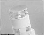
图1为本发明实施例中的一种光纤谐振式法布里珀罗超声传感器件的结构示意图;1 is a schematic structural diagram of an optical fiber resonant Fabry-Perot ultrasonic sensor device in an embodiment of the present invention;
图2为本发明实施例中的一种光纤谐振式法布里珀罗超声传感器件的结构俯视图;2 is a top view of the structure of an optical fiber resonant Fabry-Perot ultrasonic sensor device according to an embodiment of the present invention;
图3为本发明实施例中制备传感器结构拍摄SEM图像;FIG. 3 is an SEM image taken by preparing a sensor structure in an embodiment of the present invention;
图4为本发明实施例中制备传感器测试实验装置示意图;4 is a schematic diagram of an experimental device for preparing a sensor test in an embodiment of the present invention;
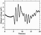
图5为本发明实施例中对传感器测试后得到的脉冲响应信号时域图像;5 is a time domain image of an impulse response signal obtained after testing a sensor in an embodiment of the present invention;
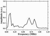
图6为本发明实施例中对传感器测试后得到的脉冲响应信号时域图像对应快速傅里叶变换解调出超声波频率信号;6 is an ultrasonic frequency signal obtained by demodulating the time domain image of the impulse response signal obtained after the sensor is tested according to the fast Fourier transform in the embodiment of the present invention;
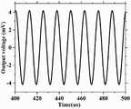
图7为本发明实施例中对传感器测试后得到的频率为80kHz连续正弦波信号时域图像;7 is a time domain image of a continuous sine wave signal with a frequency of 80 kHz obtained after the sensor is tested in an embodiment of the present invention;
图8为本发明实施例中对传感器测试后得到的800kHz连续正弦波信号时域图像。FIG. 8 is a time domain image of an 800 kHz continuous sine wave signal obtained after the sensor is tested in an embodiment of the present invention.
图中:1-单模光纤,2-圆形连接膜片,3-支撑弹性体,4-反射膜片。In the picture: 1-single-mode fiber, 2-circular connecting diaphragm, 3-supporting elastomer, 4-reflecting diaphragm.
具体实施方式Detailed ways
下面通过具体实施方式进一步说明。The following is further described through specific embodiments.
本发明提供了一种光纤谐振式法布里珀罗超声传感器件,由双光子聚合3D打印技术制备得到,打印的超声传感器结构位于光纤端面,其结构紧凑,整体体积尺寸小于100微米,并且利用弹簧和反射膜片的线弹性特性,可同时实现对低频和高频超声波探测。The invention provides an optical fiber resonance type Fabry-Perot ultrasonic sensor device, which is prepared by two-photon polymerization 3D printing technology. The printed ultrasonic sensor structure is located on the end face of the optical fiber, and the structure is compact, and the overall volume size is less than 100 microns. The linear elastic properties of the spring and the reflective diaphragm can simultaneously realize the detection of low-frequency and high-frequency ultrasonic waves.
如图1和图2所示,本发明提出的光纤谐振式法布里珀罗超声传感器件的结构包括单模光纤1、圆形连接膜片2、支撑弹性体3和反射膜片4。其中,所述的连接膜片2、支撑弹性体3、反射膜片4均为打印结构,连接膜片2与单模光纤起到连接作用,保持结构稳定,支撑弹性体3用于支撑反射膜片4,由支撑弹性体和反射膜片构成法布里珀罗谐振腔。As shown in FIG. 1 and FIG. 2 , the structure of the optical fiber resonant Fabry-Perot ultrasonic sensor device proposed by the present invention includes a single-mode
本实施例中,单模光纤1的直径为125微米,使用的商用双光子3D打印机为Nanoscribe公司Professional GTII型号,材料为光敏材料IP-DIP材料,该材料具有较低的杨氏模量,具有较高的声压灵敏度,打印超声传感器的连接膜片2厚度为5~10微米,直径为80~120微米;支撑弹性体采用支撑弹簧结构,数量为4,弹簧参数可以根据所需要探测超声频率进行调整,反射膜片4厚度为3~10微米,直径为80~120微米,同样可以根据所需要探测超声波频率进行调整。In this embodiment, the diameter of the single-
本发明的工作原理是基于多光束干涉原理,其中连接膜片2和反射膜片4构成法布里珀罗开放腔体,当输入光从单模光纤1输入到光纤端面和连接膜片2时,部分光会反射回单模光纤1,将之称为第一反射光;光纤与连接膜片交界面反射率为R1,因此部分光穿过连接膜片2,在连接膜片和空气交界面同样会发生发射,但反射光强度微弱可以忽略不计,前向透射光传播时会在空气与反射膜片4处反射并进入单模光纤1,将之称为第二反射光,空气与反射膜片交界面反射率为R2;第二反射光与第一反射光进行干涉,干涉反射光强度IR表达式如下式所示。The working principle of the present invention is based on the principle of multi-beam interference, in which the connecting

其中,I0表示入射信号光强度,n表示法布里珀罗腔体内部折射率,λ表示信号光波长,L表示法布里珀罗腔体长度。Among them, I0 represents the intensity of the incident signal light, n represents the internal refractive index of the Fabry-Perot cavity, λ represents the wavelength of the signal light, and L represents the length of the Fabry-Perot cavity.
当谐振腔内折射率和入射光波长保持不变时,外部超声压力作用于反射膜片4,弹簧和反射膜片会发生变形,改变法布里珀罗腔体长度L,对应反射光强发生变化,通过解调出相应光强,能够有效地解调出超声波信号强度和频率信息。When the refractive index in the resonator and the wavelength of the incident light remain unchanged, the external ultrasonic pressure acts on the
由于不同结构具有不同的共振频率信息,对于弹簧结构而言,支撑弹簧结构特征频率是处于低频振动特性,弹簧结构共振频率表达式为公式(2),对于反射膜片,具有较高的高频振动特性,反射膜片共振频率表达式为公式(3),对于不同超声波频率,当输入超声波频率为低频时,能够利用弹簧的低频响应,实现低频率信息探测,且弹簧形变量较大,探测灵敏度高;当输入超声波频率为高频信号时,利用反射膜片的高频振动特性,实现对高频信号的探测,但探测灵敏度降低,即该超声传感器能够实现同时对超声信号高频信号分量和低频信号分量的测量。Since different structures have different resonance frequency information, for the spring structure, the characteristic frequency of the support spring structure is in the low frequency vibration characteristic, and the resonance frequency expression of the spring structure is formula (2). Vibration characteristics, the expression of the resonant frequency of the reflective diaphragm is formula (3). For different ultrasonic frequencies, when the input ultrasonic frequency is low frequency, the low frequency response of the spring can be used to realize the detection of low frequency information, and the spring deformation is large, and the detection High sensitivity; when the input ultrasonic frequency is a high-frequency signal, the high-frequency vibration characteristics of the reflective diaphragm are used to detect the high-frequency signal, but the detection sensitivity is reduced, that is, the ultrasonic sensor can simultaneously detect the high-frequency signal component of the ultrasonic signal and measurement of low frequency signal components.


其中,f1表示单根弹簧最低阶共振频率表达式,rs表示弹簧截面圆半径,R表示弹簧中径,nt表示弹簧有效匝数,f2表示反射膜片最低阶共振频率表达式,h表示膜片厚度,rm表示膜片半径,ρ表示材料密度,v表示材料泊松比,E表示材料杨氏模量。Among them, f1 is the expression of the lowest-order resonance frequency of a single spring,rs is the radius of the spring section, R is the middle diameter of the spring, nt is the effective number of turns of the spring, f2 is the expression of the lowest-order resonance frequency of the reflective diaphragm, h is the thickness of the diaphragm, rm is the radius of the diaphragm, ρ is the density of the material,v is the Poisson's ratio of the material, and E is the Young's modulus of the material.
本实施例中的连接膜片与单模光纤起到连接作用,还可以根据实际需求设置柱形底座,可将连接膜片嵌入柱形底座内。如图3为制备传感器结构示意图,其中底座结构为圆形底座,底座直径为100微米,连接膜片厚度为10微米,弹簧结构的弹簧截面圆直径为6微米、中径6微米、匝数为5、轴向间距为10微米,反射膜片4厚度为5微米,直径为100微米。In this embodiment, the connection diaphragm and the single-mode optical fiber play a role of connection, and a cylindrical base can also be provided according to actual requirements, and the connection diaphragm can be embedded in the cylindrical base. Figure 3 is a schematic diagram of the prepared sensor structure, in which the base structure is a circular base, the diameter of the base is 100 microns, the thickness of the connecting diaphragm is 10 microns, and the spring cross-section circle diameter of the spring structure is 6 microns, the middle diameter is 6 microns, and the number of turns is 5. The axial spacing is 10 microns, the thickness of the
本发明的光纤谐振式法布里珀罗超声传感器件通过调节传感器结构的几何尺寸,可以有效拓宽传感器的频率响应带宽,其中调节弹簧的几何参数即弹簧半径、中径、匝数、轴向间距参数,可以调整该超声传感器在低频情况下对应超声频率响应范围和声压响应灵敏度,通过调节圆形反射膜片几何参数即膜片厚度和直径,能够调整改超声传感器在高频情况下对应超声频率响应范围。The optical fiber resonance type Fabry-Perot ultrasonic sensor device of the present invention can effectively widen the frequency response bandwidth of the sensor by adjusting the geometric size of the sensor structure, wherein the geometric parameters of the spring are adjusted, that is, the spring radius, the middle diameter, the number of turns, and the axial spacing. parameters, the ultrasonic frequency response range and sound pressure response sensitivity of the ultrasonic sensor can be adjusted at low frequencies. By adjusting the geometric parameters of the circular reflective diaphragm, that is, the thickness and diameter of the diaphragm, the ultrasonic sensor can be adjusted to respond to ultrasonic waves at high frequencies. frequency response range.
为了对本实施例中制备得到的超声传感器频率响应特性进行测试分析,搭建了图4所示实验装置,由超声声源部分、光学超声传感器部分和数据处理部分三部分构成。所述的超声声源部分由信号发生器和超声换能器构成,本实施例中采用压电换能器;所述的光学超声传感器部分由可调谐激器、光纤环形器、光纤端弹簧膜片式法布里珀罗超声传感器、光电探测器和示波器构成;所述的数据处理部分包括数据采集器和电脑组成。In order to test and analyze the frequency response characteristics of the ultrasonic sensor prepared in this example, the experimental device shown in FIG. 4 is built, which is composed of three parts: the ultrasonic sound source part, the optical ultrasonic sensor part and the data processing part. The ultrasonic sound source part is composed of a signal generator and an ultrasonic transducer, and a piezoelectric transducer is used in this embodiment; the optical ultrasonic sensor part is composed of a tunable exciter, an optical fiber circulator, and an optical fiber end spring film. It is composed of a chip Fabry-Perot ultrasonic sensor, a photodetector and an oscilloscope; the data processing part includes a data collector and a computer.
将种光纤谐振式法布里珀罗超声传感器件和超声换能器置于水箱中,用于测试水中的超声波信号。将信号发生器连接至水箱内的压电换能器,压电换能器产生超声波信号,超声波信号类型由信号发生器的输入决定;可调谐激光器输出单一波长的激光,通过光纤环形器到达光纤端弹簧膜片式法布里珀罗超声传感器,传感器接收到超声波信号后,传感器反射信号光通过环形器返回,并由光电探测器接收,通过光电探测器将反射光信号转换为电信号并在示波器上显示;同时通过数据采集器获取示波器上显示的数据进行处理,恢复采集到的超声波信号信息。A fiber-optic resonant Fabry-Perot ultrasonic sensor and ultrasonic transducer were placed in a water tank to test ultrasonic signals in water. Connect the signal generator to the piezoelectric transducer in the water tank, the piezoelectric transducer generates ultrasonic signals, and the type of ultrasonic signal is determined by the input of the signal generator; the tunable laser outputs laser light of a single wavelength, and reaches the optical fiber through the optical fiber circulator End spring diaphragm type Fabry-Perot ultrasonic sensor, after the sensor receives the ultrasonic signal, the reflected signal light of the sensor returns through the circulator, and is received by the photodetector, and the reflected light signal is converted into an electrical signal by the photodetector Displayed on the oscilloscope; at the same time, the data displayed on the oscilloscope is acquired through the data collector for processing, and the collected ultrasonic signal information is recovered.
本实施例中,利用图4所示的实验装置测试传感器频率响应带宽,信号发生器输入脉冲信号,将传感器与超声换能器正对放置,间隔可设置为1-10cm之间,超声换能器发出的超声波经过水域传输到达传感器,引起反射膜片变形振动,由于法布里珀罗腔体长度发生变化,传感器反射信号光强发生对应变化,经过环形器后传输到光电探测器上,通过示波器得到如图5所示为接收到冲击信号后时域图像,对接收到冲击信号频率分量进行分析,将采集到的冲击信号进行快速傅里叶变换后,得到各频率分量如图6所示,结果表明该传感器具有宽带的频率响应带宽,且存在一个低频特征频率分量(114kHz附近)和两个高频特征频率分量(687kHz和840kHz附近),其中,低频特征频率分量是利用弹簧结构振动探测得出,两个高频特征频率分量利用反射膜片结构振动探测,并且在三个特征频率附近处的幅度大小,即对应声压灵敏度,远高于其他频率处声压灵敏度,且能够稳定接收2MHz单频连续正弦波信号。In this embodiment, the experimental device shown in FIG. 4 is used to test the frequency response bandwidth of the sensor, the signal generator inputs a pulse signal, and the sensor and the ultrasonic transducer are placed facing each other, and the interval can be set to be between 1-10 cm. The ultrasonic wave emitted by the sensor is transmitted to the sensor through the water area, causing the reflective diaphragm to deform and vibrate. Due to the change of the length of the Fabry-Perot cavity, the light intensity of the reflected signal of the sensor changes correspondingly. After passing through the circulator, it is transmitted to the photodetector. The oscilloscope obtains the time domain image after receiving the shock signal as shown in Figure 5, analyzes the frequency components of the received shock signal, and performs fast Fourier transform on the collected shock signal, and obtains each frequency component as shown in Figure 6 , the results show that the sensor has a broadband frequency response bandwidth, and there is a low-frequency eigenfrequency component (near 114kHz) and two high-frequency eigenfrequency components (near 687kHz and 840kHz). It is concluded that the two high-frequency characteristic frequency components are detected by the vibration of the reflective diaphragm structure, and the amplitudes near the three characteristic frequencies, that is, the corresponding sound pressure sensitivity, are much higher than the sound pressure sensitivity at other frequencies, and can be received stably 2MHz single frequency continuous sine wave signal.
同样利用图4所示实验装置,测试传感器在单频超声波频率下响应,实验中信号发生器输入固定频率连续正弦波信号,将传感器与超声换能器正对放置,间隔可设置为1-10cm之间,信号发生器产生连续的正弦波信号输入到超声换能器上,超声换能器产生超声波经过水域后到达光纤端面超声传感器,引起反射膜片变形振动,由于法布里珀罗腔体长度发生变化,传感器反射信号光强发生对应变化,经过环形器后传输到光电探测器上,利用示波器记录采集到超声波信号,如图7和图8分别对应超声波对应80kHz和800kHz正弦波信号时域波形,该结果表明该传感器具有准确的探测单一频率超声波对应的频率信息。Similarly, the experimental device shown in Figure 4 is used to test the response of the sensor at a single-frequency ultrasonic frequency. In the experiment, the signal generator inputs a continuous sine wave signal of a fixed frequency, and the sensor and the ultrasonic transducer are placed in front of each other, and the interval can be set to 1-10cm In between, the signal generator generates a continuous sine wave signal and inputs it to the ultrasonic transducer. The ultrasonic transducer generates ultrasonic waves and reaches the ultrasonic sensor on the end face of the fiber after passing through the water area, causing the reflective diaphragm to deform and vibrate. Due to the Fabry-Perot cavity When the length changes, the light intensity of the reflected signal of the sensor changes correspondingly. After passing through the circulator, it is transmitted to the photodetector, and the ultrasonic signal is recorded and collected by the oscilloscope. As shown in Figure 7 and Figure 8, the ultrasonic wave corresponds to the time domain of the 80kHz and 800kHz sine wave signal respectively. The result shows that the sensor has accurate frequency information corresponding to the detection of a single frequency ultrasonic wave.
为了达到说明和描述的目的,本发明提供了前述的关于本发明的说明性示例。这并非旨在详尽地叙述本发明或将本发明限制为所叙述的精确形式,可根据上述说明可以进行修改和变更。选择和描述实施例是为了解释本发明的原理,并且作为本发明的实际应用,以使本领域技术人员能够在各种实施例中使用本发明,并且进行特定用途的各种修改。本领域的普通技术人员能从本发明公开的内容直接导出或联想到的所有变形,均应认为是本发明的保护范围。The foregoing illustrative examples of the invention have been provided for the purposes of illustration and description. It is not intended to be exhaustive or to limit the invention to the precise form described, as modifications and changes are possible in light of the above description. The embodiments were chosen and described in order to explain the principles of the invention and as a practical application of the invention to enable others skilled in the art to utilize the invention in various embodiments and with various modifications for a particular use. All deformations that those of ordinary skill in the art can directly derive or associate from the disclosure of the present invention shall be considered as the protection scope of the present invention.
Claims (10)
Translated fromChinesePriority Applications (1)
| Application Number | Priority Date | Filing Date | Title |
|---|---|---|---|
| CN202210619118.7ACN115014498B (en) | 2022-06-01 | 2022-06-01 | Optical fiber resonant Fabry-Perot ultrasonic sensor |
Applications Claiming Priority (1)
| Application Number | Priority Date | Filing Date | Title |
|---|---|---|---|
| CN202210619118.7ACN115014498B (en) | 2022-06-01 | 2022-06-01 | Optical fiber resonant Fabry-Perot ultrasonic sensor |
Publications (2)
| Publication Number | Publication Date |
|---|---|
| CN115014498Atrue CN115014498A (en) | 2022-09-06 |
| CN115014498B CN115014498B (en) | 2023-03-14 |
Family
ID=83072524
Family Applications (1)
| Application Number | Title | Priority Date | Filing Date |
|---|---|---|---|
| CN202210619118.7AActiveCN115014498B (en) | 2022-06-01 | 2022-06-01 | Optical fiber resonant Fabry-Perot ultrasonic sensor |
Country Status (1)
| Country | Link |
|---|---|
| CN (1) | CN115014498B (en) |
Cited By (6)
| Publication number | Priority date | Publication date | Assignee | Title |
|---|---|---|---|---|
| CN115507936A (en)* | 2022-10-26 | 2022-12-23 | 华北电力大学 | A Fiber Optic Sensor for High Frequency Vibration Detection |
| CN115643518A (en)* | 2022-09-07 | 2023-01-24 | 上海大学 | A double-diaphragm composite optical microphone |
| CN116164831A (en)* | 2023-03-03 | 2023-05-26 | 深圳技术大学 | A fiber optic ultrasonic sensor based on a spring resonator and its preparation method |
| CN116429238A (en)* | 2023-03-29 | 2023-07-14 | 深圳技术大学 | An optical fiber tip ultrasonic sensor and its preparation method |
| CN119118053A (en)* | 2024-09-12 | 2024-12-13 | 华中科技大学 | A method for forming a micro-nano cavity structure |
| CN120101921A (en)* | 2025-04-29 | 2025-06-06 | 国网江苏省电力有限公司电力科学研究院 | A step-type FP sensor based on MEMS technology and its preparation method |
Citations (9)
| Publication number | Priority date | Publication date | Assignee | Title |
|---|---|---|---|---|
| CN101762318A (en)* | 2010-01-21 | 2010-06-30 | 上海大学 | Optical fiber extrinsic Fabry-Perot interference ultrasonic sensing and detection device |
| US20110268384A1 (en)* | 2010-03-15 | 2011-11-03 | The Board Of Trustees Of The Leland Stanford Junior University | Optical-fiber-compatible acoustic sensor |
| CN103234619A (en)* | 2013-04-25 | 2013-08-07 | 重庆大学 | Optical fiber Fabry-Perot ultrasound hydrophone and system |
| US20140118749A1 (en)* | 2011-07-19 | 2014-05-01 | Canon Kabushiki Kaisha | Acoustic signal receiving apparatus and imaging apparatus |
| CN110160571A (en)* | 2019-05-31 | 2019-08-23 | 上海大学 | It is a kind of based on the Fabry Perot sensor of silicon core fibre and its preparation and application |
| CN110220584A (en)* | 2019-06-06 | 2019-09-10 | 中国科学院电子学研究所 | Optics acoustic sensor and optics sonic transducer including it |
| CN112284430A (en)* | 2020-10-23 | 2021-01-29 | 天津大学 | A multi-phase flow multi-parameter optical fiber detection device based on light-borne microwave interference |
| CN113138014A (en)* | 2021-05-19 | 2021-07-20 | 国网上海市电力公司 | Combined optical fiber EFPI broadband PD ultrasonic detection system |
| CN113804612A (en)* | 2021-09-09 | 2021-12-17 | 大连理工大学 | Optical fiber sensor for simultaneously monitoring stress and corrosion rate of steel bar |
- 2022
- 2022-06-01CNCN202210619118.7Apatent/CN115014498B/enactiveActive
Patent Citations (9)
| Publication number | Priority date | Publication date | Assignee | Title |
|---|---|---|---|---|
| CN101762318A (en)* | 2010-01-21 | 2010-06-30 | 上海大学 | Optical fiber extrinsic Fabry-Perot interference ultrasonic sensing and detection device |
| US20110268384A1 (en)* | 2010-03-15 | 2011-11-03 | The Board Of Trustees Of The Leland Stanford Junior University | Optical-fiber-compatible acoustic sensor |
| US20140118749A1 (en)* | 2011-07-19 | 2014-05-01 | Canon Kabushiki Kaisha | Acoustic signal receiving apparatus and imaging apparatus |
| CN103234619A (en)* | 2013-04-25 | 2013-08-07 | 重庆大学 | Optical fiber Fabry-Perot ultrasound hydrophone and system |
| CN110160571A (en)* | 2019-05-31 | 2019-08-23 | 上海大学 | It is a kind of based on the Fabry Perot sensor of silicon core fibre and its preparation and application |
| CN110220584A (en)* | 2019-06-06 | 2019-09-10 | 中国科学院电子学研究所 | Optics acoustic sensor and optics sonic transducer including it |
| CN112284430A (en)* | 2020-10-23 | 2021-01-29 | 天津大学 | A multi-phase flow multi-parameter optical fiber detection device based on light-borne microwave interference |
| CN113138014A (en)* | 2021-05-19 | 2021-07-20 | 国网上海市电力公司 | Combined optical fiber EFPI broadband PD ultrasonic detection system |
| CN113804612A (en)* | 2021-09-09 | 2021-12-17 | 大连理工大学 | Optical fiber sensor for simultaneously monitoring stress and corrosion rate of steel bar |
Non-Patent Citations (2)
| Title |
|---|
| HUI WANG 等: "A miniaturized optical fiber microphone with concentric nanorings grating and microsprings structured diaphragm", 《OPTICS & LASER TECHNOLOGY》* |
| 魏鹤鸣 等: "光纤超声安全监测研究进展", 《激光与光电子学进展》* |
Cited By (7)
| Publication number | Priority date | Publication date | Assignee | Title |
|---|---|---|---|---|
| CN115643518A (en)* | 2022-09-07 | 2023-01-24 | 上海大学 | A double-diaphragm composite optical microphone |
| CN115643518B (en)* | 2022-09-07 | 2025-06-13 | 上海大学 | A double-diaphragm composite optical microphone |
| CN115507936A (en)* | 2022-10-26 | 2022-12-23 | 华北电力大学 | A Fiber Optic Sensor for High Frequency Vibration Detection |
| CN116164831A (en)* | 2023-03-03 | 2023-05-26 | 深圳技术大学 | A fiber optic ultrasonic sensor based on a spring resonator and its preparation method |
| CN116429238A (en)* | 2023-03-29 | 2023-07-14 | 深圳技术大学 | An optical fiber tip ultrasonic sensor and its preparation method |
| CN119118053A (en)* | 2024-09-12 | 2024-12-13 | 华中科技大学 | A method for forming a micro-nano cavity structure |
| CN120101921A (en)* | 2025-04-29 | 2025-06-06 | 国网江苏省电力有限公司电力科学研究院 | A step-type FP sensor based on MEMS technology and its preparation method |
Also Published As
| Publication number | Publication date |
|---|---|
| CN115014498B (en) | 2023-03-14 |
Similar Documents
| Publication | Publication Date | Title |
|---|---|---|
| CN115014498B (en) | Optical fiber resonant Fabry-Perot ultrasonic sensor | |
| Kilic et al. | Miniature photonic-crystal hydrophone optimized for ocean acoustics | |
| US10495508B2 (en) | Phase-front-modulation sensor | |
| CN103528665A (en) | Novel Fabry-Perot interference MEMS (Micro Electro Mechanical System) sound wave sensor | |
| CN108375412A (en) | High sensitivity optical fiber sonac based on microcantilever beam | |
| CN106092901B (en) | A Surface Wave-Based Acoustic Signal Detector and Reflection Photoacoustic Microscope | |
| CN103152684B (en) | Optical-fiber microphone probe | |
| CN110849464B (en) | A fiber-optic Faber sound sensor based on hub-shaped diaphragm | |
| CN203551100U (en) | Novel Fabry-Perot interference-type MEMS sound wave sensor | |
| CN109945965A (en) | Support beam arm type sensitive diaphragm for fiber optic EFPI ultrasonic sensor | |
| Jo et al. | Highly sensitive phase-front-modulation fiber acoustic sensor | |
| Wu et al. | Low-cost rapid miniature optical pressure sensors for blast wave measurements | |
| CN104792401B (en) | Preparation method of fiber grating hydrophone for measuring near-field sound pressure distribution of high-frequency transducer | |
| CN103152685B (en) | Based on the fiber microphone of FP principle of interference | |
| CN116067477A (en) | An Ultrasonic Sensor Based on Diaphragm Vibration-Coupled Waveguide Microring | |
| CN106323444A (en) | Inclined optical fiber grating ultrasonic sensor | |
| Yin et al. | Highly sensitive ultrasonic sensor based on polymer Bragg grating and its application for 3D imaging of seismic physical model | |
| CN102353856B (en) | Method for measuring electrostrictive coefficient by using multi-beam laser heterodyne quadratic harmonic method | |
| CN116952359A (en) | Optical fiber end waveguide micro-ring ultrasonic sensor | |
| CN115166062B (en) | All-optical ultrasonic detector based on differential interference and detection method | |
| CN102253002B (en) | Method for measuring electrostriction coefficient of sinusoidal modulation multi-beam laser heterodyne second harmonic waves by utilizing Doppler vibration mirror | |
| CN116164831A (en) | A fiber optic ultrasonic sensor based on a spring resonator and its preparation method | |
| CN213779260U (en) | An acoustic wave measurement device based on a Y-shaped cavity orthogonally polarized laser | |
| CN116269478A (en) | Optical F-P ultrasonic probe for photoacoustic endoscopic imaging | |
| CN204535846U (en) | Measure the optical fiber grating sonic device of high-frequency transducer near-field acoustic pressure distribution |
Legal Events
| Date | Code | Title | Description |
|---|---|---|---|
| PB01 | Publication | ||
| PB01 | Publication | ||
| SE01 | Entry into force of request for substantive examination | ||
| SE01 | Entry into force of request for substantive examination | ||
| GR01 | Patent grant | ||
| GR01 | Patent grant |