CN115009053A - System and method for dynamic wireless charging coil positioning system for segmented electric vehicles - Google Patents
System and method for dynamic wireless charging coil positioning system for segmented electric vehiclesDownload PDFInfo
- Publication number
- CN115009053A CN115009053ACN202210818947.8ACN202210818947ACN115009053ACN 115009053 ACN115009053 ACN 115009053ACN 202210818947 ACN202210818947 ACN 202210818947ACN 115009053 ACN115009053 ACN 115009053A
- Authority
- CN
- China
- Prior art keywords
- coil
- transmitting
- receiving
- wireless charging
- receiving coil
- Prior art date
- Legal status (The legal status is an assumption and is not a legal conclusion. Google has not performed a legal analysis and makes no representation as to the accuracy of the status listed.)
- Granted
Links
Images


Classifications
- B—PERFORMING OPERATIONS; TRANSPORTING
- B60—VEHICLES IN GENERAL
- B60L—PROPULSION OF ELECTRICALLY-PROPELLED VEHICLES; SUPPLYING ELECTRIC POWER FOR AUXILIARY EQUIPMENT OF ELECTRICALLY-PROPELLED VEHICLES; ELECTRODYNAMIC BRAKE SYSTEMS FOR VEHICLES IN GENERAL; MAGNETIC SUSPENSION OR LEVITATION FOR VEHICLES; MONITORING OPERATING VARIABLES OF ELECTRICALLY-PROPELLED VEHICLES; ELECTRIC SAFETY DEVICES FOR ELECTRICALLY-PROPELLED VEHICLES
- B60L53/00—Methods of charging batteries, specially adapted for electric vehicles; Charging stations or on-board charging equipment therefor; Exchange of energy storage elements in electric vehicles
- B60L53/10—Methods of charging batteries, specially adapted for electric vehicles; Charging stations or on-board charging equipment therefor; Exchange of energy storage elements in electric vehicles characterised by the energy transfer between the charging station and the vehicle
- B60L53/12—Inductive energy transfer
- B60L53/126—Methods for pairing a vehicle and a charging station, e.g. establishing a one-to-one relation between a wireless power transmitter and a wireless power receiver
- B—PERFORMING OPERATIONS; TRANSPORTING
- B60—VEHICLES IN GENERAL
- B60L—PROPULSION OF ELECTRICALLY-PROPELLED VEHICLES; SUPPLYING ELECTRIC POWER FOR AUXILIARY EQUIPMENT OF ELECTRICALLY-PROPELLED VEHICLES; ELECTRODYNAMIC BRAKE SYSTEMS FOR VEHICLES IN GENERAL; MAGNETIC SUSPENSION OR LEVITATION FOR VEHICLES; MONITORING OPERATING VARIABLES OF ELECTRICALLY-PROPELLED VEHICLES; ELECTRIC SAFETY DEVICES FOR ELECTRICALLY-PROPELLED VEHICLES
- B60L53/00—Methods of charging batteries, specially adapted for electric vehicles; Charging stations or on-board charging equipment therefor; Exchange of energy storage elements in electric vehicles
- B60L53/30—Constructional details of charging stations
- B60L53/35—Means for automatic or assisted adjustment of the relative position of charging devices and vehicles
- B60L53/38—Means for automatic or assisted adjustment of the relative position of charging devices and vehicles specially adapted for charging by inductive energy transfer
- Y—GENERAL TAGGING OF NEW TECHNOLOGICAL DEVELOPMENTS; GENERAL TAGGING OF CROSS-SECTIONAL TECHNOLOGIES SPANNING OVER SEVERAL SECTIONS OF THE IPC; TECHNICAL SUBJECTS COVERED BY FORMER USPC CROSS-REFERENCE ART COLLECTIONS [XRACs] AND DIGESTS
- Y02—TECHNOLOGIES OR APPLICATIONS FOR MITIGATION OR ADAPTATION AGAINST CLIMATE CHANGE
- Y02T—CLIMATE CHANGE MITIGATION TECHNOLOGIES RELATED TO TRANSPORTATION
- Y02T10/00—Road transport of goods or passengers
- Y02T10/60—Other road transportation technologies with climate change mitigation effect
- Y02T10/70—Energy storage systems for electromobility, e.g. batteries
- Y—GENERAL TAGGING OF NEW TECHNOLOGICAL DEVELOPMENTS; GENERAL TAGGING OF CROSS-SECTIONAL TECHNOLOGIES SPANNING OVER SEVERAL SECTIONS OF THE IPC; TECHNICAL SUBJECTS COVERED BY FORMER USPC CROSS-REFERENCE ART COLLECTIONS [XRACs] AND DIGESTS
- Y02—TECHNOLOGIES OR APPLICATIONS FOR MITIGATION OR ADAPTATION AGAINST CLIMATE CHANGE
- Y02T—CLIMATE CHANGE MITIGATION TECHNOLOGIES RELATED TO TRANSPORTATION
- Y02T90/00—Enabling technologies or technologies with a potential or indirect contribution to GHG emissions mitigation
- Y02T90/10—Technologies relating to charging of electric vehicles
- Y02T90/14—Plug-in electric vehicles
Landscapes
- Engineering & Computer Science (AREA)
- Power Engineering (AREA)
- Transportation (AREA)
- Mechanical Engineering (AREA)
- Computer Networks & Wireless Communication (AREA)
- Current-Collector Devices For Electrically Propelled Vehicles (AREA)
- Charge And Discharge Circuits For Batteries Or The Like (AREA)
Abstract
Translated fromChinese
Description
Translated fromChinese技术领域technical field
本发明属于无线电能传输技术领域,具体涉及一种适用于分段式电动汽车动态无线充电线圈定位系统及方法。The invention belongs to the technical field of wireless power transmission, and in particular relates to a dynamic wireless charging coil positioning system and method suitable for segmented electric vehicles.
背景技术Background technique
“碳达峰,碳中和”的提出推进了能源变革的进程。道路交通是我国重要的碳排放源之一,目前已成为能源变革的关键领域。高能效、低排放的电动汽车替代传统燃油汽车成为行业的必然趋势,但其发展受到了停留式充电和高昂电池成本的掣肘。电动汽车动态无线充电(Electric Vehicel Dynamic Wireless Charging,EV-DWC)技术实现了“边走边充”的新型能量补给方式,可以有效降低车载电池成本,提高续航里程。The proposal of "carbon peak, carbon neutrality" promotes the process of energy transformation. Road transportation is one of the important carbon emission sources in my country, and it has become a key area of energy transformation. The replacement of traditional fuel vehicles by energy-efficient, low-emission electric vehicles has become an inevitable trend in the industry, but its development is hampered by parking charging and high battery costs. Electric vehicle dynamic wireless charging (Electric Vehicel Dynamic Wireless Charging, EV-DWC) technology realizes a new energy supply method of "charging while walking", which can effectively reduce the cost of the vehicle battery and improve the cruising range.
短分段式EV-DWC系统快速高精度定位问题目前成为该技术领域的研究热点之一。为提升短分段式动态无线充电系统的充电效率,需要实现精准的车辆定位功能以便系统电源进行实时切换,尤其对于高速行驶的电动汽车实现定位系统快速响应也极为重要。但目前电动汽车动态定位技术多依赖发射端与电动汽车的双端通讯,定位控制环节众多,响应时间长,因此有必要研究一种可以通过单边数据测量进行汽车位置识别的定位方法。The problem of fast and high-precision positioning of short-segment EV-DWC system has become one of the research hotspots in this technical field. In order to improve the charging efficiency of the short-segment dynamic wireless charging system, it is necessary to realize the precise vehicle positioning function so that the system power can be switched in real time, especially for the high-speed electric vehicle, it is also extremely important to realize the rapid response of the positioning system. However, the current dynamic positioning technology of electric vehicles mostly relies on the two-terminal communication between the transmitter and the electric vehicle. There are many positioning control links and a long response time. Therefore, it is necessary to develop a positioning method that can identify the vehicle position through unilateral data measurement.
发明内容SUMMARY OF THE INVENTION
为解决现有技术存在的问题,本发明提出了一种适用于分段式电动汽车动态无线充电线圈定位系统及方法,实现对电动汽车在路面行驶过程中的实时电能补给。In order to solve the problems existing in the prior art, the present invention proposes a dynamic wireless charging coil positioning system and method suitable for segmented electric vehicles, so as to realize real-time electric energy replenishment for electric vehicles during road driving.
技术方案:为了实现上述目的,本发明的技术方案为:Technical scheme: in order to achieve the above purpose, the technical scheme of the present invention is:
一种适用于分段式电动汽车动态无线充电线圈定位系统,包括电能传输模块以及定位模块;所述电能传输模块包括电能发射端、分段式磁耦合机构和电能接收端;所述电能发射端包括逆变电源和发射端补偿电路;所述的分段式磁耦合机构包括连续固定间隔铺设的发射线圈和接收线圈,每个发射线圈串联发射端补偿电路;所述的电能接收端包括接收端补偿电路、整流电路、电动汽车车载电池负载,所述的接收端补偿电路的输入端与接收线圈输出端连接,接收端补偿电路的输出端与整流电路的输入端连接,整流电路输出端接电池负载;所述定位模块包括采样模块、相位比较器和频率驱动模块,所述采样模块实时采集逆变电源的输出电压和输出电流,并将源端信号发送至相位比较器,相位比较器通过采集的源端信号对频率驱动模块进行控制,以控制逆变电源的输出频率。A dynamic wireless charging coil positioning system suitable for segmented electric vehicles includes a power transmission module and a positioning module; the power transmission module includes a power transmitting end, a segmented magnetic coupling mechanism and a power receiving end; the power transmitting end It includes an inverter power supply and a transmitter compensation circuit; the segmented magnetic coupling mechanism includes a transmitter coil and a receiver coil laid continuously at fixed intervals, and each transmitter coil is connected in series with a transmitter compensation circuit; the power receiving end includes a receiving end Compensation circuit, rectifier circuit, electric vehicle vehicle battery load, the input end of the receiving end compensation circuit is connected with the output end of the receiving coil, the output end of the receiving end compensation circuit is connected with the input end of the rectifier circuit, and the output end of the rectifier circuit is connected with the battery load; the positioning module includes a sampling module, a phase comparator and a frequency drive module, the sampling module collects the output voltage and output current of the inverter power supply in real time, and sends the source signal to the phase comparator, and the phase comparator collects the The source signal of the inverter controls the frequency drive module to control the output frequency of the inverter power supply.
进一步地,所述分段式磁耦合机构的发射线圈与接收线圈相同,发射线圈寄生电阻R1-i与接收线圈寄生电阻R2相同,发射线圈连续铺设在路面下,接收线圈安装在电动汽车底盘下。Further, the transmitting coil of the segmented magnetic coupling mechanism is the same as the receiving coil, the parasitic resistance R1-i of the transmitting coil is the same as the parasitic resistance R2 of the receiving coil, the transmitting coil is continuously laid under the road surface, and the receiving coil is installed in the electric vehicle. under the chassis.
进一步地,所述的发射端补偿电路包括谐振电容C1-i与发射线圈L1-i串联,构成串联谐振;所述的接收端补偿电路包括谐振电容C2与接收线圈L2串联,构成串联谐振,设传能电路的谐振工作频率为ω0,则满足式(1):Further, the compensation circuit at the transmitting end includes a resonant capacitor C1- i connected in series with the transmitting coil L1-i to form a series resonance; the compensation circuit at the receiving end includes a resonance capacitor C2 connected in series with the receiving coil L2 to form a series resonance. For series resonance, if the resonant operating frequency of the energy transfer circuit is ω0 , the equation (1) is satisfied:

式中,L1-i为第i个发射线圈的自感,C1-i为第i个发射线圈的串联补偿电容,L2为接收线圈的自感,C2为接收线圈的串联补偿电容。In the formula, L1-i is the self-inductance of the i-th transmitter coil, C1-i is the series compensation capacitor of the i-th transmitter coil, L2 is the self-inductance of the receiver coil, and C2 is the series compensation capacitor of the receiver coil. .
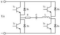
进一步地,所述逆变电源为电压型全桥逆变电源,包括四个SiC-MOSFET开关管和四个不控型二极管,SiC-MOSFET开关管与不控型二极管反向并联。Further, the inverter power supply is a voltage-type full-bridge inverter power supply, including four SiC-MOSFET switch tubes and four uncontrolled diodes, and the SiC-MOSFET switch tubes and the uncontrolled diodes are in reverse parallel connection.
进一步地,所述整流电路为单相桥式不控整流电路,包括4个不可控二极管和稳压电容。Further, the rectifier circuit is a single-phase bridge-type uncontrolled rectifier circuit, including four uncontrollable diodes and a voltage-stabilizing capacitor.
一种用上述适用于分段式电动汽车动态无线充电线圈定位系统进行电动汽车动态无线充电的线圈定位方法,该方法包括如下步骤:A coil positioning method for dynamic wireless charging of electric vehicles using the above-mentioned dynamic wireless charging coil positioning system for segmented electric vehicles, the method comprising the following steps:
(1)控制逆变电源的工作频率在0~ω0之间进行频率扫描,采样模块实时采集逆变电源的输出电压

(2)相位比较器实时比较


式中,L2为接收线圈的自感,L为简化后的发射与接收线圈自感,C1-i为第i个发射线圈的串联补偿电容,C2为接收端补偿电路的电容,C为简化后的发射与接收线圈的补偿电容。In the formula, L2 is the self-inductance of the receiving coil, L is the simplified self-inductance of the transmitting and receiving coils, C1-i is the series compensation capacitance of the i-th transmitting coil, C2 is the capacitance of the compensation circuit at the receiving end, C Compensation capacitance for the simplified transmit and receive coils.
(3)通过仿真或实验测得发射线圈与接收线圈的耦合系数k与相对位置的关系,即k(x);(3) The relationship between the coupling coefficient k of the transmitting coil and the receiving coil and the relative position is measured by simulation or experiment, that is, k(x);
(4)计算此时发射线圈与接收线圈的耦合系数kc:(4) Calculate the coupling coefficient kc of the transmitting coil and the receiving coil at this time:

式中,RL为负载等效电阻,R2为接收线圈的寄生电阻。In the formula, RL is the equivalent resistance of the load, and R2 is the parasitic resistance of the receiving coil.
(5)将kc带入k(x)曲线中可实时获取接收线圈的位置,当接收线圈位于发射线圈上方时,控制逆变电源输出频率为ω0,在谐振状态下对接收端进行实时供电。(5) Bring kc into the k(x) curve to obtain the position of the receiving coil in real time. When the receiving coil is located above the transmitting coil, the output frequency of the inverter power supply is controlled to be ω0 , and the receiving end is powered in real time under the resonance state. .
本发明有益效果:Beneficial effects of the present invention:
本发明针对电动汽车动态无线充电系统高精度定位这一技术背景,提供一种适用于电动汽车动态无线充电的线圈定位系统,通过频率扫描的方法获取源端的输出电气参数便可实时获取接收端相对发射线圈的位置,摆脱了电动汽车动态无线充电定位需要双端通讯的问题,为无线电能传输技术在电动汽车上的应用提供了新的思路。Aiming at the technical background of high-precision positioning of the dynamic wireless charging system of electric vehicles, the present invention provides a coil positioning system suitable for dynamic wireless charging of electric vehicles. The position of the transmitting coil gets rid of the problem that the dynamic wireless charging positioning of electric vehicles requires two-terminal communication, and provides a new idea for the application of wireless power transmission technology in electric vehicles.
附图说明Description of drawings
图1是本发明所述适用于电动汽车动态无线充电的线圈定位系统示意图;1 is a schematic diagram of a coil positioning system suitable for dynamic wireless charging of electric vehicles according to the present invention;
图2是电能传输通路的电路图;2 is a circuit diagram of a power transmission path;
图3是负载端变电模块等效电路图。Figure 3 is an equivalent circuit diagram of a load-side substation module.
具体实施方式Detailed ways
下面结合附图对本申请提供的磁耦合机构设计做详细说明。The design of the magnetic coupling mechanism provided by the present application will be described in detail below with reference to the accompanying drawings.
如图1所示,一种适用于电动汽车动态无线充电的线圈定位系统,所述电能传输模块包括电能发射端、分段式磁耦合机构和电能接收端;所述电能发射端包括高频逆变电源和补偿电路;所述的分段式磁耦合机构包括连续固定间隔铺设的发射线圈和接收线圈,每个发射线圈串联补偿电路,其输入端与逆变电源的输出端连接;所述的电能接收端包括整流电路与电动汽车车载电池负载,所述的整流电路输入端与接收线圈输出端连接,整流电路输出端接电池负载;所述定位模块包括电流采样模块、相位比较器和频率驱动模块,所述电流采样模块实时采集逆变电源的输出电压和输出电流,并将源端信号发送至相位比较器,相位比较器通过采集的信号对频率驱动模块进行控制,以控制逆变电源的输出频率。As shown in Figure 1, a coil positioning system suitable for dynamic wireless charging of electric vehicles, the power transmission module includes a power transmitter, a segmented magnetic coupling mechanism and a power receiver; the power transmitter includes a high-frequency inverter a power transformer and a compensation circuit; the segmented magnetic coupling mechanism includes a transmitting coil and a receiving coil laid continuously at fixed intervals, each transmitting coil is connected in series with a compensation circuit, and its input end is connected to the output end of the inverter power supply; the said The power receiving end includes a rectifier circuit and an on-board battery load of an electric vehicle, the input end of the rectifier circuit is connected to the output end of the receiving coil, and the output end of the rectifier circuit is connected to the battery load; the positioning module includes a current sampling module, a phase comparator and a frequency drive module, the current sampling module collects the output voltage and output current of the inverter power supply in real time, and sends the source signal to the phase comparator, and the phase comparator controls the frequency drive module through the collected signal to control the inverter power supply. Output frequency.
如图2所示,


负载端电路如图3所示,其主要功能为将高频交流电改为直流电,为车端电池负载进行实时充电。The load-end circuit is shown in Figure 3. Its main function is to change the high-frequency alternating current to direct current to charge the vehicle-end battery load in real time.
基于上述一种适用于电动汽车动态无线充电的线圈定位系统定位原理与方法如下:The positioning principle and method based on the above-mentioned coil positioning system suitable for dynamic wireless charging of electric vehicles are as follows:
设X1=ωL1-1/ωC1,X2=ωL1-1/ωC1,根据图2列写电路的KVL方程:Set X1 =ωL1 -1/ωC1 , X2 =ωL1 -1/ωC1 , write the KVL equation of the circuit according to Figure 2:

则系统的输入阻抗Zin可表示为:Then the input impedance Zin of the system can be expressed as:

设X=ωL-1/ωC,并令Zin的虚部为0,在过耦合下系统存在三个谐振点:Let X=ωL-1/ωC, and let the imaginary part of Zin be 0, there are three resonance points in the system under over-coupling:

当系统工作频率为ω+,-时,得到输入阻抗为:When the operating frequency of the system is ω+,- , the input impedance is obtained as:

可知,当ω=ω+,-时,系统输入阻抗完全由系统寄生参数和负载阻值决定。将式(7)带入式(6)中反解,得到耦合系数的计算值kc:It can be known that when ω=ω+,- , the input impedance of the system is completely determined by the parasitic parameters of the system and the load resistance. Bring Equation (7) into Equation (6) for inverse solution to obtain the calculated value kc of the coupling coefficient:

通过比对接收线圈与发射线圈耦合系数k与相对位置的关系k(x),便可以识别当前接收线圈的位置,当接收线圈定位在发射线圈上方时,调整逆变电源的输出频率为ω0,实现对电动汽车接收端电能实时补给。By comparing the relationship between the coupling coefficient k of the receiving coil and the transmitting coil and the relative position k(x), the current position of the receiving coil can be identified. When the receiving coil is positioned above the transmitting coil, adjust the output frequency of the inverter to ω0, Real-time supply of electric energy to the receiving end of electric vehicles.
以上所述仅是本发明的技术方案,不能以此限定本发明的保护范围。对于本技术领域的技术人员来说,在不脱离本发明原理的前提下,依然可以对本发明做出修改和等同替换,其均落入本发明保护范围之内。The above descriptions are only the technical solutions of the present invention, which cannot limit the protection scope of the present invention. For those skilled in the art, without departing from the principles of the present invention, modifications and equivalent replacements can still be made to the present invention, which all fall within the protection scope of the present invention.
Claims (6)


Priority Applications (1)
| Application Number | Priority Date | Filing Date | Title |
|---|---|---|---|
| CN202210818947.8ACN115009053B (en) | 2022-07-13 | 2022-07-13 | Dynamic wireless charging coil positioning system and method suitable for sectional electric automobile |
Applications Claiming Priority (1)
| Application Number | Priority Date | Filing Date | Title |
|---|---|---|---|
| CN202210818947.8ACN115009053B (en) | 2022-07-13 | 2022-07-13 | Dynamic wireless charging coil positioning system and method suitable for sectional electric automobile |
Publications (2)
| Publication Number | Publication Date |
|---|---|
| CN115009053Atrue CN115009053A (en) | 2022-09-06 |
| CN115009053B CN115009053B (en) | 2025-09-19 |
Family
ID=83080025
Family Applications (1)
| Application Number | Title | Priority Date | Filing Date |
|---|---|---|---|
| CN202210818947.8AActiveCN115009053B (en) | 2022-07-13 | 2022-07-13 | Dynamic wireless charging coil positioning system and method suitable for sectional electric automobile |
Country Status (1)
| Country | Link |
|---|---|
| CN (1) | CN115009053B (en) |
Cited By (1)
| Publication number | Priority date | Publication date | Assignee | Title |
|---|---|---|---|---|
| CN115503515A (en)* | 2022-09-14 | 2022-12-23 | 哈尔滨工业大学(深圳) | A dynamic wireless charging system with multiple transmitting coils connected in parallel |
Citations (8)
| Publication number | Priority date | Publication date | Assignee | Title |
|---|---|---|---|---|
| CN107031443A (en)* | 2017-04-06 | 2017-08-11 | 深圳市华禹无线供电技术有限公司 | A kind of dynamic radio conducts electricity passage, road, system |
| CN107733093A (en)* | 2017-11-15 | 2018-02-23 | 哈尔滨理工大学 | A kind of Capacitance Coupled resonance type wireless energy transmission system and method |
| CN208376542U (en)* | 2018-06-20 | 2019-01-15 | 桂林电子科技大学 | A kind of electric car dynamic radio charge control system |
| CN109664793A (en)* | 2018-12-19 | 2019-04-23 | 国网江苏省电力有限公司 | A kind of monitoring method of the wireless charging automobile position based on ground induction coil |
| CN111016690A (en)* | 2018-10-09 | 2020-04-17 | 郑州宇通客车股份有限公司 | Wireless charging control method and device for electric automobile |
| CN210806854U (en)* | 2019-10-28 | 2020-06-19 | 华南理工大学 | A multi-frequency many-to-one wireless power supply system based on the principle of PT symmetry |
| WO2021027303A1 (en)* | 2019-08-09 | 2021-02-18 | 华为技术有限公司 | Chargeable-dischargeable energy storage apparatus, wireless charging system and electric vehicle |
| WO2022116413A1 (en)* | 2020-12-01 | 2022-06-09 | 浙江大学 | Variable circuit topology capable of switching wireless power transmission coil and compensation capacitor |
- 2022
- 2022-07-13CNCN202210818947.8Apatent/CN115009053B/enactiveActive
Patent Citations (8)
| Publication number | Priority date | Publication date | Assignee | Title |
|---|---|---|---|---|
| CN107031443A (en)* | 2017-04-06 | 2017-08-11 | 深圳市华禹无线供电技术有限公司 | A kind of dynamic radio conducts electricity passage, road, system |
| CN107733093A (en)* | 2017-11-15 | 2018-02-23 | 哈尔滨理工大学 | A kind of Capacitance Coupled resonance type wireless energy transmission system and method |
| CN208376542U (en)* | 2018-06-20 | 2019-01-15 | 桂林电子科技大学 | A kind of electric car dynamic radio charge control system |
| CN111016690A (en)* | 2018-10-09 | 2020-04-17 | 郑州宇通客车股份有限公司 | Wireless charging control method and device for electric automobile |
| CN109664793A (en)* | 2018-12-19 | 2019-04-23 | 国网江苏省电力有限公司 | A kind of monitoring method of the wireless charging automobile position based on ground induction coil |
| WO2021027303A1 (en)* | 2019-08-09 | 2021-02-18 | 华为技术有限公司 | Chargeable-dischargeable energy storage apparatus, wireless charging system and electric vehicle |
| CN210806854U (en)* | 2019-10-28 | 2020-06-19 | 华南理工大学 | A multi-frequency many-to-one wireless power supply system based on the principle of PT symmetry |
| WO2022116413A1 (en)* | 2020-12-01 | 2022-06-09 | 浙江大学 | Variable circuit topology capable of switching wireless power transmission coil and compensation capacitor |
Cited By (1)
| Publication number | Priority date | Publication date | Assignee | Title |
|---|---|---|---|---|
| CN115503515A (en)* | 2022-09-14 | 2022-12-23 | 哈尔滨工业大学(深圳) | A dynamic wireless charging system with multiple transmitting coils connected in parallel |
Also Published As
| Publication number | Publication date |
|---|---|
| CN115009053B (en) | 2025-09-19 |
Similar Documents
| Publication | Publication Date | Title |
|---|---|---|
| CN110450656B (en) | Electric automobile wireless charging closed-loop control system based on differential inductance | |
| US12388297B2 (en) | Wireless charging transmitter, wireless charging receiver, and wireless charging system | |
| CN109895640B (en) | Two-stage control system and control method for wireless charging of electric automobile | |
| CN108448693B (en) | Wireless power transmission system for AGV and control method thereof | |
| CN110654253A (en) | Combined control method for optimal efficiency of wireless charging system of electric automobile | |
| CN111532151B (en) | Wireless charging system and method for electric automobile | |
| CN107512176B (en) | A tram dynamic wireless power supply system and its efficiency optimization control method | |
| CN102969776A (en) | Wireless charging device of electronic automobile | |
| CN105207374A (en) | Wireless power transmission system and method as well as tracking-type transmitting coil devices | |
| CN106314187B (en) | A kind of control method of the short segmentation dynamic radio power supply system of electric vehicle | |
| CN113629891A (en) | A method for optimizing the efficiency of dynamic wireless power supply system for electric vehicles | |
| CN115503515A (en) | A dynamic wireless charging system with multiple transmitting coils connected in parallel | |
| CN113511085B (en) | Segmented coil type wireless charging system for electric automobile and control method | |
| CN116317205A (en) | No-communication WPT system and control method for inspection robot with parameter estimation capability | |
| CN110962633A (en) | Low-voltage high-current wireless charging system and method | |
| CN115009053A (en) | System and method for dynamic wireless charging coil positioning system for segmented electric vehicles | |
| Zhang | A review of wireless charging technology for electric vehicles | |
| Chen et al. | Analysis and design of wireless charging systems without extra components for load-independent constant current and voltage battery charging | |
| CN115395673A (en) | Electric vehicle wireless power transmission system and control method thereof | |
| CN116512947A (en) | Vehicle charging device and control method | |
| CN205429837U (en) | Closed loop wireless energy transmission system | |
| CN218243118U (en) | A Wireless Power Transmission System Based on Magnetically Coupled Resonant ICPT | |
| CN116581903A (en) | Segmented switching type dynamic wireless power supply system based on position detection coil | |
| Abdulhameed et al. | Design and tuning of lcc compensation networks for dd-ddq coils in dynamic wireless ev charging systems | |
| CN116154981A (en) | Transformer substation inspection robot dynamic wireless charging system based on anti-offset magnetic coupling mechanism |
Legal Events
| Date | Code | Title | Description |
|---|---|---|---|
| PB01 | Publication | ||
| PB01 | Publication | ||
| SE01 | Entry into force of request for substantive examination | ||
| SE01 | Entry into force of request for substantive examination | ||
| GR01 | Patent grant | ||
| GR01 | Patent grant |