CN115008906B - An aircraft multi-color inkjet printing device - Google Patents
An aircraft multi-color inkjet printing deviceDownload PDFInfo
- Publication number
- CN115008906B CN115008906BCN202210760809.9ACN202210760809ACN115008906BCN 115008906 BCN115008906 BCN 115008906BCN 202210760809 ACN202210760809 ACN 202210760809ACN 115008906 BCN115008906 BCN 115008906B
- Authority
- CN
- China
- Prior art keywords
- bowl
- shaped piece
- liquid storage
- ink box
- side wall
- Prior art date
- Legal status (The legal status is an assumption and is not a legal conclusion. Google has not performed a legal analysis and makes no representation as to the accuracy of the status listed.)
- Expired - Fee Related
Links
Images


Classifications
- B—PERFORMING OPERATIONS; TRANSPORTING
- B41—PRINTING; LINING MACHINES; TYPEWRITERS; STAMPS
- B41J—TYPEWRITERS; SELECTIVE PRINTING MECHANISMS, i.e. MECHANISMS PRINTING OTHERWISE THAN FROM A FORME; CORRECTION OF TYPOGRAPHICAL ERRORS
- B41J2/00—Typewriters or selective printing mechanisms characterised by the printing or marking process for which they are designed
- B41J2/005—Typewriters or selective printing mechanisms characterised by the printing or marking process for which they are designed characterised by bringing liquid or particles selectively into contact with a printing material
- B41J2/01—Ink jet
- B41J2/21—Ink jet for multi-colour printing
- B—PERFORMING OPERATIONS; TRANSPORTING
- B41—PRINTING; LINING MACHINES; TYPEWRITERS; STAMPS
- B41J—TYPEWRITERS; SELECTIVE PRINTING MECHANISMS, i.e. MECHANISMS PRINTING OTHERWISE THAN FROM A FORME; CORRECTION OF TYPOGRAPHICAL ERRORS
- B41J2/00—Typewriters or selective printing mechanisms characterised by the printing or marking process for which they are designed
- B41J2/005—Typewriters or selective printing mechanisms characterised by the printing or marking process for which they are designed characterised by bringing liquid or particles selectively into contact with a printing material
- B41J2/01—Ink jet
- B41J2/17—Ink jet characterised by ink handling
- B41J2/175—Ink supply systems ; Circuit parts therefor
- B41J2/17503—Ink cartridges
- B—PERFORMING OPERATIONS; TRANSPORTING
- B41—PRINTING; LINING MACHINES; TYPEWRITERS; STAMPS
- B41J—TYPEWRITERS; SELECTIVE PRINTING MECHANISMS, i.e. MECHANISMS PRINTING OTHERWISE THAN FROM A FORME; CORRECTION OF TYPOGRAPHICAL ERRORS
- B41J3/00—Typewriters or selective printing or marking mechanisms characterised by the purpose for which they are constructed
- B41J3/407—Typewriters or selective printing or marking mechanisms characterised by the purpose for which they are constructed for marking on special material
- B41J3/4073—Printing on three-dimensional objects not being in sheet or web form, e.g. spherical or cubic objects
Landscapes
- Engineering & Computer Science (AREA)
- Manufacturing & Machinery (AREA)
- Ink Jet (AREA)
Abstract
Description
Translated fromChinese技术领域technical field
本发明属于无人机和打印机技术领域,具体涉及一种飞行器多色喷墨打印装置。The invention belongs to the technical field of drones and printers, and in particular relates to an aircraft multi-color inkjet printing device.
背景技术Background technique
传统的喷涂打印机均是置于桌面上或地面上的固定设备,喷涂打印出的图案的体积会受到喷涂打印机自身尺寸大小的限制,若是需要打印出更大面积的产品,则需要配置规格更大的喷涂打印机,因此其灵活性极差,不能满足对大面积、非平面、以及特殊承印位置(例如高层建筑物的墙面)的喷涂需求。Traditional spraying printers are fixed devices placed on the table or on the ground. The volume of the printed pattern will be limited by the size of the spraying printer itself. If you need to print products with a larger area, you need to configure larger specifications Therefore, its flexibility is extremely poor, and it cannot meet the spraying requirements for large areas, non-planar, and special printing positions (such as the walls of high-rise buildings).
公开号为CN 112277309的专利申请公开了一种飞行式3D打印机,其以无人机为载体,在无人机上设置了喷涂装置,通过控制无人机的空间飞行坐标来完成喷涂作业,从而可以不受喷涂装置自身体积和位置的限制喷涂打印出大面积、非规则表面的图案。The patent application with the publication number CN 112277309 discloses a flying 3D printer, which uses a drone as a carrier, and a spraying device is installed on the drone, and the spraying operation is completed by controlling the space flight coordinates of the drone, so that it can It is not limited by the volume and position of the spraying device itself, spraying and printing large-area, irregular surface patterns.
但是该专利申请的喷涂装置只是包括一个独立的涂料筒,只能实现单色/单种涂料的喷涂打印,而且由于涂料筒内承装的是液体涂料,无人机在空中进行位姿变换时会带动涂料筒发生偏斜,其内部的液体涂料会发生晃动,这种晃动会对无人机的飞行稳定性造成影响,而且由于这种晃动是非规则的高频晃动,无人机的稳定控制系统难以进行及时有效的矫正。此外,随着液体涂料的不断喷出,涂料筒的重心也是不断变化,也会对无人机的飞行稳定性造成影响。However, the spraying device of this patent application only includes an independent paint tube, which can only realize the spraying and printing of a single color/single type of paint. It will drive the paint tube to deflect, and the liquid paint inside will shake, which will affect the flight stability of the UAV, and because this shaking is irregular high-frequency shaking, the stability control of the UAV It is difficult for the system to make timely and effective corrections. In addition, with the continuous spraying of liquid paint, the center of gravity of the paint cylinder is also constantly changing, which will also affect the flight stability of the drone.
发明内容Contents of the invention
本发明的目的在于克服现有技术的不足,提供一种飞行器多色喷墨打印装置,用以满足对大面积、非平面、以及特殊承印位置(例如高层建筑物的墙面)的多色喷涂打印需求。The purpose of the present invention is to overcome the deficiencies in the prior art, to provide a multi-color inkjet printing device for aircraft, in order to meet the multi-color spraying of large areas, non-planar, and special printing positions (such as the wall of high-rise buildings) printing needs.
本发明是通过以下技术方案实现的:The present invention is achieved through the following technical solutions:
一种飞行器多色喷墨打印装置,包括无人机本体和设置在无人机本体上的喷墨打印装置;A multi-color inkjet printing device for an aircraft, comprising a drone body and an inkjet printing device arranged on the drone body;
所述喷墨打印装置包括墨盒单元、墨盒基座、气压供给单元、供液管路单元、电控阀组和喷头;The inkjet printing device includes an ink cartridge unit, an ink cartridge base, an air pressure supply unit, a liquid supply pipeline unit, an electric control valve group and a spray head;
所述墨盒基座安装在无人机本体底部,墨盒单元安装在墨盒基座上;The ink cartridge base is installed on the bottom of the drone body, and the ink cartridge unit is installed on the ink cartridge base;
所述墨盒单元具有四个独立的储液腔,分别是:第一储液腔、第二储液腔、第三储液腔、第四储液腔,所述第一储液腔的截面为U型,所述第二储液腔的截面为U型并且设置在第一储液腔围成的区域,所述第三储液腔的截面为U型并且设置在第二储液腔围成的区域,所述第四储液腔设置在第三储液腔围成的区域;The ink cartridge unit has four independent liquid storage chambers, which are respectively: the first liquid storage chamber, the second liquid storage chamber, the third liquid storage chamber, and the fourth liquid storage chamber. The cross section of the first liquid storage chamber is U-shaped, the section of the second liquid storage chamber is U-shaped and is arranged in the area surrounded by the first liquid storage chamber, and the cross-section of the third liquid storage chamber is U-shaped and arranged in the area surrounded by the second liquid storage chamber area, the fourth liquid storage chamber is set in the area surrounded by the third liquid storage chamber;
所述供液管路单元竖直穿装在墨盒单元的中轴线位置,供液管路单元包括4根供液管,4根供液管分别与4个储液腔一一对应连通;The liquid supply pipeline unit is vertically mounted on the central axis of the ink cartridge unit, and the liquid supply pipeline unit includes 4 liquid supply pipes, and the 4 liquid supply pipes communicate with the 4 liquid storage chambers in one-to-one correspondence;
所述电控阀组和喷头安装在墨盒基座的底部,电控阀组包括4个电控阀,分别与供液管路单元的4根供液管的底部出液口通过软管一一对应连接,用于控制4根供液管的导通状态;4个电控阀的出口与喷头连接;The electric control valve group and the nozzle are installed at the bottom of the ink cartridge base, and the electric control valve group includes 4 electric control valves, which are respectively connected to the bottom liquid outlets of the 4 liquid supply pipes of the liquid supply pipeline unit through hoses one by one. The corresponding connection is used to control the conduction state of the 4 liquid supply pipes; the outlets of the 4 electric control valves are connected to the nozzle;
所述气压供给单元设置在墨盒单元的顶部中心位置,用于为墨盒单元的四个储液腔供给气压;The air pressure supply unit is arranged at the top center of the ink cartridge unit, and is used to supply air pressure to the four liquid storage chambers of the ink cartridge unit;
所述墨盒基座的顶部为碗型,与墨盒单元底面弧度一致,在墨盒基座和墨盒单元底面之间设置有至少一圈滚珠。The top of the ink cartridge base is bowl-shaped, consistent with the curvature of the bottom surface of the ink cartridge unit, and at least one circle of balls is arranged between the ink cartridge base and the bottom surface of the ink cartridge unit.
在上述技术方案中,所述第一储液腔由第一碗型件和第二碗型件围合而成,第一碗型件由第一圆弧底面和连接在第一圆弧底面顶缘的第一圆筒侧壁组成,第二碗型件由第二圆弧底面、连接在第二圆弧底面顶缘的第二圆筒侧壁以及连接在第二圆筒侧壁顶缘的第一外翻平面组成,第二碗型件口径小于第一碗型件口径并且第二碗型件的第二圆筒侧壁高度小于第一碗型件的第一圆筒侧壁的高度,第二碗型件设置在第一碗型件的内部,使第二碗型件的第一外翻平面的外缘与第一碗型件的第一圆筒侧壁的顶缘连接,从而第一碗型件和第二碗型件之间的空间形成截面为U型的第一储液腔;In the above technical solution, the first liquid storage chamber is surrounded by a first bowl and a second bowl, and the first bowl is formed by a first arc bottom surface and a top connected to the first arc bottom surface. The first cylindrical side wall of the edge is formed, and the second bowl-shaped part is composed of a second circular arc bottom surface, a second cylindrical side wall connected to the top edge of the second circular arc bottom surface, and a second cylindrical side wall connected to the top edge of the second cylindrical side wall. The first valgus plane is formed, the caliber of the second bowl is smaller than the caliber of the first bowl and the height of the second cylindrical side wall of the second bowl is smaller than the height of the first cylindrical side wall of the first bowl, The second bowl is arranged in the inside of the first bowl, so that the outer edge of the first valgus plane of the second bowl is connected with the top edge of the first cylinder side wall of the first bowl, so that the second bowl The space between the first bowl and the second bowl forms a first liquid storage chamber with a U-shaped section;
所述第二储液腔由第二碗型件和第三碗型件围合而成,第三碗型件由第三圆弧底面、连接在第三圆弧底面顶缘的第三圆筒侧壁以及连接在第三圆筒侧壁顶缘的第二外翻平面组成,第三碗型件口径小于第二碗型件口径并且第三碗型件的第三圆筒侧壁高度小于第二碗型件的第二圆筒侧壁的高度,第三碗型件设置在第二碗型件的内部,使第三碗型件的第二外翻平面的外缘与第二碗型件的第二圆筒侧壁的顶缘连接,从而第二碗型件和第三碗型件之间的空间形成截面为U型的第二储液腔;The second liquid storage chamber is surrounded by a second bowl and a third bowl, and the third bowl is composed of a third arc bottom surface and a third cylinder connected to the top edge of the third arc bottom surface The side wall and the second valgus plane connected to the top edge of the third cylinder side wall, the diameter of the third bowl is smaller than the diameter of the second bowl and the height of the third cylinder side wall of the third bowl is smaller than the height of the third bowl The height of the second cylindrical sidewall of the second bowl, the third bowl is arranged in the inside of the second bowl, so that the outer edge of the second valgus plane of the third bowl is in contact with the second bowl The top edge of the second cylindrical side wall is connected, so that the space between the second bowl and the third bowl forms a second liquid storage chamber with a U-shaped cross section;
所述第三储液腔由第三碗型件和第四碗型件围合而成,第四碗型件由第四圆弧底面、连接在第四圆弧底面顶缘的第四圆筒侧壁以及连接在第四圆筒侧壁顶缘的第三外翻平面组成,第四碗型件口径小于第三碗型件口径并且第四碗型件的第四圆筒侧壁高度小于第三碗型件的第三圆筒侧壁的高度,第四碗型件设置在第三碗型件的内部,使第四碗型件的第三外翻平面的外缘与第三碗型件的第三圆筒侧壁的顶缘连接,从而第三碗型件和第四碗型件之间的空间形成截面为U型的第三储液腔;The third liquid storage chamber is surrounded by a third bowl and a fourth bowl, and the fourth bowl is composed of a fourth arc bottom surface and a fourth cylinder connected to the top edge of the fourth arc bottom surface. The side wall and the third valgus plane connected to the top edge of the fourth cylinder side wall, the diameter of the fourth bowl is smaller than the diameter of the third bowl and the height of the fourth cylinder side wall of the fourth bowl is smaller than the height of the fourth bowl The height of the third cylinder side wall of the three bowls, the fourth bowl is arranged in the inside of the third bowl, so that the outer edge of the third valgus plane of the fourth bowl and the third bowl The top edge of the third cylindrical side wall is connected, so that the space between the third bowl and the fourth bowl forms a third liquid storage chamber with a U-shaped cross section;
所述第四储液腔由第四碗型件和设置在第四碗型件顶部的顶盖围合而成。The fourth liquid storage chamber is surrounded by a fourth bowl and a top cover arranged on the top of the fourth bowl.
在上述技术方案中,4根供液管的长度相等。In the above technical scheme, the lengths of the four liquid supply pipes are equal.
在上述技术方案中,在4根供液管贯穿各储液腔的碗型件位置设置密封件,密封件为圆片形状,4根供液管贯穿安装在该密封件上,并且在各储液腔的碗型件的中心位置开设用于安装该密封件的通孔,密封件密封安装在碗型件的中心位置。In the above technical solution, seals are provided at the positions of the bowls where the 4 liquid supply pipes run through each liquid storage cavity. The seals are in the shape of discs. A through hole for installing the seal is provided at the center of the bowl of the liquid chamber, and the seal is sealed and installed at the center of the bowl.
在上述技术方案中,在墨盒基座上设置有用于所述软管穿过的通孔,并且该通孔的孔径要大于所有软管的直径之和,通过该通孔能够使根供液管通过软管连接至相应的电控阀,并且由于采用了软管,使墨盒单元在墨盒基座上具有发生相对位移的能力。In the above technical solution, a through hole for the hose to pass is provided on the ink cartridge base, and the diameter of the through hole is greater than the sum of the diameters of all the hoses, through which the root liquid supply pipe can It is connected to the corresponding electric control valve through a hose, and because of the hose, the ink cartridge unit has the ability of relative displacement on the ink cartridge base.
在上述技术方案中,在墨盒基座上或者无人机本体上设置有支腿。In the above technical solution, legs are provided on the base of the ink cartridge or on the body of the drone.
在上述技术方案中,支腿的顶部为铰接安装,并且与微型电机传动连接,在无人机起飞后驱动支腿收起。In the above technical solution, the top of the outrigger is hingedly installed, and is connected with a micro-motor transmission, and the outrigger is driven to be retracted after the UAV takes off.
在上述技术方案中,所述喷头朝下设置,用于对水平的承印面进行喷印。In the above technical solution, the spray head is set downwards for spray printing on the horizontal printing surface.
在上述技术方案中,喷头朝侧面设置,在墨盒基座底部设置横向的支撑杆,将喷头安装在支撑杆外端,使喷头的位置超过无人机本体的侧部;在支撑杆的喷头的另一端设置配重,使得支撑杆的重心位于墨盒单元的中轴线上。In the above-mentioned technical scheme, the nozzle is set towards the side, and a horizontal support rod is arranged at the bottom of the ink cartridge base, and the nozzle is installed on the outer end of the support rod, so that the position of the nozzle exceeds the side of the drone body; The other end is provided with a counterweight so that the center of gravity of the support rod is located on the central axis of the ink cartridge unit.
本发明的优点和有益效果为:Advantage of the present invention and beneficial effect are:
本发明以无人机为载体,在无人机上搭载了喷墨打印装置,喷墨打印装置能够承装多种不同的涂料,能够满足对大面积、非平面、以及特殊承印位置(例如高层建筑物的墙面)的多色喷涂打印需求。The present invention uses a drone as a carrier, and an inkjet printing device is mounted on the drone. The inkjet printing device can hold a variety of different coatings, and can meet the needs of large-area, non-planar, and special printing positions (such as high-rise buildings) The multi-color spray printing requirements of the wall of the object).
本发明中的喷墨打印装置的墨盒单元具有四个独立的储液腔,用以承装不同颜色/种类的涂料,并且专门设计了这四个储液腔的组合结构(采用U型储液腔逐层嵌套的组合结构设计),可以减少各储液腔内液体的晃动(这是因为储液腔的截面为U型,即储液腔的中心部位的上方位置具有阻挡,该阻挡是由上一层的储液腔的底面形成的,与传统的直筒型储液容器相比,这种U型储液腔由于中心部位的上方位置具有阻挡,能够有效减少液体晃动时的冲击力),而且不论哪种涂料用量变化,可以保证墨盒单元的重心始终位于墨盒单元的中轴线上,这对飞行器的稳定应该有很大帮助。The ink cartridge unit of the inkjet printing device among the present invention has four independent liquid storage chambers, in order to bear the coating of different colors/types, and specially designed the combined structure of these four liquid storage chambers (using U-shaped liquid storage) cavity layer-by-layer nested combined structure design), which can reduce the sloshing of liquid in each liquid storage cavity (this is because the section of the liquid storage cavity is U-shaped, that is, there is a barrier above the center of the liquid storage cavity, and the barrier is It is formed by the bottom surface of the liquid storage chamber on the upper layer. Compared with the traditional straight cylinder liquid storage container, this U-shaped liquid storage chamber can effectively reduce the impact force when the liquid sloshes because of the upper position of the central part. , and no matter what kind of paint dosage changes, it can ensure that the center of gravity of the ink cartridge unit is always on the central axis of the ink cartridge unit, which should be of great help to the stability of the aircraft.
本发明中的供液管路单元贯穿设置在墨盒单元的中轴线上,而且供液管路单元的4根供液管的长度相等,这样的目的是,保证供液管路单元的重心位置在墨盒单元的中轴线上(如果4根供液管的长度不一的话,那么会导致供液管路单元的重心位置与墨盒单元的中轴线偏离)。The liquid supply pipeline unit in the present invention is arranged through the central axis of the ink cartridge unit, and the lengths of the four liquid supply pipes of the liquid supply pipeline unit are equal, so that the purpose is to ensure that the center of gravity of the liquid supply pipeline unit is at On the central axis of the ink cartridge unit (if the lengths of the four liquid supply pipes are not the same, the position of the center of gravity of the liquid supply pipeline unit will deviate from the central axis of the ink cartridge unit).
本发明中的墨盒基座的顶部为碗型,与墨盒单元底面弧度一致,在墨盒基座和墨盒单元底面之间设置有至少一圈滚珠;由于墨盒基座顶面和墨盒单元底面均为碗型(即圆弧底),并且二者之间设置了滚珠,因此,在无人机飞行过程中,当无人机机身发生偏斜时,在墨盒单元自身重力作用下,墨盒单元能够进行自适应调整,保持自身的平稳状态,从而有效减少或者避免墨盒单元内的液体晃动,对无人机的飞行稳定性造成影响。The top of the ink cartridge base in the present invention is bowl-shaped, consistent with the radian of the bottom surface of the ink cartridge unit, and at least one circle of balls is arranged between the ink cartridge base and the bottom surface of the ink cartridge unit; since both the top surface of the ink cartridge base and the bottom surface of the ink cartridge unit are bowls type (that is, arc bottom), and a ball is set between the two, therefore, during the flight of the UAV, when the UAV fuselage is deflected, the ink cartridge unit can be carried out under the action of the gravity of the ink cartridge unit itself. Adaptive adjustment to maintain its own stable state, thereby effectively reducing or avoiding the liquid sloshing in the cartridge unit, which will affect the flight stability of the drone.
本发明在墨盒基座上设置有用于所述软管穿过的通孔,并且该通孔的孔径要大于所有软管的直径之和,通过该通孔能够使4根供液管通过软管连接至相应的电控阀,并且由于采用了软管,因此能够使墨盒单元在墨盒基座上具有发生相对位移的能力。In the present invention, a through hole for the hose to pass through is provided on the ink cartridge base, and the diameter of the through hole is greater than the sum of the diameters of all the hoses, through which four liquid supply pipes can pass through the hose Connected to corresponding electrically controlled valves and, thanks to the use of flexible hoses, enable relative displacement of the cartridge unit on the cartridge base.
附图说明Description of drawings
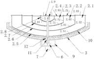
图1是本发明的飞行器多色喷墨打印装置的整体结构示意图(喷头朝下)。FIG. 1 is a schematic diagram of the overall structure of the aircraft multi-color inkjet printing device of the present invention (with the nozzle facing down).
图2是本发明中的喷墨打印装置的结构示意图。Fig. 2 is a schematic structural view of the inkjet printing device in the present invention.
图3是本发明中的喷墨打印装置的俯视结构示意图。FIG. 3 is a schematic top view of the inkjet printing device in the present invention.
图4是本发明的飞行器多色喷墨打印装置的整体结构示意图(喷头朝侧部)。Fig. 4 is a schematic diagram of the overall structure of the aircraft multi-color inkjet printing device of the present invention (the spray head faces to the side).
对于本领域普通技术人员来讲,在不付出创造性劳动的前提下,可以根据以上附图获得其他的相关附图。For those skilled in the art, other related drawings can be obtained according to the above drawings without any creative effort.
具体实施方式Detailed ways
为了使本技术领域的人员更好地理解本发明方案,下面结合具体实施例进一步说明本发明的技术方案。In order to enable those skilled in the art to better understand the solution of the present invention, the technical solution of the present invention will be further described below in conjunction with specific examples.
参见附图,一种飞行器多色喷墨打印装置,包括无人机本体1和设置在无人机本体上的喷墨打印装置。Referring to the accompanying drawings, an aircraft multi-color inkjet printing device includes a
所述喷墨打印装置包括墨盒单元2、墨盒基座3、气压供给单元4、供液管路单元5、电控阀组6和喷头7。The inkjet printing device includes an
所述墨盒基座3通过连接杆/连接架8安装在无人机本体1底部,墨盒单元2安装在墨盒基座3上。The
所述墨盒单元2具有四个独立的储液腔,分别是:第一储液腔2.1、第二储液腔2.1、第三储液腔2.3、第四储液腔2.4,所述第一储液腔的截面为U型,所述第二储液腔的截面为U型并且设置在第一储液腔围成的区域,所述第三储液腔的截面为U型并且设置在第二储液腔围成的区域,所述第四储液腔设置在第三储液腔围成的区域。The
具体的讲:所述第一储液腔2.1由第一碗型件2.5和第二碗型件2.6围合而成,第一碗型件2.5由第一圆弧底面2.51和连接在第一圆弧底面顶缘的第一圆筒侧壁2.52组成,第二碗型件2.6由第二圆弧底面2.61、连接在第二圆弧底面顶缘的第二圆筒侧壁2.62以及连接在第二圆筒侧壁顶缘的第一外翻平面2.63组成,第二碗型件口径小于第一碗型件口径(即第二碗型件的第二圆筒侧壁直径小于第一碗型件的第一圆筒侧壁直径)并且第二碗型件的第二圆筒侧壁高度小于第一碗型件的第一圆筒侧壁的高度,将第二碗型件设置在第一碗型件的内部,使第二碗型件的第一外翻平面2.63的外缘与第一碗型件的第一圆筒侧壁2.52的顶缘连接,从而第一碗型件和第二碗型件之间的空间形成截面为U型的第一储液腔2.1。Specifically: the first liquid storage chamber 2.1 is surrounded by a first bowl-shaped piece 2.5 and a second bowl-shaped piece 2.6, and the first bowl-shaped piece 2.5 is connected by a first arc bottom surface 2.51 and a first circle The first cylinder side wall 2.52 of the top edge of the arc bottom surface is made up of, and the second bowl 2.6 is made up of the second cylinder side wall 2.62 of the second arc bottom surface 2.61, the top edge of the second arc bottom surface, and the second cylinder side wall connected to the second arc bottom surface top edge. The first valgus plane 2.63 of the top edge of the cylinder side wall is formed, and the second bowl-shaped piece aperture is smaller than the first bowl-shaped piece aperture (that is, the second cylindrical sidewall diameter of the second bowl-shaped piece is smaller than that of the first bowl-shaped piece. diameter of the first cylinder sidewall) and the height of the second cylinder sidewall of the second bowl is less than the height of the first cylinder sidewall of the first bowl, the second bowl is arranged on the first bowl The inside of the piece, so that the outer edge of the first valgus plane 2.63 of the second bowl is connected with the top edge of the first cylindrical side wall 2.52 of the first bowl, so that the first bowl and the second bowl The space between the components forms the first liquid storage chamber 2.1 with a U-shaped cross section.
所述第二储液腔由第二碗型件2.6和第三碗型件2.7围合而成,第三碗型件2.7由第三圆弧底面2.71、连接在第三圆弧底面顶缘的第三圆筒侧壁2.72以及连接在第三圆筒侧壁顶缘的第二外翻平面2.73组成,第三碗型件口径小于第二碗型件口径(即第三碗型件的第三圆筒侧壁直径小于第二碗型件的第二圆筒侧壁直径)并且第三碗型件的第三圆筒侧壁高度小于第二碗型件的第二圆筒侧壁的高度,将第三碗型件设置在第二碗型件的内部,使第三碗型件的第二外翻平面2.73的外缘与第二碗型件的第二圆筒侧壁2.62的顶缘连接,从而第二碗型件和第三碗型件之间的空间形成截面为U型的第二储液腔2.2。The second liquid storage chamber is surrounded by the second bowl-shaped piece 2.6 and the third bowl-shaped piece 2.7, and the third bowl-shaped piece 2.7 is formed by the third arc bottom surface 2.71 connected to the top edge of the third arc bottom surface. The third cylindrical side wall 2.72 and the second valgus plane 2.73 that is connected to the top edge of the third cylindrical side wall are formed, and the third bowl-shaped piece caliber is smaller than the second bowl-shaped piece caliber (that is, the third bowl-shaped piece caliber) The cylinder sidewall diameter is less than the second cylinder sidewall diameter of the second bowl-shaped piece) and the third cylinder sidewall height of the third bowl-shaped piece is less than the height of the second cylinder sidewall of the second bowl-shaped piece, The third bowl is arranged inside the second bowl, and the outer edge of the second valgus plane 2.73 of the third bowl is connected with the top edge of the second cylindrical side wall 2.62 of the second bowl , so that the space between the second bowl and the third bowl forms a second liquid storage chamber 2.2 with a U-shaped section.
所述第三储液腔由第三碗型件2.7和第四碗型件2.8围合而成,第四碗型件2.8由第四圆弧底面2.81、连接在第四圆弧底面顶缘的第四圆筒侧壁2.82以及连接在第四圆筒侧壁顶缘的第三外翻平面2.83组成,第四碗型件口径小于第三碗型件口径(即第四碗型件的第四圆筒侧壁直径小于第三碗型件的第三圆筒侧壁直径)并且第四碗型件的第四圆筒侧壁高度小于第三碗型件的第三圆筒侧壁的高度,将第四碗型件设置在第三碗型件的内部,使第四碗型件的第三外翻平面2.83的外缘与第三碗型件的第三圆筒侧壁2.72的顶缘连接,从而第三碗型件和第四碗型件之间的空间形成截面为U型的第三储液腔2.3。The third liquid storage chamber is surrounded by the third bowl 2.7 and the fourth bowl 2.8, and the fourth bowl 2.8 is formed by the fourth arc bottom surface 2.81 connected to the top edge of the fourth arc bottom surface. The fourth cylinder side wall 2.82 and the third valgus plane 2.83 that is connected to the top edge of the fourth cylinder side wall are formed, and the fourth bowl-shaped piece diameter is smaller than the third bowl-shaped piece diameter (that is, the fourth diameter of the fourth bowl-shaped piece). cylinder sidewall diameter is less than the 3rd cylinder sidewall diameter of the 3rd bowl-shaped piece) and the 4th cylinder sidewall height of the 4th bowl-shaped piece is less than the height of the 3rd cylinder sidewall of the 3rd bowl-shaped piece, The fourth bowl is arranged inside the third bowl, so that the outer edge of the third valgus plane 2.83 of the fourth bowl is connected with the top edge of the third cylindrical side wall 2.72 of the third bowl , so that the space between the third bowl and the fourth bowl forms a third liquid storage cavity 2.3 with a U-shaped section.
所述第四储液腔由第四碗型件2.8和设置在第四碗型件顶部的顶盖2.9围合而成。The fourth liquid storage chamber is enclosed by a fourth bowl 2.8 and a top cover 2.9 arranged on the top of the fourth bowl.
所述供液管路单元5竖直穿装在墨盒单元2的中轴线位置,供液管路单元5包括4根供液管:第一供液管5.1、第二供液管5.2、第三供液管5.3和第四供液管5.4;第一供液管上设置有与第一储液腔连通的进液口,第二供液管上设置有与第二储液腔连通的进液口,第三供液管上设置有与第三储液腔连通的进液口,第四供液管上设置有与第四储液腔连通的进液口,从而使得各储液腔内的液体能够分别沿各自对应的供液管排出;进一步的说,第一供液管上的进液口位于第一储液腔底部位置,第二供液管上的进液口位于第二储液腔底部位置,第三供液管上的进液口位于第三储液腔底部位置,第四供液管上的进液口位于第四储液腔底部位置;进一步的说,4根供液管的长度相等,这样的目的是,保证供液管路单元的重心位置在墨盒单元的中轴线上(如果4根供液管的长度不一的话,那么会导致供液管路单元的重心位置与墨盒单元的中轴线偏离);进一步的说,在4根供液管贯穿各储液腔的碗型件位置设置密封件m,以保证各个储液腔之间的空间独立性,即,参见附图3,密封件m为圆片形状,4根供液管贯穿安装在该密封件上(即,在密封件上设置有4个用于安装供液管的通孔,所述供液管贯穿安装在通孔中,并且在通孔和供液管之间设置密封胶,保证密封性),并且在各储液腔的碗型件的中心位置开设用于安装该密封件的通孔,密封件密封安装在碗型件的中心位置。The liquid
在墨盒基座3的底部设置有支架9,所述电控阀组6和喷头7安装在该支架9上,电控阀组6包括4个电控阀:第一电控阀、第二电控阀、第三电控阀和第四电控阀,分别与供液管路单元的4根供液管的底部出液口通过软管11一一对应连接,用于控制4根供液管的导通状态,即第一供液管的底部出口通过第一软管与第一电控阀的进口连接,第二供液管的底部出口通过第二软管与第二电控阀的进口连接,第三供液管的底部出口通过第三软管与第三电控阀的进口连接,第四供液管的底部出口通过第四软管与第四电控阀的进口连接;所述4个电控阀的出口与喷头7连接,液体最终从喷头7中进行雾化喷出。A
所述气压供给单元4用于为墨盒单元的四个储液腔供给气压,从而当4根供液管的相应电控阀打开后,使对应的储液腔中的液体沿相应的供液管从喷头喷出。气压供给单元采用气泵,气泵设置在墨盒单元的顶部中心位置,使气泵的重心位于墨盒单元的中轴线上,气泵的出气口通过分支管路与墨盒单元的四个储液腔连通。The air pressure supply unit 4 is used to supply air pressure to the four liquid storage chambers of the ink cartridge unit, so that when the corresponding electric control valves of the four liquid supply pipes are opened, the liquid in the corresponding liquid storage chamber will flow along the corresponding liquid supply pipe. Spray from spray head. The air pressure supply unit adopts an air pump, and the air pump is arranged at the top center of the ink cartridge unit, so that the center of gravity of the air pump is located on the central axis of the ink cartridge unit, and the air outlet of the air pump communicates with the four liquid storage chambers of the ink cartridge unit through branch pipelines.
所述墨盒基座3的顶部为碗型,与墨盒单元底面弧度一致,在墨盒基座和墨盒单元底面之间设置有至少一圈滚珠10(墨盒基座顶面设置有用于安装滚珠的凹槽,该圈滚珠通过滚珠保持架安装在凹槽中);由于墨盒基座顶面和墨盒单元底面均为碗型(即圆弧底),并且二者之间设置了滚珠,因此,在无人机飞行过程中,当无人机机身发生偏斜时,在墨盒单元自身重力作用下,墨盒单元能够进行自适应调整,保持自身的平稳状态,从而有效减少或者避免墨盒单元内的液体晃动,对无人机的飞行稳定性造成影响。The top of the
进一步的说,在墨盒基座3上设置有用于所述软管穿过的通孔12,并且该通孔12的孔径要大于所有软管的直径之和,通过该通孔能够使4根供液管通过软管连接至相应的电控阀,并且由于采用了软管,因此能够使墨盒单元2在墨盒基座3上具有发生相对位移的能力(如果是供液管和电控阀直接连接的话,相当于是硬性一体连接结构,那么墨盒单元2和墨盒基座3之间不会发生相对位移,也就不能使墨盒单元2进行自适应调整,保持自身的平稳状态)。Further, the
进一步的说,在墨盒基座3上或者无人机本体上设置有支腿13,更进一步的说,支腿13的顶部为铰接安装,并且与微型电机传动连接,在无人机起飞后驱动支腿13收起。Furthermore, a
进一步的说,所述喷头7可以朝下设置(图1),用于对水平的承印面进行喷印;或者喷头也可以朝侧面设置(图4),此时需要在墨盒基座3底部设置横向的支撑杆14,将喷头7安装在支撑杆外端,从而使喷头的位置超过无人机本体的侧部,这样工作时,喷头能够对竖直的承印面进行喷印,并且无人机本体不会与承印面发生碰撞。进一步的说,在支撑杆的喷头的另一端设置配重15,使得支撑杆的重心位于墨盒单元的中轴线上。Further, the
工作时,墨盒单元2的四个储液腔中分别承装不同颜色的涂料/墨水,通过控制无人机的飞行轨迹和坐标并结合控制四个电控阀,来完成大面积、非平面、多色图案的喷印(喷印过程中,需要开启气压供给单元4,为墨盒单元的四个储液腔供给气压)。When working, the four liquid storage chambers of the
为了易于说明,实施例中使用了诸如“上”、“下”、“左”、“右”等空间相对术语,用于说明图中示出的一个元件或特征相对于另一个元件或特征的关系。应该理解的是,除了图中示出的方位之外,空间术语意在于包括装置在使用或操作中的不同方位。例如,如果图中的装置被倒置,被叙述为位于其他元件或特征“下”的元件将定位在其他元件或特征“上”。因此,示例性术语“下”可以包含上和下方位两者。装置可以以其他方式定位(旋转90度或位于其他方位),这里所用的空间相对说明可相应地解释。For ease of description, spatial relative terms such as "upper", "lower", "left", "right", etc. are used in the embodiments to describe the position of one element or feature shown in the figures relative to another element or feature. relation. It will be understood that the spatial terms are intended to encompass different orientations of the device in use or operation in addition to the orientation depicted in the figures. For example, if the device in the figures is turned over, elements described as "below" other elements or features would then be oriented "above" the other elements or features. Thus, the exemplary term "lower" can encompass both an orientation of above and below. The device may be otherwise oriented (rotated 90 degrees or at other orientations) and the spatially relative specifications used herein interpreted accordingly.
而且,诸如“第一”和“第二”等之类的关系术语仅仅用来将一个与另一个具有相同名称的部件区分开来,而不一定要求或者暗示这些部件之间存在任何这种实际的关系或者顺序。Moreover, relative terms such as "first" and "second", etc. are only used to distinguish one from another element having the same name, and do not necessarily require or imply any such actual existence between these elements. relationship or sequence.
以上对本发明做了示例性的描述,应该说明的是,在不脱离本发明的核心的情况下,任何简单的变形、修改或者其他本领域技术人员能够不花费创造性劳动的等同替换均落入本发明的保护范围。The present invention has been described as an example above, and it should be noted that, without departing from the core of the present invention, any simple deformation, modification or other equivalent replacements that can be made by those skilled in the art without creative labor all fall within the scope of this invention. protection scope of the invention.
Claims (10)
Priority Applications (1)
| Application Number | Priority Date | Filing Date | Title |
|---|---|---|---|
| CN202210760809.9ACN115008906B (en) | 2022-06-30 | 2022-06-30 | An aircraft multi-color inkjet printing device |
Applications Claiming Priority (1)
| Application Number | Priority Date | Filing Date | Title |
|---|---|---|---|
| CN202210760809.9ACN115008906B (en) | 2022-06-30 | 2022-06-30 | An aircraft multi-color inkjet printing device |
Publications (2)
| Publication Number | Publication Date |
|---|---|
| CN115008906A CN115008906A (en) | 2022-09-06 |
| CN115008906Btrue CN115008906B (en) | 2023-03-24 |
Family
ID=83078543
Family Applications (1)
| Application Number | Title | Priority Date | Filing Date |
|---|---|---|---|
| CN202210760809.9AExpired - Fee RelatedCN115008906B (en) | 2022-06-30 | 2022-06-30 | An aircraft multi-color inkjet printing device |
Country Status (1)
| Country | Link |
|---|---|
| CN (1) | CN115008906B (en) |
Families Citing this family (2)
| Publication number | Priority date | Publication date | Assignee | Title |
|---|---|---|---|---|
| CN116587608B (en)* | 2023-04-17 | 2024-03-29 | 南京航空航天大学 | Ink supply system and control method for sand mold additive manufacturing adhesive system |
| CN119872089A (en)* | 2024-12-13 | 2025-04-25 | 浙江省送变电工程有限公司 | Unmanned aerial vehicle marking mechanism for calibrating installation position of transmission line spacer and calibrating method |
Citations (8)
| Publication number | Priority date | Publication date | Assignee | Title |
|---|---|---|---|---|
| CN107264065A (en)* | 2016-04-08 | 2017-10-20 | 东芝泰格有限公司 | Printing equipment and printing process |
| CN109057349A (en)* | 2018-07-23 | 2018-12-21 | 王迅 | A kind of unmanned plane formula three-dimensional building printer |
| CN109113343A (en)* | 2018-08-10 | 2019-01-01 | 博湃建筑科技(上海)有限公司 | Build contoured machine and building Method of printing |
| CN110997334A (en)* | 2017-08-30 | 2020-04-10 | 理想科学工业株式会社 | printer |
| CN210706525U (en)* | 2019-07-22 | 2020-06-09 | 上海安悦节能技术有限公司 | A automatic yard device that spouts of unmanned aerial vehicle for photovoltaic fortune dimension |
| CN215424186U (en)* | 2020-12-22 | 2022-01-07 | 周国栋 | A steaming bowl assembly for easy steaming |
| CN215512871U (en)* | 2021-04-12 | 2022-01-14 | 李海祺 | Unmanned aerial vehicle carries on automatic air brushing device of type |
| CN114394239A (en)* | 2022-01-19 | 2022-04-26 | 胡国娣 | Adjustable digital printing equipment for manufacturing special-shaped advertising board |
Family Cites Families (1)
| Publication number | Priority date | Publication date | Assignee | Title |
|---|---|---|---|---|
| AUPQ056099A0 (en)* | 1999-05-25 | 1999-06-17 | Silverbrook Research Pty Ltd | A method and apparatus (pprint01) |
- 2022
- 2022-06-30CNCN202210760809.9Apatent/CN115008906B/ennot_activeExpired - Fee Related
Patent Citations (8)
| Publication number | Priority date | Publication date | Assignee | Title |
|---|---|---|---|---|
| CN107264065A (en)* | 2016-04-08 | 2017-10-20 | 东芝泰格有限公司 | Printing equipment and printing process |
| CN110997334A (en)* | 2017-08-30 | 2020-04-10 | 理想科学工业株式会社 | printer |
| CN109057349A (en)* | 2018-07-23 | 2018-12-21 | 王迅 | A kind of unmanned plane formula three-dimensional building printer |
| CN109113343A (en)* | 2018-08-10 | 2019-01-01 | 博湃建筑科技(上海)有限公司 | Build contoured machine and building Method of printing |
| CN210706525U (en)* | 2019-07-22 | 2020-06-09 | 上海安悦节能技术有限公司 | A automatic yard device that spouts of unmanned aerial vehicle for photovoltaic fortune dimension |
| CN215424186U (en)* | 2020-12-22 | 2022-01-07 | 周国栋 | A steaming bowl assembly for easy steaming |
| CN215512871U (en)* | 2021-04-12 | 2022-01-14 | 李海祺 | Unmanned aerial vehicle carries on automatic air brushing device of type |
| CN114394239A (en)* | 2022-01-19 | 2022-04-26 | 胡国娣 | Adjustable digital printing equipment for manufacturing special-shaped advertising board |
Also Published As
| Publication number | Publication date |
|---|---|
| CN115008906A (en) | 2022-09-06 |
Similar Documents
| Publication | Publication Date | Title |
|---|---|---|
| CN115008906B (en) | An aircraft multi-color inkjet printing device | |
| EP3415412B1 (en) | A surface cleaning device | |
| CN201127917Y (en) | Universal sprayer | |
| CN209832977U (en) | Reservoir, supply circuit for an ink jet printer and ink jet printer | |
| CN208018809U (en) | The Hydra sprayer of CMP tool chamber | |
| CN1392053A (en) | Ink tank with ink spill prevention | |
| CN105584217A (en) | Ceramic interior decoration 3D printer | |
| JP2011020115A (en) | Piezoelectric atomizer | |
| CN207118518U (en) | A kind of agricultural irrigation unmanned plane ejecting device | |
| CN216778660U (en) | Non-floating type aluminum paste dispersing device | |
| KR20090007612U (en) | Painting device with split paint container | |
| CN102320902B (en) | Internal-throttling rotary isopiestic granulating nozzle | |
| CN219482061U (en) | Dust fall sprayer for port construction | |
| CN215096409U (en) | Intelligent ink picking system for printing | |
| CN201211503Y (en) | Nozzle, dispensing member comprising the nozzle and dispenser comprising the dispensing member | |
| CN214354879U (en) | Spraying device capable of being locked in oriented mode and used for ink printing | |
| CN221341061U (en) | Unmanned aerial vehicle is sprayed to medicine | |
| CN105457779A (en) | Aerial fog dust suppression system | |
| CN212263706U (en) | Water spraying device | |
| CN217383962U (en) | Special atomizing device for spraying of glass fiber reinforced plastic cooling tower | |
| CN216440929U (en) | Spraying device | |
| CN213617390U (en) | Handicraft color spraying device | |
| CN212860836U (en) | Positive and negative pressure conversion device for printer nozzle | |
| CN209920771U (en) | Ink jet device for ink jet type digital printer based on corrugated board production | |
| CN220346205U (en) | Gas-adjusting type rock paint spraying device |
Legal Events
| Date | Code | Title | Description |
|---|---|---|---|
| PB01 | Publication | ||
| PB01 | Publication | ||
| SE01 | Entry into force of request for substantive examination | ||
| SE01 | Entry into force of request for substantive examination | ||
| GR01 | Patent grant | ||
| GR01 | Patent grant | ||
| CF01 | Termination of patent right due to non-payment of annual fee | Granted publication date:20230324 | |
| CF01 | Termination of patent right due to non-payment of annual fee |