CN115008392A - Fastening tool - Google Patents
Fastening toolDownload PDFInfo
- Publication number
- CN115008392A CN115008392ACN202210212163.0ACN202210212163ACN115008392ACN 115008392 ACN115008392 ACN 115008392ACN 202210212163 ACN202210212163 ACN 202210212163ACN 115008392 ACN115008392 ACN 115008392A
- Authority
- CN
- China
- Prior art keywords
- bit
- motor
- screw
- amount
- axial direction
- Prior art date
- Legal status (The legal status is an assumption and is not a legal conclusion. Google has not performed a legal analysis and makes no representation as to the accuracy of the status listed.)
- Pending
Links
- 238000002347injectionMethods0.000description23
- 239000007924injectionSubstances0.000description23
- 238000012986modificationMethods0.000description12
- 230000004048modificationEffects0.000description12
- 230000005540biological transmissionEffects0.000description10
- 238000000034methodMethods0.000description8
- 238000009434installationMethods0.000description6
- 238000003825pressingMethods0.000description5
- 239000003638chemical reducing agentSubstances0.000description4
- 238000002485combustion reactionMethods0.000description4
- 238000003780insertionMethods0.000description3
- 230000037431insertionEffects0.000description3
- 230000002159abnormal effectEffects0.000description2
- 210000000078clawAnatomy0.000description2
- 230000008878couplingEffects0.000description2
- 238000010168coupling processMethods0.000description2
- 238000005859coupling reactionMethods0.000description2
- 230000003247decreasing effectEffects0.000description2
- 238000010586diagramMethods0.000description2
- 239000002184metalSubstances0.000description2
- 238000003860storageMethods0.000description2
- 230000006835compressionEffects0.000description1
- 238000007906compressionMethods0.000description1
- 238000012790confirmationMethods0.000description1
- 238000005520cutting processMethods0.000description1
- 230000000694effectsEffects0.000description1
- 238000007689inspectionMethods0.000description1
- 238000012423maintenanceMethods0.000description1
- 238000005457optimizationMethods0.000description1
- 230000035515penetrationEffects0.000description1
- 239000000243solutionSubstances0.000description1
- 230000000007visual effectEffects0.000description1
- 238000004804windingMethods0.000description1
Images


Classifications
- B—PERFORMING OPERATIONS; TRANSPORTING
- B25—HAND TOOLS; PORTABLE POWER-DRIVEN TOOLS; MANIPULATORS
- B25B—TOOLS OR BENCH DEVICES NOT OTHERWISE PROVIDED FOR, FOR FASTENING, CONNECTING, DISENGAGING OR HOLDING
- B25B21/00—Portable power-driven screw or nut setting or loosening tools; Attachments for drilling apparatus serving the same purpose
- B25B21/002—Portable power-driven screw or nut setting or loosening tools; Attachments for drilling apparatus serving the same purpose for special purposes
- B—PERFORMING OPERATIONS; TRANSPORTING
- B23—MACHINE TOOLS; METAL-WORKING NOT OTHERWISE PROVIDED FOR
- B23P—METAL-WORKING NOT OTHERWISE PROVIDED FOR; COMBINED OPERATIONS; UNIVERSAL MACHINE TOOLS
- B23P19/00—Machines for simply fitting together or separating metal parts or objects, or metal and non-metal parts, whether or not involving some deformation; Tools or devices therefor so far as not provided for in other classes
- B23P19/04—Machines for simply fitting together or separating metal parts or objects, or metal and non-metal parts, whether or not involving some deformation; Tools or devices therefor so far as not provided for in other classes for assembling or disassembling parts
- B23P19/06—Screw or nut setting or loosening machines
- B—PERFORMING OPERATIONS; TRANSPORTING
- B25—HAND TOOLS; PORTABLE POWER-DRIVEN TOOLS; MANIPULATORS
- B25B—TOOLS OR BENCH DEVICES NOT OTHERWISE PROVIDED FOR, FOR FASTENING, CONNECTING, DISENGAGING OR HOLDING
- B25B21/00—Portable power-driven screw or nut setting or loosening tools; Attachments for drilling apparatus serving the same purpose
- B25B21/001—Combined nut setting and crimping
- B—PERFORMING OPERATIONS; TRANSPORTING
- B23—MACHINE TOOLS; METAL-WORKING NOT OTHERWISE PROVIDED FOR
- B23B—TURNING; BORING
- B23B31/00—Chucks; Expansion mandrels; Adaptations thereof for remote control
- B23B31/02—Chucks
- B23B31/10—Chucks characterised by the retaining or gripping devices or their immediate operating means
- B23B31/12—Chucks with simultaneously-acting jaws, whether or not also individually adjustable
- B—PERFORMING OPERATIONS; TRANSPORTING
- B25—HAND TOOLS; PORTABLE POWER-DRIVEN TOOLS; MANIPULATORS
- B25B—TOOLS OR BENCH DEVICES NOT OTHERWISE PROVIDED FOR, FOR FASTENING, CONNECTING, DISENGAGING OR HOLDING
- B25B21/00—Portable power-driven screw or nut setting or loosening tools; Attachments for drilling apparatus serving the same purpose
- B25B21/02—Portable power-driven screw or nut setting or loosening tools; Attachments for drilling apparatus serving the same purpose with means for imparting impact to screwdriver blade or nut socket
- B25B21/023—Portable power-driven screw or nut setting or loosening tools; Attachments for drilling apparatus serving the same purpose with means for imparting impact to screwdriver blade or nut socket for imparting an axial impact, e.g. for self-tapping screws
- B—PERFORMING OPERATIONS; TRANSPORTING
- B25—HAND TOOLS; PORTABLE POWER-DRIVEN TOOLS; MANIPULATORS
- B25B—TOOLS OR BENCH DEVICES NOT OTHERWISE PROVIDED FOR, FOR FASTENING, CONNECTING, DISENGAGING OR HOLDING
- B25B23/00—Details of, or accessories for, spanners, wrenches, screwdrivers
- B25B23/0007—Connections or joints between tool parts
- B—PERFORMING OPERATIONS; TRANSPORTING
- B25—HAND TOOLS; PORTABLE POWER-DRIVEN TOOLS; MANIPULATORS
- B25B—TOOLS OR BENCH DEVICES NOT OTHERWISE PROVIDED FOR, FOR FASTENING, CONNECTING, DISENGAGING OR HOLDING
- B25B23/00—Details of, or accessories for, spanners, wrenches, screwdrivers
- B25B23/0064—Means for adjusting screwing depth
- B—PERFORMING OPERATIONS; TRANSPORTING
- B25—HAND TOOLS; PORTABLE POWER-DRIVEN TOOLS; MANIPULATORS
- B25B—TOOLS OR BENCH DEVICES NOT OTHERWISE PROVIDED FOR, FOR FASTENING, CONNECTING, DISENGAGING OR HOLDING
- B25B23/00—Details of, or accessories for, spanners, wrenches, screwdrivers
- B25B23/02—Arrangements for handling screws or nuts
- B25B23/04—Arrangements for handling screws or nuts for feeding screws or nuts
- B25B23/045—Arrangements for handling screws or nuts for feeding screws or nuts using disposable strips or discs carrying the screws or nuts
- B—PERFORMING OPERATIONS; TRANSPORTING
- B25—HAND TOOLS; PORTABLE POWER-DRIVEN TOOLS; MANIPULATORS
- B25B—TOOLS OR BENCH DEVICES NOT OTHERWISE PROVIDED FOR, FOR FASTENING, CONNECTING, DISENGAGING OR HOLDING
- B25B23/00—Details of, or accessories for, spanners, wrenches, screwdrivers
- B25B23/02—Arrangements for handling screws or nuts
- B25B23/04—Arrangements for handling screws or nuts for feeding screws or nuts
- B25B23/06—Arrangements for handling screws or nuts for feeding screws or nuts using built-in magazine
- B—PERFORMING OPERATIONS; TRANSPORTING
- B25—HAND TOOLS; PORTABLE POWER-DRIVEN TOOLS; MANIPULATORS
- B25B—TOOLS OR BENCH DEVICES NOT OTHERWISE PROVIDED FOR, FOR FASTENING, CONNECTING, DISENGAGING OR HOLDING
- B25B27/00—Hand tools, specially adapted for fitting together or separating parts or objects whether or not involving some deformation, not otherwise provided for
- B25B27/0085—Hand tools, specially adapted for fitting together or separating parts or objects whether or not involving some deformation, not otherwise provided for explosive-powered
- B—PERFORMING OPERATIONS; TRANSPORTING
- B25—HAND TOOLS; PORTABLE POWER-DRIVEN TOOLS; MANIPULATORS
- B25B—TOOLS OR BENCH DEVICES NOT OTHERWISE PROVIDED FOR, FOR FASTENING, CONNECTING, DISENGAGING OR HOLDING
- B25B27/00—Hand tools, specially adapted for fitting together or separating parts or objects whether or not involving some deformation, not otherwise provided for
- B25B27/14—Hand tools, specially adapted for fitting together or separating parts or objects whether or not involving some deformation, not otherwise provided for for assembling objects other than by press fit or detaching same
- B—PERFORMING OPERATIONS; TRANSPORTING
- B25—HAND TOOLS; PORTABLE POWER-DRIVEN TOOLS; MANIPULATORS
- B25C—HAND-HELD NAILING OR STAPLING TOOLS; MANUALLY OPERATED PORTABLE STAPLING TOOLS
- B25C1/00—Hand-held nailing tools; Nail feeding devices
- B25C1/06—Hand-held nailing tools; Nail feeding devices operated by electric power
- B—PERFORMING OPERATIONS; TRANSPORTING
- B25—HAND TOOLS; PORTABLE POWER-DRIVEN TOOLS; MANIPULATORS
- B25F—COMBINATION OR MULTI-PURPOSE TOOLS NOT OTHERWISE PROVIDED FOR; DETAILS OR COMPONENTS OF PORTABLE POWER-DRIVEN TOOLS NOT PARTICULARLY RELATED TO THE OPERATIONS PERFORMED AND NOT OTHERWISE PROVIDED FOR
- B25F5/00—Details or components of portable power-driven tools not particularly related to the operations performed and not otherwise provided for
- B25F5/02—Construction of casings, bodies or handles
Landscapes
- Engineering & Computer Science (AREA)
- Mechanical Engineering (AREA)
- Details Of Spanners, Wrenches, And Screw Drivers And Accessories (AREA)
- Dental Tools And Instruments Or Auxiliary Dental Instruments (AREA)
- Portable Nailing Machines And Staplers (AREA)
Abstract
Translated fromChinese
Description
Translated fromChinese技术领域technical field
本发明涉及一种紧固工具,该紧固工具使螺丝批头与螺钉卡合,利用螺丝批头按压螺钉并向紧固对象物按压,使螺丝批头旋转并拧入。The invention relates to a tightening tool, which engages a screw bit with a screw, uses the screw bit to press the screw and presses the object to be tightened, and rotates the screw bit to screw it in.
背景技术Background technique
已知有利用从空气压缩机供给的压缩空气的空气压力或气体的燃烧压力将装填于钉仓的连结紧固件从打入器引导件的前端依次打出的被称为可移动式的打入机的工具。There is known a so-called portable type of driving in which the fastening fasteners loaded in the staple cartridge are sequentially driven from the front end of the driver guide by the air pressure of the compressed air supplied from the air compressor or the combustion pressure of the gas. machine tool.
作为利用气体的燃烧压力的打入机,有将小型的气瓶搭载于打入机主体而能够以无绳的方式使用的打入机,提出了使用螺钉作为被打入的连结紧固件的螺钉打入机(例如,参照专利文献1)。As a driver that utilizes the combustion pressure of gas, there is a driver in which a small gas cylinder is mounted on the driver main body and can be used without a cord, and a screw using a screw as a driver to be driven has been proposed. Driver (for example, refer to Patent Document 1).
另外,提出了利用使螺钉旋转的电动机的驱动力来压缩弹簧并利用弹簧的作用力来打入螺钉的螺钉打入机(例如,参照专利文献2)。Also, a screw driver has been proposed that compresses a spring by the driving force of a motor that rotates a screw, and drives the screw by the urging force of the spring (for example, refer to Patent Document 2).
在使用气体的燃烧压力或压缩空气的空气压力进行螺钉等的打入的打击系统的工具中,调整活塞的工作范围并不容易,因此提出了如下的打入深度调整装置,调整工具主体与打入对象物之间的距离来调整打入深度,能够调整与打入对象物抵接的推杆的高度(突出长度)(例如,参照专利文献3)。In the tool of the striking system that uses the combustion pressure of the gas or the air pressure of the compressed air to drive the screw, etc., it is not easy to adjust the working range of the piston. Therefore, the following driving depth adjustment device has been proposed to adjust the tool body and the hammer. The driving depth can be adjusted according to the distance between the driving objects, and the height (protrusion length) of the plunger in contact with the driving object can be adjusted (for example, refer to Patent Document 3).
另外,调整打入深度的调整机构与抵接于打入对象物的被称为推杆或接触臂的部件以机构的方式连结,因此需要配置在接触臂的附近,但提出了将该调整机构配置在机头部的侧面,能够防止接触臂的变形的接触臂引导机构(例如,参照专利文献4)。In addition, an adjustment mechanism for adjusting the driving depth is mechanically connected to a member called a push rod or a contact arm that is in contact with the driving target, so it needs to be arranged in the vicinity of the contact arm, but this adjustment mechanism has been proposed. A contact arm guide mechanism that is arranged on the side surface of the nose portion and can prevent deformation of the contact arm (for example, refer to Patent Document 4).
此外,提出了如下的驱动电动机的自动停止机构,在不具有螺丝批头的前进机构的螺钉紧固机中,具备在通过机头部的后退移动而螺钉到达预定的拧入深度时与调整杆和切换杆关联地使驱动电动机的启动开关进行断开工作的切换板,以机械的方式使开关断开,来使螺丝批头的旋转停止(例如,参照专利文献5)。In addition, an automatic stop mechanism for driving a motor is proposed, in a screw tightening machine not having a forward mechanism of a screwdriver bit, which is provided with an adjustment lever when the screw reaches a predetermined screwing depth by the backward movement of the head part. A switch plate that turns off the start switch of the drive motor in association with the switch lever mechanically turns off the switch to stop the rotation of the bit (for example, see Patent Document 5).
现有技术文献prior art literature
专利文献1:日本特许第5590505号Patent Document 1: Japanese Patent No. 5590505
专利文献2:日本特许第6197547号Patent Document 2: Japanese Patent No. 6197547
专利文献3:日本实开平3-47781号Patent Document 3: Japanese Patent Application No. Hei 3-47781
专利文献4:日本特开2002-346947号Patent Document 4: Japanese Patent Laid-Open No. 2002-346947
专利文献5:日本特开平7-266246号Patent Document 5: Japanese Patent Application Laid-Open No. 7-266246
发明内容SUMMARY OF THE INVENTION
发明所要解决的课题The problem to be solved by the invention
在能够以机械的方式调整接触臂的突出长度的结构中,部件数量增加,并且重量也增加。另外,能够调整接触臂的突出长度的范围较小,也无法提高调整的精度。此外,在使用气体的燃烧压力或压缩空气的空气压力进行螺钉等的打入的打击系统的工具中,由于通过橡胶等弹性部件限制使螺丝批头前进的活塞的前进位置,因此打入深度因环境温度和弹性部件的温度这样的外在因素而不稳定。另外,由于能够配置调整机构的部位限定于机头部的附近,因此工具的前端侧大型化。此外,由于配置操作调整机构的拨盘等的操作部的部位也限定于机头部的附近,因此不能说在深度调整的操作性方面能够最优化。In the structure in which the protruding length of the contact arm can be adjusted mechanically, the number of parts increases, and the weight also increases. In addition, the range in which the protruding length of the contact arm can be adjusted is small, and the accuracy of the adjustment cannot be improved. In addition, in the tool of the striking system that uses the combustion pressure of the gas or the air pressure of the compressed air to drive the screw, etc., since the advance position of the piston that advances the bit is restricted by the elastic member such as rubber, the depth of the drive depends on the It is unstable due to external factors such as ambient temperature and the temperature of elastic parts. In addition, since the position where the adjustment mechanism can be arranged is limited to the vicinity of the nose portion, the size of the distal end side of the tool is increased. In addition, since the site where the operation part such as the dial of the operation adjustment mechanism is arranged is also limited to the vicinity of the nose part, it cannot be said that the operability of the depth adjustment can be optimized.
本发明为了解决这样的课题而作出,其目的在于提供一种能够对螺丝批头的沿着轴向的移动量以电气方式进行控制的紧固工具。The present invention has been made in order to solve such a problem, and an object thereof is to provide a tightening tool that can electrically control the amount of movement of a bit in the axial direction.
用于解决课题的技术方案Technical solutions for solving problems
为了解决上述的课题,本发明是一种紧固工具,具备:批头保持部,具有对螺丝批头以能够旋转且能够在轴向上移动的方式进行保持的保持部件;第一驱动部,具有使由批头保持部保持于保持部件的螺丝批头旋转的第一电动机;第二驱动部,具有使螺丝批头沿着轴向移动的第二电动机;及控制部,通过第二电动机的旋转量来控制螺丝批头的沿着轴向的移动量。In order to solve the above-mentioned problems, the present invention provides a tightening tool including: a bit holding portion having a holding member that holds a screw bit rotatably and movably in the axial direction; and a first driving portion, There is a first motor for rotating the screw bit held by the bit holding part on the holding member; a second driving part has a second motor for moving the screw bit in the axial direction; and a control part through the second motor. The amount of rotation controls the amount of movement of the screwdriver bit along the axial direction.
在本发明中,由批头保持部保持于保持部件的螺丝批头通过第二电动机沿着轴向移动,沿着轴向的移动量由第二电动机的旋转量控制。In the present invention, the bit held on the holding member by the bit holding portion is moved in the axial direction by the second motor, and the amount of movement in the axial direction is controlled by the amount of rotation of the second motor.
发明效果Invention effect
在本发明中,能够通过使螺丝批头在轴向上移动的电动机的旋转量来控制螺丝批头的沿着轴向的移动量。由此,能够抑制机械部件数量的增加,还能够抑制重量的增加。另外,由于机械结构的调整机构未配置于机头部的附近,能够抑制工具的前端侧的大型化,因此螺钉的打入位置的目视确认变得容易。此外,能够扩大能够调整螺丝批头的沿着轴向的移动量的范围,还能够提高螺钉的打入深度的调整的精度。另外,由于不是通过橡胶等弹性部件来限制螺丝批头的前进位置的结构,因此能够抑制受到环境温度或弹性部件的温度这样的外在因素的影响,螺钉的打入深度稳定。此外,螺丝批头的沿着轴向的移动量的设定能够通过电信号进行,所以对设定移动量的单元的配置的制约较少,容易进行考虑了螺钉的打入深度调整的操作性的优化。In the present invention, the amount of movement of the bit in the axial direction can be controlled by the amount of rotation of the motor that moves the bit in the axial direction. Thereby, an increase in the number of mechanical parts can be suppressed, and an increase in weight can also be suppressed. Moreover, since the adjustment mechanism of a mechanical structure is not arrange|positioned in the vicinity of a machine head, the enlargement of the front-end side of a tool can be suppressed, and visual confirmation of the driving position of a screw becomes easy. In addition, the range in which the amount of movement of the bit in the axial direction can be adjusted can be expanded, and the accuracy of adjustment of the driving depth of the screw can be improved. In addition, since the forward position of the bit is not restricted by an elastic member such as rubber, the influence of external factors such as ambient temperature and the temperature of the elastic member can be suppressed, and the screw penetration depth can be stabilized. In addition, since the setting of the amount of movement of the bit in the axial direction can be performed by an electric signal, there is less restriction on the arrangement of the means for setting the amount of movement, and the operability in consideration of the adjustment of the driving depth of the screw can be easily performed. Optimization.
附图说明Description of drawings
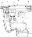
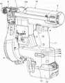
图1是表示本实施方式的紧固工具的内部结构的一例的侧剖视图。FIG. 1 is a side cross-sectional view showing an example of the internal structure of the fastening tool according to the present embodiment.
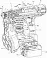
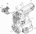
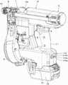
图2A是表示本实施方式的紧固工具的内部结构的一例的局部剖切立体图。2A is a partially cutaway perspective view showing an example of the internal structure of the fastening tool of the present embodiment.
图2B是表示本实施方式的紧固工具的内部结构的一例的局部剖切立体图。2B is a partially cutaway perspective view showing an example of the internal structure of the fastening tool of the present embodiment.
图2C是表示本实施方式的紧固工具的内部结构的一例的局部剖切立体图。2C is a partially cutaway perspective view showing an example of the internal structure of the fastening tool according to the present embodiment.
图3A是表示本实施方式的紧固工具的一例的侧视图。FIG. 3A is a side view showing an example of the fastening tool of the present embodiment.
图3B是表示本实施方式的紧固工具的一例的主视图。FIG. 3B is a front view showing an example of the fastening tool of the present embodiment.
图3C是表示本实施方式的紧固工具的一例的俯视图。FIG. 3C is a plan view showing an example of the fastening tool of the present embodiment.
图4A是表示本实施方式的紧固工具的一例的立体图。FIG. 4A is a perspective view showing an example of the fastening tool of the present embodiment.
图4B是表示本实施方式的紧固工具的一例的立体图。FIG. 4B is a perspective view showing an example of the fastening tool of the present embodiment.
图5是表示本实施方式的螺钉输送部的详细情况的立体图。FIG. 5 is a perspective view showing the details of the screw conveying unit of the present embodiment.
图6A是表示本实施方式的机头部的一例的立体图。FIG. 6A is a perspective view showing an example of the nose of the present embodiment.
图6B是表示本实施方式的机头部的一例的立体图。FIG. 6B is a perspective view showing an example of the nose of the present embodiment.
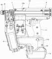
图7是表示本实施方式的紧固工具的动作的一例的侧剖视图。FIG. 7 is a side cross-sectional view showing an example of the operation of the fastening tool of the present embodiment.
图8A是表示本实施方式的紧固工具的动作的一例的局部剖切立体图。8A is a partially cutaway perspective view showing an example of the operation of the tightening tool of the present embodiment.
图8B是表示本实施方式的紧固工具的动作的一例的局部剖切立体图。8B is a partially cutaway perspective view showing an example of the operation of the fastening tool of the present embodiment.
图9A是表示本实施方式的紧固工具中的螺丝批头的拆装动作的一例的立体图。9A is a perspective view showing an example of a detaching and attaching operation of a bit in the tightening tool of the present embodiment.
图9B是表示本实施方式的紧固工具中的螺丝批头的拆装动作的一例的立体图。9B is a perspective view showing an example of the detachment and attachment operation of the bit in the tightening tool of the present embodiment.
图10A是表示本实施方式的紧固工具的变形例的侧剖视图。10A is a side cross-sectional view showing a modification of the fastening tool of the present embodiment.
图10B是表示本实施方式的紧固工具的其他变形例的侧剖视图。10B is a side cross-sectional view showing another modification of the fastening tool of the present embodiment.
图11是表示本实施方式的紧固工具的变形例的框图。FIG. 11 is a block diagram showing a modification of the fastening tool of the present embodiment.
图12A是表示螺钉的紧固状态的剖视图。12A is a cross-sectional view showing a tightened state of the screw.
图12B是表示螺钉的紧固状态的剖视图。12B is a cross-sectional view showing a tightened state of the screw.
图12C是表示螺钉的紧固状态的剖视图。12C is a cross-sectional view showing a tightened state of the screw.
图13是表示设定部的一例的俯视图。FIG. 13 is a plan view showing an example of a setting unit.
图14是表示本实施方式的变形例的紧固工具的动作例的流程图。FIG. 14 is a flowchart showing an example of the operation of the fastening tool according to the modification of the present embodiment.
图15A是表示设定部的设置位置的变形例的立体图。15A is a perspective view showing a modification of the installation position of the setting unit.
图15B是表示设定部的设置位置的变形例的立体图。15B is a perspective view showing a modification of the installation position of the setting unit.
图15C是表示设定部的设置位置的变形例的立体图。15C is a perspective view showing a modification of the installation position of the setting unit.
图15D是表示设定部的设置位置的变形例的立体图。15D is a perspective view showing a modification of the installation position of the setting unit.
具体实施方式Detailed ways
以下,参照附图对本发明的紧固工具的实施方式进行说明。Hereinafter, embodiments of the fastening tool of the present invention will be described with reference to the drawings.
<本实施方式的紧固工具的结构例><Configuration example of the fastening tool of the present embodiment>
图1是表示本实施方式的紧固工具的内部结构的一例的侧剖视图,图2A~图2C是表示本实施方式的紧固工具的内部结构的一例的局部剖切立体图。另外,图3A是表示本实施方式的紧固工具的一例的侧视图,图3B是表示本实施方式的紧固工具的一例的主视图,图3C是表示本实施方式的紧固工具的一例的俯视图。另外,图1中的切断面为图3B中的A-A线。此外,图4A~图4B是表示本实施方式的紧固工具的一例的立体图。1 is a side sectional view showing an example of the internal structure of the fastening tool according to the present embodiment, and FIGS. 2A to 2C are partially cutaway perspective views showing an example of the internal structure of the fastening tool according to the present embodiment. In addition, FIG. 3A is a side view showing an example of the fastening tool of the present embodiment, FIG. 3B is a front view showing an example of the fastening tool of the present embodiment, and FIG. 3C is a front view showing an example of the fastening tool of the present embodiment. Top view. In addition, the cut surface in FIG. 1 is the line A-A in FIG. 3B. 4A to 4B are perspective views showing an example of the fastening tool of the present embodiment.
本实施方式的紧固工具1具备工具主体10和手柄11。紧固工具1的手柄11在与在一个方向上延伸的工具主体10的延伸方向交叉的另一个方向上延伸。紧固工具1将工具主体10延伸的方向设为前后方向,将手柄11延伸的方向设为上下方向。另外,紧固工具1在手柄11的下部具备以可拆装的方式安装蓄电池12的蓄电池安装部13。The
紧固工具1具备:批头保持部3,对螺丝批头2以能够旋转且能够在沿着轴向的前后方向上移动的方式进行保持;第一驱动部4,使由批头保持部3保持的螺丝批头2旋转;及第二驱动部5,使由批头保持部3保持的螺丝批头2在沿着轴向的前后方向上移动。The
另外,紧固工具1具备:螺钉收纳部6,收纳螺钉200;螺钉输送部7,输送收纳于螺钉收纳部6的螺钉;及机头部8,被按压于紧固螺钉的紧固对象物,并且供螺钉射出。In addition, the
批头保持部3具备:保持部件30,对螺丝批头2以能够拆装的方式进行保持;旋转引导部件31,对保持部件30以能够在沿着螺丝批头2的轴向的前后方向上移动的方式进行支撑,并且与保持部件30一起旋转;移动部件32,使保持部件30沿着旋转引导部件31在前后方向上移动;及施力部件33,对移动部件32向后方向施力。The
保持部件30由外径比旋转引导部件31的内径稍小且进入旋转引导部件31的内侧的例如圆柱状的部件构成。保持部件30在沿着轴向的前侧的端部设置有与螺丝批头2的插入部20的截面形状一致的形状的开口30a。保持部件30在开口30a具备利用公知的机构对螺丝批头2的插入部20以可拆装的方式进行保持的机构。保持部件30的开口30a在旋转引导部件31的内侧露出,螺丝批头2的插入部20以能够拆装的方式插入开口30a。The holding
旋转引导部件31是沿着工具主体10的延伸方向延伸且保持部件30进入内侧的圆筒形状,前侧的端部经由轴承34a以能够旋转的方式支撑于在构成工具主体10的外装的树脂制的壳体10a的前侧设置的金属制的前框架10b。另外,旋转引导部件31的后侧的端部与第一驱动部4连结。The
旋转引导部件31的在沿着螺丝批头2的轴向的前后方向延伸的槽部31a形成于在径向上相向的侧部的两个部位。通过沿着径向贯通保持部件30并从保持部件30的两侧方突出的连结部件30b进入槽部31a,而旋转引导部件31经由连结部件30b而与保持部件30连结。
由此,当旋转引导部件31旋转时,连结部件30b被旋转引导部件31的槽部31a按压,从而保持部件30与旋转引导部件31一起旋转。另外,连结部件30b被旋转引导部件31的槽部31a引导,保持部件30在沿着螺丝批头2的轴向的前后方向上移动。Thereby, when the
移动部件32是传递部件的一例,具备:第一移动部件32a,与保持部件30一起旋转,使保持部件30沿着旋转引导部件31在前后方向上移动;第二移动部件32c,经由轴承32b而支撑于第一移动部件32a,利用轴承32b按压第一移动部件32a;及缓冲部件32d,安装于第二移动部件32c的后侧。The moving
第一移动部件32a由内径比旋转引导部件31的外径稍大且进入旋转引导部件31的外侧的例如圆筒状的部件构成。第一移动部件32a经由从旋转引导部件31的槽部31a突出的连结部件30b而与保持部件30连结。The first moving
轴承32b插入第一移动部件32a的外周与第二移动部件32c的内周之间,将第一移动部件32a支撑为能够相对于第二移动部件32c旋转。The
第二移动部件32c在向沿着轴向的前后方向的移动被限制的状态下,经由轴承32b而与第一移动部件32a连结。The second moving
由此,第一移动部件32a通过第二移动部件32c在沿着轴向的前后方向上移动的动作,经由轴承32b而被第二移动部件32c按压,与第二移动部件32c一起在沿着轴向的前后方向上移动。另外,第一移动部件32a能够相对于第二移动部件32c旋转。As a result, the first moving
在本例中,施力部件33由螺旋弹簧构成,在旋转引导部件31的外侧,进入设置于工具主体10的壳体10a的前侧的前框架10b与移动部件32的第二移动部件32c之间,与以与轴承32b的外圈的端面接触的方式配置的弹簧座抵接。施力部件33通过移动部件32向前方向移动而被压缩,对移动部件32施加向后方向按压移动部件32的力。In this example, the urging
第一驱动部4具备由从蓄电池12供给的电力驱动的批头旋转电动机40及减速机41。批头旋转电动机40是第一电动机的一例,批头旋转电动机40的轴40a与减速机41连结,减速机41的轴41a与旋转引导部件31连结。第一驱动部4是减速机41利用行星齿轮的结构,批头旋转电动机40与旋转引导部件31及由保持部件30保持的螺丝批头2配置在同轴上。The
第一驱动部4在设置于工具主体10的壳体10a的后侧的金属制的后框架10c安装有批头旋转电动机40及减速机41,减速机41的轴41a经由轴承42而支撑于后框架10c。The
批头保持部3和第一驱动部4通过前框架10b和后框架10c由在前后方向上延伸的结合部件10d连结,而组装成一体而单元化,并通过螺钉10e固定于工具主体10的壳体10a。批头保持部3和第一驱动部4构成为能够以各部件组装后的状态相对于工具主体10拆装,不是将各部件独立地固定于工具主体10的结构,组装性提高。The
另外,批头保持部3的旋转引导部件31的前侧的端部经由轴承34a而支撑于在工具主体10的壳体10a的前侧设置的前框架10b,旋转引导部件31的后侧的端部经由减速机41的轴41a及轴承42而支撑于在壳体10a的后侧设置的后框架10c。由此,批头保持部3的旋转引导部件31以能够旋转的方式支撑于工具主体10。In addition, the front end of the
由此,第一驱动部4通过批头旋转电动机40使旋转引导部件31旋转。当旋转引导部件31旋转时,连结部件30b被旋转引导部件31的槽部31a按压,从而保持螺丝批头2的保持部件30与旋转引导部件31一起旋转。Thereby, the
第二驱动部5具备由从蓄电池12供给的电力驱动的批头移动电动机50和减速机51。批头移动电动机50是电动机,是第二电动机的一例,批头移动电动机50的轴50a与减速机51连结,减速机51的轴51a与作为传递部件的一例的滑轮52连结。第二驱动部5的滑轮52经由轴承53而支撑于工具主体10。第二驱动部5的批头移动电动机50的轴50a沿着手柄11的延伸方向配置。The
第二驱动部5在滑轮52上卷绕有作为传递部件的一例的线材54,线材54与移动部件32的第二移动部件32c连结。In the
由此,第二驱动部5通过批头移动电动机50使滑轮52旋转,而卷绕线材54,由此使第二移动部件32c向前方向移动。批头保持部3通过第二移动部件32c向前方向移动,经由轴承32b按压第一移动部件32a,第一移动部件32a与第二移动部件32c一起向沿着轴向的前方向移动。通过第一移动部件32a向前方向移动,与第一移动部件32a经由连结部件30b而连结的保持部件30向前方向移动。Thereby, the
第二驱动部5相对于紧固工具1的左右方向上的大致中心向一侧偏移配置,以使滑轮52中卷绕线材54的部位的切线方向沿着旋转引导部件31的延伸方向。由此,滑轮52与第二移动部件32c之间的线材W以沿着移动部件32的移动方向的直线状延伸,抑制在滑轮52卷绕线材54时的负荷的增加、从滑轮52拉出线材W时的负荷的增加。The
第一驱动部4隔着手柄11而设置于工具主体10的一侧即后方。另外,第二驱动部5隔着手柄11而设置于工具主体10的另一侧即前方。The
螺钉收纳部6利用连结带连结多个螺钉200,收纳呈螺旋状地卷绕的连结螺钉。The screw
图5是表示本实施方式的螺钉输送部的详细情况的立体图。螺钉输送部7具备:螺钉输送电动机70;小齿轮71,安装于螺钉输送电动机70的轴;齿条72,与小齿轮71啮合;及卡合部73,与齿条72连结,并与从螺钉收纳部6输送的连结螺钉卡合。螺钉输送部7由小齿轮71及齿条72构成将螺钉输送电动机70的驱动力传递到卡合部73的螺钉输送传递部。卡合部73构成为经由形成有齿条72的部件而被未图示的压缩弹簧向上方施力,在未向螺钉输送电动机70供给电源的状态下,卡合部73及螺钉200不会因重量而下降。FIG. 5 is a perspective view showing the details of the screw conveying unit of the present embodiment. The
在螺钉输送部7中,螺钉输送电动机70固定于副框架74,并且齿条72以能够在沿着连结螺钉的输送方向的上下方向上移动的方式支撑于副框架74。螺钉输送部7的各部件通过爪等凹凸形状的嵌合、螺钉75的紧固等组装成一体而单元化。In the
图6A、图6B是表示本实施方式的机头部的一例的立体图。机头部8是第一机头部的一例,具备:射出通路构成部80a,由螺钉输送部7供给螺钉200,并且构成供螺丝批头2通过的射出通路80;接触部件81,具有与射出通路80连通的射出口81a,且与紧固对象物接触;接触臂82,与接触部件81联动地在前后方向上移动;及调整部83,限制接触臂82的移动量。另外,机头部8具备以能够开闭的方式覆盖从螺钉收纳部6到射出通路80的螺钉200所通过的路径的罩部件88。6A and 6B are perspective views showing an example of the nose portion of the present embodiment. The
如图2C所示,紧固工具1具备被接触臂82按压而工作的接触开关部84。另外,如图1A所示,紧固工具1在工具主体10具备机头主体部10f,在机头主体部10f具备通过与机头部8的射出通路构成部80a组合而构成射出通路80的射出通路构成部80b。机头主体部10f是第二机头部的一例,例如与前框架10b一体地构成。另外,机头主体部10f也可以是与前框架10b独立的部件固定于前框架10b的结构。As shown in FIG. 2C , the
机头部8以接触部件81能够在前后方向上移动的方式被支撑,接触臂82与接触部件81联动地在前后方向上移动。在机头部8中,接触部件81被未图示的施力部件向前方向施力,被按压于紧固对象物而向后方移动后的接触部件81被施力部件施力而向前方向移动。The
在机头部8中,接触部件81被按压于紧固对象物而接触臂82向后方移动,直至接触开关部84工作为止的接触臂82的移动量由调整部83调整。接触开关部84通过被接触臂82按压而切换是否工作,在本例中,将未被接触臂82按压而接触开关部84不工作的状态设为接触开关部84的断开,将被接触臂82按压而接触开关部84工作的状态设为接触开关部84的接通。In the
机头部8通过将构成射出通路80、接触部件81及接触臂82的各部件通过爪等凹凸形状的嵌合、螺钉85的紧固等一体地组装于副框架86而单元化,并通过螺钉87固定于构成工具主体10的前框架10b。当机头部8固定于前框架10b时,由固定于工具主体10侧的机头主体部10f的射出通路构成部80b和机头部8侧的部件即射出通路构成部80a构成射出通路80。The
具有将机头部8固定于工具主体10的功能的副框架86形成有构成射出通路80的一部分的射出通路构成部80a,还具有相对于工具主体10进行射出通路80的定位的功能。由此,当将机头部8固定于前框架10b时,射出通路构成部80a被正确地对位,即使将机头部8设为相对于工具主体10能够拆装的结构,也能够抑制射出通路80相对于螺丝批头2的移动路径尤其在径向上发生位置偏移。另外,接触开关部84安装于工具主体10侧,当将机头部8固定于前框架10b时,接触臂82的与接触开关部84相向的一侧的位置与接触开关部84一致。The
螺钉输送部7与前框架10b一体地构成或固定于前框架10,由此副框架74通过螺钉76固定于构成工具主体10的机头主体部10f。The
紧固工具1具备接受操作的扳机9、通过扳机9的操作而工作的扳机开关部90。扳机9设置于手柄11的前侧,构成为能够进行把持手柄11的手的出指操作。扳机开关部90被扳机9按压而工作。The
扳机开关部90通过被扳机9按压而切换是否工作,在本例中,将未操作扳机9且扳机开关部90未被扳机9按压而扳机开关部90不工作的状态设为扳机开关部90的断开,将扳机9被操作且扳机开关部90被扳机9按压而工作的状态设为扳机开关部90的接通。The
紧固工具1具备控制部100,控制部100基于通过扳机9的操作而工作的扳机开关部90及被接触部件81按压而工作的接触开关部84的输出来控制第一驱动部4、第二驱动部5及螺钉输送部7。在本例中,控制部100设置于在手柄11的下部设置的蓄电池安装部13的内部。The
<本实施方式的紧固工具的动作例><Example of operation of the tightening tool of the present embodiment>
图7是表示本实施方式的紧固工具的动作的一例的侧剖视图,图8A、图8B是表示本实施方式的紧固工具的动作的一例的局部剖切立体图,以下,参照各图来对本实施方式的紧固工具的紧固动作进行说明。7 is a side cross-sectional view showing an example of the operation of the fastening tool according to the present embodiment, and FIGS. 8A and 8B are partially cutaway perspective views showing an example of the operation of the fastening tool according to the present embodiment. The tightening operation of the tightening tool of the embodiment will be described.
如图1所示,紧固工具1在待机状态下,螺丝批头2的前端位于射出通路80的后方的待机位置P1,能够向射出通路80供给螺钉200。As shown in FIG. 1 , in the standby state of the
若接触部件81被按压于紧固对象物,接触开关部84被接触臂82按压而接触开关部84成为接通,扳机9被操作而扳机开关部90成为接通,则控制部100驱动第二驱动部5的批头移动电动机50,并且在预定的时机驱动第一驱动部4的批头旋转电动机40。When the
当批头移动电动机50被驱动而向作为一个方向的正方向旋转时,滑轮52向正方向旋转,由此线材54被卷绕于滑轮52。通过将线材54卷绕于滑轮52,而与线材54连结的第二移动部件32c被旋转引导部件31引导而向沿着轴向的前方向移动。当第二移动部件32c向前方向移动时,第一移动部件32a经由轴承32b而被第二移动部件32c按压,与第二移动部件32c一起压缩施力部件33并向沿着轴向的前方向移动。When the
当第一移动部件32a向前方向移动时,与第一移动部件32a通过连结部件30b连结的保持部件30的连结部件30b被旋转引导部件31的槽部31a引导,向沿着螺丝批头2的轴向的前方向移动。When the first moving
由此,保持于保持部件30的螺丝批头2向前方向移动,与被供给到机头部8的射出通路80的螺钉200卡合而使螺钉200向前方向移动并按压于紧固对象物。Thereby, the
当批头旋转电动机40被驱动而向作为一个方向的正方向旋转时,旋转引导部件31向正方向旋转。当旋转引导部件31向正方向旋转时,与保持部件30连结的连结部件30b被旋转引导部件31的槽部31a按压,从而保持部件30与旋转引导部件31一起旋转。When the
由此,保持于保持部件30的螺丝批头2使螺钉200向正方向(顺时针)旋转,并拧入紧固对象物。控制部100与利用第一驱动部4使螺丝批头2旋转而将螺钉拧入紧固对象物的动作联动地,基于施加于批头旋转电动机40的负荷、批头旋转电动机40的转速、施加于批头移动电动机50的负荷、批头移动电动机50的转速等,利用第一驱动部5使螺丝批头2向前方向移动,从而使螺丝批头2追随被拧入紧固对象物的螺钉。As a result, the
如图7所示,当螺丝批头2的前端从接触部件81的射出口81a突出并到达了预定的工作结束位置P2时,控制部100停止批头旋转电动机40的驱动,并且使批头移动电动机50反转。控制部100可以基于批头移动电动机50的转速来判断螺丝批头2的前端到达了工作结束位置P2,也可以基于施加于批头旋转电动机40的负荷、批头旋转电动机40的转速、施加于批头移动电动机50的负荷、批头移动电动机50的转速等使工作结束位置P2可变。As shown in FIG. 7 , when the front end of the
当批头移动电动机50向作为另一个方向的反方向旋转时,滑轮52向反方向旋转,由此线材54从滑轮52被拉出。通过将线材54从滑轮52拉出,而通过第二移动部件32c向前方向移动而被压缩的施力部件33伸长,将第二移动部件32c向后方向按压。When the
第二移动部件32c被施力部件33向后方向按压,从而被旋转引导部件31引导而向沿着轴向的后方向移动。当第二移动部件32c向后方向移动时,第一移动部件32a经由轴承32b而被第二移动部件32c牵引,与第二移动部件32c一起向沿着轴向的后方向移动。The second moving
当第一移动部件32a向后方向移动时,通过连结部件30b与第一移动部件32a连结的保持部件30的连结部件30b被旋转引导部件31的槽部31a引导,向沿着螺丝批头2的轴向的后方向移动。When the first moving
由此,保持于保持部件30的螺丝批头2向后方向移动,螺丝批头2的前端返回待机位置P1。另外,移动部件32通过在第二移动部件32c的后侧具备由橡胶等构成的缓冲部件32d,从而在第二移动部件32c向后方向移动的动作中,抑制第二移动部件32c直接与后框架10c接触,能够抑制声音的产生和损伤。当第二移动部件32c被施力部件33向后方向按压,螺丝批头2的前端返回到待机位置P1时,控制部100使批头移动电动机50的旋转停止。若扳机开关部90成为断开,则控制部100使螺钉输送电动机70向一个方向旋转,由此使卡合部73下降。当卡合部73下降到与下一个螺钉200卡合的位置时,控制部100通过使螺钉输送电动机70反转,使卡合部73上升,将下一个螺钉200供给到射出通路80。Thereby, the
紧固工具1具备:第一驱动部4,在设置于手柄11的蓄电池安装部13以能够拆装的方式安装有蓄电池12,利用由从该蓄电池12供给的电力驱动的批头旋转电动机40使螺丝批头2旋转;及第二驱动部5,利用由从蓄电池12供给的电力驱动的批头移动电动机50使螺丝批头2在沿着轴向的前后方向上移动。由此,不需要像由空气压力驱动的紧固工具那样连接软管,作业性提高。The
另外,紧固工具1通过具备使螺丝批头2在沿着轴向的前后方向上移动的第二驱动部5,从而在使接触部件81与紧固对象物抵接的状态下,能够在不使紧固工具1向接近紧固对象物的方向移动的情况下进行螺钉的紧固。由此,不需要如通常的钻孔机、冲击钻那样使工具主体向接近紧固对象物的方向移动的动作,作业性提高。In addition, since the
此外,第二驱动部5通过批头移动电动机50的驱动力将卡合于螺丝批头2的螺钉向紧固对象物按压,因此能够容易地进行将螺钉向紧固对象物按压的力的过量或不足的调整,能够以适当的力将螺钉向紧固对象物按压。In addition, the
另外,第一驱动部4隔着手柄11而设置于工具主体10的一侧即后方,第二驱动部5隔着手柄11而设置于工具主体10的另一侧即前方。由此,在夹着手柄11的前后,分别分散地配置具有电动机而重量比较重的第一驱动部4和第二驱动部5。因此,在用手把持手柄11并使工具主体10的延伸方向为大致水平的方向而进行紧固作业的情况下,夹着手柄11的前后的重量平衡变得大致均等,作业性提高。In addition, the
此外,第二驱动部5相对于紧固工具1的左右方向上的大致中心向一侧即左侧偏移配置,螺钉输送部7的螺钉输送电动机70相对于紧固工具1的左右方向上的大致中心向另一侧即右侧偏移配置。由此,左右的重量平衡也变得大致均等,作业性提高。In addition, the
如上所述,在紧固工具1中,使螺丝批头2旋转的第一驱动部4和使螺丝批头2在沿着轴向的前后方向上移动的第二驱动部5由独立的电动机驱动。由此,与由单一的驱动源进行两个动作的结构相比,不需要驱动力的传递机构和在预定的时机进行驱动力的传递的机构等,能够简化结构。另外,能够简化结构,从而能够实现轻量化。而且,能够通过控制来进行两个动作的联动。As described above, in the
另外,对于螺钉输送部7,通过将螺钉输送电动机70设为驱动源,也能够利用从蓄电池12供给的电力进行驱动,不需要空气压力的供给。此外,螺钉输送部7由与螺丝批头2的旋转和移动独立的电动机驱动,由此与利用单一的驱动源进行两个或三个动作的结构相比,能够简化结构。另外,能够通过控制来进行多个动作的联动。Moreover, the
螺钉输送部7构成为能够以各部件被单元化并组装的状态相对于构成工具主体10的机头主体部10f进行拆装。由此,不是将螺钉输送电动机70等各部件独立地固定于工具主体10的结构,组装性提高,也能够容易地进行保养、检修时的更换等。另外,与将各部件独立地固定于工具主体10的结构相比,能够提高各部件间的精度。此外,供螺钉输送部7固定的机头主体部10f与构成工具主体10的前框架10b一体或固定于前框架10b,因此能够提高螺钉输送部7相对于工具主体10的安装位置的精度。另外,因为机头主体部10f构成供螺丝批头2通过的射出通路80的一部分,所以能够提高螺钉输送部7相对于射出通路80的安装位置的精度。The screw conveyance
图9A、图9B是表示本实施方式的紧固工具中的螺丝批头的拆装动作的一例的立体图,接下来,参照各图对拆装螺丝批头2的动作进行说明。9A and 9B are perspective views showing an example of the operation of attaching and detaching the bit in the tightening tool of the present embodiment. Next, the operation of attaching and detaching the
如图1所示,在紧固工具1中,位于待机位置P1的螺丝批头2的前端位于机头部8的里侧,不向接触部件81的射出口81a露出。因此,在更换螺丝批头2的情况下,拆装机头部8。As shown in FIG. 1 , in the
关于机头部8的拆装,首先,拆下螺钉87。通过拆下螺钉87,如图9B所示,能够将机头部8从紧固工具1拆下。机头部8构成为能够在组装了各部件的状态下相对于工具主体10拆装,构成覆盖工具主体10的前侧的端部的接触部件81和射出通路80的部件等一体地被拆下。当机头部8从构成工具主体10的前框架10b被拆下时,作为机头部8侧的部件的射出通路构成部80a从固定于工具主体10侧的机头主体部10f的射出通路构成部80b被拆下,射出通路80露出。Regarding the attachment and detachment of the
由此,旋转引导部件31的前侧的端部在工具主体10的前侧的端部露出,螺丝批头2从旋转引导部件31的前侧的端部的开口露出。由此,通过利用扳手等工具抓住螺丝批头,并对其进行拉拽,能够将螺丝批头2从保持部件30拆下。Thereby, the front end of the
螺丝批头2的安装通过从旋转引导部件31的开口放入螺丝批头2并压入保持部件30的开口30a,而螺丝批头2被保持部件30保持。并且,将机头部8安装于工具主体10的前侧的端部,通过紧固螺钉87,将机头部8固定于工具主体10。The installation of the
另外,若是根据第二驱动部5的减速机51的减速比的关系,而在使批头移动电动机50停止的状态下,即使对滑轮52施加外力,滑轮52也不旋转的结构,则也可以设置在使移动部件33移动至使螺丝批头2的前端从旋转引导部件31突出预定量的更换位置的状态下使批头移动电动机50的旋转停止的批头更换模式。In addition, if the
机头部8构成为能够以构成射出通路80、接触部件81及接触臂82的各部件被单元化并组装的状态相对于工具主体10拆装。由此,不是将接触臂82等各部件独立地固定于工具主体10的结构,组装性提高。另外,与将各部件独立地固定于工具主体10的结构相比,能够提高各部件间的精度。此外,需要配线的接触开关部84安装于工具主体10侧,从而不需要配线的连接和切离。The
<本实施方式的紧固工具的变形例><Variation of the fastening tool of the present embodiment>
图10A是表示本实施方式的紧固工具的变形例的侧剖视图,图10B是表示本实施方式的紧固工具的其他变形例的侧剖视图,图11是表示本实施方式的紧固工具的变形例的框图。10A is a side cross-sectional view showing a modification of the fastening tool of the present embodiment, FIG. 10B is a side cross-sectional view showing another modification of the fastening tool of the present embodiment, and FIG. 11 is a modification of the fastening tool of the present embodiment. Example block diagram.
如上所述,紧固工具1为如下的结构,具备使螺丝批头2在沿着轴向的前后方向上移动的第二驱动部5,第二驱动部5由批头移动电动机50驱动,与由批头移动电动机50驱动而旋转的滑轮52通过线材54连结的移动部件32及与移动部件32连结的保持部件30沿着旋转引导部件31向沿着螺丝批头2的轴向的前方向移动。由此,能够通过控制批头移动电动机50的旋转量,来控制螺丝批头2的移动量(前进量)。即,通过与使螺丝批头2向紧固螺钉200的方向旋转的批头旋转电动机40的旋转联动地使批头移动电动机50旋转,能够利用批头移动电动机50的旋转量来控制随着螺钉200的紧固而追随螺钉200前进的螺丝批头2的前进量,从而控制螺丝批头2的沿着轴向的停止位置。As described above, the
图12A~图12C是表示螺钉的紧固状态的剖视图,图12A表示螺钉200的头部201不从紧固对象物202的表面浮起或埋入的所谓共面的状态,图12B表示螺钉200的头部201从紧固对象物202浮起的状态,图12C表示螺钉200的头部201埋入于紧固对象物202的状态。12A to 12C are cross-sectional views showing the tightened state of the screw. FIG. 12A shows a so-called coplanar state in which the
紧固工具1在螺丝批头2的前端到达工作结束位置P2时,在螺钉200为埋头螺钉的情况下,如图12A所示,优选以使螺钉200的头部201的表面成为与紧固对象物202的表面相同的所谓共面的状态的方式设定螺丝批头2的前进量。另外,螺钉200不限于埋头螺钉,如果是盘头螺钉、连接螺钉、桁架螺钉等,则优选以螺钉200的头部201的座面与紧固对象物202的表面接触而螺钉200的头部201不会成为从紧固对象物201浮起的状态的方式设定螺丝批头2的前进量。When the front end of the
在螺丝批头2的前端到达了工作结束位置P2时,在螺钉200的头部201如图12B所示那样处于从紧固对象物202浮起的状态的情况下,使螺丝批头2的前进量增加,使工作结束位置P2前进即可。另一方面,在螺钉200的头部201如图12C所示那样处于埋入于紧固对象物202的状态的情况下,使螺丝批头2的前进量减少,使工作结束位置P2后退即可。When the front end of the
因此,具备设定螺丝批头2的前进量的设定部110。设定部110是设定单元的一例,构成为能够选择多个设定值或者能够无级地选择任意的设定值。例如,如图10A所示,设定部110是通过旋转式的拨盘选择设定值的结构。Therefore, the setting
为了设定螺丝批头2的移动量(前进量),在设置专用的设定单元的方式中,在具备上述旋转式的拨盘的结构中,作为将作业者的操作转换为电信号的单元,可想到使用电阻值根据连接有拨盘的轴的旋转角度而变化的电位计、输出与旋转角度对应的脉冲的旋转编码器等的方式。控制部100读取它们的电压值或脉冲数,设定决定螺丝批头2的移动量(前进量)的批头移动电动机50的旋转次数(旋转量)。In order to set the movement amount (advance amount) of the
当被接触臂82按压而工作的接触开关部84和通过扳机9的操作而工作的扳机开关部90这两方接通,螺钉紧固开始的条件成立时,以螺丝批头2的初始位置即待机位置P1为起点,使批头移动电动机50旋转所设定的旋转量后,使其旋转停止或反转,由此能够控制工作结束位置P2而调整旋入深度。When both the
另外,如图10B所示,设定部110也可以是通过按钮选择设定值的结构。在使用按钮等通过按下而工作的开关的方式中,例如可想到使用多个、在本例中为两个轻触开关(瞬时开关)并根据被按下的开关来设定批头移动电动机50的旋转次数(旋转量)的方式。在该方式的情况下,若工具主体的电源被切断一次,则在下次电源接通时上次的设定值变得未知,因此也考虑使用EEPROM等存储元件来存储设定值。In addition, as shown in FIG. 10B , the
设定部110也可以是杆式的开关或触摸面板。另外,设定部110也可以组合多个设定单元,例如,也可以组合上述的拨盘方式和开关方式。在该情况下,也可以设为能够通过拨盘操作来调整旋入量并且在临时的角落打出等必须斜打的情况下能够通过开关的操作将旋入量设定得较深。The
此外,设定部110也可以具备通过标签或刻印等表示当前值的方法、通过LED等表示当前值的方法等来显示所选择的设定值的结构,以使作业者能够容易地掌握当前的设定值。另外,为了防止因噪声等引起的设定的误判断,也可以仅在批头移动电动机50停止时检测设定信号。另外,由于还可想到电位计因故障而表示通常的操作范围外的异常的电压,因此也可以想到不采用异常值或通过LED、蜂鸣器等向作业者通知发生了故障。In addition, the
在通过使止动件的位置移动等机械结构来调整螺丝批头2的前进量的结构中,也可以在机头部8的附近设置使止动件的位置移动的设定部。与此相对,在本实施方式的紧固工具1中,能够通过控制批头移动电动机50的旋转量,来对螺丝批头2的移动量(前进量)以电气方式进行控制。因此,设置设定部110的位置的制约较少。因此,在图10A、图10B的例子中,设定部110设置于在手柄11的下部设置的蓄电池安装部13的一方的侧部。另外,在用右手握持手柄11的情况下,设定部110用左手进行操作,因此设定部110可以设为设置于蓄电池安装部13的左侧的侧部的结构。In the structure in which the advance amount of the
图13是表示设定部的一例的俯视图。图13所示的设定部110是设置于图10B所示的紧固工具1的设定部110,具备选择使螺丝批头2的前进量阶段性地减少的设定值的按钮110a和选择使螺丝批头2的前进量阶段性地增加的设定值的按钮110b。FIG. 13 is a plan view showing an example of a setting unit. The
另外,设定部110为了能够在视觉上识别通过按钮110a的操作而选择的设定值,具备引导图110a1。引导图110a1可以设置于按钮110a,也可以设置于按钮110a的附近。相同地,设定部110为了能够在视觉上识别通过按钮110b的操作而选择的设定值,具备引导图110b1。引导图110b1可以设置于按钮110b,也可以设置于按钮110b的附近。In addition, the
此外,设定部110具备显示所选择的设定值的灯110c。灯110c是显示部的一例,根据多个灯110c点亮的数量来显示所选择的设定值。例如,在使螺丝批头2的前进量减少的情况下,减少点亮的灯110c的数量,在使螺丝批头2的前进量增加的情况下,增加点亮的灯110c的数量。另外,也可以是灯110c的颜色根据设定值而变更。Moreover, the setting
为了设定螺丝批头2的移动量(前进量),除了设置专用的设定单元的方式以外,作为设定单元,也可以使用接触开关部84和扳机开关部90。在将接触开关部84和扳机开关部90等现有的操作单元用作设定单元的方式中,通过对接触臂82和扳机9进行与执行通常的紧固动作的操作不同的预定的设定操作,能够设定批头移动电动机50的旋转次数(旋转量)。例如,若不使接触臂82工作而在预时机间内进行预定次数的扳动、放开扳机9的连续操作,则判断为是设定批头移动电动机50的旋转次数(旋转量)的设定操作。具体而言,可想到每当反复进行仅对扳机9快速地进行3次操作等的预定的操作时,阶段性地调整旋入深度。In order to set the movement amount (advance amount) of the
在将接触开关部84和扳机开关部90等现有的操作单元用作设定单元的方式中,不需要用于调整旋入量的其他操作单元和设定单元,因此能够使工具主体小型化、成本降低。In the case of using the existing operation means such as the
图14是表示本实施方式的变形例的紧固工具的动作例的流程图,接下来,参照各图,对设定螺丝批头2的前进量而进行紧固的动作进行说明。14 is a flowchart showing an example of the operation of the tightening tool according to the modification of the present embodiment. Next, the operation of setting the advance amount of the
控制部100在图14的步骤SA1中,基于由设定部110选择的设定值,设定规定螺丝批头2的前进量的批头移动电动机50的旋转量。当接触部件81被按压于紧固对象物,接触开关部84被接触臂82按压,在步骤SA2中接触开关部84成为接通,扳机9被操作,在步骤SA3中扳机开关部90成为接通时,控制部100在步骤SA4中驱动第二驱动部5的批头移动电动机50,并且在步骤SA5中驱动第一驱动部4的批头旋转电动机40。In step SA1 of FIG. 14 , the
当批头移动电动机50被驱动而向作为一个方向的正方向旋转时,与滑轮52通过线材54连结的移动部件32及与移动部件32连结的保持部件30沿着旋转引导部件31向沿着螺丝批头2的轴向的前方向移动。When the
由此,保持于保持部件30的螺丝批头2向前方向移动,与供给到机头部8的射出通路80的螺钉200卡合而使螺钉200向前方向移动并按压于紧固对象物。Thereby, the
另外,当批头旋转电动机40被驱动而向作为一个方向的正方向旋转时,保持部件30与旋转引导部件31一起旋转。In addition, when the
由此,保持于保持部件30的螺丝批头2使螺钉200向正方向(顺时针)旋转,并拧入紧固对象物。控制部100与利用第一驱动部4使螺丝批头2旋转而将螺钉拧入紧固对象物的动作联动地,基于施加于批头旋转电动机40的负荷、批头旋转电动机40的转速、施加于批头移动电动机50的负荷、批头移动电动机50的转速等,利用第一驱动部5使螺丝批头2向前方向移动,从而使螺丝批头2追随拧入紧固对象物的螺钉。As a result, the
当在步骤SA6中批头移动电动机50的旋转量成为由设定部110选择的设定值,螺丝批头2的前端到达所设定的工作结束位置P2时,控制部100在步骤SA7中停止批头旋转电动机40的驱动,并且在步骤SA8中使批头移动电动机50反转。When the rotation amount of the
当批头移动电动机50向作为另一个方向的反方向旋转时,线材54从滑轮52被拉出,从而移动部件32被施力部件33向后方向按压,移动部件32及与移动部件32连结的保持部件30沿着旋转引导部件31向沿着螺丝批头2的轴向的后方向移动。When the
控制部100在步骤SA9中,当直到线材54从滑轮52拉出预定量的初始位置,批头移动电动机50反转到初始位置时,在步骤SA10中停止批头移动电动机50的反转。The
由此,保持于保持部件30的螺丝批头2向后方向移动,螺丝批头2的前端返回到待机位置P1。Thereby, the
在紧固工具1中,能够通过控制批头移动电动机50的旋转量来控制螺丝批头2的移动量(前进量)。由此,与能够通过使止动件的位置移动等机械结构来调整螺丝批头2的前进量的结构相比,能够以简单的结构进行螺丝批头2的前端位置的高精度的调整。因此,能够抑制如图12B所示那样螺钉200的头部201从紧固对象物202浮起,或者如图12C所示那样螺钉200的头部201过度沉入紧固对象物202,如图12A所示,能够形成为所谓共面的状态,紧固作业后的成品美观。In the
图15A~图15D是表示设定部的设置位置的变形例的立体图。如上所述,在本实施方式的紧固工具1中,能够通过控制批头移动电动机50的旋转量来对螺丝批头2的移动量(前进量)以电气方式进行控制,因此设置设定部110的位置的制约较少。15A to 15D are perspective views showing modified examples of the installation positions of the setting parts. As described above, in the
因此,在图15A中,设定部110设置于在手柄11的下部设置的蓄电池安装部13的上部。另外,在图15B中,设定部110设置于蓄电池安装部13的后部。在蓄电池安装部13的上部或后部,通过在左右方向的中央附近设置设定部110,而无论握持手柄11的惯用手是哪个都能够进行设定部110的操作。Therefore, in FIG. 15A , the setting
此外,设定部110也可以设置于工具主体10侧,在图15C中,设定部110设置于工具主体10的侧部。在用右手握持手柄11的情况下,设定部110用左手进行操作,因此设定部110也可以设为设置于工具主体10的左侧的侧部的结构。In addition, the setting
另外,在图15D中,设定部110设置于工具主体10的后部,在本例中设置于覆盖第一驱动部4的罩部43的后部。在工具主体10的后部,通过在左右方向的中央附近设置设定部110,而无论握持手柄11的惯用手是哪个都能够进行设定部110的操作。另外,设定部110也可以设置于工具主体10的上部。In addition, in FIG. 15D, the setting
这样,能够通过电信号进行螺丝批头2的沿着轴向的移动量的设定,因此设定部110的配置的制约较少,容易进行考虑了旋入深度调整的操作性的优化。In this way, the amount of movement of the
附图标记说明Description of reference numerals
1···紧固工具,10···工具主体,10a···壳体,10b···前框架,10c···后框架,10d···结合部件,10e···螺钉,10f···机头主体部,11···手柄,12···蓄电池,13···蓄电池安装部,2···螺丝批头,3···批头保持部,30···保持部件,30a···开口,30b···连结部件,31···旋转引导部件,31a···槽部,32···移动部件(传递部件),32a···第一移动部件,32b···轴承,32c···第二移动部件,33···施力部件,4···第一驱动部,40···批头旋转电动机(第一电动机),40a···轴,41···减速机,41a···轴,42···轴承,5···第二驱动部,50···批头移动电动机(电动机、第二电动机),50a···轴,51···减速机,51a···轴,52···滑轮(传递部件),53···轴承,54···线材(传递部件),6···螺钉收纳部,7···螺钉输送部,70···螺钉输送电动机,71···小齿轮(螺钉输送传递部),72···齿条(螺钉输送传递部),73···卡合部,74···副框架,75、76···螺钉,8···机头部,80···射出通路,80a、80b···射出通路构成部,81···接触部件,81a···射出口,82···接触臂,83···调整部,84···接触开关部,85···螺钉,86···副框架,87···螺钉,88···罩部件,9···扳机,90···扳机开关部,100···控制部,110···设定部。1... Fastening tool, 10... Tool body, 10a... Housing, 10b... Front frame, 10c... Rear frame, 10d... Coupling member, 10e... Screw, 10f ...head body, 11...handle, 12...battery, 13...battery mounting portion, 2...screw bit, 3...bit holder, 30...holding member, 30a... opening, 30b...connecting member, 31...rotation guide member, 31a...groove portion, 32...moving member (transmission member), 32a...first moving member, 32b...bearing, 32c...second moving member, 33...forcer, 4...first driving part, 40...bit rotation motor (first motor), 40a... Shaft, 41...Reducer, 41a...Shaft, 42...Bearing, 5...Second drive unit, 50...Bit moving motor (motor, second motor), 50a... Shaft, 51...Reducer, 51a...Shaft, 52...Pulley (transmission member), 53...Bearing, 54...Wire rod (transmission member), 6...Screw storage, 7 ... screw conveying part, 70... screw conveying motor, 71... pinion (screw conveying transmission part), 72... rack (screw conveying transmission part), 73... engaging part, 74 ... sub-frame, 75, 76... screws, 8... nose, 80... ejection passage, 80a, 80b... ejection passage constituting portion, 81... contact member, 81a... ·Ejection port, 82...contact arm, 83...adjustment portion, 84...contact switch portion, 85...screw, 86...subframe, 87...screw, 88...cover Parts, 9...trigger, 90...trigger switch part, 100...control part, 110...setting part.
Claims (7)
Applications Claiming Priority (12)
| Application Number | Priority Date | Filing Date | Title |
|---|---|---|---|
| JP2021034725AJP7753645B2 (en) | 2021-03-04 | Fastening tool | |
| JP2021034723AJP7707579B2 (en) | 2021-03-04 | 2021-03-04 | Fastening tool |
| JP2021-034725 | 2021-03-04 | ||
| JP2021034722AJP7673427B2 (en) | 2021-03-04 | 2021-03-04 | Fastening Tools |
| JP2021034724AJP2022135118A (en) | 2021-03-04 | 2021-03-04 | fastening tool |
| JP2021-034723 | 2021-03-04 | ||
| JP2021-034724 | 2021-03-04 | ||
| JP2021-034722 | 2021-03-04 | ||
| JP2021-149654 | 2021-09-14 | ||
| JP2021149653AJP7703960B2 (en) | 2021-09-14 | 2021-09-14 | Fastening tool |
| JP2021149654AJP7700598B2 (en) | 2021-09-14 | 2021-09-14 | Fastening tool |
| JP2021-149653 | 2021-09-14 |
Publications (1)
| Publication Number | Publication Date |
|---|---|
| CN115008392Atrue CN115008392A (en) | 2022-09-06 |
Family
ID=80628456
Family Applications (6)
| Application Number | Title | Priority Date | Filing Date |
|---|---|---|---|
| CN202210213315.9APendingCN115008395A (en) | 2021-03-04 | 2022-03-04 | Fastening tool |
| CN202210213186.3APendingCN115008394A (en) | 2021-03-04 | 2022-03-04 | Fastening tool |
| CN202210212064.2APendingCN115091397A (en) | 2021-03-04 | 2022-03-04 | Fastening tool |
| CN202210212163.0APendingCN115008392A (en) | 2021-03-04 | 2022-03-04 | Fastening tool |
| CN202210212510.XAPendingCN115008393A (en) | 2021-03-04 | 2022-03-04 | Fastening tool |
| CN202210213540.2APendingCN115008396A (en) | 2021-03-04 | 2022-03-04 | Fastening tool |
Family Applications Before (3)
| Application Number | Title | Priority Date | Filing Date |
|---|---|---|---|
| CN202210213315.9APendingCN115008395A (en) | 2021-03-04 | 2022-03-04 | Fastening tool |
| CN202210213186.3APendingCN115008394A (en) | 2021-03-04 | 2022-03-04 | Fastening tool |
| CN202210212064.2APendingCN115091397A (en) | 2021-03-04 | 2022-03-04 | Fastening tool |
Family Applications After (2)
| Application Number | Title | Priority Date | Filing Date |
|---|---|---|---|
| CN202210212510.XAPendingCN115008393A (en) | 2021-03-04 | 2022-03-04 | Fastening tool |
| CN202210213540.2APendingCN115008396A (en) | 2021-03-04 | 2022-03-04 | Fastening tool |
Country Status (6)
| Country | Link |
|---|---|
| US (6) | US12214457B2 (en) |
| EP (7) | EP4052851A1 (en) |
| CN (6) | CN115008395A (en) |
| AU (4) | AU2022201520A1 (en) |
| ES (1) | ES2983016T3 (en) |
| TW (6) | TW202300257A (en) |
Families Citing this family (1)
| Publication number | Priority date | Publication date | Assignee | Title |
|---|---|---|---|---|
| TW202322984A (en)* | 2021-09-14 | 2023-06-16 | 日商美克司股份有限公司 | fastening tool |
Family Cites Families (83)
| Publication number | Priority date | Publication date | Assignee | Title |
|---|---|---|---|---|
| US3688966A (en) | 1969-11-10 | 1972-09-05 | Spotnails | Magazine and feed assembly for a fastener-driving tool |
| US3708097A (en) | 1971-03-18 | 1973-01-02 | Textron Inc | Nail feed mechanism |
| US3971421A (en) | 1974-02-26 | 1976-07-27 | Triad Fastener Corporation | Air-powered, self-feeding screw driving tool |
| US4367837A (en) | 1980-04-25 | 1983-01-11 | Manino Anthony P | Tape magazine feed apparatus for head driven fasteners |
| JPS59124579A (en)* | 1982-12-27 | 1984-07-18 | 室金属工業株式会社 | Continuous screw clamping machine |
| US4581964A (en) | 1985-02-22 | 1986-04-15 | Max Co. Ltd. | Fastener driving tool with improved magazine and feed mechanism |
| GB8704265D0 (en) | 1987-02-24 | 1987-04-01 | Yang T H | Manual electric tools(1) |
| JPS63300830A (en) | 1987-05-28 | 1988-12-08 | Nitto Seiko Co Ltd | Industrial robot screw tightening device |
| US4821937A (en) | 1987-09-14 | 1989-04-18 | Duo-Fast Corporation | Guide for fastener driving tool |
| JPH02232178A (en) | 1989-03-06 | 1990-09-14 | Masaki Kawashima | Fastener tightening machine |
| JPH0347781U (en) | 1989-09-14 | 1991-05-07 | ||
| DE3930999A1 (en) | 1989-09-16 | 1991-03-28 | Lorenz Stoeger | Screwdriver feed mechanism on robot - incorporates magazine for screws with mechanical conveyor to head |
| IT1248627B (en) | 1990-10-02 | 1995-01-21 | Umberto Monacelli | SCREWDRIVER FOR SCREWS CONNECTED BY A STRIP |
| US5144870A (en) | 1991-10-18 | 1992-09-08 | Nick Edward V | Apparatus for selectively installing fasteners |
| DE4334940C2 (en) | 1992-10-15 | 1996-10-31 | Max Co Ltd | Impact screw device |
| JP2894198B2 (en) | 1993-01-13 | 1999-05-24 | 株式会社デンソー | Screw fastening device |
| US5549169A (en) | 1993-01-13 | 1996-08-27 | Nippondenso Co., Ltd. | Screw tightening apparatus |
| DE4400709B4 (en) | 1993-01-13 | 2005-06-23 | Denso Corp., Kariya | Screw fastening device |
| JPH06312382A (en)* | 1993-04-28 | 1994-11-08 | Makita Corp | Drill bit storage structure for motor-driven tool |
| US5346453A (en) | 1993-08-12 | 1994-09-13 | Rivera Bottzeck Otto | Multiple bit power drill |
| JPH07241780A (en) | 1994-03-05 | 1995-09-19 | Muro Corp:Kk | Continuous machine screw fastening machine |
| JPH07266246A (en) | 1994-03-24 | 1995-10-17 | Max Co Ltd | Device for automatically stopping driving motor of thread fastener |
| EP0727284B1 (en) | 1995-02-15 | 2000-08-02 | Max Co., Ltd. | Screw driving machine with contact arm locking mechanism |
| JP3159016B2 (en)* | 1995-11-13 | 2001-04-23 | 株式会社ムロコーポレーション | Continuous screw tightening machine |
| EP1022096B1 (en) | 1995-11-20 | 2006-08-02 | Max Co., Ltd. | A screw guide mechanism of a screw driving and turning machine |
| AUPN741996A0 (en) | 1996-01-04 | 1996-01-25 | Interfix Limited | A driver |
| US5890405A (en) | 1996-09-11 | 1999-04-06 | Becker; Burkhard | Automated screw driving device |
| JP3405107B2 (en)* | 1997-01-31 | 2003-05-12 | マックス株式会社 | Pneumatic screw driving machine |
| JPH10235572A (en) | 1997-02-25 | 1998-09-08 | Matsushita Electric Works Ltd | Hand-held screw fastening machine |
| JPH10249750A (en)* | 1997-03-17 | 1998-09-22 | Muro Corp:Kk | Continuously machine screw fastening machine |
| JP2002239943A (en)* | 2001-02-14 | 2002-08-28 | Max Co Ltd | Fastener driver |
| JP2002346947A (en) | 2001-05-24 | 2002-12-04 | Max Co Ltd | Contact arm guide mechanism for nailer |
| JP3821005B2 (en)* | 2002-02-15 | 2006-09-13 | 日立工機株式会社 | Detachment device for driver bit of compressed air screw tightener |
| US20040006860A1 (en) | 2002-07-15 | 2004-01-15 | Haytayan Harry M. | Method and apparatus for attaching structural components with fasteners |
| DE20214489U1 (en) | 2002-09-19 | 2004-02-19 | Helfer & Co. Kg | Device for driving fasteners, in particular screws or the like. |
| US6655573B1 (en)* | 2002-11-18 | 2003-12-02 | Basso Industry Corp. | Screws dispensing device |
| JP2004249424A (en)* | 2003-02-21 | 2004-09-09 | Hitachi Koki Co Ltd | Connection screw tightening tool |
| JP4207700B2 (en)* | 2003-07-18 | 2009-01-14 | マックス株式会社 | Driving guide mechanism for nailing machine |
| US20050279517A1 (en) | 2004-06-21 | 2005-12-22 | Hoffman William H | Screw driving apparatus with attachable and detachable nose sub-assembly for use with single-feed screws or for use with automatic-feed collated screws |
| JP4802553B2 (en) | 2004-10-20 | 2011-10-26 | マックス株式会社 | Tar adhesion prevention mechanism for power driven nailers |
| US7055728B2 (en) | 2004-10-28 | 2006-06-06 | Basso Industry Corp. | Positioning structure for nailer |
| US6971567B1 (en) | 2004-10-29 | 2005-12-06 | Black & Decker Inc. | Electronic control of a cordless fastening tool |
| JP4577495B2 (en) | 2004-11-26 | 2010-11-10 | マックス株式会社 | Driving guide mechanism for screw and nail driving machines |
| US7225962B2 (en) | 2005-02-18 | 2007-06-05 | Illinois Tool Works Inc. | Nail advancement systems for nail arrays disposed within nailing tool magazines |
| DE102005000157B3 (en) | 2005-11-16 | 2007-04-05 | Hilti Ag | Manual nail gun, for driving nails or screws or bolts, has an electric drive to feed the fasteners into the chamber of the firing channel |
| TW200740569A (en) | 2006-04-24 | 2007-11-01 | Basso Ind Corp | Pushing flake structure of nail case |
| US7802500B2 (en)* | 2007-12-26 | 2010-09-28 | Illinois Tool Works, Inc. | Pneumatic fastener driving tool |
| TWI440530B (en)* | 2008-02-06 | 2014-06-11 | Max Co Ltd | Hand tool, nail residual detection mechanism, nail residual detection method, and power saving method |
| JP5262461B2 (en) | 2008-09-03 | 2013-08-14 | マックス株式会社 | Pneumatic screwing machine |
| TW201010829A (en) | 2008-09-08 | 2010-03-16 | Mobiletron Electronics Co Ltd | Automatic screw feeding apparatus for electricity powered screwdriver |
| JP5236606B2 (en)* | 2009-09-17 | 2013-07-17 | 三菱電機ビルテクノサービス株式会社 | Spanner equipment |
| JP5590505B2 (en) | 2009-09-30 | 2014-09-17 | 日立工機株式会社 | Driving machine |
| US8490516B2 (en) | 2009-09-30 | 2013-07-23 | Hitachi Koki Co., Ltd. | Screw driving machine having combustion-type power mechanism and electric power mechanism |
| US8894654B2 (en) | 2010-03-31 | 2014-11-25 | Smart Medical Devices, Inc. | Depth controllable and measurable medical driver devices and methods of use |
| DE102010030120A1 (en) | 2010-06-15 | 2011-12-15 | Hilti Aktiengesellschaft | driving- |
| DE102010063173A1 (en)* | 2010-12-15 | 2012-06-21 | Hilti Aktiengesellschaft | A bolt gun and method for operating a bolt gun |
| US8869656B2 (en)* | 2011-11-04 | 2014-10-28 | Senco Brands, Inc. | Screwdriver tool with improved corner fit function |
| EP3141351B1 (en) | 2012-01-13 | 2018-08-22 | Positec Power Tools (Suzhou) Co., Ltd | Power tool |
| TW201338936A (en) | 2012-03-28 | 2013-10-01 | Basso Ind Corp | Impact device of electrically-operated nail gun |
| TW201338933A (en)* | 2012-03-30 | 2013-10-01 | Basso Ind Corp | Electrical screw gun |
| DE102012206761A1 (en) | 2012-04-25 | 2013-10-31 | Hilti Aktiengesellschaft | Hand-held implement and method of operating a hand-held implement |
| TWI636856B (en) | 2013-07-04 | 2018-10-01 | 美克司股份有限公司 | Fastener tapping tool |
| JP6197547B2 (en)* | 2013-09-30 | 2017-09-20 | 日立工機株式会社 | Screwing machine |
| CN203680248U (en)* | 2013-11-28 | 2014-07-02 | 鸿富锦精密工业(深圳)有限公司 | Electric rotating tool |
| CN104972438B (en)* | 2014-04-10 | 2017-06-16 | 苏州宝时得电动工具有限公司 | Power tool |
| US20150306752A1 (en) | 2014-04-24 | 2015-10-29 | Basso Industry Corp. | Pneumatic nail gun |
| US20150336224A1 (en)* | 2014-05-26 | 2015-11-26 | Basso Industry Corp. | Anti-separating mechanism |
| JP6586777B2 (en) | 2015-05-27 | 2019-10-09 | 工機ホールディングス株式会社 | Driving machine |
| US10399193B2 (en) | 2017-01-25 | 2019-09-03 | The Boeing Company | Methods and apparatus to align threaded fasteners |
| CA2978391A1 (en) | 2017-09-07 | 2019-03-07 | Romp Coil Nail Industries Inc. | Staple advance device for stapler |
| JP6950423B2 (en) | 2017-09-29 | 2021-10-13 | マックス株式会社 | Driving tool |
| JP7144927B2 (en) | 2017-10-23 | 2022-09-30 | 株式会社マキタ | rotary tool |
| CN107914242A (en) | 2017-12-22 | 2018-04-17 | 王家宏 | Integral electric air pressure nailing gun |
| JP7231329B2 (en)* | 2018-02-19 | 2023-03-01 | 株式会社マキタ | screw tightening tool |
| JP2019155533A (en)* | 2018-03-13 | 2019-09-19 | 株式会社マキタ | Screw fastening tool |
| US10820911B2 (en) | 2018-05-17 | 2020-11-03 | Peninsula Surgical Solutions, Llc | Self-propelling surgical device |
| JP7035859B2 (en) | 2018-07-04 | 2022-03-15 | オムロン株式会社 | Screw tightening defect determination device, screw tightening system and program |
| JP6479248B1 (en) | 2018-12-11 | 2019-03-06 | 株式会社東日製作所 | Fastening device |
| US11273541B2 (en) | 2019-03-18 | 2022-03-15 | Kyocera Senco Industrial Tools, Inc. | Autofeed screwdriver attachment with twist collar to activate movable plates for latching to screw gun |
| JP7191751B2 (en)* | 2019-03-27 | 2022-12-19 | 株式会社マキタ | driving tool |
| WO2020195325A1 (en)* | 2019-03-27 | 2020-10-01 | オムロン株式会社 | Screw fastening failure determination device, screw fastening device, screw fastening failure determination method, and control program |
| JP7398894B2 (en)* | 2019-07-23 | 2023-12-15 | 株式会社マキタ | Tool holding device and electric working machine |
| CN110576405B (en) | 2019-08-15 | 2020-12-08 | 江西万上实业有限公司 | A screw gun for assembly |
- 2022
- 2022-03-04EPEP22160134.7Apatent/EP4052851A1/ennot_activeWithdrawn
- 2022-03-04USUS17/687,206patent/US12214457B2/enactiveActive
- 2022-03-04USUS17/687,447patent/US12186844B2/enactiveActive
- 2022-03-04CNCN202210213315.9Apatent/CN115008395A/enactivePending
- 2022-03-04ESES22160119Tpatent/ES2983016T3/enactiveActive
- 2022-03-04TWTW111107919Apatent/TW202300257A/enunknown
- 2022-03-04TWTW111107915Apatent/TW202300255A/enunknown
- 2022-03-04USUS17/686,981patent/US12186843B2/enactiveActive
- 2022-03-04CNCN202210213186.3Apatent/CN115008394A/enactivePending
- 2022-03-04EPEP22160138.8Apatent/EP4052852A1/enactivePending
- 2022-03-04CNCN202210212064.2Apatent/CN115091397A/enactivePending
- 2022-03-04EPEP22160119.8Apatent/EP4052848B1/enactiveActive
- 2022-03-04CNCN202210212163.0Apatent/CN115008392A/enactivePending
- 2022-03-04TWTW111107916Apatent/TW202302285A/enunknown
- 2022-03-04USUS17/687,099patent/US20220281088A1/ennot_activeAbandoned
- 2022-03-04TWTW111107922Apatent/TW202300259A/enunknown
- 2022-03-04CNCN202210212510.XApatent/CN115008393A/enactivePending
- 2022-03-04TWTW111107917Apatent/TW202300256A/enunknown
- 2022-03-04AUAU2022201520Apatent/AU2022201520A1/enactivePending
- 2022-03-04USUS17/687,033patent/US20220281084A1/enactivePending
- 2022-03-04EPEP24166431.7Apatent/EP4364893A3/enactivePending
- 2022-03-04CNCN202210213540.2Apatent/CN115008396A/enactivePending
- 2022-03-04AUAU2022201528Apatent/AU2022201528A1/enactivePending
- 2022-03-04USUS17/687,365patent/US20220281083A1/enactivePending
- 2022-03-04TWTW111107920Apatent/TW202300258A/enunknown
- 2022-03-04EPEP22160123.0Apatent/EP4052849A1/enactivePending
- 2022-03-04EPEP22160121.4Apatent/EP4104973B1/enactiveActive
- 2022-03-04EPEP22160125.5Apatent/EP4052850A1/enactivePending
- 2022-03-04AUAU2022201529Apatent/AU2022201529A1/enactivePending
- 2022-03-04AUAU2022201526Apatent/AU2022201526A1/enactivePending
Also Published As
Similar Documents
| Publication | Publication Date | Title |
|---|---|---|
| JP7490466B2 (en) | Fastening Tools | |
| CN110270956B (en) | Screw fastening tool | |
| CN115008392A (en) | Fastening tool | |
| JP7707579B2 (en) | Fastening tool | |
| JP7753645B2 (en) | Fastening tool | |
| JP7673427B2 (en) | Fastening Tools | |
| EP4286099A1 (en) | Fastening tool | |
| JP2022135119A (en) | fastening tool | |
| JP2022135118A (en) | fastening tool | |
| NZ785832A (en) | Fastening tool | |
| NZ785841A (en) | Fastening tool | |
| US20230330820A1 (en) | Fastening tool | |
| JP7700598B2 (en) | Fastening tool | |
| US12384008B2 (en) | Fastening tool | |
| JP7703960B2 (en) | Fastening tool |
Legal Events
| Date | Code | Title | Description |
|---|---|---|---|
| PB01 | Publication | ||
| PB01 | Publication | ||
| SE01 | Entry into force of request for substantive examination | ||
| SE01 | Entry into force of request for substantive examination |