CN115005986B - Individual intelligent navigation positioning device for single condyle replacement surgery and osteotome - Google Patents
Individual intelligent navigation positioning device for single condyle replacement surgery and osteotomeDownload PDFInfo
- Publication number
- CN115005986B CN115005986BCN202210616223.5ACN202210616223ACN115005986BCN 115005986 BCN115005986 BCN 115005986BCN 202210616223 ACN202210616223 ACN 202210616223ACN 115005986 BCN115005986 BCN 115005986B
- Authority
- CN
- China
- Prior art keywords
- osteotomy
- hole
- guide plate
- plate body
- positioning device
- Prior art date
- Legal status (The legal status is an assumption and is not a legal conclusion. Google has not performed a legal analysis and makes no representation as to the accuracy of the status listed.)
- Active
Links
- 238000001356surgical procedureMethods0.000titleclaimsabstractdescription68
- 210000002303tibiaAnatomy0.000claimsdescription29
- 210000001264anterior cruciate ligamentAnatomy0.000claimsdescription5
- 238000005516engineering processMethods0.000claimsdescription5
- 2380000101463D printingMethods0.000claimsdescription4
- 230000004083survival effectEffects0.000abstractdescription6
- 206010067268Post procedural infectionDiseases0.000abstractdescription5
- 208000004550Postoperative PainDiseases0.000abstractdescription3
- 238000000034methodMethods0.000description9
- 238000010586diagramMethods0.000description7
- 210000000988bone and boneAnatomy0.000description5
- 210000000629knee jointAnatomy0.000description5
- 238000009434installationMethods0.000description4
- 230000008569processEffects0.000description4
- 208000002193PainDiseases0.000description3
- 230000007794irritationEffects0.000description3
- 230000005499meniscusEffects0.000description3
- 210000004872soft tissueAnatomy0.000description3
- 238000011882arthroplastyMethods0.000description2
- 210000000845cartilageAnatomy0.000description2
- 208000014674injuryDiseases0.000description2
- 239000000463materialSubstances0.000description2
- 238000012986modificationMethods0.000description2
- 230000004048modificationEffects0.000description2
- 238000011084recoveryMethods0.000description2
- 125000006850spacer groupChemical group0.000description2
- 238000011883total knee arthroplastyMethods0.000description2
- 235000010893Bischofia javanicaNutrition0.000description1
- 240000005220Bischofia javanicaSpecies0.000description1
- 208000003947Knee OsteoarthritisDiseases0.000description1
- 206010033372Pain and discomfortDiseases0.000description1
- 208000027418Wounds and injuryDiseases0.000description1
- 210000000544articulatio talocruralisAnatomy0.000description1
- 230000009286beneficial effectEffects0.000description1
- 210000004439collateral ligamentAnatomy0.000description1
- 230000006378damageEffects0.000description1
- 230000007547defectEffects0.000description1
- 230000007850degenerationEffects0.000description1
- 210000003414extremityAnatomy0.000description1
- 210000003692iliumAnatomy0.000description1
- 239000007943implantSubstances0.000description1
- 230000006872improvementEffects0.000description1
- 208000015181infectious diseaseDiseases0.000description1
- 210000003127kneeAnatomy0.000description1
- 210000003041ligamentAnatomy0.000description1
- 238000004519manufacturing processMethods0.000description1
- 201000008482osteoarthritisDiseases0.000description1
- 210000000426patellar ligamentAnatomy0.000description1
- 210000002967posterior cruciate ligamentAnatomy0.000description1
- 230000002980postoperative effectEffects0.000description1
- 230000001568sexual effectEffects0.000description1
- 239000000725suspensionSubstances0.000description1
- 210000003906tibiofibular jointAnatomy0.000description1
- 230000008733traumaEffects0.000description1
- 210000000689upper legAnatomy0.000description1
Images


Classifications
- A—HUMAN NECESSITIES
- A61—MEDICAL OR VETERINARY SCIENCE; HYGIENE
- A61B—DIAGNOSIS; SURGERY; IDENTIFICATION
- A61B34/00—Computer-aided surgery; Manipulators or robots specially adapted for use in surgery
- A61B34/20—Surgical navigation systems; Devices for tracking or guiding surgical instruments, e.g. for frameless stereotaxis
- A—HUMAN NECESSITIES
- A61—MEDICAL OR VETERINARY SCIENCE; HYGIENE
- A61B—DIAGNOSIS; SURGERY; IDENTIFICATION
- A61B17/00—Surgical instruments, devices or methods
- A61B17/14—Surgical saws
- A61B17/142—Surgical saws with reciprocating saw blades, e.g. with cutting edges at the distal end of the saw blades
- A—HUMAN NECESSITIES
- A61—MEDICAL OR VETERINARY SCIENCE; HYGIENE
- A61B—DIAGNOSIS; SURGERY; IDENTIFICATION
- A61B17/00—Surgical instruments, devices or methods
- A61B17/14—Surgical saws
- A61B17/15—Guides therefor
- A61B17/154—Guides therefor for preparing bone for knee prosthesis
- A61B17/155—Cutting femur
- A—HUMAN NECESSITIES
- A61—MEDICAL OR VETERINARY SCIENCE; HYGIENE
- A61B—DIAGNOSIS; SURGERY; IDENTIFICATION
- A61B17/00—Surgical instruments, devices or methods
- A61B17/14—Surgical saws
- A61B17/15—Guides therefor
- A61B17/154—Guides therefor for preparing bone for knee prosthesis
- A61B17/157—Cutting tibia
- A—HUMAN NECESSITIES
- A61—MEDICAL OR VETERINARY SCIENCE; HYGIENE
- A61F—FILTERS IMPLANTABLE INTO BLOOD VESSELS; PROSTHESES; DEVICES PROVIDING PATENCY TO, OR PREVENTING COLLAPSING OF, TUBULAR STRUCTURES OF THE BODY, e.g. STENTS; ORTHOPAEDIC, NURSING OR CONTRACEPTIVE DEVICES; FOMENTATION; TREATMENT OR PROTECTION OF EYES OR EARS; BANDAGES, DRESSINGS OR ABSORBENT PADS; FIRST-AID KITS
- A61F2/00—Filters implantable into blood vessels; Prostheses, i.e. artificial substitutes or replacements for parts of the body; Appliances for connecting them with the body; Devices providing patency to, or preventing collapsing of, tubular structures of the body, e.g. stents
- A61F2/02—Prostheses implantable into the body
- A61F2/30—Joints
- A61F2/46—Special tools for implanting artificial joints
- A61F2/4603—Special tools for implanting artificial joints for insertion or extraction of endoprosthetic joints or of accessories thereof
- A61F2/461—Special tools for implanting artificial joints for insertion or extraction of endoprosthetic joints or of accessories thereof of knees
- A—HUMAN NECESSITIES
- A61—MEDICAL OR VETERINARY SCIENCE; HYGIENE
- A61F—FILTERS IMPLANTABLE INTO BLOOD VESSELS; PROSTHESES; DEVICES PROVIDING PATENCY TO, OR PREVENTING COLLAPSING OF, TUBULAR STRUCTURES OF THE BODY, e.g. STENTS; ORTHOPAEDIC, NURSING OR CONTRACEPTIVE DEVICES; FOMENTATION; TREATMENT OR PROTECTION OF EYES OR EARS; BANDAGES, DRESSINGS OR ABSORBENT PADS; FIRST-AID KITS
- A61F2/00—Filters implantable into blood vessels; Prostheses, i.e. artificial substitutes or replacements for parts of the body; Appliances for connecting them with the body; Devices providing patency to, or preventing collapsing of, tubular structures of the body, e.g. stents
- A61F2/02—Prostheses implantable into the body
- A61F2/30—Joints
- A61F2/46—Special tools for implanting artificial joints
- A61F2002/4687—Mechanical guides for implantation instruments
- Y—GENERAL TAGGING OF NEW TECHNOLOGICAL DEVELOPMENTS; GENERAL TAGGING OF CROSS-SECTIONAL TECHNOLOGIES SPANNING OVER SEVERAL SECTIONS OF THE IPC; TECHNICAL SUBJECTS COVERED BY FORMER USPC CROSS-REFERENCE ART COLLECTIONS [XRACs] AND DIGESTS
- Y02—TECHNOLOGIES OR APPLICATIONS FOR MITIGATION OR ADAPTATION AGAINST CLIMATE CHANGE
- Y02A—TECHNOLOGIES FOR ADAPTATION TO CLIMATE CHANGE
- Y02A50/00—TECHNOLOGIES FOR ADAPTATION TO CLIMATE CHANGE in human health protection, e.g. against extreme weather
- Y02A50/30—Against vector-borne diseases, e.g. mosquito-borne, fly-borne, tick-borne or waterborne diseases whose impact is exacerbated by climate change
Landscapes
- Health & Medical Sciences (AREA)
- Life Sciences & Earth Sciences (AREA)
- Surgery (AREA)
- Engineering & Computer Science (AREA)
- Animal Behavior & Ethology (AREA)
- General Health & Medical Sciences (AREA)
- Biomedical Technology (AREA)
- Heart & Thoracic Surgery (AREA)
- Veterinary Medicine (AREA)
- Public Health (AREA)
- Molecular Biology (AREA)
- Nuclear Medicine, Radiotherapy & Molecular Imaging (AREA)
- Medical Informatics (AREA)
- Orthopedic Medicine & Surgery (AREA)
- Transplantation (AREA)
- Oral & Maxillofacial Surgery (AREA)
- Physical Education & Sports Medicine (AREA)
- Dentistry (AREA)
- Robotics (AREA)
- Cardiology (AREA)
- Vascular Medicine (AREA)
- Surgical Instruments (AREA)
- Prostheses (AREA)
Abstract
Translated fromChinese
Description
Translated fromChinese技术领域technical field
本发明涉及外科器械技术领域,尤其涉及一种单髁置换手术个性化智能导航定位装置及截骨器。The invention relates to the technical field of surgical instruments, in particular to a personalized intelligent navigation and positioning device and an osteotomy device for unicondylar replacement surgery.
背景技术Background technique
全膝关节置换术是治疗终末期膝关节骨关节炎的有效方法,但是对单纯一侧胫股关节间室退变严重而对侧间室无任何疼痛不适的病例,有学者推荐膝关节单髁置换术,其目的是替换胫股关节受破坏的软骨表面。与胫骨高位截骨及全膝关节置换术相比,单髁置换术具有创伤小、恢复快、费用少以及对翻修影响小等优势。Total knee arthroplasty is an effective method for the treatment of end-stage knee osteoarthritis, but for cases with severe degeneration of the tibiofemoral compartment on one side without any pain and discomfort in the opposite compartment, some scholars recommend unicondylar knee joint Replacement surgery, the purpose of which is to replace the damaged cartilage surface of the tibiofemoral joint. Compared with high tibial osteotomy and total knee arthroplasty, unicompartmental arthroplasty has the advantages of less trauma, faster recovery, less cost, and less impact on revision.
由于早期假体工艺及设计方面的缺陷,单髁置换术很长一段时间不被临床所接受。近几年,随着手术技术、假体设计的改进及手术指征的明确,单髁置换术的应用获得了良好的近期疗效。但单髁置换术在假体安放和力线方面并无统一标准,而假体植入位置不准确是影响假体生存率非常重要的影响因素。Due to defects in early prosthesis technology and design, unicompartmental replacement was not accepted clinically for a long time. In recent years, with the improvement of surgical techniques, prosthesis design and clear surgical indications, the application of unicompartmental replacement has achieved good short-term results. However, there is no uniform standard for prosthesis placement and alignment in unicompartmental replacement, and inaccurate implant placement is a very important factor affecting the survival rate of the prosthesis.
传统的关节置换术主要依靠截骨导板配合机械对线系统完成截骨、假体安放和肢体力线控制,其精确性在很大程度上依赖于术者的经验,需凭借手术医生的经验和手感定位解剖标志,存在主观误差,因此,亟需一种单髁置换手术个性化智能导航定位装置及截骨器,来准确的确定截骨方向,确保截骨精度。The traditional arthroplasty mainly relies on the osteotomy guide plate combined with the mechanical alignment system to complete the osteotomy, prosthesis placement and limb line control. There are subjective errors in locating anatomical landmarks by hand. Therefore, there is an urgent need for a personalized intelligent navigation positioning device and osteotomy device for unicondylar replacement surgery to accurately determine the direction of osteotomy and ensure the accuracy of osteotomy.
发明内容Contents of the invention
本发明提供一种单髁置换手术个性化智能导航定位装置及截骨器,用以解决现有单髁置换手术个性化智能导航定位装置难以确定截骨方向的技术问题,提高手术的成功率和假体的生存率。The invention provides a personalized intelligent navigation and positioning device and an osteotomy device for unicondylar replacement surgery, which is used to solve the technical problem that the existing personalized intelligent navigation and positioning device for unicondylar replacement surgery is difficult to determine the direction of osteotomy, and improve the success rate of surgery and Prosthetic survival.
本发明提供一种单髁置换手术个性化智能导航定位装置,包括:导板本体,所述导板本体设有截骨槽和截面呈长方形的通孔,所述截骨槽的深度方向与所述通孔的高度方向相同,所述截骨槽的长度方向与所述通孔的深度方向相同,所述截骨槽的槽底高于所述通孔的顶部,所述截骨槽的截骨开口方向朝向所述导板本体的顶部;The invention provides a personalized intelligent navigation and positioning device for unicondylar replacement surgery, comprising: a guide plate body, the guide plate body is provided with an osteotomy groove and a through hole with a rectangular cross section, the depth direction of the osteotomy groove is in line with the through hole The height direction of the hole is the same, the length direction of the osteotomy groove is the same as the depth direction of the through hole, the bottom of the osteotomy groove is higher than the top of the through hole, and the osteotomy opening of the osteotomy groove is direction towards the top of the fence body;
其中,所述截骨槽的截骨开口在屈曲位时指向髂前上嵴。Wherein, the osteotomy opening of the osteotomy groove points to the anterior superior iliac crest in a flexed position.
根据本发明提供一种的单髁置换手术个性化智能导航定位装置,所述通孔的第一侧壁在所述通孔高度方向的投影位于所述截骨槽的第二侧壁和第三侧壁在所述截骨槽深度方向的投影区域之间。According to the present invention provides a personalized intelligent navigation and positioning device for unicompartmental replacement surgery, the projection of the first side wall of the through hole in the height direction of the through hole is located at the second side wall and the third side wall of the osteotomy groove. The side walls are between the projection areas in the depth direction of the osteotomy groove.
根据本发明提供的一种单髁置换手术个性化智能导航定位装置,所述导板本体用于与所述胫骨相连的一侧为拟合连接侧;According to a personalized intelligent navigation and positioning device for unicondylar replacement surgery provided by the present invention, the side of the guide plate body used to connect with the tibia is the fitting connection side;
所述拟合连接侧在第一高度位置设有第一拟合部和第二拟合部,所述第一拟合部和所述第二拟合部之间形成所述截骨槽;The fitting connection side is provided with a first fitting part and a second fitting part at a first height position, and the osteotomy groove is formed between the first fitting part and the second fitting part;
所述拟合连接侧在第二高度位置设有第三拟合部。The fitting connection side is provided with a third fitting portion at the second height position.
根据本发明提供的一种单髁置换手术个性化智能导航定位装置,所述第一拟合部的长度大于所述第二拟合部的长度,所述第一拟合部用于延伸至前交叉韧带内侧。According to a personalized intelligent navigation and positioning device for unicondylar replacement surgery provided by the present invention, the length of the first fitting part is greater than the length of the second fitting part, and the first fitting part is used to extend to the front Inside the cruciate ligament.
根据本发明提供的一种单髁置换手术个性化智能导航定位装置,所述第一拟合部、所述第二拟合部和所述第三拟合部均朝垂直于所述导板本体的方向延伸。According to a personalized intelligent navigation and positioning device for unicompartmental replacement surgery provided by the present invention, the first fitting part, the second fitting part and the third fitting part are all oriented toward the direction perpendicular to the guide plate body. direction extension.
根据本发明提供的一种单髁置换手术个性化智能导航定位装置,所述导板本体设有第一连接孔和第二连接孔,所述第一连接孔和所述第二连接孔均适于通过紧固件与所述胫骨相连;According to a personalized intelligent navigation and positioning device for unicompartmental replacement surgery provided by the present invention, the guide plate body is provided with a first connection hole and a second connection hole, and both the first connection hole and the second connection hole are suitable for passing through a fastener is connected to the tibia;
所述第一连接孔在所述导板本体上垂直设置,所述第二连接孔在所述导板本体上倾斜设置;The first connection hole is arranged vertically on the guide plate body, and the second connection hole is arranged obliquely on the guide plate body;
或所述第一连接孔在所述导板本体上倾斜设置,所述第二连接孔在所述导板本体上垂直设置。Or the first connection hole is arranged obliquely on the guide plate body, and the second connection hole is vertically arranged on the guide plate body.
根据本发明提供的一种单髁置换手术个性化智能导航定位装置,沿所述导板本体的竖直方向,所述第一连接孔和所述第二连接孔均位于所述通孔的下侧,所述竖直方向与所述截骨槽的深度方向相同;According to a personalized intelligent navigation and positioning device for unicondylar replacement surgery provided by the present invention, along the vertical direction of the guide plate body, the first connection hole and the second connection hole are both located on the lower side of the through hole , the vertical direction is the same as the depth direction of the osteotomy groove;
所述第一连接孔的孔中心和所述第二连接孔的孔中心位于不同的高度位置。The hole center of the first connection hole and the hole center of the second connection hole are located at different height positions.
根据本发明提供的一种单髁置换手术个性化智能导航定位装置,所述截骨槽在屈曲位时指向髂前上嵴。According to a personalized intelligent navigation and positioning device for unicompartmental replacement surgery provided by the present invention, the osteotomy groove points to the anterior superior iliac crest in a flexed position.
根据本发明提供的一种单髁置换手术个性化智能导航定位装置,所述单髁置换手术个性化智能导航定位装置为采用3D打印技术一体成型的单髁置换手术个性化智能导航定位装置。According to a personalized intelligent navigation and positioning device for unicondylar replacement surgery provided by the present invention, the personalized intelligent navigation and positioning device for unicondylar replacement surgery is a personalized intelligent navigation and positioning device for unicondylar replacement surgery integrally formed by 3D printing technology.
本发明还提供了一种单髁置换手术个性化智能导航定位装置的使用方法,包括:The present invention also provides a method for using a personalized intelligent navigation and positioning device for unicondylar replacement surgery, including:
将所述单髁置换手术个性化智能导航定位装置与胫骨平台的拟合面进行拟合;Fitting the personalized intelligent navigation and positioning device for the unicompartmental replacement surgery with the fitting surface of the tibial plateau;
拟合完成后,通过紧固件对所述单髁置换手术个性化智能导航定位装置进行固定;After the fitting is completed, the personalized intelligent navigation and positioning device for the unicompartmental replacement surgery is fixed by fasteners;
利用摆锯,分别通过所述通孔及所述截骨槽进行矢状位及冠状位的截骨操作;Using an oscillating saw to perform sagittal and coronal osteotomy operations through the through hole and the osteotomy slot respectively;
取下所述紧固件及所述单髁置换手术个性化智能导航定位装置,完成截骨操作。The fastener and the personalized intelligent navigation and positioning device for unicompartmental replacement surgery are removed to complete the osteotomy operation.
本发明还提供一种截骨器,包括:摆锯和前述的单髁置换手术个性化智能导航定位装置,所述摆锯适于穿设于所述截骨槽和/或所述通孔内。The present invention also provides an osteotomy device, including: an oscillating saw and the aforementioned personalized intelligent navigation and positioning device for unicompartmental replacement surgery, the oscillating saw is suitable for passing through the osteotomy groove and/or the through hole .
本发明实施例提供的单髁置换手术个性化智能导航定位装置及截骨器,通过截骨槽和通孔来辅助进行精准的截骨,其中,由于截骨槽在屈曲位时指向髂前上嵴,能够使截骨更加精准,在截骨完成后,使假体能够精准的放置,避免截骨后假体放歪或悬空,若假体放歪或悬空则会在伸直和屈曲过程中导致假体磨损严重,会引起内侧软组织刺激疼痛,造成术后感染,还会增加垫片边缘载荷导致半月板衬垫的过度磨损,还会导致骨支撑不足,使其受力不均而易发生无菌性松动,造成假体脱位和下沉,因此,通过本方案可以避免术中医生根据自身经验进行截骨而造成术后疼痛、假体脱位、松动、下沉、旋转对位不良和术后感染等并发症,提高了手术的成功率和假体的生存率。The personalized intelligent navigation and positioning device and osteotomy device for unicondylar replacement surgery provided by the embodiment of the present invention can assist in precise osteotomy through the osteotomy groove and through holes, wherein the osteotomy groove points to the anterior superior ilium in the flexed position The crest can make the osteotomy more precise. After the osteotomy is completed, the prosthesis can be placed accurately, preventing the prosthesis from being skewed or suspended after the osteotomy. Serious wear and tear of the prosthesis can cause irritation and pain in the medial soft tissue, resulting in postoperative infection. It will also increase the edge load of the spacer and cause excessive wear of the meniscus liner. It will also lead to insufficient bone support, making it prone to uneven force. Aseptic loosening can cause prosthesis dislocation and subsidence. Therefore, this plan can avoid postoperative pain, prosthesis dislocation, loosening, subsidence, poor rotation alignment and surgical procedure caused by osteotomy performed by doctors during the operation based on their own experience. Complications such as post-infection improve the success rate of the operation and the survival rate of the prosthesis.
附图说明Description of drawings
为了更清楚地说明本发明或现有技术中的技术方案,下面将对实施例或现有技术描述中所需要使用的附图作以简单地介绍,显而易见地,下面描述中的附图是本发明的一些实施例,对于本领域普通技术人员来讲,在不付出创造性劳动的前提下,还可以根据这些附图获得其他的附图。In order to illustrate the present invention or the technical solution in the prior art more clearly, the accompanying drawings that need to be used in the description of the embodiments or the prior art will be briefly introduced below. Obviously, the accompanying drawings in the following description are the present invention. For some embodiments of the invention, those skilled in the art can also obtain other drawings based on these drawings without creative effort.
图1是本发明提供的单髁置换手术个性化智能导航定位装置的结构示意图之一;Fig. 1 is one of the structural representations of the personalized intelligent navigation and positioning device for unicompartmental replacement surgery provided by the present invention;
图2是本发明提供的单髁置换手术个性化智能导航定位装置的结构示意图之二;Fig. 2 is the second structural diagram of the personalized intelligent navigation and positioning device for unicompartmental replacement surgery provided by the present invention;
图3是本发明提供的单髁置换手术个性化智能导航定位装置与胫骨相连时的结构示意图之一;Fig. 3 is one of the structural schematic diagrams when the personalized intelligent navigation and positioning device for unicompartmental replacement surgery provided by the present invention is connected to the tibia;
图4是本发明提供的单髁置换手术个性化智能导航定位装置与胫骨相连时的结构示意图之二;Fig. 4 is the second structural diagram when the personalized intelligent navigation and positioning device for unicondylar replacement surgery provided by the present invention is connected to the tibia;
图5是本发明提供的单髁置换手术个性化智能导航定位装置的安装示意图;Fig. 5 is a schematic diagram of installation of a personalized intelligent navigation and positioning device for unicompartmental replacement surgery provided by the present invention;
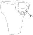
图6是通过本发明提供的单髁置换手术个性化智能导航定位装置的截骨示意图之一;Fig. 6 is one of the osteotomy schematic diagrams of the personalized intelligent navigation and positioning device for unicompartmental replacement surgery provided by the present invention;
图7是通过本发明提供的单髁置换手术个性化智能导航定位装置的截骨示意图之二;Fig. 7 is the second schematic diagram of the osteotomy of the personalized intelligent navigation and positioning device for unicompartmental replacement surgery provided by the present invention;
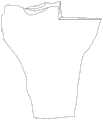
图8是利用本发明提供的截骨器进行单髁胫骨截骨手术后,胫骨的结构示意图;Fig. 8 is a schematic view of the structure of the tibia after performing unicondylar tibial osteotomy using the osteotomy provided by the present invention;
图9是对本发明提供的单髁置换手术个性化智能导航定位装置的安装及截骨流程示意图。Fig. 9 is a schematic diagram of the installation and osteotomy process of the personalized intelligent navigation and positioning device for unicompartmental replacement surgery provided by the present invention.
附图标记:Reference signs:
1、导板本体;2、截骨槽;3、通孔;4、第一拟合部;5、第二拟合部;6、第三拟合部;8、第一连接孔;9、第二连接孔;10、第一侧壁;11、第二侧壁;12、第三侧壁;13、螺纹钉;14、摆锯。1. Guide plate body; 2. Osteotomy groove; 3. Through hole; 4. First fitting part; 5. Second fitting part; 6. Third fitting part; 8. First connecting hole; 9. Second fitting part Two connecting holes; 10, the first side wall; 11, the second side wall; 12, the third side wall; 13, threaded nails; 14, the pendulum saw.
具体实施方式Detailed ways
下面结合附图和实施例对本发明的实施方式作进一步详细描述。以下实施例用于说明本发明,但不能用来限制本发明的范围。Embodiments of the present invention will be further described in detail below in conjunction with the accompanying drawings and examples. The following examples are used to illustrate the present invention, but should not be used to limit the scope of the present invention.
在本发明实施例的描述中,需要说明的是,术语“中心”、“纵向”、“横向”、“上”、“下”、“前”、“后”、“左”、“右”、“竖直”、“水平”、“顶”、“底”、“内”、“外”等指示的方位或位置关系为基于附图所示的方位或位置关系,仅是为了便于描述本发明实施例和简化描述,而不是指示或暗示所指的装置或元件必须具有特定的方位、以特定的方位构造和操作,因此不能理解为对本发明实施例的限制。此外,术语“第一”、“第二”、“第三”仅用于描述目的,而不能理解为指示或暗示相对重要性。In the description of the embodiments of the present invention, it should be noted that the terms "center", "longitudinal", "transverse", "upper", "lower", "front", "rear", "left", "right" , "vertical", "horizontal", "top", "bottom", "inner", "outer" and other indicated orientations or positional relationships are based on the orientations or positional relationships shown in the drawings, and are only for the convenience of describing this The embodiments and simplified descriptions of the invention do not indicate or imply that the devices or elements referred to must have a specific orientation, be constructed and operate in a specific orientation, and therefore should not be construed as limiting the embodiments of the present invention. In addition, the terms "first", "second", and "third" are used for descriptive purposes only, and should not be construed as indicating or implying relative importance.
在本发明实施例的描述中,需要说明的是,除非另有明确的规定和限定,术语“相连”、“连接”应做广义理解,例如,可以是固定连接,也可以是可拆卸连接,或一体连接;可以是机械连接,也可以是电连接;可以是直接相连,也可以通过中间媒介间接相连。对于本领域的普通技术人员而言,可以具体情况理解上述术语在本发明实施例中的具体含义。In the description of the embodiments of the present invention, it should be noted that unless otherwise specified and limited, the terms "connected" and "connected" should be understood in a broad sense, for example, it can be a fixed connection or a detachable connection, Or integrated connection; it can be mechanical connection or electrical connection; it can be direct connection or indirect connection through an intermediary. Those of ordinary skill in the art can understand the specific meanings of the above terms in the embodiments of the present invention in specific situations.
在本发明实施例中,除非另有明确的规定和限定,第一特征在第二特征“上”或“下”可以是第一和第二特征直接接触,或第一和第二特征通过中间媒介间接接触。而且,第一特征在第二特征“之上”、“上方”和“上面”可是第一特征在第二特征正上方或斜上方,或仅仅表示第一特征水平高度高于第二特征。第一特征在第二特征“之下”、“下方”和“下面”可以是第一特征在第二特征正下方或斜下方,或仅仅表示第一特征水平高度小于第二特征。In the embodiments of the present invention, unless otherwise specified and limited, the first feature may be in direct contact with the first feature or the first feature and the second feature may pass through the middle of the second feature. Media indirect contact. Moreover, "above", "above" and "above" the first feature on the second feature may mean that the first feature is directly above or obliquely above the second feature, or simply means that the first feature is higher in level than the second feature. "Below", "beneath" and "beneath" the first feature may mean that the first feature is directly below or obliquely below the second feature, or simply means that the first feature is less horizontally than the second feature.
在本说明书的描述中,参考术语“一个实施例”、“一些实施例”、“示例”、“具体示例”、或“一些示例”等的描述意指结合该实施例或示例描述的具体特征、结构、材料或者特点包含于本发明实施例的至少一个实施例或示例中。在本说明书中,对上述术语的示意性表述不必须针对的是相同的实施例或示例。而且,描述的具体特征、结构、材料或者特点可以在任一个或多个实施例或示例中以合适的方式结合。此外,在不相互矛盾的情况下,本领域的技术人员可以将本说明书中描述的不同实施例或示例以及不同实施例或示例的特征进行结合和组合。In the description of this specification, descriptions referring to the terms "one embodiment", "some embodiments", "example", "specific examples", or "some examples" mean that specific features described in connection with the embodiment or example , structure, material or feature is included in at least one embodiment or example of the embodiments of the present invention. In this specification, the schematic representations of the above terms are not necessarily directed to the same embodiment or example. Furthermore, the described specific features, structures, materials or characteristics may be combined in any suitable manner in any one or more embodiments or examples. In addition, those skilled in the art can combine and combine different embodiments or examples and features of different embodiments or examples described in this specification without conflicting with each other.
下面结合图1-图8描述本发明的单髁置换手术个性化智能导航定位装置,该单髁置换手术个性化智能导航定位装置包括导板本体1,在导板本体1上设有截骨槽2和截面呈长方形的通孔3,截骨槽2的深度方向与通孔3的高度方向相同,截骨槽2的长度方向与通孔3的深度方向相同,截骨槽2的槽底高于通孔3的顶部,截骨槽2的截骨开口方向朝向导板本体1的顶部。其中,截骨槽2的截骨开口在屈曲位时指向髂前上嵴。The personalized intelligent navigation and positioning device for unicondylar replacement surgery of the present invention is described below in conjunction with Fig. 1-Fig. For a through
在本实施例中,通过截骨槽2和通孔3来辅助进行精准的截骨,其中,由于截骨槽2在屈曲位时(膝盖弯曲时)指向髂前上嵴,能够使截骨更加精准,在截骨完成后,使假体能够精准的放置,避免截骨后假体放歪或悬空,若假体放歪或悬空则会在伸直和屈曲过程中导致假体磨损严重,会引起内侧软组织刺激疼痛,造成术后感染,还会增加假体边缘载荷导致半月板衬垫的过度磨损,还会导致骨支撑不足,使其受力不均而易发生无菌性松动,造成假体脱位和下沉,因此,通过本方案可以避免术中医生根据自身经验进行截骨而造成术后疼痛、假体脱位、松动、下沉、旋转对位不良和术后感染等并发症,提高了手术的成功率和假体的生存率。In this embodiment, the precise osteotomy is assisted by the
其中,截骨槽2为矢状位截骨槽,在进行单髁胫骨截骨手术时,截骨槽2位于内侧髁间嵴的内侧斜坡上,此时截骨槽2可以起到很好的参考标志作用,且由于截骨槽2的上侧在导板本体1的顶部形成截骨缺口,可以十分便于利用摆锯14进行切割。Among them, the
膝关节在屈曲和伸直过程中,势必会伴随有胫骨相对于股骨的内外旋,倘若截骨精度不够,假体安装位置有放歪或悬空的可能,在屈曲和伸直过程中会引起内侧软组织刺激疼痛,甚至术后感染,同时,胫骨假体的悬空不仅会增加垫片边缘载荷导致半月板衬垫的过度磨损,还会导致骨支撑不足,使其受力不均而易发生无菌性松动,造成假体脱位和下沉。通过本方案中的截骨导板进行辅助截骨,可以精确的把握截骨方向,在截骨完成并进行假体放置后,可以使假体能更好的满足膝关节在屈曲和伸直过程中生理上的内外旋。In the process of flexion and extension of the knee joint, there will inevitably be internal and external rotation of the tibia relative to the femur. If the osteotomy is not accurate enough, the prosthesis installation position may be skewed or suspended, which will cause medial inflexion and extension. Soft tissue irritation and pain, and even postoperative infection. At the same time, the suspension of the tibial prosthesis will not only increase the edge load of the spacer and cause excessive wear of the meniscus liner, but also lead to insufficient bone support, causing uneven force and prone to aseptic Sexual loosening, resulting in dislocation and subsidence of the prosthesis. The osteotomy guide plate in this program can be used to assist osteotomy, and the direction of osteotomy can be accurately grasped. After the osteotomy is completed and the prosthesis is placed, the prosthesis can better meet the needs of the knee joint in the process of flexion and extension. Physiological internal and external rotation.
通孔3的结构可以使通孔3的两端均为封闭设计,如图1所示,通孔3的左侧位于靠近截骨槽2下侧的位置,通孔3的右侧为封闭设置,如图1可知,通孔3的左侧也为封闭设置。将通孔3的右侧设置为封闭状态,可以避免在手术过程中由于保护不到位而伤及内侧副韧带。The structure of the through
根据本发明提供的单髁置换手术个性化智能导航定位装置,通孔3的第一侧壁10在通孔3高度方向的投影位于截骨槽2的第二侧壁11和第三侧壁12在截骨槽2深度方向的投影区域之间。具体的通孔3的第一侧壁10可以与截骨槽2的第二侧壁11的投影重合。利用这样的方式可以使摆锯14通过截骨槽2和通孔3进行切割后,其中一侧的切割位置相适配,更好的保证精确的截骨。According to the personalized intelligent navigation and positioning device for unicondylar replacement surgery provided by the present invention, the projection of the
其中,导板本体1用于与胫骨相连的一侧为拟合连接侧,拟合连接侧在第一高度位置处设置有第一拟合部4和第二拟合部5,拟合连接侧在第二高度位置处设置有第三拟合部6,在第一拟合部4和第二拟合部5之间形成截骨槽2。如图1和图2所示,第一拟合部4、第二拟合部5和第三拟合部6的连接面的形状与胫骨相对应的位置的形状相同,第一拟合部4、第二拟合部5和第三拟合部6用于与相对应的胫骨区域精准拟合,实现导板本体1与胫骨之间精准连接。Wherein, the side of the
可以理解的是,截骨槽2包括有两部分,一部分位于导板本体1上,另一部分由第一拟合部4和第二拟合部5之间的间隙形成,两部分相连通形成截骨槽2。It can be understood that the
沿导板本体1的竖直方向(也即截骨槽的深度方向),第一高度位置高于第二高度位置,在本发明实施例中,第一高度位置为导板本体1竖直方向的顶部,第二高度位置为导板本体1的竖直方向中部。Along the vertical direction of the guide plate body 1 (that is, the depth direction of the osteotomy groove), the first height position is higher than the second height position. In the embodiment of the present invention, the first height position is the top of the
第一拟合部4和第二拟合部5设置于导板本体1的拟合连接侧的顶部位置,以使第一拟合部4和第二拟合部5能拟合挂接在胫骨的上侧区域,第三拟合部6大致设置于导板本体1的拟合连接侧的中部区域,在进行单髁胫骨截骨手术时,第三拟合部6位于胫骨前方内侧,且第三拟合部6避让了髌韧带,在术中更方便拟合。The first
其中,第一拟合部4、第二拟合部5和第三拟合部6的拟合区域(也即与胫骨的连接区域)为凹凸不平的形状,可以增强导板的拟合稳定性。Wherein, the fitting areas of the first
根据本发明提供的单髁置换手术个性化智能导航定位装置,第一拟合部4的长度大于第二拟合部5的长度,第一拟合部4用于延伸至前交叉韧带内侧,如图4所示,第一拟合部4位于导板本体1靠左侧的位置,第一拟合部4的能延伸至前交叉韧带内侧,从而保护前交叉韧带,以防止在矢状位截骨时伤及前交叉韧带。According to the personalized intelligent navigation and positioning device for unicompartmental replacement surgery provided by the present invention, the length of the first
如图4所示,第一拟合部4的宽度远小于第二拟合部5的宽度。As shown in FIG. 4 , the width of the first
其中,第一拟合部4、第二拟合部5和第三拟合部6均朝垂直于导板本体1的方向延伸,以使第一拟合部4、第二拟合部5和第三拟合部6能很好的与胫骨实现拟合相连。Wherein, the first
根据本发明提供的单髁置换手术个性化智能导航定位装置,在导板本体1上开设有第一连接孔8和第二连接孔9,其中,第一连接孔8和第二连接孔9均适于通过紧固件与胫骨相连。可以理解的是,导板本体1一方面通过第一拟合部4、第二拟合部5和第三拟合部6与胫骨拟合相连后实现精准的定位和连接,另一方面通过紧固件配合第一连接孔8和第二连接孔9,来使导板本体1的固定更加牢靠。According to the personalized intelligent navigation and positioning device for unicompartmental replacement surgery provided by the present invention, a
其中,第一连接孔8在导板本体1上垂直设置,第二连接孔9在导板本体1上倾斜设置。此时,紧固件从第一连接孔8垂直打入胫骨,紧固件从第二连接孔9斜向打入胫骨,以使第一连接孔8和第二连接孔9在空间上互不干涉,这样可以加强导板本体1的固定性,有效避免单髁胫骨截骨过程中导板本体1松动而导致截骨倾斜的可能。Wherein, the
在本发明的另一个实施例中,第一连接孔8在导板本体1上倾斜设置,第二连接孔9在导板本体1上垂直设置,此时,紧固件从第一连接孔8斜向打入胫骨,紧固件从第二连接孔9垂直打入胫骨,以使第一连接孔8和第二连接孔9在空间上互不干涉,这样可以加强导板本体1的固定性,有效避免单髁胫骨截骨过程中导板本体1松动而导致截骨倾斜的可能。In another embodiment of the present invention, the
其中,沿导板本体1的竖直方向,第一连接孔8和第二连接孔9均位于通孔3的下侧,其中,导板本体1的竖直方向与截骨槽2的深度方向相同,在进行单髁胫骨截骨时,摆锯14会从通孔3中穿过以对胫骨进行截骨,由于通孔3的上方区域利用了第一拟合部4和第二拟合部5来实现导板本体1的连接,且通孔3的下方区域利用了第一连接孔8、第二连接孔9配合紧固件来实现导板本体1的连接,这样便可使通孔3的位置十分稳定,不会出现术中截骨位置出现偏移的情况。Wherein, along the vertical direction of the
第一连接孔8的孔中心和第二连接孔9的孔中心位于不同的高度位置,可以理解的是,在利用紧固件进行导板本体1位置的进一步固定时,两个紧固件可以在导板本体1的不同高度位置进行辅助固定,从而使导板本体1能固定的更加牢靠。The hole center of the first connecting
根据本发明提供的单髁置换手术个性化智能导航定位装置,单髁置换手术个性化智能导航定位装置为采用3D打印技术一体成型的单髁置换手术个性化智能导航定位装置,也即,根据不同患者的胫骨状态,采用3D打印技术制造不同的单髁置换手术个性化智能导航定位装置,以使第一拟合部4、第二拟合部5和第三拟合部6能精准的与不同患者的胫骨进行拟合连接,实现单髁置换手术个性化智能导航定位装置的个性化设计。According to the personalized intelligent navigation and positioning device for unicondylar replacement surgery provided by the present invention, the personalized intelligent navigation and positioning device for unicondylar replacement surgery is an integrated intelligent navigation and positioning device for unicondylar replacement surgery using 3D printing technology, that is, according to different The state of the patient's tibia, using 3D printing technology to manufacture different personalized intelligent navigation and positioning devices for unicompartmental replacement surgery, so that the first
本发明提供的单髁置换手术个性化智能导航定位装置,具有三个拟合区域,能更加精准的放置并贴附导板本体1,实现精准的截骨,避免由于截骨不准而造成多次截骨,减少了手术时间,降低了手术风险,有利于患者术后恢复,降低了翻修概率,同时提高了手术的成功率和假体的生存率。The personalized intelligent navigation and positioning device for unicondylar replacement surgery provided by the present invention has three fitting areas, which can be more accurately placed and attached to the
接下来,参见图9,对单髁置换手术个性化智能导航定位装置的安装及截骨过程进行描述。具体的,包括以下步骤:Next, referring to FIG. 9 , the installation and osteotomy process of the personalized intelligent navigation and positioning device for unicompartmental replacement surgery will be described. Specifically, the following steps are included:
步骤90:开始Step 90: Start
步骤91:去除胫骨平台与单髁置换手术个性化智能导航定位装置进行拟合时的拟合面上的软骨。Step 91: removing the cartilage on the fitting surface of the tibial plateau and the personalized intelligent navigation and positioning device for unicompartmental replacement surgery.
步骤92:将单髁置换手术个性化智能导航定位装置与胫骨平台的拟合面进行拟合(如图3所示),即,导航定位装置拟合胫骨前内侧。Step 92: Fit the personalized intelligent navigation and positioning device for unicompartmental replacement surgery with the fitting surface of the tibial plateau (as shown in FIG. 3 ), that is, the navigation and positioning device fits the anteromedial side of the tibia.
步骤93:将两个螺纹钉13分别植入第一连接孔8和第二连接孔9中(如图5所示),实现导航定位装置与胫骨之间的固定,其中螺纹钉13可以为上文提到的紧固件。Step 93: Insert two threaded
步骤94:利用摆锯14沿着通孔3的方向进行截骨操作(如图6所示),即进行冠状位截骨。在沿通孔3的方向将胫骨截穿后,停止截骨。Step 94: Use the oscillating saw 14 to perform an osteotomy along the direction of the through hole 3 (as shown in FIG. 6 ), that is, perform a coronal osteotomy. After the tibia is cut through in the direction of the through
步骤95:利用摆锯14沿着截骨槽2的深度方向进行截骨操作(如图7所示),即进行矢状位截骨。在摆锯14沿截骨槽2的深度方向截骨至截骨槽2的最低处时,停止截骨。Step 95: Use the oscillating saw 14 to perform an osteotomy along the depth direction of the osteotomy groove 2 (as shown in FIG. 7 ), that is, perform a sagittal osteotomy. When the pendulum saw 14 cuts the osteotomy to the lowest point of the
步骤96:将两个螺纹钉13分别从第一连接孔8和第二连接孔9中拆除,取下单髁置换手术个性化智能导航定位装置及被截骨部分(如图8所示),完成截骨操作。Step 96: Remove the two threaded
步骤97:结束。Step 97: end.
接下来,对单髁置换手术个性化智能导航定位装置的规划方法进行示例性说明。Next, the planning method of the personalized intelligent navigation and positioning device for unicompartmental replacement surgery is exemplified.
首先,根据患者骨模型确定胫骨机械轴(膝关节中心至踝关节中心连线),进而确定横断面,其中,横断面垂直于机械轴;First, determine the mechanical axis of the tibia (the line connecting the center of the knee joint to the center of the ankle joint) according to the patient's bone model, and then determine the cross-section, where the cross-section is perpendicular to the mechanical axis;
然后,根据后交叉韧带中点到胫骨结节内侧缘连线确定Akagi线,确定矢状面;Then, the Akagi line was determined according to the line connecting the midpoint of the posterior cruciate ligament to the medial edge of the tibial tuberosity, and the sagittal plane was determined;
其次,在失状位上测量患者胫骨内侧后倾角,其中,胫骨内侧后倾角一般为0-7°;Secondly, measure the medial tibial retroversion angle of the patient in the lost position, where the medial tibial retroversion angle is generally 0-7°;
再次,确定通孔的位置,即沿通孔进行横向截骨的方向与患者胫骨后倾角保持一致,截骨厚度距离平台内侧最低点2-5mm;Thirdly, determine the position of the through hole, that is, the direction of transverse osteotomy along the through hole is consistent with the patient’s tibial retroversion angle, and the thickness of the osteotomy is 2-5mm from the innermost point of the platform;
最后,确定截骨槽的位置,即沿截骨槽进行失状位截骨的方向在膝关节处于屈曲位时指向髂前上嵴,截骨位置位于距内侧髁间嵴1-2mm;根据通孔和截骨槽的位置,设计生成完整的单髁置换手术个性化智能导航定位装置的模型,通过该模型进行3D打印,制成本发明的单髁置换手术个性化智能导航定位装置。Finally, determine the position of the osteotomy slot, that is, the direction of osteotomy at the loss of shape along the osteotomy slot points to the anterior superior iliac crest when the knee joint is in flexion, and the osteotomy position is located 1-2 mm from the medial intercondylar crest; The position of the hole and the osteotomy slot is designed to generate a complete model of the personalized intelligent navigation and positioning device for unicondylar replacement surgery, and the model is 3D printed to make the personalized intelligent navigation and positioning device for unicondylar replacement surgery of the present invention.
另一方面,本发明提供了一种单髁置换手术个性化智能导航定位装置的使用方法,包括:In another aspect, the present invention provides a method for using a personalized intelligent navigation and positioning device for unicompartmental replacement surgery, including:
将所述单髁置换手术个性化智能导航定位装置与胫骨平台的拟合面进行拟合;Fitting the personalized intelligent navigation and positioning device for the unicompartmental replacement surgery with the fitting surface of the tibial plateau;
拟合完成后,通过紧固件对所述单髁置换手术个性化智能导航定位装置进行固定;After the fitting is completed, the personalized intelligent navigation and positioning device for the unicompartmental replacement surgery is fixed by fasteners;
利用摆锯14,分别通过所述通孔及所述截骨槽进行矢状位及冠状位的截骨操作;Utilize pendulum saw 14, carry out the osteotomy operation of sagittal position and coronal position through described through hole and described osteotomy groove respectively;
取下所述紧固件及所述单髁置换手术个性化智能导航定位装置,完成截骨操作。The fastener and the personalized intelligent navigation and positioning device for unicompartmental replacement surgery are removed to complete the osteotomy operation.
另一方面,本发明还提供一种截骨器,该截骨器包括摆锯14和前述实施例中的单髁置换手术个性化智能导航定位装置,其中,摆锯14适于穿设于截骨槽2和/或通孔3内,在进行单髁胫骨截骨手术时,如图3和图4所示,先利用第一拟合部4、第二拟合部5和第三拟合部6将导板本体1准确的固定于胫骨上,再通过紧固件配合第一连接孔8和第二连接孔9来使导板本体1的位置稳固,然后使用摆锯14先后沿截骨槽2和通孔3进行截骨,从而完成胫骨侧的截骨手术,进而使胫骨截骨后形成如图5所示的形状。On the other hand, the present invention also provides an osteotomy device, which includes an oscillating saw 14 and the personalized intelligent navigation and positioning device for unicondylar replacement surgery in the aforementioned embodiments, wherein the oscillating saw 14 is suitable for passing through the In the
最后应说明的是:以上实施例仅用以说明本发明的技术方案,而非对其限制;尽管参照前述实施例对本发明进行了详细的说明,本领域的普通技术人员应当理解:其依然可以对前述各实施例所记载的技术方案进行修改,或者对其中部分技术特征进行等同替换;而这些修改或者替换,并不使相应技术方案的本质脱离本发明各实施例技术方案的精神和范围。Finally, it should be noted that: the above embodiments are only used to illustrate the technical solutions of the present invention, rather than to limit them; although the present invention has been described in detail with reference to the foregoing embodiments, those of ordinary skill in the art should understand that: it can still be Modifications are made to the technical solutions described in the foregoing embodiments, or equivalent replacements are made to some of the technical features; and these modifications or replacements do not make the essence of the corresponding technical solutions deviate from the spirit and scope of the technical solutions of the various embodiments of the present invention.
Claims (7)
Translated fromChinesePriority Applications (2)
| Application Number | Priority Date | Filing Date | Title |
|---|---|---|---|
| CN202210616223.5ACN115005986B (en) | 2022-05-31 | 2022-05-31 | Individual intelligent navigation positioning device for single condyle replacement surgery and osteotome |
| PCT/CN2023/082702WO2023231522A1 (en) | 2022-05-31 | 2023-03-21 | Personalized intelligent navigation and positioning apparatus and method for unicompartmental knee arthroplasty |
Applications Claiming Priority (1)
| Application Number | Priority Date | Filing Date | Title |
|---|---|---|---|
| CN202210616223.5ACN115005986B (en) | 2022-05-31 | 2022-05-31 | Individual intelligent navigation positioning device for single condyle replacement surgery and osteotome |
Publications (2)
| Publication Number | Publication Date |
|---|---|
| CN115005986A CN115005986A (en) | 2022-09-06 |
| CN115005986Btrue CN115005986B (en) | 2023-04-07 |
Family
ID=83070943
Family Applications (1)
| Application Number | Title | Priority Date | Filing Date |
|---|---|---|---|
| CN202210616223.5AActiveCN115005986B (en) | 2022-05-31 | 2022-05-31 | Individual intelligent navigation positioning device for single condyle replacement surgery and osteotome |
Country Status (2)
| Country | Link |
|---|---|
| CN (1) | CN115005986B (en) |
| WO (1) | WO2023231522A1 (en) |
Families Citing this family (1)
| Publication number | Priority date | Publication date | Assignee | Title |
|---|---|---|---|---|
| CN115005986B (en)* | 2022-05-31 | 2023-04-07 | 北京长木谷医疗科技有限公司 | Individual intelligent navigation positioning device for single condyle replacement surgery and osteotome |
Citations (5)
| Publication number | Priority date | Publication date | Assignee | Title |
|---|---|---|---|---|
| FR2854061A1 (en)* | 2003-04-24 | 2004-10-29 | Aesculap Sa | Posterior-stabilized knee prosthesis, has curve, delimiting transversal cut section of femoral mount, and defined so that central point of contact zone undergoes translation towards back, which decreases as function of bending angle |
| CN105193475A (en)* | 2015-08-18 | 2015-12-30 | 长沙市第三医院 | Individualized bone cutting guide plate suite and design method thereof |
| CN210472337U (en)* | 2019-04-04 | 2020-05-08 | 经纬医疗器材制造(深圳)有限公司 | Knee joint femoral prosthesis test mould with intercondylar osteotomy slot |
| CN111467089A (en)* | 2020-05-07 | 2020-07-31 | 苏州微创关节医疗科技有限公司 | Interchangeable Unicondylar Femoral Prosthesis System and Knee Joint System |
| CN113397651A (en)* | 2021-07-21 | 2021-09-17 | 袁海浪 | Method for positioning longitudinal tibial osteotomy position in unicondylar replacement |
Family Cites Families (11)
| Publication number | Priority date | Publication date | Assignee | Title |
|---|---|---|---|---|
| CN107320153B (en)* | 2017-08-17 | 2023-11-07 | 苏州中科生物医用材料有限公司 | Tibia medial high-level osteotomy auxiliary tool |
| WO2019137626A1 (en)* | 2018-01-15 | 2019-07-18 | Episurf Ip-Management Ab | Tools for assisting in osteotomy procedures, and methods for designing and manufacturing osteotomy tools |
| CN108309394A (en)* | 2018-03-12 | 2018-07-24 | 北京市春立正达医疗器械股份有限公司 | A kind of osteotomy positioning device again for shin bone |
| JP7189758B2 (en)* | 2018-12-25 | 2022-12-14 | 京セラ株式会社 | Surgical instruments and surgical instrument systems |
| CN210932054U (en)* | 2019-07-05 | 2020-07-07 | 扬州大学附属医院 | Auxiliary bone cutting guide plate for knee joint unicondylar replacement |
| CN110353759B (en)* | 2019-07-22 | 2024-09-13 | 北京长木谷医疗科技股份有限公司 | Osteotomy guide plate |
| CN110393572B (en)* | 2019-07-30 | 2022-05-10 | 西安市红会医院 | Preparation method of personalized 3D printed tibial high osteotomy guide plate |
| CN110960289B (en)* | 2019-12-03 | 2021-07-27 | 嘉思特华剑医疗器材(天津)有限公司 | Single-condyle bone cutting guide plate and positioning method thereof |
| CN113317843B (en)* | 2021-05-08 | 2022-08-26 | 广东医科大学附属医院 | Preparation method of precise tibia cutting guide plate for individualized knee joint unicondylar replacement |
| CN113995466B (en)* | 2021-10-28 | 2023-05-12 | 北京长木谷医疗科技有限公司 | Tibia osteotomy device and tibia osteotomy guide plate assembly |
| CN115005986B (en)* | 2022-05-31 | 2023-04-07 | 北京长木谷医疗科技有限公司 | Individual intelligent navigation positioning device for single condyle replacement surgery and osteotome |
- 2022
- 2022-05-31CNCN202210616223.5Apatent/CN115005986B/enactiveActive
- 2023
- 2023-03-21WOPCT/CN2023/082702patent/WO2023231522A1/ennot_activeCeased
Patent Citations (5)
| Publication number | Priority date | Publication date | Assignee | Title |
|---|---|---|---|---|
| FR2854061A1 (en)* | 2003-04-24 | 2004-10-29 | Aesculap Sa | Posterior-stabilized knee prosthesis, has curve, delimiting transversal cut section of femoral mount, and defined so that central point of contact zone undergoes translation towards back, which decreases as function of bending angle |
| CN105193475A (en)* | 2015-08-18 | 2015-12-30 | 长沙市第三医院 | Individualized bone cutting guide plate suite and design method thereof |
| CN210472337U (en)* | 2019-04-04 | 2020-05-08 | 经纬医疗器材制造(深圳)有限公司 | Knee joint femoral prosthesis test mould with intercondylar osteotomy slot |
| CN111467089A (en)* | 2020-05-07 | 2020-07-31 | 苏州微创关节医疗科技有限公司 | Interchangeable Unicondylar Femoral Prosthesis System and Knee Joint System |
| CN113397651A (en)* | 2021-07-21 | 2021-09-17 | 袁海浪 | Method for positioning longitudinal tibial osteotomy position in unicondylar replacement |
Also Published As
| Publication number | Publication date |
|---|---|
| WO2023231522A1 (en) | 2023-12-07 |
| CN115005986A (en) | 2022-09-06 |
Similar Documents
| Publication | Publication Date | Title |
|---|---|---|
| US12274452B2 (en) | Surgical kit for tibial resection and replacement | |
| US6059831A (en) | Method of implanting a uni-condylar knee prosthesis | |
| EP0773756B1 (en) | Asymmetric femoral prosthesis | |
| Insall et al. | Total condylar knee replacement: preliminary report | |
| US8377141B2 (en) | Knee prosthesis | |
| JP5208116B2 (en) | Posterior stable knee prosthesis | |
| US5702460A (en) | Revision femoral trial prosthesis | |
| KR101686853B1 (en) | Patient specific surgical guide locator and mount | |
| US20090198340A1 (en) | Femoral component of knee prosthesis, the femoral component having anterior/posterior claw(s) for digging into bone and/or a raised rib with a bulbous terminus | |
| CN110638508B (en) | Customized, patient-specific plastic surgery devices | |
| US20140364857A1 (en) | Joint Arthroplasty Devices, Systems, and Methods | |
| US9993256B2 (en) | Customized unicompartmental tibial cutting guide | |
| EP2434991A2 (en) | Methods and apparatus for performing knee arthroplasty | |
| US12324591B2 (en) | Osteotomy guide | |
| CN115005986B (en) | Individual intelligent navigation positioning device for single condyle replacement surgery and osteotome | |
| Insall et al. | Total condylar knee replacement: preliminary report | |
| CN217592978U (en) | 3D prints assembled knee joint and cuts bone baffle | |
| JPH11113940A (en) | Resect-assisting utensil for knee joint | |
| US20220354508A1 (en) | Cutting block | |
| KR102359302B1 (en) | Patient-specific pin guide for total knee arthroplasty including an anatomical theory-based lower extremity alignment check part | |
| CN216754441U (en) | Gap detector combining straightening gap and buckling gap | |
| CN222983108U (en) | Osteotomy device | |
| CN221786470U (en) | Femoral distal end cuts bone unicondylar replacement baffle | |
| CN216754620U (en) | An adjustable gap detector | |
| CN205697923U (en) | Osteotomy adjusting means between a kind of condyle |
Legal Events
| Date | Code | Title | Description |
|---|---|---|---|
| PB01 | Publication | ||
| PB01 | Publication | ||
| SE01 | Entry into force of request for substantive examination | ||
| SE01 | Entry into force of request for substantive examination | ||
| GR01 | Patent grant | ||
| GR01 | Patent grant | ||
| CP01 | Change in the name or title of a patent holder | Address after:100176 2201, 22 / F, building 1, yard 2, Ronghua South Road, Beijing Economic and Technological Development Zone, Daxing District, Beijing Patentee after:Beijing Changmugu Medical Technology Co.,Ltd. Patentee after:Zhang Yiling Address before:100176 2201, 22 / F, building 1, yard 2, Ronghua South Road, Beijing Economic and Technological Development Zone, Daxing District, Beijing Patentee before:BEIJING CHANGMUGU MEDICAL TECHNOLOGY Co.,Ltd. Patentee before:Zhang Yiling | |
| CP01 | Change in the name or title of a patent holder |