CN115003262A - Syringes and tightness test methods - Google Patents
Syringes and tightness test methodsDownload PDFInfo
- Publication number
- CN115003262A CN115003262ACN202080092093.9ACN202080092093ACN115003262ACN 115003262 ACN115003262 ACN 115003262ACN 202080092093 ACN202080092093 ACN 202080092093ACN 115003262 ACN115003262 ACN 115003262A
- Authority
- CN
- China
- Prior art keywords
- stopper
- plunger
- cavity
- syringe
- barrel
- Prior art date
- Legal status (The legal status is an assumption and is not a legal conclusion. Google has not performed a legal analysis and makes no representation as to the accuracy of the status listed.)
- Pending
Links
Images


Classifications
- A—HUMAN NECESSITIES
- A61—MEDICAL OR VETERINARY SCIENCE; HYGIENE
- A61P—SPECIFIC THERAPEUTIC ACTIVITY OF CHEMICAL COMPOUNDS OR MEDICINAL PREPARATIONS
- A61P27/00—Drugs for disorders of the senses
- A61P27/02—Ophthalmic agents
- A—HUMAN NECESSITIES
- A61—MEDICAL OR VETERINARY SCIENCE; HYGIENE
- A61M—DEVICES FOR INTRODUCING MEDIA INTO, OR ONTO, THE BODY; DEVICES FOR TRANSDUCING BODY MEDIA OR FOR TAKING MEDIA FROM THE BODY; DEVICES FOR PRODUCING OR ENDING SLEEP OR STUPOR
- A61M5/00—Devices for bringing media into the body in a subcutaneous, intra-vascular or intramuscular way; Accessories therefor, e.g. filling or cleaning devices, arm-rests
- A61M5/178—Syringes
- A61M5/31—Details
- A61M5/315—Pistons; Piston-rods; Guiding, blocking or restricting the movement of the rod or piston; Appliances on the rod for facilitating dosing ; Dosing mechanisms
- A61M5/31511—Piston or piston-rod constructions, e.g. connection of piston with piston-rod
- A61M5/31513—Piston constructions to improve sealing or sliding
- A—HUMAN NECESSITIES
- A61—MEDICAL OR VETERINARY SCIENCE; HYGIENE
- A61F—FILTERS IMPLANTABLE INTO BLOOD VESSELS; PROSTHESES; DEVICES PROVIDING PATENCY TO, OR PREVENTING COLLAPSING OF, TUBULAR STRUCTURES OF THE BODY, e.g. STENTS; ORTHOPAEDIC, NURSING OR CONTRACEPTIVE DEVICES; FOMENTATION; TREATMENT OR PROTECTION OF EYES OR EARS; BANDAGES, DRESSINGS OR ABSORBENT PADS; FIRST-AID KITS
- A61F9/00—Methods or devices for treatment of the eyes; Devices for putting in contact-lenses; Devices to correct squinting; Apparatus to guide the blind; Protective devices for the eyes, carried on the body or in the hand
- A61F9/0008—Introducing ophthalmic products into the ocular cavity or retaining products therein
- A61F9/0017—Introducing ophthalmic products into the ocular cavity or retaining products therein implantable in, or in contact with, the eye, e.g. ocular inserts
- A—HUMAN NECESSITIES
- A61—MEDICAL OR VETERINARY SCIENCE; HYGIENE
- A61M—DEVICES FOR INTRODUCING MEDIA INTO, OR ONTO, THE BODY; DEVICES FOR TRANSDUCING BODY MEDIA OR FOR TAKING MEDIA FROM THE BODY; DEVICES FOR PRODUCING OR ENDING SLEEP OR STUPOR
- A61M5/00—Devices for bringing media into the body in a subcutaneous, intra-vascular or intramuscular way; Accessories therefor, e.g. filling or cleaning devices, arm-rests
- A61M5/178—Syringes
- A61M5/31—Details
- A61M5/3129—Syringe barrels
- G—PHYSICS
- G01—MEASURING; TESTING
- G01M—TESTING STATIC OR DYNAMIC BALANCE OF MACHINES OR STRUCTURES; TESTING OF STRUCTURES OR APPARATUS, NOT OTHERWISE PROVIDED FOR
- G01M3/00—Investigating fluid-tightness of structures
- G01M3/02—Investigating fluid-tightness of structures by using fluid or vacuum
- G01M3/04—Investigating fluid-tightness of structures by using fluid or vacuum by detecting the presence of fluid at the leakage point
- G—PHYSICS
- G01—MEASURING; TESTING
- G01M—TESTING STATIC OR DYNAMIC BALANCE OF MACHINES OR STRUCTURES; TESTING OF STRUCTURES OR APPARATUS, NOT OTHERWISE PROVIDED FOR
- G01M3/00—Investigating fluid-tightness of structures
- G01M3/02—Investigating fluid-tightness of structures by using fluid or vacuum
- G01M3/26—Investigating fluid-tightness of structures by using fluid or vacuum by measuring rate of loss or gain of fluid, e.g. by pressure-responsive devices, by flow detectors
- A—HUMAN NECESSITIES
- A61—MEDICAL OR VETERINARY SCIENCE; HYGIENE
- A61M—DEVICES FOR INTRODUCING MEDIA INTO, OR ONTO, THE BODY; DEVICES FOR TRANSDUCING BODY MEDIA OR FOR TAKING MEDIA FROM THE BODY; DEVICES FOR PRODUCING OR ENDING SLEEP OR STUPOR
- A61M2205/00—General characteristics of the apparatus
- A61M2205/02—General characteristics of the apparatus characterised by a particular materials
- A61M2205/0238—General characteristics of the apparatus characterised by a particular materials the material being a coating or protective layer
- A—HUMAN NECESSITIES
- A61—MEDICAL OR VETERINARY SCIENCE; HYGIENE
- A61M—DEVICES FOR INTRODUCING MEDIA INTO, OR ONTO, THE BODY; DEVICES FOR TRANSDUCING BODY MEDIA OR FOR TAKING MEDIA FROM THE BODY; DEVICES FOR PRODUCING OR ENDING SLEEP OR STUPOR
- A61M2209/00—Ancillary equipment
- A61M2209/02—Equipment for testing the apparatus
- A—HUMAN NECESSITIES
- A61—MEDICAL OR VETERINARY SCIENCE; HYGIENE
- A61M—DEVICES FOR INTRODUCING MEDIA INTO, OR ONTO, THE BODY; DEVICES FOR TRANSDUCING BODY MEDIA OR FOR TAKING MEDIA FROM THE BODY; DEVICES FOR PRODUCING OR ENDING SLEEP OR STUPOR
- A61M5/00—Devices for bringing media into the body in a subcutaneous, intra-vascular or intramuscular way; Accessories therefor, e.g. filling or cleaning devices, arm-rests
- A61M5/001—Apparatus specially adapted for cleaning or sterilising syringes or needles
- A—HUMAN NECESSITIES
- A61—MEDICAL OR VETERINARY SCIENCE; HYGIENE
- A61M—DEVICES FOR INTRODUCING MEDIA INTO, OR ONTO, THE BODY; DEVICES FOR TRANSDUCING BODY MEDIA OR FOR TAKING MEDIA FROM THE BODY; DEVICES FOR PRODUCING OR ENDING SLEEP OR STUPOR
- A61M5/00—Devices for bringing media into the body in a subcutaneous, intra-vascular or intramuscular way; Accessories therefor, e.g. filling or cleaning devices, arm-rests
- A61M5/178—Syringes
- A61M5/31—Details
- A61M5/315—Pistons; Piston-rods; Guiding, blocking or restricting the movement of the rod or piston; Appliances on the rod for facilitating dosing ; Dosing mechanisms
- A61M5/31511—Piston or piston-rod constructions, e.g. connection of piston with piston-rod
- A61M5/31515—Connection of piston with piston rod
Landscapes
- Health & Medical Sciences (AREA)
- Engineering & Computer Science (AREA)
- Life Sciences & Earth Sciences (AREA)
- Animal Behavior & Ethology (AREA)
- General Health & Medical Sciences (AREA)
- Public Health (AREA)
- Veterinary Medicine (AREA)
- Vascular Medicine (AREA)
- Biomedical Technology (AREA)
- Heart & Thoracic Surgery (AREA)
- Anesthesiology (AREA)
- Hematology (AREA)
- Physics & Mathematics (AREA)
- General Physics & Mathematics (AREA)
- Ophthalmology & Optometry (AREA)
- Bioinformatics & Cheminformatics (AREA)
- Chemical & Material Sciences (AREA)
- Chemical Kinetics & Catalysis (AREA)
- General Chemical & Material Sciences (AREA)
- Medicinal Chemistry (AREA)
- Nuclear Medicine, Radiotherapy & Molecular Imaging (AREA)
- Organic Chemistry (AREA)
- Pharmacology & Pharmacy (AREA)
- Infusion, Injection, And Reservoir Apparatuses (AREA)
- Measuring Or Testing Involving Enzymes Or Micro-Organisms (AREA)
- Apparatus Associated With Microorganisms And Enzymes (AREA)
Abstract
Description
Translated fromChinese技术领域technical field
本发明涉及一种注射器,更具体地,涉及一种测试注射器的止挡件和柱塞之间的密封性/紧密度的方法。The present invention relates to a syringe, and more particularly, to a method of testing the tightness/tightness between a stopper and a plunger of a syringe.
这样的注射器包括(i)筒体,其具有中空内部、孔口和与孔口相对的开口,(ii)止挡件,其布置在筒体的中空内部中,从而在筒体内部限定密封腔室,其中,止挡件可以在筒体的内部移动,从而改变腔室的容积,和(iii)柱塞,其通过筒体的开口延伸到筒体的中空内部中,可用于将药物物质输送到患者。特别地,在注射器被实施为预填充式注射器的情况下,它可以允许方便地将预定剂量的药物物质施用于患者。Such a syringe includes (i) a barrel having a hollow interior, an orifice and an opening opposite the orifice, (ii) a stopper disposed in the hollow interior of the barrel to define a sealed cavity inside the barrel a chamber, wherein the stopper can move within the interior of the barrel, thereby changing the volume of the chamber, and (iii) a plunger, which extends through the opening of the barrel into the hollow interior of the barrel, which can be used to deliver the drug substance to the patient. In particular, where the syringe is embodied as a prefilled syringe, it may allow convenient administration of a predetermined dose of the drug substance to the patient.
背景技术Background technique
许多药物或药物物质以液体形式给药。为了有效的给药和功效,液体药物物质通常通过注射进行肠胃外输送。因此,特别是对于皮下、肌内、皮内或玻璃体内注射,通常在预填充式注射器(PFS)中提供药物物质。这样的PFS可以具有桩针或能够接纳单独的连接针。在PFS中,药物物质以溶液、悬浮液或其它准备好给药的液体形式被提供在注射器筒体的内部。PFS的优点可以在于使用者接收到(准)准备好注射的注射器,而无需诸如例如通过从小瓶等转移来为注射器填充药物物质的准备工作。由此可以减少在给药期间发生药物物质被例如颗粒和微生物污染、伤害和/或不适当或不方便的操作。此外,PFS可以允许患者自行给药。Many drugs or drug substances are administered in liquid form. For effective administration and efficacy, liquid drug substances are usually delivered parenterally by injection. Therefore, especially for subcutaneous, intramuscular, intradermal or intravitreal injection, drug substances are usually provided in prefilled syringes (PFS). Such a PFS may have stub pins or be able to receive separate connecting pins. In PFS, the drug substance is provided inside the syringe barrel in the form of a solution, suspension or other liquid ready for administration. An advantage of PFS may be that the user receives a syringe (quasi) ready for injection without preparations such as for example by transferring from a vial or the like to fill the syringe with a drug substance. Thereby, contamination of the drug substance with eg particles and microorganisms, injury and/or inappropriate or inconvenient handling during administration can be reduced. In addition, PFS may allow patients to self-administer.
通常,PFS包括筒体、橡胶止挡件、柱塞和针头或针头适配器,该筒体具有开口端和基本上与开口端相对的带有孔口的尖端,该针头或针头适配器位于筒体孔口上。例如,WO2014/005728 A1中描述了一种特定的眼科PFS。Typically, a PFS includes a barrel having an open end and a tip with an orifice substantially opposite the open end, a rubber stopper, a plunger, and a needle or needle adapter located in the barrel bore mouth. For example, a specific ophthalmic PFS is described in WO2014/005728 A1.
尽管与常规药物制剂相比,PFS在使用或给药方面可能是有益的,但在PFS中制造药物物质通常比在诸如小瓶的其它容器中制造药物物质更具挑战性。特别是在眼科应用中可能非常重要的一个方面是在完成组装、组合和/或包装之后对注射器进行外部灭菌。Although PFS may be beneficial in use or administration compared to conventional pharmaceutical formulations, the manufacture of drug substances in PFS is often more challenging than in other containers such as vials. One aspect that can be very important, especially in ophthalmic applications, is the external sterilization of syringes after assembly, combination and/or packaging is complete.
在这种外部灭菌中,通常使用气体化学灭菌法对注射器的外表面进行灭菌。由此,为了防止注射器筒体内部的药物物质受到影响,重要的是防止灭菌剂进入筒体的密封内部空间。特别地,灭菌剂的进入应低于卫生部门或国际标准化组织(ISO)规定的限值,或在保质期结束前不得损害药物质量。例如,在使用环氧乙烷(EO)作为灭菌剂的情况下,欧洲药品评价局(EMEA)在EMEA/CVMP/271/01指导中指定了1μg/mL EO和50μg/mL环氧氯丙烷(ECH)的限值。或者,ISO10993-7指定了0.5μg EO/IOL/24小时和1.25μg EO/IOL的限值,这解释为0.5μg EO/眼/24小时和1.25μg EO/眼以及2.0μg ECH/IOL/24小时和5.0μg EO/IOL,这解释为2.0μg EO/眼/24小时和5.0μg EO/眼。In such external sterilization, the outer surface of the syringe is usually sterilized using gas chemical sterilization. Thus, in order to prevent the drug substance inside the syringe barrel from being affected, it is important to prevent the sterilant from entering the sealed interior space of the barrel. In particular, the entry of sterilants should be below the limits set by the health authorities or the International Organization for Standardization (ISO), or without compromising the quality of the medicine until the end of the shelf life. For example, in the case of using ethylene oxide (EO) as a sterilant, the European Agency for the Evaluation of Medicines (EMEA) in the EMEA/CVMP/271/01 guidance specifies 1 μg/mL EO and 50 μg/mL epichlorohydrin (ECH) limit. Alternatively, ISO10993-7 specifies limits of 0.5 μg EO/IOL/24 hours and 1.25 μg EO/IOL, which is interpreted as 0.5 μg EO/eye/24 hours and 1.25 μg EO/eye and 2.0 μg ECH/IOL/24 hours and 5.0 μg EO/IOL, which translates to 2.0 μg EO/eye/24 hours and 5.0 μg EO/eye.
在注射器的这种外表面灭菌中出现的问题可能是灭菌剂不能充分到达注射器除了筒体内的药物物质之外的所有部件和部分。接近柱塞连接或抵接止挡件的区域中的空间和区域通常很困难。特别是,当使用普遍具有空腔的止挡件时,灭菌剂可能难以到达空腔本身。更具体地,柱塞通常设置在止挡件的空腔中或与其相抵接,从而可以阻止灭菌剂进入空腔中。这可能导致诸如活生物体的污染物驻留在空腔中,在稍后阶段,它们可能从该空腔中逸出并降低使用注射器的安全性。没有空腔的实心止挡件在某些应用中可能不实用,例如由于机械加工性挑战和/或不能作为商业解决方案使用。另一个问题是柱塞到止挡件的组装力受到限制,以在柱塞组装过程中或组装后避免止挡件移动和/或压缩注射器流体内容物。A problem that may arise in sterilization of such outer surfaces of the syringe is that the sterilant does not adequately reach all parts and parts of the syringe except for the drug substance in the barrel. Access to spaces and areas in the area where the plunger connects or abuts the stop is often difficult. In particular, when using stops that generally have cavities, it may be difficult for the sterilant to reach the cavities themselves. More specifically, the plunger is usually disposed in or abuts against the cavity of the stopper so that the sterilant can be prevented from entering the cavity. This can cause contaminants such as living organisms to reside in the cavity, from which they can escape at a later stage and reduce the safety of using the syringe. A solid stop without a cavity may not be practical in certain applications, eg due to machinability challenges and/or not available as a commercial solution. Another problem is that the assembly force of the plunger to the stop is limited to prevent the stop from moving and/or compressing the syringe fluid contents during or after assembly of the plunger.
因此,需要一种能够降低使用者或给药中的污染风险的系统或注射器。Therefore, there is a need for a system or syringe that reduces the risk of contamination in the user or administration.
发明内容SUMMARY OF THE INVENTION
根据本发明,该需要通过由独立权利要求1的特征限定的注射器和由独立权利要求12的特征限定的方法来解决。优选实施例是从属权利要求的主题。According to the invention, this need is solved by a syringe defined by the features of independent claim 1 and a method defined by the features of independent claim 12 . Preferred embodiments are the subject of the dependent claims.
一方面,本发明是一种注射器,其包括筒体、止挡件和柱塞。筒体具有中空内部、孔口和与孔口相对的开口。止挡件布置在筒体的中空内部中,从而在筒体内部限定密封腔室。止挡件可以在筒体内部移动,从而改变腔室的容积。在使用中,柱塞通过筒体的开口延伸到筒体的中空内部。当柱塞使止挡件朝向孔口移动时,止挡件可以将液体经由孔口排出筒体,从而减小腔室的体积。柱塞具有在筒体之外的远端和在筒体的中空内部中的近端。止挡件具有朝向柱塞的远侧面、朝向腔室的近侧面和在远侧面处开口的内部空腔/内腔。注射器配备有密封结构以密封止挡件的内腔/空腔,使得止挡件的空腔对微生物密封。In one aspect, the present invention is a syringe that includes a barrel, a stopper, and a plunger. The barrel has a hollow interior, an orifice, and an opening opposite the orifice. A stopper is arranged in the hollow interior of the barrel, thereby defining a sealed chamber inside the barrel. The stopper can move inside the barrel, thereby changing the volume of the chamber. In use, the plunger extends through the opening of the barrel into the hollow interior of the barrel. When the plunger moves the stopper toward the orifice, the stopper may expel liquid out of the barrel through the orifice, thereby reducing the volume of the chamber. The plunger has a distal end outside the barrel and a proximal end in the hollow interior of the barrel. The stopper has a distal side facing the plunger, a proximal side facing the chamber, and an inner cavity/lumen open at the distal side. The syringe is equipped with a sealing structure to seal the lumen/cavity of the stopper so that the cavity of the stopper is sealed against microorganisms.
在本发明的上下文中,术语“注射器”涉及字面意义上所有类型的注射器,例如单室注射器、双室注射器或多室注射器。注射器可以是预填充式、部分填充式或空的。还可以设置有桩针或适配器,针或类似的给药管道可以联接到该适配器。除了字面意义上的注射器之外,本文使用的术语“注射器”还涵盖了类似的装置或容器,特别地例如剂筒。In the context of the present invention, the term "syringe" refers to literally all types of syringes, such as single-chamber, double-chamber or multi-chamber syringes. Syringes can be prefilled, partially filled or empty. A stub or adapter may also be provided to which a needle or similar administration tubing may be coupled. In addition to a syringe in the literal sense, the term "syringe" as used herein also encompasses similar devices or containers, in particular such as cartridges.
本文所用的术语“近侧”涉及在使用注射器时最靠近药物或药物输送部位的部分、末端或部件,或者朝向该药物或药物输送部位的方向。因此,近侧方向可以是朝向待应用注射器的身体或人的方向。例如,在注射器的实施例中,该注射器具有旨在刺入身体或人体内的针以及待被推动以将药物输送穿过该针的柱塞,注射器的近端由针的尖端构成。近侧方向可以是在向患者输送药物或药物物质时朝向筒体的孔口的末端或被针刺入的患者皮肤位置的方向。The term "proximal" as used herein refers to the portion, end or component closest to, or towards the drug or drug delivery site when using the syringe. Thus, the proximal direction may be the direction towards the body or person to which the syringe is to be applied. For example, in the embodiment of a syringe having a needle intended to penetrate into the body or human body and a plunger to be pushed to deliver the drug through the needle, the proximal end of the syringe consists of the tip of the needle. The proximal direction may be the direction towards the end of the orifice of the barrel or the location of the patient's skin penetrated by the needle when delivering the drug or drug substance to the patient.
相反,术语“远侧”用于涉及在使用注射器时最远离药物输送部位的末端或部件,或者远离该药物输送部位的方向。因此,远侧方向可以是远离待应用注射器的身体或人体的方向。例如,在使用中,注射器的远端可以是柱塞的端部,操作者的拇指放置在该端部处来推进柱塞,以输送药物。通常,近侧和远侧是相对的方向。Conversely, the term "distal" is used to refer to the tip or component furthest away from the drug delivery site when the syringe is used, or the direction away from the drug delivery site. Thus, the distal direction may be a direction away from the body or human body to which the syringe is to be applied. For example, in use, the distal end of the syringe may be the end of the plunger at which the operator's thumb is placed to advance the plunger to deliver the drug. Typically, proximal and distal are opposite directions.
如与止挡件和柱塞一起使用的术语“紧密”可以具体地涉及气密性,或者更具体地涉及对诸如有机沉积物(例如微生物或内毒素)的污染物的紧密度。有利地,紧密度足以防止潜在的微生物和/或内毒素从止挡件空腔中逸出。The term "tight" as used with the stopper and plunger may specifically relate to air tightness, or more specifically to contaminants such as organic deposits (eg, microorganisms or endotoxins). Advantageously, the tightness is sufficient to prevent the escape of potential microorganisms and/or endotoxins from the stopper cavity.
优选地,液体布置在筒体的腔室中。这样,注射器可以是预填充式注射器。在一个特别有利的实施例中,注射器是眼科预填充式注射器,其中,药物物质是眼科药物物质。Preferably, the liquid is arranged in the chamber of the barrel. As such, the syringe may be a prefilled syringe. In a particularly advantageous embodiment, the syringe is an ophthalmic prefilled syringe, wherein the drug substance is an ophthalmic drug substance.
注射器的筒体可以具有基本上圆柱形的主要部分。特别地,主要部分可以具有中空的圆柱体的形状。该筒体可以由任何合适的材料制成,并且对于大多数药学应用而言,由可灭菌的惰性材料制成,例如合适的硬质塑料材料或者特别地是玻璃。玻璃筒体可能有利于制造、无菌、惰性和稳定性原因。筒体的开口可以是在筒体内部的整个直径上的开口。孔口可以实现为在筒体的与开口相对的端部中构成的尖端或喷口。特别地,孔口可以在尖端中具有通道,该通道的直径比筒体的内部空间的直径小。孔口的尺寸可以确定成当通过经由柱塞推进止挡件,以减小筒体中的腔室的容积时,允许液体排出。The barrel of the syringe may have a substantially cylindrical main portion. In particular, the main part may have the shape of a hollow cylinder. The cartridge can be made of any suitable material, and for most pharmaceutical applications, is made of a sterilizable inert material, such as a suitable rigid plastic material or, in particular, glass. Glass cylinders may be beneficial for manufacturing, sterility, inertness and stability reasons. The opening of the barrel may be an opening over the entire diameter of the barrel interior. The orifice may be realized as a tip or spout formed in the end of the barrel opposite the opening. In particular, the orifice may have a channel in the tip, the diameter of the channel being smaller than the diameter of the inner space of the barrel. The orifice may be sized to allow liquid to drain when the volume of the chamber in the barrel is reduced by advancing the stopper through the plunger.
本文所用的术语“药物”涉及治疗活性剂,通常也称为活性药物成分(API),以及多种此类治疗活性物质或其组合。该术语还涵盖需要以液体形式施用于患者的诊断剂或成像剂,例如诸如MRI造影剂的造影剂、诸如PET示踪剂的示踪剂和激素。The term "drug" as used herein relates to a therapeutically active agent, also commonly referred to as an active pharmaceutical ingredient (API), and a variety of such therapeutically active substances or combinations thereof. The term also encompasses diagnostic or imaging agents that require administration to a patient in liquid form, eg, contrast agents such as MRI contrast agents, tracers such as PET tracers, and hormones.
本文所用的术语“药物物质”涉及以适于施用于患者的形式配制或重构的如上所述的药物。例如,除了药物之外,药物物质还可以包括赋形剂和/或其它辅助成分。在本发明的上下文中,特别优选的药物物质是药物溶液,特别是用于注射的药物溶液。The term "drug substance" as used herein relates to a drug as described above formulated or reconstituted in a form suitable for administration to a patient. For example, in addition to the drug, the drug substance may also include excipients and/or other auxiliary ingredients. In the context of the present invention, particularly preferred drug substances are drug solutions, especially for injection.
通常,注射器筒体的腔室内的液体是药物物质。在双腔室预填充式注射器的情况下,一个腔室可以包含药物物质,该药物物质必须通过容纳在第二腔室中的稀释剂进行重组以进行给药。替代地,第一腔室和第二腔室可以包含两种不同的药物物质,在给药之前必须将它们混合。特别地,注射器可以容纳特定剂量的待在注射时给予的药物。Typically, the liquid within the chamber of the syringe barrel is the drug substance. In the case of a dual-chamber prefilled syringe, one chamber may contain a drug substance that must be reconstituted by a diluent contained in the second chamber for administration. Alternatively, the first and second chambers may contain two different drug substances, which must be mixed prior to administration. In particular, the syringe may contain a specific dose of the drug to be administered at the time of injection.
本文所用的术语“药物产品”涉及包含一种药物物质或多种药物物质的最终成品。特别地,药物产品可以是具有用于施用的适当剂量和/或适当形式的即用药物产品。例如,药物产品可以包括诸如预填充式注射器形式的注射器的给药装置等。The term "drug product" as used herein refers to a final product comprising a drug substance or substances. In particular, the drug product may be a ready-to-use drug product in an appropriate dose and/or in an appropriate form for administration. For example, a drug product may include a drug delivery device such as a syringe in the form of a prefilled syringe, or the like.
本文所用的术语“灭菌剂”涉及能够对PFS表面进行外部或表面灭菌的任何液体、气态或汽化物质。例如,灭菌剂可以是或包括环氧乙烷(EO)、过氧化氢(H2O2)、蒸汽、蒸发的过氧化氢(VHP)、蒸发的过氧乙酸(VPA)或二氧化氮。The term "sterilant" as used herein refers to any liquid, gaseous or vaporized substance capable of externally or surface sterilizing the surface of a PFS. For example, the sterilant may be or include ethylene oxide (EO),hydrogen peroxide (H2O2), steam, vaporizedhydrogen peroxide (VHP), vaporized peracetic acid (VPA), or nitrogen dioxide .
因此,术语“灭菌”涉及使诸如PFS的结构或元件处于无菌状态。本文所用术语“无菌”涉及允许PFS或另一元件用于预期应用中的最大污染率。例如,它可以涉及符合美国国家标准协会(ANSI)和医疗器械促进协会(AAMI)的ST67标准(即符合ANSI/AAMI ST67)的要求和指导的PFS状态。更具体地,10-6的无菌保证水平(SAL)值可用于根据ANSI/AAMI ST67中规定标记为无菌的产品。Thus, the term "sterilization" refers to rendering a structure or element such as a PFS in a sterile state. The term "sterile" as used herein refers to the maximum rate of contamination that allows the PFS or another element to be used in the intended application. For example, it may relate to PFS status that complies with the requirements and guidance of the American National Standards Institute (ANSI) and the Association for the Advancement of Medical Devices (AAMI) ST67 standards (ie, compliant with ANSI/AAMI ST67). More specifically, a Sterility Assurance Level (SAL) value of 10−6 may be used for products labeled as sterile according to the regulations in ANSI/AAMI ST67.
因此,通过灭菌剂或灭菌可以实现没有任何活生物体的情况。特别地,灭菌可以涉及用于使产品基本上没有活生物体的有效的过程。在这样的灭菌过程中,微生物死亡量的增长可以通过指数函数来描述。因此,可以用概率表达在灭菌过程中存活的微生物的数量。Thus, the absence of any living organisms can be achieved by sterilizing agents or sterilization. In particular, sterilization may involve an efficient process for rendering a product substantially free of living organisms. During such a sterilization process, the increase in microbial mortality can be described by an exponential function. Therefore, the number of microorganisms that survived the sterilization process can be expressed probabilistically.
止挡件可以由惰性且可弹性变形的材料制成,例如橡胶或硅树脂。特别地,它可以实现为在筒体的内部密封腔室,该腔室包含流体或者固体和流体。此外,它具有可能朝向腔室中的液体的近侧面和朝向柱塞的远侧面。在安装好时,止挡件的外圆周可以对应于筒体的内圆周。空腔可以位于中心,从而以集中的方式接纳柱塞的近侧部分。The stopper may be made of an inert and elastically deformable material, such as rubber or silicone. In particular, it can be realized as a sealed chamber inside the barrel, the chamber containing the fluid or the solid and the fluid. Furthermore, it has a proximal side, possibly facing the liquid in the chamber, and a distal side, facing the plunger. When installed, the outer circumference of the stop may correspond to the inner circumference of the barrel. The cavity may be centrally located to receive the proximal portion of the plunger in a centralized manner.
注射器可以具有中心轴线,筒体、止挡件和柱塞沿着该中心轴线延伸。注射器或它的一些部分(例如筒体)可以绕该中心轴线旋转对称。The syringe may have a central axis along which the barrel, stopper and plunger extend. The syringe or some part thereof (eg the barrel) may be rotationally symmetrical about this central axis.
通过密封结构,可以封闭和密封止挡件的空腔。这允许确保在应用注射器的任何时候,任何诸如活有机体的污染物都不能从止挡件空腔中逸出。因此,如果外部消毒未能实现对止挡件的空腔完全消毒,则无论如何都可以提供注射器的安全性,因为最终驻留在止挡件空腔中的污染物由于密封结构对微生物紧密地封闭空腔而不能逸出。这样,注射器可以降低甚至消除污染物在最终灭菌后或在注射器使用期间从止挡件的空腔逸出的风险。With the sealing structure, the cavity of the stopper can be closed and sealed. This allows to ensure that any contaminants such as living organisms cannot escape from the stopper cavity at any time when the syringe is applied. Therefore, if external sterilization fails to achieve complete sterilization of the cavity of the stopper, safety of the syringe can be provided anyway, since contaminants that end up residing in the cavity of the stopper are tightly closed to microorganisms due to the sealing structure. Close the cavity from which it cannot escape. In this way, the syringe can reduce or even eliminate the risk of contaminants escaping from the cavity of the stopper after terminal sterilization or during use of the syringe.
柱塞的近端可以构成止挡件接触部分,以允许提供从柱塞到止挡件的合适的力传递。例如,目的在于这种传递可以大致均匀,从而防止在推进止挡件以排出液体时止挡件的变形有所不同。The proximal end of the plunger may constitute a stopper contact portion to allow suitable force transmission from the plunger to the stopper to be provided. For example, the aim is that this transfer may be substantially uniform, preventing variations in the deformation of the stopper as it is advanced to expel liquid.
因此,在柱塞与止挡件联接之后,所实现的部件设计和材料可以保证柱塞杆区域不断地压靠相应的止挡件区域,从而产生微生物密封界面。Thus, after the plunger is coupled to the stopper, the implemented component design and materials can ensure that the plunger rod area is constantly pressed against the corresponding stopper area, thereby creating a microbial seal interface.
在优选的第一实施例中,柱塞的近端具有抵接面和从抵接面向近侧延伸的倒钩,止挡件的空腔和柱塞近端上的倒钩的形状确定成卡扣配合,使得柱塞近端的抵接面与止挡件的远侧面相邻,并且将止挡件固定在柱塞上。In a preferred first embodiment, the proximal end of the plunger has an abutment surface and barbs extending proximally from the abutment surface, the cavity of the stopper and the barbs on the proximal end of the plunger are shaped to snap The snap fit allows the abutment surface of the proximal end of the plunger to be adjacent to the distal side of the stop and secures the stop to the plunger.
在本文中,术语“紧固/固定”涉及止挡件和柱塞之间的连接,该连接足够牢固,以使止挡件和柱塞在注射器的使用中不会彼此分离。因此,这种连接允许止挡件和柱塞作为一个单独的单元一起或联合移动。特别地,通过提供由倒钩和空腔实现的卡扣配合结构,可以实现有效的机械联接,其允许建立形状适配连接。In this context, the term "fastening/fixing" refers to the connection between the stopper and the plunger that is sufficiently strong so that the stopper and the plunger do not separate from each other during use of the syringe. Thus, this connection allows the stopper and plunger to move together or in combination as a single unit. In particular, by providing a snap-fit structure achieved by barbs and cavities, an effective mechanical coupling can be achieved, which allows a form-fit connection to be established.
因此,在注射器的第一实施例中,柱塞近端的倒钩优选地具有(远侧)颈部和(近侧)头部,止挡件的空腔具有(远侧)通道部分和(近侧)空腔部分,通过用止挡件的空腔的通道部分接纳柱塞近端的倒钩的颈部,并且用止挡件的空腔的内部腔室部分接纳柱塞近端的倒钩的头部,实现了止挡件的空腔与柱塞近端的倒钩的卡扣配合。当卡扣配合在一起时,这种布置允许在柱塞和止挡件之间有效地提供形状适配连接,并且将柱塞压靠在止挡件上。Thus, in the first embodiment of the syringe, the barb at the proximal end of the plunger preferably has a (distal) neck and a (proximal) head, and the cavity of the stopper has a (distal) channel portion and ( Proximal) cavity portion through which the passage portion of the cavity with the stopper receives the neck of the barb at the proximal end of the plunger, and the inner chamber portion of the cavity with the stopper receives the barb at the proximal end of the plunger The head of the hook achieves a snap fit between the cavity of the stopper and the barb at the proximal end of the plunger. This arrangement allows, when snap-fitted together, to effectively provide a form-fit connection between the plunger and the stop, and to press the plunger against the stop.
因此,优选地,柱塞近端的倒钩的颈部具有在柱塞近端的抵接面和柱塞近端的倒钩的头部之间延伸的第一轴向长度,止挡件的空腔的通道部分具有在止挡件的远侧面和止挡件的空腔的内部腔室部分之间延伸的第二轴向长度,并且当止挡件未与柱塞卡扣配合时,柱塞近端的倒钩的颈部的第一长度小于止挡件的空腔的通道部分的第二长度。更具体地,在止挡件连接到柱塞之前,特别地存在该长度差异。通过以这种方式确定第一和第二长度的尺寸,可以实现密封结构,并且在将柱塞安装到止挡件时可以实现将止挡件压缩,使得空腔被柱塞密封,并且柱塞和止挡件之间的连接对于微生物是紧密的并且通常也是气密的。特别地,可以将止挡件的远侧面压到柱塞的近端上,使得止挡件被压缩并紧密地连接到柱塞。这允许有效地密封空腔。因此,柱塞近端的倒钩的颈部的第一长度优选地比止挡件的空腔的通道部分的第二长度短至少0.3毫米(mm)或约0.5mm。特别是,当涉及1ml或0.5ml预填充式注射器时,这种差异已被证明是合适的,一方面,其确保了空腔封闭的紧密度,另一方面,其能够有效地连接或组装柱塞和止挡件。Thus, preferably, the neck of the proximal plunger barb has a first axial length extending between the abutment surface of the proximal plunger and the head of the proximal plunger barb, the stopper having a first axial length. The channel portion of the cavity has a second axial length extending between the distal side of the stop and the interior cavity portion of the cavity of the stop, and when the stop is not snap-fit with the plunger, the post The first length of the neck of the barb at the proximal end of the plug is less than the second length of the channel portion of the cavity of the stopper. More specifically, this difference in length exists in particular before the stopper is connected to the plunger. By dimensioning the first and second lengths in this way, a sealing arrangement can be achieved, and when the plunger is mounted to the stopper, compression of the stopper can be achieved such that the cavity is sealed by the plunger and the plunger The connection to the stopper is tight to microorganisms and is usually also airtight. In particular, the distal side of the stopper can be pressed onto the proximal end of the plunger such that the stopper is compressed and tightly connected to the plunger. This allows for effective sealing of the cavity. Accordingly, the first length of the neck of the barb at the proximal end of the plunger is preferably at least 0.3 millimeters (mm) or about 0.5 mm shorter than the second length of the channel portion of the cavity of the stopper. In particular, this difference has proven to be suitable when it comes to 1ml or 0.5ml prefilled syringes, which on the one hand ensure the tightness of the cavity closure and, on the other hand, enable efficient connection or assembly of the column plugs and stoppers.
优选地,柱塞近端的倒钩的颈部具有第一压缩区段,止挡件的空腔的通道部分具有第二压缩区段,柱塞近端的倒钩的颈部的第一压缩区段比止挡件的空腔的通道部分的第二压缩区段渐缩程度更大/锥度更大。Preferably, the neck of the barb at the proximal end of the plunger has a first compression section, the channel portion of the cavity of the stopper has a second compression section, the first compression of the neck of the barb at the proximal end of the plunger The section is more tapered/tapered than the second compression section of the channel portion of the cavity of the stopper.
与压缩区段相关的术语“渐缩程度更大/锥度更大”表示:沿着相同的长度,颈部的第一压缩区段比通道部分的第二压缩区段变得更细或其直径减小得更多。因此,第一压缩区段的台肩部与倒钩的轴线之间的角度可能大于第二压缩区段的台肩部与通道部分的轴线之间的角度。The term "more tapered/tapered" in relation to the compressed section means: along the same length, the first compressed section of the neck becomes thinner or its diameter than the second compressed section of the channel portion reduced even more. Therefore, the angle between the shoulder of the first compression section and the axis of the barb may be greater than the angle between the shoulder of the second compression section and the axis of the channel portion.
空腔和倒钩的这种锥度差允许有效地实现密封结构和在内外部之间压缩止挡件,例如在空腔的开始处。这样,可以有效地实现柱塞和止挡件之间的紧密连接以及空腔的密封。This difference in taper of the cavity and the barbs allows for efficient sealing and compression of the stop between the interior and exterior, for example at the beginning of the cavity. In this way, the tight connection between the plunger and the stopper and the sealing of the cavity can be effectively achieved.
因此,柱塞近端的倒钩的颈部的第一压缩区段优选地朝向柱塞近端的倒钩的头部逐渐变细。第一压缩区段可以是锥形/渐缩的。附加地或替代地,止挡件的空腔的通道部分的第二压缩区段优选地朝向止挡件的空腔的内部腔室部分逐渐变细。第二压缩区段也可以是锥形/渐缩的。特别地,当两个区段都逐渐变细时,可以实现在止挡件卡扣配合到柱塞时提供增强的压缩和紧密度。Accordingly, the first compressed section of the neck of the proximal plunger barb preferably tapers towards the head of the proximal plunger barb. The first compression section may be tapered/tapered. Additionally or alternatively, the second compression section of the channel portion of the cavity of the stopper preferably tapers towards the inner cavity portion of the cavity of the stopper. The second compression section may also be tapered/tapered. In particular, when both sections are tapered, enhanced compression and tightness can be achieved when the stopper is snap-fit to the plunger.
优选地,通过包括围绕柱塞近端的倒钩布置的垫圈或者用物理或化学方法附装的弹性体构件(例如由热塑性弹性体或类似弹性材料制成的包覆成型或共成型的密封特征结构)来实现注射器或其密封结构,其中,所述垫圈或构件被压缩在柱塞近端的抵接面和止挡件的远侧面之间。这种垫圈或构件允许在柱塞和止挡件之间提供附加的或替代的紧密度,并且允许通过材料硬度和尺寸方面的更大容差可变度和较低的柱塞组装力来降低由相当高的组装力引起的止挡件运动的风险。Preferably, by including a gasket arranged around the barbs of the proximal end of the plunger or an elastomeric member (eg, an overmolded or co-molded sealing feature made of thermoplastic elastomer or similar elastic material) physically or chemically attached structure) to achieve a syringe or its sealing structure wherein the gasket or member is compressed between the abutment surface of the proximal end of the plunger and the distal surface of the stopper. Such a gasket or member allows additional or alternative tightness to be provided between the plunger and stop, and allows for reduction through greater tolerance variability in material hardness and dimensions and lower plunger assembly forces Risk of stopper movement caused by rather high assembly forces.
优选地,止挡件的远侧面具有凸起,该凸起围绕在远侧面处开口的止挡件的空腔周向延伸。对于给定的组装力,这种凸起可以允许更强的密封能力。Preferably, the distal side of the stopper has a protrusion extending circumferentially around the cavity of the stopper which is open at the distal side. For a given assembly force, this protrusion can allow for greater sealing capability.
另一方面,本发明是一种测试注射器的止挡件和柱塞之间的紧密度的方法。止挡件具有远侧面、近侧面和在远侧面处开口的内部空腔,并且注射器具有筒体,该筒体具有中空内部、孔口和与孔口相对的开口。该方法包括:(i)例如在不影响止挡件的密封特性的情况下,通过用针或插管刺穿止挡件前部或通过切割止挡件的尖端,从而使止挡件的空腔的开口朝向近侧面/使止挡件的空腔通向近侧面,(ii)通过筒体的开口将止挡件布置到筒体的中空内部中,使得止挡件的远侧面指向柱塞,(iii)将气体检测器联接到注射器筒体的开口,和(iv)通过筒体的孔口提供气体。In another aspect, the present invention is a method of testing the tightness between a stopper and a plunger of a syringe. The stopper has a distal side, a proximal side, and an interior cavity open at the distal side, and the syringe has a barrel with a hollow interior, an orifice, and an opening opposite the orifice. The method comprises: (i) voiding the stopper, for example by piercing the front of the stopper with a needle or cannula, or by cutting the tip of the stopper, without affecting the sealing properties of the stopper. Opening of the cavity towards the proximal side/opening the cavity of the stopper towards the proximal side, (ii) arranging the stopper into the hollow interior of the barrel through the opening of the barrel such that the distal side of the stopper points towards the plunger , (iii) coupling the gas detector to the opening of the syringe barrel, and (iv) providing the gas through the orifice of the barrel.
根据本发明的方法的步骤不一定必须以列出的顺序或次序(i)至(iv)执行。反而是所列步骤的其它顺序也是可能的。另外,能够可靠检测的合适气体例如可以是氦气。The steps of the method according to the invention do not necessarily have to be performed in the order listed or in order (i) to (iv). Instead, other sequences of the listed steps are possible. In addition, a suitable gas that can be reliably detected can be, for example, helium.
该方法允许有效地测试柱塞和止挡件之间的密封性/紧密度。更具体地,当通过孔口提供气体时,气体通过有开口的近侧面进入空腔,使其处于空腔内部。如果气体现在不能通过止挡件的远侧离开空腔,这可以通过气体检测器进行验证,则止挡件和柱塞之间的连接对于微生物是紧密的。此外,可以通过评估从止挡件远侧检测到的气体量和/或气体流量来评价紧密度。This method allows for efficient testing of the tightness/tightness between the plunger and the stopper. More specifically, when gas is provided through the orifice, the gas enters the cavity through the open proximal side so that it is inside the cavity. If the gas now cannot exit the cavity through the distal side of the stopper, which can be verified by a gas detector, the connection between the stopper and the plunger is tight to microorganisms. Additionally, tightness can be assessed by assessing the amount of gas and/or gas flow detected distal to the stopper.
优选地,该方法还包括操作气体检测器以在止挡件远侧检测气体的步骤。这种布置允许有效地评估止挡件和柱塞之间的连接的紧密度。因此,气体检测器优选地测量止挡件远侧的气体浓度。通过测量浓度,可以评估紧密程度。例如,这允许比较不同的密封结构并选择最合适的一种。Preferably, the method further comprises the step of operating the gas detector to detect gas distal to the stop. This arrangement allows an efficient assessment of the tightness of the connection between the stopper and the plunger. Therefore, the gas detector preferably measures the gas concentration distal to the stopper. By measuring the concentration, tightness can be assessed. This allows, for example, to compare different sealing structures and select the most suitable one.
优选地,该方法包括在止挡件远侧产生真空。真空可以在亚毫巴(submillibar)的压力范围内。通过这种真空,可以尝试迫使气体通过止挡件。因此,可以有效地测试紧密度。Preferably, the method includes creating a vacuum distal to the stopper. The vacuum can be in the submillibar pressure range. With this vacuum, an attempt can be made to force the gas through the stopper. Therefore, tightness can be effectively tested.
附图说明Description of drawings
在下文中通过示例性实施例并参考附图更详细地描述根据本发明的注射器和根据本发明的紧密度测试方法,图中:The syringe according to the invention and the tightness test method according to the invention are described in more detail below by means of exemplary embodiments and with reference to the accompanying drawings, in which:
图1示出了根据本发明的注射器的第一实施例的示意性剖视侧视图;Figure 1 shows a schematic cross-sectional side view of a first embodiment of a syringe according to the invention;
图2示出了图1的细节A;Fig. 2 shows detail A of Fig. 1;
图3示出了根据本发明的注射器的第二实施例的示意性剖视侧视图。Figure 3 shows a schematic cross-sectional side view of a second embodiment of a syringe according to the invention.
图4示出了图3的细节B;Fig. 4 shows detail B of Fig. 3;
图5示出了根据本发明的注射器的第三实施例的示意性剖视侧视图。Figure 5 shows a schematic cross-sectional side view of a third embodiment of a syringe according to the invention.
和and
图6示出了图5的细节C。FIG. 6 shows detail C of FIG. 5 .
具体实施方式Detailed ways
在以下描述中,出于方便的原因使用某些术语且并非旨在限制本发明。术语“右”“左”“上”“下”“下方”和“上方”指的是图中的方向。所述术语包括清楚地提到的用语以及它们的派生词和具有相似含义的用语。此外,可能使用诸如“下面”“下方”“下部”“上方”“上部”“近侧”“远侧”等空间相对术语来描述如图所示的一个元件或特征结构与另一元件或特征结构的关系。除图中所示的位置和取向以外,这些空间相对术语旨在还涵盖装置在使用或操作时的不同位置和取向。例如,如果将图中的装置翻转,则被描述为在其它元件或特征结构“下方”或“下面”的元件将会在其它元件或特征结构“上方”或“上面”。因此,示例性术语“下方”可以涵盖上方和下方的位置和取向两者。装置可以其它方式取向(旋转90度或处于其它取向),并且文中使用的空间相对描述得以相应地阐释。同样,对于沿着和围绕各种轴线的运动的描述包括各种特殊的装置位置和取向。In the following description, certain terms are used for the sake of convenience and are not intended to limit the present invention. The terms "right," "left," "upper," "lower," "lower," and "upper" refer to directions in the figures. The terms include expressly mentioned terms as well as their derivatives and terms of similar meaning. In addition, spatially relative terms such as "below," "below," "lower," "above," "upper," "proximal," "distal," etc. may be used to describe one element or feature as shown in the figures and another element or feature structural relationship. These spatially relative terms are intended to encompass different positions and orientations of the device in use or operation in addition to the positions and orientations shown in the figures. For example, if the device in the figures is turned over, elements described as "below" or "beneath" other elements or features would then be oriented "above" or "above" the other elements or features. Thus, the exemplary term "below" can encompass both a position and orientation of above and below. The device may be otherwise oriented (rotated 90 degrees or at other orientations) and the spatially relative descriptions used herein interpreted accordingly. Likewise, descriptions of motion along and about various axes include various specific device positions and orientations.
为了避免附图以及对各个方面和示例性实施例的说明的重复,应当理解的是,许多特征是多个方面和实施例共有的。从说明或附图省略一个方面并不意味着该方面从结合了该方面的实施例缺失。相反,该方面可以为了清楚起见而被省略并且避免了冗长的说明。在此上下文中,以下适用于本说明书的其余部分:如果为了使附图清楚,附图包含未在说明书的直接相关部分中阐述的附图标记,则可在之前或之后的说明章节中参照该附图标记。此外,为了清楚起见,如果在一个附图中未对一个部件的所有特征设置附图标记,则参照示出同一部件的其它附图。两个或以上附图中的相似附图标记表示相同或相似的元件。In order to avoid repetition of the drawings and descriptions of the various aspects and exemplary embodiments, it should be understood that many features are common to the various aspects and embodiments. The omission of an aspect from the description or drawings does not imply that that aspect is absent from an embodiment that incorporates that aspect. Rather, this aspect may be omitted for clarity and to avoid lengthy description. In this context, the following applies to the remainder of the description: If, for the sake of clarity of the figures, the figures contain reference signs not set forth in the directly relevant part of the description, reference may be made to that description in preceding or following sections of the description. reference number. Furthermore, for the sake of clarity, if not all features of a component are provided with a reference number in one drawing, reference is made to other drawings showing the same component. Like reference numbers in two or more figures represent the same or similar elements.
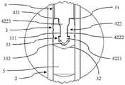
图1所示眼科预填充式注射器(PFS)1是根据本发明的注射器的第一实施例,其处于直立/竖立位置。PFS 1包括筒体2、止挡件3和柱塞4。筒体2基本上是圆柱形,其具有中空内部、孔口21和与孔口21相对的开口22。止挡件3位于筒体2的中空内部中,其在筒体2内部限定密封腔室5。更具体地,止挡件3具有顶部远侧面31和底部近侧面32,其中,腔室5位于近侧面32和筒体2的孔口21之间。孔口21具有喷口,其内部通道被封闭罩帽8紧密封闭。在孔口21周围,PFS 1配备有鲁尔锁适配器9。An ophthalmic pre-filled syringe (PFS) 1 shown in Figure 1 is a first embodiment of a syringe according to the present invention in an upright/erect position. The PFS 1 includes a
在腔室5内布置有液体眼科药物物质6。止挡件3可以在筒体2的内部移动,从而改变腔室5的容积。更具体地,通过使止挡件3朝着孔口21向下或向近侧移动,腔室5的容积减小,这允许在移除罩帽8之后将药物物质6从孔口21中排出。A liquid ophthalmic drug substance 6 is arranged in the
止挡件3还设计有内部空腔33。空腔33向上通向远侧面31。The
柱塞4具有竖直的圆柱形杆部分43,其延伸穿过筒体2的开口22进入其中空内部。它具有顶部远端41和底部近端42。远端41配备有具有肋的顶部手指推动表面。底端42包括基本上水平的抵接面421和从抵接面421沿着近侧方向向下延伸的倒钩422。如下文更详细所述,倒钩422位于止挡件3的空腔33内。The
PFS 1还具有延伸的/扩展的手指凸缘7,该手指凸缘7围绕筒体2的开口22夹在筒体2上。手指凸缘7允许方便地操作PFS 1。The PFS 1 also has an extended/expanded
在图2中更详细地示出了PFS 1在止挡件3周围的区段。因此,可以看出止挡件3的空腔33具有下部空腔部分或近侧空腔部分332和从远侧面31延伸到空腔部分332的上部通道部分或远侧通道部分331。倒钩422具有基本上与空腔33的空腔部分332相对应的近侧头部或下方头部4221和基本上与空腔33的通道部分331相对应的远侧颈部或上方颈部4222。止挡件3卡扣在柱塞4的倒钩422上,从而建立形状适配的连接。The section of the PFS 1 around the
柱塞4的近端42的倒钩422的颈部4222具有渐缩的第一压缩区段4223,止挡件3的空腔33的通道部分331具有定位在第一压缩区段4223周围的圆柱形第二压缩区段。因此,颈部4222的第一压缩区段4223向下方或向近侧比通道部分331的第二压缩区段渐缩程度更大,使得第一压缩区段4223周围的止挡件材料被压缩。The
这样,倒钩422的颈部4222的第一压缩区段4223与空腔33的通道331的第二压缩区段一起建立了密封结构,以密封止挡件3的空腔33,使其对微生物密封。In this way, the first
为了验证PFS 1的密封结构的功效,可以通过根据本发明的测试注射器的止挡件和柱塞之间的紧密度的方法的实施例进行测试。因此,该方法应用于未组装的PFS 1,并且包括以下步骤:例如通过在近侧面32中钻孔或通过切割一部分近侧面32,使止挡件3的空腔33的开口朝向近侧面32;通过筒体2的开口22将止挡件3布置到筒体2的中空内部中,使得止挡件3的远侧面31指向柱塞4;将氦检测器联接到筒体2的开口22,并通过筒体2的孔口21以约5毫巴的过压提供氦。氦检测器在止挡件3远侧测量氦浓度。因此,如果氦检测器未检测到任何氦,则PFS 1的密封结构气密地封闭空腔33。否则,通过测量到的氦浓度来评估封闭紧密度。In order to verify the efficacy of the sealing structure of the PFS 1, a test can be carried out by an embodiment of the method of testing the tightness between a stopper and a plunger of a syringe according to the present invention. Thus, the method is applied to an unassembled PFS 1 and comprises the steps of: orienting the opening of the
图3和图4所示另一眼科PFS 10是根据本发明的注射器的第二实施例,其处于直立位置。PFS 10与图1和图2的PFS 1在很大程度上同样地实现。具体地,它同样包括筒体20、止挡件30、腔室50、药物物质60、延伸的手指凸缘70、罩帽80和鲁尔锁适配器90,该筒体20具有孔口210和开口220,该止挡件30具有远侧面310、近侧面320和空腔330,该空腔330具有空腔部分3320和圆柱形通道部分3310。Another
柱塞40具有竖直的圆柱形杆部分430,其延伸穿过筒体20的开口220进入其中空内部。它具有顶部远端410和底部近端420。近端420包括基本上水平的抵接面4210和从抵接面4210沿着近侧方向向下延伸的倒钩4220。The
如图4所示,倒钩4220具有下方头部或近侧头部42210和基本上圆柱形的上方颈部或远侧颈部42220。颈部42220具有在抵接面4210和头部42210之间延伸的第一轴向长度42230。第一轴向长度42230小于止挡件30的空腔330的通道部分3310的在止挡件30的远侧面310和空腔330的空腔部分3320之间延伸的第二轴向长度。通过这些不同的第一和第二长度,当止挡件30卡在柱塞40的倒钩4220上时,止挡件30被压缩到柱塞40的抵接面4210上。As shown in FIG. 4, the
这样,倒钩4220的颈部42220的较短的第一轴向长度42230与止挡件30的空腔330的通道部分3310的第二轴向长度一起建立了密封结构。特别是,通过该结构,止挡件30的远侧面310被压缩到柱塞40的抵接面4210上,使得止挡件30的空腔330对微生物密封。In this way, the shorter first
图5和图6所示另一眼科PFS 19是根据本发明的注射器的第三实施例,其处于竖立位置。PFS 19与图1和图2的PFS 1以及图3和图4的PFS 10在很大程度上同样地实现。具体地,它同样包括筒体29、止挡件39、腔室59、药物物质69、延伸的手指凸缘79、罩帽89和鲁尔锁适配器99,该筒体29具有孔口219和开口229,该止挡件39具有远侧面319、近侧面329和空腔339,该空腔339具有空腔部分3329和圆柱形通道部分3319。Another
柱塞49具有竖直的圆柱形杆部分439,其延伸穿过筒体29的开口229进入其中空内部。它具有顶部远端419和底部近端429。近端429包括基本上水平的抵接面4219和从抵接面4219沿着近侧方向向下延伸的倒钩4229。The
如图6最佳所示,倒钩4229具有下方头部或近侧头部42219和基本上圆柱形的上方颈部或远侧颈部42229。柱塞49的倒钩4229卡在止挡件39的空腔339中,从而在柱塞49和止挡件39之间建立形状适配的连接。因此,倒钩4229的颈部42229位于空腔339的通道部分3319中,并且倒钩4229的头部42219位于空腔339的空腔部分3329中。As best seen in FIG. 6, the
在柱塞49的近端429的抵接面4219和止挡件39的远侧面319之间布置有垫圈42239。垫圈42239为环形,围绕倒钩4229的颈部42229延伸。倒钩4229的尺寸和形状确定成使得垫圈42239被压缩。这样,垫圈42239与倒钩4229一起建立了密封结构。通过这种密封结构,止挡件30的远侧面310被紧压到柱塞49的近端429上,使得止挡件30的空腔330对微生物密封。A
图示出本发明的各方面和实施例的本说明书和附图不应被视为限制了限定受保护的发明的权利要求。换言之,虽然已在附图和前面的说明中详细示出和描述了本发明,但这种图示和描述应被看作说明性的或示例性的而不是限制性的。可做出各种机械的、组成的、结构的、电气的和操作上的变更而不脱离此说明书和权利要求书的精神和范围。在一些情形中,未详细示出公知的电路、结构和技术,以免使本发明变得难以理解。因此,应理解的是,本领域普通技术人员可以在以下权利要求的范围和精神内作出变更和修改。特别地,本发明涵盖具有来自上文和下文描述的不同实施例的特征的任意组合的其它实施例。例如,可以以如下实施方式操作本发明,其中:The specification and drawings, which illustrate aspects and embodiments of the invention, should not be construed as limiting the claims defining the protected invention. In other words, while the invention has been shown and described in detail in the drawings and foregoing description, such illustration and description are to be regarded as illustrative or exemplary and not restrictive. Various mechanical, compositional, structural, electrical and operational changes may be made without departing from the spirit and scope of this description and claims. In some instances, well-known circuits, structures and techniques have not been shown in detail in order not to obscure the present invention. Therefore, it should be understood that changes and modifications within the scope and spirit of the following claims may occur to those of ordinary skill in the art. In particular, the invention covers further embodiments with any combination of features from the different embodiments described above and below. For example, the present invention can be operated in the following embodiments, wherein:
·图1和图2的PFS 1的密封结构与图3和图4的PFS 10的密封结构相组合。• The sealing structure of the PFS 1 of FIGS. 1 and 2 is combined with the sealing structure of the
·图1和图2的PFS 1的密封结构与图5和图6的PFS 19的密封结构相组合。• The sealing structure of the PFS 1 of FIGS. 1 and 2 is combined with the sealing structure of the
本公开还分别涵盖附图所示的所有其它特征,尽管它们在前面或下面的描述中可能未被描述。此外,可从本发明的主题或从所公开的主题放弃附图和说明书中描述的实施例的单一替代方案及其特征的单一替代方案。本公开包括由权利要求或示例性实施例中限定的特征组成的主题以及包含所述特征的主题。This disclosure also covers, respectively, all other features shown in the drawings, even though they may not be described in the preceding or following description. Furthermore, a single alternative of the embodiments and features described in the drawings and description may be disclaimed from the inventive subject matter or from the disclosed subject matter. The present disclosure includes subject matter consisting of the features defined in the claims or exemplary embodiments as well as subject matter incorporating said features.
此外,在权利要求书中,用语“包括”不排除其它要素或步骤,并且不定冠词“一”或“一个”不排除多个。单个单元或步骤可实现在权利要求中叙述的多个特征的功能。在相互不同的从属权利要求中叙述的特定措施的单纯事实并不表示这些措施的结合不能有利地使用。与定语或数值相结合的用语“基本上”、“约”、“大约”等特别是还分别明确地限定该定语或明确地限定该数值。给定数值或范围的上下文中的用语“约”指的是例如给定值或范围的20%以内、10%以内、5%以内或2%以内的值或范围。被描述为“联接”或“连接”的构件可以电气地或机械地直接联接,或者它们可经由一个或多个中间构件间接地联接。权利要求中的任何附图标记均不应被解释为限制保护范围。Furthermore, in the claims, the term "comprising" does not exclude other elements or steps, and the indefinite articles "a" or "an" do not exclude a plurality. A single unit or step may fulfill the functions of several features recited in the claims. The mere fact that certain measures are recited in mutually different dependent claims does not indicate that a combination of these measures cannot be used to advantage. The terms "substantially", "about", "approximately" etc. in conjunction with an attribute or a numerical value also specifically define the attribute or the numerical value, respectively. The term "about" in the context of a given value or range refers to, for example, a value or range within 20%, within 10%, within 5%, or within 2% of the given value or range. Components described as "coupled" or "connected" may be directly coupled, either electrically or mechanically, or they may be indirectly coupled via one or more intermediate components. Any reference signs in the claims shall not be construed as limiting the scope.
Claims (15)
Translated fromChineseApplications Claiming Priority (3)
| Application Number | Priority Date | Filing Date | Title |
|---|---|---|---|
| EP19213836 | 2019-12-05 | ||
| EP19213836.0 | 2019-12-05 | ||
| PCT/EP2020/084619WO2021110910A2 (en) | 2019-12-05 | 2020-12-04 | Syringe and tightness testing method |
Publications (1)
| Publication Number | Publication Date |
|---|---|
| CN115003262Atrue CN115003262A (en) | 2022-09-02 |
Family
ID=68806679
Family Applications (1)
| Application Number | Title | Priority Date | Filing Date |
|---|---|---|---|
| CN202080092093.9APendingCN115003262A (en) | 2019-12-05 | 2020-12-04 | Syringes and tightness test methods |
Country Status (5)
| Country | Link |
|---|---|
| US (1) | US20230010593A1 (en) |
| EP (1) | EP4069164A2 (en) |
| JP (1) | JP2023505488A (en) |
| CN (1) | CN115003262A (en) |
| WO (1) | WO2021110910A2 (en) |
Cited By (1)
| Publication number | Priority date | Publication date | Assignee | Title |
|---|---|---|---|---|
| CN118549055A (en)* | 2024-07-29 | 2024-08-27 | 常州医疗器材总厂股份有限公司 | Syringe leakproofness detecting system |
Families Citing this family (5)
| Publication number | Priority date | Publication date | Assignee | Title |
|---|---|---|---|---|
| EP3773821A1 (en) | 2018-03-27 | 2021-02-17 | Injecto Group A/S | Stopper with low force for use in an injector |
| CN114235310B (en)* | 2021-12-20 | 2024-02-13 | 深圳市优界科技有限公司 | Automatic syringe assembly detection equipment |
| CN119948326A (en)* | 2022-08-25 | 2025-05-06 | 豪夫迈·罗氏有限公司 | Container closure integrity testing method and system |
| CN116399860B (en)* | 2023-06-05 | 2025-06-27 | 北京明悟德生物技术有限公司 | Liquid phase working part with triple sealing cover |
| CN117054006B (en)* | 2023-10-10 | 2024-01-30 | 佳木斯大学 | Device and method for detecting sealing performance of needle tube of injector |
Citations (13)
| Publication number | Priority date | Publication date | Assignee | Title |
|---|---|---|---|---|
| US2895773A (en)* | 1956-10-22 | 1959-07-21 | Robert K Mcconnaughey | Variable diameter tensed ring piston |
| US4252118A (en)* | 1976-04-23 | 1981-02-24 | Jacques Richard | Non-reusable drug prefilled syringe assembly and method of use |
| EP0743072A2 (en)* | 1995-05-19 | 1996-11-20 | Becton, Dickinson and Company | Pre-fillable syringe and stopper assembly therefor |
| US20020013554A1 (en)* | 2000-07-28 | 2002-01-31 | Transcoject Gesellschaft Fur Medizinische Gerate Mbh & Co. Kg | Metering receptacle |
| US20070179442A1 (en)* | 2006-01-27 | 2007-08-02 | Ming-Jeng Shue | Single-use syringe |
| US20110137262A1 (en)* | 2009-12-04 | 2011-06-09 | Ivoclar Vivadent Ag | Application Device |
| WO2014155114A1 (en)* | 2013-03-26 | 2014-10-02 | Consort Medical Plc | Improved mixing syringe assembly |
| CN105188813A (en)* | 2013-03-12 | 2015-12-23 | 尤尼特拉克特注射器公司 | Retractable needle adapters and safety syringes |
| US20160144122A1 (en)* | 2014-11-26 | 2016-05-26 | Fisher Clinical Services GmbH | Syringe Assembly with Plunger Rod Backstop and Method of Use |
| US20170203043A1 (en)* | 2016-01-15 | 2017-07-20 | W. L. Gore & Associates, Inc. | Medical Delivery Device with Laminated Stopper |
| EP3216473A2 (en)* | 2016-02-26 | 2017-09-13 | Medimop Medical Projects Ltd. | Plunger with reduced leakage during storage |
| WO2019063786A1 (en)* | 2017-09-29 | 2019-04-04 | F. Hoffmann-La Roche Ag | Prefilled syringe and method of preparing a prefilled syringe |
| WO2019149869A2 (en)* | 2018-02-02 | 2019-08-08 | F. Hoffmann-La Roche Ag | Prefilled syringe and method of sterilizing a prefilled syringe |
Family Cites Families (21)
| Publication number | Priority date | Publication date | Assignee | Title |
|---|---|---|---|---|
| JPH09206377A (en)* | 1996-01-31 | 1997-08-12 | Daikyo Seiko:Kk | Syringe stopper |
| JP3387775B2 (en)* | 1997-05-22 | 2003-03-17 | 株式会社大協精工 | Sealing stopper for syringe and prefilled syringe |
| ITBO20060550A1 (en)* | 2006-07-21 | 2008-01-22 | Giuseppe Bonfiglioli | METHOD TO CHECK THE INTEGRITY OF STERILE SYRINGES. |
| JP2008241265A (en)* | 2007-03-23 | 2008-10-09 | Sumitomo Electric Ind Ltd | Airtight test method and airtight test collection container |
| ES2886499T3 (en)* | 2007-12-28 | 2021-12-20 | Terumo Corp | Sealing gasket for syringe and syringe comprising the sealing gasket |
| DE102008030271A1 (en)* | 2008-06-19 | 2009-12-31 | Arzneimittel Gmbh Apotheker Vetter & Co. Ravensburg | Device and method for testing the tightness of caps on medical hollow bodies |
| AU2009349190B2 (en)* | 2009-07-01 | 2013-03-14 | Wilco Ag | Method for leak testing closed, at least partially gas filled containers |
| CN102821804B (en)* | 2010-03-30 | 2015-06-10 | 泰尔茂株式会社 | Medical device with slideable coating, and syringe |
| PL3777834T3 (en)* | 2012-06-01 | 2022-05-30 | Novartis Ag | Syringe |
| AU2013100071C4 (en)* | 2012-07-03 | 2013-05-02 | Novartis Ag | Device |
| JOP20200175A1 (en) | 2012-07-03 | 2017-06-16 | Novartis Ag | Syringe |
| ITBO20130128A1 (en)* | 2013-03-26 | 2014-09-27 | Bonfiglioli Engineering S P A | METHOD AND APPARATUS FOR SYRINGE BODY VERIFICATION. |
| WO2017087871A1 (en)* | 2015-11-18 | 2017-05-26 | Sio2 Medical Products, Inc. | Pharmaceutical package for ophthalmic formulations |
| US10242437B2 (en)* | 2016-01-15 | 2019-03-26 | W. L. Gore & Associates, Inc. | Systems and methods for detecting syringe seal defects |
| WO2018142220A2 (en)* | 2017-02-03 | 2018-08-09 | Bee Sight Limited | Medical apparatus and method for sterilizing medical apparatus |
| US10493207B2 (en)* | 2017-02-27 | 2019-12-03 | W. L. Gore & Associates, Inc. | Medical delivery devices having low lubricant syringe barrels |
| CA3063995A1 (en)* | 2017-05-24 | 2018-11-29 | Sio2 Medical Products, Inc. | Sterilizable pharmaceutical package for ophthalmic formulations |
| CN112638450A (en)* | 2018-06-21 | 2021-04-09 | 西医药服务有限公司 | Plunger rod and assembly with improved thread geometry |
| JP2022504803A (en)* | 2018-10-15 | 2022-01-13 | エフ・ホフマン-ラ・ロシュ・アクチェンゲゼルシャフト | How to wrap syringe packs and prefilled syringes |
| WO2020165052A1 (en)* | 2019-02-12 | 2020-08-20 | Lonza Ltd | Displacement device, testing device and method for leakage testing of a connection of a tip cap with a syringe |
| US11067473B2 (en)* | 2019-06-07 | 2021-07-20 | Packaging Technologies & Inspection, LLC | System and method for high voltage leak detection |
- 2020
- 2020-12-04EPEP20816243.8Apatent/EP4069164A2/enactivePending
- 2020-12-04JPJP2022533378Apatent/JP2023505488A/enactivePending
- 2020-12-04USUS17/782,429patent/US20230010593A1/enactivePending
- 2020-12-04CNCN202080092093.9Apatent/CN115003262A/enactivePending
- 2020-12-04WOPCT/EP2020/084619patent/WO2021110910A2/ennot_activeCeased
Patent Citations (13)
| Publication number | Priority date | Publication date | Assignee | Title |
|---|---|---|---|---|
| US2895773A (en)* | 1956-10-22 | 1959-07-21 | Robert K Mcconnaughey | Variable diameter tensed ring piston |
| US4252118A (en)* | 1976-04-23 | 1981-02-24 | Jacques Richard | Non-reusable drug prefilled syringe assembly and method of use |
| EP0743072A2 (en)* | 1995-05-19 | 1996-11-20 | Becton, Dickinson and Company | Pre-fillable syringe and stopper assembly therefor |
| US20020013554A1 (en)* | 2000-07-28 | 2002-01-31 | Transcoject Gesellschaft Fur Medizinische Gerate Mbh & Co. Kg | Metering receptacle |
| US20070179442A1 (en)* | 2006-01-27 | 2007-08-02 | Ming-Jeng Shue | Single-use syringe |
| US20110137262A1 (en)* | 2009-12-04 | 2011-06-09 | Ivoclar Vivadent Ag | Application Device |
| CN105188813A (en)* | 2013-03-12 | 2015-12-23 | 尤尼特拉克特注射器公司 | Retractable needle adapters and safety syringes |
| WO2014155114A1 (en)* | 2013-03-26 | 2014-10-02 | Consort Medical Plc | Improved mixing syringe assembly |
| US20160144122A1 (en)* | 2014-11-26 | 2016-05-26 | Fisher Clinical Services GmbH | Syringe Assembly with Plunger Rod Backstop and Method of Use |
| US20170203043A1 (en)* | 2016-01-15 | 2017-07-20 | W. L. Gore & Associates, Inc. | Medical Delivery Device with Laminated Stopper |
| EP3216473A2 (en)* | 2016-02-26 | 2017-09-13 | Medimop Medical Projects Ltd. | Plunger with reduced leakage during storage |
| WO2019063786A1 (en)* | 2017-09-29 | 2019-04-04 | F. Hoffmann-La Roche Ag | Prefilled syringe and method of preparing a prefilled syringe |
| WO2019149869A2 (en)* | 2018-02-02 | 2019-08-08 | F. Hoffmann-La Roche Ag | Prefilled syringe and method of sterilizing a prefilled syringe |
Cited By (1)
| Publication number | Priority date | Publication date | Assignee | Title |
|---|---|---|---|---|
| CN118549055A (en)* | 2024-07-29 | 2024-08-27 | 常州医疗器材总厂股份有限公司 | Syringe leakproofness detecting system |
Also Published As
| Publication number | Publication date |
|---|---|
| JP2023505488A (en) | 2023-02-09 |
| US20230010593A1 (en) | 2023-01-12 |
| EP4069164A2 (en) | 2022-10-12 |
| WO2021110910A3 (en) | 2021-07-22 |
| WO2021110910A2 (en) | 2021-06-10 |
Similar Documents
| Publication | Publication Date | Title |
|---|---|---|
| CN115003262A (en) | Syringes and tightness test methods | |
| CN111670059B (en) | Prefilled syringe and method for sterilizing a prefilled syringe | |
| US12133963B2 (en) | Syringe pack and method of packing a prefilled syringe | |
| KR102659029B1 (en) | Tip cap assembly for closing an injection system | |
| US12220496B2 (en) | Prefilled syringe and method of preparing a prefilled syringe | |
| US12296138B2 (en) | Prefilled syringe and method of preparing a prefilled syringe | |
| KR102494471B1 (en) | Device and method for overfilling drug containers | |
| CZ284900B6 (en) | In advance filled syringe for storage and discharge of a liquid and sterile therapeutic substance | |
| US11944791B2 (en) | Multi-use drug delivery device for drugs with less preservatives | |
| HK40074264A (en) | Syringe and tightness testing method | |
| CN107635528A (en) | Devices for reconstituting and administering drugs | |
| HK40036582A (en) | Prefilled syringe and method of sterilizing a prefilled syringe | |
| HK40030201B (en) | Prefilled syringe and method of preparing a prefilled syringe | |
| HK40030201A (en) | Prefilled syringe and method of preparing a prefilled syringe | |
| HK40030217A (en) | Prefilled syringe and method of preparing a prefilled syringe |
Legal Events
| Date | Code | Title | Description |
|---|---|---|---|
| PB01 | Publication | ||
| PB01 | Publication | ||
| SE01 | Entry into force of request for substantive examination | ||
| SE01 | Entry into force of request for substantive examination | ||
| REG | Reference to a national code | Ref country code:HK Ref legal event code:DE Ref document number:40074264 Country of ref document:HK |