CN114967352A - Antifouling device - Google Patents
Antifouling deviceDownload PDFInfo
- Publication number
- CN114967352A CN114967352ACN202110220311.9ACN202110220311ACN114967352ACN 114967352 ACN114967352 ACN 114967352ACN 202110220311 ACN202110220311 ACN 202110220311ACN 114967352 ACN114967352 ACN 114967352A
- Authority
- CN
- China
- Prior art keywords
- fouling
- antifouling
- extraction
- light
- channel
- Prior art date
- Legal status (The legal status is an assumption and is not a legal conclusion. Google has not performed a legal analysis and makes no representation as to the accuracy of the status listed.)
- Pending
Links
Images


Classifications
- G—PHYSICS
- G03—PHOTOGRAPHY; CINEMATOGRAPHY; ANALOGOUS TECHNIQUES USING WAVES OTHER THAN OPTICAL WAVES; ELECTROGRAPHY; HOLOGRAPHY
- G03F—PHOTOMECHANICAL PRODUCTION OF TEXTURED OR PATTERNED SURFACES, e.g. FOR PRINTING, FOR PROCESSING OF SEMICONDUCTOR DEVICES; MATERIALS THEREFOR; ORIGINALS THEREFOR; APPARATUS SPECIALLY ADAPTED THEREFOR
- G03F7/00—Photomechanical, e.g. photolithographic, production of textured or patterned surfaces, e.g. printing surfaces; Materials therefor, e.g. comprising photoresists; Apparatus specially adapted therefor
- G03F7/70—Microphotolithographic exposure; Apparatus therefor
- G03F7/708—Construction of apparatus, e.g. environment aspects, hygiene aspects or materials
- G03F7/70908—Hygiene, e.g. preventing apparatus pollution, mitigating effect of pollution or removing pollutants from apparatus
- G03F7/70916—Pollution mitigation, i.e. mitigating effect of contamination or debris, e.g. foil traps
- G—PHYSICS
- G03—PHOTOGRAPHY; CINEMATOGRAPHY; ANALOGOUS TECHNIQUES USING WAVES OTHER THAN OPTICAL WAVES; ELECTROGRAPHY; HOLOGRAPHY
- G03F—PHOTOMECHANICAL PRODUCTION OF TEXTURED OR PATTERNED SURFACES, e.g. FOR PRINTING, FOR PROCESSING OF SEMICONDUCTOR DEVICES; MATERIALS THEREFOR; ORIGINALS THEREFOR; APPARATUS SPECIALLY ADAPTED THEREFOR
- G03F7/00—Photomechanical, e.g. photolithographic, production of textured or patterned surfaces, e.g. printing surfaces; Materials therefor, e.g. comprising photoresists; Apparatus specially adapted therefor
- G03F7/70—Microphotolithographic exposure; Apparatus therefor
- G03F7/708—Construction of apparatus, e.g. environment aspects, hygiene aspects or materials
- G03F7/70908—Hygiene, e.g. preventing apparatus pollution, mitigating effect of pollution or removing pollutants from apparatus
Landscapes
- Health & Medical Sciences (AREA)
- Epidemiology (AREA)
- Public Health (AREA)
- Life Sciences & Earth Sciences (AREA)
- Atmospheric Sciences (AREA)
- Engineering & Computer Science (AREA)
- Environmental & Geological Engineering (AREA)
- Physics & Mathematics (AREA)
- General Physics & Mathematics (AREA)
- Exposure And Positioning Against Photoresist Photosensitive Materials (AREA)
Abstract
Translated fromChinese
Description
Translated fromChinese技术领域technical field
本发明涉及光刻技术领域,尤其涉及一种防污装置。The invention relates to the technical field of photolithography, and in particular, to an antifouling device.
背景技术Background technique
光刻是通过曝光将硅晶圆表面薄膜的特定部分除去的工艺,光刻生产的目标是根据电路设计的要求,生成尺寸精确的特征图形。光刻机在曝光过程中,硅晶圆表面的光刻胶中的有机溶剂会受热挥发,但挥发的有机物会粘附在物镜的镜片上,时间长了便会降低物镜的透光率,影响后续光刻质量,增加了维修工时和成本。Lithography is a process of removing specific parts of the thin film on the surface of a silicon wafer by exposure. The goal of lithography production is to generate dimensionally accurate feature patterns according to the requirements of circuit design. During the exposure process of the lithography machine, the organic solvent in the photoresist on the surface of the silicon wafer will be volatilized by heat, but the volatilized organic matter will adhere to the lens of the objective lens, which will reduce the light transmittance of the objective lens for a long time, affecting the The quality of subsequent lithography increases maintenance man-hours and costs.
现有技术中在物镜的下方装配吹气装置,吹气装置将气体由一侧吹向另一侧,以形成一层保护气帘来隔离物镜和硅晶圆,进而达到防止物镜污染的目的。但是这种方式下仅通过隔离物镜与硅晶圆来实现防污,气体的分布极易不均,光刻过程污染物的挥发又较大,因此气帘的完整性和隔离效果有限,经常会出现部分区域无气帘隔离进而造成镜片的局部污染,有时甚至会加速镜片及其光刻机整机的污染,使得防污效果不佳,降低了产品良品率。In the prior art, an air blowing device is installed below the objective lens, and the air blowing device blows gas from one side to the other side to form a protective air curtain to isolate the objective lens and the silicon wafer, thereby preventing contamination of the objective lens. However, in this way, only by isolating the objective lens and the silicon wafer to achieve anti-fouling, the gas distribution is very easy to be uneven, and the volatilization of pollutants in the lithography process is relatively large. Therefore, the integrity and isolation effect of the air curtain are limited, and often occur There is no air curtain isolation in some areas, which causes local pollution of the lens, and sometimes even accelerates the pollution of the lens and the entire lithography machine, which makes the anti-fouling effect poor and reduces the product yield.
发明内容SUMMARY OF THE INVENTION
本发明的目的在于提供一种防污装置,能够有效隔离镜片与待光刻件,同时进行污染物的抽离,提升防污效果,提高成像质量和产品良品率。The purpose of the present invention is to provide an anti-fouling device, which can effectively isolate the lens and the part to be lithographic, and simultaneously extract the pollutants, improve the anti-fouling effect, and improve the imaging quality and product yield.
为实现上述目的,提供以下技术方案:To achieve the above purpose, the following technical solutions are provided:
一种防污装置,能够置于待光刻件与物镜之间,所述防污装置包括:An anti-fouling device, which can be placed between a to-be-photographed piece and an objective lens, the anti-fouling device comprising:
防污本体,呈环形结构,所述防污本体具有沿第一方向间隔设置的第一侧和第二侧,且所述第一侧相对于所述第二侧更靠近所述待光刻件;所述防污本体的所述第一侧与所述待光刻件之间为间隙配合;An anti-fouling body, in the form of a ring structure, the anti-fouling body has a first side and a second side spaced along a first direction, and the first side is closer to the to-be-lithography part than the second side ; There is a clearance fit between the first side of the antifouling body and the to-be-photolithographic piece;
透光件,所述防污本体的中心形成有中空的透光部,所述透光件封闭所述透光部,所述物镜的光通过所述透光件透射至所述待光刻件上;A light-transmitting part, a hollow light-transmitting part is formed in the center of the anti-fouling body, the light-transmitting part closes the light-transmitting part, and the light of the objective lens is transmitted to the to-be-lithography part through the light-transmitting part superior;
抽排组件,包括开设于所述防污本体的所述第一侧的多个抽风孔和设于所述防污本体内部的抽排通道,所述抽风孔与所述抽排通道相连通,所述待光刻件周围的污染物依次经由所述抽风孔和所述抽排通道被抽至外界。The suction and discharge assembly includes a plurality of air suction holes opened on the first side of the anti-fouling body and a suction and discharge channel arranged inside the anti-fouling body, and the suction holes are communicated with the suction and discharge channel, The contaminants around the part to be photoetched are drawn to the outside through the air suction hole and the suction channel in sequence.
可选地,所述防污本体的所述第一侧与所述待光刻件之间的间隙小于1mm。Optionally, the gap between the first side of the antifouling body and the part to be photoetched is less than 1 mm.
可选地,多个所述抽风孔位于以所述待光刻件的中心为圆心的同一虚拟圆上;所述虚拟圆的半径大于所述待光刻件的半径。Optionally, a plurality of the ventilation holes are located on the same virtual circle with the center of the part to be photoetched as the center; the radius of the virtual circle is larger than the radius of the part to be photoetched.
可选地,所述抽排通道为与所述虚拟圆同心的环形结构。Optionally, the evacuation channel is an annular structure concentric with the virtual circle.
可选地,所述抽排通道位于所述抽风孔沿所述第一方向的上方。Optionally, the extraction channel is located above the air extraction hole along the first direction.
可选地,所述抽排组件设置有一组,且位于所述防污本体的内圈处;或Optionally, one set of the suction and discharge assemblies is provided, and is located at the inner ring of the antifouling body; or
所述抽排组件设置有两组,且分别位于所述防污本体的内圈和外圈处。There are two groups of the suction and discharge assemblies, and they are located at the inner ring and the outer ring of the antifouling body respectively.
可选地,所述抽排组件还包括抽风口,所述抽排通道通过所述抽风口与外界连通。Optionally, the air extraction assembly further includes an air extraction port, and the air extraction channel communicates with the outside through the air extraction port.
可选地,所述抽风口与所述抽排通道通过连通通道相连通。Optionally, the air extraction port is communicated with the extraction channel through a communication channel.
可选地,所述抽风口设于所述防污本体的外周壁上;所述连通通道沿所述防污本体的径向延伸。Optionally, the air suction port is provided on the outer peripheral wall of the antifouling body; the communication channel extends along the radial direction of the antifouling body.
可选地,所述抽风口设置有多个,多个所述抽风口在所述防污本体上呈中心对称分布。Optionally, a plurality of the air suction ports are provided, and the plurality of the air suction ports are centrally symmetrically distributed on the antifouling body.
可选地,所述抽风孔的延伸方向与所述待光刻件呈夹角设置,且所述夹角大于0度小于180度。Optionally, the extension direction of the air extraction hole is set at an included angle with the to-be-lithography piece, and the included angle is greater than 0 degrees and less than 180 degrees.
与现有技术相比,本发明的有益效果:Compared with the prior art, the beneficial effects of the present invention:
通过防污本体与透光件装配形成的整体,使得待光刻件与物镜之间通过实体结构进行充分的物理隔离,相对于气帘式隔离方式,能够充分避免污染物与镜片接触;同时设置抽排组件以对污染物进行抽离,从根源上减少待光刻件周围的污染物含量,进一步避免了污染物扩散至上方物镜或光刻机其它位置,整个防污装置结构简单,防污效果显著;透光件使物镜的光能够顺利通过透光件射在待光刻件上,保证曝光功能的正常实现。Through the assembly formed by the anti-fouling body and the light-transmitting part, the physical structure between the part to be etched and the objective lens is fully physically isolated. Compared with the air curtain isolation method, the contact between the contaminants and the lens can be fully avoided; Arranging components to extract contaminants, reducing the contaminant content around the parts to be lithography from the root cause, further avoiding the spread of contaminants to the upper objective lens or other positions of the lithography machine. Remarkable; the light-transmitting part enables the light of the objective lens to pass through the light-transmitting part smoothly and radiate on the part to be lithography, so as to ensure the normal realization of the exposure function.
附图说明Description of drawings
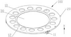
图1为本发明实施例中防污装置在第一视角下的结构示意图;1 is a schematic structural diagram of an antifouling device in a first viewing angle according to an embodiment of the present invention;
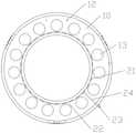
图2为本发明实施例中防污装置在第二视角下的结构示意图;2 is a schematic structural diagram of an antifouling device in a second viewing angle according to an embodiment of the present invention;
图3为本发明实施例中防污装置的仰视示意图;Fig. 3 is the bottom view schematic diagram of the antifouling device in the embodiment of the present invention;
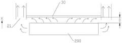
图4为本发明实施例中污染物的流向示意图;4 is a schematic diagram of the flow direction of pollutants in the embodiment of the present invention;
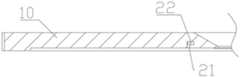
图5为本发明实施例中防污本体部分结构的第一截面示意图;FIG. 5 is a first cross-sectional schematic diagram of a partial structure of an antifouling body in an embodiment of the present invention;
图6为本发明实施例中防污本体部分结构的第二截面示意图。FIG. 6 is a second schematic cross-sectional view of the partial structure of the antifouling body in the embodiment of the present invention.
附图标记:Reference number:
100、防污装置;200、待光刻件;100. Antifouling device; 200. Parts to be lithography;
10、防污本体;20、抽排组件;30、透光件;10. Anti-fouling body; 20. Extraction components; 30. Light-transmitting parts;
11、第一定位部;12、连接部;13、减重孔;14、定位凸台;21、抽风孔;22、抽排通道;23、抽风口;24、连通通道。11, the first positioning part; 12, the connecting part; 13, the weight reduction hole; 14, the positioning boss; 21, the ventilation hole; 22, the exhaust channel;
具体实施方式Detailed ways
为使本发明实施例的目的、技术方案和优点更加清楚,下面将结合本发明实施例中的附图,对本发明实施例中的技术方案进行清楚、完整地描述,显然,所描述的实施例是本发明一部分实施例,而不是全部的实施例。通常在此处附图中描述和示出的本发明实施例的组件可以以各种不同的配置来布置和设计。In order to make the purposes, technical solutions and advantages of the embodiments of the present invention clearer, the technical solutions in the embodiments of the present invention will be clearly and completely described below with reference to the accompanying drawings in the embodiments of the present invention. Obviously, the described embodiments These are some embodiments of the present invention, but not all embodiments. The components of the embodiments of the invention generally described and illustrated in the drawings herein may be arranged and designed in a variety of different configurations.
因此,以下对在附图中提供的本发明的实施例的详细描述并非旨在限制要求保护的本发明的范围,而是仅仅表示本发明的选定实施例。基于本发明中的实施例,本领域普通技术人员在没有作出创造性劳动前提下所获得的所有其他实施例,都属于本发明保护的范围。Thus, the following detailed description of the embodiments of the invention provided in the accompanying drawings is not intended to limit the scope of the invention as claimed, but is merely representative of selected embodiments of the invention. Based on the embodiments of the present invention, all other embodiments obtained by those of ordinary skill in the art without creative efforts shall fall within the protection scope of the present invention.
应注意到:相似的标号和字母在下面的附图中表示类似项,因此,一旦某一项在一个附图中被定义,则在随后的附图中不需要对其进行进一步定义和解释。It should be noted that like numerals and letters refer to like items in the following figures, so once an item is defined in one figure, it does not require further definition and explanation in subsequent figures.
在本发明的描述中,需要说明的是,术语“上”、“下”、“左”、“右”、“竖直”、“水平”、“内”、“外”等指示的方位或位置关系为基于附图所示的方位或位置关系,或者是该发明产品使用时惯常摆放的方位或位置关系,仅是为了便于描述本发明和简化描述,而不是指示或暗示所指的装置或元件必须具有特定的方位、以特定的方位构造和操作,因此不能理解为对本发明的限制。此外,术语“第一”、“第二”、“第三”等仅用于区分描述,而不能理解为指示或暗示相对重要性。在本发明的描述中,除非另有说明,“多个”的含义是两个或两个以上。In the description of the present invention, it should be noted that the terms "upper", "lower", "left", "right", "vertical", "horizontal", "inner", "outer", etc. indicate the orientation or The positional relationship is based on the orientation or positional relationship shown in the accompanying drawings, or the orientation or positional relationship that the product of the invention is usually placed when it is used. It is only for the convenience of describing the present invention and simplifying the description, rather than indicating or implying the device referred to. Or elements must have a particular orientation, be constructed and operate in a particular orientation, and therefore should not be construed as limiting the invention. Furthermore, the terms "first", "second", "third", etc. are only used to differentiate the description and should not be construed as indicating or implying relative importance. In the description of the present invention, unless otherwise specified, "plurality" means two or more.
在本发明的描述中,还需要说明的是,除非另有明确的规定和限定,术语“设置”、“连接”应做广义理解,例如,可以是固定连接,也可以是可拆卸连接,或一体地连接;可以是机械连接,也可以是电连接。对于本领域的普通技术人员而言,可以具体情况理解上述术语在本发明中的具体含义。In the description of the present invention, it should also be noted that, unless otherwise expressly specified and limited, the terms "arrangement" and "connection" should be understood in a broad sense, for example, it may be a fixed connection or a detachable connection, or Integrally connected; either mechanical or electrical. For those of ordinary skill in the art, the specific meanings of the above terms in the present invention can be understood in specific situations.
在本发明中,除非另有明确的规定和限定,第一特征在第二特征之“上”或之“下”可以包括第一和第二特征直接接触,也可以包括第一和第二特征不是直接接触而是通过它们之间的另外的特征接触。而且,第一特征在第二特征“之上”、“上方”和“上面”包括第一特征在第二特征正上方和斜上方,或仅仅表示第一特征水平高度高于第二特征。第一特征在第二特征“之下”、“下方”和“下面”包括第一特征在第二特征正下方和斜下方,或仅仅表示第一特征水平高度小于第二特征。In the present invention, unless otherwise expressly specified and limited, a first feature "on" or "under" a second feature may include the first and second features in direct contact, or may include the first and second features Not directly but through additional features between them. Also, the first feature being "above", "over" and "above" the second feature includes the first feature being directly above and obliquely above the second feature, or simply means that the first feature is level higher than the second feature. The first feature is "below", "below" and "below" the second feature includes the first feature being directly below and diagonally below the second feature, or simply means that the first feature has a lower level than the second feature.
下面详细描述本发明的实施例,所述实施例的示例在附图中示出,其中自始至终相同或类似的标号表示相同或类似的元件或具有相同或类似功能的元件。下面通过参考附图描述的实施例是示例性的,仅用于解释本发明,而不能理解为对本发明的限制。The following describes in detail the embodiments of the present invention, examples of which are illustrated in the accompanying drawings, wherein the same or similar reference numerals refer to the same or similar elements or elements having the same or similar functions throughout. The embodiments described below with reference to the accompanying drawings are exemplary, only used to explain the present invention, and should not be construed as a limitation of the present invention.
如图1-6所示,本实施例在于提供一种防污装置,其能够置于待光刻件200和物镜之间,用于防止光刻过程中的污染物扩散至物镜或光刻机的其它位置;具体地,防污装置100包括防污本体10、抽排组件20及透光件30;防污本体10为环形结构,且具有沿第一方向间隔设置的第一侧和第二侧,且第一侧相对于第二侧更靠近待光刻件200;防污本体10的第一侧与待光刻件200之间为间隙配合;防污本体10的中心形成有中空的透光部,透光件30封闭透光部,物镜的光通过透光件30透射至待光刻件200上;抽排组件20包括开设于防污本体10的第一侧的多个抽风孔21和设于防污本体10内部的抽排通道22,抽风孔21与抽排通道22相连通,待光刻件200周围的污染物依次经由抽风孔21和抽排通道22被抽至外界。防污本体10为具有一定厚度的板状结构,以方便在防污本体10的内部开设抽排通道22;本实施例中所指的第一方向即防污本体10的板厚方向,在附图中即为X向。As shown in FIGS. 1-6 , the present embodiment provides an anti-fouling device, which can be placed between the object to be
本实施例的防污装置100先通过防污本体10与透光件30装配形成的整体,使得待光刻件200与物镜之间通过实体结构进行充分的物理隔离,相对于气帘式隔离方式,能够充分避免污染物与镜片接触,不会出现局部区域未能隔离的情况,保证了隔离的完整性和充分性;同时设置抽排组件20对污染物进行抽离,从根源上减少待光刻件200周围的污染物含量,进一步避免了污染物扩散至上方物镜或光刻机其它位置,整个防污装置100结构简单,防污效果显著;透光件30使物镜的光能够顺利通过透光件30透射在待光刻件200上,保证曝光功能的正常实现。The
具体实施时,当待光刻件200需要曝光时,防污装置100由外部设备移至物镜与待光刻件200之间,使得防污本体10的第一侧与待光刻件200之间具有足够小的间隙;物镜透过透光件30对待光刻件200进行曝光操作,产生的挥发性有机物被防污本体10及透光件30隔离,同步地,抽排组件20工作,将污染物抽离出去;待曝光结束,再利用外部设备将防污装置100由物镜与待光刻件200之间移出去,不干涉光刻机的下一步操作。曝光过程中,待光刻件200与防污装置100之间的气体只存在向外的抽离,因此会在二者之间形成一定的负压,但由于曝光时间较短,该负压较小,对周围的压强影响也较小,既不会对待光刻件200与防污装置100之间的位置关系及间隙造成影响,也不会对光路的传播造成影响,即本实施例的防污装置100能够在确保光刻机正常曝光的同时,顺利地将污染物抽离出去。可选地,参考图4,防污本体10的第一侧与待光刻件200之间的间隙D小于1mm,该间隙能够保证抽排组件20将污染物抽出来的同时,还能有效抑制污染物自身向外的扩散,使得防污效果达到最佳。进一步地,防污本体10的第二侧与物镜的底面之间的距离为5-10mm,以确保不会发生干涉。具体实施时,防污装置100一般是直接放置于待光刻件200的工作台上,为了确保防污装置100与待光刻件200之间具有间隙,参考图2,可在防污本体10的第一侧的外边缘设置一圈定位凸台14;安装防污装置100时,定位凸台14与工作台抵接使整个防污装置100支撑于工作台上,待光刻件200自然与防污本体10主体的第一侧形成有间隙,避免了防污本体10与待光刻件200发生紧密贴合,影响污染气体的逸出。In a specific implementation, when the part to be photoetched 200 needs to be exposed, the
参考图1和图2,防污本体10的第一侧上设置有第一定位部11,待光刻件200的工作台上设置第二定位部,通过第一定位部11与第二定位部的配合,能够实现防污装置100在工作台上的定位,进而确保每次放置时防污装置100的位置固定。可选地,本实施例中,第一定位部11和第二定位部分别为卡凸和卡槽。进一步地,防污本体10上还设置连接部12,用于与外部设备建立连接,进而由外部设备带动防污本体10移动;本实施例中,连接部12为设于防污本体10上的安装孔。由于本实施例的防污装置100是单独置于物镜下方的,不用单独装配到物镜上,且实现了污染物根源上的去除,因此能够实现光刻机内部整体的污染控制,而不单单针对物镜,具体实施时既可以单独使用,也可以将其与现有的物镜上配置的吹气装置进行配合,充分实现防污。Referring to FIGS. 1 and 2 , a
待光刻件200一般均为硅晶圆,即为圆形结构,则本实施例中,防污本体10和透光件30也相应地设为圆形结构,且待光刻件200、防污本体10和透光件30的中轴线均相互重合。进一步地,透光件30连接于防污本体10的内周壁上,以尽可能地压缩防污装置100的厚度,避免厚度过大影响光刻机其它元件的设置。进一步地,参考图2和图3,多个抽风孔21位于以待光刻件200的中心为圆心的同一虚拟圆上,由于待光刻件200为圆形结构,其中心即为圆心,因此将抽风孔21设置为沿着与待光刻件200同一圆心的虚拟圆分布,能够与待光刻件200的结构相对应,方便就近对待光刻件200周边的污染物抽离。进一步地,多个抽风孔21沿虚拟圆的周向呈均匀分布,以提高抽离的均匀性。可以理解的是,在满足防污本体10自身强度的条件下,抽风孔21的设置越多越好,以保证抽离效率。更进一步地,参考图4,虚拟圆的半径大于待光刻件200的半径,即抽风孔21设置在待光刻件200外周,使虚拟圆在防污本体10厚度方向上的投影覆盖住整个待光刻件200,由于污染物不仅存在于待光刻件200的正上方,还会部分逃逸到待光刻件200外边缘,因此上述设置还使此处的污染物也能得到抽离。The parts to be photoetched 200 are generally silicon wafers, that is, a circular structure. In this embodiment, the
可选地,参考图3,抽排通道22为与虚拟圆同圆心的环形结构,方便与各个抽风孔21进行统一连通,各个抽风孔21抽上来的含有污染物的气体同步汇集至同一抽排通道22,由抽排通道22统一抽离。进一步可选地,本实施例中,抽排通道22位于抽风孔21沿第一方向的上方,以达到充分利用防污本体10厚度尺寸的目的。Optionally, referring to FIG. 3 , the
本实施例中,抽排组件20设有一个,且位于防污本体10的内圈处,由于待光刻件200的尺寸与透光件30的尺寸基本相当,因此上述抽排组件20的位置设置实现了将抽风孔21设于待光刻件200的外周的同时,还使其不会过分远离待光刻件200,在污染物进行更大范围的扩散之前,对其进行抽排操作。在一些其他的实施例中,抽排组件20设置有两个,且分别位于防污本体10的内圈和外圈处,由上面叙述可知,虽然在防污本体10内圈设置一组抽排组件20可以实现污染物的大部分抽离,但是仍然可能存在一部分污染物已经扩散至较远范围,因此,通过在防污本体10的外圈处增设一组抽排组件20,能够实现这部分污染物的抽离,提高了防污效果。当然还可以在上述两个抽排组件20之间再增设抽排组件20,抽排组件20越多,对污染物的抽离效果自然越好。In this embodiment, one
进一步地,参考图2和图3,抽排组件20还包括抽风口23,抽排通道22通过抽风口23与外界连通,抽风口23的设置用于方便外界提供抽排组件20的抽排动力。具体地,在抽风口23处设置有气管接头,气管接头用于连接气管,抽排动力通过气管传递至抽风口23、进一步传递至抽排通道22和抽风孔21,实现污染物的抽离。可选地,气管接头选用万向气管接头。可选地,抽风口23设于防污本体10的第二侧,并直接与抽排通道22连通。本实施例中,抽风口23设于防污本体10的外周壁上,优化了防污装置100结构,避免占用竖直空间,干扰正常曝光。进一步地,抽风口23与抽排通道22之间通过连通通道24连通。具体地,当抽风口23设于外周壁上时,连通通道24沿防污本体10的径向延伸,使气体流通路径越短越好,方便实现快速抽气。对于设置有两组或两组以上抽排组件20的防污装置100来说,可以通过同一连通通道24将所有的抽排通道22连接于同一抽风口23,即连通通道24沿径向连通多个抽排通道22,使得一个抽风口23的抽排动力可以同时传递至多个抽排通道22处,实现多个抽排组件20的抽排。进一步地,抽风口23可以根据需要设置多个,多个抽风口23在防污本体10上呈中心对称分布,确保对污染物充分且均匀的抽离。当设置多个抽风口23时,相应的连通通道24也设置多个;抽风口23与连通通道24为一一对应设置。Further, referring to FIG. 2 and FIG. 3 , the extraction and
可选地,抽风孔21可以为矩形、弧形或圆形结构。更进一步地,抽风孔21的延伸方向与待光刻件200呈夹角设置,且夹角大于0度小于180度;实际制造时,根据抽风孔21所在的虚拟圆半径和待光刻件200的半径合理安排抽风孔21的延伸方向,确保气流能够尽可能顺利且平滑地进入抽风孔21,提升污染物抽离效果。Optionally, the ventilation holes 21 may be rectangular, arcuate or circular. Further, the extension direction of the
防污本体10采用不锈钢材料制成,以确保有足够的刚度。进一步地,参考图1-3,在防污本体10上还设置多个减重孔13,以减轻整个防污装置100的重量,方便防污装置100的移动。减重孔13沿第一方向贯穿整个防污本体10,且位于防污本体10的内周壁和外周壁之间。可选地,多个减重孔13沿着防污本体10的周向均匀分布。The
注意,上述仅为本发明的较佳实施例及所运用技术原理。本领域技术人员会理解,本发明不限于这里所述的特定实施例,对本领域技术人员来说能够进行各种明显的变化、重新调整和替代而不会脱离本发明的保护范围。因此,虽然通过以上实施例对本发明进行了较为详细的说明,但是本发明不仅仅限于以上实施例,在不脱离本发明构思的情况下,还可以包括更多其他等效实施例,而本发明的范围由所附的权利要求范围决定。Note that the above are only preferred embodiments of the present invention and applied technical principles. Those skilled in the art will understand that the present invention is not limited to the specific embodiments described herein, and various obvious changes, readjustments and substitutions can be made by those skilled in the art without departing from the protection scope of the present invention. Therefore, although the present invention has been described in detail through the above embodiments, the present invention is not limited to the above embodiments, and can also include more other equivalent embodiments without departing from the concept of the present invention. The scope is determined by the scope of the appended claims.
Claims (11)
Priority Applications (1)
| Application Number | Priority Date | Filing Date | Title |
|---|---|---|---|
| CN202110220311.9ACN114967352A (en) | 2021-02-26 | 2021-02-26 | Antifouling device |
Applications Claiming Priority (1)
| Application Number | Priority Date | Filing Date | Title |
|---|---|---|---|
| CN202110220311.9ACN114967352A (en) | 2021-02-26 | 2021-02-26 | Antifouling device |
Publications (1)
| Publication Number | Publication Date |
|---|---|
| CN114967352Atrue CN114967352A (en) | 2022-08-30 |
Family
ID=82973425
Family Applications (1)
| Application Number | Title | Priority Date | Filing Date |
|---|---|---|---|
| CN202110220311.9APendingCN114967352A (en) | 2021-02-26 | 2021-02-26 | Antifouling device |
Country Status (1)
| Country | Link |
|---|---|
| CN (1) | CN114967352A (en) |
Citations (3)
| Publication number | Priority date | Publication date | Assignee | Title |
|---|---|---|---|---|
| CN107783283A (en)* | 2016-08-30 | 2018-03-09 | 上海微电子装备(集团)股份有限公司 | Eyeglass environmental control system and method |
| CN109283797A (en)* | 2017-07-21 | 2019-01-29 | 上海微电子装备(集团)股份有限公司 | Object lens protective device, objective system and lithographic equipment |
| CN110764368A (en)* | 2018-07-27 | 2020-02-07 | 上海微电子装备(集团)股份有限公司 | Objective contamination prevention device |
- 2021
- 2021-02-26CNCN202110220311.9Apatent/CN114967352A/enactivePending
Patent Citations (4)
| Publication number | Priority date | Publication date | Assignee | Title |
|---|---|---|---|---|
| CN107783283A (en)* | 2016-08-30 | 2018-03-09 | 上海微电子装备(集团)股份有限公司 | Eyeglass environmental control system and method |
| US20190187561A1 (en)* | 2016-08-30 | 2019-06-20 | Shanghai Micro Electronics Equipment (Group) Co., Ltd. | Lens contamination prevention device and method |
| CN109283797A (en)* | 2017-07-21 | 2019-01-29 | 上海微电子装备(集团)股份有限公司 | Object lens protective device, objective system and lithographic equipment |
| CN110764368A (en)* | 2018-07-27 | 2020-02-07 | 上海微电子装备(集团)股份有限公司 | Objective contamination prevention device |
Similar Documents
| Publication | Publication Date | Title |
|---|---|---|
| TWI639062B (en) | Lens anti-pollution device and method | |
| KR101061696B1 (en) | Coating film forming apparatus and coating film forming method | |
| CN112593208B (en) | Semiconductor processing equipment | |
| CN115312432A (en) | Semiconductor process equipment | |
| TW201921129A (en) | Objective lens protection device, objective lens system and lithographic device | |
| WO2020024837A1 (en) | Device for operating substrate | |
| CN114967352A (en) | Antifouling device | |
| CN116507069A (en) | Digital control cabinet for multi-span greenhouse | |
| CN110764368A (en) | Objective contamination prevention device | |
| CN211929459U (en) | Vacuum adsorption device | |
| CN210954613U (en) | Lens pollution prevention and control device, LDI lens and LDI equipment | |
| TWM527792U (en) | Cleaning system and wafer box thereof | |
| CN218123349U (en) | A reaction chamber protective shell and plasma etching equipment | |
| CN210934130U (en) | Clean rubber coating developing device | |
| CN210159894U (en) | Spin coater tray and spin coater | |
| CN215896337U (en) | Graphite boat with evaporation holes | |
| CN120438829A (en) | Pollutant pumping device and laser annealing equipment | |
| CN111594812A (en) | A simple shading exhaust device and stage lamp with the same | |
| CN216711911U (en) | Cooling device and cooling system of glass tube | |
| CN217884260U (en) | Heat radiation structure and satellite communication equipment | |
| CN115145122B (en) | Objective lens anti-pollution device | |
| CN221615084U (en) | Dustproof device of switch | |
| CN115145122A (en) | An objective lens anti-pollution device | |
| CN201117643Y (en) | Semiconductor device storage device and photomask storage device | |
| TW202403466A (en) | Lithography machine, pollution prevention device for illumination lamp chamber, and design method thereof which a uniform air flow field can be formed on both surfaces of the optical glass, achieving protection of both sides of the optical glass surface |
Legal Events
| Date | Code | Title | Description |
|---|---|---|---|
| PB01 | Publication | ||
| PB01 | Publication | ||
| SE01 | Entry into force of request for substantive examination | ||
| SE01 | Entry into force of request for substantive examination | ||
| TA01 | Transfer of patent application right | Effective date of registration:20250925 Address after:3 / F, building 19, building 8, No. 498, GuoShouJing Road, China (Shanghai) pilot Free Trade Zone, Pudong New Area, Shanghai, 201203 Applicant after:Shanghai Xinshang Microelectronics Technology Co.,Ltd. Country or region after:China Address before:201203 Shanghai Pudong New Area Free Trade Zone Zhangdong Road 1525.NO Applicant before:SHANGHAI MICRO ELECTRONICS EQUIPMENT (GROUP) Co.,Ltd. Country or region before:China |