CN114966528A - Direction finding method for uniform circular array phase interferometer - Google Patents
Direction finding method for uniform circular array phase interferometerDownload PDFInfo
- Publication number
- CN114966528A CN114966528ACN202210556189.7ACN202210556189ACN114966528ACN 114966528 ACN114966528 ACN 114966528ACN 202210556189 ACN202210556189 ACN 202210556189ACN 114966528 ACN114966528 ACN 114966528A
- Authority
- CN
- China
- Prior art keywords
- phase difference
- phase
- array
- elements
- arrival
- Prior art date
- Legal status (The legal status is an assumption and is not a legal conclusion. Google has not performed a legal analysis and makes no representation as to the accuracy of the status listed.)
- Granted
Links
Images

Classifications
- G—PHYSICS
- G01—MEASURING; TESTING
- G01S—RADIO DIRECTION-FINDING; RADIO NAVIGATION; DETERMINING DISTANCE OR VELOCITY BY USE OF RADIO WAVES; LOCATING OR PRESENCE-DETECTING BY USE OF THE REFLECTION OR RERADIATION OF RADIO WAVES; ANALOGOUS ARRANGEMENTS USING OTHER WAVES
- G01S3/00—Direction-finders for determining the direction from which infrasonic, sonic, ultrasonic, or electromagnetic waves, or particle emission, not having a directional significance, are being received
- G01S3/02—Direction-finders for determining the direction from which infrasonic, sonic, ultrasonic, or electromagnetic waves, or particle emission, not having a directional significance, are being received using radio waves
- G01S3/14—Systems for determining direction or deviation from predetermined direction
- G01S3/143—Systems for determining direction or deviation from predetermined direction by vectorial combination of signals derived from differently oriented antennae
- G—PHYSICS
- G01—MEASURING; TESTING
- G01S—RADIO DIRECTION-FINDING; RADIO NAVIGATION; DETERMINING DISTANCE OR VELOCITY BY USE OF RADIO WAVES; LOCATING OR PRESENCE-DETECTING BY USE OF THE REFLECTION OR RERADIATION OF RADIO WAVES; ANALOGOUS ARRANGEMENTS USING OTHER WAVES
- G01S3/00—Direction-finders for determining the direction from which infrasonic, sonic, ultrasonic, or electromagnetic waves, or particle emission, not having a directional significance, are being received
- G01S3/02—Direction-finders for determining the direction from which infrasonic, sonic, ultrasonic, or electromagnetic waves, or particle emission, not having a directional significance, are being received using radio waves
- G01S3/14—Systems for determining direction or deviation from predetermined direction
- G01S3/46—Systems for determining direction or deviation from predetermined direction using antennas spaced apart and measuring phase or time difference between signals therefrom, i.e. path-difference systems
Landscapes
- Physics & Mathematics (AREA)
- Engineering & Computer Science (AREA)
- General Physics & Mathematics (AREA)
- Radar, Positioning & Navigation (AREA)
- Remote Sensing (AREA)
- Variable-Direction Aerials And Aerial Arrays (AREA)
Abstract
Translated fromChinese
Description
Translated fromChinese技术领域technical field
本发明涉及无线电信号测向技术领域,特别涉及一种均匀圆阵相位干涉仪测向方法。The invention relates to the technical field of radio signal direction finding, in particular to a direction finding method for a uniform circular array phase interferometer.
背景技术Background technique
无线电测向的目的是探测辐射源的来波方向,在军用、民用领域有广泛应用,如电子侦察、雷达、二次雷达、移动通信、室内定位等。相较于其他测向方法,相位干涉仪测向法具有结构简单,易于实现的优点。相对于其他阵型,圆阵在二维测向具有更高的阵面空间利用率。在大多情况下,一般使用均匀圆阵。The purpose of radio direction finding is to detect the incoming wave direction of the radiation source, and it is widely used in military and civil fields, such as electronic reconnaissance, radar, secondary radar, mobile communication, indoor positioning, etc. Compared with other direction finding methods, the phase interferometer direction finding method has the advantages of simple structure and easy implementation. Compared with other formations, the circular array has higher frontal space utilization in 2D direction finding. In most cases, a uniform circular array is generally used.
解相位模糊是干涉仪测向最核心的技术问题,圆阵解模糊的算法比线阵要稍显复杂,一般会涉及聚类分析。基于聚类的解模糊方法(见文献:谢立允,王广松,戴旭初.圆阵相位干涉仪二维测向解模糊新方法[J].遥测遥控,2007,28(5):53-59)性能受制于门限设置问题。针对五元均匀圆阵,基于改进型相位积累法和最优基线法的解模糊方法(见文献:潘玉剑,张晓发,黄敬健,杨骏,袁乃昌.模拟鉴相圆阵干涉仪测向性能的提高及其验证[J].系统工程与电子技术,2015,37(6):1237-1240)提供了较高的测向性能,但是,在应用于六元圆阵时,遇到不止一个类满足距离最小要求的情况。因此,针对这个问题,本发明推导了不同阵元数、不同基线长度、不同相位差组合下的干涉仪测向算法,融合聚类法、能量法进行解模糊,能够快速获得准确的估计到达角度,具有较低的复杂度。Resolving phase ambiguity is the core technical problem of interferometer direction finding. The algorithm for deblurring a circular array is slightly more complicated than a linear array, and generally involves cluster analysis. Defuzzification method based on clustering (see literature: Xie Liyun, Wang Guangsong, Dai Xuchu. A new method for two-dimensional direction finding defuzzification of circular array phase interferometer [J]. Telemetry and Remote Control, 2007, 28(5): 53-59) The performance is limited on the threshold setting problem. For the five-element uniform circular array, a defuzzification method based on the improved phase accumulation method and the optimal baseline method (see literature: Pan Yujian, Zhang Xiaofa, Huang Jingjian, Yang Jun, Yuan Naichang. Improvement of the direction finding performance of the analog phase-detecting circular array interferometer and its Its verification [J]. Systems Engineering and Electronic Technology, 2015, 37(6): 1237-1240) provides higher direction finding performance, but when applied to a six-element circular array, it encounters more than one class that satisfies the distance Minimum requirements. Therefore, in response to this problem, the present invention deduces the interferometer direction finding algorithm under the combination of different array elements, different baseline lengths, and different phase differences, and integrates the clustering method and the energy method for deblurring, which can quickly obtain an accurate estimated angle of arrival. , with lower complexity.
发明内容SUMMARY OF THE INVENTION
为了克服现有技术中的不足,本发明提供一种均匀圆阵相位干涉仪测向方法,具有快速获得准确的估计到达角度,具有较低的复杂度的技术特点。In order to overcome the deficiencies in the prior art, the present invention provides a direction finding method for a uniform circular array phase interferometer, which has the technical characteristics of rapidly obtaining an accurate estimated angle of arrival and having low complexity.
为了达到上述发明目的,解决其技术问题所采用的技术方案如下:In order to achieve the above-mentioned purpose of the invention, the technical solutions adopted to solve the technical problems are as follows:
一种均匀圆阵相位干涉仪测向方法,包括以下步骤:A method for direction finding of a uniform circular array phase interferometer, comprising the following steps:
步骤S1:N元均匀圆阵各个天线同时接收一段长度的信号,消除射频通道相位差异;Step S1: each antenna of the N-element uniform circular array simultaneously receives a signal of a length to eliminate the phase difference of the radio frequency channel;
步骤S2:根据基线(i,i+p)与基线(i+q,i+q+p),计算相位差φi,i+p与φi+q,i+q+p,结合模糊相位组合构造多组复数{fipq};Step S2: Calculate the phase difference φi,i+p and φi+q,i+q+p according to the baseline (i,i+p) and the baseline (i+q,i+q+p), and combine the fuzzy phase Combine to construct multiple sets of complex numbers {fipq };
步骤S3:通过聚类法分析某一组复数中各元素与其他组元素聚类程度,过滤聚类程度较低或模值大于1的元素,并利用剩余元素计算所有可能的到达角;Step S3: analyze the clustering degree of each element in a certain group of complex numbers and other groups of elements through the clustering method, filter the elements with a lower clustering degree or a modulus value greater than 1, and use the remaining elements to calculate all possible angles of arrival;
步骤S4:对于各个可能的到达角,利用阵元位置、波长、圆阵半径信息生成导向矢量并结合由各个天线接收信号组成的矢量生成信号S,计算信号能量,取能量最强的角度作为估计值。Step S4: For each possible angle of arrival, use the array element position, wavelength, and circular array radius information to generate a steering vector, and combine the vectors composed of the signals received by each antenna to generate a signal S, calculate the signal energy, and take the angle with the strongest energy as the estimate. value.
进一步的,所述步骤S1中包括以下步骤:Further, the step S1 includes the following steps:
步骤S11:N元均匀圆阵半径R,阵元间隔弧度ω=2π/N,依次编号1,2,...,N,阵元同时接收波长为λ由天线阵俯仰角θ、方位角

步骤S12:信号长度越长,相位差的测量精度越高,单次测量时,相位差的测量精度与信噪比存在如下关系:

步骤S13:补偿射频通道相位差异,相位差异通过天线阵远场法线方向的信号源进行标校。Step S13: Compensate the phase difference of the radio frequency channel, and the phase difference is calibrated by the signal source in the normal direction of the far field of the antenna array.
进一步的,所述步骤S2中包括以下步骤:Further, the step S2 includes the following steps:
步骤S21:基线(i,i+p)与基线(i+q,i+q+p)不平行,基线(i,i+p)由第mod(i-1,N)+1个与第mod(i+p-1,N)+1个天线阵元组成,其相位差为:Step S21: The baseline (i, i+p) is not parallel to the baseline (i+q, i+q+p), and the baseline (i, i+p) is determined by mod(i-1, N)+1 and the mod(i+p-1,N)+1 antenna array elements, the phase difference is:

步骤S22:结合波长、天线阵面尺寸、测向范围,其最大相位模糊数为

类似的,基线(i+q,i+q+p)的相位差为:Similarly, the phase difference of the baseline (i+q, i+q+p) is:

步骤S23:结合波长、天线阵面尺寸、测向范围,其最大相位模糊数为

基线(i,i+p)与基线(i+q,i+q+p)相位差之和为:The sum of the phase differences between the baseline (i, i+p) and the baseline (i+q, i+q+p) is:

基线(i,i+p)与基线(i+q,i+q+p)相位差之差为:The difference between baseline (i, i+p) and baseline (i+q, i+q+p) phase difference is:

步骤S24:定义:Step S24: Definition:


结合模糊相位差集合,构造一组复数:Combine the fuzzy phase difference set to construct a set of complex numbers:

通过i的取值变化(i=1,2,...,N),构造N组复数。By changing the value of i (i=1, 2, . . . , N), N groups of complex numbers are constructed.
进一步的,所述步骤S3中包括以下步骤:Further, the step S3 includes the following steps:
步骤S31:以某一组复数fipq为参考,该组中每个元素与其余各组的某个元素接近,即它们聚类程度最高,这几个互相接近的元素对应着真实的来波方向,计算该组中每个元素到其余各组各个元素的距离,如有元素模值大于1,则两者距离设置为极大值;Step S31: Taking a certain group of complex numbers fipq as a reference, each element in the group is close to an element in the other groups, that is, they have the highest degree of clustering, and these elements that are close to each other correspond to the real incoming wave. direction, and calculate the distance from each element in this group to each element in the other groups. If the element modulus value is greater than 1, the distance between the two is set to the maximum value;
步骤S32:搜索该组中每个元素到其余各组元素的最短距离,再将每个元素对应的N-1个最短距离求和,找出该组中距离和最小的元素类;Step S32: search the shortest distance from each element in the group to the remaining elements of each group, then sum the N-1 shortest distances corresponding to each element, and find the element class with the smallest distance and the smallest in the group;
步骤S33:该组中至少存在一个元素类,根据元素类中的元素计算出所有可能的到达角:Step S33: There is at least one element class in the group, and all possible angles of arrival are calculated according to the elements in the element class:

进一步的,所述步骤S4中包括以下步骤:Further, the step S4 includes the following steps:
步骤S41:对于每个可能的到达角
步骤S42:利用各个阵元消除射频通道相位差异后的信号组成N×L维数据矢量R;Step S42: forming an N×L-dimensional data vector R by using the signals obtained by eliminating the phase difference of the radio frequency channel from each array element;
步骤S43:计算S=AHR,得到1×L维数据矢量S,并获得其元素能量和P,即P=∑|si|2,si为数据矢量S中的第i个元素;Step S43: Calculate S=AH R, obtain a 1×L-dimensional data vector S, and obtain its element energy and P, that is, P=∑|si |2 , si is the i-th element in the data vector S;
步骤S44:每个可能的到达角度对应一个能量,能量最大对应的角度作为无模糊的到达角度估计值。Step S44 : each possible angle of arrival corresponds to an energy, and the angle corresponding to the maximum energy is used as the estimated value of the angle of arrival without ambiguity.
本发明由于采用以上技术方案,使之与现有技术相比,具有以下的优点和积极效果:Compared with the prior art, the present invention has the following advantages and positive effects due to the adoption of the above technical solutions:
本发明一种均匀圆阵相位干涉仪测向方法,具有快速获得准确的估计到达角度,具有较低的复杂度的技术特点。The present invention is a method for direction finding of a uniform circular array phase interferometer, which has the technical characteristics of rapidly obtaining an accurate estimated angle of arrival and having low complexity.
附图说明Description of drawings
为了更清楚地说明本发明实施例的技术方案,下面将对实施例描述中所需要使用的附图作简单的介绍。显而易见,下面描述中的附图仅仅是本发明的一些实施例,对于本领域技术人员来讲,在不付出创造性劳动的前提下,还可以根据这些附图获得其他的附图。附图中:In order to illustrate the technical solutions of the embodiments of the present invention more clearly, the following briefly introduces the accompanying drawings that need to be used in the description of the embodiments. Obviously, the drawings in the following description are only some embodiments of the present invention, and for those skilled in the art, other drawings can also be obtained from these drawings without creative efforts. In the attached picture:
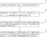
图1是本发明一种均匀圆阵相位干涉仪测向方法的流程示意图;Fig. 1 is the schematic flow chart of a kind of uniform circular array phase interferometer direction finding method of the present invention;
图2是本发明中六元均匀圆阵干涉仪示意图。2 is a schematic diagram of a six-element uniform circular array interferometer in the present invention.
具体实施方式Detailed ways
下面将结合附图对本发明的技术方案进行清楚、完整地描述,显然,所描述的实施例是本发明一部分实施例,而不是全部的实施例。基于本发明中的实施例,本领域普通技术人员在没有做出创造性劳动前提下所获得的所有其他实施例,都属于本发明保护的范围。The technical solutions of the present invention will be clearly and completely described below with reference to the accompanying drawings. Obviously, the described embodiments are a part of the embodiments of the present invention, but not all of the embodiments. Based on the embodiments of the present invention, all other embodiments obtained by those of ordinary skill in the art without creative efforts shall fall within the protection scope of the present invention.
如图1所示,本实施例公开了一种均匀圆阵相位干涉仪测向方法,包括以下步骤:As shown in FIG. 1 , this embodiment discloses a method for direction finding of a uniform circular array phase interferometer, which includes the following steps:
步骤S1:N元均匀圆阵各个天线同时接收一段长度的信号,消除射频通道相位差异;Step S1: each antenna of the N-element uniform circular array simultaneously receives a signal of a length to eliminate the phase difference of the radio frequency channel;
步骤S2:根据基线(i,i+p)与基线(i+q,i+q+p),计算相位差φi,i+p与φi+q,i+q+p,结合模糊相位组合构造多组复数{fipq};Step S2: Calculate the phase difference φi,i+p and φi+q,i+q+p according to the baseline (i,i+p) and the baseline (i+q,i+q+p), and combine the fuzzy phase Combine to construct multiple sets of complex numbers {fipq };
步骤S3:通过聚类法分析某一组复数中各元素与其他组元素聚类程度,过滤聚类程度较低或模值大于1的元素,并利用剩余元素计算所有可能的到达角;Step S3: analyze the clustering degree of each element in a certain group of complex numbers and other groups of elements by the clustering method, filter the elements with a lower clustering degree or a modulus value greater than 1, and use the remaining elements to calculate all possible angles of arrival;
步骤S4:对于各个可能的到达角,利用阵元位置、波长、圆阵半径等信息生成导向矢量并结合由各个天线接收信号组成的矢量生成信号S,计算信号能量,取能量最强的角度作为估计值。Step S4: For each possible angle of arrival, use the array element position, wavelength, circular array radius and other information to generate a steering vector, and combine the vector composed of the signals received by each antenna to generate a signal S, calculate the signal energy, and take the angle with the strongest energy as estimated value.
进一步的,所述步骤S1中包括以下步骤:Further, the step S1 includes the following steps:
步骤S11:N元均匀圆阵半径R,阵元间隔弧度ω=2π/N,依次编号1,2,...,N,阵元同时接收波长为λ由天线阵俯仰角θ、方位角

步骤S12:信号长度越长,相位差的测量精度越高,单次测量时,相位差的测量精度与信噪比存在如下关系:

步骤S13:补偿射频通道相位差异,相位差异通过天线阵远场法线方向的信号源进行标校,因为此时各天线接收信号中不存在入射角度引入的相位差异,解析的相位差异由射频通道与元器件引起。Step S13: Compensate the phase difference of the radio frequency channel, and the phase difference is calibrated by the signal source in the normal direction of the far field of the antenna array, because there is no phase difference caused by the incident angle in the received signal of each antenna at this time, and the analyzed phase difference is determined by the radio frequency channel. caused by components.
进一步的,所述步骤S2中包括以下步骤:Further, the step S2 includes the following steps:
步骤S21:基线(i,i+p)与基线(i+q,i+q+p)不平行,基线(i,i+p)由第mod(i-1,N)+1个与第mod(i+p-1,N)+1个天线阵元组成,其相位差为:Step S21: The baseline (i, i+p) is not parallel to the baseline (i+q, i+q+p), and the baseline (i, i+p) is determined by mod(i-1, N)+1 and the mod(i+p-1,N)+1 antenna array elements, the phase difference is:

步骤S22:结合波长、天线阵面尺寸、测向范围,其最大相位模糊数为

类似的,基线(i+q,i+q+p)的相位差为:Similarly, the phase difference of the baseline (i+q, i+q+p) is:

步骤S23:结合波长、天线阵面尺寸、测向范围,其最大相位模糊数为

基线(i,i+p)与基线(i+q,i+q+p)相位差之和为:The sum of the phase differences between the baseline (i, i+p) and the baseline (i+q, i+q+p) is:

基线(i,i+p)与基线(i+q,i+q+p)相位差之差为:The difference between baseline (i, i+p) and baseline (i+q, i+q+p) phase difference is:

步骤S24:定义:Step S24: Definition:


结合模糊相位差集合,构造一组复数:Combine the fuzzy phase difference set to construct a set of complex numbers:

通过i的取值变化(i=1,2,...,N),构造N组复数。By changing the value of i (i=1, 2, . . . , N), N groups of complex numbers are constructed.
进一步的,所述步骤S3中包括以下步骤:Further, the step S3 includes the following steps:
步骤S31:以某一组复数fipq为参考,该组中每个元素与其余各组的某个元素接近,即它们聚类程度最高,这几个互相接近的元素对应着真实的来波方向,计算该组中每个元素到其余各组各个元素的距离,如有元素模值大于1,则两者距离设置为极大值;Step S31: Taking a certain group of complex numbers fipq as a reference, each element in the group is close to an element in the other groups, that is, they have the highest degree of clustering, and these elements that are close to each other correspond to the real incoming wave. direction, and calculate the distance from each element in this group to each element in the other groups. If the element modulus value is greater than 1, the distance between the two is set to the maximum value;
步骤S32:搜索该组中每个元素到其余各组元素的最短距离,再将每个元素对应的N-1个最短距离求和,找出该组中距离和最小的元素类;Step S32: search the shortest distance from each element in the group to the remaining elements of each group, then sum the N-1 shortest distances corresponding to each element, and find the element class with the smallest distance and the smallest in the group;
步骤S33:该组中至少存在一个元素类,根据元素类中的元素计算出所有可能的到达角:Step S33: There is at least one element class in the group, and all possible angles of arrival are calculated according to the elements in the element class:

进一步的,所述步骤S4中包括以下步骤:Further, the step S4 includes the following steps:
步骤S41:对于每个可能的到达角
步骤S42:利用各个阵元消除射频通道相位差异后的信号组成N×L维数据矢量R;Step S42: forming an N×L-dimensional data vector R by using the signals obtained by eliminating the phase difference of the radio frequency channel from each array element;
步骤S43:计算S=AHR,得到1×L维数据矢量S,并获得其元素能量和P,即P=∑|si|2,si为数据矢量S中的第i个元素;Step S43: Calculate S=AH R, obtain a 1×L-dimensional data vector S, and obtain its element energy and P, that is, P=∑|si |2 , si is the i-th element in the data vector S;
步骤S44:每个可能的到达角度对应一个能量,能量最大对应的角度作为无模糊的到达角度估计值。Step S44 : each possible angle of arrival corresponds to an energy, and the angle corresponding to the maximum energy is used as the estimated value of the angle of arrival without ambiguity.
实施例:Example:
六元(N=6)均匀圆阵如图2所示,半径R=λ/2,阵元间隔弧度ω=π/3,依次编号1,2,...,6。定义俯仰角为信号入射方向与XOY平面夹角,定义方位角为信号入射方向在XOY平面的投影与X轴的夹角。阵元同时接收波长为λ由天线阵俯仰角θ、方位角

信号长度L=1024时,相位差的测量精度为
补偿射频通道相位差异,相位差异通过天线阵远场法线方向的信号源进行标校,因为此时各天线接收信号中不存在入射角度引入的相位差异,解析的相位差异由射频通道与元器件引起。Compensate the phase difference of the RF channel. The phase difference is calibrated by the signal source in the far-field normal direction of the antenna array, because there is no phase difference caused by the incident angle in the received signal of each antenna at this time, and the analytical phase difference is determined by the RF channel and the components. cause.
p=3,q=1;p=3, q=1;
基线(i,i+3)与基线(i+1,i+4)不平行,基线(i,i+3)由第mod(i-1,6)+1个与第mod(i+3-1,6)+1个天线阵元组成,其相位差为:The baseline (i, i+3) is not parallel to the baseline (i+1, i+4), and the baseline (i, i+3) consists of the mod(i-1,6)+1 and mod(i+3) -1,6)+1 antenna array elements, the phase difference is:

结合波长、天线阵面尺寸、测向范围,其最大相位模糊数为
类似的,基线(i+1,i+4)的相位差为:Similarly, the phase difference of the baseline (i+1, i+4) is:

结合波长、天线阵面尺寸、测向范围,其最大相位模糊数为
基线(i,i+3)与基线(i+1,i+4)相位差之和为:The sum of the phase differences between the baseline (i, i+3) and the baseline (i+1, i+4) is:

基线(i,i+3)与基线(i+1,i+4)相位差之差为:The difference between the phase difference between the baseline (i, i+3) and the baseline (i+1, i+4) is:

定义:definition:


结合模糊相位差集合,构造一组复数:Combine the fuzzy phase difference set to construct a set of complex numbers:

通过i的取值变化(i=1,2,...,6),构造6组复数。By changing the value of i (i=1,2,...,6), 6 groups of complex numbers are constructed.
以第一组复数f1pq为参考,该组中每个元素与其余各组的某个元素接近,即它们聚类程度最高,这几个互相接近的元素对应着真实的来波方向,计算该组中每个元素到其余各组各个元素的距离,如有元素模值大于1,则两者距离设置为极大值;Taking the first group of complex numbers f1pq as a reference, each element in this group is close to an element in the other groups, that is, they have the highest degree of clustering, and these elements that are close to each other correspond to the true incoming wave direction, calculate The distance between each element in this group and each element in the other groups, if the element modulus value is greater than 1, the distance between the two is set to the maximum value;
搜索该组中每个元素到其余各组元素的最短距离,再将每个元素对应的5个最短距离求和,找出该组中距离和最小的元素类;Search for the shortest distance from each element in the group to the other elements in the other groups, and then sum the 5 shortest distances corresponding to each element to find the element class with the smallest distance and the smallest distance in the group;
该组中至少存在一个元素类,根据元素类中的元素计算出所有可能的到达角:At least one element class exists in the group, and all possible angles of arrival are calculated from the elements in the element class:

对于每个可能的到达角
利用各个阵元消除射频通道相位差异后的信号组成6×1024维数据矢量R;The signal after eliminating the phase difference of the radio frequency channel by each array element forms a 6×1024-dimensional data vector R;
计算S=AHR,得到1×1024维数据矢量S,并获得其元素能量和P,即P=∑|si|2,si为数据矢量S中的第i个元素;Calculate S=AH R, obtain a 1×1024-dimensional data vector S, and obtain its element energy and P, that is, P=∑|si |2 , si is the i-th element in the data vector S;
每个可能的到达角度对应一个能量,能量最大对应的角度作为无模糊的到达角度估计值。Each possible angle of arrival corresponds to an energy, and the angle corresponding to the maximum energy is used as an unambiguous angle of arrival estimate.
以上所述,仅为本发明较佳的具体实施方式,但本发明的保护范围并不局限于此,任何熟悉本技术领域的技术人员在本发明揭露的技术范围内,可轻易想到的变化或替换,都应涵盖在本发明的保护范围之内。因此,本发明的保护范围应该以权利要求的保护范围为准。The above description is only a preferred embodiment of the present invention, but the protection scope of the present invention is not limited to this. Substitutions should be covered within the protection scope of the present invention. Therefore, the protection scope of the present invention should be subject to the protection scope of the claims.
Claims (5)


Priority Applications (1)
| Application Number | Priority Date | Filing Date | Title |
|---|---|---|---|
| CN202210556189.7ACN114966528B (en) | 2022-05-20 | 2022-05-20 | A Direction Finding Method Using Uniform Circular Array Phase Interferometer |
Applications Claiming Priority (1)
| Application Number | Priority Date | Filing Date | Title |
|---|---|---|---|
| CN202210556189.7ACN114966528B (en) | 2022-05-20 | 2022-05-20 | A Direction Finding Method Using Uniform Circular Array Phase Interferometer |
Publications (2)
| Publication Number | Publication Date |
|---|---|
| CN114966528Atrue CN114966528A (en) | 2022-08-30 |
| CN114966528B CN114966528B (en) | 2025-07-15 |
Family
ID=82985063
Family Applications (1)
| Application Number | Title | Priority Date | Filing Date |
|---|---|---|---|
| CN202210556189.7AActiveCN114966528B (en) | 2022-05-20 | 2022-05-20 | A Direction Finding Method Using Uniform Circular Array Phase Interferometer |
Country Status (1)
| Country | Link |
|---|---|
| CN (1) | CN114966528B (en) |
Citations (12)
| Publication number | Priority date | Publication date | Assignee | Title |
|---|---|---|---|---|
| US4633257A (en)* | 1983-11-14 | 1986-12-30 | Sanders Associates, Inc. | Acquisition system employing circular array |
| WO2002025574A2 (en)* | 2000-09-22 | 2002-03-28 | Http Insights Limited | Data clustering methods and applications |
| WO2004088347A1 (en)* | 2003-03-31 | 2004-10-14 | Da Tang Mobile Communications Equipment Co., Ltd. | Method for estimating the direction of arrival of fixation beam in space |
| CN102411136A (en)* | 2011-08-09 | 2012-04-11 | 电子科技大学 | Phase interferometer direction finding method for extended baseline ambiguity resolution |
| CN103731189A (en)* | 2014-01-08 | 2014-04-16 | 桂林电子科技大学 | Conformal antenna array dynamic subarray partitioning method and direction of arrival estimation method |
| US20140152504A1 (en)* | 2012-12-02 | 2014-06-05 | Khalifa University of Science, Technology & Research (KUSTAR) | Method and system for measuring direction of arrival of wireless signal using circular array displacement |
| CN104122527A (en)* | 2014-07-14 | 2014-10-29 | 中国人民解放军国防科学技术大学 | Circular array phase position interferometer broadband instantaneous direction finding method based on table lookup method |
| CN110007267A (en)* | 2019-01-29 | 2019-07-12 | 杭州电子科技大学 | A kind of uniform circular array interferometer direction finding ambiguity solution method based on mixed baseline |
| DE102018131116A1 (en)* | 2018-12-06 | 2020-06-10 | Rohde & Schwarz GmbH & Co. Kommanditgesellschaft | Bearing method for at least one high-frequency signal and bearing system |
| CN111366891A (en)* | 2020-03-23 | 2020-07-03 | 电子科技大学 | A Single Snapshot Direction Finding Method for Uniform Circular Arrays Based on Pseudo-Covariance Matrix |
| CN112198473A (en)* | 2020-08-14 | 2021-01-08 | 湖南艾科诺维科技有限公司 | Phase ambiguity resolving method based on uniform circular array direction finder and electronic equipment |
| CN114019445A (en)* | 2021-09-22 | 2022-02-08 | 中国电子科技集团公司第二十九研究所 | A two-dimensional angle of arrival measurement method based on dynamic sparse reconstruction of location clustering |
- 2022
- 2022-05-20CNCN202210556189.7Apatent/CN114966528B/enactiveActive
Patent Citations (12)
| Publication number | Priority date | Publication date | Assignee | Title |
|---|---|---|---|---|
| US4633257A (en)* | 1983-11-14 | 1986-12-30 | Sanders Associates, Inc. | Acquisition system employing circular array |
| WO2002025574A2 (en)* | 2000-09-22 | 2002-03-28 | Http Insights Limited | Data clustering methods and applications |
| WO2004088347A1 (en)* | 2003-03-31 | 2004-10-14 | Da Tang Mobile Communications Equipment Co., Ltd. | Method for estimating the direction of arrival of fixation beam in space |
| CN102411136A (en)* | 2011-08-09 | 2012-04-11 | 电子科技大学 | Phase interferometer direction finding method for extended baseline ambiguity resolution |
| US20140152504A1 (en)* | 2012-12-02 | 2014-06-05 | Khalifa University of Science, Technology & Research (KUSTAR) | Method and system for measuring direction of arrival of wireless signal using circular array displacement |
| CN103731189A (en)* | 2014-01-08 | 2014-04-16 | 桂林电子科技大学 | Conformal antenna array dynamic subarray partitioning method and direction of arrival estimation method |
| CN104122527A (en)* | 2014-07-14 | 2014-10-29 | 中国人民解放军国防科学技术大学 | Circular array phase position interferometer broadband instantaneous direction finding method based on table lookup method |
| DE102018131116A1 (en)* | 2018-12-06 | 2020-06-10 | Rohde & Schwarz GmbH & Co. Kommanditgesellschaft | Bearing method for at least one high-frequency signal and bearing system |
| CN110007267A (en)* | 2019-01-29 | 2019-07-12 | 杭州电子科技大学 | A kind of uniform circular array interferometer direction finding ambiguity solution method based on mixed baseline |
| CN111366891A (en)* | 2020-03-23 | 2020-07-03 | 电子科技大学 | A Single Snapshot Direction Finding Method for Uniform Circular Arrays Based on Pseudo-Covariance Matrix |
| CN112198473A (en)* | 2020-08-14 | 2021-01-08 | 湖南艾科诺维科技有限公司 | Phase ambiguity resolving method based on uniform circular array direction finder and electronic equipment |
| CN114019445A (en)* | 2021-09-22 | 2022-02-08 | 中国电子科技集团公司第二十九研究所 | A two-dimensional angle of arrival measurement method based on dynamic sparse reconstruction of location clustering |
Non-Patent Citations (1)
| Title |
|---|
| 王琦: "圆阵干涉仪测向研究", 航天电子对抗, vol. 25, no. 5, 31 October 2009 (2009-10-31), pages 33 - 35* |
Also Published As
| Publication number | Publication date |
|---|---|
| CN114966528B (en) | 2025-07-15 |
Similar Documents
| Publication | Publication Date | Title |
|---|---|---|
| AU2022259835B2 (en) | Direction of arrival estimation | |
| CN108344967A (en) | 2-d direction finding method for quick estimating based on relatively prime face battle array | |
| US6377214B1 (en) | Pipelined processing algorithm for interferometer angle of arrival estimation | |
| CN114460531A (en) | Uniform linear array MUSIC spatial spectrum estimation method | |
| CN117706467A (en) | Interferometer array method | |
| CN111190135A (en) | Calibration method suitable for any array | |
| CN114487992B (en) | Multi-baseline phase interferometer direction finding method without ambiguity resolution | |
| CN113721184A (en) | Near-field signal source positioning method based on improved MUSIC algorithm | |
| CN106569180B (en) | Prony method-based orientation estimation algorithm | |
| CN114236462B (en) | A high-precision spatial spectrum direction finding method based on a specific non-equidistant array structure | |
| CN116087871A (en) | Direction finding method, device and system for circular array interferometer and storage medium | |
| CN113504554B (en) | Direction finding method of non-uniform subarray synthetic interferometer based on spaceborne phased array | |
| CN112198473B (en) | Phase disambiguation method based on uniform circular array direction finder and electronic equipment | |
| CN114966528B (en) | A Direction Finding Method Using Uniform Circular Array Phase Interferometer | |
| CN119165442A (en) | A single-satellite direct positioning method based on space-time signal model and related equipment | |
| CN113702898A (en) | Known waveform source direction-of-arrival estimation method based on distributed array | |
| Zhou et al. | An Efficient Phase Interferometer Direction-Finding Algorithm Based on Circular Array | |
| CN114200391B (en) | A Direction of Arrival Estimation and Positioning Method for Arbitrary Planar Sensor Arrays | |
| CN112946615B (en) | A Correction Method of Amplitude and Phase Error in Phased Array System | |
| CN116500543A (en) | Incoming wave angle rapid estimation method based on reference direction transformation | |
| CN113050029B (en) | Phase interferometer direction finding method suitable for array element failure condition | |
| CN111474534B (en) | Two-dimensional DOA estimation method based on symmetric parallel nested array | |
| CN114518557B (en) | A Direction Finding Method Based on Projection Coincidence | |
| CN119270189B (en) | Phase calibration method and device for small interferometer system | |
| CN119126010A (en) | A three-dimensional interferometer deambiguation direction finding method |
Legal Events
| Date | Code | Title | Description |
|---|---|---|---|
| PB01 | Publication | ||
| PB01 | Publication | ||
| SE01 | Entry into force of request for substantive examination | ||
| SE01 | Entry into force of request for substantive examination | ||
| GR01 | Patent grant | ||
| GR01 | Patent grant |